


Yamato AZ7000SDR-8, AZ7003SDR-8, AZ7016SDR-8, AZ7020SDR-8, AZ7025SDR-8 Manual
...Instruction Manual
SUPPER HIGH SPEED OVERLOCK MACHINE SUPPER HIGH SPEED SAFETY STITCH MACHINE
AZ7000SDR-8 class
AZ7000SDR-8,AZ7003SDR-8,AZ7016SDR-8 AZ7020SDR-8,AZ7025SDR-8,AZ7120SDR-8,AZ7125SDR-8
AZ7500SDR-8 class
AZ7500SDR-8,AZ7520SDR-8,AZ7525SDR-8 AZ7500SDR-31,AZ7520SDR-31,AZR7525SDR-31
Thank you for purchasing the AZ7000SDR-8 and AZ7500SDR-8 class. Before using your AZ7000SDR-8 and AZ7500SDR-8 class, please read the instruction manual and understand the contents well.
After reading the instruction manual, please keep it in a location where it is easily accessible to the operator.

CONTENTS
SAFETY INSTRUCTIONS
1. Name of each part |
1 |
||
|
|
|
|
2. Installation |
2 |
||
|
|
|
|
2.1 |
Semi-submerged type |
2 |
|
|
|
|
|
2.1.1 |
Table cutting diagram |
2 |
|
|
|
|
|
2.1.2 |
Installation |
3 |
|
|
|
|
|
2.2 |
Fully-submerged type |
4 |
|
|
|
|
|
2.2.1 |
Table cutting diagram |
4 |
|
|
|
|
|
2.2.2 |
Table cutting diagram for fully-submerged type with device |
6 |
|
|
|
|
|
2.2.3 |
Installation |
7 |
|
|
|
|
|
2.3 |
Motor, pulley and belt |
8 |
|
|
|
|
|
2.4 |
Hanging belt |
9 |
|
|
|
|
|
2.5 |
Belt cover |
9 |
|
|
|
|
|
2.6 |
Eye guard and finger guard |
9 |
|
|
|
|
|
3. |
Sewing speed and rotating direction of pulley |
10 |
|
|
|
|
|
4. |
Lubrication |
11 |
|
|
|
|
|
|
4.1 |
Lubricating oil |
11 |
|
|
|
|
|
4.2 |
Lubricating |
11 |
|
|
|
|
|
4.3 |
Changing oil |
12 |
|
|
|
|
|
4.4 |
Checking and replacing oil filter |
12 |
|
|
|
|
5. Proper operation |
13 |
|
|
|
|
5.1 |
Needle system |
13 |
|
|
|
5.2 |
Installing needles |
13 |
|
|
|
5.3 |
Adjusting thread tension |
14 |
|
|
|
5.4 |
Pressure of presser foot |
15 |
|
|
|
5.5 |
Releasing presser foot |
15 |
|
|
|
5.6 |
Opening cover |
16 |
|
|
|
5.7 |
Adjusting differential feed dog |
16 |
|
|
|
5.8 |
Adjusting stitch length |
17 |
|
|
|
5.9 |
Passing tape |
18 |
|
|
|
5.10 |
SP device and HR device |
18 |
|
|
|
5.11 |
Cleaning the machine |
19 |
|
|
|
6. Adjustment of sewing machine |
20 |
|
|
|
|
6.1 |
Needle thread tension for overlock stitch |
20 |
|
|
|
6.2 |
Looper thread tension for overlock stitch |
21 |
|
|
|
6.3 |
Needle thread tension for double chainstitch |
22 |
|
|
|
6.4 |
Looper thread tension for double chainstitch |
23 |
|
|
|

CONTENTS
6.5 |
Width of overedge seam |
24 |
|
|
|
6.6 |
Upper and lower knives |
25 |
|
|
|
6.7 |
Height of feed dogs |
27 |
|
|
|
6.8 |
Tilt of feed dog |
28 |
|
|
|
6.9 |
Needles and loopers |
29 |
|
|
|
6.9.1 |
Height of needle |
29 |
|
|
|
6.9.2 |
Installing angle of lower looper |
30 |
|
|
|
6.9.3 |
Distance between needle and lower looper |
30 |
|
|
|
6.9.4 |
Parallel of needles |
31 |
|
|
|
6.9.5 |
Back and forth position of lower looper |
32 |
|
|
|
6.9.6 |
Distance between needle and upper looper |
33 |
|
|
|
6.9.7 |
Back and forth position of upper looper |
34 |
|
|
|
6.9.8 |
Timing relation between lower looper and upper looper |
34 |
|
|
|
6.10 |
Needle and double chaining looper |
34 |
|
|
|
6.11 |
Needle and needle guards for AZ7000SDR-8 |
35 |
|
|
|
6.11.1 |
Needle and needle guard(rear) |
35 |
|
|
|
6.11.2 |
Needle and needle guard(front) |
35 |
|
|
|
6.12 |
Needle and needle guards for AZ7500SDR-8 |
36 |
|
|
|
6.12.1 |
Needle and needle guard(rear) |
36 |
|
|
|
6.12.2 |
Needle and needle guard(front) |
36 |
|
|
|
6.12.3 |
Needle and needle guard for double chain stitch |
37 |
|
|
|
6.13 |
Position of presser foot |
37 |
|
|
|
7. SC10 device |
38 |
||
|
|
|
|
7.1 |
Outline |
38 |
|
|
|
|
|
7.2 |
Adjusting ventilating amount |
38 |
|
|
|
|
|
7.3 |
Installation |
39 |
|
|
|
|
|
8. K2 device |
41 |
||
8.1Adjustment for engagement between upper trimming knife and lower trimming knife 41
8.2 Oiling 41
9. Specifications |
|
42 |
|
|
|
|
|
9.1 |
AZ7000SDR-8 |
class |
42 |
|
|
|
|
9.2 |
AZ7500SDR-8 |
class |
43 |
|
|
|
|
Attention
This instruction manual is designed mainly for technicians, but it is advisable that also operators read the instructions with mark to use the machine properly.
The numbers in lower left corners of figures are figure numbers. We use them in texts as needed for your reference.
Attention
The parts used for this product |
are subject to change without notice. If such a change is made, any part |
of the contents and illustrations |
of this instruction manual may not conform to this product. |
In preparing the instruction manual, we have made our best efforts for making it free of any error or omission. If any error or omission should yet be found, it might not be rectified immediately.
 SAFETY INSTRUCTIONS
1. Safety Instruction
The sewing machine, automatic machine, and attachments (collectively called“the machine”below) involve sewing operations that require the operator to be near moving parts of the machine. Because of this, there is always a potential danger of unintentional contact with the moving parts. For this reason, the operators who actually use the machine and the maintenance staff who perform maintenance and repair must carefully read“2. Basic precautions”and“3. Precautions to be taken in various operating stage”below and fully understand this information before operating or maintaining the machine.
The information contained in the“Safety Instruction”of this manual also includes items not found in the product specifications.
To assist in better understanding this manual and the product warning labels, warning indicators are categorized as shown below. Be sure that you fully understand the contents and carefully follow the instructions.
1.1 Explanation of risk levels
|
This indication is given when there is a danger of death or serious injury if |
DANGER |
the person in charge or any third party mishandles the machine or does not |
|
avoid the dangerous situation when operating or maintaining the machine. |
|
This indication is given when there is a potential for death or serious injury |
WARNING |
if the person in charge or any third party mishandles the machine or does not |
|
avoid the dangerous situation when operating or maintaining the machine. |
|
This indication is given when there is a potential danger of medium to minor |
CAUTION |
injury or damage of the sewing machine if the person in charge or any third |
party mishandles the machine or does not avoid the dangerous situation when |
|
|
operating or maintaining the machine. |
1.2 Explanation of pictorial warning indications and warning labels
There is a risk of injury if contacting a moving section.
There is a risk of a burn if contacting a high-temperature section.
There is a risk of electrical shock if contacting a high-voltage section.
Connection of an earth cable is indicated.
The correct direction is indicated.
Explanation of safety label
There is the possibility that slight to serious injury or death may be caused.
There is the possibility that injury may be caused by
|
|
|
touching the moving |
part. |
|
|
|
Perform sewing work with safety cover. |
|
|
|
|
Perform sewing work with safety protection device. |
|
|
|
|
Be sure to turn the power OFF before carrying out |
|
|
|
|
“threading,”“needle changing,”“bobbin changing”or |
|
|
|
|
“oiling and cleaning.” |
|
Explanation of high-voltage warning label
High voltages are flowing inside the power supply of the control box. This indicates that there is a risk of electrical shock. When it is necessary to open the control box containing electrical parts, be sure to turn the power off, remove the power plug and wait for at least five minutes before opening the cover in order to prevent an accident resulting in electrical shock.
i

 SAFETY INSTRUCTINONS
1.3 Explanation of symbols
Explains the symbols used in the instruction manual.
Failure to follow the instructions can result in an injury or damage to the machine.
Be sure to follow the instructions when you operate, check, adjust or repair the machine.
Never do this.
Be sure to remove the power plug from the source of the power supply, when checking, adjusting and/or repairing the machine or when there is the possibility that lightning may strike.
Additional explanations and notes, etc., for operation or adjustment
2. Basic precautions
1.Be sure to read this instruction manual and all the other explanatory documents supplied with accessories of the machine before using the machine. Always keep the instruction manual where it is easily accessible for the operator and maintenance staff.
2.The content of this section includes items which are not contained in the specifications of your product.
3.Be sure to wear safety goggles to protect against accidents caused by needle breakage.
2.1 Applications, purpose
Our industrial sewing machines have been developed in order to increase quality and/or productivity in the sewing industry. Accordingly, never use our products for other than the intended use as described above.
2.2 Working environment
The environment in which our industrial sewing machines are used may seriously affect their durability, functions, performance and/or safety. Do not use the machine in the circumstances below.
 Places of high ambient temperature and/or humidity that seriously affects sewing machines.
 Outdoors, places of high temperature or in direct sunlight.
 Environments containing dust, corrosive or flammable gases, or in contact with chemicals.
 Where the voltage fluctuation range is more than ± 10% of the rated voltage.
 Location where sufficient power is not available for the power supply capacity of the controllers and motors that is used.
 Near objects where strong electric or magnetic fields, such as high frequency welding machines which make noise, are generated.
 As dew condensation may occur when suddenly bringing the machine from a cold environment to a warm place, in order to prevent accidents caused by breakage or malfunction of the
electrical components, be sure to turn the power on after waiting for a sufficient period of time until there is no sign of water droplets.
 When lightning occurs, be sure to stop operation and remove the power plug in order to prevent accidents caused by breakage or malfunction of the electrical components.
2.3 Safety devices and warning labels
 Be sure to operate the machine after verifying that safety device(s) are correctly installed
in order to prevent accidents caused by lack of the device(s).
With regard to safety device(s), please refer to page vi.
 If any of the safety devices is removed, be sure to replace it and verify that it works
normally in order to prevent accidents.
 Be sure to keep the safety label and/ or warning lables attached to the machine
clearly visible in order to prevent accidents. If any of the labels has become stained or come unstuck, be sure to replace it with a new one.
2.4 Instruction and training
○Operators and workers, who supervise, repair or maintain the machine head and/or machine unit, are required to have the adequate knowledge and operation skills to do the job safely.
○The manager should plan and enforce the safety education and training of those operators and workers beforehand.
2.5 Modification
 Never modify and/or alter the machine in order to prevent accident that can result in
personal injury or death. Yamato assumes no responsibility for damages or personal injury or death resulting from a machine which has been modified or altered.
ii

 SAFETY INSTRUCTINONS
 WARNING
2.6Items for which the power to the machine has to be turned off
Be sure to immediately turn the power off if any abnormality or failure is found or in the case of power failure in order to protect against accidents that can result in personal injury or death.
To protect against accidents resulting from abrupt starting of the machine, be sure to carry out the following operations after turning the power off.
●When threading to the parts such as the needle, looper, spreader, etc., or when changing the bobbin.
●When changing or adjusting all component parts of the machine.
●Adjusting the stitch length
●Adjusting the differential feed ratio
●When inspecting, repairing or cleaning the machine or leaving the machine.
○Be sure to remove the power plug by holding the plug section instead of the cord section in order to prevent electrical shock, earth- leakage or fire accidents.
○If the machine is using a clutch motor, to protect against accidents resulting from abrupt starting of the machine, be sure to carry out the above operations after verifying that the machine has stopped completely, since the motor continues turning for a while even after turning off the power supply switch.
3 PRECAUTIONS TO BE TAKEN IN VARIOUS OPERATING STAGES
3.1 Unpacking
 Be sure to unpack the machine from the top. If the machine is packed in a wooden crate, be careful of the nails. Remove the nails from the board.
 Never hold the parts near the needle or threading parts when removing the sewing machine head from the buffer of the box.
 Removing and carrying the sewing machine head should always be carried out by two or more people.
 Take out the machine very carefully while checking the position of the center of gravity.
 Preserve the cardboard box and packing material carefully in case secondary transport is needed in the future.
Disposal of the packaging
The packaging material of the machine consists of wood, paper, cardboard and polystyrene foam. The proper disposal of the packaging is the responsibility of the customer, and must be
properly disposed of in accordance with the locally valid environmental protection regulations.
Disposal of the machine waste
The proper disposal of the machine waste is the responsibility of the customer, and must be disposed of in accordance with the locally valid environmental protection regulations.
The materials used in the machines are steel, aluminum, brass and various plastics.
A specialist should be commissioned if necessary.
3.2 Transportation
 Be sure to take sufficient safety measures to prevent falling or dropping when lifting or
moving the machine.
 If the machine and/or your hands are stained with oil, the machine may easily fall to the
floor. Therefore, wipe off the oil carefully.
 To prevent accidents during transportation, repackage in the same state as the original
delivery packaging.
Be particularly sure to fully wipe off any oil adhering to the machine before repackaging.
 The machine head should be carried by two or more people.
The machine should be carried by people only when moving to the table or transfer hand truck, and all other transportation operations should use a hand truck. When moving to the table or hand truck, be careful that the machine is not subjected to
excessive impact or vibrations. Otherwise the sewing head could fall over.
 When handling the machine, do not carry the bottom part of the cloth plate cover.
iii

 SAFETY INSTRUCTINONS
3.3 Installation, preparation
3.3.1 Machine table
 Prepare a machine table (table board and legs) that has sufficient strength to withstand the weight of the sewing head and any reaction while operating.
Securely join the table and legs to ensure sufficient strength to withstand the weight of the sewing head and any reaction while operating.
○Maintain a comfortable working environment with consideration of the lighting and the arrangement of sewing machine to enable the operators to work smoothly.
○Adjust the height of the table according to the posture of the worker.
Also, when installing the control box and the related parts on the sewing machine, make sure not to affect the posture of the worker.
If casters are fitted to the table stand, be sure to use high-strength casters with a locking mechanism.
 Lock the casters except when moving the machine.
3.3.2 Wiring and grounding
 Never connect the plug for power supply until assembly is finished.
Also, be sure to avoid the usage of multipleoutlet extension cords in order to prevent electrical shock, earth-leakage or fire accident.
 Fix the connectors securely to the sewing machine head, motor, and electric apparatus. Also, when unplugging the connectors, hold the connector part.
 When wiring the connection cords, please take care of the following.
○Connect the cords away from the driving parts.
○Do not apply excessive force to the connection cords.
○Do not bend the cords excessively.
 Never use staples to fasten the cables. Otherwise it may cause a short circuit and/or fire.
 Arrange the ground wire securely to the designated position on the machine head.
Also, wire separately from the grounding for other equipment.
3.3.3 Handling machine oil
 Keep machine oil out of the reach of children.
 Be sure to fill or add lubrication oil to sewing machines before operating them.
Use“Yamato SF oil 28”as specified.
 If machine oil gets in your eyes, it may cause eye inflammation. Always wear protective glasses to prevent the oil from getting in your eyes.
*Should machine oil get in your eyes, wash them with fresh water for 15 minutes and then consult a medical doctor.
 If oil adheres to your eyes or body, be sure to immediately wash it off in order to prevent inflammation or irritation.
 If oil is swallowed unintentionally, be sure to consult a medical doctor in order to prevent diarrhea or vomiting.
 Methods of disposing of waste oil and/or containers are specified by law. Dispose of it properly as required by law. If you have further questions on its disposal, consult the place of purchase.
 After opening the oil container, be sure to seal it to prevent dust and water from
getting into the oil and keep it in the dark to avoid direct sunlight.
 Do not store in high-temperature areas or areas exposed to an open flame.
 WARNING
3.4 Before operation
○Never put your hand under the needle or near the moving parts of the machine when turning on the power supply switch.
○When operating a new sewing machine, make sure the rotating direction of the pulley agrees with the rotating-direction mark.
○Before turning the power on, visually check the cables and connectors for conditions such as damage, disconnection and/or loosening.
○If a table stand with casters is used, be sure to secure the table stand by locking the casters or securing the legs with adjusters, if provided, in order to prevent accidents caused by abrupt moving of the machine.
iv

 SAFETY INSTRUCTINONS
|
WARNING |
○ |
Do not attempt to modify the machine at your |
|
3.5 During operation |
|
own discretion. We are not responsible for |
||
|
accidents caused by such modification. |
|||
|
|
|
||
○ |
Be sure to operate the sewing machine using |
○ |
Use genuine Yamato parts when repairing the |
|
|
the safeguards such as belt cover, finger |
|
machine and/or replacing the parts. We are |
|
|
guard, and eye guard. |
|
||
|
|
not responsible for accidents caused by any |
||
○ |
Never place your finger, hair or objects under |
|
||
|
improper repair/adjustment and substituting |
|||
|
the needle or close to the moving parts while |
|
||
|
|
other parts for those manufactured by Yamato. |
||
|
operating the sewing machine. |
|
||
|
○ |
Turn off the power supply switch if removing |
||
○ |
Be sure to turn off the power supply switch |
|||
|
|
|||
|
when threading or replacing the needles. |
|
or replacing any parts or during adjustment |
|
○ |
Never place your hands close to the knives |
|
of the sewing machine. |
|
|
(upper and lower knives) when operating the |
○ |
Be sure to also remove the gasket if the |
|
|
sewing machine with the trimming devices. |
|
cover is removed for maintenance, inspection, |
|
○ |
Be sure to turn off the power supply switch |
|
||
|
and repair. If the gasket is not removed, the |
|||
|
when terminating the sewing work or leaving |
|
||
|
|
edge of gasket may cause injury. |
||
|
the sewing machine. |
|
||
|
○ |
Do not pull the cord when removing the plug. |
||
○ |
In the event of the power failure, be sure to |
|||
|
turn off the power. |
|
Be sure to hold the plug itself. |
|
|
|
|
||
|
Also, if the sewing machine malfunctions, |
○ |
A high voltage is applied inside the control |
|
|
makes abnormal sound or emits unusual odors |
|
box. Turn off the power supply switch and |
|
|
while operating, be sure to turn off the |
|
wait for at least five minutes before opening |
|
|
power supply switch. |
|
the cover. |
|
○ |
While operating the machine, wear clothing |
○ |
Be sure to replace the safety devices and/ |
|
|
that cannot be caught in the machine. |
|||
|
|
or safety covers if removed for maintenance, |
||
○ |
Do not put any tools or other unnecessary |
|
||
|
inspection and repair. |
|||
|
objects on the machine table while running |
|
||
|
○ |
After performing maintenance, inspection and |
||
|
the machine. |
|||
|
|
repair, make sure that turning on the power |
||
○ |
If a clutch motor type is used, it will |
|
||
|
|
|||
|
continue running for a while even after the |
|
does not pose any danger to you. |
|
|
power is turned off. Therefore, be careful |
|
When operating the machine for the first time |
|
|
because the machine could start running by |
|
after work is performed, run at low speed to |
|
|
pressing the machine pedal. |
|
check for abnormal sounds or other problems |
|
○ |
If a servomotor is used, the motor does not |
|
||
|
before performing high-speed operation. |
|||
|
produce noise while the machine is at rest. |
|
||
|
|
|
||
|
Be sure not to forget to turn the power off |
|
|
|
|
in order to prevent accidents caused by |
|
|
|
|
abrupt starting of the machine or motor. |
4.Recommended check points for maintaining |
||
○ |
To prevent entanglement accidents in machines |
machine performance |
||
|
with a puller mechanism, keep your hands, |
|||
|
|
|
||
hair, and clothing away from the machine. |
(1) Perform regular cleaning of the machine parts |
|
|
|
by following the instruction manual. |
|
(2) Perform regular inspection of the lubrication |
|
oil by following the instruction manual, and |
 WARNING
3.6 Maintenance, inspection and repair
○Maintenance, inspection, and repair must be performed by staff that have received special training and fully understand and follow the information in the instruction manual.
○Be sure to turn off the power supply switch and make sure the sewing machine and motor completely stop before the maintenance, inspection, and repair. (If the machine is using a clutch motor, take care that the motor keeps turning for a while even after turning off the power supply switch.)
refill or replace the oil as required.
(3)Because the oil-proof parts use rubber, their oil-proof performance is reduced over time.
○If the seals or other stationary parts fall off or begin to lose their sealing performance, replace them with new parts.
○The replacement period for parts used in the movable sections varies depending on the machine operating conditions, environment, maintenance, and oil used, but replacement every several years is recommended.
(4)For details about the replacement procedure, please contact your local dealer or Yamato.
v
 SAFETY INSTRUCTINONS
5. Safety devices and warning label affixing locations
Belt cover
 The belt cover prevents entanglement with the belt.
 Do not operate with the cover removed.
Front cover
 The front cover prevents contact with the moving parts inside the cover.
 Do not operate with the cover opened.
Eye guard
 The eye guard prevents injury to the operator’ s eyes due to breaking of needles during the sewing operation. This section also houses
the needle thread take-up, upper knife, and other moving parts.
 Do not operate with the eye guard opened.
Finger guard
 The finger guard prevents the operator’s fingers from going under the needle. However, there
is some space at the top of the finger guard and other sections, and so there is a risk of finger insertion.
 Do not operate when the finger guard is removed.
Cloth plate
 The cloth plate prevents contact with the moving parts inside the cloth plate.
 Do not operate when the cloth plate is opened.
Safety label, warning label
 Reaffix the labels if they start peeling off or become dirty and illegible.
Belt cover
Eye guard
 Finger guard
Safety label
Cloth plate
Front cover
vi
DECLARATION OF INCORPORATION OF PARTLY COMPLETED MACHINERY
We hereby declare that the sewing machine(sewing head) described below;
1.Must not be put into service until the machinery to which it is incorporated has been declared inconformity with the provisions of the Directive 2006/42/EC, and
2.Conforms to essential requirements of the Directive 2006/42/EC, described in the technical documentation, and
3.To be prepared with the above technical documentation compiled in accordance with part B of Annex VII, and
4.Relevant information on wish should be transmitted in response to a reasoned request by the national authorities by the electronic method or other according to the request.
Model : AZ7000SDR-8 and AZ7500SDR-8 class
Serial No. :
Description : Industrial sewing machine
Function : Make stitches and sew
Applied harmonized standards in particular :
EN ISO12100-1, EN ISO 12100-2, EN ISO10821, EN 60204-31
Manufacturer :
YAMATO SEWING MACHINE MFG. CO., LTD.
2-10-3 Hotarugaike Minami-machi Toyonaka
Osaka Japan
1.Name of each part
Oil cap
Thread tension spring cap
Presser foot release lever
SP device (behind Eyeguard)
Cloth plate
 Eye guard
Front cover
Finger guard
Oil reservoir
Drain hole screw
Presser foot
Fig. 1-1
AZ7000SDR-8, 7500SDR-8
1
2.Installation
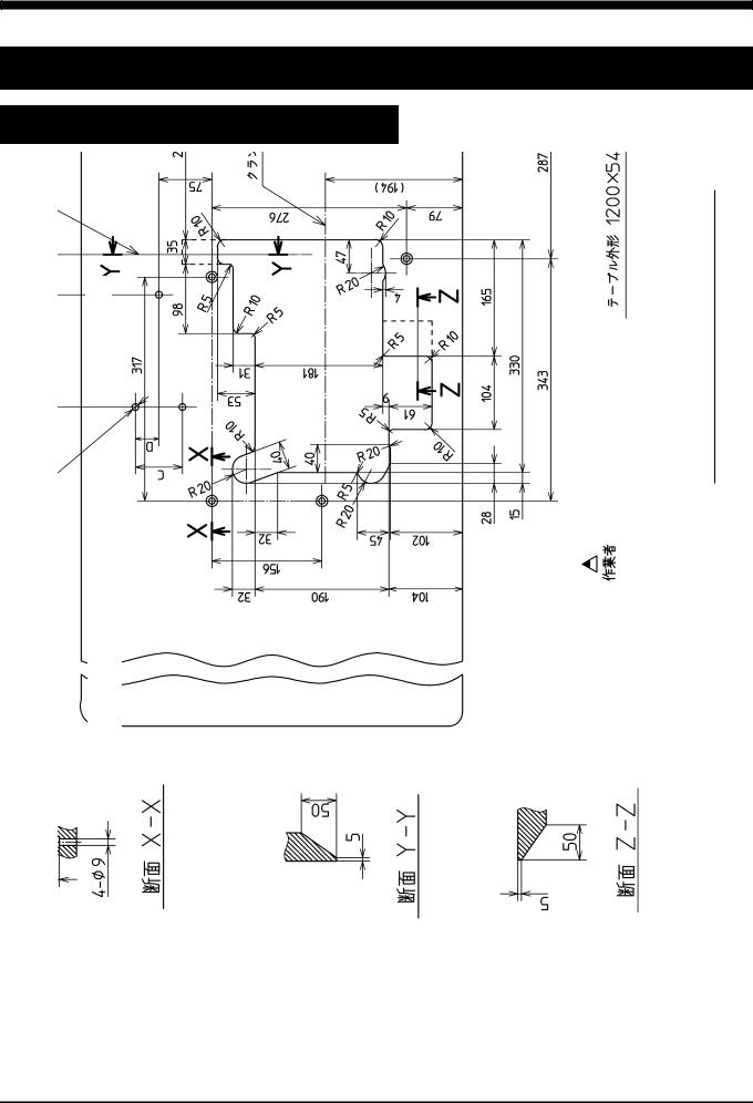
2.1 Semi-submerged type
2.1.1 Table cutting diagram
|
|
|
|
|
<![if ! IE]> <![endif]>1200×540×40 mm |
||
| <![if ! IE]> <![endif]>Centerof machinepulley |
|
<![if ! IE]> <![endif]>Center of |
<![if ! IE]> <![endif]>crank shaft |
||||
|
|
||||||
|
|
|
|||||
|
|
|
|||||
|
|
|
|
|
|
<![if ! IE]> <![endif]>dimensions |
|
|
|
|
|
|
|
||
|
|
|
|
|
|
<![if ! IE]> <![endif]>Table |
|
|
|
|
|
|
|
|
|
|
<![if ! IE]> <![endif]>3-Φ9.5 installing hole for motor |
|
|
|
<![if ! IE]> <![endif]>to the instruction man- |
<![if ! IE]> <![endif]>the motor for dimen- |
|
<![if ! IE]> <![endif]>operator |
|
||
|
|
|
|
|
|
||||||
| <![if ! IE]> <![endif]>A, B, C, and D. |
|
|
|
|
|||||||
|
|
|
|
|
|
|
|||||
|
|
|
|
|
<![if ! IE]> <![endif]>Refer |
<![if ! IE]> <![endif]>ual of |
<![if ! IE]> <![endif]>sions |
|
|
|
|
|
|
|
|
|
|
|
|
|
|
|
|
|
|
|
<![if ! IE]> <![endif]>Section X - X |
|
|
|
|
|
|
|
|
|
|
|
<![if ! IE]> <![endif]>Section Y - Y |
|
|
|
|
<![if ! IE]> <![endif]>Z |
|||
|
|
|
|
|
|
|
|
<![if ! IE]> <![endif]>Section Z - |
|||
|
|
|
|
|
|
|
|
|
|
|
|
|
|
|
|
|
|
|
|
|
|
|
|
Fig. 2-1
AZ7000SDR-8, 7500SDR-8
2
2. Installation
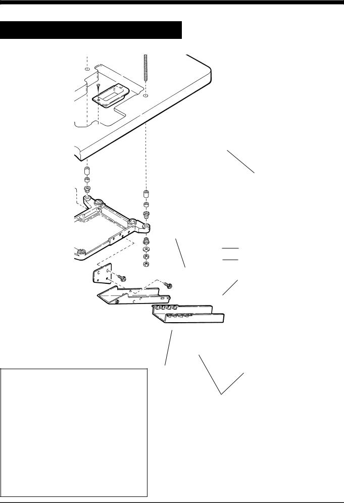
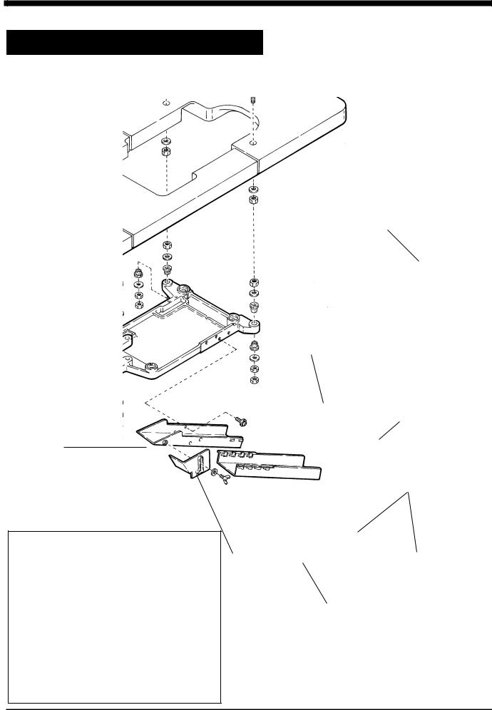
2.1.2 Installation
Install the machine correctly referring to Fig. 2-2 and 2-3.
machine table
supporting
board
 supporting board rubber cushion
Fig. 2-2
chute (upper) support
chute
Table 1 The number of spacers and
thickness of |
pcs. of |
pcs. of |
|
table |
|||
|
|
||
40 |
4 |
4 |
|
|
|
|
|
45 |
4 |
not necessary |
|
|
|
|
Size of spacers : =15 =5
Fig. 2-3
AZ7000SDR-8, 7500SDR-8
3

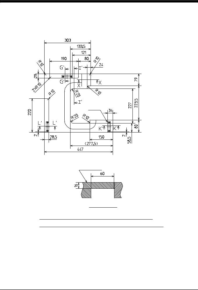
<![endif]>8-7500SDR 8,-AZ7000SDR
<![if ! IE]><![endif]>4
<![endif]>4-2 .Fig
Section E - E
auxiliary table
Section G - G G’- G’
(installing hole for motor)
magnet |
0.5(clearance) |
|
|
| <![if ! IE]> <![endif]>0.5 (clearance) |
|
|
magnet |
0.5(clearance) |
0.5(clearance) |
center of machine pulley
center of main shaft
Section I - I |
Section J - J |
I’- I’ |
|
auxiliary |
auxiliary |
table |
table |
Section L - L |
Section K - K |
L’- L’ |
K’- K’ |
|
auxiliary table
drilling
operator
Refer to the instruction manual of the motor for dimensions A, B, C, and D.
Table dimensions 1200×540×40 mm
Section H-H
Note) Indication of magnet and magnet catch plate can be referred to installation position of magnetic catch.
Ref.) Magnetic catch JM-63G-15 and magnetic catch plate AS-68 made by SUGATSUNE KOGYO Co. Ltd.
| <![if ! IE]> <![endif]>1.2.2 |
|
<![if ! IE]> <![endif]>2.2 |
| <![if ! IE]> <![endif]>diagram cutting Table |
|
<![if ! IE]> <![endif]>submerged-Fully |
|
|
<![if ! IE]> <![endif]>type |
|
|
|
|
|
|
<![endif]>Installation .2
2. Installation
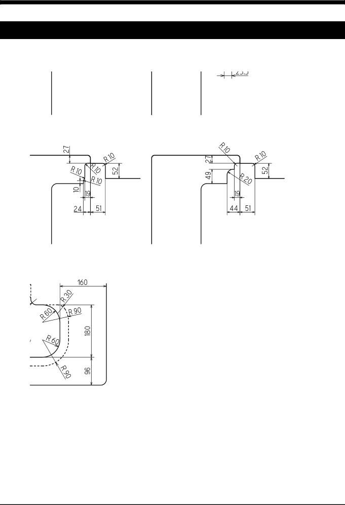
Cutting diagram of auxiliary table
3×magnet |
catch |
auxiliary table
Section X - X
Note) Indication of magnet and magnet catch plate can be referred to
installation position of magnetic catch.
Ref. ) )Magnetic catch JM-63G-15 and( magnetic) JM-63Gcatch-15plate AS-68ASmade-68 by
SUGATSUNE KOGYO Co. Ltd.
Fig. 2-5
5 |
AZ7000SDR-8, 7500SDR-8 |
2.Installation
2.2.2Table cutting diagram for fully-submerged type with device
To set up a machine with device, install the device with below dimensions and refer to “2.2.1 Table cutting diagram” (Fig. 2-4, 2-5).
AZ7500SDR-8 class with K1 device |
AZ7000SDR-8 class with K2 device |
AZ7000SDR-8, AZ7500SDR-8 classes |
AZ7000SDR-8, AZ7500SDR-8 classes |
with MT22 device |
with MU44, 45 device |
Using servomotor
Fig. 2-6
AZ7000SDR-8, 7500SDR-8 |
6 |
|
2. Installation
2.2.3 Installation
Install the machine correctly by referring to Fig. 2-7 and 2-8.
Adjust the position of supporting chine can be set horizontally set on the same height or
table.
machine table
supporting board
 supporting board rubber cushion
supporting board connector
chute
Fig. 2-7
supporting board connector
supplementary
chute cover
rubber cushion
Fig. 2-8
7 |
AZ7000SDR-8, 7500SDR-8 |
 Loading...