

Page 1
Page 2
●
Precautions
Do not expose the plug-in board to direct sunlight,
excessive humidity, high temperatures, excessive dust
or strong vibrations.
●
Before handling the plug-in board, be sure to touch a
metal surface to discharge any static electricity which
may be in your body.
●
When holding the plug-in board, do not touch the inside
area of the circuit board or apply excessive pressure to
the board, and be sure to protect the board from contact
with water or other liquids.
●
Before installing the plug-in board onto a tone generator/sound card, unplug the power connector of your
computer.
* The company names and product names in this Owner’s Manual are the trademarks or re gistered
trademarks of their respective companies.
* The screens as illustrated in this owner’s manual are for instructional purposes only, and may
appear somewhat different from the ones of your instrument.
●
Before connecting the computer to other devices, turn
off the power switches of all devices.
●
Yamaha is not responsible for loss of data through computer malfunctions or operator actions.
●
The plug-in board contains no user-serviceable parts, so
never touch the inside area of the circuit board or
tamper with the electronic circuitry in any way. Doing
so may result in electrical shock or damage to the plugin board.
YAMAHA CANNOT BE HELD RESPONSIBLE
FOR DAMAGE CAUSED BY IMPROPER
CARE AND USE OF THE PLUG-IN BOARD.
FCC INFORMATION (U.S.A.)
1. IMPORTANT NOTICE: DO NOT MODIFY THIS UNIT!
This product, when installed as indicated in the instructions contained in this manual, meets FCC requirements. Modifications
not expressly approved by Yamaha may void your authority, granted by the FCC, to use the product.
2. IMPORTANT:
Cable/s supplied with this product MUST be used. Follow all installation instructions. Failure to follow instructions could void
your FCC authorization to use this product in the USA.
3. NOTE:
”B” digital devices. Compliance with these requirements provides a reasonable level of assurance that your use of this product
in a residential environment will not result in harmful interference with other electronic devices. This equipment generates/uses
radio frequencies and, if not installed and used according to the instructions found in the users manual, may cause interference
harmful to the operation of other electronic devices. Compliance with FCC regulations does not guarantee that interference will
not occur in all installations. If this product is found to be the source of interference , which can be determined by turning the unit
”OFF” and ”ON”, please try to eliminate the problem by using one of the following measures:
Relocate either this product or the device that is being affected by the interference.
Utilize power outlets that are on different branch (circuit breaker or fuse) circuits or install AC line filter/s.
In the case of radio or TV interference, relocate/reorient the antenna. If the antenna lead-in is 300 ohm ribbon lead, change the
lead-in to co-axial type cable.
If these corrective measures do not produce satisfactory results, please contact the local retailer authorized to distribute this
type of product. If you can not locate the appropriate, please contact Yamaha Corporation of America, Electronic Service Division, 6600 Orangethorpe Ave, Buena Park, CA 90620
* This applies only to products distributed by YAMAHA CORPORATION OF AMERICA.
When connecting this product to accessories and/or another product use only high quality shielded cables.
This product has been tested and found to comply with the requirements listed in FCC Regulations, Part 15 for Class
CANADA
This Class B digital apparatus complies with Canadian ICES-003.
Cet appareil numérique de la classe B est conforme à la norme NMB-003 du Canada.
• This applies only to products distributed by Yamaha Canada Music Ltd.
• Ceci ne s’applique qu’aux produits distribués par Yamaha Canada Musique Ltée.
2
Page 3

3
Congratulations and thank you for purchasing the Yamaha PLG150-DX Advanced DX/TX Plugin Board!
The PLG150-DX features the same 6-operator FM tone generation system that powered the
famous DX-series synthesizers. The PLG150-DX can be installed to and integrated with instruments of the Modular Synthesis Plug-in System (such as the CS6x, CS6R, S80, etc.) It can
also be used seamlessly with the MU128 Tone Generator (as well as other MU-series instruments and the SW1000XG PCI Audio/MIDI Board). Once it’s installed, the PLG150-DX puts
the dynamic and flexible sound of FM synthesis right at your fingertips, with a total 912 DXseries voices.
The settings and parameters of the PLG150-DX can also be conveniently edited via MIDI with a
Windows PC computer by using the DX Easy Editor and DX Simulator software modules
(included in the XGworks Music Sequencer software).
To install your PLG150-DX correctly and to ensure full enjoyment of its sophisticated functions,
be sure to read this manual very carefully. When finished, keep the manual in a secure and
convenient place for future reference.
Table of Contents
Overview of the PLG150-DX
FM Tone Generation
Operators..............................................................6
Combinations of Two Operators...........................7
Carrier and Modulator...........................................8
Harmonics ............................................................9
Algorithms...........................................................10
Feedback............................................................11
Voice Editing Essentials.....................................12
...................................................6
Memory Buffer Structure
Specifications
............................................................15
About the Included CD-ROM and Floppy Disk
Installing the PLG150-DX
Included Items
...........................................................18
Required and Recommended Items
Synthesizer/Tone Generator/
Sound Card Compatible with the Modular
Synthesis or XG Plug-in Systems..................18
XGworks or XGworks lite
Music Sequencing Software..........................19
DX Easy Editor...................................................19
DX Simulator ......................................................19
Installing and Starting the Plug-in
Editor Software (Windows 95/98)
Installing the Software........................................20
Starting the DX Easy Editor................................20
Starting the DX Simulator...................................21
.....................................4
......................................14
.........................................18
.......................18
...................20
.......16
Selecting DX Voices
(Modular Synthesis Plug-in System)
Enabling and Selecting DX Voices .................... 22
................ 22
Editing the DX Native Part Parameters
(Modular Synthesis Plug-in System)
................ 23
Selecting/Editing the DX System Parameters
(Modular Synthesis Plug-in System)
Selecting DX Voices (XG Plug-in System)
Enabling and Selecting DX Voices .................... 25
................ 24
............ 25
Editing the DX Native Part Parameters
(XG Plug-in System)
............................................. 27
Selecting/Editing the DX System Parameters
(XG Plug-in System)
Parameters
DX Native Part Parameters................................ 29
DX System Parameters ..................................... 32
Appendix
Chart of Algorithms
Voice List
DX Parameter List
(XG / Modular Synthesis Plug-in System)
MIDI Data Format
When Your PLG150-DX
Seems to Have a Problem
MIDI Implementation Chart
.............................................................. 29
.................................................................... 34
............................................................... 36
............................................. 28
............................................. 34
.................................................. 47
............................... 57
................................. 60
.... 46
Page 4
■
■
■
■
Overview of the PLG150-DX
FM Synthesis
The PLG150-DX employs the same FM tone generation system — with 6 operators and 32 algorithms — as made famous by the popular DX-series synthesizers.
912 Preset Voices
Built right into the PLG150-DX is a huge total of 912 DX voices. From conventional instrument
sounds such as electric piano and bass to wild and unusual sound effects, the PLG150-DX gives you
the full range of voices that made the DX-series instruments famous.
16-note Polyphony
The PLG150-DX features a maximum polyphony of 16 notes, the same as on the DX7 and DX7II.
However, unlike with those instruments, you can install multiple PLG150-DX boards (up to a maximum of eight) for a total polyphony of 128 notes. For example, when three PLG150-DX boards are
installed to a MU128 tone generator, the maximum polyphony becomes 48 voices.
■
Voice Data Transfer
Since the PLG150-DX is compatible with the DX-series instruments, voice data can be transferred
between the plug-in board and the DX7 or DX7II. This allows you to use those instruments (or compatible editing software) to edit and create voices, which can then be transferred to the PLG150-DX.
The PLG150-DX is also compatible with voice parameters for the DX1, DX7S, TF1 modules (such as
for the TX816), TX7, and the TX802.
Some voices on the compatible devices mentioned above may sound slightly different when played on
the PLG150-DX.
Built-in Filters and Equalizer
The PLG150-DX gives you additional sound-shaping power with built-in low pass and high pass filters, plus a two-band equalizer. You can use these together with other FM voice parameters to create
your own original voices.
4
Page 5
Overview of the PLG150-DX
About the Modular Synthesis Plug-in System
The Yamaha Modular Synthesis Plug-in System offers powerful expansion and upgrade capabilities for Modular Synthesis-Plug-in-compatible synthesizers, tone generators and sound cards.
This enables you to easily and effectively take advantage of the latest and most sophisticated
synthesizer and effects technology, allowing you to keep pace with the rapid and multi-faceted
advances in modern music production.
About the XG Plug-in System
The Yamaha XG Plug-in System offers powerful expansion and upgrade capabilities for XGPlug-in-compatible tone generators and sound cards. This enables you to easily and effectively
take advantage of the latest and most sophisticated synthesizer and effects technology, allowing
you to keep pace with the rapid and multi-faceted advances in modern music production.
5
Page 6
FM Tone Generation
Before actually editing the PLG150-DX voices , let’ s get an idea of ho w the FM tone generator works.
Operators
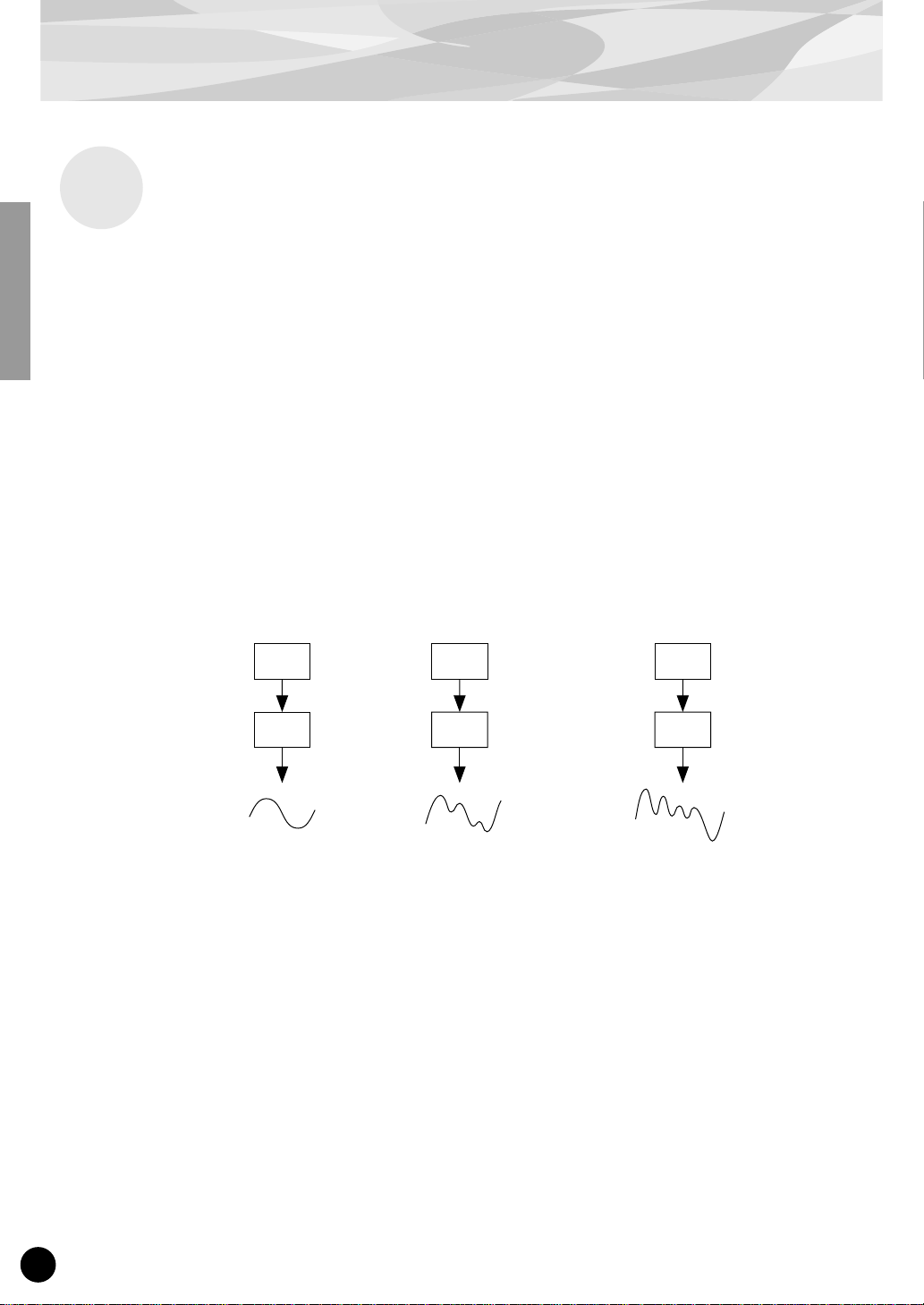
In the PLG150-DX, there are six special devices called “operators” that generate sine waves. A sine
wave is the fundamental wave of a note, with absolutely no overtones or harmonics added. These six
operators are combined in various ways to make up the dif ferent v oices produced by the PLG150-DX.
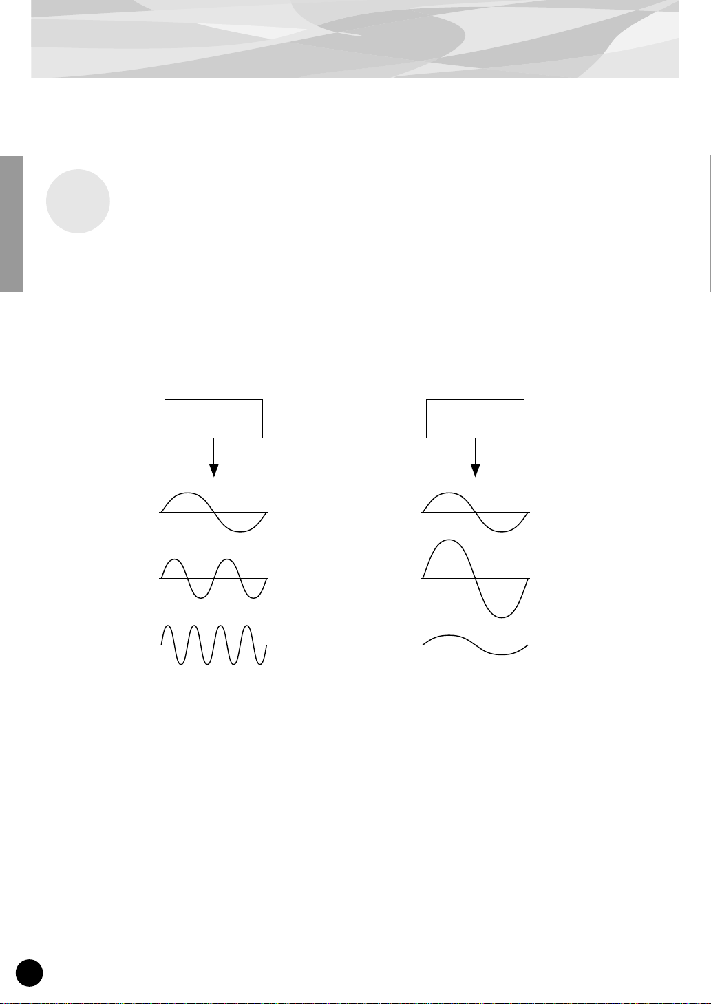
The operators can be used to freely change two different aspects of the sound:
(1) The frequency (pitch) of the generated sine wave.
(2) The amplitude (volume or output level) of the generated sine wave.
Operator Operator
The frequency of the
sine wave is changed.
This results in the pitch
becoming higher or
lower.
The amplitude of the
sine wave is changed.
This results in the volume
becoming higher or lower.
6
Page 7
Combinations of Two Operators
Although the six operators can be combined in a wide variety of ways for many dif ferent sounds, here
we’ll look at the fundamental combinations of just two operators, to help you understand the basics of
FM synthesis.
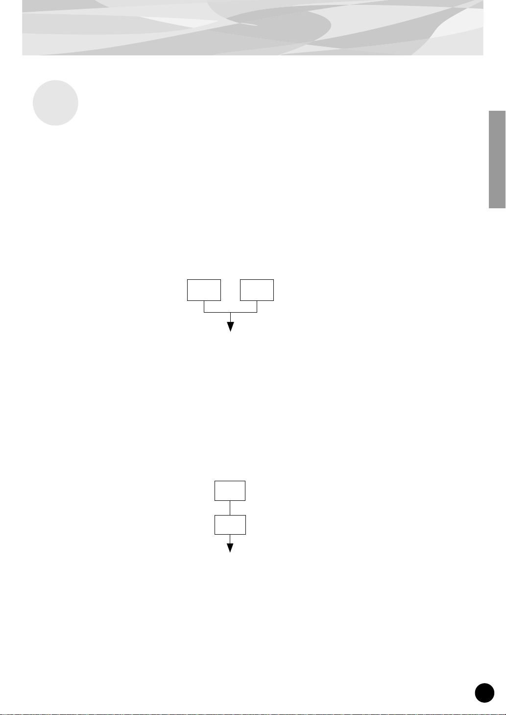
Two sine wave operators (labelled “A” and “B” here) can be combined in one of two ways: horizontally or vertically.
(1) Horizontal Combination
When the two operators are combined horizontally, the sounds of the two are simply mixed together.
This combining of two or more different sounds is called additive synthesis.
FM Tone Generation
A B
Mixed sound of A and B
(2) Vertical Combination
When the two operators are combined vertically, the sound of the top operator (B) “modulates” that of
the lower operator (A). In this situation, operator B produces no sound, but alters the sound of operator A, producing a sound of greater harmonic complexity. This “stacking” of operators is called Frequency Modulation (FM) synthesis.
Operator B changes or modulates the sound
B
of A (but produces no sound itself).
Operator A produces the actual sound, as
A
modulated by B.
T o sum it up, when tw o operators are combined horizontally, both operators generate the sound; when
combined vertically, one operator changes the sound, the other produces it.
7
Page 8

FM Tone Generation
Carrier and Modulator
In FM tone generation, each of the six operators functions as either a carrier or a modulator. The
operator doing the modulation is called the modulator; the one being modulated and delivering the
actual sound is called the carrier. Referring back to “Vertical Combination” on the previous page,
operator A is the carrier and operator B is the modulator.
Let’s take a look at some more complex configurations, in which three or more operators are used.
Keep in mind that the modulator/carrier function is the same in all examples.
fig. 1
C C C
fig. 5
fig. 2
M
M
fig. 3 fig. 4
M
C
C
M M
C
C
M M
C C
“C” Carrier
“M” Modulator
●
In fig. 1, all operators are combined horizontally and there are no modulators, only carriers. Without modulation, all carriers output simple sine waves.
●
In fig. 2, three operators are stacked vertically, and only the lowest is a carrier. The top operator
modulates the middle one, which in turn modulates the carrier at the bottom. This results in a complex waveform, with many harmonics or overtones. (An explanation of harmonics follows on the
next page.)
●
In fig. 3, there are two carriers and one modulator. The sole carrier on the right produces a simple
sine wave, while the modulator/carrier pair on the left produce a more complex waveform with
added harmonics. The actual sound is a mix of the two carriers.
●
In fig. 4, two modulators are used change the sound of a single carrier. Using two modulators produces an even more complex sound than is possible with one, with a greater amount of harmonics.
●
In fig. 5, there are two modulator/carrier pairs, each generating a complex sound with many harmonics. As with the operators in fig. 3, the actual sound is a mix of the two carriers.
8
Page 9
Harmonics
Most sounds are made up of multiple tones that are different than the pitch (frequency). Within these
multiple tones, the one that determines the pitch of the entire sound is called the fundamental tone
(fundamental frequency). All the tones besides the fundamental tone are called harmonics or overtones.
When all the harmonics that are related to a particular fundamental tone are arranged in order, it is
called a harmonic series. Each tone in the harmonic series is given a name in order, with the fundamental tone being one, followed by the second harmonic, third harmonic and so on.
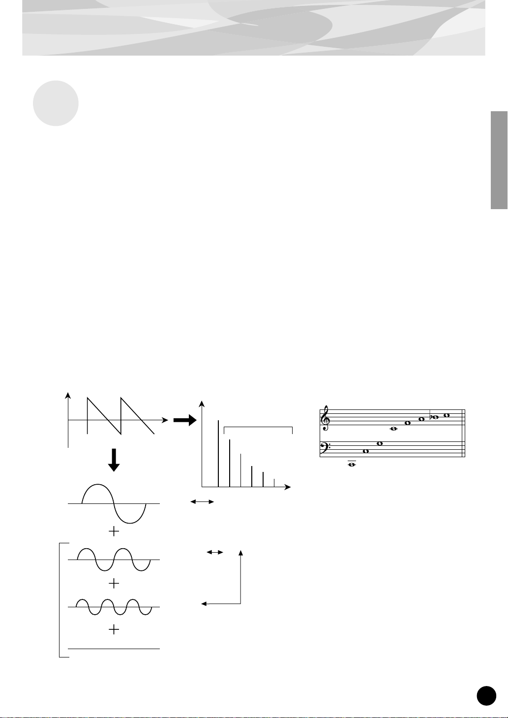
The frequency of each harmonic in the harmonic series is a natural number multiple of the frequency
of the fundamental tone. Overtones that have frequencies that are not natural number multiples of the
fundamental are called unharmonic overtones.
FM Tone Generation
Generally, the more harmonics the tone has, the brighter the sound. On the other hand, if the amount
of harmonics is reduced, the tone will sound darker. Furthermore, the voice will change a lot according to the type and volume of the harmonics. For example, if there are a lot of high pitched harmonics
in the tone, it will have a brilliant, crisp sound. On the other hand, a tone with a large amount of lower
harmonics will have a rather “fat,” warm sound.
Harmonics
Level
Waveform
Fundamental Wave
Second Harmonic
Time
Level
Fundamental and
Harmonics (graph)
Harmonics
Fourth Harmonic
Third Harmonic
Second Harmonic
Fundamental
Frequency
Natural Harmonic Series
(when C1 is the fundamental tone)
Fifth Harmonic
Fourth Harmonic
Third Harmonic
Second Harmonic
Fundamental
Sixth Harmonic
Seventh Harmonic
Eighth Harmonic
Harmonic
Third Harmonic
9
Page 10
FM Tone Generation
Algorithms
Although two operators can be combined in only two different ways, six operators can be configured
in a wide variety of combinations. These combinations are called “algorithms.” Just as on the original DX7, the PLG150-DX features 32 different algorithms, giving you different levels of harmonic
complexity for various applications.
Since the function of any given operator depends on the particular algorithm, you should check a
voice’s algorithm carefully while editing the voice. For a chart showing all 32 algorithms, see page
34. Each operator in the algorithm is numbered to distinguish it from the others in editing.
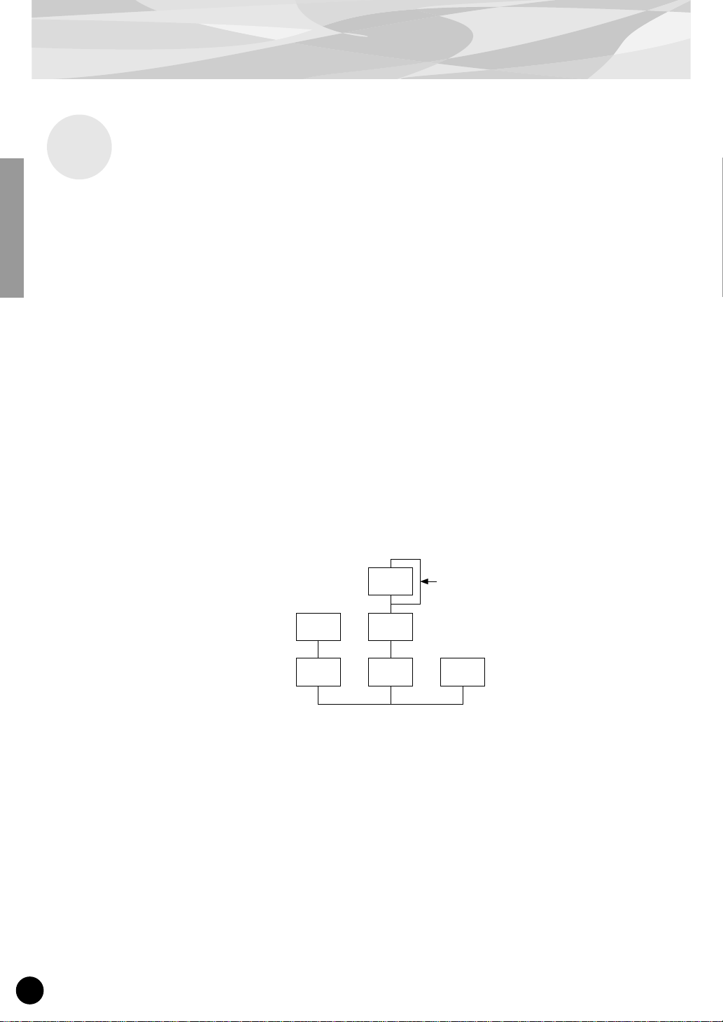
Let’s take a look at algorithm 28 as an example. The various operators function as follows:
Operator 1.............Carrier; is modulated by Operator 2, and outputs the resulting sound.
Operator 2.............Modulator; modulates Operator 1.
Operator 3.............Carrier; is modulated by Operator 4, and outputs the resulting sound.
Operator 4.............Modulator; modulates Operator 3.
Operator 5.............Modulator; modulates itself with a feedback loop, and modulates
Operator 6.............Carrier; outputs a sine wave.
Operator 4.
Algorithm 28
2 4
1 3 6
5
Feedback loop
(see next section)
10
Page 11
Feedback
Each algorithm has a special feedback loop, programmed to a fixed location in the algorithm. With
feedback, a modulator’s output is connected to its own input, so that it modulates itself. This can be
used to increase the harmonic content of the sound, making it more rich and complex. When set to a
high level, feedback can generate noise effects — making it useful for percussive voices, metallic
sounds, and distortion effects.
Some algorithms feature a feedback loop that takes in two or three operators as a group. One such
example is algorithm 4 shown below, in which the output of operator 4 is returned to the input of
operator 6, thus modulating the entire stack. This provides even greater possibilities for tonal variation and richness.
FM Tone Generation
Algorithm 4
3
2
1
6
5
4
Feedback loop
11
Page 12
FM Tone Generation
Voice Editing Essentials
There are four main elements that determine the character of a voice:
(1) Each operator’s output level.
(2) Each operator’s frequency.
(3) The feedback level.
(4) Each operator’s envelope generator (EG).
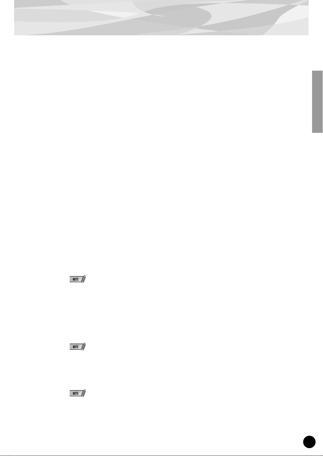
(1) Operator Output Level
The output levels of the operators are the most important parameters in editing a voice. Among these,
the output level of the modulator(s) has the greatest effect on the timbre or tonal quality of the voice.
If a modulator’s output level is set to “0” so that it does not modulate the carrier, the resulting output
of the carrier will be a simple sine wave (belo w). Increasing the output of the modulator increases the
degree of modulation and, hence, the amount of harmonics in the sound. Generally, the greater the
modulator’s output, the brighter the sound will be. Extremely high values result in a harsh, noisy
sound.
Modulator
Carrier
Since the carrier actually produces the sound, increasing the output level of a carrier increases the volume of the sound. If there are two or more carriers, changing the output level of individual carriers
may also affect the timbre of the sound, since the volume balance of the different carriers is changed.
B
Output Level = 0
A
Sine wave The waveform changes
B
The output level is
increased slightly.
A
slightly.
B
The output level is
greatly increased.
A
The waveform changes a lot.
(2) Operator Output Frequency
The type of harmonics added to the carrier output by means of the modulator is determined by the
ratio between the frequencies of the modulator and carrier. F or e xample, when two operators are combined vertically, and “F COARSE” for both of them is set to 1.00, the frequency ratio will be 1:1 and
the first, second, third and following whole number series harmonics will be generated in order. This
type of harmonic configuration is called a sawtooth wave, and is used for making voices like brass,
strings, or piano.
12
Page 13

FM Tone Generation
If the “F COARSE” for the modulation in this situation is changed to 2.00, the frequency ratio
becomes 1:2, and the odd numbered harmonics, the first, third and fifth and following harmonics will
be generated. This harmonic configuration is called a rectangular wave, and is used for creating w oodwind voices for like clarinet and oboe.
Furthermore, if “F FINE” is set so that the frequency ratio is not a whole number, many non-integer
overtones will be produced. The sound can be used for creating metallic sounds, the noise when
strings are hit with something, or breath noise.
Modulator
Carrier
B
Frequency
ratio 1:1
A
Sawtooth wave Rectangular wave
B
Frequency
ratio 1:2
A
(3) Feedback Level
As we saw earlier, feedback is a function in which a modulator’s output is connected to its own input,
so that it modulates itself. Increasing the feedback level increases the harmonic content of the sound,
making it brighter and complex. Keep in mind that the total effect also depends on the output level of
the feedback-applied operator; if that operator’s output level is set to “0,” feedback level will have no
affect on the sound.
(4) EG (Envelope Generator)
The EG (Envelope Generator) parameters allow you to shape the sound of the voice. In other words,
these determine how the level of the voice changes over time, from when a key on the keyboard is
played until it is released and the sound dies out.
The EG parameters let you reproduce the sound of acoustic instruments, and their natural patterns of
attack, sustain and decay. For example, the sound of a piano has a very sharp attack and a moderately
long sustain: The sound gets loud the instant a key is played, and gradually fades away as the key is
held. The tone or timbre of the sound also changes in time, with the sound starting out very bright and
gradually growing warmer and softer (as the harmonics start to fade).
Since each operator has its own EG, the PLG150-DX gives you comprehensive and dynamic control
over both the volume and timbre of the voice, letting you accurately reproduce these natural acoustic
effects. The carrier EGs af fect the volume of the sound over time, while the modulator EGs affect the
timbre.
13
Page 14
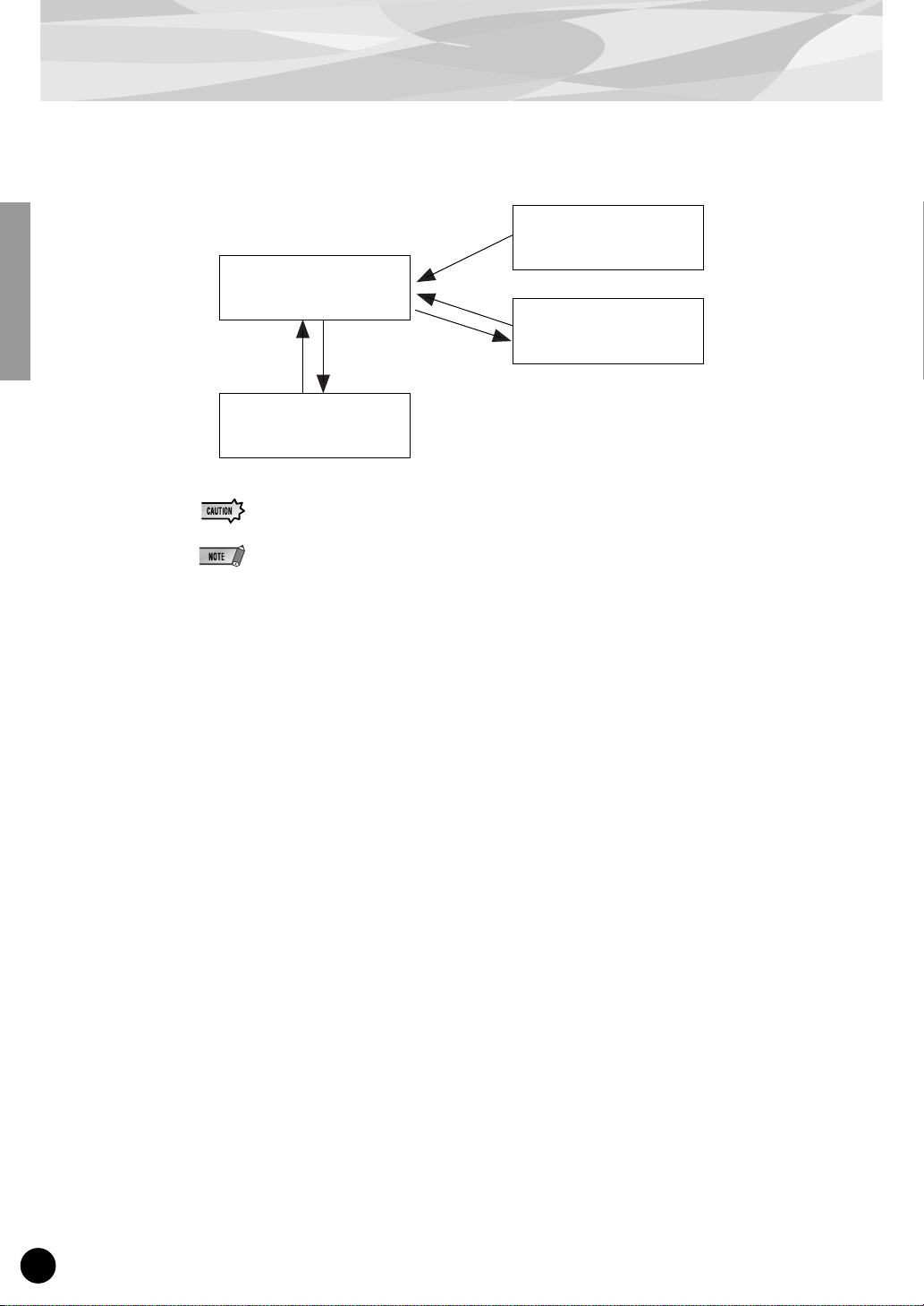
Memory Buffer Structure
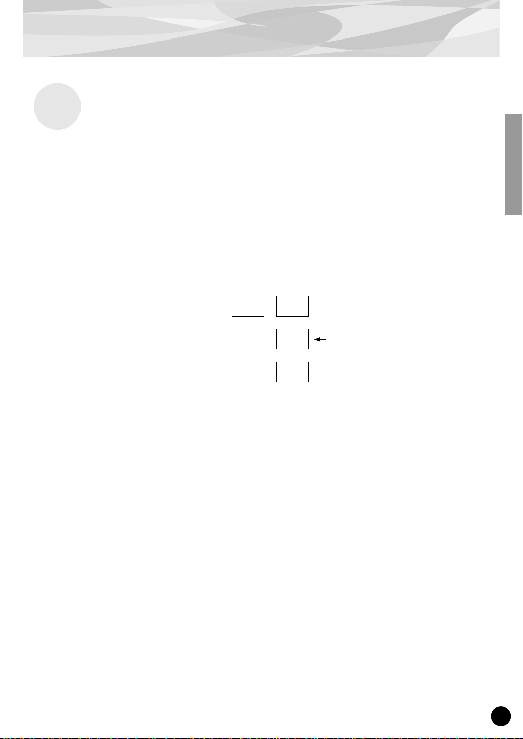
The diagram below shows the memory buffer configuration of the PLG150-DX.
Recall
Voice Edit Buffer
Compare
Edit Recall
Edit Recall Buffer
When editing the voices (using the DX Simulator), only the User voices can be fully edited; Preset voices can be edited only as far as the XG and DX Native Part parameters.
When Using the User voices:
• When a DX voice is selected from one of the User voices, the DX voice’s settings for the following
parameters take precedence over the corresponding settings.
XG Native Part Parameters
Mono/Poly Mode
Pitch Bend Control
Portamento Switch
Portamento Time
PLG150-DX Native Part Parameters
Pitch Bend Step
Portamento Step
Portamento Mode
In other words, the settings of these XG Part parameters (on an MU128, etc.) are replaced by those
of the selected DX voice. Naturally, once the voice is selected, the Part parameter values can then
be changed from the panel of the XG-compatible “mother” device (MU128, etc.). The XG Native
Part parameters can also be changed by appropriate parameter change messages.
• If an XG System On is received, or part assignment is changed, the User voices will be initialized,
but the 64 voice VMEM and AMEM areas will not be initialized.
Store
Preset Memory
(912 Voices)
User Voices
(64 Voices)
14
Page 15

Specifications
Tone Generator Type : FM tone generator with six operators and 32 algorithms
Maximum Simultaneous Polyphony :
Filters : Part EQ (two band), low pass filter, high pass filter (effective only when
Interface : Plug-in connector
Number of Voices : 912 preset voices, 64 user voices
Bulk Information that Can Be Received from Other Devices :
Parameter Changes that Can Be Received from Other Devices :
16 notes (latest note priority)
By using multiple boards in combination, polyphony can be expanded to
a maximum of 128 notes (with 8 boards)
the platform for the PLG150-DX has no filter functions)
DX7 Voice Edit Buffer, Packed 32 Voice
DX7II Voice Edit Buffer, Packed 32 voice, a portion of the Additional
Edit Buffer, a portion of the Packed 32 Additional (Pitch EG
range, rs, velocity switch, Unison detune, AMS, Random pitch,
Poly/Mono, Unison Sw, Pitch bend range, step, Portamento
mode, step, time)
DX7 VCED, a portion of ACED (Pitch EG range, rs, velocity switch, Unison detune, AMS, Random pitch, Poly/Mono, Unison Sw, Pitch bend
range, step, Portamento mode, step, time)
Dimensions (W x H x D) : 138.5 x 89.0 x 8.5mm
Weight : 63g
Included Items : Owner’s Manual, CD-ROM × 1
* Specifications subject to change without notice.
15
Page 16

About the Included CD-ROM and Floppy Disk
On the included CD-ROM, you’ll find special editing software for the PLG150-DX. The included
floppy disk contains demonstration songs as well as V oice/Performance data for the “mother” device.
To use the editing software and transf er the song/Voice/Performance data to your particular “mother”
device, you should have a computer (running Windows 95/98) with a MIDI interface, with the MIDI
OUT on the interface connected to the MIDI IN of the “mother” device. You should also have
XGworks (v3.0 or higher) or XGworks lite installed to your computer; this is necessary to use the
editing software (page 19). In order to use the editing software, insert the CD-ROM into the computer and start the installation.
For playing bac k the demonstr ation songs and tr ansferring the Voice/Performance data, you can use
any compatible sequence software (such as XGworks/XGworks lite) or hardware sequencer capable of sending bulk data.
The included CD-ROM contains the following software:
■ DX Easy Editor (page 19)
■ DX Simulator (page 19)
The included floppy disk contains the following software:
■ Demonstration Songs
“Many Colors of the DX7 system” (02Colors.MID)
By: Hirohiko Fukuda of Shofuku
For: Modular Synthesis Plug-in System devices (CS6x, etc.)
One of the strongest points of FM Synthesis is its ability to create complex overtones in real time. In this
song, system exclusive messages are used, in addition to velocity, to directly control the output of the
modulators. This creates an even greater variety of sound changes — allowing complex sound shaping
that just isn’t possible through wave sampling and conventional filter systems.
16
“The Soul Of DX” (12SoulDX.MID)
By: Minoru Mukaiya of Casiopea
For: XG Plug-in System devices (MU128, etc.)
This powerful song uses the crystal-clear sound of the DX7 with techno drums, and combines the XG
and DX systems to produce an extraordinarily dynamic sound.
“Ie Kia Bara Hein” (12IeKia.MID)
By: Noritaka Ubukata of Shofuku
For: XG Plug-in System devices (MU128, etc.)
The title of the song means “What kind of spell is this?” in the Hindi language. It features the voice that
simulates a santur (hammer dulcimer) together with a sitar.
“DX VOICE” (12Voice.MID)
By: Noritaka Ubukata of Shofuku
For: XG Plug-in System devices (MU128, etc.)
Starting with an electric piano sound, this song features a variety of popular voices used with the original
DX7. The changes in velocity produce subtle variations in the sound that cannot be accomplished with
sampling. Another special feature is the FM choir (starting around measure 43). You may want to try
mix this sound with an actual human voice or choir — for example, by using the data in track 1 to also
play a connected sampler — you can get a much more dynamic and realistic choir sound.
“Vel&EffectWorks1” (12V_EfW1.MID)
“Vel&EffectWorks2” (12V_EfW2.MID)
“DX Short Demo” (12ShtDM.MID)
By: Yasuhiko Fukuda of Shofuku
For: XG Plug-in System devices (MU128, etc.)
These songs showcase the unique ability of FM Synthesis to use velocity to produce dramatic changes in
the sound.
Page 17
About the Included CD-ROM and Floppy Disk
“80’s Pops” (12Pop80.MID)
By: Katsumi Nagae of Idecs Inc.
For: XG Plug-in System devices (MU128, etc.)
This song recalls the pop scene of the 80’s with synth pads and a variety of crisp and bright metallic
sounds.
“D-Rock” (12DRock.MID)
By: Katsumi Nagae of Idecs Inc.
For: XG Plug-in System devices (MU128, etc.)
This song brings back the digital rock sound and features various digital noise and FM sound effects that
are only possible with the DX.
“EP Ballade” (12Ep.MID)
By: Katsumi Nagae of Idecs Inc.
For: XG Plug-in System devices (MU128, etc.)
If it’s ballads you want-well, there is nothing like DX electric piano.
The voice in the electric piano part will also work with different electric pianos. Try playing the song
with different piano voices.
“House” (12House.MID)
By: Katsumi Nagae of Idecs Inc.
For: XG Plug-in System devices (MU128, etc.)
The typical house music sound is simulated in this song, which experiments with reproducing sampling
phrases using the DX Voice system. In addition, the second half of the song features the metalic sound
that is a strong point of the DX.
“Jungle” (12Jungle.MID)
By: Katsumi Nagae of Idecs Inc.
For: XG Plug-in System devices (MU128, etc.)
This song adds a touch of Chinese feeling to the Jungle. The Oriental image is underscored by the
“CHINA_S&” and “IMAGE9” plug-in SE voices.
If no sounds are played, or if you experience other problems with playback, see Appendix “When Your
PLG150-DX Seems to Have a Problem.”
■ Plug-in Voice Data for the CS6x/CS6R/S80
(Modular Synthesis Plug-in System)
This is Plug-in voice data, featuring a total of 64 voices that were created using the PLG150-DX Preset voices.
When the PLG150-DX is installed to PLG1, select the file “01PlgVc1.mid”; when the board is installed to PLG2,
select the file “01PlgVc2.mid”.
For a complete list of these voices, refer to the Plug-in Voice List in the Owner’s Manual.
■ Performance Data for the MU128/MU100/MU100R (XG Plug-in System)
This is Performance data, featuring a total of 64 Performances that were created using the PLG150-DX Preset
voices (“11Perf.MID”).
For a complete list of these Performances, refer to the Performance List in the Owner’s Manual.
17
Page 18

Installing the PLG150-DX
For detailed instructions on installing the PLG150-DX, refer to the owner’s manual of the Plug-incompatible “mother” device (e.g., CS6x, MU128, etc.).
Included Items
The following items have been included in the package of your new PLG150-DX. Please make sure
that you have them all before starting to setup and use the instrument. If an item is missing, contact
the store or dealer from which you purchased the PLG150-DX.
• PLG150-DX board
• PLG150-DX Owner’s Manual (this book)
• CD-ROM
• Floppy Disk
Required and Recommended Items
In addition to the included items listed above, you should also have the following:
Synthesizer/Tone Generator/Sound Card Compatible with the Modular Synthesis or XG Plug-in Systems
In order to use the PLG150-DX, you’ll need a synthesizer, tone generator or sound card compatile
with the Modular Synthesis Plug-in System or the XG Plug-in System. Compatible instruments
include the CS6x, MU128, and the SW1000XG. The synthesizer/tone generator/sound card should
also have an available slot or space for installing the PLG150-DX.
18
Page 19

Required and Recommended Items
XGworks or XGworks lite Music Sequencing Software
When you use Yamaha’s XGworks(lite) as your sequence software, you can take advantage of the two
editing software programs explained below, the “DX Simulator” and the “DX Easy Editor.” These
programs make it really easy to edit the voices of your PLG150-DX board.
DX Easy Editor
The DX Easy Editor is a special plug-in software module for XGworks and XGworks lite. It provides
convenient easy-to-use control over the most important PLG150-DX settings and parameters. It also
provides exceptionally intuitiv e editing, with virtual sliders and b uttons, as well as special graphs with
click-and-drag operation.
Using the DX Easy Editor is just like using the Part editing controls on your tone generator — it indirectly and temporarily changes the DX voices without making changes to the original voice. The
changed parameters can either be inserted into a song to automate sound changes, or can be saved as a
DX Parameter file for future recall. Continuous real-time parameter changes can be recorded to a song
as well. The DX Easy Editor software is contained on the included CD-ROM.
DX Simulator
As with DX Easy Editor above, the DX Simulator is special software for use with XGworks and
XGworks lite. It allows you to directly edit all of the DX voice settings and parameters from your
computer. It also provides exceptionally intuitive editing, with a virtual “front panel” display that lets
you change the settings with buttons and sliders, just as you would on an actual DX7. It also features
a special Edit List window, that lets you quickly and easily edit all parameters from one convenient
chart.
More comprehensive than the DX Easy Editor above, the DX Simulator gives you convenient access
to all of the PLG150-DX’s parameters, controls and functions. The changed parameters can either be
inserted into a song to automate sound changes, or can be saved as a DX Cartridge file for future
recall. Continuous real-time parameter changes can be recorded to a song as well. It also lets you save
your edits directly as a User voice for future recall. The DX Simulator software is contained on the
included CD-ROM.
19
Page 20
Installing and Starting the Plug-in Editor Software (Windows 95/98)
Installing the Software
Double-click the “Setup.exe” file on the CD-R OM to start the installation. Click “Ne xt” or “Yes” and
follow the subsequent instructions on the screen to complete the installation.
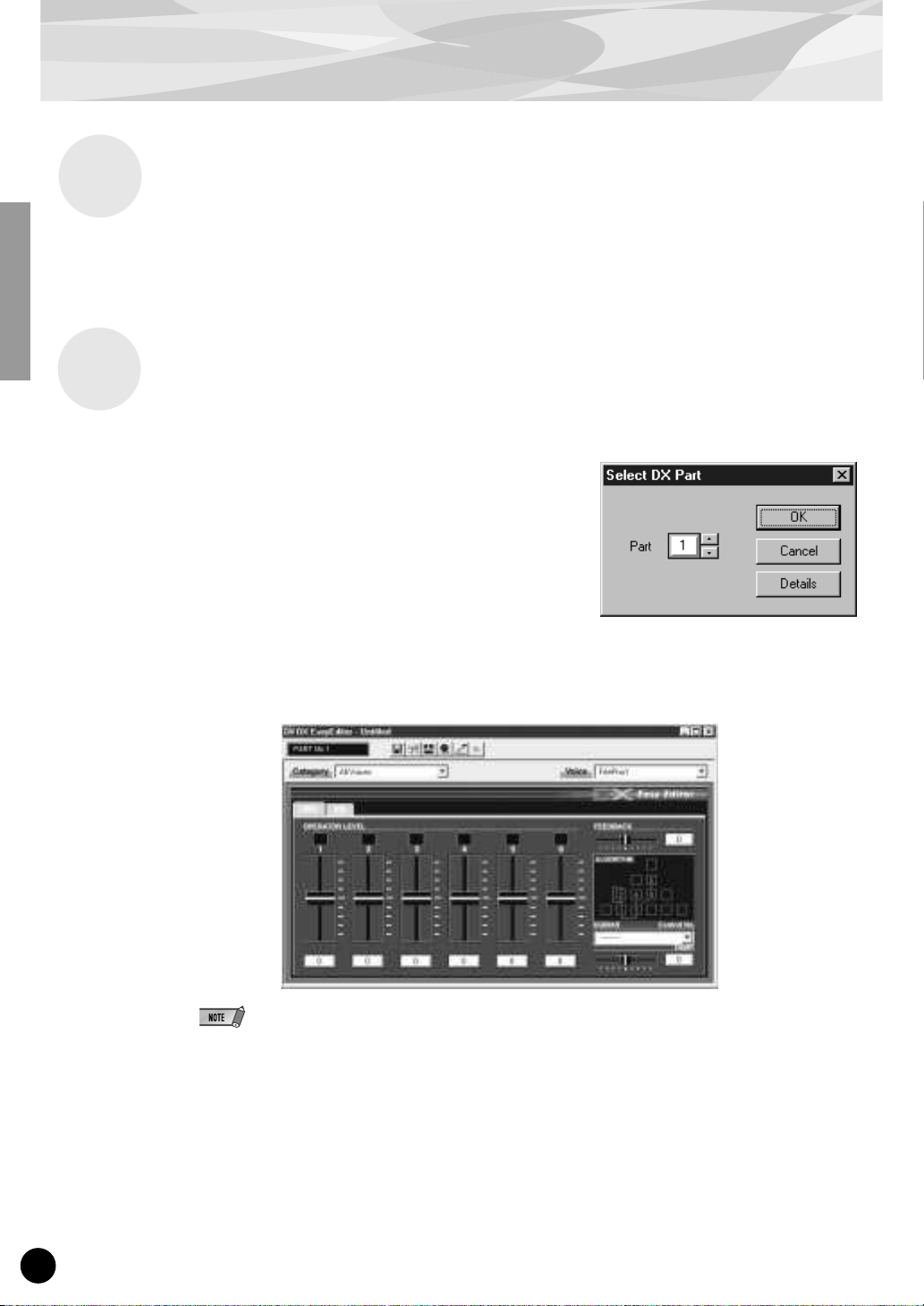
Starting the DX Easy Editor
1 Start XGworks (or XGworks lite).
2 Click the “Plug-in” menu and select “DX
Easy Editor.”
Alternately, press Alt + P, then D, and ENTER. The
“Select DX Part” dialog box appears.
3 Set the desired Part number and click “OK.”
The DX Easy Editor window appears.
If the PLG150-DX has been properly installed and all computer/MIDI connections have been
properly made, operating the DX Easy Editor should directly affect the PLG150-DX. For details
on using the DX Easy Editor, refer to the on-line help file that is included with the software.
When using a Modular Synthesis Plug-in System “mother” device, the Part assignment depends on
which mode is used — Voice or Performance — and also on whether the PLG150-DX board is
installed/assigned to PLG1 or PLG2, as described below.
When using the Voice mode:
Depending on which slot the PLG150-DX board has been installed to, press PLG1 or PLG2, then
set the Part to “1” (no matter what the PLG1 or PLG2 assignment is).
When using the Performance (Multi) mode:
If the PLG150-DX board is assigned to PLG1, set the Part to “16.”
If the PLG150-DX board is assigned to PLG2, set the Part to “15.”
20
Page 21
Installing and Starting the Plug-in Editor Software (Windows 95/98)
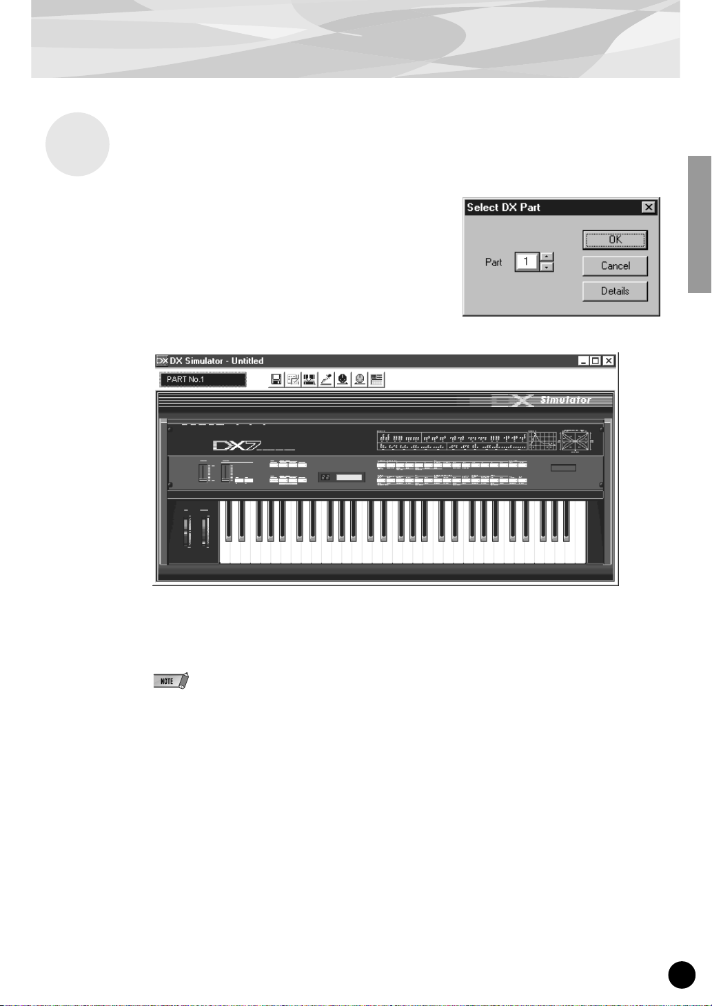
Starting the DX Simulator
1 Start XGworks (or XGworks lite).
2 Click the “Plug-in” menu and select “DX
Simulator.”
Alternately, press Alt + P, then D, and ENTER. The
“Select DX Part” dialog box appears.
3 Set the desired Part number and click “OK.”
The DX Simulator window appears.
If the PLG150-DX has been properly installed and all computer/MIDI connections have been
properly made, operating the DX Simulator should directly affect the PLG150-DX. For details
on using the DX Simulator, refer to the on-line help file that is included with the software.
● To use the DX Simulator, your copy of XGworks must be version 1.05 or later.
You can download the proper update of XGworks or XGworks lite from the Yamaha website
(http://www.yamaha.co.uk).
● When using a Modular Synthesis Plug-in System “mother” device, the Part assignment depends on
which mode is used — Voice or Performance — and also on whether the PLG150-DX board is
installed/assigned to PLG1 or PLG2, as described below.
When using the Voice mode:
Depending on which slot the PLG150-DX board has been installed to, press PLG1 or PLG2,
then set the Part to “1” (no matter what the PLG1 or PLG2 assignment is).
When using the Performance (Multi) mode:
If the PLG150-DX board is assigned to PLG1, set the Part to “16.”
If the PLG150-DX board is assigned to PLG2, set the Part to “15.”
21
Page 22

Selecting DX Voices (Modular Synthesis Plug-in System)
When the PLG150-DX is installed to a CS6x Control Synthesizer, the DX voices can be selected in
the same way as the internal voices of the synthesizer.
The example displays used in the following explanations are all taken from the CS6x.
Enabling and Selecting DX Voices
1 Press the VOICE button.
2 Press the appropriate PLG button (PLG1 or PLG2, depending on which
slot the PLG150-DX board has been installed to), then press the appropriate BANK button and PROGRAM button to select the desired Plug-in
voice.
VCE Play) PLG1:001(A01)[--:Plig-InVce]
EQLow-G EQMid-G EQHi-G ------- -------
To select a different bank, simultaneously hold down the appropriate PLG button and turn knob C (or
press the DEC/INC buttons) to select the desired bank.
The bank is expressed in two numbers: MSB and LSB.
VCE Play) P1-B:001(A01)[--:MM-Pno 1 ]
BANK= 083/065
If a selected bank is not available, the bank letter indication in the display (A - H) will not change.
For a list of the available banks and their MSB/LSB values, refer to the “DX-XG Voice Map” at
the back of this manual.
22
Page 23

Editing the DX Native Part Parameters (Modular Synthesis Plug-in System)
● Keep in mind that the parameter values and settings below represent offsets of the actual voice settings. This
means that adjustments made to the parameters may not make much change in the actual sound, depending
on the original settings of the voice. For parameter values, a setting of “0” results in no change, while positive
and negative values increase and decrease the value respectively.
● The following explanations show how to edit the DX native part parameters when creating PLG voices, using
the CS6x Control Synthesizer as an example. For information on storing the PLG voices with your particular
Modular Synthesis Plug-in System compatible instrument, refer to the owner’s manual of that instrument.
1 Select the desired DX voice, as described in “Selecting DX Voices” on
page 22.
2 Press the EDIT button.
The EDIT menu display appears.
GEN Name) Ctgry a-Z 0-? Cursor
Common [--:MM-Pno 1 ]
3 Turn knob A clockwise until “Elem” is shown at the bottom left of the dis-
play.
OSC Assign) Bank Number
Elem 083/065 1[MM-Pno 1]
4 Turn the PAGE knob clockwise until “PLG150-DX” is shown at the bottom
left of the display.
Keep turning the knob to select the different DX Part parameters, indicated just abo ve knob C and
knob 2.
NTV Param) Carrier1 Carrier2
PLG150-DX +00 ***
5 Use knobs C and 2 to select the desired parameter and change the value.
Once one of the parameters is selected (the arrow cursor appears next to the value), you can also
adjust the value with the DATA knob or the DEC/INC buttons.
● In order to store User voices on a Modular Synthesis Plug-in System compatible instrument that
have been edited/created with the computer-based DX Simulator (or with the compatible instrument
itself), you’ll need to use an external memory device , such as a memory card. For details on storing
voices, refer to the owner’s manual of your Modular Synthesis Plug-in System compatible instrument.
● The actual parameter names may differ, depending on whether the instrument you are using is XG
Plug-in System compatible or Modular Synthesis Plug-in System compatible. For details, refer to
the Parameter List (XG / Modular Synthesis Plug-in System).
23
Page 24

Selecting/Editing the DX System Parameters (Modular Synthesis Plug-in System)
The example displays used in the following explanations are all taken from the CS6x.
1 Press the UTILITY button.
The Utility Mode display appears.
MSTR TG) Vol NoteShift Tune
Sys 127 + 0 + 0.0c
2 Turn the PAGE knob clockwise until “PLG150-DX” is shown at the bottom
left of the display.
Keep turning the knob to select the different DX System parameters, indicated just above knob C
and knob 2.
PLG1 System) BulkBlock VelCurve
PLG150-DX 01-32 Normal
3 Use knobs C and 2 to select the desired DX System parameter and change
the value.
Once one of the parameters is selected (the arrow cursor appears next to the value), you can also
adjust the value with the DATA knob or the DEC/INC buttons.
24
Page 25

Selecting DX Voices (XG Plug-in System)
The PLG150-DX voices can be selected just like the v oices of the XG tone gener ator. Keep in mind,
though, that they can only be selected when the Sound Module Mode is set to XG or Performance.
Also, the Part Assign parameter in the Utility mode (see below) must be set to the desired Part.
The example displays used in the following explanations are all taken from the MU128.
Enabling and Selecting DX Voices
1 Set the Sound Module Mode to “XG” or “PFM” (Performance).
Press the MODE button and use the SELECT </> buttons.
The Performance mode is not available on the SW1000XG.
2 Set the Part Assign parameter to the desired Part number.
To do this:
1) Press the UTIL button.
2) Select the “PLUGIN” menu (with the SELECT > button) and press ENTER.
3) Select the “PLG150-DX” menu if necessary (with the SELECT </> buttons), and press
ENTER.
4) Select the Part Assign parameter (with the SELECT
tons or dial to change the Part number.
< button), and use the VALUE -/+ but-
The Part Assign range for the XG mode is 1 - 16 and “off”; for the Performance mode, it is 1 - 4 and
“off.”
Press the EXIT button to return to the Play mode.
This operation can also be quickly and conveniently done from the DX Easy Editor or DX Simu-
lator (in XGworks).
3 Enable the PLG150-DX board for the desired Part.
First, make sure that the appropriate Part is selected (using the PART -/+ buttons), then press the
SELECT button. The icon of the selected board appears in the display and the corresponding
LED at the bottom of the panel (PLG-1, -2, or -3) flashes briefly.
25
Page 26

Selecting DX Voices (XG Plug-in System)
4 Select the desired bank number.
Move the cursor to the Bank Number parameter with the SELECT </> buttons and use the
VALUE -/+ buttons to select the desired bank.
5 Select the desired voice number.
Move the cursor to the Voice (Program) Number parameter with the SELECT </> buttons and
use the VALUE -/+ buttons to select the desired voice.
Voices (and Voice banks) can also be selected by using the Voice Category buttons.
Alternately, you can select v oices from a connected MIDI ke yboard, or from sequencing software
(such as XGworks) on a connected computer.
Bank Number parameter
For a list of available voices and their bank/voice numbers, see page 36.
26
Page 27

Editing the DX Native Part Parameters (XG Plug-in System)
Any of the DX voices can be freely edited from the front panel with the DX Par t parameters. These
same parameters can also be edited from a computer using the DX Easy Editor software (in
XGworks).
Keep in mind that changing the Par t parameters does not permanently affect the original voice settings. The edits that you make here temporarily change the settings of the currently selected voice.
When you select a different voice for the Part, the settings are applied to the newly selected voice.
● The Part parameter settings cannot be saved in Multi Play mode. If you wish to save your Part parameter
edits, do it from the Performance mode or the DX Easy Editor. If y ou wish to save your edits to a voice, use the
DX Simulator software to edit the parameters of a voice, then save it as a User voice.
● The example displays used in the following explanations are all taken from the MU128.
1 Select the Part having the DX voice, then select the desired voice.
Select the appropriate Part with the PART -/+ buttons, then, with the cursor at the Voice Number
parameter, select the desired voice.
2 Press the EDIT button to enter the Edit mode.
3 Select the “PLUGIN” menu.
Use the SELECT > button, then press the ENTER button. The PLG150-DX Edit menu appears.
4 Select the desired parameter.
Use the [SELECT </>] buttons.
5 Adjust the value or change the setting for the selected parameter.
Use the [VALUE +/-] buttons.
6 Return to the main Play display.
Press the [EXIT] button several times, or press the [PLAY] button once.
27
Page 28

Selecting/Editing the DX System Parameters (XG Plug-in System)
The parameters that apply to the entire system of the PLG150-DX are included in the Utility mode
menu of the XG tone generator.
The example displays used in the following explanations are all taken from the MU128.
1 Press the [UTIL] button.
The Utility mode menu appears.
2 Select the “PLUGIN” menu.
Use the [SELECT >] button to highlight “PLUGIN,” then press the [ENTER] button.
3 Select the PLG150-DX board.
If the PLG150-DX board is the only one installed, “PLG150-DX” is already displayed and can be
selected by pressing the [ENTER] button. If additional boards have been installed to the tone
generator, you may need to select “PLG150-DX.” To do this, first use the [SELECT </>] buttons, then press [ENTER].
The System parameter menu for the PLG150-DX appears.
4 Select the desired parameter.
Use the [SELECT </>] buttons.
5 Adjust the value or change the setting for the selected parameter.
Use the [VALUE +/-] buttons.
6 Return to the main Play display.
Press the [EXIT] button several times, or press the [PLAY] button once.
28
Page 29

Parameters
DX Native Part Parameters
Keep in mind that the parameter values and settings represent offsets of the actual voice settings. This
means that the actual sound that results from the settings made here depends on the original settings
of the voice.
Also keep in mind that these are “Part” parameters and as such, are temporary; they simply alter or
offset the settings of the currently selected voice. The original voice settings are permanently maintained in memory.
For parameter values, a setting of “0” results in no change, while positiv e and ne gati v e v alues increase
and decrease the value respectively.
Let’s look at a specific example. If the original Feedback Level parameter of the selected voice is set
to +2, and you set the Feedback Level (below) to “-4,” the actual Feedback Level will become “-2.” If
you set it to “+1, ” the v alue will become “+3.” Naturally, this also means that the parameter value cannot be increased or decreased beyond its maximum or minimum values. In our example, Feedback
values higher than “+5” have no effect on the sound, since the actual range is -7 — +7.
● Depending on the selected voice and the particular parameter being edited, the sound or actual
parameter value of certain voices may change very little or not at all, even when the parameter v alue
is changed drastically.
● For Modular Synthesis Plug-in System compatible devices, the voices you edit/create can be stored
to the device as PLG voices. For details on storing voices, refer to the owner’s manual of your Modular Synthesis Plug-in System compatible instrument.
■ Carrier1 — Carrier6 (Carrier Operator 1 — 6 Level)
Range: -64 — +63 (“***” : not available)
• This determines the output level of each of the carrier operators. A carrier operator produces the
sound for the voice. Changing the output level here changes the level of the voice. When more than
one carrier is used in the algorithm, the timbre of the voice is also affected.
• In this parameter, modulators cannot be edited; if a modulator operator is seleceted, “***” appears in
the display and the setting cannot be changed. (To change the modulator operator, use the Modulator 1 — 6 parameter below.) Whether a certain operator is a carrier or not depends on the assigned
algorithm of the selected voice. (For a chart showing the operator configurations for all 32 algorithms, see page 34.)
■ Modulator1 — Modulator6 (Modulator Operator 1 — 6 Level)
Range: -64 — +63 (“***” : not available)
• This determines the output level of each of the modulator operators. A modulator operator modulates the operator below it in the algorithm. Changing the output level here changes in the timbre or
tonal quality of the voice. Higher levels generally make the sound brighter.
• In this parameter, carriers cannot be edited; if a carrier operator is seleceted, “***” appears in the display and the setting cannot be changed. (To change the carrier operator, use the Carrier 1 — 6
parameter above.) Whether a certain operator is a modulator or not depends on the assigned algorithm of the selected voice. (For a chart showing the operator configurations for all 32 algorithms,
see page 34.)
29
Page 30

Parameters
■ Feedback
Range: -7 — +7
• This determines the level of the feedback loop in the algorithm. Each algorithm provides a feedback
operator, in which the output signal of the operator is looped back to its input. As its name implies,
Feedback produces harsh noise-like harmonics in the voice. The degree of harshness or amount of
noise depends not only on this setting, but also on the level of the feedback operator and its position
in the algorithm. (For a char t showing the Feedback configurations for all 32 algorithms, see page
34.)
■ PortaMd (Portamento Mode)
Settings: flw/ftm (Sus-Key P Follow/Full Time Porta)
rtn/fgr (Sus-Key P Retain/Fingered Porta)
• Portamento is an effect that produces a smooth, continuous glide in pitch between two notes (or
chords) of different pitches. This parameter determines the way in which portamento is applied, and
the settings differ depending on the selected keyboard mode, Mono or Poly.
• When the keyboard is in Mono mode, the available settings are “Fingered Porta” and “Full Time
Porta.” Fingered Por tamento is glide that occurs only when you play legato — in other words, playing successive notes smoothly, not releasing a previously played note until after the next note is
played. Full Time Portamento produces glide from one note to the next even when you play staccato
(releasing one note before playing the next).
• When the keyboard is in Poly mode, the available settings are “Sus-Key P Follow” and “Sus-Key P
Retain.” In the “Follow” mode, if you play a note or chord and then play another note or chord, the
sustain from the original note/chord glides to the pitch of the most recently played note/chord. In the
“Retain” mode, the pitch of the new note or chord glides from the original pitch(es) without interr upting the sustain of the original note or chord.
■ PortaStep (Portamento Step)
Range: 0 — 12 (semitones)
• This determines whether the Portamento effect is continuous (setting of “0”), or is a glissando effect,
in which the glide in pitch occurs in discrete semitone steps (settings of 1 — 12). This effect is best
heard with a slower rate and when two widely separated notes are played one after the other. The
value determines the amount of semitones by which the pitch changes. For example, a setting of “1”
changes the pitch in semitone steps; for a setting of “12,” the pitch changes in octave jumps.
■ PitBndStep (Pitch Bend Step)
Range: 0 — 12 (semitones)
• This determines the size of the increments by which the Pitch Bend wheel (on a connected MIDI
keyboard) changes the pitch. A setting of “0” results in perfectly smooth pitch bending. Values other
than “0” represent the number of semitones by which the pitch will “jump” as you move the wheel.
For example, the maximum setting of “12” will cause the wheel to change the pitch in a single, oneoctave jump.
30
Page 31

Parameters
■ AC4 CC No. (AC4 Controller Assign)
Settings: OFF
MOD (Modulation wheel)
BC (Breath controller)
FC (Foot controller)
EXP (Expression pedal)
CAT (Channel aftertouch)
PB (Pitch bend wheel)
• This determines which MIDI controller is to be used for controlling EG Bias (when “AC4CtrPrm1”
below is set to “EGbias”).
• When the Amplitude Modulation Sensitivity parameter of a carrier is set to a v alue other than “0,” this
lets you use the selected controller to change the volume in real time. When the Amplitude Modulation Sensitivity parameter of a modulator is set to a value other than “0,” this lets you use the
selected controller to change the timbre of the sound in real time. Amplitude Modulation Sensitivity
can be edited by using the DX Simulator editing software; see page 19.)
■ AC4CtrPrm1 (AC4 Controller Parameter 1)
Settings: Off, EGbias
• This determines whether the AC4 controller (as set in “AC4 CC No.” above) is used to control EG
Bias or not.
■ AC4CtrDpt1 (AC4 Controller Parameter Depth)
Range: -64 — +63
• This determines the depth over which the AC4 controller affects the EG Bias (when “AC4CtrPrm1”
above is set to “EGbias”). Negative values produce a reverse action in the controller; for example,
for a modulation wheel, moving the wheel down (instead of up) would change the EG Bias.
■ RcvDxSysEx (Receive DX System Exclusive)
Settings: OFF, ON
• The determines whether DX system exclusive messages will be received or not.
The follow conditions must be met for DX system exclusive messages to be received:
With VCED, ACED (Parameter change, Bulk Dump)
Bulk select: User Bank
RcvDxSysEx: ON
With VMEM, AMEM: (bulk dump, 32 voice bulk dump)
RcvDxSysEx: ON
31
Page 32

Parameters
DX System Parameters
■ Part Assign
Settings: 01 — 16, off
• This determines the Part to which the PLG150-DX voice is assigned. If a Part is not properly
assigned here, none of the PLG150-DX voices can be selected for the Part. (This applies to XG
Plug-in System compatible “mother” devices.)
■ BulkBlock
Settings: 01 — 32, 33 — 64
• This determines which User voice memory block (1 — 32, or 33 — 64) will be used when tr ansf erring
32-voice bulk data to the PLG150-DX from an external MIDI device or computer.
■ Vel Curve (Velocity Curve)
Settings: DX7, Normal, Soft1, Soft2, Easy, Wide, Hard
• This determines how key velocity (the strength at which the keys are played) affects the volume of
the voices. Six different preset velocity “curves” let you quickly tailor the response to your playing
preferences.
The PLG150-DX voices can only be assigned to a single Part.
● DX7
This sets the velocity curve for the DX7 and DX7II.
● Normal
The volume of the sound changes in direct proportion to the
strength at which you play the keyboard.
● Soft1
Compared to “Normal,” this curve produces greater volume in the
soft velocity range, making it suitable for players having a light
touch.
Volume
Playing strength
Volume
Playing strength
32
Page 33

Parameters
● Soft2
This curve also produces greater volume in the soft velocity range,
but is less pronounced than “Soft1” above.
● Easy
This curve also produces greater volume in the soft velocity range,
but results in a more consistent, stable response throughout the
entire velocity range than the other “Soft” curves .
● Wide
This curve decreases the volume for softer v elocities and increases
it for stronger velocities, resulting in a wider dynamic range overall.
Volume
Playing strength
Volume
Playing strength
Volume
Playing strength
● Hard
Compared to “Normal,” this curve produces greater volume in the
hard (strong) velocity range, making it suitable for players having a
heavy touch.
Volume
Playing strength
33
Page 34

Appendix
Chart of Algorithms
34
Page 35

Chart of Algorithms
35
Page 36

Voice List
DX-XG Voice Map
■
DX-XG/SFX Bank
Bank Select MSB 67
Bank Select LSB 0
Instrument
Pgm #
Group
(1-128)
SFX 1
Turn Tbl 1 18
17
DX-Clave 1 6
18
SideStck 1 17
19
Snapie 1 2
20
Deep Snr 1 2
21
SumohDrm 1 3
33
DX-Wave 1 17
34
Image 3 1 17
49
DX-Piyo1 1 0
50
DX-Inct1 1 16
51
DX-Grwl1 1 2
52
DX-Grwl2 1 18
53
Help me! 1 17
54
DX-Wolf 1 6
55
JnglBell 1 5 *
56
DX-Inct2 1 3 *
65
DX-Ring1 1 23 *
66
DX-TlCal 1 5 *
67
DX-TlBsy 1 23 *
68
DX-TlTne 1 12
69
DX-Ring2 1 3 *
70
DX-BigBn 1 6
71
IronEch1 1 5
72
IronEch2 1 5
73
DX-RvCy1 1 5 *
74
DX-RvCy2 1 17 *
81
DX-Hlcpt 1 5
82
DX-Train 1 5 *
83
Take Off 1 10
84
Mobile 1 1 18
85
MotrCycl 1 18
86
DX-Ship 1 18
87
Closing 1 5 *
88
Scrchers 1 17
89
MM-Fall 1 18
90
DX-Flght 1 18 *
91
MobyDick 1 12 *
92
OutLimit 1 5 *
97
Paranoir 1 17 *
98
CaGhstLn 1 0
99
MM-Shk 2 1 1
100
Image 1 1 0
101
Image 2 1 1
102
Tenjiku 1 0
103
Metal 1 1
104
Flxatone 1 0
105
Spoon 1 1
113
WhikShot 1 18 *
114
PercShot 1 17
115
Crasher 1 18 *
116
Laser 1 1 16
117
Laser 2 1 16
118
Laser 3 1 1
119
Stopper 1 16 *
120
Wallop 1 1 16
121
Wallop 2 1 16
122
StreetSD 1 4 *
123
ManEater 1 2 *
124
SmbaWhsl 1 18
125
Refs Wsl 1 18
126
Triangl1 1 23
127
Triangl2 1 23
128
SlighBel 1 18
EA
DX-XG/A Bank
B
Instrument
Piano 1
Chromatic 9
Percussion 10
Organ 17
Guitar 25
Bass 33
Strings 41
Ensemble 49
Brass 57
Reed 65
Pipe 73
Synth 81
Lead 82
Synth Pad 89
Synth 98
Effects 99
Ethnic 105
Percussive 113
Bank Select MSB
Bank Select LSB
Group
Pgm #
(1-128)
FrtePno1 1 9
2
BritPno1 1 7
3
DXCP-70 1 4
4
DX-Rgtim 1 15
5
DX-Road1 1 28
6
E.Pno 1 1 5
7
Harpsi 1 1 5
8
MM-Clav1 1 4
Celesta1 1 31
Glocken1 1 23
11
MusicBx1 1 5
12
DX-Vibe1 1 27
13
DX-Mrmb1 1 7
14
DX-Xylo1 1 9
15
Carillon 1 9
16
DX-Dlcm1 1 10
FullOrgn 1 32 *
18
PrcOrg 1 1 29 *
19
RckOrg 1 1 3 *
20
DXChrch1 1 6
21
PufOrgn1 1 12 *
22
DX-Acrd1 1 3 *
23
DX-Hmnc1 1 3 *
24
DX-TngAc 1 3
DX-AcGt1 1 14
26
DX-PkGt1 1 14
27
DX-JzGt1 1 18
28
DX-ClGt1 1 9
29
DX-MtGt1 1 9
30
DX-ODGt 1 14
31
Fuzz Gtr 1 1
DX-WdBa1 1 17
34
DX-FgBa1 1 16
35
DX-PkBa1 1 16
36
FrtlsBa1 1 17
37
RundWund 1 18
38
DigiBas1 1 16
39
DX-SyBa1 1 16 *
40
DX-Bass1 1 17
DX-Vln 1 1 2 *
42
DX-Vla 1 1 15
43
DX-Celo1 1 2
46
DX-Pizz1 1 2
47
LuteHarp 1 14
48
DX-Tmpni 1 16
Mid Str1 1 15
50
WarmStr1 1 15
51
DX-SySt1 1 15
52
DX-SySt6 1 2
53
DX-Cho 1 1 5 *
55
DX-Cho 6 1 11 *
DX-Trpt1 1 18 *
58
DX-Trb 1 1 18 *
59
DX-Tuba1 1 18 *
61
DX-Horn 1 9
62
DX-BrSc1 1 22
63
CS80-Br1 1 23 *
64
ChorsBrs 1 2
SprnoSax 1 10 *
66
Alto Sax 1 18 *
67
TenorSax 1 27 *
69
Oboe 1 1 3 *
70
Eng.Horn 1 4 *
71
Bassoon 1 2
72
VbrtClar 1 5 *
Piccolo1 1 5
74
DX-Flt 1 1 16 *
75
Recordr1 1 5
76
DX-PnFl1 1 5
77
Fuhppps! 1 11 *
79
Whistle1 1 16 *
80
DX-Ocrn1 1 14 *
DX-Squar 1 2
DXSyLd 1 1 18
83
CaliopL1 1 16
84
BrsLead1 1 2
85
Au Campo 1 2 *
86
DX-VceLd 1 18
87
Fifths 1 1 3
88
LeadLine 1 18
HyperSqr 1 5 *
90
Film Pad 1 16
91
BritePad 1 15
92
DX-ChPd1 1 15 *
93
BowPad 1 1 5 *
94
DX-MtPd1 1 6 *
95
GrngePad 1 15
96
SweepPd1 1 9 *
FluvPush 1 1
MtalGlkn 1 5
100
PrdsGlok 1 5
101
DX-Brit1 1 5
102
Fmilters 1 11 *
103
WaterLog 1 16 *
104
DX-ScFi1 1 6 *
DX-Sitr1 1 8
106
DX-Banjo 1 8
107
Shamisn1 1 16
108
DX-Koto 1 2
109
DX-Klmb1 1 30 *
110
DX-BgPip 1 20 *
111
DX-Fidle 1 2
112
ScchTone 1 17
HandBel1 1 5
114
DX-Aggo1 1 8
115
StlDrum1 1 5
116
Block 1 18
117
Janpany 1 16
119
MM-SDr 1 1 18 *
0
E
8383
64
EBABA
FrtePno2 1 18
BritPno2 1 18
El.Gnd 1 1 16 *
ToyPno 1 1 30 *
BigWurlt 1 17 *
ClrE.Pno 1 5 *
Cembalim 1 5
MM-Clav2 1 3
Celesta2 1 32
Glocken2 1 32
MM-Vibe1 1 23
BritMrmb 1 7
DX-Xylo2 1 5
DX-Bel 1 1 27
DrwOrg 1 1 32 *
PrcOrg 2 1 18
RckOrg 2 1 5
PipeOrg1 1 3
SoftRdOr 1 28
DX-Acrd2 1 3
DX-Hmnc2 1 1 *
DX-AcGt2 1 8
DX-PkGt2 1 14
DX-JzGt2 1 17
DX-ClGt2 1 14
DX-MtGt2 1 12
DX-DsGt1 1 16
DX-WdBa2 1 17
DX-FgBa2 1 17
PickPluk 1 18
FrtlsBa2 1 18
SlapStrg 1 4 *
SuprBas1 1 17
DX-SyBa2 1 3
Remark 1 17
DX-Vln 2 1 2
DX-Vla 2 1 17 *
Rosin 1 18 *
Pizz Str 1 5
Syn Harp 1 3
Mid Str2 1 15
Low Str1 1 15
Anna Str 1 9 *
DX-SySt7 1 4 *
DX-Cho 2 1 6
DX-Cho 7 1 7 *
DX-Trpt2 1 18 *
DX-Trb 2 1 22
DX-Tuba2 1 18 *
MelwHrn1 1 2 *
DX-BrSc2 1 22
CS80-Br2 1 22 *
SyntiBrs 1 2
DX-Tsax 1 15 *
Oboe 2 1 3
SlowClar 1 4
Piccolo2 1 5 *
DX-Flt 2 1 7
Recordr2 1 6 *
Forest99 1 2
DX-Botle 1 15
DX-Ocrn2 1 4
DX-SLd 1 1 5
DXSyLd 2 1 9
CaliopL2 1 16 *
DX-WahLd 1 7
LeadPhon 1 19
Giovanni 1 6
Fifths 2 1 1
BassLead 1 22
Cho+Mrmb 1 14
DX-SawPd 1 15
SyBr Pd1 1 12 *
Anna Pad 1 2 *
BowPad 2 1 5 *
InitEnsm 1 6
StacHevn 1 9
Evlution 1 1 *
BellPluk 1 11
Brassy 1 2
DX-Brit2 1 6
DX-ScFi2 1 16
DX-Sitr2 1 3
Shamisn2 1 22
Koto+Flt 1 2
DX-Klmb2 1 18
HandBel2 1 5
DX-Aggo2 1 15
StlDrum2 1 13
SoftHead 1 15 *
MM-SDr 2 1 18 *
83 83 83 83 83 83
65
EBA
MM-Pno 1 1 19
BritPno3 1 3
El.Gnd 2 1 4
ToyPno 2 1 9
WurliEP1 1 3 *
E.Pno 2 1 5
AD1600s1 1 3 *
SkltnClv 1 18
Celesta3 1 5
Glocken3 1 7
DX-Vibe2 1 23
DX-Mrmb2 1 7
MM-Bell 1 27
DrwOrg 2 1 29
PrcOrg 3 1 29
RckOrg 3 1 16
PipeOrg2 1 29
PufOrgn2 1 12 *
DX-Acrd3 1 4 *
BuzzHarp 1 17 *
DX-AcGt3 1 1
DX-PkGt3 1 2
DX-JzGt3 1 8 *
DX-ClGt3 1 4
DX-MtGt3 1 17
DX-DsGt2 1 14
DX-WdBa3 1 3
HarmBass 1 17
ChifBass 1 7 *
FrtlsBa3 1 12
LiteSlap 1 3
DrhtBass 1 16
DX-SyBa3 1 24
DX-Bass2 1 17 *
DX-Vln 3 1 2
DX-Celo2 1 11
OrchHarp 1 3 *
Brit Str 1 15
Low Str2 1 2
SmalSect 1 15 *
DX-AnSt3 1 15
DX-Cho 3 1 24
DX-Cho 8 1 29 *
DX-Trpt3 1 18 *
Mute Trb 1 7
MelwHrn2 1 3 *
5th Brss 1 2
DX-SBr 1 1 22
DX-SBr 7 1 18
Oboe 3 1 27
DX-Clar1 1 2 *
DX-Flt 3 1 16 *
Recordr3 1 6 *
Harvest 1 1 *
Quena 1 2
DX-Ocrn3 1 3
DX-SLd 2 1 22
DXSyLd 3 1 24
PuffPipe 1 12
BrsLead2 1 2
SweepLd 1 18
SnglLine 1 22
EadgbeLd 1 14
IceHeven 1 9
ElecComb 1 4 *
SyBr Pd2 1 5 *
Whisper1 1 6 *
BowPad 3 1 7 *
MtlSweep 1 9 *
Phasers 1 15 *
MtalDlcm 1 27
Electric 1 4
SynBrite 1 3
Baroque 1 15
JuceHarp 1 18
Shamisn3 1 15
DX-Klmb3 1 16
TrcrBell 1 4
Jamaica 1 16
Tom Herz 1 18
66
EBA
Digi Pno 1 16
5th Pno1 1 5
El.Gnd 3 1 11
ToyPno 3 1 3
EP 1980 1 17 *
Urban 1 7
AD1600s2 1 3
ClavStf1 1 18
Glocken4 1 24
DX-Vibe3 1 5
DX-Mrmb3 1 7
MiniBell 1 5
DrwOrg 3 1 29
DxJazOr1 1 30
RckOrg 4 1 11 *
DXChrch2 1 6
StretOrg 1 16
DX-Acrd4 1 4 *
FM-Hmnc1 1 1 *
DX-AcGt4 1 8
DX-PkGt4 1 3
DX-JzGt4 1 8
DX-ClGt4 1 13
DX-MtGt4 1 3
DX-DsGt3 1 16
SmohBass 1 17
NstyBass 1 17
Plktrmbs 1 8
FrtlsBa4 1 18
ImpctBas 1 16
Brainacs 1 7
Cutmandu 1 8
DX-Bass3 1 17
DX-Celo3 1 11
Harp+Flt 1 3 *
DX-Str 1 1 2
DX-Str10 1 5
Michelle 1 15
MM-Str 1 1 17
DX-Cho 4 1 4
MM-Vce 1 1 7 *
DX-Trpt4 1 18 *
MletHorn 1 18
TightBr1 1 2
DX-SBr 2 1 22 *
SamplBrs 1 2
DX-Clar2 1 15 *
DX-Flt 4 1 5 *
LyleLead 1 3
Super DX 1 4
CaliopL3 1 16 *
BrsLead3 1 15
LdSbHarm 1 26 *
DX-Ba+Ld 1 2
MM-Prety 1 3
Fl.Cloud 1 5
SyBr Pd3 1 15
Ethereal 1 5
Gior Pad 1 19
FM-Grwth 1 17
MetalBox 1 11
DX-Atms1 1 15
DX-ScFi3 1 15 *
Xanu 1 4
SteelCan 1 1
67
EBA
MM-EGnd1 1 19
ToyPno 4 1 12
DX-Road2 1 12
E.Pno 3 1 5
Harpsi 2 1 5
Revinett 1 18
DX-Vibe4 1 7
MtalMrmb 1 6
DX-Bel 2 1 15
JazOrg 1 1 32
PrcOrg 4 1 29 *
RckOrg 5 1 26 *
PipeOrg3 1 6
DX-Acrd5 1 3 *
FM-Hmnc2 1 3 *
Lute Gtr 1 14
DX-PkGt5 1 8
DX-ClGt5 1 3
HevyGage 1 18
DX-DsGt4 1 16
After 88 1 17 *
FustBass 1 18
Owl Bass 1 4
FrtlsBa5 1 3
Afresh 1 3
DigiBas2 1 16
DX-SyBa4 1 9
Hop Bass 1 16
DX-Str 2 1 2
DX-Str11 1 2
DX-SySt2 1 25
WarmStr3 1 15 *
DX-Cho 5 1 6
MM-Vce 2 1 6 *
SlvTrmpt 1 18
BlnchHrn 1 2
TightBr2 1 22
DX-SBr 3 1 5
SinglBrs 1 22
DX-Flt 5 1 16 *
DX-SLd 3 1 6
DXSyLd 4 1 2
DXAtkLd 1 16
FrtlsLd 1 4
TngVoice 1 17
Floating 1 19 *
SyBr Pd4 1 2
Glassy 1 11
DX-Atms2 1 8
DX-Stars 1 23
EthrFour 1 5
68
EBA
MM-EGnd2 1 19
PrprdPno 1 9 *
DX-Road3 1 12
Vics EP 1 11 *
Harpsi 3 1 3
Clavecn1 1 2
BellVibe 1 23
DX-Bel 3 1 5
Farf Out 1 29 *
PrcOrg 5 1 31 *
RckOrg 6 1 16
PipeOrg4 1 5 *
DX-AcGt5 1 16
DX-PkGt6 1 14
DX-ClGt6 1 17
DX-DsGt5 1 1
DX-WdBa4 1 22
ClavBass 1 10
MtalBass 1 4
BassNovo 1 7 *
Excite 1 17
DX-Str 3 1 15
DX-Str12 1 15 *
DX-SySt3 1 25
WarmStr4 1 15 *
MM-Vce 3 1 6 *
AlpsHorn 1 15 *
BlowBrss 1 9 *
DX-SBr 4 1 2 *
ThickBrs 1 2
DX-Flt 6 1 16 *
DX-SLd 4 1 18
DXSyLd 5 1 5 *
Str Tine 1 12
BrsyWarm 1 15 *
SyBr Pd5 1 4
GlssHarp 1 16
69
DigiPoly 1 5
Bell Pno 1 5
Old Jazz 1 5
E.Pno 4 1 5
Harpsi 4 1 18
E.P/Clav 1 11
LFO Vibe 1 2 *
DX-Bel 4 1 9
DrwOrg 4 1 31
PrcOrg 6 1 31
RckOrg 7 1 22 *
PipeOrg5 1 5
Mrmb Gtr 1 12
DX-PkGt7 1 3
DX-ClGt7 1 3
DX-WdBa5 1 17
DX-FgBa3 1 17 *
WireBass 1 10
DX-SyBa5 1 3
DX-Bass4 1 18
DX-Str 4 1 15
DX-Str13 1 2
DX-SySt4 1 9 *
HalOrch1 1 12
Dbvoxfem 1 26 *
VibraHrn 1 17 *
BrssSect 1 2
DX-SBr 5 1 2
XyloBrss 1 29 *
DX-Flt 7 1 16 *
DX-SLd 5 1 6
DXSyLd 6 1 1
WhstlPad 1 25 *
SyBr Pd6 1 19
Ice Glxy 1 3
EBA
70
EBA
Mark III 1 10 *
Andrian 1 9
Knock EP 1 13
E.Pno 5 1 5
Caffeine 1 9
DX-Clv 1 1 18
Vibetron 1 6 *
DX-Bel 5 1 4
DrwOrg 5 1 32
PrcOrg 7 1 20 *
RckOrg 8 1 25
Tite Gtr 1 15
DX-ClGt8 1 3
Inorganc 1 3
DX-SyBa6 1 3
DX-Str 5 1 2
DX-AnSt1 1 2
HalOrch2 1 12
Lady Vox 1 26
WarmBrss 1 9 *
DX-SBr 6 1 22
OrchBrss 1 2
MtalFlut 1 2 *
DX-SLd 6 1 2
DXSyLd 7 1 18
SyBr Pd7 1 2
SpceTrip 1 23
NOTE : Empty areas of the columns produce no sound.
E : Element number A : Algorithm number B : EG Bias (voices with this effect are marked “*”)
36
Page 37

Voice List
Bank Select MSB
Bank Select LSB
Instrument
Pgm #
Group
(1-128)
Piano 1
Chromatic 9
Percussion 10
Organ 17
Guitar 25
Bass 33
Strings 41
Ensemble 49
Brass 57
Reed 65
Pipe 73
Synth 81
Lead 82
Synth Pad 89
Synth 98
Effects 99
Ethnic 105
Percussive 113
FrtePno1 1 9
2
BritPno1 1 7
3
DXCP-70 1 4
4
DX-Rgtim 1 15
5
DX-Road1 1 28
6
E.Pno 1 1 5
7
Harpsi 1 1 5
8
MM-Clav1 1 4
Celesta1 1 31
Glocken1 1 23
11
MusicBx1 1 5
12
DX-Vibe1 1 27
13
DX-Mrmb1 1 7
14
DX-Xylo1 1 9
15
Carillon 1 9
16
DX-Dlcm1 1 10
FullOrgn 1 32 *
18
PrcOrg 1 1 29 *
19
RckOrg 1 1 3 *
20
DXChrch1 1 6
21
PufOrgn1 1 12 *
22
DX-Acrd1 1 3 *
23
DX-Hmnc1 1 3 *
24
DX-TngAc 1 3
DX-AcGt1 1 14
26
DX-PkGt1 1 14
27
DX-JzGt1 1 18
28
DX-ClGt1 1 9
29
DX-MtGt1 1 9
30
DX-ODGt 1 14
31
Fuzz Gtr 1 1
DX-WdBa1 1 17
34
DX-FgBa1 1 16
35
DX-PkBa1 1 16
36
FrtlsBa1 1 17
37
RundWund 1 18
38
DigiBas1 1 16
39
DX-SyBa1 1 16 *
40
DX-Bass1 1 17
DX-Vln 1 1 2 *
42
DX-Vla 1 1 15
43
DX-Celo1 1 2
46
DX-Pizz1 1 2
47
LuteHarp 1 14
48
DX-Tmpni 1 16
Mid Str1 1 15
50
WarmStr1 1 15
51
DX-SySt1 1 15
52
DX-SySt6 1 2
53
DX-Cho 1 1 5 *
55
DX-Cho 6 1 11 *
DX-Trpt1 1 18 *
58
DX-Trb 1 1 18 *
59
DX-Tuba1 1 18 *
61
DX-Horn 1 9
62
DX-BrSc1 1 22
63
CS80-Br1 1 23 *
64
ChorsBrs 1 2
SprnoSax 1 10 *
66
Alto Sax 1 18 *
67
TenorSax 1 27 *
69
Oboe 1 1 3 *
70
Eng.Horn 1 4 *
71
Bassoon 1 2
72
VbrtClar 1 5 *
Piccolo1 1 5
74
DX-Flt 1 1 16 *
75
Recordr1 1 5
76
DX-PnFl1 1 5
77
Fuhppps! 1 11 *
79
Whistle1 1 16 *
80
DX-Ocrn1 1 14 *
DX-Squar 1 2
DXSyLd 1 1 18
83
CaliopL1 1 16
84
BrsLead1 1 2
85
Au Campo 1 2 *
86
DX-VceLd 1 18
87
Fifths 1 1 3
88
LeadLine 1 18
HyperSqr 1 5 *
90
Film Pad 1 16
91
BritePad 1 15
92
DX-ChPd1 1 15 *
93
BowPad 1 1 5 *
94
DX-MtPd1 1 6 *
95
GrngePad 1 15
96
SweepPd1 1 9 *
FluvPush 1 1
MtalGlkn 1 5
100
PrdsGlok 1 5
101
DX-Brit1 1 5
102
Fmilters 1 11 *
103
WaterLog 1 16 *
104
DX-ScFi1 1 6 *
DX-Sitr1 1 8
106
DX-Banjo 1 8
107
Shamisn1 1 16
108
DX-Koto 1 2
109
DX-Klmb1 1 30 *
110
DX-BgPip 1 20 *
111
DX-Fidle 1 2
112
ScchTone 1 17
HandBel1 1 5
114
DX-Aggo1 1 8
115
StlDrum1 1 5
116
Block 1 18
117
Janpany 1 16
119
MM-SDr 1 1 18 *
0
E
8383
71
EBABA
RatioDob 1 5
SftEPno1 1 5
EP 1970 1 11 *
FulTine1 1 5
HarpsiWr 1 2
ClavComp 1 15
DX-Bel 6 1 5
DrwOrg 6 1 29
PrcOrg 8 1 31
RckOrg 9 1 22
Gtr Box 1 15
DX-SyBa7 1 17
DX-Str 6 1 2
DX-AnSt2 1 2
Maxi Str 1 2
SpaceVox 1 26
Horn Ens 1 20 *
MM-Brss1 1 18
Ensemble 1 9 *
AirBlowr 1 16 *
Vibratrn 1 4
ClaviPad 1 8
83 83 83 83 83 83
72
EBA
SftEPno2 1 5
DX-Road4 1 12
Duke EP 1 5
Harpsi 5 1 5
DX-Clv 2 1 3 *
TmplBel1 1 5
DrwOrg 7 1 29
PrcOrg 9 1 32
RckOrg10 1 32 *
LongNail 1 16
DX-SyBa8 1 5
DX-Str 7 1 2
AgtateMs 1 2 *
SilkHall 1 5
Syn Vox 1 25 *
Fanfare 1 18
MM-Brss2 1 18
Kingdom 1 15 *
DXSyLd 8 1 22
Dspo Pad 1 4
73
EBA
GlockPno 1 3 *
PrcEPno1 1 5
E.Pno 6 1 5
DX-Clv 3 1 18
TmplBel2 1 11
DrwOrg 8 1 32
PrcOrg10 1 31 *
RckOrg11 1 29
Firenze 1 3
DX-Str 8 1 22
SolinePf 1 2
Aftrnoon 1 2
MM-Brss3 1 17
Winwood 1 2
FnerThng 1 11
74
EBA
ModEPno1 1 5 *
E.Pno 7 1 5
ClavExcl 1 17
TmplBel3 1 11
DrwOrg 9 1 29
PrcOrg11 1 31 *
RckOrg12 1 29 *
Folknik 1 18
Soft Bow 1 2
ST.Machn 1 3
Funkrhyt 1 3 *
MnstrPad 1 15
75
EBA
FulTine2 1 5
BritClv1 1 18
DrwOrg10 1 24 *
PrcOrg12 1 22
SynOrg 2 1 22
RytmPluk 1 17
GntlMind 1 9
MoterDrv 1 2
PowerDrv 1 23
WhaserPd 1 15
76
E.Pno 8 1 6
BritClv2 1 4 *
DrwOrg11 1 32 *
PrcOrg13 1 22 *
Gypsy 1 18 *
RahlBrss 1 23 *
BackSuir 1 2
NOTE : Empty areas of the columns produce no sound.
E : Element number A : Algorithm number B : EG Bias (voices with this effect are marked “*”)
EBA
77
EBA
E.Pno 9 1 5
DX-Clv 4 1 3
DrwOrg12 1 25
PrcOrg14 1 16
UltraDrv 1 2
PsrSweep 1 8
83
78
EBA
E.Pno10 1 5
DX-Clv 5 1 16
SynOrg 1 1 28
Ana Poly 1 22
37
Page 38

Voice List
Bank Select MSB
Bank Select LSB
Instrument
Pgm #
Group
(1-128)
Piano 1
Chromatic 9
Percussion 10
Organ 17
Guitar 25
Bass 33
Strings 41
Ensemble 49
Brass 57
Reed 65
Pipe 73
Synth 81
Lead 82
Synth Pad 89
Synth 98
Effects 99
Ethnic 105
Percussive 113
FrtePno1 1 9
2
BritPno1 1 7
3
DXCP-70 1 4
4
DX-Rgtim 1 15
5
DX-Road1 1 28
6
E.Pno 1 1 5
7
Harpsi 1 1 5
8
MM-Clav1 1 4
Celesta1 1 31
Glocken1 1 23
11
MusicBx1 1 5
12
DX-Vibe1 1 27
13
DX-Mrmb1 1 7
14
DX-Xylo1 1 9
15
Carillon 1 9
16
DX-Dlcm1 1 10
FullOrgn 1 32 *
18
PrcOrg 1 1 29 *
19
RckOrg 1 1 3 *
20
DXChrch1 1 6
21
PufOrgn1 1 12 *
22
DX-Acrd1 1 3 *
23
DX-Hmnc1 1 3 *
24
DX-TngAc 1 3
DX-AcGt1 1 14
26
DX-PkGt1 1 14
27
DX-JzGt1 1 18
28
DX-ClGt1 1 9
29
DX-MtGt1 1 9
30
DX-ODGt 1 14
31
Fuzz Gtr 1 1
DX-WdBa1 1 17
34
DX-FgBa1 1 16
35
DX-PkBa1 1 16
36
FrtlsBa1 1 17
37
RundWund 1 18
38
DigiBas1 1 16
39
DX-SyBa1 1 16 *
40
DX-Bass1 1 17
DX-Vln 1 1 2 *
42
DX-Vla 1 1 15
43
DX-Celo1 1 2
46
DX-Pizz1 1 2
47
LuteHarp 1 14
48
DX-Tmpni 1 16
Mid Str1 1 15
50
WarmStr1 1 15
51
DX-SySt1 1 15
52
DX-SySt6 1 2
53
DX-Cho 1 1 5 *
55
DX-Cho 6 1 11 *
DX-Trpt1 1 18 *
58
DX-Trb 1 1 18 *
59
DX-Tuba1 1 18 *
61
DX-Horn 1 9
62
DX-BrSc1 1 22
63
CS80-Br1 1 23 *
64
ChorsBrs 1 2
SprnoSax 1 10 *
66
Alto Sax 1 18 *
67
TenorSax 1 27 *
69
Oboe 1 1 3 *
70
Eng.Horn 1 4 *
71
Bassoon 1 2
72
VbrtClar 1 5 *
Piccolo1 1 5
74
DX-Flt 1 1 16 *
75
Recordr1 1 5
76
DX-PnFl1 1 5
77
Fuhppps! 1 11 *
79
Whistle1 1 16 *
80
DX-Ocrn1 1 14 *
DX-Squar 1 2
DXSyLd 1 1 18
83
CaliopL1 1 16
84
BrsLead1 1 2
85
Au Campo 1 2 *
86
DX-VceLd 1 18
87
Fifths 1 1 3
88
LeadLine 1 18
HyperSqr 1 5 *
90
Film Pad 1 16
91
BritePad 1 15
92
DX-ChPd1 1 15 *
93
BowPad 1 1 5 *
94
DX-MtPd1 1 6 *
95
GrngePad 1 15
96
SweepPd1 1 9 *
FluvPush 1 1
MtalGlkn 1 5
100
PrdsGlok 1 5
101
DX-Brit1 1 5
102
Fmilters 1 11 *
103
WaterLog 1 16 *
104
DX-ScFi1 1 6 *
DX-Sitr1 1 8
106
DX-Banjo 1 8
107
Shamisn1 1 16
108
DX-Koto 1 2
109
DX-Klmb1 1 30 *
110
DX-BgPip 1 20 *
111
DX-Fidle 1 2
112
ScchTone 1 17
HandBel1 1 5
114
DX-Aggo1 1 8
115
StlDrum1 1 5
116
Block 1 18
117
Janpany 1 16
119
MM-SDr 1 1 18 *
83
0
E
BA
Court 1 22
83
79
EBA
83
80
EBA
Juice 1 20
83
96
EBA
MM-Pno 2 1 19
PowerPno 1 3
El.Gnd 4 1 17
Soft EP1 1 5
DynoRoad 1 5
Harpsi 6 1 5 *
MM-Clav3 1 3
Celesta4 1 23
Glocken5 1 5 *
MusicBx2 1 5
MM-Vibe2 1 23
DX-Mrmb4 1 7 *
DX-Xylo3 1 7
DX-Bel 7 1 5
SilkRoad 1 10
DrwOrg13 1 5 *
PrcOrg15 1 31 *
RckOrg13 1 29
PipeOrg6 1 19
LateDown 1 16
DX-Acrd6 1 3
DX-Hmnc3 1 1
DX-PkGt8 1 8
DX-JzGt5 1 8 *
DX-ClGt9 1 18 *
DetDsGt1 2 *
DX-WdBa6 1 14
SkwkBass 1 9
DX-PkBa2 1 18
DetFlBa1 2 *
WireStrg 1 9
SuprBas2 1 17
DX-SyBa9 1 3
DX-Bass5 1 16
DX-Vln 4 1 2
DX-Vla 3 1 18 *
DX-Celo4 1 4
DX-Harp1 1 3
DX-Str 9 1 15 *
WarmStr2 1 15
DX-SySt5 1 3 *
Det.Str2 2 *
DX-Vce 1 1 32 *
MM-Vce 4 1 6
Solo Tp 1 18 *
DX-Trb 3 1 18
SimplHrn 1 9
HardBrss 1 22 *
AnaFatBr 1 2 *
SynHorns 1 18
DX-ASax1 1 18
DX-Clar3 1 6 *
Song Flt 1 12 *
DX-PnFl2 2 *
Sukiyaki 1 16
DX-SLd 7 1 22 *
ReedLead 1 17
DX-BrLd1 1 2
MpndgDom 1 31 *
Cho Elms 1 5
Dstrcted 1 12 *
Mystrian 1 20
BirdView 1 1 *
ChiLight 1 6 *
DX-HpSt1 1 22 *
BellStr1 1 9 *
DX-BL+Ch 2 *
Fntasynt 1 26 *
Zimbalon 1 8
DX-Klmb4 1 18
Twincle 1 3
Cowbell 1 6
DX-StDr1 1 15
Log Drum 1 14
CongaDrm 1 1
DX-MtSnr 1 2
83
97
EBA
Dark Pno 1 19
5th Pno2 1 5
Hard EP1 1 28
Prds Pno 1 13
Harpsi 7 1 9
DX-Clv 6 1 4
Hallowen 1 14 *
Glocken6 1 5 *
MusicBx3 1 19
DX-Mrmb5 1 5
DX-Xylo4 1 7
DX-Bel 8 1 16
Frzntime 1 16
DrwOrg14 1 12
PrcOrg16 1 5
RckOrg14 1 29
PipeOrg7 1 25
X-ReedOg 2 *
DX-Hmnc4 1 28
Stlypika 1 17
DXClGt10 1 17
DetDsGt2 2 *
DX-WdBa7 1 14
DX-FgBa4 1 16
DX-PkBa3 1 18
BassRsWp 1 6
DX-Bass6 1 16 *
Det.Vln1 2 *
DX-Harp2 1 3
Violtron 1 2
Det.Str3 2 *
DX-Vce 2 1 1 *
AnalogBr 1 9
EP+Brs 1 1 5
DX-ASax2 1 17
Whistle2 1 6 *
DX-SLd 8 1 22
ArrowxMs 1 3
DX-SwLd1 1 16
EP Pad 2 *
DX-ChPd2 1 16 *
DX-MtPd2 2 *
Sanctus 1 23
IceRvEco 1 8 *
BellStr2 2 *
RprtRise 1 15 *
Xango 1 4
DX-StDr2 1 15
DX-Perc1 1 16
83
98
EBA
Pno+Flt 1 3
Hard EP2 1 11
Brit EP 2 *
Harpsi 8 1 3
DX-Clv 7 1 4 *
MM-Clsta 1 29
Bali 1 5 *
MusicBx4 1 24 *
DX-Mrmb6 1 7
DX-Xylo5 1 6
DX-Bel 9 1 17
DX-Dlcm2 1 2
DrwOrg15 1 31
PrcOrg17 1 6
RckOrg15 1 29
PipeOrg8 1 29
DetClGt1 2 *
DXClGt11 1 12
BogiBass 1 16
FngaPcka 1 17
DX-PkBa4 1 17
DetSyBa1 2 *
DiscBass 1 14 *
DX-Harp3 1 3
General 1 2
Det.Str4 2 *
DX-FatBr 1 2 *
EP+Brs 2 1 2 *
Whistle3 1 6
DX-SLd 9 1 18 *
Att.Lead 1 8
DX-SwLd2 1 18
AngelEvo 1 27
Glastine 1 5 *
DX-HpSt2 2 *
Aura 1 2 *
India 1 9
DX-StCn1 1 1
Nou 1 14
83
99
Hard EP3 1 5 *
Det.EP4 2 *
Harpsi 9 1 3 *
MuteClav 1 11
WrapRund 1 8
MusicBx5 1 22
DX-Mrmb7 1 7
DX-Xylo6 1 5
DX-Bel10 1 30
Grinder 1 11
BritOrgn 1 25
DetClGt2 2 *
BassLgnd 1 18
HardFngr 1 18
CompedEB 1 18
PercBass 1 14
Apollon 1 3
OchChime 1 5
Det.Str5 2 *
SyPdBrss 2 *
Csmwhist 1 5
DXSyLd9 2 *
DX-SwLd3 2 *
DX-ChPd3 2 *
MM-Shk 1 1 5
Pilgrim 1 2
Glaeser 1 5
DX-Bongo 1 7
NOTE : Empty areas of the columns produce no sound.
E : Element number A : Algorithm number B : EG Bias (voices with this effect are marked “*”)
83
EBA B
100
EA
Hard EP4 1 5
Det.EP5 2 *
AD1900s1 1 5
ChrsClav 1 4
HamerGlk 1 5
MusicBx6 1 24 *
EchoMlt1 1 5
DigiXylo 1 24 *
DX-Bel11 1 22
DrwOrg16 2 *
TamePipe 1 25
BassMgic 1 17
EzAction 1 19
HarpStrm 1 3
Ep + Str 2 *
LyerBrs1 2 *
SoftLd1 2 *
DX-ChPd4 2 *
New Elms 1 5
Kinzoku1 1 3
LigtYear 1 4
83
101
EBA
CosaRosa 1 5
Det.EP6 2 *
BasoClav 1 17
PppThing 1 5
MusicBx7 1 16
EchoMlt2 1 5
DX-Bel12 1 5
DrwOrg17 2 *
DetPkBa1 2 *
DetDXBa1 2 *
CmbaHarp 1 19 *
Det.Str1 2 *
LyerBrs2 2 *
Chi-S&H1 1 3
Kinzoku2 1 5
38
Page 39

Voice List
Bank Select MSB
Bank Select LSB
Instrument
Group
Piano 1
Chromatic 9
Percussion 10
Organ 17
Guitar 25
Bass 33
Strings 41
Ensemble 49
Brass 57
Reed 65
Pipe 73
Synth 81
Lead 82
Synth Pad 89
Synth 98
Effects 99
Ethnic 105
Percussive 113
Pgm #
(1-128)
FrtePno1 1 9
BritPno1 1 7
2
DXCP-70 1 4
3
DX-Rgtim 1 15
4
DX-Road1 1 28
5
E.Pno 1 1 5
6
Harpsi 1 1 5
7
MM-Clav1 1 4
8
Celesta1 1 31
Glocken1 1 23
MusicBx1 1 5
11
DX-Vibe1 1 27
12
DX-Mrmb1 1 7
13
DX-Xylo1 1 9
14
Carillon 1 9
15
DX-Dlcm1 1 10
16
FullOrgn 1 32 *
PrcOrg 1 1 29 *
18
RckOrg 1 1 3 *
19
DXChrch1 1 6
20
PufOrgn1 1 12 *
21
DX-Acrd1 1 3 *
22
DX-Hmnc1 1 3 *
23
DX-TngAc 1 3
24
DX-AcGt1 1 14
DX-PkGt1 1 14
26
DX-JzGt1 1 18
27
DX-ClGt1 1 9
28
DX-MtGt1 1 9
29
DX-ODGt 1 14
30
Fuzz Gtr 1 1
31
DX-WdBa1 1 17
DX-FgBa1 1 16
34
DX-PkBa1 1 16
35
FrtlsBa1 1 17
36
RundWund 1 18
37
DigiBas1 1 16
38
DX-SyBa1 1 16 *
39
DX-Bass1 1 17
40
DX-Vln 1 1 2 *
DX-Vla 1 1 15
42
DX-Celo1 1 2
43
DX-Pizz1 1 2
46
LuteHarp 1 14
47
DX-Tmpni 1 16
48
Mid Str1 1 15
WarmStr1 1 15
50
DX-SySt1 1 15
51
DX-SySt6 1 2
52
DX-Cho 1 1 5 *
53
DX-Cho 6 1 11 *
55
DX-Trpt1 1 18 *
DX-Trb 1 1 18 *
58
DX-Tuba1 1 18 *
59
DX-Horn 1 9
61
DX-BrSc1 1 22
62
CS80-Br1 1 23 *
63
ChorsBrs 1 2
64
SprnoSax 1 10 *
Alto Sax 1 18 *
66
TenorSax 1 27 *
67
Oboe 1 1 3 *
69
Eng.Horn 1 4 *
70
Bassoon 1 2
71
VbrtClar 1 5 *
72
Piccolo1 1 5
DX-Flt 1 1 16 *
74
Recordr1 1 5
75
DX-PnFl1 1 5
76
Fuhppps! 1 11 *
77
Whistle1 1 16 *
79
DX-Ocrn1 1 14 *
80
DX-Squar 1 2
DXSyLd 1 1 18
CaliopL1 1 16
83
BrsLead1 1 2
84
Au Campo 1 2 *
85
DX-VceLd 1 18
86
Fifths 1 1 3
87
LeadLine 1 18
88
HyperSqr 1 5 *
Film Pad 1 16
90
BritePad 1 15
91
DX-ChPd1 1 15 *
92
BowPad 1 1 5 *
93
DX-MtPd1 1 6 *
94
GrngePad 1 15
95
SweepPd1 1 9 *
96
FluvPush 1 1
MtalGlkn 1 5
PrdsGlok 1 5
100
DX-Brit1 1 5
101
Fmilters 1 11 *
102
WaterLog 1 16 *
103
DX-ScFi1 1 6 *
104
DX-Sitr1 1 8
DX-Banjo 1 8
106
Shamisn1 1 16
107
DX-Koto 1 2
108
DX-Klmb1 1 30 *
109
DX-BgPip 1 20 *
110
DX-Fidle 1 2
111
ScchTone 1 17
112
HandBel1 1 5
DX-Aggo1 1 8
114
StlDrum1 1 5
115
Block 1 18
116
Janpany 1 16
117
MM-SDr 1 1 18 *
119
83
0
E
BA
EP 1985 1 15
Det.EP 7 2 *
Det.Clav 2 *
Syn.Glok 1 5
MusicBx8 1 5
EchoMlt3 1 5
TmplBel4 1 5
DrwOrg18 2 *
DetPkBa2 2 *
Str&Brs 2 *
DX-Echo1 2 *
83
102
EBA
83
103
EBA
Det.EP1 2 *
Det.EP8 2 *
PercGlok 1 5 *
MelwMrmb 1 8
TmplBel5 1 7
83
104
EBA
Det.EP 2 2 *
Det.EP 9 2 *
Gtrimba 1 12
BlowBell 1 5
83
105
EBA
Det.EP 3 2 *
Det.EP10 2 *
SynDecay 2 *
SoftBell 1 1
83
106
EBA
DumBells 1 5
83
107
Crystal 1 5
NOTE : Empty areas of the columns produce no sound.
E : Element number A : Algorithm number B : EG Bias (voices with this effect are marked “*”)
EBA
83
108
EBA
MeloBell 1 32
83
109
EBA
Det.Bell 2 *
39
Page 40

Voice List
DX-XG/B Bank
Bank Select MSB
Bank Select LSB
Instrument
Pgm #
Group
(1-128)
Piano 1
Chromatic 9
Percussion 10
Organ 17
Guitar 25
Bass 33
Strings 41
Ensemble 49
Brass 57
Reed 65
Pipe 73
Synth 81
Lead 82
84
85
86
87
88
Synth Pad 89
Synth 98
Effects 99
Ethnic 105
Percussive 113
FrtePno1 1 9
2
BritPno1 1 7
3
DXCP-70 1 4
4
DX-Rgtim 1 15
5
DX-Road1 1 28
6
E.Pno 1 1 5
7
Harpsi 1 1 5
8
MM-Clav1 1 4
Celesta1 1 31
Glocken1 1 23
11
MusicBx1 1 5
12
DX-Vibe1 1 27
13
DX-Mrmb1 1 7
14
DX-Xylo1 1 9
15
Carillon 1 9
16
DX-Dlcm1 1 10
FullOrgn 1 32 *
18
PrcOrg 1 1 29 *
19
RckOrg 1 1 3 *
20
DXChrch1 1 6
21
PufOrgn1 1 12 *
22
DX-Acrd1 1 3 *
23
DX-Hmnc1 1 3 *
24
DX-TngAc 1 3
DX-AcGt1 1 14
26
DX-PkGt1 1 14
27
DX-JzGt1 1 18
28
DX-ClGt1 1 9
29
DX-MtGt1 1 9
30
DX-ODGt 1 14
31
Fuzz Gtr 1 1
DX-WdBa1 1 17
34
DX-FgBa1 1 16
35
DX-PkBa1 1 16
36
FrtlsBa1 1 17
37
RundWund 1 18
38
DigiBas1 1 16
39
DX-SyBa1 1 16 *
40
DX-Bass1 1 17
DX-Vln 1 1 2 *
42
DX-Vla 1 1 15
43
DX-Celo1 1 2
46
DX-Pizz1 1 2
47
LuteHarp 1 14
48
DX-Tmpni 1 16
Mid Str1 1 15
50
WarmStr1 1 15
51
DX-SySt1 1 15
52
DX-SySt6 1 2
53
DX-Cho 1 1 5 *
55
DX-Cho 6 1 11 *
DX-Trpt1 1 18 *
58
DX-Trb 1 1 18 *
59
DX-Tuba1 1 18 *
61
DX-Horn 1 9
62
DX-BrSc1 1 22
63
CS80-Br1 1 23 *
64
ChorsBrs 1 2
SprnoSax 1 10 *
66
Alto Sax 1 18 *
67
TenorSax 1 27 *
69
Oboe 1 1 3 *
70
Eng.Horn 1 4 *
71
Bassoon 1 2
72
VbrtClar 1 5 *
Piccolo1 1 5
74
DX-Flt 1 1 16 *
75
Recordr1 1 5
76
DX-PnFl1 1 5
77
Fuhppps! 1 11 *
79
Whistle1 1 16 *
80
DX-Ocrn1 1 14 *
DX-Squar 1 2
DXSyLd 1 1 18
83
CaliopL1 1 16
BrsLead1 1 2
Au Campo 1 2 *
DX-VceLd 1 18
Fifths 1 1 3
LeadLine 1 18
HyperSqr 1 5 *
90
Film Pad 1 16
91
BritePad 1 15
92
DX-ChPd1 1 15 *
93
BowPad 1 1 5 *
94
DX-MtPd1 1 6 *
95
GrngePad 1 15
96
SweepPd1 1 9 *
FluvPush 1 1
MtalGlkn 1 5
100
PrdsGlok 1 5
101
DX-Brit1 1 5
102
Fmilters 1 11 *
103
WaterLog 1 16 *
104
DX-ScFi1 1 6 *
DX-Sitr1 1 8
106
DX-Banjo 1 8
107
Shamisn1 1 16
108
DX-Koto 1 2
109
DX-Klmb1 1 30 *
110
DX-BgPip 1 20 *
111
DX-Fidle 1 2
112
ScchTone 1 17
HandBel1 1 5
114
DX-Aggo1 1 8
115
StlDrum1 1 5
116
Block 1 18
117
Janpany 1 16
119
MM-SDr 1 1 18 *
0
E
9999
64
EBABA
FrtePno2 1 18
BritPno2 1 18
El.Gnd 1 1 16 *
ToyPno 1 1 30 *
BigWurlt 1 17 *
ClrE.Pno 1 5 *
Cembalim 1 5
MM-Clav2 1 3
Celesta2 1 32
Glocken2 1 32
MM-Vibe1 1 23
BritMrmb 1 7
DX-Xylo2 1 5
DX-Bel 1 1 27
DrwOrg 1 1 32 *
PrcOrg 2 1 18
RckOrg 2 1 5
PipeOrg1 1 3
SoftRdOr 1 28
DX-Acrd2 1 3
DX-Hmnc2 1 1 *
DX-AcGt2 1 8
DX-PkGt2 1 14
DX-JzGt2 1 17
DX-ClGt2 1 14
DX-MtGt2 1 12
DX-DsGt1 1 16
DX-WdBa2 1 17
DX-FgBa2 1 17
PickPluk 1 18
FrtlsBa2 1 18
SlapStrg 1 4 *
SuprBas1 1 17
DX-SyBa2 1 3
Remark 1 17
DX-Vln 2 1 2
DX-Vla 2 1 17 *
Rosin 1 18 *
Pizz Str 1 5
Syn Harp 1 3
Mid Str2 1 15
Low Str1 1 15
Anna Str 1 9 *
DX-SySt7 1 4 *
DX-Cho 2 1 6
DX-Cho 7 1 7 *
DX-Trpt2 1 18 *
DX-Trb 2 1 22
DX-Tuba2 1 18 *
MelwHrn1 1 2 *
DX-BrSc2 1 22
CS80-Br2 1 22 *
SyntiBrs 1 2
DX-Tsax 1 15 *
Oboe 2 1 3
SlowClar 1 4
Piccolo2 1 5 *
DX-Flt 2 1 7
Recordr2 1 6 *
Forest99 1 2
DX-Botle 1 15
DX-Ocrn2 1 4
DX-SLd 1 1 5
DXSyLd 2 1 9
CaliopL2 1 16 *
DX-WahLd 1 7
LeadPhon 1 19
Giovanni 1 6
Fifths 2 1 1
BassLead 1 22
Cho+Mrmb 1 14
DX-SawPd 1 15
SyBr Pd1 1 12 *
Anna Pad 1 2 *
BowPad 2 1 5 *
InitEnsm 1 6
StacHevn 1 9
Evlution 1 1 *
BellPluk 1 11
Brassy 1 2
DX-Brit2 1 6
DX-ScFi2 1 16
DX-Sitr2 1 3
Shamisn2 1 22
Koto+Flt 1 2
DX-Klmb2 1 18
HandBel2 1 5
DX-Aggo2 1 15
StlDrum2 1 13
SoftHead 1 15 *
MM-SDr 2 1 18 *
99 99 99 99 99 99
65
EBA
MM-Pno 1 1 19
BritPno3 1 3
El.Gnd 2 1 4
ToyPno 2 1 9
WurliEP1 1 3 *
E.Pno 2 1 5
AD1600s1 1 3 *
SkltnClv 1 18
Celesta3 1 5
Glocken3 1 7
DX-Vibe2 1 23
DX-Mrmb2 1 7
MM-Bell 1 27
DrwOrg 2 1 29
PrcOrg 3 1 29
RckOrg 3 1 16
PipeOrg2 1 29
PufOrgn2 1 12 *
DX-Acrd3 1 4 *
BuzzHarp 1 17 *
DX-AcGt3 1 1
DX-PkGt3 1 2
DX-JzGt3 1 8 *
DX-ClGt3 1 4
DX-MtGt3 1 17
DX-DsGt2 1 14
DX-WdBa3 1 3
HarmBass 1 17
ChifBass 1 7 *
FrtlsBa3 1 12
LiteSlap 1 3
DrhtBass 1 16
DX-SyBa3 1 24
DX-Bass2 1 17 *
DX-Vln 3 1 2
DX-Celo2 1 11
OrchHarp 1 3 *
Brit Str 1 15
Low Str2 1 2
SmalSect 1 15 *
DX-AnSt3 1 15
DX-Cho 3 1 24
DX-Cho 8 1 29 *
DX-Trpt3 1 18 *
Mute Trb 1 7
MelwHrn2 1 3 *
5th Brss 1 2
DX-SBr 1 1 22
DX-SBr 7 1 18
Oboe 3 1 27
DX-Clar1 1 2 *
DX-Flt 3 1 16 *
Recordr3 1 6 *
Harvest 1 1 *
Quena 1 2
DX-Ocrn3 1 3
DX-SLd 2 1 22
DXSyLd 3 1 24
PuffPipe 1 12
BrsLead2 1 2
SweepLd 1 18
SnglLine 1 22
EadgbeLd 1 14
IceHeven 1 9
ElecComb 1 4 *
SyBr Pd2 1 5 *
Whisper1 1 6 *
BowPad 3 1 7 *
MtlSweep 1 9 *
Phasers 1 15 *
MtalDlcm 1 27
Electric 1 4
SynBrite 1 3
Baroque 1 15
JuceHarp 1 18
Shamisn3 1 15
DX-Klmb3 1 16
TrcrBell 1 4
Jamaica 1 16
Tom Herz 1 18
66
EBA
Digi Pno 1 16
5th Pno1 1 5
El.Gnd 3 1 11
ToyPno 3 1 3
EP 1980 1 17 *
Urban 1 7
AD1600s2 1 3
ClavStf1 1 18
Glocken4 1 24
DX-Vibe3 1 5
DX-Mrmb3 1 7
MiniBell 1 5
DrwOrg 3 1 29
DxJazOr1 1 30
RckOrg 4 1 11 *
DXChrch2 1 6
StretOrg 1 16
DX-Acrd4 1 4 *
FM-Hmnc1 1 1 *
DX-AcGt4 1 8
DX-PkGt4 1 3
DX-JzGt4 1 8
DX-ClGt4 1 13
DX-MtGt4 1 3
DX-DsGt3 1 16
SmohBass 1 17
NstyBass 1 17
Plktrmbs 1 8
FrtlsBa4 1 18
ImpctBas 1 16
Brainacs 1 7
Cutmandu 1 8
DX-Bass3 1 17
DX-Celo3 1 11
Harp+Flt 1 3 *
DX-Str 1 1 2
DX-Str10 1 5
Michelle 1 15
MM-Str 1 1 17
DX-Cho 4 1 4
MM-Vce 1 1 7 *
DX-Trpt4 1 18 *
MletHorn 1 18
TightBr1 1 2
DX-SBr 2 1 22 *
SamplBrs 1 2
DX-Clar2 1 15 *
DX-Flt 4 1 5 *
LyleLead 1 3
Super DX 1 4
CaliopL3 1 16 *
BrsLead3 1 15
LdSbHarm 1 26 *
DX-Ba+Ld 1 2
MM-Prety 1 3
Fl.Cloud 1 5
SyBr Pd3 1 15
Ethereal 1 5
Gior Pad 1 19
FM-Grwth 1 17
MetalBox 1 11
DX-Atms1 1 15
DX-ScFi3 1 15 *
Xanu 1 4
SteelCan 1 1
67
EBA
MM-EGnd1 1 19
ToyPno 4 1 12
DX-Road2 1 12
E.Pno 3 1 5
Harpsi 2 1 5
Revinett 1 18
DX-Vibe4 1 7
MtalMrmb 1 6
DX-Bel 2 1 15
JazOrg 1 1 32
PrcOrg 4 1 29 *
RckOrg 5 1 26 *
PipeOrg3 1 6
DX-Acrd5 1 3 *
FM-Hmnc2 1 3 *
Lute Gtr 1 14
DX-PkGt5 1 8
DX-ClGt5 1 3
HevyGage 1 18
DX-DsGt4 1 16
After 88 1 17 *
FustBass 1 18
Owl Bass 1 4
FrtlsBa5 1 3
Afresh 1 3
DigiBas2 1 16
DX-SyBa4 1 9
Hop Bass 1 16
DX-Str 2 1 2
DX-Str11 1 2
DX-SySt2 1 25
WarmStr3 1 15 *
DX-Cho 5 1 6
MM-Vce 2 1 6 *
SlvTrmpt 1 18
BlnchHrn 1 2
TightBr2 1 22
DX-SBr 3 1 5
SinglBrs 1 22
DX-Flt 5 1 16 *
DX-SLd 3 1 6
DXSyLd 4 1 2
DXAtkLd 1 16
FrtlsLd 1 4
TngVoice 1 17
Floating 1 19 *
SyBr Pd4 1 2
Glassy 1 11
DX-Atms2 1 8
DX-Stars 1 23
EthrFour 1 5
68
EBA
MM-EGnd2 1 19
PrprdPno 1 9 *
DX-Road3 1 12
Vics EP 1 11 *
Harpsi 3 1 3
Clavecn1 1 2
BellVibe 1 23
DX-Bel 3 1 5
Farf Out 1 29 *
PrcOrg 5 1 31 *
RckOrg 6 1 16
PipeOrg4 1 5 *
DX-AcGt5 1 16
DX-PkGt6 1 14
DX-ClGt6 1 17
DX-DsGt5 1 1
DX-WdBa4 1 22
ClavBass 1 10
MtalBass 1 4
BassNovo 1 7 *
Excite 1 17
DX-Str 3 1 15
DX-Str12 1 15 *
DX-SySt3 1 25
WarmStr4 1 15 *
MM-Vce 3 1 6 *
AlpsHorn 1 15 *
BlowBrss 1 9 *
DX-SBr 4 1 2 *
ThickBrs 1 2
DX-Flt 6 1 16 *
DX-SLd 4 1 18
DXSyLd 5 1 5 *
Str Tine 1 12
BrsyWarm 1 15 *
SyBr Pd5 1 4
GlssHarp 1 16
69
DigiPoly 1 5
Bell Pno 1 5
Old Jazz 1 5
E.Pno 4 1 5
Harpsi 4 1 18
E.P/Clav 1 11
LFO Vibe 1 2 *
DX-Bel 4 1 9
DrwOrg4 1 31
PrcOrg 6 1 31
RckOrg 7 1 22 *
PipeOrg5 1 5
Mrmb Gtr 1 12
DX-PkGt7 1 3
DX-ClGt7 1 3
DX-WdBa5 1 17
DX-FgBa3 1 17 *
WireBass 1 10
DX-SyBa5 1 3
DX-Bass4 1 18
DX-Str 4 1 15
DX-Str13 1 2
DX-SySt4 1 9 *
HalOrch1 1 12
Dbvoxfem 1 26 *
VibraHrn 1 17 *
BrssSect 1 2
DX-SBr 5 1 2
XyloBrss 1 29 *
DX-Flt 7 1 16 *
DX-SLd 5 1 6
DXSyLd 6 1 1
WhstlPad 1 25 *
SyBr Pd6 1 19
Ice Glxy 1 3
EBA
70
EBA
Mark III 1 10 *
Andrian 1 9
Knock EP 1 13
E.Pno 5 1 5
Caffeine 1 9
DX-Clv 1 1 18
Vibetron 1 6 *
DX-Bel 5 1 4
DrwOrg 5 1 32
PrcOrg 7 1 20 *
RckOrg 8 1 25
Tite Gtr 1 15
DX-ClGt8 1 3
Inorganc 1 3
DX-SyBa6 1 3
DX-Str 5 1 2
DX-AnSt1 1 2
HalOrch2 1 12
Lady Vox 1 26
WarmBrss 1 9 *
DX-SBr 6 1 22
OrchBrss 1 2
MtalFlut 1 2 *
DX-SLd 6 1 2
DXSyLd 7 1 18
SyBr Pd7 1 2
SpceTrip 1 23
NOTE : Empty areas of the columns produce the same sounds as the bank 0 of the XG tone generator.
E : Element number A : Algorithm number B : EG Bias (voices with this effect are marked “*”)
40
Page 41

Voice List
Bank Select MSB
Bank Select LSB
Instrument
Pgm #
Group
(1-128)
Piano 1
Chromatic 9
Percussion 10
Organ 17
Guitar 25
Bass 33
Strings 41
Ensemble 49
Brass 57
Reed 65
Pipe 73
Synth 81
Lead 82
84
85
86
87
88
Synth Pad 89
Synth 98
Effects 99
Ethnic 105
Percussive 113
FrtePno1 1 9
2
BritPno1 1 7
3
DXCP-70 1 4
4
DX-Rgtim 1 15
5
DX-Road1 1 28
6
E.Pno 1 1 5
7
Harpsi 1 1 5
8
MM-Clav1 1 4
Celesta1 1 31
Glocken1 1 23
11
MusicBx1 1 5
12
DX-Vibe1 1 27
13
DX-Mrmb1 1 7
14
DX-Xylo1 1 9
15
Carillon 1 9
16
DX-Dlcm1 1 10
FullOrgn 1 32 *
18
PrcOrg 1 1 29 *
19
RckOrg 1 1 3 *
20
DXChrch1 1 6
21
PufOrgn1 1 12 *
22
DX-Acrd1 1 3 *
23
DX-Hmnc1 1 3 *
24
DX-TngAc 1 3
DX-AcGt1 1 14
26
DX-PkGt1 1 14
27
DX-JzGt1 1 18
28
DX-ClGt1 1 9
29
DX-MtGt1 1 9
30
DX-ODGt 1 14
31
Fuzz Gtr 1 1
DX-WdBa1 1 17
34
DX-FgBa1 1 16
35
DX-PkBa1 1 16
36
FrtlsBa1 1 17
37
RundWund 1 18
38
DigiBas1 1 16
39
DX-SyBa1 1 16 *
40
DX-Bass1 1 17
DX-Vln 1 1 2 *
42
DX-Vla 1 1 15
43
DX-Celo1 1 2
46
DX-Pizz1 1 2
47
LuteHarp 1 14
48
DX-Tmpni 1 16
Mid Str1 1 15
50
WarmStr1 1 15
51
DX-SySt1 1 15
52
DX-SySt6 1 2
53
DX-Cho 1 1 5 *
55
DX-Cho 6 1 11 *
DX-Trpt1 1 18 *
58
DX-Trb 1 1 18 *
59
DX-Tuba1 1 18 *
61
DX-Horn 1 9
62
DX-BrSc1 1 22
63
CS80-Br1 1 23 *
64
ChorsBrs 1 2
SprnoSax 1 10 *
66
Alto Sax 1 18 *
67
TenorSax 1 27 *
69
Oboe 1 1 3 *
70
Eng.Horn 1 4 *
71
Bassoon 1 2
72
VbrtClar 1 5 *
Piccolo1 1 5
74
DX-Flt 1 1 16 *
75
Recordr1 1 5
76
DX-PnFl1 1 5
77
Fuhppps! 1 11 *
79
Whistle1 1 16 *
80
DX-Ocrn1 1 14 *
DX-Squar 1 2
DXSyLd 1 1 18
83
CaliopL1 1 16
BrsLead1 1 2
Au Campo 1 2 *
DX-VceLd 1 18
Fifths 1 1 3
LeadLine 1 18
HyperSqr 1 5 *
90
Film Pad 1 16
91
BritePad 1 15
92
DX-ChPd1 1 15 *
93
BowPad 1 1 5 *
94
DX-MtPd1 1 6 *
95
GrngePad 1 15
96
SweepPd1 1 9 *
FluvPush 1 1
MtalGlkn 1 5
100
PrdsGlok 1 5
101
DX-Brit1 1 5
102
Fmilters 1 11 *
103
WaterLog 1 16 *
104
DX-ScFi1 1 6 *
DX-Sitr1 1 8
106
DX-Banjo 1 8
107
Shamisn1 1 16
108
DX-Koto 1 2
109
DX-Klmb1 1 30 *
110
DX-BgPip 1 20 *
111
DX-Fidle 1 2
112
ScchTone 1 17
HandBel1 1 5
114
DX-Aggo1 1 8
115
StlDrum1 1 5
116
Block 1 18
117
Janpany 1 16
119
MM-SDr 1 1 18 *
0
E
9999
71
EBABA
RatioDob 1 5
SftEPno1 1 5
EP 1970 1 11 *
FulTine1 1 5
HarpsiWr 1 2
ClavComp 1 15
DX-Bel 6 1 5
DrwOrg 6 1 29
PrcOrg 8 1 31
RckOrg 9 1 22
Gtr Box 1 15
DX-SyBa7 1 17
DX-Str 6 1 2
DX-AnSt2 1 2
Maxi Str 1 2
SpaceVox 1 26
Horn Ens 1 20 *
MM-Brss1 1 18
Ensemble 1 9 *
AirBlowr 1 16 *
Vibratrn 1 4
ClaviPad 1 8
99 99 99 99 99 99
72
EBA
SftEPno2 1 5
DX-Road4 1 12
Duke EP 1 5
Harpsi 5 1 5
DX-Clv 2 1 3 *
TmplBel1 1 5
DrwOrg 7 1 29
PrcOrg 9 1 32
RckOrg10 1 32 *
LongNail 1 16
DX-SyBa8 1 5
DX-Str 7 1 2
AgtateMs 1 2 *
SilkHall 1 5
Syn Vox 1 25 *
Fanfare 1 18
MM-Brss2 1 18
Kingdom 1 15 *
DXSyLd 8 1 22
Dspo Pad 1 4
73
EBA
GlockPno 1 3 *
PrcEPno1 1 5
E.Pno 6 1 5
DX-Clv 3 1 18
TmplBel2 1 11
DrwOrg 8 1 32
PrcOrg10 1 31 *
RckOrg11 1 29
Firenze 1 3
DX-Str 8 1 22
SolinePf 1 2
Aftrnoon 1 2
MM-Brss3 1 17
Winwood 1 2
FnerThng 1 11
74
EBA
ModEPno1 1 5 *
E.Pno 7 1 5
ClavExcl 1 17
TmplBel3 1 11
DrwOrg 9 1 29
PrcOrg11 1 31 *
RckOrg12 1 29 *
Folknik 1 18
Soft Bow 1 2
ST.Machn 1 3
Funkrhyt 1 3 *
MnstrPad 1 15
75
EBA
FulTine2 1 5
BritClv1 1 18
DrwOrg10 1 24 *
PrcOrg12 1 22
SynOrg 2 1 22
RytmPluk 1 17
GntlMind 1 9
MoterDrv 1 2
PowerDrv 1 23
WhaserPd 1 15
76
E.Pno 8 1 6
BritClv2 1 4 *
DrwOrg11 1 32 *
PrcOrg13 1 22 *
Gypsy 1 18 *
RahlBrss 1 23 *
BackSuir 1 2
EBA
NOTE : Empty areas of the columns produce the same sounds as the bank 0 of the XG tone generator.
E : Element number A : Algorithm number B : EG Bias (voices with this effect are marked “*”)
77
EBA
E.Pno 9 1 5
DX-Clv 4 1 3
DrwOrg12 1 25
PrcOrg14 1 16
UltraDrv 1 2
PsrSweep 1 8
41
Page 42

Voice List
User Bank
Bank Select MSB
Bank Select LSB
Instrument
Group
Piano 1
Chromatic 9
Percussion 10
Organ 17
Guitar 25
Bass 33
Strings 41
Ensemble 49
Brass 57
Reed 65
Pipe 73
Synth 81
Lead 82
84
85
86
87
88
Synth Pad 89
Synth 98
Effects 99
Ethnic 105
Percussive 113
NOTE : Empty areas of the columns produce the same sounds as the bank 0 of the XG tone generator.
E : Element number A : Algorithm number B : EG Bias (voices with this effect are marked “*”)
Pgm #
(1-128)
FrtePno1 1 9
2
BritPno1 1 7
3
DXCP-70 1 4
4
DX-Rgtim 1 15
5
DX-Road1 1 28
6
E.Pno 1 1 5
7
Harpsi 1 1 5
8
MM-Clav1 1 4
Celesta1 1 31
Glocken1 1 23
11
MusicBx1 1 5
12
DX-Vibe1 1 27
13
DX-Mrmb1 1 7
14
DX-Xylo1 1 9
15
Carillon 1 9
16
DX-Dlcm1 1 10
FullOrgn 1 32 *
18
PrcOrg 1 1 29 *
19
RckOrg 1 1 3 *
20
DXChrch1 1 6
21
PufOrgn1 1 12 *
22
DX-Acrd1 1 3 *
23
DX-Hmnc1 1 3 *
24
DX-TngAc 1 3
DX-AcGt1 1 14
26
DX-PkGt1 1 14
27
DX-JzGt1 1 18
28
DX-ClGt1 1 9
29
DX-MtGt1 1 9
30
DX-ODGt 1 14
31
Fuzz Gtr 1 1
DX-WdBa1 1 17
34
DX-FgBa1 1 16
35
DX-PkBa1 1 16
36
FrtlsBa1 1 17
37
RundWund 1 18
38
DigiBas1 1 16
39
DX-SyBa1 1 16 *
40
DX-Bass1 1 17
DX-Vln 1 1 2 *
42
DX-Vla 1 1 15
43
DX-Celo1 1 2
46
DX-Pizz1 1 2
47
LuteHarp 1 14
48
DX-Tmpni 1 16
Mid Str1 1 15
50
WarmStr1 1 15
51
DX-SySt1 1 15
52
DX-SySt6 1 2
53
DX-Cho 1 1 5 *
55
DX-Cho 6 1 11 *
DX-Trpt1 1 18 *
58
DX-Trb 1 1 18 *
59
DX-Tuba1 1 18 *
61
DX-Horn 1 9
62
DX-BrSc1 1 22
63
CS80-Br1 1 23 *
64
ChorsBrs 1 2
SprnoSax 1 10 *
66
Alto Sax 1 18 *
67
TenorSax 1 27 *
69
Oboe 1 1 3 *
70
Eng.Horn 1 4 *
71
Bassoon 1 2
72
VbrtClar 1 5 *
Piccolo1 1 5
74
DX-Flt 1 1 16 *
75
Recordr1 1 5
76
DX-PnFl1 1 5
77
Fuhppps! 1 11 *
79
Whistle1 1 16 *
80
DX-Ocrn1 1 14 *
DX-Squar 1 2
DXSyLd 1 1 18
83
CaliopL1 1 16
BrsLead1 1 2
Au Campo 1 2 *
DX-VceLd 1 18
Fifths 1 1 3
LeadLine 1 18
HyperSqr 1 5 *
90
Film Pad 1 16
91
BritePad 1 15
92
DX-ChPd1 1 15 *
93
BowPad 1 1 5 *
94
DX-MtPd1 1 6 *
95
GrngePad 1 15
96
SweepPd1 1 9 *
FluvPush 1 1
MtalGlkn 1 5
100
PrdsGlok 1 5
101
DX-Brit1 1 5
102
Fmilters 1 11 *
103
WaterLog 1 16 *
104
DX-ScFi1 1 6 *
DX-Sitr1 1 8
106
DX-Banjo 1 8
107
Shamisn1 1 16
108
DX-Koto 1 2
109
DX-Klmb1 1 30 *
110
DX-BgPip 1 20 *
111
DX-Fidle 1 2
112
ScchTone 1 17
HandBel1 1 5
114
DX-Aggo1 1 8
115
StlDrum1 1 5
116
Block 1 18
117
Janpany 1 16
119
MM-SDr 1 1 18 *
99
0
E
BA
E.Pno10 1 5
DX-Clv 5 1 16
SynOrg 1 1 28
Ana Poly 1 22
99 99
78
EBA
Court 1 22
79
EBA
99
80
EBA
Juice 1 20
Bank Select MSB 35
Bank Select LSB 0
Instrument
Pgm #
Group
(1-128)
Custom 1
BRASS 1 1 22
2
BRASS 2 1 22
3
BRASS 3 1 18
4
STRINGS1 1 2
5
STRINGS2 1 2
6
STRINGS3 1 15
7
ORCHESTR 1 2
8
PIANO 1 1 19
9
PIANO 2 1 18
10
PIANO 3 1 3
11
E.PIANO1 1 5
12
GUITAR 1 1 8 *
13
GUITAR 2 1 16
14
SYN-LEA1 1 18
15
BASS 1 1 16
16
BASS 2 1 17
17
E.ORGAN1 1 32
18
PIPES 1 1 19
19
HARPSIC1 1 5
20
CLAV 1 1 3
21
VIBE 1 1 23
22
MARIMBA 1 7
23
KOTO 1 2
24
FLUTE 1 1 16 *
25
ORCH-CHI 1 5
26
TUB BELL 1 5
27
STEEL DR 1 15
28
TIMPANI 1 16
29
REFS WHI 1 18
30
VOICE 1 1 7 *
31
TRAIN 1 5 *
32
TAKE OFF 1 10
33
PIANO 4 1 18
34
PIANO 5 1 3
35
E.PIANO2 1 12
36
E.PIANO3 1 5
37
E.PIANO4 1 5
38
PIANO 5T 1 5
39
CELESTE 1 31
40
TOY PIAN 1 30 *
41
HARPSIC2 1 3
42
HARPSIC3 1 3
43
CLAV 2 1 4
44
CLAV 3 1 4
45
E.ORGAN2 1 29
46
E.ORGAN3 1 29
47
E.ORGAN4 1 5
48
E.ORGAN5 1 29
49
PIPES 2 1 3
50
PIPES 3 1 25
51
PIPES 4 1 6
52
CALIOPE 1 16
53
ACCORDIO 1 3
54
SITAR 1 8
55
GUITAR 3 1 14
56
GUITAR 4 1 14
57
GUITAR 5 1 14
58
GUITAR 6 1 3
59
LUTE 1 14
60
BANJO 1 8
61
HARP 1 1 3 *
62
HARP 2 1 3 *
63
BASS 3 1 17 *
64
BASS 4 1 17
EA
B
42
Page 43

Voice List
Preset 1 Bank
Bank Select MSB 35
Bank Select LSB 1
Instrument
Group
Piano 1 E.PIANO1 1 5
Chromatic
Percussion
Bass 30 SmohBass 1 17
Guitar 41 Tite Gtr 1 15
Organ 46 FullOrgn 1 32 *
Pgm#
(1-128)
2 E.Pno1 1 5
3 ClrE.Pno 1 5 *
4 E.Pno 2 1 5
5 E.Pno 3 1 5
6 FulTine1 1 5
7 DukeEP 1 5
8 BritEP 1 15
9 RatioDob 1 5
10 PrprdPno 1 9 *
11 DX-Road1 1 28
12 WurliEP1 1 3 *
13 DX-Road2 1 12
14 CosaRosa 1 5
15 BritPno1 1 7
16 PowerPno 1 3
17 DXCP-70 1 4
18 HARPSIC1 1 5
19 Harpsi 1 1 5
20 MM-Clav1 1 4
21 SkltnClv 1 18
22 ClavStf1 1 18
23 MARIMBA 1 7
24 DX-Vibe1 1 27
25 DX-Vibe2 1 23
26 Carillon 1 9
27 TUB BELL 1 5
28 MiniBell 1 5
29 SoftBell 1 1
31 BogiBass 1 16
32 SuprBas1 1 17
33 DrhtBass 1 16
34 DX-SyBa2 1 3
35 DX-SyBa3 1 24
36 Cutmandu 1 8
37 DX-SyBa5 1 3
38 DX-SyBa6 1 3
39 DX-Bass4 1 18
40 DiscBass 1 14
42 DX-JzGt5 1 8 *
43 DX-ClGt1 1 9
44 DX-ClGt5 1 3
45 DetDsGt1 2 –
47 DrwOrg11 1 32 *
48 DrwOrg14 1 12
49 DrwOrg15 1 31
50 PrcOrg 3 1 29
51 DxJazOr1 1 30
52 PrcOrg 4 1 29 *
53 PrcOrg 5 1 31 *
54 PrcOrg 8 1 31
55 PrcOrg13 1 22 *
56 PrcOrg15 1 31 *
57 RckOrg13 1 29
58 RckOrg15 1 29
59 DXChrch2 1 6
60 PipeOrg6 1 19
61 DX-Acrd2 1 3
62 DX-Acrd4 1 4 *
63 DX-Hmnc1 1 3 *
64 DX-Hmnc3 1 1
EAB
E : Element number A : Algorithm number B : EG Bias (voices with this effect are marked “*”)
Bank Select MSB 35
Bank Select LSB 1
Instrument
Group
Brass 65 BRASS 3 1 18
Ensemble 76 DX-Str 8 1 22
Synth Pad 90 HyperSqr 1 5 *
Strings Pipe 95 DX-Harp1 1 3
Synth Lead 98 DX-Squar 1 2
Synth Effects 108 Fmilters 1 11 *
Ethnic 114 Xanu 1 4
Percussive 117 TrcrBell 1 4
SFX 121 REFS WHI 1 18
Pgm#
(1-128)
66 DX-BrSc2 1 22
67 CS80-Br1 1 23 *
68 DX-SBr 1 1 22
69 DX-SBr 2 1 22 *
70 MM-Brss1 1 18
71 MM-Brss2 1 18
72 Funkrhyt 1 3 *
73 SyntiBrs 1 2
74 Kingdom 1 15 *
75 SynHorns 1 18
77 Low Str2 1 2
78 DX-Str12 1 15 *
79 DX-Str13 1 2
80 Anna Str 1 9 *
81 SmalSect 1 15 *
82 DX-Syst2 1 25
83 DX-SySt4 1 9 *
84 SolinePf 1 2
85 General 1 2
86 Str&Brs 2 –
87 DX-SySt7 1 4 *
88 ST.Machn 1 3
89 Det.Str2 2 –
91 DX-ChPd1 1 15 *
92 Ice Glxy 1 3
93 DX-MtPd1 1 6 *
94 Mystrian 1 20
96 DX-Flt 1 1 16 *
97 Harvest 1 1 *
99 DX-SLd 1 1 5
100 DX-SLd 7 1 22 *
101 DXSyLd 1 1 18
102 Winwood 1 2
103 ArrowxMS 1 3
104 SoftLd 1 2 –
105 Giovanni 1 6
106 SnglLine 1 22
107 FrtlsLd 1 4
109 WaterLog 1 16 *
110 RprtRise 1 15 *
111 Aura 1 2 *
112 Chi-S&H1 1 3
113 Baroque 1 15
115 Xango 1 4
116 DX-Banjo 1 8
118 StlDrum1 1 5
119 Janpany 1 16
120 MM-SDr 1 1 18 *
122 TRAIN 1 5 *
123 DX-Inct1 1 16
124 Scrchers 1 17
125 Flxatone 1 7
126 Laser 2 1 16
127 Wallop 1 1 16
128 ManEater 1 2 *
EAB
Preset 2 Bank
Bank Select MSB 35
Bank Select LSB 2
Instrument
Group
Custom 1 BRASS 1 1 22
Pgm#
(1-128)
2 BRASS 2 1 22
3 BRASS 3 1 18
4 STRINGS1 1 2
5 STRINGS2 1 2
6 STRINGS3 1 15
7 ORCHESTR 1 2
8 PIANO 1 1 19
9 PIANO 2 1 18
10 PIANO 3 1 3
11 E.PIANO1 1 5
12 GUITAR 1 1 8 *
13 GUITAR 2 1 16
14 SYN-LEA1 1 18
15 BASS 1 1 16
16 BASS 2 1 17
17 E.ORGAN1 1 32
18 PIPES 1 1 19
19 HARPSIC1 1 5
20 CLAV 1 1 3
21 VIBE 1 1 23
22 MARIMBA 1 7
23 KOTO 1 2
24 FLUTE 1 1 16 *
25 ORCH-CHI 1 5
26 TUB BELL 1 5
27 STEEL DR 1 15
28 TIMPANI 1 16
29 REFS WHI 1 18
30 VOICE 1 1 7 *
31 TRAIN 1 5 *
32 TAKE OFF 1 10
33 PIANO 4 1 18
34 PIANO 5 1 3
35 E.PIANO2 1 12
36 E.PIANO3 1 5
37 E.PIANO4 1 5
38 PIANO 5T 1 5
39 CELESTE 1 31
40 TOY PIAN 1 30 *
41 HARPSIC2 1 3
42 HARPSIC3 1 3
43 CLAV 2 1 4
44 CLAV 3 1 4
45 E.ORGAN2 1 29
46 E.ORGAN3 1 29
47 E.ORGAN4 1 5
48 E.ORGAN5 1 29
49 PIPES 2 1 3
50 PIPES 3 1 25
51 PIPES 4 1 6
52 CALIOPE 1 16
53 ACCORDIO 1 3
54 SITAR 1 8
55 GUITAR 3 1 14
56 GUITAR 4 1 14
57 GUITAR 5 1 14
58 GUITAR 6 1 3
59 LUTE 1 14
60 BANJO 1 8
61 HARP 1 1 3 *
62 HARP 2 1 3 *
63 BASS 3 1 17 *
64 BASS 4 1 17
EAB
43
Page 44

Voice List
Plug-in Voice List (for CS6x/CS6R/S80)
■
Pgm#
Plug-in
(1-64)
Voice Name
1 DX E.Piano Reverb Send Chorus Send AMOD
2 FullTine Reverb Send Chorus Send AMOD
3 Duke EP Reverb Send Chorus Send AMOD
4 RatioDub Reverb Send Chorus Send AMOD
5 DX-Road AutoPan
6 Wurli EP Reverb Send AmpSimula-
7 PowerPiano Reverb Send Chorus Send AMOD
8 DX CP-70 Reverb Send Chorus Send AMOD
9 Skltn Clav Reverb Send AutoWah
10 Clav Stf Reverb Send TouchWah
11 DX Vibe Reverb Send Chorus Send AMOD
12 Mini Bell Reverb Send Chorus Send AMOD
13 Bogi Bass Comp
14 Super Bass AmpSimula-
15 DX Syn Bas Reverb Send Chorus Send PMOD
16 Dirty MW Overdrive
17 JazzGuitar Reverb Send Chorus Send PMOD
18 TiteGuitar Reverb Send Chorus Send PMOD,
19 Drw Organ Reverb Send Filter Celeste
20 DX Jazz Or Reverb Send Filter Celeste
21 Perc Organ Reverb Send Filter Celeste
22 DX Acrdion Reverb Send Chorus Send EG Bias
23 DX Harmnca Reverb Send Chorus Send AMOD
24 DX BrsSctn Reverb Send Chorus Send PMOD
25 CS80-Brass Reverb Send Flanger D/W EG Bias
26 MM Brass Reverb Send Chorus Send PMOD,
27 SyntiBrass Reverb Send Chorus Send Filter
28 Syn Horns Reverb Send Chorus Send Filter,
29 DX Strings Reverb Send Chorus Send PMOD,
30 Anna Strgs Reverb Send Chorus Send AMOD
31 Small Sect Reverb Send Chorus Send Filter,
32 Soline Pf Reverb Send Chorus Send PMOD,
33 Mystrian Reverb Send Exciter Drive Filter
34 Amethyst AutoPan
35 Solinex Reverb Send Chorus Send Filter
KNOB1 KNOB2 MW
L/RDpth
Threshold
tor D/W
LoGain
L/RDpth
AutoPan
Speed
tor Drive
D/W
D/W
Chorus Send PMOD
Chorus Send PMOD
Overdrive
MidGain
AutoPan
Speed
AMOD
AMOD
AMOD
AMOD
Filter,
EG Bias
AMOD
D/W
D/W
D/W
Filter
EG Bias
Filter
EG Bias
AMOD
EG Bias
Pgm#
Plug-in
(1-64)
Voice Name
36 Ice Galaxy Reverb Send Phaser D/W PMOD,
37 DX Flute Reverb Send Chorus Send AMOD
38 Harvest Reverb Send Chorus Send AMOD,
39 DX Solo Ld AmpSimula-
40 Wood Lead Exciter Drive Chorus Send PMOD,
41 Sing Line Distortion
42 FretlessLd Distortion
43 Xanu Reverb Send Chorus Send PMOD,
44 Xango Reverb Send Chorus Send PMOD
45 Rangoon Celeste
46 Steel Drum Reverb Send Chorus Send AMOD
47 Stranger Celeste D/W Celeste
48 Water Log Reverb Send Chorus Send Filter
49 Moon Choir Chorus
50 Indigo Overdrive
51 Katmandu Overdrive
52 Seahorse Celeste D/W Celeste
53 Rampage Comp
54 Lipstick Chorus D/W Chorus
55 Mascara Flanger D/W Flanger
56 Safe Comp Attack Comp
57 Ice Cream Comp
58 Panner AutoPan
59 Plasma Chorus
60 Energy AutoWah
61 SpaceWheel AutoPan
62 PunchChord AutoPan
63 Fast king Chorus
64 Pointer Flanger
KNOB1 KNOB2 MW
Filter
EG Bias
tor D/W
D/W
D/W
FBLevel
Speed
D/W
D/W
Threshold
Threshold
LoGain
Speed
Speed
F/RDpth
F/RDpth
Speed
Speed
Chorus Send PMOD,
Chorus Send Filter
Chorus Send PMOD
Celeste D/W EG Bias
FBLevel
Chorus Send Filter,
Overdrive
Midwidth
Overdrive
Drive
FBLevel
Chorus Send EG Bias
FBLevel
FBLevel
Threshold
Comp Ratio AMOD
AutoPan
Speed
Chorus D/W Filter
AutoWah
D/W
AutoPan
Speed
AutoPan
Speed
Chorus D/W Filter,
Flanger D/W Filter,
AMOD
AMOD
AMOD
Filter,
EG Bias
EG Bias
EG Bias
Filter
EG Bias
Filter
EG Bias
Filter
EG Bias
EG Bias,
AutoWah
Speed
EG Bias
Filter,
EG Bias
EG Bias
EG Bias
44
Page 45

Performance List (for MU128/100/100R)
■
Voice List
No. Name Type Notes
1 EP Layer 1 FM + 1 AWM FM electronic piano layer sound similar to
2 Doctor DX 1 FM + 1 AWM FM Electronic piano with a bright, sharp edge.
3 Golden Wires 1 FM + 1 AWM Features the metallic ring of electronic piano
4 SuperConga 1 FM The percussion sound of a conga, rich in
5 T ub ular 1 FM + 1 AWM FM tubular bells. Velocity change that can’t be
6 New Koto 1 FM Koto sound with an echo effect applied.
7 Cello Edge 1 FM + 1 AWM Cello rich in expressiveness. The edge of the
8 Plasticlav 1 FM + 1 AWM A plastic clicking sound is added to a typical
9 TX Bass 1 FM A heavy bass sound with good velocity
10 Bachsichord 1 FM + 1 AWM Harpsichord nuanced with FM’s crisp key-
11 That’s FM 1 FM + 1 AWM A bright, FM-like clavier string sound with lots
12 3D Rodes 1 FM + 1 AWM A hard electronic piano with a lively click
13 Mr. Clav 1 FM + 1 AWM Clavier featuring FM’s crispness and attack
14 Snooper Bass 1 FM Bass with a distinct sound that’s good for
15 Digicomp 1 FM Crisp FM percussive sound with a discor-
16 Glasswirl 1 FM Analog-like FM pad sound rich in expressive
17 RealAcoustic 1 FM + 1 AWM Steel string acoustic guitar. The crisply played
18 SparkleStabs 1 FM Sparkling percussive pad sound with a slightly
19 Zed Bass 1 FM TX81Z type bass featuring metallic string
20 CE20 Bass 1 FM FM bass sound like Yamaha’s CE20. Good for
21 Harpist 1 FM Bright harp with a transparent feeling. More
22 Steel Cans 1 FM + 1 AWM Realistic steel drum sound.
23 Zambeezi 1 FM + 1 AWM Ethnic sound, like a log drum.
24 Perkethnic 1 FM + 1 AWM Ethnic drum. Noise is added in relation to
25 Cembalom 1 FM + 1 AWM Bright, sparkling FM cembalon (dulcimer)with
26 Smackabass 1 FM Heavy FM smack bass with distortion.
27 ClockStrikz1 1 FM + 1 AWM “Big Ben” type bell sound, like TX802 sound.
28 DoubleGlock 1 FM + 1 AWM Dual voice glockenspiel using FM and AWM.
29 Stage 73 1 FM + 1 AWM Electric piano with a compressor applied.
30 HandBells 1 FM + 1 AWM FM handbells with realistic AWM effects
31 Xylophone 1 FM + 1 AWM Very natural xylophone.
32 Marimboid 1 FM + 1 AWM A realistic marimba
33 Vivaldi 1 FM + 2 AWM Violin created with FM and AWM that can be
34 Industrial 1 FM + 1 AWM Industrial bass with a good crisp string sound
35 2 FD 1 FM + 1 AWM FM sound that layers bell and electronic
36 Cmprsd Strat 1 FM + 1 AWM Lively electric guitar sound combining the
37 Uprighteous 1 FM + 1 AWM Amplified upright bass with FM supplying the
38 Chackawacka 1 FM + 1 AWM Percussion sound heard in Chinatown during
39 Woodknocker 1 FM + 1 AWM FM sound with overtones that give a woody
40 Temple Gongs 1 FM + 1 AWM FM gong. If played lightly, it sounds like a
41 Kundoon 1 FM + 3 AWM Split sound. The right side of the keyboard
42 GS1-ness 1 FM + 1 AWM Strong metallic comp pad sound based on
DX1 layer.
oscillators. For use in performance.
expressiveness.
obtained with FM is added with AWM, giving a
velocity cross fade.
bow sound is expressed with FM, the natural
cello sound with AWM.
clavier.
response, like the TX81Z sound.
board expression and AWM’s realistic sound.
of metallic overtones
sound and phaser effect added.
and AWM’s realistic sound.
hiphop, rap, or dance music.
dance that appears with as velocity increases.
Good for performance.
power.
feeling comes from FM, while the natural tone
generation comes from AWM.
metallic feel. Good for music with a new age
or pop feeling.
sound
solo or ensemble use.
effective if played with glissando.
velocity.
DK type EG.
Undulates as velocity gets stronger.
added.
used for solo or ensemble. Highlights the
crispness of FM and the realism of AWM.
in the attack.
piano, like a DX7II FD.
crispness of FM with the realism of AWM.
feeling of strings being hit.
the Chinese New Year. Discordant sounds
add a metallic feeling and string attack as
velocity increases.
feeling, like a cross between a wood drum and
bass strings.
gong hit lightly with a rubber mallet. Holding
the key makes a metallic sound like brushing
the back of the gong.
sounds like gongs/wind bells played with a
bow, the left like a dulcimer.
Yamaha’s GS1 with deep chorus applied.
No. Name Type Notes
43 Ice Breath 1 FM + 1 AWM You can hear the breath sounds in this flute
44 Bronze Lead 1 FM + 1 AWM Monotone metallic lead/solo sound.
45 Monster Pad 1 FM + 1 AWM With a dramatic sound just like a movie
46 Aluminum 1 FM + 1 AWM Strong pad with chiff (organ pipe noise) added
47 Bite-a-Synth 1 FM + 1 AWM Really crisp, metallic FM oscillator sound.
48 Tinezzz 1 FM + 2 AWM DX piano layered with a nicely ringing pad and
49 Tam-Tam 1 FM + 1 AWM Untuned gong sound. By striking multiple keys
50 Clickorgan 1 FM + 1 AWM An organ sound with heavy plastic click in the
51 FreshSection 1 FM + 3 AWM Fresh sax section. Play it crisply.
52 Ascension 1 FM + 2 AWM Sounds like a magic spell being cast.
53 Better Days 1 FM + 2 AWM Makes an eerie noise. Play one note at a time.
54 Touch me!! 1 FM + 1 AWM That stereo feeling just shines (old electronic
55 Blue Mirror 1 FM + 3 AWM Quivering bell sound.
56 FlameSwaying 1 FM + 3 AWM Swaying sound of the harp.
57 Spring Bass 1 FM + 3 AWM Synth bass with a hard attack.
58 Vintage Game 1 FM + 3 AWM The so-called electronic sound.
59 From a Home 1 FM + 3 AWM The old family organ has gone hi-fi.
60 Danger Caves 1 FM + 3 AWM Play it from below-as dark as can be.
61 Afternoon Jam 1 FM + 3 AWM Guitar and vibraphone played in unison.
62 HappyEnd 1 FM + 2 AWM An old organ. Play it dramatically.
63 Fantasy Songs 1 FM + 3 AWM A perfect voice for playing Disney songs.
64 Relax Square 1 FM + 3 AWM Synth chorus voice.
65 Coriander 1 FM + 3 AWM Well-matched voice for ethnic songs.
66 Drive Bass 1 FM + 3 AWM Synth bass with a special attack.
67 LoFi Clavi 1 FM + 2 AWM Voice like a 70’s distorted clavier.
68 ColdWater-DX 1 FM + 3 AWM A voice with refreshing DX clarity.
69 HiSpeedBrass 1 FM + 3 AWM Live brass section with a stereo feeling.
70 Ambient Park 1 FM + 3 AWM Soft Pad.
71 Picked CP 1 FM + 2 AWM Electric piano that sounds like an electric
72 Sand Pad 1 FM + 2 AWM Warm synth pad with layered DX strings and
73 DX-Brass1 1 FM + 2 AWM Brass that emphasizes the hard attack of the
74 DX-Brass2 1 FM + 1 AWM Brass with the unique tension of the DX7.
75 Plucked Wow 1 FM DX clavinet with auto-wow applied.
76 Plucked EP 1 FM + 2 AWM Electric piano that sounds like a harp.
77 Brass Pad 1 FM + 1 AWM Analog synth style brass pad.
78 Octave Decay 1 FM Hard decay sound.
79 Slap Bass 1 FM + 1 AWM Slap bass as only the DX7 can do it.
80 Ethnic Groove 1 FM + 1 AWM Ethnic synth drum.
81 Thai Noodles 1 FM + 1 AWM A lead voice that makes you want to eat Thai
82 ElectrcNylon 1 FM + 1 AWM A nylon guitar played though a pick-up.
83 DX Martenot 1 FM Martenot style voice that’s classic for sus-
84 CP80M+DX Ep 1 FM + 1 AWM Voice with layered CP80M and DX electric
85 Viscous Bass 1 FM + 1 AWM Gluey synth bass sound.
86 Woody Plucked 1 FM + 1 AWM Plucked sound with a woody feel.
87 Arco Strings 1 FM + 1 AWM String section played with bows.
88 Matrix 1 FM + 1 AWM Thick synth brass pad.
89 PanFlute 1 FM + 2 AWM Pan flute
90 DigiMute 1 FM + 1 AWM DX-like mute.
91 DigiSlap 1 FM + 1 AWM Hard synth bass.
92 SuperDX 1 FM + 1 AWM Hard slap bass style lead.
93 Friction 1 FM + 2 AWM Brass pad with a hard friction feel.
94 Comped EP 1 FM + 2 AWM Percussive electric piano.
95 Clean Guitar 1 FM + 1 AWM Electric guitar played with a guitar amp that
96 Mandolin 1 FM + 1 AWM Mandolin that brings back memories of good
97 Reed-Lead 1 FM + 1 AWM Digital sax-style lead
98 BigBang 1 FM + 2 AWM SE-type pad that has an attack with a lot of
99 DX-Bang! 1 FM + 2 AWM SE-type pad that has an attack with a lot of
100 OrinocoDecay 1 FM + 2 AWM Sound for arpeggio with an attack like a
that has something of a VL feeling to it.
soundtrack, this pad really catches the flavor
of FM.
with metallic overtones.
Good for performance or pad use.
with chorus applied.
with a lot of spirit, you can get really good
effects.
attack.
mandolin sound).
grand played with a pick.
chorus.
trumpet.
noodles.
pense.
piano.
has chorus.
old movies.
violent modulation.
violent modulation.
marimba, and like a guitar used with orinoco
flow.
45
Page 46

DX Parameter List (XG / Modular Synthesis Plug-in System)
Modular Synthesis Plug-in System XG Plug-in System (LCD of CS6x/CS6R/S80/etc.)
(Common Parameter)
Parameter Name Parameter Name Group Parameter
Volume VOLUME QED*Level Vol
Pan PAN QED*Level Pan
Reverb Send REVERB SEND QED*Level RevSend
Chorus Send CHORUS SEND QED*Level ChoSend
LPF Cutoff Frequency LOW PASS FILTER CUTOFF FREQUENCY QED*Filter Cutoff
LPF Resonance LOW PASS FILTER RESONANCE QED*Filter Reso
Attack Time EG ATTACK TIME QED*EG Attack
Decay Time EG DECAY TIME QED*EG Decay
Release Time EG RELEASE TIME QED*EG Release
Pitch Bend Range BEND PITCH CONTROL CTL*Pitch Pitch Bend
Portamento Switch PORTAMENTO SWITCH CTL*Pitch Portamento
Portamento Time PORT AMENT O TIME CTL*Pitch Time
Mono/Poly Mode MONO/POLY MODE GEN*Other Mode
Same Note Number Key On Assign SAME NOTE NUMBER KEY ON ASSIGN GEN*Other Assign
(Element Parameter)
Parameter Name Parameter Name Group Parameter
Plug-in Board Voice Bank MSB BANK SELECT MSB PLG*Assign Bank
Plug-in Board Voice Bank LSB BANK SELECT LSB PLG*Assign Bank
Plug-in Board Voice Program Number PROGRAM NUMBER PLG*Assign Number
Note Shift NOTE SHIFT PLG*Velocity NoteSft
Velocity Sense Depth VELOCITY SENSE DEPTH PLG*Velocity Depth
Velocity Sense Offset VELOCITY SENSE OFFSET PLG*Velocity Offset
Pitch EG Initial Level PITCH EG INITIAL LEVEL PCH*PEG InitLvl
Pitch EG Attack Time PITCH EG ATTACK TIME PCH*PEG Attack
Pitch EG Release Level PITCH EG RELEASE LEVEL PCH*PEG ---Level
Pitch EG Release Time PITCH EG RELEASE TIME PCH*PEG Release
LFO Rate VIBRATO RATE LFO Param Speed
LFO Pitch Modulation Depth VIBRATO DEPTH LFO Param PMod
LFO Delay VIBRATO DELAY LFO Param Delay
HPF Cutoff Frequency HIGH PASS FILTER CUTOFF FREQUENCY QED*Filter HPF
EQ Low Gain EQ BASS GAIN EQ*Param LoGain
EQ High Gain EQ TREBLE GAIN EQ*Param HiGain
EQ Low Frequency EQ BASS FREQUENCY EQ*Param LoFreq
EQ High Frequency EQ TREBLE FREQUENCY EQ*Param HiFreq
MW Filter Control MW LOW PASS FILTER CONTROL CTL*MW Control Filter
MW LFO Pitch Modulation Depth MW LFO PMOD DEPTH CTL*MW Modulation PMod
MW LFO Filter Modulation Depth MW LFO FMOD DEPTH CTL*MW Modulation FMod
MW LFO Amplitude Modulation Depth MW LFO AMOD DEPTH CTL*MW Modulation AMod
CAT Pitch Control CAT PITCH CONTROL CTL*AT Control Pitch
CAT Filter Control CAT LOW PASS FILTER CONTROL CTL*AT Control Filter
CAT LFO Pitch Modulation Depth CAT LFO PMOD DEPTH CTL*AT Modulation PMod
CAT LFO Filter Modulation Depth CAT LFO FMOD DEPTH CTL*AT Modulation FMod
CAT LFO Amplitude Modulation Depth CAT LFO AMOD DEPTH CTL*AT Modulation AMod
AC1 Controller Number AC1 CONTROLLER NUMBER CTL*AC Control Source
AC1 Filter Control AC1 LOW PASS FILTER CONTROL CTL*AC Control Filter
AC1 LFO Pitch Modulation Depth AC1 LFO PMOD DEPTH CTL*AC Modulation PMod
AC1 LFO Filter Modulation Depth AC1 LFO FMOD DEPTH CTL*AC Modulation FMod
AC1 LFO Amplitude Modulation Depth AC1 LFO AMOD DEPTH CTL*AC Modulation AMod
46
Page 47

MIDI Data Format
1. Channel messages
1.1 Note on/note off
These messages convey keyboard performance data.
Range of note numbers received = C-2...G8
Velocity range = 1...127 (Velocity is received only for note-on)
When the Multi Part parameter “Rcv NOTE MESSAGE” = OFF, that part will
not receive these messages.
1.2 Control changes
These messages convey control operation information for volume or pan etc.
Their functions are differentiated by the control number (Ctrl#).
If the Multi Part parameter Rcv CONTROL CHANGE = OFF, that part will not
receive control changes.
1.2.1 Bank Select
This message selects the voice bank.
Control# Parameter Data Range
0 Bank Select MSB 0...127
32 Bank Select LSB 0...127
The Bank Select data will be processed only after a Program Change is received,
and then voice bank will change at that time. If you wish to change the voice
bank as well as the voice, you must transmit Bank Select and Program Change
messages as a set, in the following order: Bank Select MSB, LSB, and Program
Change.
1.2.2 Modulation
This message is used primarily to control the depth of vibrato, but the depth of
the following 6 types of effect can be controlled. The effect of this message can
be changed by the following parameters.
* Multi Part Parameter
l. MW PITCH CONTROL
2. MW FILTER CONTROL
3. MW AMPLITUDE CONTROL
4. MW LFO PMOD DEPTH
5. MW LFO AMOD DEPTH
By default, an LFO Pitch Modulation (PMOD) effect will apply.
Control# Parameter Data Range
1 Modulation 0...127
If the Multi Part parameter Rcv MODULATION = OFF, that part will not receive
Modulation.
1.2.3 Portamento Time
This message controls the degree of Portamento (see 1.2.9).
Control# Parameter Data Range
5 Portamento Time 0...127
When Portamento is ON, this regulates the speed of the pitch change. A value of
0 is the shortest Portamento time, and 127 is the longest Portamento time.
1.2.4 Data Entry
This message sets the value of the parameter which was specified by RPN (see
1.2.17) and NRPN (see 1.2.16).
Control# Parameter Data Range
6 Data Entry MSB 0...127
38 Data Entry LSB 0...127
1.2.5 Main Volume
This message controls the volume of each part. (It is used to adjust the volume
balance between parts.)
Control# Parameter Data Range
7 Main V olume 0...127
When the Multi Part parameter Rcv VOLUME = OFF, that part will not receive
Main Volume. With a value of 0 there will be no sound, and a value of 127 will
produce the maximum volume.
1.2.6 Panpot
This message controls the panning (stereo location) of each part.
Control# Parameter Data Range
10 Pan 0...64...127
When the Multi Part parameter Rcv PAN = OFF, that part will not receive Panpot. 0 is left, 64 is center, and 127 is right.
1.2.7 Expression
This message controls expression for each part. It is used to create volume
changes during a song.
Control# Parameter Data Range
1l Expression 0...127
If the Multi Part parameter Rcv EXPRESSION = OFF, that part will not receive
Expression.
1.2.8 Holdl
This message controls sustain pedal on/off.
Control# Parameter Data Range
64 Hold1 0...63, 64...127
When this is ON, currently-sounding notes will continue to sound even if noteoff messages are received. If the Multi Part parameter Rcv HOLD1 = OFF, that
part will not receive Holdl.
1.2.9 Portamento
This message controls Portamento pedal on/off.
Control# Parameter Data Range
65 Portamento 0...63, 64...127
When ON, Portamento produces a smooth glide connecting two notes of different pitch. The time over which the pitch changes is adjusted by Portamento Time
(see 1.2.3). When the Multi Part Parameter MONO/POLY MODE = MONO, the
tone will also change smoothly (legato) if Portamento = ON.
If the Multi Part parameter Rcv PORTAMENTO = OFF, that part will not receive
Portamento.
* Rcv PORTAMENTO = OFF
1.2.10 Sostenuto
This message controls sostenuto pedal on/off.
Control# Parameter Data Range
66 Sostenuto 0...63,64... 127
If sostenuto is turned on while a note is sounding, that note will be sustained until
sostenuto is turned OFF.
If the Multi Part parameter Rcv SOSTENUTO = OFF, that part will not receive
Sostenuto.
1.2.11 Harmonic Content
This message adjusts the resonance of the filter that is specified for the sound.
Control# Parameter Data Range
71 Harmonic Content 0...64...127
Since this is a relative change parameter, it specifies an increase or decrease relative to 64. Higher values will produce a more distinctive sound.
For some sounds, the effective range may be less than the possible range of settings.
1.2.12 Release Time
This message adjusts the EG release time that was specified by the sound data.
Control# Parameter Data Range
72 Release Time 0...64... 127
Since this is a relative change parameter, it specifies an increase or decrease relative to 64. Increasing this value will lengthen the release time that follows a noteoff.
1.2.13 Attack Time
This message adjusts the EG attack time that was specified by the sound data.
Control# Parameter Data Range
73 Attack Time 0...64... 127
Since this is a relative change parameter, it specifies an increase or decrease relative to 64. Increasing this value will make the attack more gradual, and decreasing this value will make the attack sharper.
1.2.14 Brightness
This message adjusts the cutoff frequency of the low pass filter specified by the
sound data.
Control# Parameter Data Range
74 Brightness 0...64...127
Since this is a relative change parameter, it specifies an increase or decrease relative to 64. Lower values will produce a more mellow sound.
For some sounds, the effective range may be less than the possible range of settings.
1.2.15 Data Increment/Decrement (for RPN)
This message is used to increment or decrement values for parameters specified
by RPN (see 1.2.17), in steps of 1.
Control# Parameter Data Range
96 RPN Increment —
97 RPN Decrement —
The data byte is ignored.
(OFF, ON)
(OFF, ON)
(OFF, ON)
(-64...0...+63)
(-64...0...+63)
(-64...0...+63)
(-64...0...+63)
47
Page 48

MIDI Data Format
1.2.16 NRPN (Non-registered parameter number)
This is a message for setting the sound for things like vibrato, filter or EG. Use
NRPN MSB and NRPN LSB to specify the parameter that you wish to modify,
and then use Data Entry (see 1.2.4) to set the value for the specified parameter.
Control# Parameter Data Range
98 NRPN LSB 0...127
99 NPRN MSB 0...127
If the Multi Part parameter Rcv NRPN = OFF, that part will not receive NRPN.
The following NRPN messages can be received.
NRPN
MSB LSB
01H 08H
01H 09H
01H 0AH
01H 20H
01H 24H
01H 30H
01H 31H
01H 34H
01H 35H
01H 63H
01H 64H
01H 66H
*1 See 1.2.4
*2 “--” means that the set value will be ignored.
*3 Adjusts the time after the note is played until vibrato begins to take effect. The effect
will begin more quickly for lower values, and more slowly for higher values.
1.2.17 RPN (Registered parameter number)
RPN
MSB LSB
00 00H mm --*2 Pitch bend sensitivity
00 01H mm ll Fine tuning
00H 02H mm -- Coarse tuning
7FH 7FH -- -- RPN Null
*1 Refer to 1.2.4
*2 “--” means that the set value will be ignored.
1.2.18 Assignable controller
Data Entry*1
MSB LSB
mm --*2 Vibrato rate
mm -- Vibrato depth
mm --*3 Vibrato delay
mm -- Low pass filter cutoff frequency
mm -- High pass filter cutoff frequency
mm -- EQ bass gain
mm -- EQ treble gain
mm -- EQ bass frequency
mm -- EQ treble frequency
mm -- EG Attack Time
mm -- EG Decay Time
mm -- EG Release Time
This message is used to specify part parameters such as Pitch Bend Sensitivity or
Tuning. Use RPN MSB and RPN LSB to specify the parameter that you wish to
modify, and then use Data Entry (see 1.2.4) to set the value of the specified
parameter.
Control# Parameter Data Range
100 RPN LSB 0 ... 127
101 RPN MSB 0 ... 127
If the Multi Part parameter Rcv RPN = OFF, that part will not receive this message.
The following RPN messages can be received.
Data Entry *1
MSB LSB
By assigning a control change number of 0...95 to a part, application of effects
can be controlled. This device allows two control change numbers (AC1 and
AC2) to be specified for each part.
The following parameters specify the effect of AC1 and AC2:
Parameter Name and Data Range
mm: 00H - 40H - 7FH (-64 ...0...+63)
mm: 00H - 40H - 7FH (-64 ...0...+63)
mm: 00H - 40H - 7FH (-64 ...0...+63)
mm: 00H - 40H - 7FH (-64 ...0...+63)
mm: 00H - 40H - 7FH (-64 ...0...+63)
mm: 00H - 40H - 7FH (-64 ...0...+63)
mm: 00H - 40H - 7FH (-64 ...0...+63)
mm: 04H - 28H (32 ... 2.0K [Hz])
mm: 1CH - 3AH (500 ... 16.0K [Hz])
mm: 00H - 40H - 7FH (-64 ...0...+63)
mm: 00H - 40H - 7FH (-64 ...0...+63)
mm: 00H - 40H - 7FH (-64 ...0...+63)
Parameter Name and Value Range
mm: 00-18H (0...+24 semitones)
Specify up to 2 octaves in semitone steps
mm ll: 00H 00H -100 cents
mm 11: 40H 00H 0 cents
mm ll: 7FH 7FH +100 cents
Note: The next after mm 11: 00H 7FH (= -87.5)
cent is 01H 00H (-87.4) cents.
mm: 28H - 40H - 58H (-24...0...+24 semitones)
This empties settings from RPN and NRPN
numbers.
Internal data is not affected.
::
::
* Multi Part Parameter
1. AC1, AC2 PITCH CONTROL
2. AC1, AC2 FILTER CONTROL
3. AC1, AC2 AMPLITUDE CONTROL
4. AC1, AC2 LFO PMOD DEPTH
5. AC1, AC2 LFO AMOD DEPTH
The AC1 control change number is specified by the Multi Part parameter ACl
CONTROLLER NUMBER, and the AC2 control change number is specified by
the Multi Part parameter AC2 CONTROLLER NUMBER.
1.3 Channel mode messages
These messages specify the basic operation of a part.
1.3.1 All Sound Off
This message silences all notes being played on the corresponding channel.
However, channel messages such as Note-on and Hold-on will be maintained in
their present state.
Control# Parameter Data Range
120 All Sound Off 0
1.3.2 Reset All Controllers
This message changes the settings of the following controllers.
Controller Value
Pitch bend change
Channel pressure
Polyphonic key pressure
Modulation
Expression
Hold
Portamento
Sostenuto
RPN
NRPN
The following data is not changed
Parameter values specified for program change, bank select MSB/LSB, volume,
pan, effect send levels 1, 3, 4, RPN and NRPN.
Control# Parameter Data Range
121 Reset All Controllers 0
1.3.3 All Note Off
This message turns off all notes which are currently on for the corresponding
part.
However, if Hold 1 or Sostenuto are on, notes will continue to sound until these
are turned off.
Control# Parameter Data Range
123 All Note Off 0
1.3.4 Omni Off
Works the same as when All Note Off is received.
Control# Parameter Data Range
124 Omni Off 0
1.3.5 Omni On
Works the same as when All Note Off is received.
Control# Parameter Data Range
125 Omni On 0
1.3.6 Mono
Works the same as when All Sound Off is received, and if the value (mono number) is in the range of 0... 16, sets the corresponding channel to Mode4* (m = 1).
Control# Parameter Data Range
126 Mono 0 ... 16
* Mode4 is a state in which only channel messages on the specified channel will
be received, and notes will be played individually (monophonically).
1.3.7 Poly
Works the same as when All Sound Off is received, and sets the corresponding
channel to Mode3*.
Control# Parameter Data Range
127 Poly 0
* Mode3 is when channel messages will be received only on the specified channel, and notes will be sounded polyphonically.
1.4 Program change
This message is used to switch voices.
It changes the program number on the receiving channel. When the change is to
include the voice bank, transmit the program change after sending the Bank
Select message (see 1.2.1).
If the Multi Part parameter Rcv PROGRAM CHANGE = OFF, that part will not
receive program changes.
±0 (Center)
0 (OFF)
0 (OFF)
0 (OFF)
127 (Max.)
0 (OFF)
0 (OFF)
0 (OFF)
Number unset, internal data is not affected.
Number unset, internal data is not affected.
48
Page 49

MIDI Data Format
1.5 Pitch bend
This message conveys information on pitch bend operations.
Basically, this message is for changing the pitch of a part, but the depth of the fol-
lowing five effects can be controlled.
The effect of this message can be modified by the following parameters.
* Multi Part Parameter
1. BEND PITCH CONTROL
2. BEND FILTER CONTROL
3. BEND AMPLITUDE CONTROL
4. BEND LFO PMOD DEPTH
5. BEND LFO AMOD DEPTH
By default, the Pitch Control effect is applied.
If the Multi Part parameter Rcv PITCH BEND CHANGE = OFF, that part will
not receive pitch bend messages.
1.6 Channel aftertouch
This message conveys the pressure after the key is played on the ke yboard (for an
entire MIDI channel). The pressure can be controlled for each part. This message
will affect the notes currently playing.
The effect of this message can be modified by the following parameters.
* Multi Part Parameter
1. CAT PITCH CONTROL
2. CAT FILTER CONTROL
3. CAT AMPLITUDE CONTROL
4. CAT LFO PMOD DEPTH
5. CAT LFO AMOD DEPTH
By default, there will be no effect.
If the Multi Part parameter Rcv CHANNEL AFTER TOUCH = OFF, that part
will not receive Channel Aftertouch.
1.7 Polyphonic aftertouch
This message conveys the pressure after the key is played on the keyboard (for
individual note numbers). The pressure can be controlled for each part. This message will affect the notes currently playing.
The effect of this message is determined by the following Multi Part parameters.
l. PAT PITCH CONTROL
2. PAT AMPLITUDE CONTROL
3. PAT LFO PMOD DEPTH
4. PAT LFO AMOD DEPTH
By default, there will be no effect.
If the Multi Part parameter Rcv POLY AFTER TOUCH = OFF, that part will not
receive Polyphonic Aftertouch.
2. System exclusive messages
2.1 Parameter changes
This device uses the following parameter changes.
[ UNIVERSAL REALTIME MESSAGE ]
1) Master Volume
[ UNIVERSAL NON REALTIME MESSAGE ]
1) General MIDI System On
[ XG PARAMETER CHANGE]
1) XG System on
2) XG System parameter change
3) Multi Part parameter change
[ PLG150-DX NATIVE PARAMETER CHANGE ]
1) PLG150-DX System parameter change
2) PLG150-DX Multi Part parameter change
[ DX PARAMETER CHANGE ]
1) VCED parameter change
2) ACED parameter change
2.1.1 Universal realtime messages
2.1.1.1 Master Volume
11110000 F0H = Exclusive status
01111111 7FH = Universal Real Time
01111111 7FH = ID of target device
00000100 04H = Sub-ID #1=Device Control Message
00000001 01H = Sub-ID #2=Master Volume
* 0sssssss SSH = Volume LSB
0ttttttt TTH = Volume MSB
11110111 F7H = End of Exclusive
11110000 F0H = Exclusive status
01111111 7FH = Universal Real Time
0xxxnnnn XNH = Device Number, xxx = don’t care
00000100 04H = Sub-ID #1=Device Control Message
00000001 01H = Sub-ID #2=Master Volume
0sssssss SSH = Volume LSB
0ttttttt TTH = Volume MSB
11110111 F7H = End of Exclusive
When received, the Volume MSB is reflected in the System Parameter MASTER VOLUME.
* The binary expression 0sssssss is expressed in hexadecimal as SSH.
The same applies elsewhere.
2.1.2 Universal non-realtime messages
2.1.2.1 General MIDI System On
11110000 F0H = Exclusive status
01111110 7EH = Universal Non-Real Time
01111111 7FH = ID of target device
00001001 09H = Sub-ID #1=General MIDI Message
00000001 01H = Sub-ID #2=General MIDI On
11110111 F7H = End of Exclusive
or
11110000 F0H = Exclusive status
01111110 7EH = Universal Non-Real Time
0xxxnnnn XNH = N:Device Number, X:don’t care
00001001 09H = Sub-ID #1=General MIDI Message
00000001 01H = Sub-ID #2=General MIDI On
11110111 F7H = End of Exclusive
When this message is received, the SOUND MODULE MODE is set to XG,
and all data except for MIDI Master Tuning will be restored to the default
value.
However this message will not be received when SOUND MODULE MODE
= C/M.
Since approximately 50ms is required to process this message, be sure to
allow an appropriate interval before sending the next message.
2.1.3 XG Parameter Change
This message sets XG-related parameters. Each message can set a single
parameter.
The message format is as follows.
11110000 F0H Exclusive status
01000011 43H YAMAHA ID
0001nnnn 1NH N:device Number
01001100 4CH Model ID
0ggggggg GGH Address High
0mmmmmmm MMH Address Mid
0lllllll LLH Address Low
0vvvvvvv VVH Data
: : :
11110111 F7H End of Exclusive
For parameters whose Data Size is 2 or 4, the appropriate amount of data will
be transmitted as indicated by Size.
2.1.3.1 XG System On
11110000 F0H Exclusive status
01000011 43H YAMAHA ID
0001nnnn 1NH N:device Number
01001100 4CH Model ID
00000000 00H Address High
00000000 00H Address Mid
01111110 7EH Address Low
00000000 00H Data
11110111 F7H End of Exclusive
When ON is received, the SOUND MODULE MODE changes to XG.
Since approximately 50ms is required to process this message, be sure to
allow an appropriate interval before sending the next message.
2.1.3.2 XG System parameter change
This message sets the XG SYSTEM block (see Tables <1-1> and <1-2>).
2.1.3.3 Multi Part parameter change
This message sets the Multi Part block (see Tables <1-1> and <1-3>).
2.1.4 PLG150-DX Native parameter change
This message sets parameters unique to the PLG150-DX.
Each message can set a single parameter. The message format is as follows.
11110000 F0H Exclusive status
01000011 43H YAMAHA ID
0001nnnn 1NH N:Device Number
01100010 62H Model ID
0ggggggg GGH Address High
0mmmmmmm MMH Address Mid
0lllllll LLH Address Low
0vvvvvvv VVH Data
: : :
11110111 F7H End of Exclusive
For parameters whose Data Size is 2 or 4, the appropriate amount of data will
be transmitted as indicated by Size.
49
Page 50

MIDI Data Format
2.1.4.1 PLG150-DX Native System parameter change
This message sets the PLG150-DX SYSTEM block (see Tables <2-1> and
<2-2>).
2.1.4.2 PLG150-DX Native Part parameter change
This message sets the PLG150-DX MULTI PART block (see Tables <2-1>
and <2-3>).
2.1.5 DX Parameter Change
11110000 F0H Exclusive status
01000011 43H YAMAHA ID
0001nnnn 1NH N:Device Number
0ggggghh GGH Parameter Group No.
0ppppppp PPH Parameter No.
0vvvvvvv VVH Data
11110111 F7H End of Exclusive
2.1.5.1 VCED parameter change
This message sets the VCED block (see Tables <3-1> and <3-2>).
2.1.5.2 ACED parameter change
This message sets the ACED block (see Tables <3-1> and <3-3>).
2.2 Bulk dump
This device uses only the following bulk dump messages.
[ XG BULK DUMP ]
1) XG System bulk dump
2) Multi Part bulk dump
[ PLG150-DX NATIVE BULK DUMP ]
1) Native System bulk dump
2) Multi Part bulk dump
[DX BULK DUMP ]
1) VCED
2) ACED
3) VMEM
4) AMEM
2.2.1 XG bulk dump
This message sets XG-related parameters. Unlike parameter change mes-
sages, a single message can modify multiple parameters.
This message format is as follows.
11110000 F0H Exclusive status
01000011 43H YAMAHA ID
0000nnnn 0NH N:Device Number
01001100 4CH Model ID
0sssssss SSH ByteCountMSB
0ttttttt TTH ByteCountLSB
0ggggggg GGH Address High
0mmmmmmm MMH Address Mid
0lllllll LLH Address Low
0vvvvvvv VVH Data
: : :
0kkkkkkk KKH Check-sum
11110111 F7H End of Exclusive
Address and Byte Count are given in tables <1-n>.
Byte Count is indicated by the total size of the Data in tables <1-n>.
Bulk dump is received when the beginning of the block is specified in
"Address."
"Block" indicates the unit of the data string that is indicated in tables <1-n>
as "Total Size."
Check sum is the value that produces a lower 7 bits of 0 when ths Start
Address, Byte Count, Data, and the Check sum itself are added.
2.2.1.1 XG System bulk dump
This message sets the XG SYSTEM block (see Tables <1-1> and <1-2>).
2.2.1.2 Multi Part bulk dump
This message sets the MULTI PART block (see Tables <1-1> and <1-3>).
2.2.2 PLG150-DX Native Bulk Dump
This message sets the special parameters for PLG150-DX.
Unlike Parameter change, one message can modify multiple parameters.
11110000 F0H Exclusive status
01000011 43H YAMAHA ID
0000nnnn 0NH N:Device Number
01100010 62H Model ID
0sssssss SSH ByteCountMSB
0ttttttt TTH ByteCountLSB
0ggggggg GGH Address High
0mmmmmmm MMH Address Mid
0lllllll LLH Address Low
0vvvvvvv VVH Data
: : :
0kkkkkkk KKH Check-sum
11110111 F7H End of Exclusive
The detail are the same as for 2.2.1 XG Bulk Dump. However, see Tables <2n> for the Address, Byte, Count, and block.
2.2.2.1 PLG150-DX Naitve System bulk dump
This message sets the PLG150-DX SYSTEM block (see Tables <2-1> and
<2-2>).
2.2.2.2 PLG150-DX Multi Part bulk dump
This message sets the PLG150-DX Multi Part block (see Tables <2-1> and
<2-3>).
2.2.3 DX bulk dump
11110000 F0H Exclusive status
01000011 43H YAMAHA ID
0000nnnn 0NH N:Device Number
0ttttttt TTH Format No.
0sssssss SSH ByteCountMSB
0ttttttt TTH ByteCountLSB
0vvvvvvv VVH Data
: : :
0kkkkkkk KKH Check-sum
11110111 F7H End of Exclusive
Address and Byte Count are given in tables <3-n>. Byte Count is indicated
by the total size of the Data in tables <4-n>.
Bulk dump is received when the beginning of the block is specified in
"Address".
Block" indicates the unit of the data string that is indicated in tables 3-n as
"Total size".
Check sum is the value that produces a lower 7 bits of 0 when the DAT A, and
the Check-sum itself are added.
2.2.3.1 VCED Bulk Dump
This message sets the VCED block (see Tables <4-1> and <3-2>.
2.2.3.2 ACED Bulk Dump
This message sets the ACED block (see Tables <4-1> and <3-3>.
2.2.3.3 VMEM Bulk Dump
This message sets the VMEM block (see Tables <4-1> and <4-2>.
2.2.3.4 AMEM Bulk Dump
This message sets the AMEM block (see Tables <4-1> and <4-3>.
3. Realtime Messages
3.1 Active Sensing
a) Send
This is not transmitted.
b) Receive
After FE is received one time, if the MIDI signal does not come within 400
msec, PLG150-DX will act the same as when ALL SOUND OFF, ALL
NOTE OFF, and RESET ALL CONTROLLERS are received, and return
to the condition where has not been received once.
50
Page 51

<1-1>
Parameter Base Address
MODEL ID = 4C
Parameter Address Description
XG SYSTEM 00 00 00 System
MULTI PART 08 00 00
MULTI PART
(additional)
PAR T ASSIGN 70 02 00 PLG150-DX Part Assign
<1-2>
MIDI Parameter Change table ( XG SYSTEM )
Address Size Data Parameter Description Default Value
(H) (H) (H) (H)
0 0 0 4 00 - 0F MASTER TUNE -102.4...0...+102.3[cent] 00 04 00 00
TOTAL SIZE 7
** Processed on the XG platform side (MU128, etc.)
(H) (M) (L)
00 00 7E XG System On
00 00 7F All Parameter Reset
: : :
08 0F 00
0A 00 00
: : :
0A 0F 00
1 00 - 0F 1st bit3-0mbit15-12
2 00 - 0F 2nd bit3-0mbit11-8
3 00 - 0F 3rd bit3-0mbit7-4
4 1 00 - 7F MASTER VOLUME** 0...127 7F
5 1 00 - 7F MASTER ATTENUATOR** 0...127 0
6 1 28 - 58 TRANSPOSE -24...0...+24[semitones] 40
7D 1 NOT USED
7E 1 0 XG SYSTEM ON 00=XG system ON (receive only) —
7F 1 0 ALL PARAMETER RESET 00=ON (receive only) —
Multi Part 1
:
Multi Part 16
Multi Part 1
:
Multi Part 16
4th bit3-0mbit3-0
MIDI Data Format
<1-3>
MIDI Parameter Change table ( MULTI PART )
Address Size Data Parameter Description Default Value
(H) (H) (H) (H)
8 nn 0 1 NOT USED
nn 1 1 00 - 7F BANK SELECT MSB 0...127 0
nn 2 1 00 - 7F BANK SELECT LSB 0...127 0
nn 3 1 00 - 7F PROGRAM NUMBER 1...128 0
nn 4 1 00-1F,7F Rcv CHANNEL A1...A16, OFF Part No.
nn 5 1 00 - 01 MONO/POLY MODE MONO, POLY 1
nn 6 1 00 - 02 SAME NOTE NUMBER SINGLE, MULTI,... 1
nn 7 1 00 - 05 PART MODE NORMAL,... 0
nn 8 1 28 - 58 NOTE SHIFT -24...0...+24[semitones] 40
nn 9 2 00 - 0F DETUNE -12.8...0...+12.7[Hz] 08 00
nn 0A 00 - 0F 1st bit3-0mbit7-4
nn 0B 1 00 - 7F VOLUME** 0...127 64
nn 0C 1 00 - 7F VELOCITY SENSE DEPTH 0...127 40
nn 0D 1 00 - 7F VELOCITY SENSE OFFSET 0...127 40
nn 0E 1 00 - 7F PAN** C, L63...C...R63 40
nn 0F 1 00 - 7F NOTE LIMIT LOW C-2...G8 0
nn 10 1 00 - 7F NOTE LIMIT HIGH C-2...G8 7F
nn 11 1 00 - 7F DRY LEVEL** 0...127 7F
nn 12 1 00 - 7F CHORUS SEND** 0...127 0
nn 13 1 00 - 7F REVERB SEND** 0...127 28
nn 14 1 00 - 7F VARIATION SEND** 0...127 0
nn 15 1 00 - 7F VIBRATO RATE -64...0...+63 40
nn 16 1 00 - 7F VIBRATO DEPTH -64...0...+63 40
nn 17 1 00 - 7F VIBRATO DELAY -64...0...+63 40
nn 18 1 00 - 7F LOW PASS FILTER CUTOFF FREQUENCY -64...0...+63 40
nn 19 1 00 - 7F LOW PASS FILTER RESONANCE -64...0...+63 40
nn 1A 1 00 - 7F EG ATTACK TIME -64...0...+63 40
nn 1B 1 00 - 7F EG DECAY TIME -64...0...+63 40
nn 1C 1 00 - 7F EG RELEASE TIME -64...0...+63 40
nn 1D 1 28 - 58 MW PITCH CONTROL -24...0...+24[semitones] 40
nn 1E 1 00 - 7F MW LOW PASS FILTER CONTROL -9600...0...+9450[cent] 40
nn 1F 1 00 - 7F MW AMPLITUDE CONTROL** -100...0...+100[%] 40
nn 20 1 00 - 7F MW LFO PMOD DEPTH 0...127 0A
nn 21 1 NOT USED —
nn 22 1 00 - 7F MW LFO AMOD DEPTH 0...127 0
nn 23 1 28 - 58 BEND PITCH CONTROL -24...0...+24[semitones] 42
nn 24 1 00 - 7F BEND LOW PASS FILTER CONTROL -9600...0...+9450[cent] 40
nn 25 1 00 - 7F BEND AMPLITUDE CONTROL** -100...0...+100[%] 40
nn 26 1 00 - 7F BEND LFO PMOD DEPTH 0...127 0
nn 27 1 NOT USED —
nn 28 1 00 - 7F BEND LFO AMOD DEPTH 0...127
TOTAL SIZE 29 0
2nd bit3-0mbit3-0
KEY ON ASSIGN
51
Page 52

MIDI Data Format
nn 30 1 00 - 01 Rcv PITCH BEND OFF, ON 1
nn 31 1 00 - 01 Rcv CH AFTER TOUCH(CAT) OFF, ON 1
nn 32 1 00 - 01 Rcv PROGRAM CHANGE OFF, ON 1
nn 33 1 00 - 01 Rcv CONTROL CHANGE OFF, ON 1
nn 34 1 00 - 01 Rcv POLY AFTER TOUCH(PAT) OFF, ON 1
nn 35 1 00 - 01 Rcv NOTE MESSAGE OFF, ON 1
nn 36 1 00 - 01 Rcv RPN OFF, ON 1
nn 37 1 00 - 01 Rcv NRPN OFF, ON XGmode=01, GMmode=00
nn 38 1 00 - 01 Rcv MODULATION OFF, ON 1
nn 39 1 00 - 01 Rcv VOLUME OFF, ON 1
nn 3A 1 00 - 01 Rcv PAN OFF, ON 1
nn 3B 1 00 - 01 Rcv EXPRESSION OFF, ON 1
nn 3C 1 00 - 01 Rcv HOLD1 OFF, ON 1
nn 3D 1 00 - 01 Rcv PORTAMENTO OFF, ON 1
nn 3E 1 00 - 01 Rcv SOSTENUTO OFF, ON 1
nn 3F 1 NOT USED —
nn 40 1 00 - 01 Rcv BANK SELECT OFF, ON XGmode=01, GMmode=00
nn 41 1 00 - 7F SCALE TUNING C -64...0...+63[cent] 40
nn 42 1 00 - 7F SCALE TUNING C# -64...0...+63[cent] 40
nn 43 1 00 - 7F SCALE TUNING D -64...0...+63[cent] 40
nn 44 1 00 - 7F SCALE TUNING D# -64...0...+63[cent] 40
nn 45 1 00 - 7F SCALE TUNING E -64...0...+63[cent] 40
nn 46 1 00 - 7F SCALE TUNING F -64...0...+63[cent] 40
nn 47 1 00 - 7F SCALE TUNING F# -64...0...+63[cent] 40
nn 48 1 00 - 7F SCALE TUNING G -64...0...+63[cent] 40
nn 49 1 00 - 7F SCALE TUNING G# -64...0...+63[cent] 40
nn 4A 1 00 - 7F SCALE TUNING A -64...0...+63[cent] 40
nn 4B 1 00 - 7F SCALE TUNING A# -64...0...+63[cent] 40
nn 4C 1 00 - 7F SCALE TUNING B -64...0...+63[cent] 40
nn 4D 1 28 - 58 CAT PITCH CONTROL -24...0...+24[semitones] 40
nn 4E 1 00 - 7F CAT LOW PASS FILTER CONTROL -9600...0...+9450[cent] 40
nn 4F 1 00 - 7F CAT AMPLITUDE CONTROL** -100...0...+100[%] 40
nn 50 1 00 - 7F CAT LFO PMOD DEPTH 0...127 0
nn 51 1 NOT USED —
nn 52 1 00 - 7F CAT LFO AMOD DEPTH 0...127 0
nn 53 1 28 - 58 PAT PITCH CONTROL -24...0...+24[semitones] 40
nn 54 1 NOT USED —
nn 55 1 00 - 7F PAT AMPLITUDE CONTROL** -100...0...+100[%] 40
nn 56 1 00 - 7F PAT LFO PMOD DEPTH 0...127 0
nn 57 1 NOT USED —
nn 58 1 00 - 7F PAT LFO AMOD DEPTH 0...127 0
nn 59 1 00 - 5F AC1 CONTROLLER NUMBER 0...95 10
nn 5A 1 28 - 58 AC1 PITCH CONTROL -24...0...+24[semitones] 40
nn 5B 1 00 - 7F AC1 LOW PASS FILTER CONTROL -9600...0...+9450[cent] 40
nn 5C 1 00 - 7F AC1 AMPLITUDE CONTROL** -100...0...+100[%] 40
nn 5D 1 00 - 7F AC1 LFO PMOD DEPTH 0...127 0
nn 5E 1 NOT USED —
nn 5F 1 00 - 7F AC1 LFO AMOD DEPTH 0...127 0
nn 60 1 00 - 5F AC2 CONTROLLER NUMBER 0...95 11
nn 61 1 28 - 58 AC2 PITCH CONTROL -24...0...+24[semitones] 40
nn 62 1 00 - 7F AC2 LOW PASS FILTER CONTROL -9600...0...+9450[cent] 40
nn 63 1 00 - 7F AC2 AMPLITUDE CONTROL** -100...0...+100[%] 40
nn 64 1 00 - 7F AC2 LFO PMOD DEPTH 0...127 0
nn 65 1 NOT USED —
nn 66 1 00 - 7F AC2 LFO AMOD DEPTH 0...127 0
nn 67 1 00 - 01 PORTAMENTO SWITCH OFF, ON 0
nn 68 1 00 - 7F PORTAMENTO TIME 0...127 0
nn 69 1 00 - 7F PITCH EG INITIAL LEVEL -64...0...+63 40
nn 6A 1 00 - 7F PITCH EG ATTACK TIME -64...0...+63 40
nn 6B 1 00 - 7F PITCH EG RELEASE LEVEL -64...0...+63 40
nn 6C 1 00 - 7F PITCH EG RELEASE TIME -64...0...+63 40
nn 6D 1 01 - 7F VELOCITY LIMIT LOW 1...127 1
nn 6E 1 01 - 7F VELOCITY LIMIT HIGH 1...127 7F
TOTAL SIZE 3F
nn 70 1 NOT USED —
nn 71 1 NOT USED —
nn 72 1 00 - 7F EQ BASS GAIN -12 - +12[dB] 40
nn 73 1 00 - 7F EQ TREBLE GAIN -12 - +12[dB] 40
TOTAL SIZE 4
nn 74 1 NOT USED —
nn 75 1 NOT USED —
nn 76 1 04 - 28 EQ BASS FREQUENCY 32...2.0k[Hz] 0C
nn 77 1 1C - 3A EQ TREBLE FREQUENCY 500...16.0k[Hz] 36
nn 78 1 NOT USED —
nn 79 1 NOT USED —
nn 7A 1 NOT USED —
nn 7B 1 NOT USED —
nn 7C 1 NOT USED —
nn 7D 1 NOT USED —
nn 7E 1 NOT USED —
nn 7F 1 NOT USED —
TOTAL SIZE 0C
0A nn 20 1 00 - 7F HIGH PASS FILTER CUTOFF FREQUENCY-64...0...+63 40
nn 21 1 NOT USED —
TOTAL SIZE 2
nn = PART NUMBER
** Processed on the XG platform side (MU128/100, etc.)
52
Page 53

<1-4>
MIDI Parameter Change table ( PART ASSIGN )
Address Size Data Parameter Description Default Value
(H) (H) (H) (H)
70 2 nn 1 00 - 0F,7F Part Assign A1...A16, OFF 0
TOTAL SIZE 1
nn = PLG150-DX Serial Number
<2-1>
Parameter Bass Address
MODEL ID = 62
Parameter Address Description
PLG150-DX SYSTEM 00 00 00 System
PLG150-DX
MULTI PART
<2-2>
MIDI Parameter Change table ( PLG150-DX Native SYSTEM )
Address Size Data Parameter Description Default Value
(H) (H) (H) (H)
0 0 7 1 NOT USED —
8 1 00 - 06 VELOCITY CURVE DX,normal,Soft1,Soft2,Easy,Wide,Hard 1
9 1 NOT USED —
0A 1 NOT USED —
0B 1 NOT USED —
0C 1 NOT USED —
0D 1 NOT USED —
0E 1 00 - 01 32 BULK RECEIVE BLOCK 1-32, 33-64 0
0F 1 NOT USED —
TOTAL SIZE 9
(H) (M) (L)
60
00
:
:
60
0F
00
00
:
Multi Part 1
:
Multi Part 16
MIDI Data Format
<2-3>
MIDI Parameter Change table ( PLG150-DX Native MULTI PART )
Address Size Data Parameter Description Default Value
(H) (H) (H) (H)
60 nn 0 1 00 - 06 AC4 Controller Off, MOD, BC, FC, EXP, CAT, PB 0
nn 1 1 00 - 01 AC4 Parameter Select Noassign, EGbias 0
nn 2 1 NOT USED 0
nn 3 1 NOT USED 0
nn 4 1 NOT USED 0
nn 5 1 00 - 7F AC4 Parameter Depth -64...0...+63 40
nn 6 1 NOT USED 40
nn 7 1 NOT USED 40
nn 8 1 NOT USED 40
nn 9 1 NOT USED 0
nn 0A 1 NOT USED 0
nn 0B 1 00 - 7F Carrier Level1 -64...0...+63 40
nn 0C 1 00 - 7F Carrier Level2 -64...0...+63 40
nn 0D 1 00 - 7F Carrier Level3 -64...0...+63 40
nn 0E 1 00 - 7F Carrier Level4 -64...0...+63 40
nn 0F 1 00 - 7F Carrier Level5 -64...0...+63 40
nn 10 1 00 - 7F Carrier Level6 -64...0...+63 40
nn 11 1 NOT USED 40
nn 12 1 NOT USED 40
nn 13 1 00 - 7F Modulator Level1 -64...0...+63 40
nn 14 1 00 - 7F Modulator Level2 -64...0...+63 40
nn 15 1 00 - 7F Modulator Level3 -64...0...+63 40
nn 16 1 00 - 7F Modulator Level4 -64...0...+63 40
nn 17 1 00 - 7F Modulator Level5 -64...0...+63 40
nn 18 1 00 - 7F Modulator Level6 -64...0...+63 40
nn 19 1 NOT USED 40
nn 1A 1 NOT USED 40
nn 1B 1 39 - 47 FeedBack Level -7...0...+7 40
TOTAL SIZE 1C
60 nn 1C 1 00 - 01 Portamento Mode 0:retain(poly),fingered(mono), 1
nn 1D 1 00 - 0C Portamento Step 0...12 0
nn 1E 1 00 - 0C PitchBend Step 0...12 0
nn 1F 1 NOT USED 0
TOTAL SIZE 4
nn 20 1 00 - 01 RcvDxSysEx 0:OFF 1:ON 1
nn = PART NUMBER
1:follow(mono),fulltime(poly)
53
Page 54

MIDI Data Format
<3-1>
Parameter Group Number
Group No. Description parameter#
gh
000000
01
06 00 ACED (Additional Edit Buffer) 0...73
<3-2>
MIDI Parameter Change table ( DX Voice Parameter - VCED format )
Parameter Group# Parameter# Size Data Parameter Description Default Value
g h OP6 OP5 OP4 OP3 OP2 OP1
(H) (H) (H) (H) (H) (H) (H) (H) (H) (H) (H)
00 00 00 15 2A 3F 54 69 1 00 - 63 EG RATE1 0...99 63
00 01 16 2B 40 55 6A 1 00 - 63 EG RATE2 0...99 63
00 02 17 2C 41 56 6B 1 00 - 63 EG RATE3 0...99 63
00 03 18 2D 42 57 6C 1 00 - 63 EG RATE4 0...99 63
00 04 19 2E 43 58 6D 1 00 - 63 EG LEVEL1 0...99 63
00 05 1A 2F 44 59 6E 1 00 - 63 EG LEVEL2 0...99 63
00 06 1B 30 45 5A 6F 1 00 - 63 EG LEVEL3 0...99 63
00 07 1C 31 46 5B 70 1 00 - 63 EG LEVEL4 0...99 00
00 08 1D 32 47 5C 71 1 00 - 63 BREAK POINT A-1...C8 27
00 09 1E 33 48 5D 72 1 00 - 63 LEFT DEPTH 0...99 00
00 0A 1F 34 49 5E 73 1 00 - 63 RIGHT DEPTH 0...99 00
00 0B 20 35 4A 5F 74 1 00 - 03 LEFT CURVE -lin,-exp,+exp,+lin 00
00 0C 21 36 4B 60 75 1 00 - 03 RIGHT CURVE -lin,-exp,+exp,+lin 00
00 0D 22 37 4C 61 76 1 00 - 07 RATE SCALING 0...7 00
00 0E 23 38 4D 62 77 1 00 - 03 AMPLITUDE MODULATION SENSITIVITY 0...3 00
00 0F 24 39 4E 63 78 1 00 - 07 TOUCH SENSITIVITY 0...7 00
00 10 25 3A 4F 64 79 1 00 - 63 TOTAL LEVEL 0...99 OP1=99,otherOP=0
00 11 26 3B 50 65 7A 1 00 - 01 FREQUENCY MODE ratio,fixed 00
00 12 27 3C 51 66 7B 1 00 - 1F FREQUENCY COURSE 0...31 01
00 13 28 3D 52 67 7C 1 00 - 63 FREQUENCY FINE 0...99 00
00 14 29 3E 53 68 7D 1 00 - 0E DETUNE -7...0...+7 07
00 7E 1 00 - 63 PEG RATE1 0...99 63
00 7F 1 00 - 63 PEG RATE2 0...99 63
01 00 1 00 - 63 PEG RATE3 0...99 63
01 01 1 00 - 63 PEG RATE4 0...99 63
01 02 1 00 - 63 PEG LEVEL1 0...99 32
01 03 1 00 - 63 PEG LEVEL2 0...99 32
01 04 1 00 - 63 PEG LEVEL3 0...99 32
01 05 1 00 - 63 PEG LEVEL4 0...99 32
01 06 1 00 - !F ALGORITHM SELECTOR 1...32 00
01 07 1 00 - 07 FEEDBACK LEVEL 0...7 00
01 08 1 00 - 01 OSC PHASE INIT off,on 01
01 09 1 00 - 63 LFO SPEED 0...99 23
01 0A 1 00 - 63 LFO DELAY TIME 0...99 00
01 0B 1 00 - 63 PITCH MODULATION DEPTH 0...99 00
01 0C 1 00 - 63 AMPLITUDE MODULATION DEPTH 0...99 00
01 0D 1 00 - 01 LFO KEY SYNC off,on 01
01 0E 1 00 - 05 LFO WAVE triangle,sawdown, 00
01 0F 1 00 - 07 LFO PITCH MODULATION SENSITIVITY 0...7 03
01 10 1 00 - 2F TRANSPOSE C1...C5 18
01 11 1 25 - 58 VOICE NAME 32...127 (ASCII CHARACTER) ‘I’
01 12 1 25 - 58 VOICE NAME 32...127 (ASCII CHARACTER) ‘N’
01 13 1 25 - 58 VOICE NAME 32...127 (ASCII CHARACTER) ‘I’
01 14 1 25 - 58 VOICE NAME 32...127 (ASCII CHARACTER) ‘T’
01 15 1 25 - 58 VOICE NAME 32...127 (ASCII CHARACTER)
01 16 1 25 - 58 VOICE NAME 32...127 (ASCII CHARACTER) ‘V’
01 17 1 25 - 58 VOICE NAME 32...127 (ASCII CHARACTER) ‘O’
01 18 1 25 - 58 VOICE NAME 32...127 (ASCII CHARACTER) ‘I’
01 19 1 25 - 58 VOICE NAME 32...127 (ASCII CHARACTER) ‘C’
01 1A 1 25 - 58 VOICE NAME 32...127 (ASCII CHARACTER) ‘E’
01 1B 1 00 - 3F OPERATOR ENABLE Bit5:OP1,Bit4:OP2,Bit3:OP3, 3F
Parameter
VCED (Voice Edit Buffer)
VCED (Voice Edit Buffer)
TOTAL SIZE 9B
0...127
0...28
sawup,square,
sine,s/hold
Bit2:OP4,Bit1:OP5,Bit0:OP6 off,on
<3-3>
IDI Parameter Change table ( DX Voice Additional Parameter - ACED format )
Parameter Group# Parameter# Size Data Parameter Description Default Value
gh
(H) (H) (H) (H) (H) (H)
06 00 00 1 NOT USED —
01 1 NOT USED —
02 1 NOT USED —
03 1 NOT USED —
04 1 NOT USED —
05 1 NOT USED —
06 1 00 - 07 OP6 AMPLITUDE MODULATION SENSITIVITY 0...7 00
54
Page 55

MIDI Data Format
07 1 00 - 07 OP5 AMPLITUDE MODULATION SENSITIVITY 0...7 00
08 1 00 - 07 OP4 AMPLITUDE MODULATION SENSITIVITY 0...7 00
09 1 00 - 07 OP3 AMPLITUDE MODULATION SENSITIVITY 0...7 00
0A 1 00 - 07 OP2 AMPLITUDE MODULATION SENSITIVITY 0...7 00
0B 1 00 - 07 OP1 AMPLITUDE MODULATION SENSITIVITY 0...7 00
0C 1 00 - 03 PITCH EG RANGE 8va,2va,1va,1/2va 00
0D 1 00 - 01 LFO KEY TRIGGER single,multi 00
0E 1 00 - 01 PITCH EG BY VELOCITY SWITCH off,on 00
0F 1 00 - 03 POLY/MONO,UNISON SWITCH bit0:poly/mono,bit1:unison off/on 00
10 1 00 - 0C PITCH BEND RANGE 0...12 02
11 1 00 - 0C PITCH BEND STEP 0...12 00
12 1 NOT USED —
13 1 00 - 07 RANDOM PITCH FLUCTUATION 0...7 00
14 1 00 - 01 PORTAMENTO MODE rtn/flw, fingrd/flltm 00
15 1 00 - 0C PORTAMENTO STEP 0...12 00
16 1 00 - 63 PORTAMENTO TIME 0...99 00
17 1 NOT USED —
18 1 NOT USED —
19 1 NOT USED —
1A 1 NOT USED —
1B 1 NOT USED —
1C 1 NOT USED —
1D 1 NOT USED —
1E 1 NOT USED —
1F 1 NOT USED —
20 1 NOT USED —
21 1 NOT USED —
22 1 NOT USED —
23 1 NOT USED —
24 1 NOT USED —
25 1 NOT USED —
26 1 00 - 07 PITCH EG RATE SCALING DEPTH 0...7 —
40 1 NOT USED —
41 1 NOT USED —
42 1 NOT USED —
43 1 NOT USED —
44 1 NOT USED —
45 1 NOT USED —
46 1 NOT USED —
47 1 NOT USED —
48 1 00 - 07 UNISON DETUNE DEPTH 0...7 00
49 1 NOT USED —
TOTAL SIZE 31
<4-1>
Parameter Group Number
Format No. Description Total Size
00 VCED (Voice Edit Buffer) 155
05 ACED (Additional Edit Buffer) 49
06 AMEM (packed 32 supplement) 1120
09 VMEM (packed 32 voice) 4096
<4-2>
DX Packed Voice Parameter - VMEM format
Parameter# Size Parameter Description
OP6 OP5 OP4 OP3 OP2 OP1 BIT6 BIT5 BIT4 BIT3 BIT2 BIT1 BIT0
(H) (H) (H) (H) (H) (H) (H)
00 11 22 33 44 55 1 EG RATE1 R1
01 12 23 34 45 56 1 EG RATE2 R2
02 13 24 35 46 57 1 EG RATE3 R3
03 14 25 36 47 58 1 EG RATE4 R4
04 15 26 37 48 59 1 EG LEVEL1 L1
05 16 27 38 49 5A 1 EG LEVEL2 L2
06 17 28 39 4A 5B 1 EG LEVEL3 L3
07 18 29 3A 4B 5C 1 EG LEVEL4 L4
08 19 2A 3B 4C 5D 1 BREAK POINT BP
09 1A 2B 3C 4D 5E 1 LEFT DEPTH LD
0A 1B 2C 3D 4E 5F 1 RIGHT DEPTH RD
0B 1C 2D 3E 4F 60 1 RIGHT CURVE/LEFT CURVE --- RC LC
0C 1D 2E 3F 50 61 1 DETUNE/RATE SCALING PD RS
0D 1E 2F 40 51 62 1 TOUCH SENSITIVITY/AMPLITUDE MODULATION SENSITIVITY --- TS AMS
0E 1F 30 41 52 63 1 TOTAL LEVEL TL
0F 20 31 42 53 64 1 FREQUENCY COURSE/FREQUENCY MODE --- PC PM
10 21 32 43 54 65 1 FREQUENCY FINE PF
66 1 PEG RATE1 PR1
67 1 PEG RATE2 PR2
68 1 PEG RATE3 PR3
69 1 PEG RATE4 PR4
6A 1 PEG LEVEL1 PL1
6B 1 PEG LEVEL2 PL2
6C 1 PEG LEVEL3 PL3
6D 1 PEG LEVEL4 PL4
55
Page 56

MIDI Data Format
6E 1 ALGORITHM SELECTOR --- ALS
6F 1 OSC PHASE INIT / FEEDBACK LEVEL --- OPI FBL
70 1 LFO SPEED LFS
71 1 LFO DELAY TIME LFD
72 1 PITCH MODULATION DEPTH LPMD
73 1 AMPLITUDE MODULATION DEPTH LAMD
74 1 LFO PITCH MODULATION SENSITIVITY / LFO WAVE / LFO KEY SYNC LPMS LFW LFKS
75 1 TRANSPOSE TRNP
76 1 VOICE NAME VNAM1
77 1 VOICE NAME VNAM2
78 1 VOICE NAME VNAM3
79 1 VOICE NAME VNAM4
7A 1 VOICE NAME VNAM5
7B 1 VOICE NAME VNAM6
7C 1 VOICE NAME VNAM7
7D 1 VOICE NAME VNAM8
7E 1 VOICE NAME VNAM9
TOTAL SIZE1000 (80h X 20h = 1000h)
<4-3>
DX Packed Voice Additional Parameter - AMEM format
TOTAL SIZE460 (23h X 20h = 460h)
Parameter# Size Parameter Description
00 1 NOT USED --01 1 AMPLITUDE MODULATION SENSITIVITY --- OP5 OP6
02 1 AMPLITUDE MODULATION SENSITIVITY --- OP3 OP4
03 1 AMPLITUDE MODULATION SENSITIVITY --- OP1 OP2
04 1 RANDOM PITCH / PEG VELOCITY SW / LFO KEY TRIGGER / PEG RANGE RNDP VPSW LTRG PEGR
05 1 PITCH BEND RANGE / POLY/MONO,UNISON SWITCH --- PBR PMOD
06 1 PITCH BEND STEP --- PBS
07 1 PORTAMENTO STEP / PORTAMENTO MODE --- PQNT
08 1 PORTAMENTO TIME POS
09 1 NOT USED --0A 1 NOT USED --0B 1 NOT USED --0C 1 NOT USED --0D 1 NOT USED --0E 1 NOT USED --0F 1 NOT USED --10 1 NOT USED --11 1 NOT USED --12 1 NOT USED --13 1 NOT USED --14 1 NOT USED --15 1 NOT USED --16 1 NOT USED --17 1 NOT USED --18 1 PITCH EG RATE SCALING DEPTH --- PGRS
19 1 NOT USED --1A 1 NOT USED --1B 1 NOT USED --1C 1 NOT USED --1D 1 NOT USED --1E 1 NOT USED --1F 1 NOT USED --20 1 NOT USED --21 1 NOT USED --22 1 UNISON DETUNE DEPTH --- UDTN
7F 1 VOICE NAME
(H) (H) BIT6 BIT5 BIT4 BIT3 BIT2 BIT1 BIT0
PORM
56
Page 57

When Your PLG150-DX Seems to Have a Problem
Please check the items below when your PLG150-DX isn’t generating sounds or when it isn’t functioning normally. Also,
when the current status of the settings for your PLG150-DX isn’t clear, it’s a good idea to turn the power off, then on again
(returning the settings to their defaults), and try entering your settings again.
The PLG150-DX doesn’t produce sounds
• Are the MU128 and the playback equipment (such as speakers or headphones) correctly connected?
• Is the PLG150-DX board properly mounted in the XG plug-in connector? Take a look at the pages in your XG tone
generator manual that explain how to install the board.
• Are the volume and expression for the part selected for the PLG150-DX voice raised to the proper level?
the carrier output level set at -64? (page 29)
• This may happen when voices are placed in the user bank and edited with the DX Simulator. Check the settings.
In Multipart Edit, the “PLUGIN” menu doesn’t appear.
• Is the PLG150-DX correctly installed?
The pitch is not right
• Has note shift or transpose information been set?
• This may happen when voices are placed in the user bank and edited with the DX simulator. Check the settings.
Notes won’t stop playing
• Because EG Release Level (L4) is set for the voices below, they won’t stop playing, even when a Note Off is received
(The same applies to the User voice).
MSB LSB Program Ch. Voice Name
83 0 52 DX Grw12
83 0 82 DX-Train
83 0 91 MobyDick
83 0 123 ManEater
If you switch voices, the sound will stop.
The vibrato is different for each voice
• This happens because an appropriate LFO Mode is set for each voice. When a chord is played with some voices,
vibrato is applied individually to match the dynamics for the way each key was played. For other voices, the same
vibrato that was applied for the dynamics of the first key played will be applied to all notes.
Notes sound different for each Note ON
• Because an appropriate oscillator sync is set for each voice, phase shift occurs between the operators. Depending on
the voice, the sound may be slightly different each time a key is played.
57
Page 58

Wenn Probleme mit der PLG150-DX auftreten
Überprüfen Sie bitte folgendes, wenn die PLG150-DX keinen Sound erzeugt oder nicht ordnungsgemäß funktioniert. Auch
wenn der aktuelle Status der Einstellungen für die PLG150-DX nicht eindeutig ist, sollten Sie das Gerät ausschalten, wieder
einschalten (so kehren Sie zu den Standardeinstellungen zurück), und jetzt erneut versuchen, Ihre Einstellungen vorzunehmen.
Die PLG150-DX erzeugt keinen Sound
• Ist das MU128 und die Wiedergabegeräte (wie z. B. Lautsprecher oder Kopfhörer) korrekt angeschlossen?
• Ist die PLG150-DX-Karte korrekt in den XG-Plug-in-Anschluß eingesetzt? Lesen Sie bitte im Handbuch des XGKlangerzeugers nach, wie die Karte installiert wird.
• Sind die Lautstärke und der Ausdruck für den Part, der für die PLG150-DX-Stimme gewählt wurde, auf den entsprechenden Pegel eingestellt? Ist der Trägerausgabepegel auf -64 eingestellt? (Seite 29)
• Das kann der Fall sein, wenn Voices (Stimmen) in benutzerdefinierte Banken plaziert und mit dem DX-Simulator bearbeitet werden. Überprüfen Sie die Einstellungen.
In Multipart Edit (Multipartbearbeitung) wir das Menü “PLUGIN” nicht angezeigt.
• Ist die PLG150-DX korrekt installiert?
Die Tonhöhe stimmt nicht
• Wurden Informationen für Notenwechsel oder dem Andern der Tonhöhe eingestellt?
• Das kann der Fall sein, wenn Voices (Stimmen) in benutzerdefinierte Banken plaziert und mit dem DX-Simulator bearbeitet werden. Überprüfen Sie die Einstellungen.
Noten werden endlos gespielt
• Da der EG-Release-Pegel (L4) für die darunterliegenden Voices (Stimmen) eingestellt ist, wird die Wiedergabe nicht
beendet, selbst wenn der Befehl Note-Off empfangen wird (Das gleiche gilt für die Benutzerstimme).
MSB LSB Programmkanal Voice Name (Stimmenname)
83 0 52 DX Grw12
83 0 82 DX-Train
83 0 91 MobyDick
83 0 123 ManEater
Wenn Sie die Voice (Stimme) wechseln, stoppt der Sound.
Das Vibrato ist für jede Voice (Stimme) anders
• Das ist der Fall, weil für jede Stimme ein entsprechender LFO-Modus festgelegt wurde. Wenn ein Akkord mit verschiedenen Voices (Stimmen) gespielt wird, wird das V ibrato individuell angewendet, so daß es mit der Dynamik übereinstimmt, mit der jede Taste gespielt wurde. Bei anderen Voices (Stimmen) wird das gleiche Vibrato, das auf die
Dynamik der ersten gespielten Taste angewendet wurde auf alle Noten angewendet.
Noten klingen bei jedem Note-ON anders
• Da für jede Voice (Stimme) eine Oszillatorsynchronisation festgelegt wurde, wird zwischen den Operatoren eine Phasenverschieb ung ausgeführt. Abhängig von der Voice (Stimme), kann der Sound bei jedem Spielen der Taste ein wenig
anders klingen.
58
Page 59

Lorsque votre PLG150-DX semble avoir un problème
Vérifiez les éléments ci-dessous lorsque votre PLG150-DX ne génère aucun son ou ne fonctionne pas normalement. De plus,
si vous n'êtes pas sûr de l'état actuel des réglages de votre PLG150-DX, nous vous recommandons d'éteindre puis de rallumer
(ce qui rétablit les valeurs par défaut), et d'essayer de rentrer à nouveau vos réglages.
La carte PLG150-DX ne produit aucun son.
• L'appareil MU128 et le matériel de reproduction (par exemple, les écouteurs ou haut-parleurs) sont-ils correctement
connectés ?
• La carte PLG150-DX est-elle montée correctement dans le connecteur plug-in XG ? Reportez-vous aux pages de votre
mode d'emploi du générateur de son XG qui expliquent comment installer la carte.
• Le volume et l'expression pour la partie sélectionnée pour le son PLG150-DX sont-ils réglés au bon niveau ?
le niveau de sortie est-il réglé à -64 ? (voir page 29).
• Cela peut arriver lorsque les sons sont placés dans la banque personnalisée et édités avec DX Simulator. Vérifiez les
réglages.
Dans Multipart Edit (Édition multi-parties), le menu “PLUGIN” n'apparaît pas.
• La carte PLG150-DX est-elle correctement installée ?
La hauteur n'est pas bonne.
• Des informations de transposition ou de décalage de notes ont-elles été définies ?
• Cela peut arriver lorsque les sons sont placés dans la banque personnalisée et édités avec DX Simulator. Vérifiez les
réglages.
Les notes ne cessent d'être reproduites
• Puisque EG Release Level (Niveau de relâchement de GE) (L4) est défini pour les sons ci-dessous, ils ne cesseront pas
d'être joués même si Note Off (Désactivation de note) est reçue (cela s'applique aussi au son Utilisateur).
MSB LSB Canal progr. Nom de son
83 0 52 DX Grw12
83 0 82 DX-Train
83 0 91 MobyDick
83 0 123 ManEater
Si vous changez les sons, ils ne seront plus joués.
Le vibrato varie selon les sons
• Cela se produit lorsqu'un Mode LFO (Mode OBF) approprié est défini pour chaque son. Lorsqu'un accord est joué avec
certains sons, le vibrato appliqué à chaque note est différent selon la dynamique avec laquelle la note a été jouée. Pour
les autres sons, le vibrato appliqué pour la dynamique de la première note jouée sera appliqué également à toutes les
autres notes.
Les notes ont un son différent pour chaque Note ON (Activation de note)
• Comme une synchronisation d'oscillateur appropriée est définie pour chaque son, un changement de phase se produit
entre les opérateurs. En fonction du son, le résultat peut être légèrement différent chaque fois qu'une note est jouée.
59
Page 60

YAMAHA [ Advanced DX/TX Plug-in Board ] Date:07-OCT-1999
Model PLG150-DX MIDI Implementation Chart Version : 1.0
Transmitted Recognized Remarks
Function...
Basic Default x 1
Channel Changed x 1 - 16
Default x 3
Mode Messages x 3, 4 (m=1) *2
Altered ************** x
Note x 0 - 127
Number : True voice ************** 0 - 127
Velocity Note ON x o 9nH,v=1-127
Note OFF x x
After Key's x o *1
Touch Ch's x o *1
Pitch Bend x o 0-24 semi *1
0,32 x o *1 Bank Select
1,5,7,10,11 x o *1
6,38 x o *1 Data Entry
64-66 x o *1
Control 71-74 x o *1 Sound Controller
Change 96-97 x o *1 RPN Inc,Dec
98-99 x o *1 NRPN LSB,MSB
100-101 x o *1 RPN LSB,MSB
60
MIDI Implementation Chart
Page 61

Prog x o 0 - 127
Change : True # **************
System Exclusive o *3 o *3
: Song Pos. x x
Common : Song Sel. x x
: Tune x x
System :Clock x x
Real Time:Commands x x
Aux :All Sound Off x o(120,126,127)
:Reset All Cntrls x o(121)
:Local ON/OFF x x
:All Notes OFF x o(123-125)
Mes- :Active Sense x o
sages:Reset x x
Notes: *1 receive if switch is on.
*2 m is always treated as "1" regardless of its value.
*3 transmit/receive if exclusive switch is on.
61
Mode 1 : OMNI ON , POLY Mode 2 : OMNI ON ,MONO o : Yes
Mode 3 : OMNI OFF, POLY Mode 4 : OMNI OFF,MONO x : No
MIDI Implementation Chart
Page 62

SOFTWARE LICENSING AGREEMENT
The following is a legal agreement between you, the end user, and Yamaha Corporation (“Yamaha”). The enclosed
Yamaha software program is licensed by Yamaha to the original purchaser for use only on the terms set forth herein.
Please read this licensing agreement with care. Opening this package indicates that you accept all terms outlined
herein. If you do not agree to the terms, return this package unopened to Yamaha for a full refund.
1. GRANT OF LICENSE AND COPYRIGHT
Yamaha grants you, the original purchaser, the right to use one copy of the enclosed software program and data
(“SOFTWARE”) on a single-user computer system. You may not use it on more than one computer or computer terminal. The SOFTWARE is owned by Yamaha and is protected by Japanese copyright laws and all applicable international treaty provisions. You are entitled to claim ownership of the media in which the SOFTWARE is included.
Therefore, you must treat the SOFTWARE like any other copyrighted materials.
2. RESTRICTIONS
The SOFTWARE program is copyrighted. You may not engage in reverse engineering or reproduction of the SOFTWARE by other conceivable methods. You may not reproduce, modify, change, rent, lease, resell, or distribute the
SOFTWARE in whole or in part, or create derivative works from the SOFTWARE. You may not transmit or network
the SOFTWARE with other computers.
You may transfer ownership of the SOFTWARE and the accompanying written materials on a permanent basis provided that you retain no copies and the recipient agrees to the terms of the licensing agreement.
3. TERMINA TION
The licensing condition of the software program becomes effective on the day that you receive the SOFTWARE. If
any one of the copyright laws or clauses of the licensing conditions is violated, the licensing agreement shall be terminated automatically without notice from Yamaha. In this case, you must destro y the licensed SOFTWARE and its copies immediately.
4. PRODUCT WARRANTY
Yamaha warrants to the original purchaser that if the SOFTWARE, when used in normal conditions, will not perform
the functions described in the manual provided by Y amaha, the sole remedy will be that Yamaha will replace any media
which proves defective in materials or workmanship on an exchange basis without charge. Except as expressly set
forth above, the SOFTWARE is provided “as is,” and no other warranties, either expressed or implied, are made with
respect to this software, including, without limitation the implied warranties of merchantability and fitness for a particular purpose.
5. LIMITED LIABILITY
Your sole remedies and Yamaha’s entire liability are as set forth above. In no ev ent will Yamaha be liable to you or any
other person for any damages, including without limitation any incidental or consequential damages, expenses, lost
profits, lost savings or other damages arising out of the use or inability to use such SOFTWARE even if Yamaha or an
authorized dealer has been advised of the possibility of such damages, or for any claim by any other party.
6. GENERAL
This license agreement shall be interpreted according to and governed by Japanese laws.
62
Page 63

SOFTWARE-LIZENZVEREINBARUNG
Die folgende Vereinbarung ist eine rechtsgültige Vereinbarung zwischen Ihnen, dem Endanwender, und der Yamaha
Corporation („Yamaha”). Yamaha erteilt dem ursprünglichen Käufer für das beiliegende Yamaha-Softwareprogramm
ausschließlich zu den hier ausgeführten Bedingungen eine Lizenz zur Verwendung. Bitte lesen Sie diese Lizenzvereinbarung sorgfältig. Durch das Öffnen dieser Packung bringen Sie zum Ausdruck, daß Sie alle darin enthaltenen Bedingungen akzeptieren. Wenn Sie nicht mit den Bedingungen einverstanden sind, können Sie die Packung ungeöffnet an
Yamaha zurückgeben; der Kaufpreis wird in voller Höhe zurückerstattet.
1. ERETILUNG VON LIZENZ UND COPYRIGHT
Yamaha erteilt Ihnen, dem ursprünglichen Käufer, das Recht, ein Exemplar des beiliegenden Softwareprogramms und
der darin enthaltenen Daten („SOFTWARE”) als Einzelperson auf jeweils einem Computer zu verwenden. Sie dürfen
sie nicht auf mehr als einem Computer bzw. einer Computerstation verwenden. Die SOFTWARE bleibt im Besitz von
Yamaha und ist durch japanische Copyrightgesetze sowie alle anwendbaren internationalen Vertragsbestimmungen
geschützt. Sie haben ein Anspruchsrecht auf das Eigentum an den Medien, denen die SOFTWARE beiliegt. Daher
müssen Sie die SOFTWARE wie alle anderen durch Copyright geschützten Materialien behandeln.
2. EINSCHRÄNKUNGEN
Die SOFTWARE ist durch Copyright geschützt. Sie dürfen Sie weder analysieren noch durch anderweitige Methoden
reproduzieren. Sie dürfen die SOFTWARE weder ganz noch teilweise reproduzieren, modifizieren, verändern, gegen
Entgelt oder unentgeltlich verleihen, verkaufen oder vertreiben, und Sie dürfen auf der Grundlage der SOFTWARE
keine Ableitungen erstellen. Sie dürfen die SOFTWARE nicht an andere Computer senden oder in Netzwerke einspeisen. Sie dürfen das Eigentum an der SOFTWARE und den schriftlichen Begleitmaterialien auf unbefristeter Basis
unter den Voraussetzungen übertragen, daß Sie keine Kopien zurückbehalten und sich der Empfänger mit den Bedingungen der Lizenzvereinbarung einverstanden erklärt.
3. BEENDIGUNG
Die Lizenzbedingung des Softwareprogramms wird am Tag, an dem Sie die SOFTWARE erhalten, wirksam. Falls ein
Copyrightgesetz oder eine Bestimmung der Lizenzbedingungen verletzt wird, wird automatisch und ohne Benachrichtigung durch Yamaha die Lizenzvereinbarung beendet. In diesem Fall müssen Sie die lizensierte SOFTWARE und ihre
Kopien unverzüglich vernichten.
4. PRODUKTGARANTIE
Yamaha garantiert dem ursprünglichen Käufer, daß, falls die SOFTWARE bei Verwendung unter normalen Bedingungen nicht die in der von Yamaha bereitgestellten Anleitung beschriebenen Funktionen erfüllt, die einzige Abhilfe darin
bestehen wird, daß Yamaha auf Austauschbasis kostenlos jedes Medium ersetzen wird, das Material- oder Verarbeitungsfehler aufweist. Abgesehen von dem oben Ausgeführten wird die SOFTWARE „wie die Ware liegt und steht”
geliefert, und es werden keine anderen ausdrücklichen oder stillschweigenden Garantien hinsichtlich dieser Software
übernommen, einschließlich, aber nicht beschränkt auf, die stillschweigenden Garantien für handelsübliche Qualität
und Eignung für einen bestimmten Einsatzzweck.
5. BESCHRÄNKTE HAFTUNG
Ihre einzige Abhilfe und die gesamte Haftung Yamahas bestehen in dem oben Ausgeführten. Keinesfalls haftet Yamaha
Ihnen oder einer anderen Person gegenüber für etwaige Schäden, einschließlich, aber nicht beschränkt auf, zufällige
Schäden oder Folgeschäden, Kosten, Verdienstausfall, verlorene Ersparnisse oder andere Schadenersatzansprüche, die
aus der Verwendung der SOFTWARE oder aus der Tatsach hervorgehen, daß diese SOFTWARE nicht verwendet werden konnte, selbst wenn Yamaha oder ein autorisierter Händler über die Möglichkeit derartiger Schadenersatzansprüche informiert wurde, oder für etwaige andere Ansprüche einer anderen Partei.
6. ALLGEMEINES
Diese Lizenzvereinbarung soll gemäß und in Übereinstimmung mit den japanischen Gesetzen ausgelegt werden.
63
Page 64

CONTRAT DE LICENCE DE LOGICIEL
Ceci est un contrat entre vous-même, l’utilisateur final, et Yamaha Corporation (“Yamaha”). Le logiciel Yamaha ciinclus est concédé sous licence par Yamaha à l’acheteur original et ne peut être utilisé que dans les conditions prévues
aux présentes. Veuillez lire attentivement ce contrat de licence. Le fait d’ouvrir ce coffret indique que vous acceptez
l’ensemble des termes du contrat. Si vous n’acceptez pas lesdits termes, renvoyez le coffret non ouvert à Yamaha pour
en obtenir le remboursement intégral.
1. CONCESSION DE LICENCE ET DROITS D’AUTEUR
Yamaha vous concède le droit d’utiliser, en tant qu’acheteur original, un exemplaire du logiciel et des données afférentes à celui-ci (“LOGICIEL”) sur un ordinateur pour utilisateur unique. Vous n’êtes pas autorisé à utiliser ces éléments
sur plus d’un ordinateur ou terminal d’ordinateur. Le LOGICIEL est la propriété de Yamaha. Il est protégé par les dispositions relatives au droit d’auteur contenues dans la législation japonaise et les traités internationaux. Vous êtes en
droit de revendiquer l’appartenance du support du LOGICIEL. A ce titre, vous devez traiter le LOGICIEL comme tout
autre élément protégé par le droit d’auteur.
2. RESTRICTIONS
Le LOGICIEL est protégé par le droit d’auteur. Vous n’êtes pas autorisé à reconstituer la logique du LOGICIEL ou à
reproduire ce dernier par quelque autre moyen que ce soit. Vous n’êtes pas en droit de reproduire, modifier, prêter,
louer, revendre ou distribuer le LOGICIEL en tout ou partie, ou d’utiliser le LOGICIEL à des fins de création dérivée.
Vous n’êtes pas autorisé à transmettre le LOGICIEL à d’autres ordinateurs ou à l’utiliser en réseau.
Vous êtes en droit de céder, à titre permanent, le LOGICIEL et la documentation imprimée qui l’accompagne, sous
réserve que vous n’en conserviez aucun exemplaire et que le bénéficiaire accepte les termes du présent contrat.
3. RESILIATION
Les conditions énoncées dans le présent contrat de licence prennent effet à compter du jour où le LOGICIEL vous est
remis. Si l’une quelconque des dispositions relatives au droit d’auteur ou des clauses du contrat ne sont pas respectées,
le contrat de licence sera résilié de plein droit par Yamaha, ce sans préavis. Dans ce cas, vous devrez immédiatement
détruire le LOGICIEL concédé sous licence ainsi que les copies réalisées.
4. GARANTIE PRODUIT
Si, dans des conditions normales d’utilisation, le LOGICIEL ne remplit pas les fonctions décrites dans le manuel
fourni, Yamaha s’engage vis-à-vis de l’acheteur original à remplacer gratuitement, sur la base d’un échange, tout support reconnu défectueux par suite d’un défaut de matière première ou d’un vice de fabrication. Ceci constitue le seul
recours opposable à Yamaha. Hormis dans les cas expressément énoncés plus haut, le LOGICIEL est livré “en l’état” et
toute autre garantie expresse ou implicite le concernant, y compris, de manière non limitative, toute garantie implicite
de qualité marchande et d’adéquation à un usage particulier, est exclue.
5. RESPONSABILITE LIMITEE
Votre unique recours et la seule responsabilité de Yamaha sont tels qu’énoncés précédemment. En aucun cas Yamaha
ne pourra être tenu responsable, par vous-même ou une autre personne, de quelques dommages que ce soit, notamment
et de manière non limitative, de dommages indirects, frais, pertes de bénéfices, pertes de fonds ou d’autres dommages
résultant de l’utilisation ou de l’impossibilité d’utiliser le LOGICIEL, même si Yamaha ou un distributeur agréé ont été
prévenus de l’éventualité de tels dommages, ou de quelque autre revendication formulée par une tierce partie.
6. REMARQUE GENERALE
Le présent contrat de licence est régi par le droit japonais, à la lumière duquel il doit être interprété.
64
Page 65

For details of products, please contact your nearest Yamaha or
the authorized distributor listed below.
Pour plus de détails sur les produits, veuillez-vous adresser à
Yamaha ou au distributeur le plus proche de vous figurant dans
la liste suivante.
Die Einzelheiten zu Produkten sind bei Ihrer unten aufgeführten
Niederlassung und bei Yamaha Vertragshändlern in den jeweiligen Bestimmungsländern erhältlich.
Para detalles sobre productos, contacte su tienda Yamaha más
cercana o el distribuidor autorizado que se lista debajo.
NORTH AMERICA
CANADA
Yamaha Canada Music Ltd.
135 Milner Avenue, Scarborough, Ontario,
M1S 3R1, Canada
Tel: 416-298-1311
U.S.A.
Yamaha Corporation of America
6600 Orangethorpe Ave., Buena Park, Calif.
90620, U.S.A.
Tel: 714-522-9011
CENTRAL & SOUTH AMERICA
MEXICO
Yamaha de Mexico S.A. De C.V.,
Departamento de ventas
Javier Rojo Gomez No.1149, Col. Gpe Del
Moral, Deleg. Iztapalapa, 09300 Mexico, D.F.
Tel: 686-00-33
BRAZIL
Yamaha Musical do Brasil LTDA.
Av. Rebouças 2636, São Paulo, Brasil
Tel: 011-853-1377
ARGENTINA
Yamaha Music Argentina S.A.
Viamonte 1145 Piso2-B 1053,
Buenos Aires, Argentina
Tel: 1-371-7021
PANAMA AND OTHER LATIN
AMERICAN COUNTRIES/
CARIBBEAN COUNTRIES
Yamaha de Panama S.A.
Torre Banco General, Piso 7, Urbanización Marbella,
Calle 47 y Aquilino de la Guardia,
Ciudad de Panam*, Panam*
Tel: 507-269-5311
EUROPE
THE UNITED KINGDOM
Yamaha-Kemble Music (U.K.) Ltd.
Sherbourne Drive, Tilbrook, Milton Keynes,
MK7 8BL, England
Tel: 01908-366700
IRELAND
Danfay Ltd.
61D, Sallynoggin Road, Dun Laoghaire, Co. Dublin
Tel: 01-2859177
ITALY
Yamaha Musica Italia S.P.A.,
Combo Division
Viale Italia 88, 20020 Lainate (Milano), Italy
Tel: 02-935-771
SPAIN/PORTUGAL
Yamaha-Hazen Electronica Musical, S.A.
Jorge Juan 30, 28001, Madrid, Spain
Tel: 91-577-7270
GREECE
Philippe Nakas S.A.
Navarinou Street 13, P.Code 10680, Athens,
Greece
Tel: 01-364-7111
SWEDEN
Yamaha Scandinavia AB
J. A. Wettergrens Gata 1
Box 30053
S-400 43 Göteborg, Sweden
Tel: 031 89 34 00
DENMARK
YS Copenhagen Liaison Office
Generatorvej 8B
DK-2730 Herlev, Denmark
Tel: 44 92 49 00
FINLAND
F-Musiikki Oy
Kluuvikatu 6, P.O. Box 260,
SF-00101 Helsinki, Finland
Tel: 09 618511
NORWAY
Norsk filial av Yamaha Scandinavia AB
Grini Næringspark 1
N-1345 Østerås, Norway
Tel: 67 16 77 70
ICELAND
Skifan HF
Skeifan 17 P.O. Box 8120
IS-128 Reykjavik, Iceland
Tel: 525 5000
OTHER EUROPEAN COUNTRIES
Yamaha Europa GmbH.
Siemensstraße 22-34, 25462 Rellingen, F.R. of
Germany
Tel: 04101-3030
GERMANY/SWITZERLAND
Yamaha Europa GmbH.
Siemensstraße 22-34, 25462 Rellingen,
F.R. of Germany
Tel: 04101-3030
AUSTRIA
Yamaha Music Austria
Schleiergasse 20, A-1100 Wien Austria
Tel: 01-60203900
THE NETHERLANDS
Yamaha Music Nederland
Kanaalweg 18G, 3526KL, Utrecht, The Netherlands
Tel: 030-2828411
BELGIUM
Yamaha Music Belgium
Keiberg Imperiastraat 8, 1930 Zaventem, Belgium
Tel: 02-7258220
FRANCE
Yamaha Musique France,
Division Professionnelle
BP 70-77312 Marne-la-Vallée Cedex 2, France
Tel: 01-64-61-4000
SY20
Yamaha Corporation,
International Marketing Division
Nakazawa-cho 10-1, Hamamatsu, Japan 4308650
Tel: 053-460-2312
MIDDLE EAST
TURKEY/CYPRUS
Yamaha Europa GmbH.
Siemensstraße 22-34, 25462 Rellingen,
F.R. of Germany
Tel: 04101-3030
OTHER COUNTRIES
Yamaha Music Gulf FZE
LB21-128 Jebel Ali Freezone
P.O.Box 17328, Dubai, U.A.E.
Tel: 971-4-81-5868
HEAD OFFICE Yamaha Corporation, Electronic Musical Instrument Division
AFRICA
ASIA
HONG KONG
Tom Lee Music Co., Ltd.
11/F., Silvercord Tower 1, 30 Canton Road,
Tsimshatsui, Kowloon, Hong Kong
Tel: 2737-7688
INDONESIA
PT. Yamaha Music Indonesia (Distributor)
PT. Nusantik
Gedung Yamaha Music Center, Jalan Jend. Gatot
Subroto Kav. 4, Jakarta 12930, Indonesia
Tel: 21-520-2577
KOREA
Cosmos Corporation
1461-9, Seocho Dong, Seocho Gu, Seoul, Korea
Tel: 02-3486-0011
MALAYSIA
Yamaha Music Malaysia, Sdn., Bhd.
Lot 8, Jalan Perbandaran, 47301 Kelana Jaya,
Petaling Jaya, Selangor, Malaysia
Tel: 3-703-0900
PHILIPPINES
Yupangco Music Corporation
339 Gil J. Puyat Avenue, P.O. Box 885 MCPO,
Makati, Metro Manila, Philippines
Tel: 819-7551
SINGAPORE
Yamaha Music Asia Pte., Ltd.
11 Ubi Road #06-00, Meiban Industrial Building,
Singapore
Tel: 65-747-4374
TAIWAN
Yamaha KHS Music Co., Ltd.
10F, 150, Tun-Hwa Northroad,
Taipei, Taiwan, R.O.C.
Tel: 02-2713-8999
THAILAND
Siam Music Yamaha Co., Ltd.
121/60-61 RS Tower 17th Floor,
Ratchadaphisek RD., Dindaeng,
Bangkok 10320, Thailand
Tel: 02-641-2951
THE PEOPLE’S REPUBLIC OF CHINA
AND OTHER ASIAN COUNTRIES
Yamaha Corporation,
International Marketing Division
Nakazawa-cho 10-1, Hamamatsu, Japan 430-8650
Tel: 053-460-2317
OCEANIA
AUSTRALIA
Yamaha Music Australia Pty. Ltd.
17-33 Market Street, South Melbourne, Vic.
3205, Australia
Tel: 3-699-2388
NEW ZEALAND
Music Houses of N.Z. Ltd.
146/148 Captain Springs Road, Te Papapa,
Auckland, New Zealand
Tel: 9-634-0099
COUNTRIES AND TRUST
TERRITORIES IN PACIFIC OCEAN
Yamaha Corporation,
International Marketing Group
Nakazawa-cho 10-1, Hamamatsu, Japan 430-8650
Tel: 053-460-2312
Nakazawa-cho 10-1, Hamamatsu, Japan 430-8650
Tel: 053-460-2445
Page 66

Page 67

Page 68

This document is printed on chlorine free (ECF) paper.
Auf Umweltpapier gedruckt.
Ce document a été imprimé sur du papier non blanchi au chlore.
M.D.G., EMI Division, Yamaha Corporation
© 1999 Yamaha Corporation
V514050 911POCP5.2-01A0 Printed in Japan
Page 69

documentation manual, user maintenance, brochure, user reference, pdf manual
This file has been downloaded from:
User Manual and User Guide for many equipments like mobile phones, photo cameras, monther board, monitors, software, tv, dvd, and othes..
Manual users, user manuals, user guide manual, owners manual, instruction manual, manual owner, manual owner's, manual guide,
manual operation, operating manual, user's manual, operating instructions, manual operators, manual operator, manual product,
 Loading...