

Page 1
1
2
HOME CINEMA CENTER
G R
“NS-P60” is the package number which includes the YAMAHA speaker system NS-C55 and NS-E55.
Thank you for selecting this Yamaha NS-P60 speaker system.
NS-C55
Natural Sound Center Speaker System
PRECAUTIONS
This model is designed to be used as a center speaker system.
Read these precautions carefully before using your speaker.
● Any time you note distortion, reduce the volume control
on your amplifier to a lower setting.Never allow your
amplifier to be driven into “clipping”.Otherwise the
speaker may be damaged.
● When using an amplifier with a rated output power higher than the nominal input power of the speaker, care
should be taken never to exceed the speaker’s maximum
input.
● Do not attempt to clean the speaker with chemical solvents as this might damage the finish.To clean, wipe
with a dry, soft cloth.
● To prevent the enclosure from warping or discoloring, do
not place the speaker where it will be exposed to direct
sunlight or excessive humidity.
● Do not place the speaker where it is liable to be knocked
over or struck by falling objects. Stable placement will
also ensure better sound performance.
● Placing the speaker on the same shelf or rack as the
turntable can result in feedback.
● Secure placement or installation is the owner’s
responsibility.
YAMAHA shall not be liable for any accident caused
by improper placement or installation of the speaker.
NS-P60
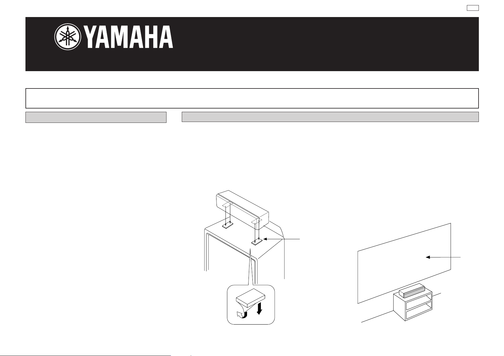
PLACING THE SPEAKER
Place the speaker on top of the TV or on the floor under
the TV or inside the TV rack so that it is stabilized.
When placing the speaker on top of the TV, to prevent the
speaker from falling down, put the provided velcro strips at
two points on both bottom of the speaker and top of the
TV.
Velcro
strip
TV set
& EFFECT SPEAKERS
Notes
● Do not place the speaker on top of the TV whose
area is smaller than the bottom area of the speaker.
If placed, the speaker may drop out causing an
injury to you.
● Though this speaker is a magnetic shielding type,
there may be some influence on a TV picture
depending on the type of TV or the placement of the
speaker. In such a case, place the speaker apart
from the TV so that there is no influence on TV picture.
Screen
Page 2
CONNECTION TO Y OUR AMPLIFIER
SPECIFICATIONS
BEFORE MAKING CONNECTIONS, MAKE SURE THAT
THE AMPLIFIER IS SWITCHED OFF.
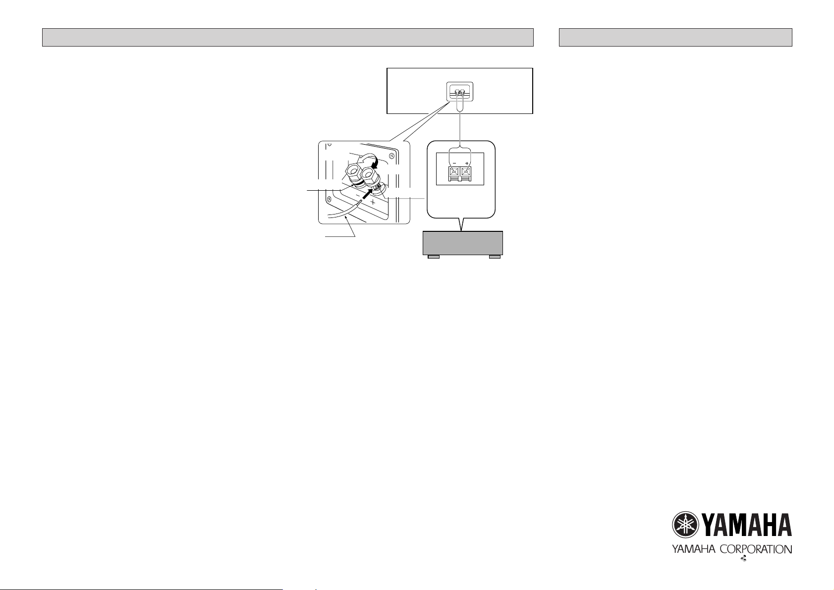
■ CONNECTIONS
● Connect the screw-type input terminals at the rear of the
speaker to the speaker output terminals of your amplifier
with the provided speaker cords.
● One side of the speaker cord is red and the other side is
black.Connect the (+) terminals on both the amplifier
and the speaker using this red side.Connect the (–) terminals on both components using the black side of the
cord.
● Be careful not to reverse the polarity (+, –). If connected
with reversed polarity, the sound will be unnatural and
lack bass.
Procedures:
➀ Loosen the terminal knob.
➁ Insert the bare speaker wire end properly into the ter-
minal hole. [Remove approx.10 mm (3/8”) insulation
from the speaker cord.]
➂ Tighten the knob.
➃ Test the secur ity of the connection by pulling lightly the
cord at the terminal.
NS-C55
Loosen
Tighten
Black (–)
Red (+)
Red
Note
Do not let the bare speaker wires touch each other as
this could damage the speaker or
the amplifier, or both of them.
Center speaker
output terminals
of the amplifier
Amplifier
Type..........................2-way 3-speaker acoustic-suspension
speaker system
Magnetic-shielding type
Speaker Unit....................................10 cm cone woofer x 2
2.2 cm dome tweeter
Input Terminal.....................................................Screw-type
Impedance .................................................................6 ohm
Frequency Response..................................70 Hz – 30 kHz
Nominal Input Power.....................................................60W
Maximum Input Power ................................................180W
Sensitivity (2.83V, 1m) ................................................91 dB
Crossover Frequency..................................................5 kHz
Dimensions (WxHxD) .......................465 x 135 x 173.5 mm
(18-5/16” x 5-5/16” x 6-7/8”)
Weight .................................................3.5 kg (7 lbs. 12 oz.)
Accessories......................................Speaker cord (4m) x 1
Velcro strip x 2
* Specifications subject to change without notice due to
product improvements.
* Care should be taken not to exceed the input power val-
ues noted above.
V415010
Page 3

NS-E55
Natural Sound Effect Speaker System
PRECAUTIONS
This model is designed to be used as an effect speaker system.
Read these precautions carefully before using your speakers.
● Any time you note distortion, reduce the volume control
on your amplifier to a lower setting.Never allow your
amplifier to be driven into “clipping”.Otherwise the
speakers may be damaged.
● When using an amplifier with a rated output power higher than the nominal input power of the speakers, care
should be taken never to exceed the speakers’maximum
input.
● Do not attempt to clean the speakers with chemical solvents as this might damage the finish.To clean, wipe
with a dry, soft cloth.
● To prevent the enclosure from warping or discoloring, do
not place the speakers where they will be exposed to
direct sunlight or excessive humidity.
● Do not place the speakers where they are liable to be
knocked over or struck by falling objects.Stable placement will also ensure better sound performance.
● Placing the speakers on the same shelf or rack as the
turntable can result in feedback.
● As these speakers contain strong magnets, avoid placing watches, magnetic tapes, etc.near them. Also, placing the speakers near a TV set may impair picture color.
If this happens, move the TV set away from the speakers.
● Secure placement or installation is the owner’s
responsibility.
YAMAHA shall not be liable for any accident caused
by improper placement or installation of the speakers.
SETTING UP THE SPEAKERS
■ Mounting the speakers on a wall
The speakers can be mounted on a wall by using the
holes provided on the speakers’back panels.
Pads
Holes
Make sure that the screws are caught by a narrow part of
the holes securely.
Put the screws into a wall according to the figure shown
below.
40 mm
Fasten screws into a firm wall or wall support as shown in
the figure below, and hang the holes on the protruding
screws.
Diam. 4 – 5 mm
Min.
12mm
2mm
Tapping screw
(Available at a
hardware store)
Wall or
wall support
WARNING
● Each speaker weights 2.2 kg (4 lbs.13 oz.). Do not
mount them on thin plywood or soft wall surface material, as the screws may come out of the flimsy surface,
causing the speakers to fall down and be damaged, or
result in personal injury.
● Do not fasten the speakers to wall with nails, adhesives,
or other unsound hardware. Long term use and vibrations may cause them to fall down.
● To avoid accidents resulting from tripping over loose
speaker cords, fix them to the wall.
Page 4

CONNECTION TO Y OUR AMPLIFIER
SPECIFICATIONS
BEFORE MAKING CONNECTIONS, MAKE SURE THAT
THE AMPLIFIER IS SWITCHED OFF.
■ CONNECTIONS
● Connect the screw-type input terminals at the rear of the
speakers to the speaker output terminals of your amplifier with the provided speaker cords.
● One side of the speaker cord has a gray line.Connect
the (+) terminals on both the amplifier and the speakers
using the side of the cord with the gray line.Connect the
(–) terminals on both components using the side without
a gray line.
● Connect one speaker to the left (marked L) terminals of
your amplifier, and another speaker to the right (marked
R) terminals, making sure not to reverse the polarity (+,
–). If one speaker is connected with reversed polarity,
the sound will be unnatural and lack bass.
Procedures:
➀ Loosen the terminal knob.
➁ Insert the bare speaker wire end properly into the ter-
minal hole. [Remove approx.10 mm (3/8”) insulation
from the speaker cord.]
➂ Tighten the knob.
➃ Test the secur ity of the connection by pulling lightly the
cord at the terminal.
Speaker (R)
Loosen
Black (–)
Gray line
Gray line Gray line
Speaker output
terminals of the
amplifier
Amplifier
Tighten
Red (+)
Speaker (L)
Type..........................2-way 2-speaker acoustic-suspension
speaker system
Speaker Unit..........................................10 cm cone woofer
2.2 cm dome tweeter
Input Terminal.....................................................Screw-type
Impedance .................................................................6 ohm
Frequency Response..................................80 Hz – 30 kHz
Nominal Input Power.....................................................50W
Maximum Input Power ................................................150W
Sensitivity (2.83V, 1m) ................................................90 dB
Crossover Frequency..................................................5 kHz
Dimensions (WxHxD) .......................150 x 265 x 156.3 mm
(5-7/8” x 10-7/16” x 6-3/16”)
Weight .................................................2.2 kg (4 lbs. 13 oz.)
Accessories ..................................Speaker cords (10m) x 2
* Specifications subject to change without notice due to
product improvements.
* Care should be taken not to exceed the input power val-
ues noted above.
Note
Do not let the bare speaker wires touch each other as
this could damage the speaker or
the amplifier, or both of them.
Page 5

documentation manual, user maintenance, brochure, user reference, pdf manual
This file has been downloaded from:
User Manual and User Guide for many equipments like mobile phones, photo cameras, monther board, monitors, software, tv, dvd, and othes..
Manual users, user manuals, user guide manual, owners manual, instruction manual, manual owner, manual owner's, manual guide,
manual operation, operating manual, user's manual, operating instructions, manual operators, manual operator, manual product,
 Loading...