

Yamaha Audio MY8-mLAN User Manual

Owner’s manual
mLAN Interface Card
MY8-mLAN
Bedienungsanleitung
Mode d’emploi
Manual de instrucciones
EnglishDeutschFrançaisEspañol
WARNING
CAUTION
Always follow the basic precautions listed
below to avoid the possibility of serious
injury or even death from electrical shock,
short-circuiting, damages, fire or other
hazards. These precautions include, but
are not limited to, the following:
• Do not attempt to disassemble or modify
the card. Do not apply excessive force to
card connectors or other card components. Mishandling of the card may lead to
shock, fire hazard, or equipment failure.
• Be sure to disconnect the power cable of
the main unit before installing this card (in
order to eliminate shock hazard).
Yamaha cannot be held responsible for data loss or equipment damage caused by
inappropriate handling or use.
Always follow the basic precautions listed
below to avoid the possibility of physical
injury to you or others, or damage to the
instrument or other property. These
precautions include, but are not limited
to, the following:
• The card is sensitive to static electricity.
Before handling the card, you should
briefly touch the metal casing of the main
unit with your bare hand to discharge any
static charge from your body. Failure to do
so may damage the card.
• Do not touch the metallic leads (pins) of the
circuit board when handling the card. The
pins are sharp and may cause hand cuts.
2
Introduction
Thank you for purchasing the Yamaha MY8-mLAN. The MY8-mLAN is an interface card that
provides mLAN interfacing. mLAN is a digital network designed for music and based on the IEEE
1394 high performance serial bus. mLAN makes it easy to construct sophisticated networks for
audio and MIDI signals that can be re-configured without changing the physical cabling (as was
necessary with previous systems).
The MY8-mLAN adds two mLAN connectors to the Yamaha AW4416 or AW2816 professional
audio workstations, or to the Yamaha 01V digital mixing console etc. (Consult your Yamaha
dealer for details of other applicable Yamaha equipment.)
Package Contents
• MY8-mLAN
• mLAN Tools (CD-ROM)
• IEEE 1394 cable (4.5 m)
• Owner’s manual (this document)
• mLAN guidebook
• mLAN Tools installation guide
English
About the included CD-ROM
The included CD-ROM contains software that is useful when used in conjunction with the
MY8-mLAN. This software includes “mLAN Patchbay” which lets you make settings on
your computer to specify the routing of audio/MIDI signals between mLAN devices connected to the MY8-mLAN. For details refer to the separate “mLAN Tools Installation
Guide.”
Yamaha cannot be held responsible for damage caused by improper use or
modifications to the instrument, or data that is lost or destroyed.
The illustrations shown in this Owner’s Manual are for instructional purposes only, and may
appear somewhat different from those on your device.
The company names and product names in this Owner’s Manual are the trademarks or registered
trademarks of their respective companies.
3
Table of Contents
Introduction ................................................................................... 3
Package Contents........................................................................... 3
How to install the MY8-mLAN ....................................................... 5
Names and Functions..................................................................... 6
English
DIP switch (SW1) settings.............................................................. 7
Connections.................................................................................. 10
About mLAN connections ............................................................ 11
Internal Configuration of the MY8-mLAN................................... 12
LED Messages ............................................................................... 13
Specifications................................................................................ 14
4
How to install the MY8-mLAN
1. Set the MY8-mLAN’s DIP switch (SW1) according to your application. For details refer to page
7.
NOTE
It is not possible to change the setting of the DIP switch (SW1) after the MY8-mLAN is
installed. You must set the DIP switch before installation. If you want to change the settings,
you must turn off the host device, remove the MY8-mLAN, and then change the settings.
2. Install the MY8-mLAN into your device. For details refer to the operation manual for your
device.
WARNING
You must turn off the power of your device before you begin installing the MY8-mLAN.
3. Connect the device into which the MY8-mLAN was installed to your other mLAN (IEEE 1394)
devices or IEEE 1394-compatible computer. For details refer to page 10.
4. Make mLAN connection settings. For details refer to page 12.
MY8-mLAN Installation Precautions
• Before beginning installation, switch off the power to the main unit and any connected periph-
erals, and unplug them from the power outlet. Then remove all cables connecting the main
unit to other devices. (Leaving the power cord connected while working can result in electric
shock. Leaving other cables connected can interfere with the installation procedure.)
• It is recommended that you wear gloves to protect your hands from sharp or pointed projec-
tions on the equipment.
• Board components may be damaged by electrostatic discharge. Be sure to drain any electro-
static charge from body and clothes before starting work. Keep hands clear of board components, board circuitry, and metallic leads while carrying out the installation.
• Handle the plug-in boards with care. Dropping or subjecting the card to any kind of shock may
cause damage or result in a malfunction.
• Do not touch the exposed metal parts in the circuit board. Touching these parts may result in a
faulty contact.
• Take care to avoid dropping screws into the main unit. If a screw does fall in, be sure to remove
it before you reassemble and power up the unit. Starting the unit with a loose screw inside may
lead to improper operation or to equipment failure. (If you are unable to retrieve a dropped
screw, consult your Yamaha dealer for advice.)
English
5
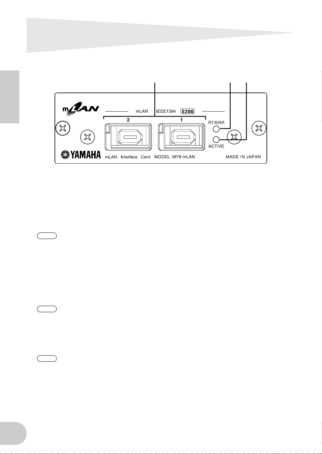
Names and Functions
English
A mLAN (IEEE1394) jacks
These jacks are used to connect mLAN devices or IEEE1394-compatible devices via IEEE1394 standard (6-pin) cables. Each jack has an LED in the upper left corner to indicate the following statuses.
green : The MY8-mLAN or connected device is a “leaf” node.
off : Not connected.
red : When there is a possibility that the sound will be interrupted.
NOTE
B RT/ERR LED
This LED indicates the following statuses.
green : The MY8-mLAN is a “root” node.
orange : An IEEE 1394 bus-related error has occurred.
red : Another type of error has occurred.
off : Normal operating condition other than the above.
If you disconnect the cable from the jack or turn off the power of the device when the LED is lit
red, the sound on the bus (system) will be momentarily interrupted.
1
2
3
C ACTIVE LED
6
NOTE
This LED indicates the following statuses.
blue : The relay function between mLAN (IEEE 1394) jacks is active.
off : The relay function between mLAN (IEEE 1394) jacks is inactive.
NOTE
Refer to “LED Messages” on page 13 for information on the error indication.
Since the MY8-mLAN will stop functioning as a bus relay when the power of the main unit is
turned off, this LED will also correspond to the power on (lit blue) or off (dark) status.
 Loading...