

Yamaha Audio MT2X User Manual

®
YAMAHA
AUTHORIZED
PRODUCT MANUAL
Multitrack Cassette Recorder
Y A MA HA
Multit r ack Cassett e Recor der
Operating Manual

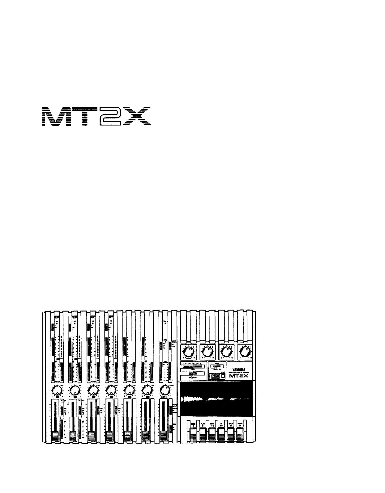
Congratulations on your choice of the Yamaha MT2X Multitrack Cassette
Recorder. The Yamaha MT2X Multitrack Cassette Recorder is a complete
multitrack recording package which elegantly integrates a high-performance
six-channel mixer and dual-speed 4-track cassette recorder. It is fully compatible with advanced MIDI tape synchronization applications, and accepts
an optional plug-in YMC2 MIDI Converter that makes MIDI timing signals
from any appropriate MIDI device usable for synchronization With a full
complement of carefully planned features and functions, the MT2X is a
musical instrument in its own right. It can vastly expand your creative
scope.
To take full advantage of the outstanding features and performance
capabilities of the MT2X, we urge to read this owner’s manual thoroughly.
CONTENTS
BEFORE OPERATION
PLEASE NOTE THE FOLLOWING PRECAUTIONS
THE DIFFERENCE BETWEEN TRACKS AND CHANNELS
WHAT IS A MULTITRACK CASSETTE RECORDER? .................. 3
THE CONTROLS AND THEIR FUNCTIONS
MIXER SECTION ................................................................... 4
RECORDER SECTION
METER AND MONITOR SECTION
CONNECTOR SECTION
CONNECTION EXAMPLE
ABOUT CASSETTE TAPES
MULTITRACK RECORDING TECHNIQUES
ONE EXAMPLE OF A MULTITRACK RECORDING PROCESS
BEFORE RECORDING
MULTITRACK RECORDING
USING CHANNELS 5 AND 6 ..................................................
SYNC-RECORDING
FOR MAXIMUM
BLOCK DIAGRAM
GENERAL SPECIFICATIONS
INTRODUCTION TO THE ACCESSORIES
SERVICE
..................................................................................
................................................................. 2
...................... 2
............ 3
.................................... 4
............................................................
...........................................
..........................................................
............................................................
.........................................................
....................................
.......
.............................................................
....................................................
.................................................................... 34
PERFORMANCE OF YOUR
MT2X ........................ 35
.....................................................................
.......................................................
......................................
8
10
12
14
15
16
16
16
17
33
36
37
38
39
1

BEFORE OPERATION
n
PLEASE NOTE THE FOLLOWING PRECAUTIONS:
ABOUT CASSETTE TAPE
This unit is designed to be used only with Chromeposition tape, and will not work properly with Ferri-
chrome tape formulations. CrO
EQ: 70µs) should be used. Also, the use of C-120
tapes is not recommended because they exhibit
poorer performance, and can be the cause of equipment failure.
ABOUT dbx
In order to get proper sound reproduction, set the dbx
switch ON when playing back tapes recorded with
dbx on, and keep it OFF when playing back tapes
recorded without dbx.
*dbx and the dbx mark are trademarks of dbx in-
corporated.
*The dbx system has been manufactured under
license of dbx Incorporated.
CHECK YOUR AC POWER SUPPLY
Make sure that your local AC mains voltage matches
the voltage specified on the bottom panel of the
MT2X — check this BEFORE plugging in and turning
on your MT2X! For General models equipped with a
voltage selector, make sure the voltage selector is set
to match your local line voltage.
The rated supply voltage for U.S. and Canadian
models is 120 VAC. The General model is rated for
use with 110/120/220/240 VAC supplies (the bottompanel voltage selector is factory preset to
220 volts).
2 tape (Bias: HIGH;
PRECAUTION AGAINST LIGHTNING
In the event of lightning or electrical storms, unplug
the AC power cord as soon as possible to avoid potential damage.
DO NOT OPEN THE CABINET
To avoid electrical shock or damage to the unit, do
not open the cabinet and tamper with the parts or
circuits inside.
CONNECTING OTHER EQUIPMENT
Make sure the power switch is OFF and the input
fader is all the way down when connecting other
equipment.
MOVING THE UNIT
To prevent shorts or breakage, make sure all connection cords have been removed from the unit before
moving it.
CLEANING THE CABINET
Do not clean the unit with benzene or other powerful solvents, and avoid the use of aerosol insecticides
near the unit. Clean the unit only with a soft, dry
cloth.
This equipment generates and uses radio frequency energy and if not installed and used properly, that
is, in strict accordance with the manufacturer’s
instructions, may cause interference to radio and
television reception. It has been type tested and
found to comply with the limits for a Class B computing device in accordance with the specifications
in Subpart J of Part 15 of FCC Rules, which are
designed to provide reasonable protection against
such interference in a residential installation. However, there is no guarantee that interference will not
occur in a particular installation. If this equipment
does cause interference to radio or television reception, which can be determined by turning the equipment off and on, the user is encouraged to try to
correct the interference by one or more of the follow-
ing measures:
FCC CERTIFICATION (USA)
Reorient the receiving antenna.
Relocate the computer with respect to the receiver.
Move the computer away from the receiver.
Plug the computer into a different outlet so that
computer and receiver are on different branch circuits.
If necessary, the user should consult the dealer
or an experienced radio/television technician for additional suggestions. The user may find the following booklet prepared by the Federal Communications
Commission helpful:
“How to identify and Resolve Radio-TV interference problems”.
This booklet is available from the U.S. Government
Printing Office, Washington, DC 20402, Stock No.
004-000-00345-4.
2
n
THE DIFFERENCE BETWEEN TRACKS AND CHANNELS
The words “track” and “channel” are often confused. In order to properly operate this unit, it is necessary to understand the meanings of these terms.
TRACK:
The “band” on the tape itself where a certain signal is
recorded. The tape inside a cassette has four different
tracks, enabling the recording of four distinct signals.
For conventional recordings, there are two tracks (stereo
CHANNEL:
The route of a signal input or output. In the input side,
this unit has six INPUT channels and two AUX channels.
The output side consists of one stereo channel (made
up of two mono channels) and an AUX channel.
left and right) on each side of the tape.
n
WHAT IS A MULTITRACK CASSETTE RECORDER?
The difference between the MT2X multitrack cassette recorder and a conventional stereo cassette deck is shown
below.
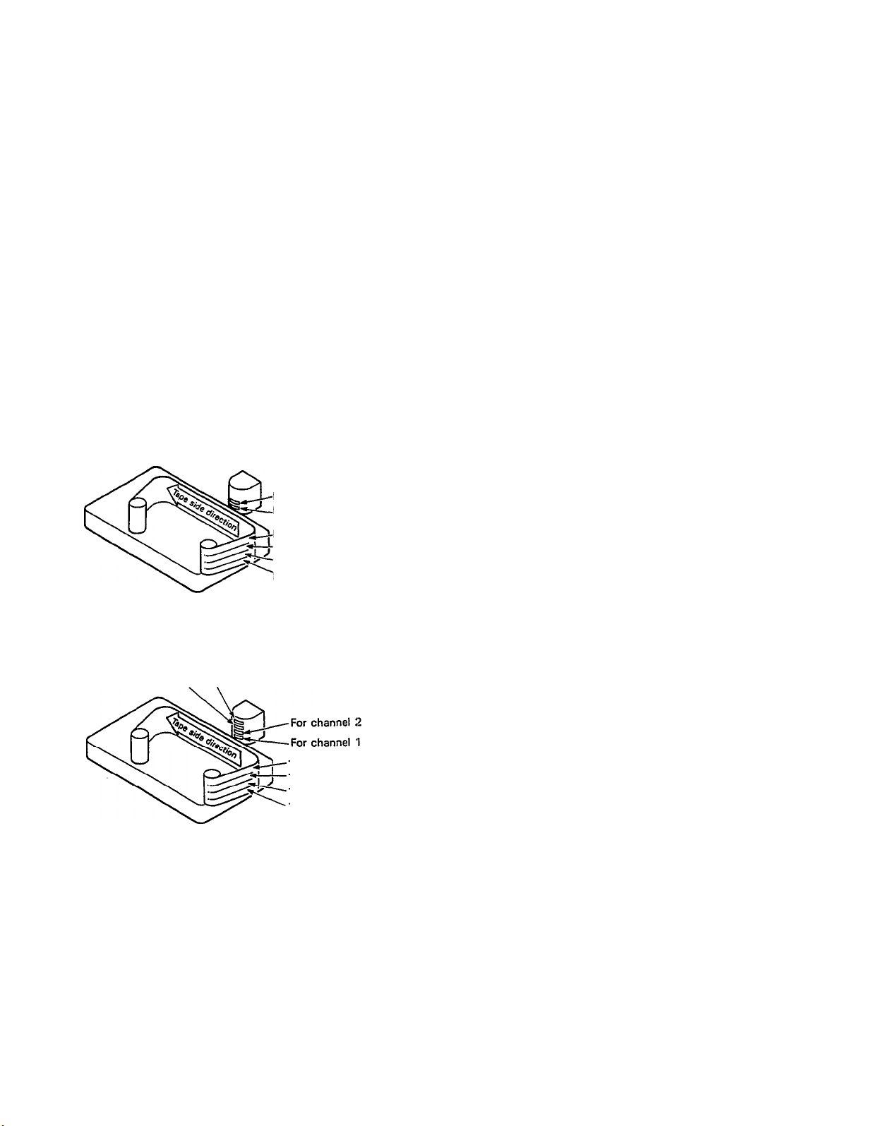
CONVENTIONAL STEREO CASSETTE DECK
The diagram shows how a conventional stereo cassette
deck records and plays back music. The four tracks on
a cassette tape represent the left and right (for stereo)
For right channel track
For left channel track
For left channel track on the B side
For right channel track on the B side
For right channel track on the A side
For left channel track on the A side
sound for each side of the tape. The MT2X uses these
four tracks for single-direction recording and playback
on only one side of a cassette tape.
Conventional stereo cassette recorders always record
and play back in the same mode, with the tape side
(direction) determining which two tracks will be used.
These recorders do not allow separate selection of tracks
for recording and playback.
Multitrack recorders, however, allow you to record or
MT2X MULTITRACK CASSETTE RECORDER
playback tracks separately as you choose. This enables
a degree of recording and playback freedom not possible
For channel 3
For channel 4
with conventional cassette recorders.
Track for channel 4 (track 4)
Track for channel 3 (track 3)
Track for channel 2 (track 2)
Track for channel 1 (track 1)
3
THE CONTROLS AND THEIR FUNCTIONS
This section explains the names and functions of all the knobs, sliders, and switches for the mixer, recorder, meter/
monitor, and connector sections. Familiarize yourself with them in order to take full advantage of the MT2X’s versatile functions.
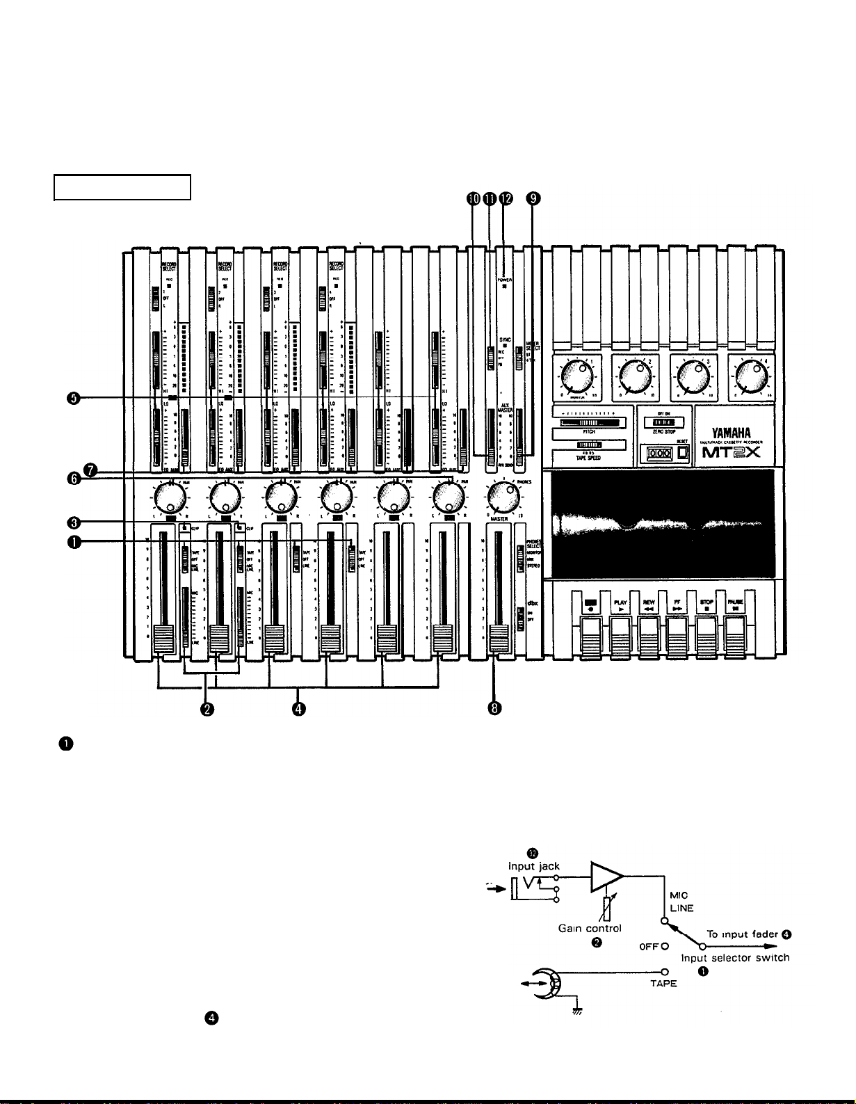
MIXER SECTION
INPUT SELECTOR SWITCHES
These three-position switches are provided on input
channels 1 through 4. Position them according to the
operation to be performed. Note that input channels 5
and 6 only accept line input.
MIC/LINE: Only input channels 1 and 2 accept
microphone input. This position on the channel 3 and 4 inputs is simply marked “LINE”.
Set this switch to the proper position when
the output of a microphone, keyboard instrument, or electric guitar is connected to the
corresponding input jack on the front panel.
OFF:
Be sure to set the switch to this position
when the channel is not being used, or when
you don’t want to playback material already
recorded on the track. Although sliding the
input fader to the “O” position will stop
the signal, it’s a good idea to also set the
switch to OFF.
TAPE:
Microphone or
instrument
to channel
1 or 2
Sounds already
recorded
Set the switch to this position to playback
material which has already been recorded on
this channel. Channels 1–4 correspond to
tracks 1–4 on the tape.
4
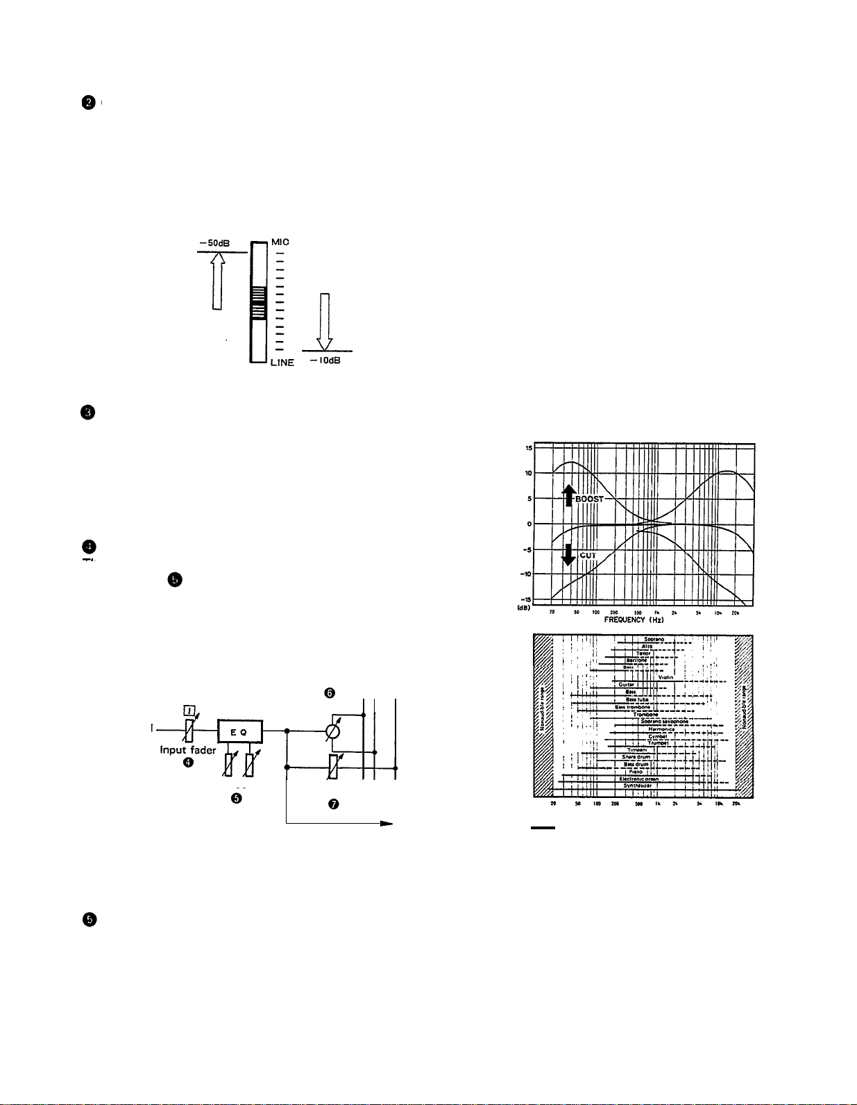
GAIN CONTROLS
These controls adjust the input level of the channel
to match the output level of a microphone or instru-
ment connected to input jack of channel 1 or 2.
Control from
-10dB to -50dB is possible. Adjust
the output level of the microphone or instrument as
outlined in its instruction booklet.
Low output source,
such as a microphone
High output source,
such as an
electronic
keyboard
you to get the type of sound you desire, and allow you
to bring the sound “forward”, “clean up” unclear sounds,
and “push down” sounds at annoying frequencies.
In order to properly use these equalizers, it’s important
to understand the frequency response characteristics
of various musical instruments. This is particularly true
when trying to “change” the sound of a certain in-
strument, because you should know that instrument’s
harmonic sound components as well. For example, the
normal frequency range of a bass drum is between 50Hz
and 150Hz. To bring out this sound so you can feel it
better, the LO (low) control (which centers on the 100Hz
frequency band) can be moved up a little. But the harmonic sound components are around I0KHz, so the HI
(high) control should also be moved up a little to achieve
the proper sound profile of the bass drum.
CLIP INDICATOR
These LED indicators are provided on channels 1 and 2.
If a CLIP LED lights, the input level to that channel is
too high and is causing clipping distortion. The situation
must be remedied by reducing the setting of the corres-
ponding GAIN control, or by reducing the output level
of the source.
INPUT FADERS
These controls adjust the volume of the signal input, and
send it to the equalizer. Each control is used for setting the sound level of its channel when mixing it with
the signals of other channels. Position “7” on the scale
is considered ideal for the lowest noise and distortion
characteristics.
L R AUX
Pan pot
Input signal
Equalizer controls AUX control
SOUND CHARACTERISTICS OF THE EQUALIZER AND
VARIOUS MUSICAL INSTRUMENTS
Be sure to set the control to “0” for channels not being
used.
EQUALIZER CONTROLS
These controls are used to adjust the tonal character-
istics of the input signal, or the channel output during
playback of previously recorded material. The LO (low)
controls adjust the frequencies centering around 100Hz,
while the HI (high) controls adjust the frequencies center-
ing around 10KHz, with a 10dB boost or cut range for
both controls. Use of these equalizer controls will help
5
FREQUENCY (Hz)
Normal frequency ----- Harmonic sound
components
If accurate and comprehensive sound equalization is
required, connect a graphic equalizer or a parameteric
equalizer between the sound source and the input jack.
When recording material that you intend to “ping-pong”
(see “Ping-ponging” on page 25) later, give the input
somewhat of a high boost with the Hi control to help
preserve the high frequency response when the track is
re-recorded. This technique is known as “pre-emphasis,”
and is commonly used in professional recording.
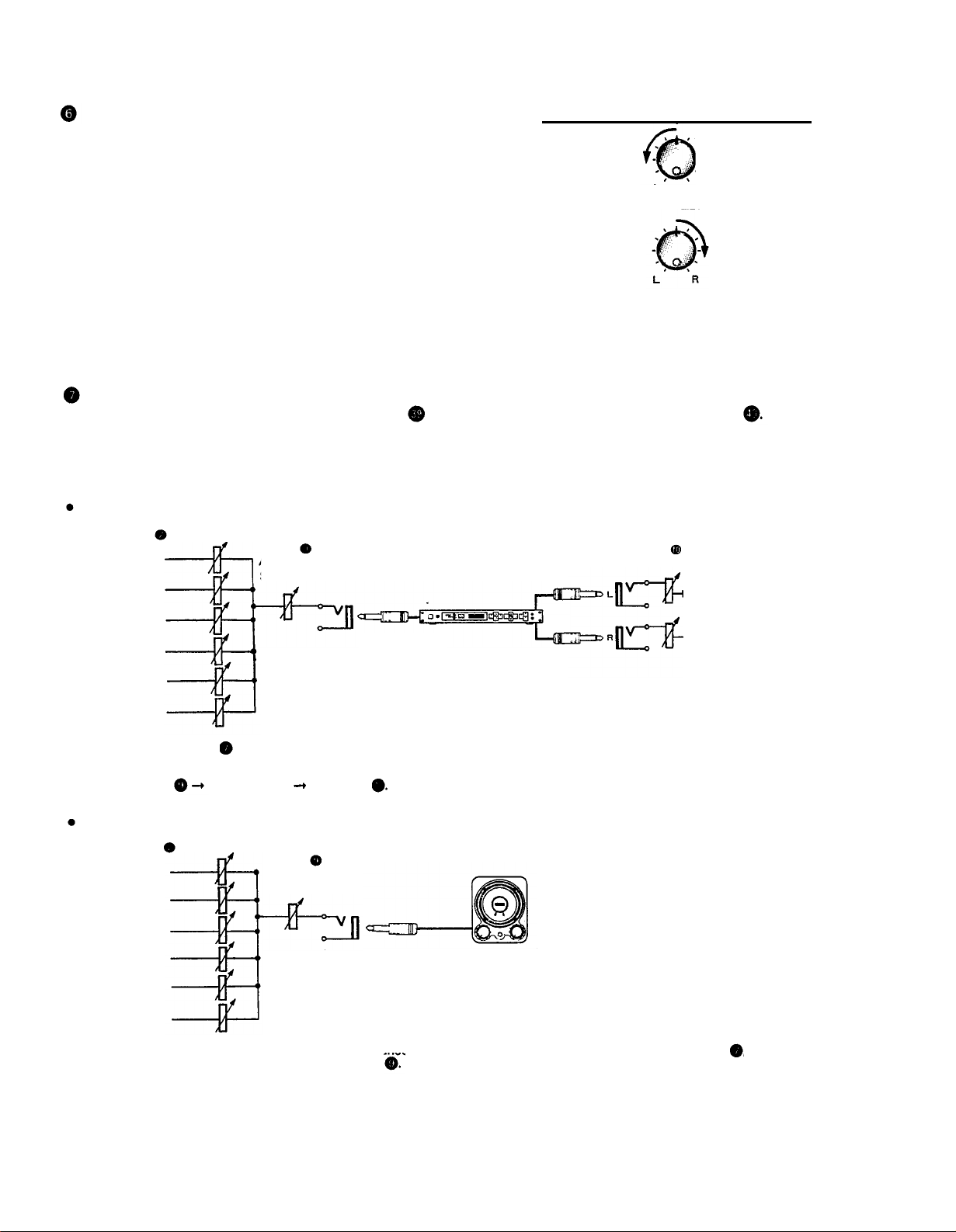
PAN (PAN POT) CONTROLS
After volume level and equalizing, the input signal is sent
to these controls. During mixdown (see “Mixdown” on
page 31, each control helps determine the acoustic
“position” of the signal in regards to the stereo field.
Turning the control all the way to the left puts the signal
all the way over to the left side of the stereo sound field;
turning the control to the right sends the signal towards
the right. At dead center, the signal comes out equally
from the left and right channels.
L
I
All the way to the left,
the signal comes out
from the left channel.
L
Center
PAN
R
PAN
All the way to the
right, the signal comes
out from the right
channel.
R
I
These controls are also useful in ping-ponging (see “Pingponging” on page 25).
AUX CONTROLS
The MT2X is equipped with an AUX SEND jack
and two (left and right) AUX RETURN jacks
When special
effects are desired on a certain channel, reverb or delay effects can be connected between these jacks to provide
only the desired effect to the desired channel. Amplified monitor speakers can also be connected to the AUX SEND
jack. Each AUX control adjusts the sources connected to the AUX SEND jack in the following manner.
CONNECTING AN EFFECTOR
AUX controls
Channel 1 signal
Channel 2 signal
Channel 3 signal
Channel 4 signal
Channel 5 signal
Channel 6 signal
Raise the AUX control of the channel which requires effects. At the same time, make sure that the AUX controls for the other channels
are adjusted for proper balance. The effected signal, with all the channel signals mixed in, flows in the following manner: AUX MASTER
SEND control effects device AUX RTN . At the end, the sounds are mixed by the stereo mix buss.
CONNECTING MONITOR SPEAKERS
AUX MASTER
SEND control
Effects device
(digital reverb, digital delay, etc.)
AUX RTN control
To the left & right
stereo mix busses
AUX control
Channel 1 signal
Channel 2 signal
AUX MASTER
SEND control
Channel 3 signal
Channel 4 signal
Channel 5 signal
Channel 6 signal
Performers or sound mixers can control the level balance of the four channels (instruments) with the AUX controls
level adjusted by the AUX MASTER SEND control
Amplified monitor
speakers
, with the total output
6
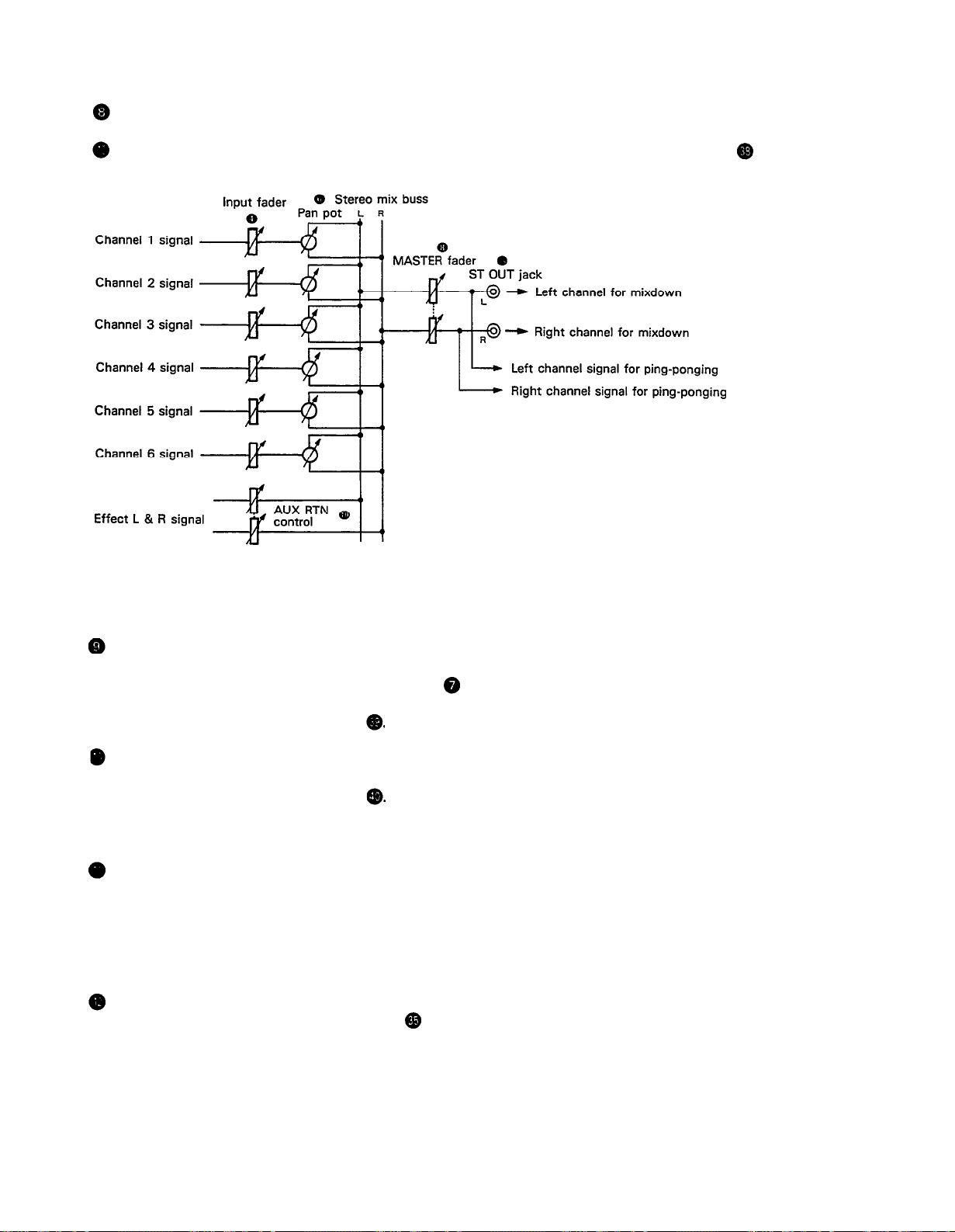
MASTER FADER
This controls the level of all the input faders, as well as the final level of the effected signal of the AUX RTN control
and the sound mixed through the stereo mix buss. The output level of the ST OUT jack (the recording level
at mixdown) and the recording level during ping-ponging are also adjusted with this control.
Set the control input faders at “7” for best results.
AUX MASTER SEND CONTROL
This control adjusts the level of the effect-mixed signals
from each channel (adjusted by each AUX control )
as well as the AUX signal for monitoring use. The final
output is through the AUX SEND jack
AUX RETURN CONTROL
This control adjusts the input level of effects or sub-
mixers connected to the AUX RTN jack . The level of
the effect in relation to the “dry” sound can be set with
this control.
SYNC SWITCH
Normally left in the “OFF” position, this switch should
be set to REC or PB if this unit is to be used for synchronized operation with MIDI products like synthesizers
and rhythm machines. Synchro operation is explained in
the section on Sync-Recording on page 34.
POWER INDICATOR
This indicator lights when the power switch on the
rear panel is turned on.
7
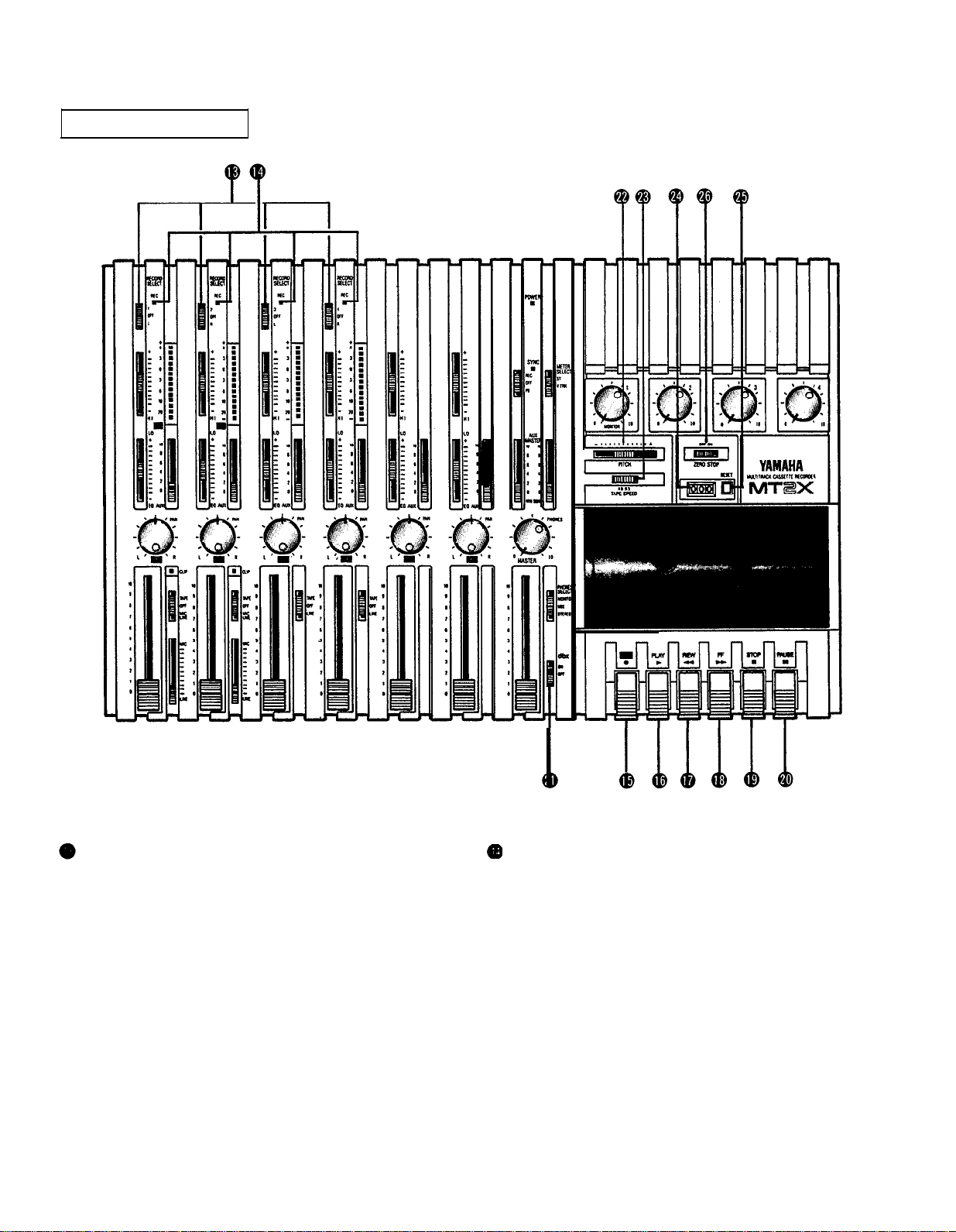
RECORDER SECTION
RECORD SELECT SWITCHES
These switches are used to choose the signal to be
recorded. When the track is not to be recording, set the
corresponding switch to the OFF position. Switch ON
only those switches corresponding to the tracks which
are to record. The panel indications for “L" and “R” cor-
respond to the stereo left and right signals, whereas “1”,
“2”, “3”, and “4” correspond to the signal from the 1,
2, 3, and 4 input channels. Those signals are recorded
on their respective track when the switches are in
position.
NOTE:
Tracks 1 and 3 cannot be recorded from the right
stereo signal, and tracks 2 and 4 cannot be
recorded from the left stereo signal.
REC INDICATORS
Each track on the MT2X has its own REC indicator LED.
When the RECORD SELECT switches are used to set one
or more of the tracks to the REC standby mode (that is,
the selected tracks are ready to record but the cassette
transport is not yet running in the REC mode), the cor-
responding REC INDICATOR(s) will flash. When recording is actually begun, the REC INDICATORS for the
selected tracks will light continuously.
8

REC SWITCH
When this switch is pressed, the PLAY switch also
moves, and the unit goes into the recording mode.
However, if the RECORD SELECT switches for all tracks
1-4 are switched OFF, nothing will be recorded.
NOTE: When the REC switch is pressed down, noise
occurs which is recorded on the tape. In order
to prevent this, we recommended the use of the
PAUSE switch . Press the PAUSE switch first,
then press the REC switch. To start recording,
press the PAUSE switch again to shift out of the
REC pause mode
and into the recording mode.
PITCH CONTROL
During recording or playback, this control can be used
to vary the tape running speed from +10% to -10%.
The pitch of voices or musical instruments also varies
in proportion to tape speed.
Under normal conditions, the control should be in the
center position. When overdubbing (playing back a
recorded passage while recording new material on a dif-
ferent track) the pitch of the previously recorded material
can be altered to match the new material if necessary.
This feature can also be used to obtain certain special
effects during recording.
PLAY SWITCH
Press this switch for playback. However, if the input
selector switch of a track is not in the TAPE position,
the sound will not be heard on the stereo buss.
REW SWITCH (REWIND)
Use this switch to rewind the tape. Pressing it when
the MT2X is in the PLAY mode enables you to hear the
sound of the tape while it rewinds. This feature is useful for finding the beginning of a song or other recorded
material.
FF SWITCH (FAST FORWARD)
Use this switch to quickly advance the tape forward.
Pressing it when the MT2X is in the PLAY mode enables
you to hear the sound of the tape while it is moved forward. This feature is useful for cueing up the start of
a subsequent song or other recorded material on the
tape.
STOP SWITCH
Press this to stop tape.
PAUSE SWITCH
Press this switch to momentarily stop playback or
recording in progress. Press it again to restart.
TAPE SPEED SWITCH
This switch selects either LO (4.8 cm/s) or HI (9.5
cm/sec) cassette tape speed. The low-speed setting cor-
responds to standard cassette tape speed, offering max-
imum recording time. The HI setting causes the tape
to run at twice the standard tape speed, reducing avail-
able recording time but significantly improving sound
quality.
TAPE COUNTER
This displays the amount of tape run.
RESET SWITCH
Press this switch to reset the tape counter to “000”.
Pressing this switch at the start of recording, or at the
beginning of a song, makes it easy to cue up the selec-
tion from the start.
ZERO STOP SWITCH
If this switch is set “ON” during rewinding, the tape
will stop when the tape counter reaches “999”. During
multitrack recording, this feature is convenient for
repeated playback or recording operations after rewind.
dbx SWITCH
Ordinary cassette tapes don’t have sufficient dynamic
range (the level difference between the softest sounds
and the loudest peaks) to adequately record highly
dynamic music. If the dbx switch is put “ON” during
recording, highly dynamic music signals can be adequately handled, while the hiss noise inherent to cassette
tapes is kept down below the range of human hearing.
If the dbx switch is kept “ON” during recording, it must
also be kept “ON” during playback.
9
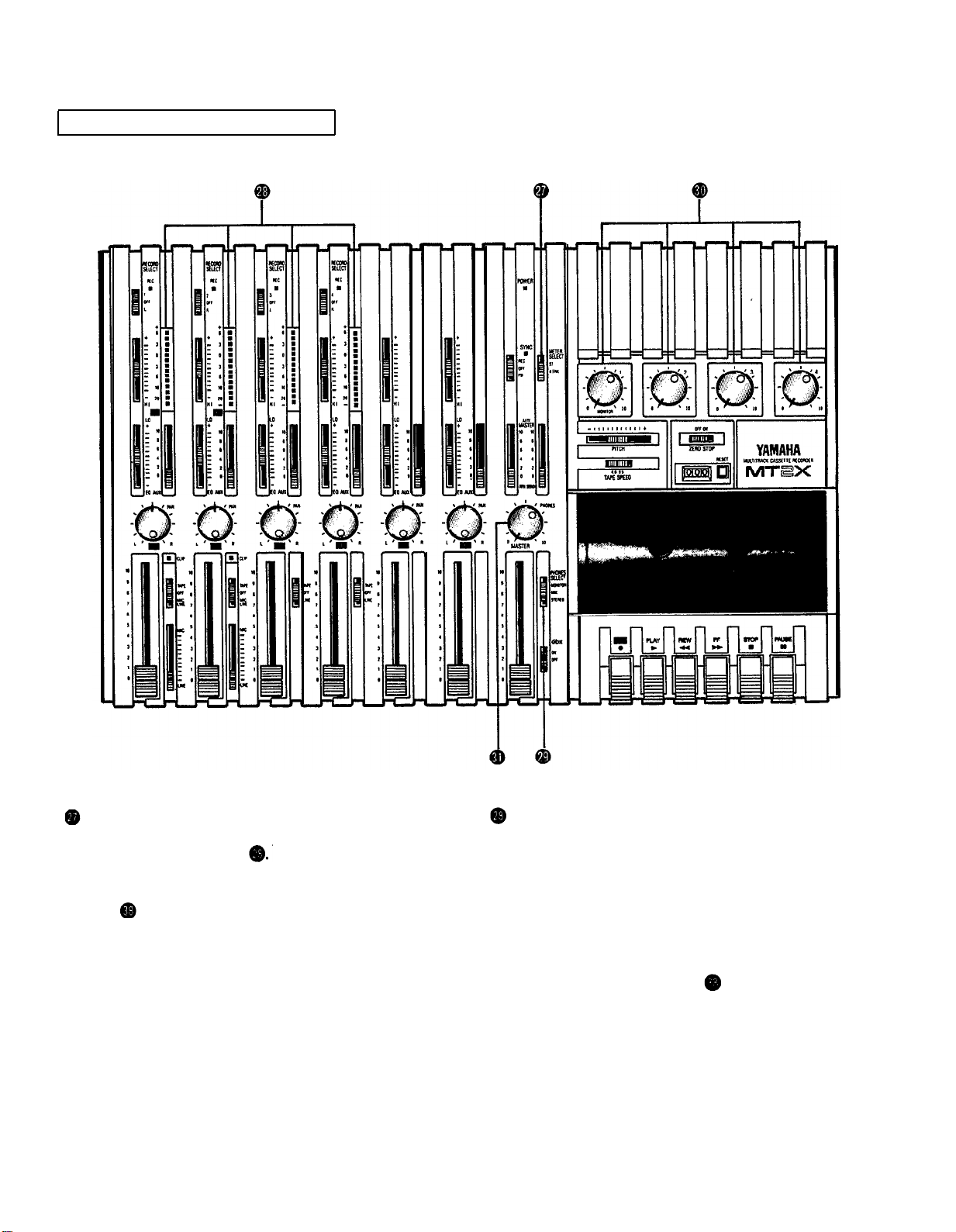
METER AND MONITOR SECTION
METER SELECT SWITCH
This switch is used to select the signal to be monitored
by the Peak Level Meters
Stereo Position:
The level of the signal output through the ST OUT
jacks is indicated. The meter on the far left shows
the level of the Left channel of the stereo signal, while
the second meter from the left shows the level of the
Right channel. Setting to this position during pingponging or mixdown operations enables easy reading
of the recording level.
4 TRK Position:
Set the switch in this position to display the level of
each track. Starting from the far left, each meter corresponds to tracks 1–-4. During playback, the playback level is displayed; during recording, the recording level is displayed. Setting the switch to this position during overdubbing enables easy reading of the
recording level.
PEAK LEVEL METERS
There are 14 LED indicators in each meter which show
a range from - 20dB to +6dB. During recording, setting
levels high (but below the point where the recording
becomes distorted) will ensure the greatest dynamic
range with the lowest possible noise. An ideal point is
when the LED indicators for 0dB and above flash occasionally.
During stereo signal level indication, the actual specified
output from the ST OUT jacks is - 10dB (into a 50K
ohm load) when the LED indicators start to flash at 0dB.
10
PHONES SELECT SWITCH
You can plug a set of headphones into the PHONES jack on the front panel to monitor the sound. The PHONES
SELECT Switch is used to select the signal to be monitored. Control the volume level with the PHONES volume
control .
STEREO Position:
Put the switch in this position to monitor the signal output through the ST OUT jacks .
The Left and Right chan-
nels of the stereo signal will be heard through the headphones.
When set to this position during ping-ponging or mixdown operations, the mixed signal of all the instruments can
be monitored.
MONITOR Position:
This position is for monitoring the signal of each track. You can freely monitor while mixing the sound of each
track during recording or playback. Using the MONITOR LEVEL Controls
set the desired level for each track.
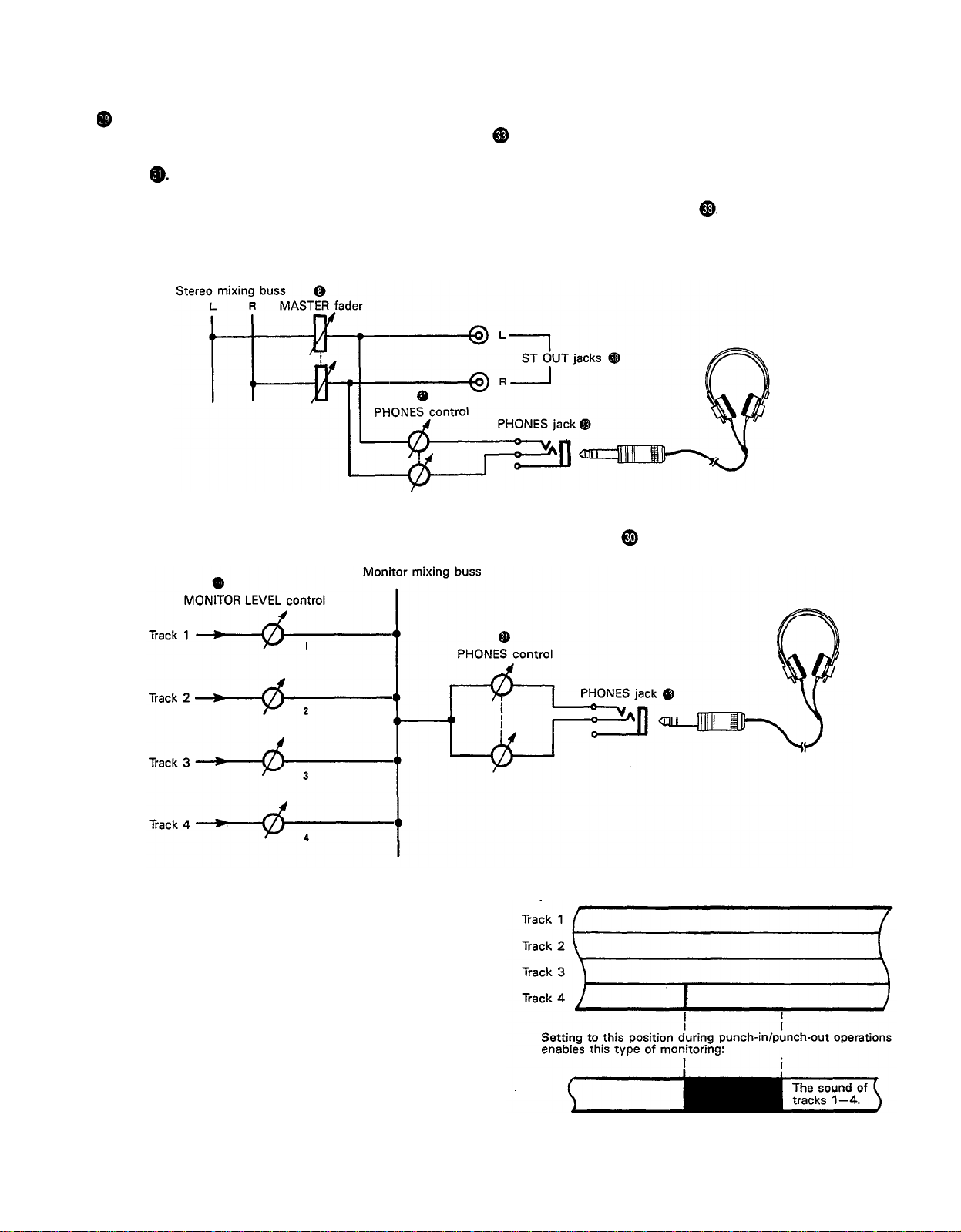
MIX Position:
This position allows you to simultaneously monitor
both the sound heard in the STEREO position and the
sound heard in the MONITOR position. Setting to this
position during punch-in/punch-out operations will
enable the type of monitoring shown below. (Refer to
“Punch-in/Punch-out” on page 27).
11
For
way:
example,
when adding in instruments or vocals in the following
The sound of
tracks 1-4 plus the
plus the sound
of the material
to be added.
For retake
Tracks 1-3
sound of the
material
added.
 Loading...