

Page 1

®
YAMAHA
AUTHORIZED
PRODUCT MANUAL
Page 2
YAMAHA
MULTITRACK CASSETTE RECORDER
OPERATING MANUAL
Page 3

Congratulations on your choice of the New Yamaha MT1X Multitrack
Cassette Recorder. The MT1X is a compact multitrack recorder with a
recording mixer, and is equipped with numerous versatile functions. Using
conventional cassette tapes, the MT1X makes it easy for you to produce
high quality multitrack recordings. Besides use as a multitrack recorder,
the MT1X can also be used as a PA mixer for small performances, as well
as for editing soundtracks for videos.
To take full advantage of the outstanding array of features, and for years
of trouble-free operation, we urge you to thoroughly read this operating
manual. After reading, keep it in a handy place for reference.
C O NTENTS
BEFORE OPERATION
PLEASE NOTE THE FOLLOWING PRECAUTIONS
THE DIFFERENCE BETWEEN TRACKS AND CHANNELS
WHAT IS A MULTITRACK CASSETTE RECORDER?
THE CONTROLS AND THEIR FUNCTIONS
MIXER SECTlON
RECORDER SECTION
METER AND MONITOR SECTION
CONNECTOR SECTION
CONNECTION EXAMPLE
ABOUT CASSETTE TAPES
ATTACHING THE STRAP
WHEN USING THE BATTERY PACK
MULTITRACK
RECORDING TECHNIQUES
ONE EXAMPLE OF A MULTITRACK RECORDING PROCESS . . . . . . .
BEFORE RECORDING
MULTITRACK RECORDING
SYNC-RECORDING
EDITING VIDEO SOUNDTRACKS
MAINTENANCE
BLOCK DIAGRAM .............................................
SPECIFICATIONS35...................................................
INTRODUCTION TO THE ACCESSORIES
SERVICE
. . . . . . . . . . . . . . . . . . . . . . . . . . . . . . . . . . . . . . . . . .
. . . . . . . . . . . . . . . . . . . . . . . . . .............
.. . . . . . . . . . . 2
........ 3
. . . . . . . 3
. . . . . . . . . . . . . . . . . . . . 4
. . . . . . . . . . . . . . . . . . . . . . . . . . . . 4
.............................
.......................
.. . . . . . . . . . . . . . . . . . . . . . . .
. . . . . . . . . . . . . . . . . . . . . . . . . . . .....
. . . . . . . . . . . . . . . . . . . . . . . . . .
............................
. . . . . . . . . . . . . . . . . . . . .
. . . . . . . . . . . . . . . . . . . . . . .
. . . . . . . . . . . . . . . . . . . . . . . . . . . . . . . .
.............................. 17
. . . . . . . . . . . . . . . . . . . . . . . . . . . . . . . . . . . . . . .
. . . . . . . . . . . . . . . . . . . . . . . . 34
. . . . . . . . . . . . . . . . . . . . . . . . . . . . . . . . . . .
........................
2
7
9
11
13
14
15
15
16
16
16
33
34
36
37
38
1
Page 4

BEFORE OPERATION
PLEA SE NO TE THE FO LLO WING PREC A UTIO NS:
• ABOUT CASSETTE TAPE
This unit is designed to be used only with Chromeposition tape, and will not work properly with Ferrichrome tape formulations. CrO tape (Bias: HIGH; EQ:
70µs) should be used. Also, the use of C-120 tapes
is not recommended because they exhibit poorer performance, and can be the cause of equipment failure.
• ABOUT dbx
In order to get proper sound reproduction, set the dbx
switch ON when playing back tapes recorded with
dbx on, and keep it OFF when playing back tapes
recorded without dbx.
*dbx and the dbx mark are trademarks of dbx in-
corporated.
*The dbx system has been manufactured under
license of dbx Incorporated.
• USING THE AC ADAPTOR
Please use the AC adaptor supplied with this unit.
Other AC adaptors may vary in plug dimensions,
polarity, or output voltage, and their use with this unit
could cause damage.
• CAUTIONS FOR THE AC ADAPTOR
Do not plug or unplug the AC adaptor with wet hands
–-
you could receive a very dangerous shock.
To avoid shorts or cord breakage, do not pull the plug
out of the AC outlet by pulling on the cord. Be sure
to grasp the plug itself and pull it out. When leaving
home for an extended period of time, or when the unit
will not be used for a long time, unplug the AC
adaptor.
NOTE: The AC adaptor has been designed for use
with 120V or 220-240V AC, and must not
be used in areas with different voltage.
• PRECAUTION AGAINST LIGHTNING
In the event of lightning or electrical storms, unplug
the AC adaptor as soon as possible to avoid potential damage.
• DO NOT OPEN THE CABINET
To avoid electrical shock or damage to the unit, do
not open the cabinet and tamper with the parts or
circuits inside.
• CONNECTING OTHER EQUIPMENT
Make sure the power switch is OFF and the input
fader is all the way down when connecting other
equipment.
• M0VING THE UNIT
To prevent shorts or breakage, make sure all connection cords have been removed from the unit before
moving it.
• CLEANING THE CABINET
Do not clean the unit with benzene or other powerful solvents, and avoid the use of aerosol insecticides
near the unit. Clean the unit only with a soft, dry
cloth.
FCC CERTIFICATION (USA)
This equipment generates and uses radio frequency energy and if not installed and used properly, that
is, in strict accordance with the manufacturer’s instructions, may cause interference to radio and
television reception. It has been type tested and computer and receiver are on different branch cirfound to comply with the limits for a Class B computing device in accordance with the specifications
in Subpart J of Part 15 of FCC Rules, which are
designed to provide reasonable protection against
such interference in a residential installation. However, there is no guarantee that interference will not
occur in a particular installation. If this equipment
does cause interference to radio or television reception, which can be determined by turning the equipment off and on, the user is encouraged to try to
correct the interference by one or more of the following measures:
Reorient the receiving antenna.
Relocate the computer with respect to the receiver.
Move the computer away from the receiver.
Plug the computer into a different outlet so that
cuits.
If necessary, the user should consult the dealer
or an experienced radio/television technician for additional suggestions. The user may find the following booklet prepared by the Federal Communications
Commission helpful:
“How to identify. and Resolve Radio-TV interference problems”.
This booklet is available from the U.S. Government
Printing Office, Washington, DC 20402, Stock No.
004-000-00345-4.
2
Page 5
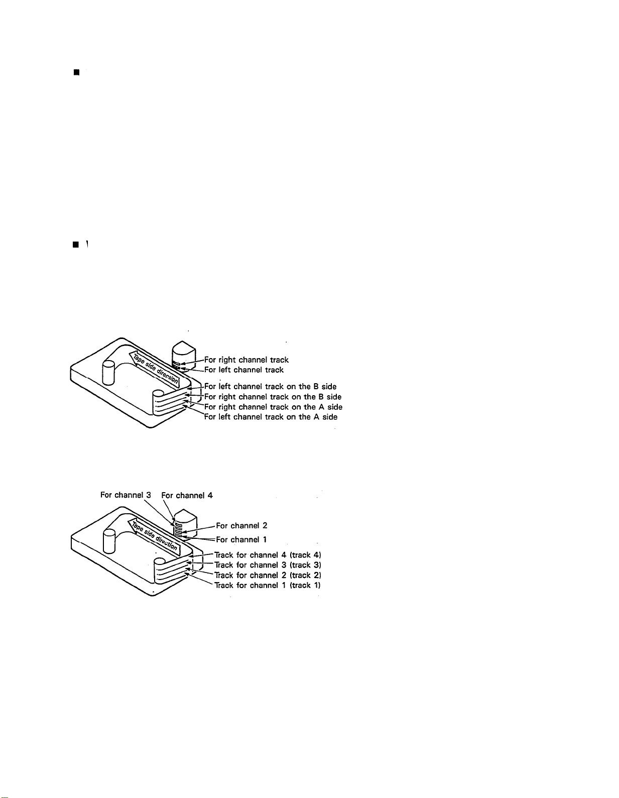
THE DIFFERENCE BETWEEN TRACKS AND CHANNELS
The words “track” and “channel” are often confused. In order to properly operate this unit, it is necessary to understand the meanings of these terms.
TRACK:
The “band” on the tape itself where a certain signal is
recorded. The tape inside a cassette has four different
tracks, enabling the recording of four distinct signals. For
conventional recordings, there are two tracks (stereo left
and right) on each side of the tape.
WHAT IS A MULTITRACK CASSETTE RECORDER?
The difference between the MT1X multitrack cassette recorder and a conventional stereo cassette deck is shown
below.
CONVENTIONAL STEREO CASSETTE DECK
CHANNEL:
The route of a signal input or output. In the input side,
this unit has four INPUT channels and two AUX chan-
nels. The output side consists of one stereo channel
(made up of two mono channels) and an AUX channel.
The diagram shows how a conventional stereo cassette
deck records and plays back music. The four tracks on
a cassette tape represent the left and right (for stereo)
sound for each side of the tape. The MT1X uses these
four tracks for single-direction recording and playback
on only one side of a cassette tape.
Conventional stereo cassette recorders always record
and play back in the same mode, with the tape side
(direction) determining which two tracks will be used.
These recorders do not allow separate selection of tracks
for recording and playback.
MT1X MULTITRACK CASSETTE RECORDER
Multitrack recorders, however, allow you to record or
playback tracks separately as you choose. This enables
a greater degree of recording and playback freedom not
possible with conventional cassette recorders.
3
Page 6
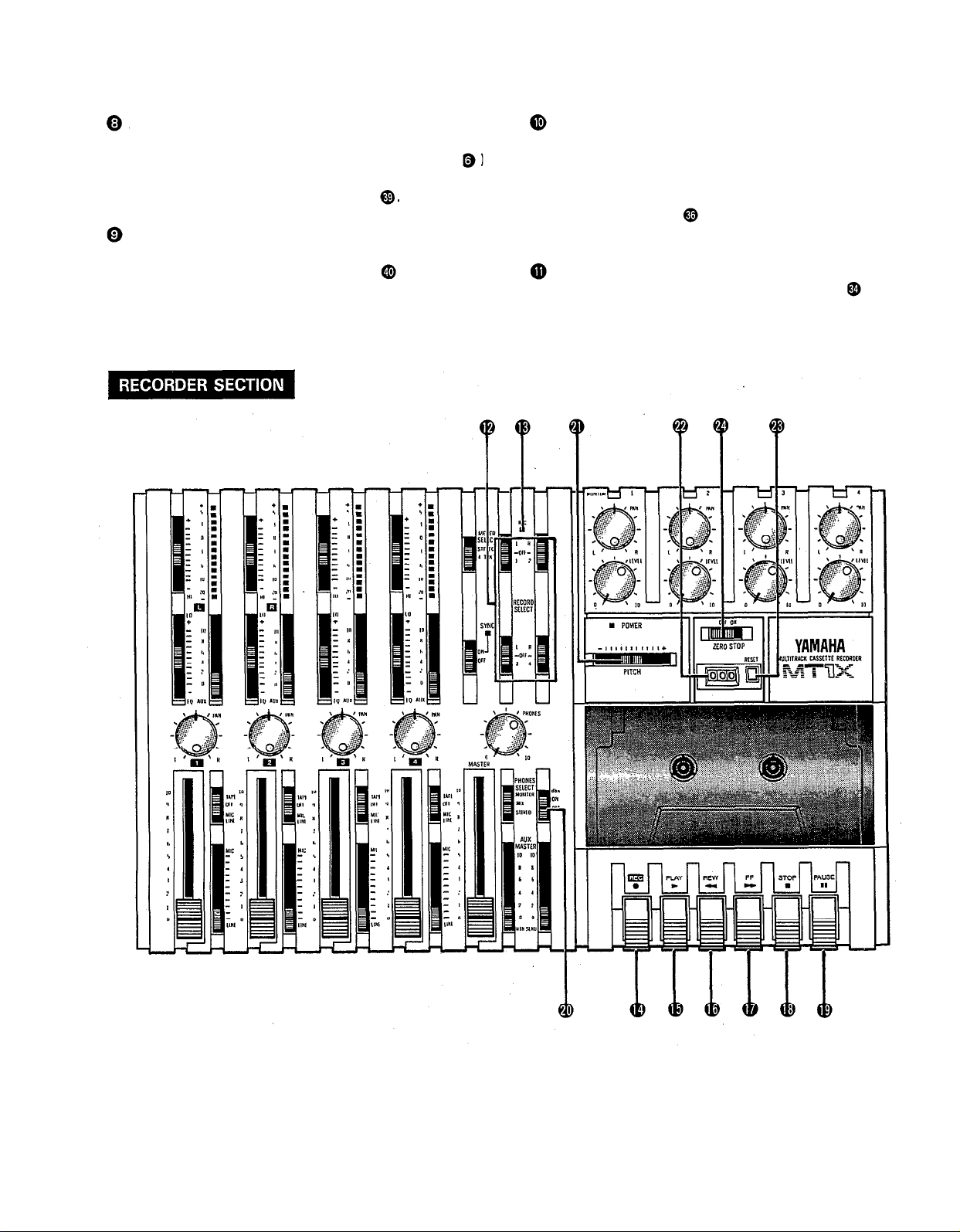
THE CONTROLS AND THEIR FUNCTIONS
This section explains the names and functions of all the knobs, sliders, and switches for the mixer, recorder, meter/
monitor, and connector sections. Familiarize yourself with them in order to take full
functions.
MIXER SECTION
advantage of the MT1X’s versatile
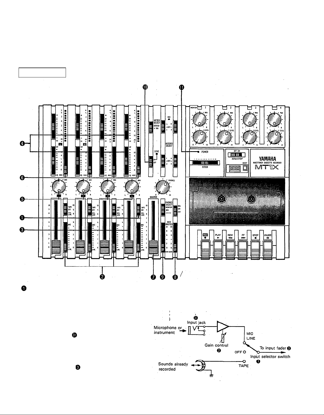
INPUT SELECTOR SWITCHES
These three-position switches are provided for each
channel. Position them according to the operation to be
performed.
MIC/LINE: Set this switch to the proper position when
the output of a microphone, keyboard instru-
ment, or electric guitar is connected to the
input jack on the front panel.
OFF:
Be sure to set the switch to this position
when the channel is not being used, or when
you don’t want to playback material already
recorded on the track. Although sliding the
input fader to the “O” position will stop
the signal, it’s a good idea to also set the
switch to OFF.
TAPE:
Set the switch to this position to playback
material which has already been recorded on
this channel. Channels 1—4 correspond to
tracks 1—4 on the tape.
4
Page 7
GAIN CONTROLS
The controls adjust the input level of the channel to
match the output level of a microphone or instrument
connected to input jack Control from -10dB to
-50db is possible. Adjust the output level of the
microphone or instrument as outlined in its instruction
booklet.
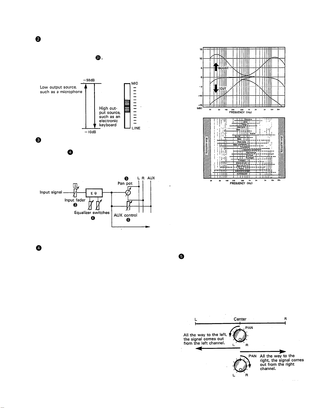
INPUT FADERS
These controls adjust the volume of the signal input, and
send it to the equalizer. Each control is used for setting the sound level of its channel when mixing it with
the signals of other channels. Position “7” on the scale
is considered ideal for the lowest noise and distortion
characteristics.
SOUND CHARACTERISTICS OF THE EQUALIZER AND
VARIOUS MUSICAL INSTRUMENTS
Be sure to set the control to “O” for channels not being
used.
EQUALIZER CONTROLS
These controls are used to adjust the tonal character-
istics of the input signal, or the channel output during
playback of previously recorded material. The LO (low)
controls adjust the frequencies centering around 100Hz,
while the HI (high) controls adjust the frequencies center-
ing around 10KHz, with a 10dB boost or cut range for
both controls. Use of these equalizer controls will help
you to get the type of sound you desire, and allow you
”,
to bring the sound“forward
and “push down” sounds at annoying frequencies.
In order to properly use these equalizers, it’s important
to understand the frequency response characteristics
of various musical instruments. This is particularly true
when trying to “change” the sound of a certain in-
strument, because you should know that instrument’s
harmonic sound components as well. For example, the
normal frequency range of a bass drum is between 50Hz
and 150Hz. To bring out this sound so you can feel it
better, the LO (low) control (which centers on the 100Hz
frequency band) can be moved up a little. But the har-
monic sound components are around 10KHz, so the HI
(high) control should also be moved up a little to achieve
the proper sound profile of the bass drum.
5
“clean up” unclear sounds,
-----Normal frequency
If accurate and comprehensive sound equalization is
required, connect a graphic equalizer or a parameteric
equalizer between the sound source and the input jack.
When recording material that you will intend to “pingpong” (see “Ping-ponging” on page 25), later, give the
input somewhat of a high boost with the Hi control to
help preserve the high frequency response when the
track is re-recorded.
PAN (PAN POT) CONTROLS
After volume level and equalizing, the input signal is sent
to these controls. During mixdown (see “Mixdown” on
page 31), each control helps determine the acoustsic
“position” of the signal in regards to the stereo field.
Turning the control all the way to the left puts the signal
all the way over to the left side of the stereo soundspace;
turning the control to the right sends the signal towards
the right. At dead center, the signal comes out equally
from the left and right channels.
These controls are also useful in ping-ponging (see “Ping-
ponging” on page 25).
----- Harmonic sound
components
Page 8
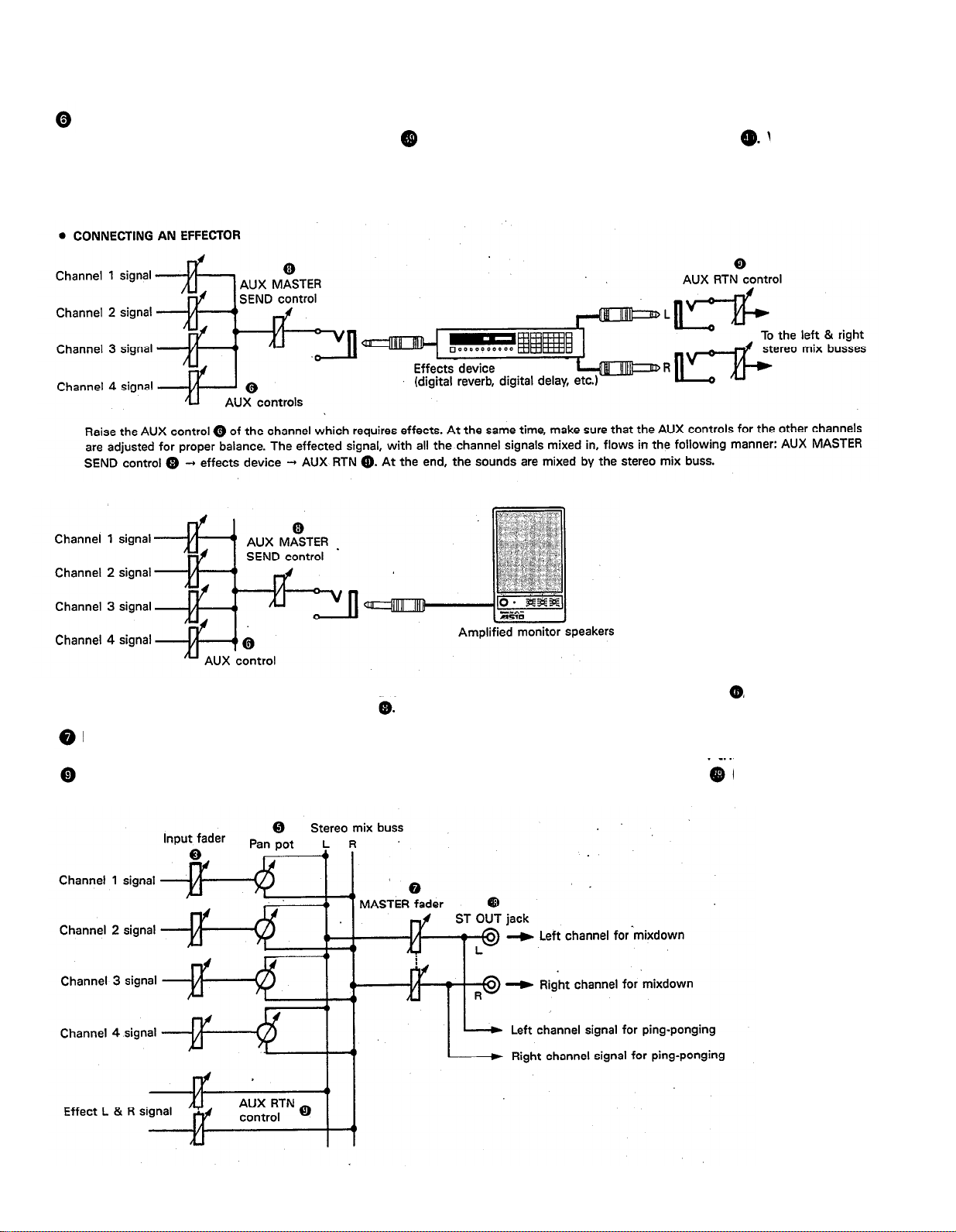
AUX CONTROLS
The MT1X is equipped with an AUX SEND jack and two (left and right) AUX RETURN jacks When special
acoustic effects are desired on a certain channel, reverbs or delay effects can be connected between these jacks to
provide only the desired effect to the desired channel. Amplified monitor speakers can also be connected to the AUX
SEND jack. Each AUX control adjusts the sources connected to the AUX SEND jack in the following manner.
•CONNECTING MONITOR SPEAKERS
Performers or sound mixers can control the level balance of the four channels (instruments) with the AUX controls
level adjusted by the AUX MASTER SEND control
MASTER FADER
This controls the level of all the input faders, as well as the final level of the effected signal of the AUX RTN control
and the sound mixed through the stereo mix buss. The output level of the ST OUT jack
at mixdown) and the recording level during ping-ponging are also adjusted with this control.
, with the total output
(the recording level
Set the control input faders at “7” for best results.
6
Page 9
AUX MA STER SEND C ONTRO L
This c o ntro l a d justs the le ve l o f the e ffe c t-m ixe d sig na ls
fro m e a c h c ha nne l (a d juste d b y e a c h AUX c o ntro l
a s we ll a s the AUX sig na l fo r m o nito ring use . The fina l
o utp ut is thro ug h the AUX SEND ja c k
No rm a lly le ft in the “ O FF” p o sitio n, this switc h sho uld
b e turne d “ O N” if this unit is to b e use d fo r sync hro nize d o p e ra tio n with MIDI p ro d uc ts like synthe size rs a nd
rhythm ma c hine s. Sync hro o p e ra tio n is e xp la ine d in the
se c tio n o n Sync ja c k o r in the Sync -Re c o rd ing se c -
A UX RETURN C O NTRO L
tio n o n p a g e 33.
This c o ntro l a d justs the inp ut le ve l o f e ffe c ts o r sub mixe rs c o nne c te d to the AUX RTN ja c k
. The le ve l o f
e ffe c t in re la tio n to the so und c a n b e se t with this
c o ntro l.
SYNC SWITC H
Po we r Ind ic a to r
This ind ic a to r lights w he n the p o w e r switc h
re a r p a ne l is turne d o n.
o n the
7
Page 10

REC O RD SELEC T SWITC HES
The se switc he s a re use d to c ho o se the sig na l to b e
re c o rd e d . The up p e r le ft switc h is fo r tra c k 1, the up p e r
rig ht switc h is fo r tra c k 2, the lo we r le ft switc h is fo r
tra c k 3, a nd the lo w e r rig ht switc h is fo r tra c k 4.
Whe n the tra c k is no t to b e re c o rd ing , se t the c o rre sp o nd ing switc h to the O FF p o sitio n. Switc h O N o nly
tho se switc he s c o rre spo nd ing to the tra c ks whic h a re
to re c o rd . The p a ne l ind ic a tio ns fo r “ L” a nd “ R” c o rre s-
p o nd to the ste re o le ft a nd rig ht sig na ls, whe re as “ 1”,
“ 2” ,“ 3”a nd “ 4” c o rre spo nd to the sig na l fro m the 1,
2, 3, a nd 4 inp ut c ha nne ls. Tho se sig na ls a re re c o rd e d
o n the ir re spe c tive tra c k whe n the switc he s a re in
p o sitio n.
NO TE: Tra c ks 1 a nd 3 c a nno t b e re c o rd e d o n the right
ste re o sig na l, a nd tra c ks 2 a nd 4 c anno t b e
re c o rd e d o n the le ft ste re o sig na l.
REC INDIC ATO R
Re c o rd ing sta tus is ind ic a te d in the fo llo wing thre e wa ys:
No indic a tio n:
All tra c ks 1—4 a re no t re c o rd ing .
Fla shing :
All tra c ks 1—4 a re in re c o rd ing sta nd b y m o d e . By
p ushing o nly the REC switc h
the ta p e is put into
the re c o rd ing sta nd b y mo d e .
Ind ic a tio n O N:
All tra c ks 1—4 a re re c o rd ing , o r in the REC p a use
mo d e . To re sume re c o rd ing d uring REC p a use , p re ss
the PAUSE switc h
REC SWITC H
Whe n this switc h is p re sse d , the PLAY switc h
a lso
mo ve s, a nd the unit g o e s into the re c o rd ing mo d e .
Ho w e ve r, if the REC O RD SELEC T switc he s fo r a ll tra c ks
1—4 a re sw itc he d O FF, no thing w ill b e re c o rd e d .
NO TE: Whe n the REC switc h is p re sse d d o w n, no ise
o c c urs whic h is re c o rd e d o n the ta p e . In o rd e r
to p re ve nt this, we re c o m m e nd e d the use o f the
PAUSE switc h
Pre ss the PAUSE switc h first,
the n p re ss the REC switc h. To sta rt re c o rd ing ,
p re ss the PAUSE switc h a g a in to shift o ut o f the
REC p a use mo d e a nd into the re c o rd ing m o d e .
PLAY SWITC H
Pre ss this switc h fo r p la yb a c k. Ho we ve r, if the inp ut
se le c to r switc h (1) o f a tra c k is no t in the TAPE p o sitio n,
the so und w ill no t b e he a rd o n the ste re o b uss.
REW SWlTC H (REWIND)
Use this switc h to re w ind the ta p e . Pre ssing it whe n
the MT1X is in the PLAY mo d e e na b le s yo u to he a r the
so und o f the ta p e while it re w ind s. This fe a ture is use ful fo r find ing the b e g inning o f a so ng o r o the r re c o rd e d
ma te ria l.
FF SWITC H (FAST FO RWARD)
Use this switc h to q uic kly a d va nc e the ta p e fo rw a rd .
Pre ssing it whe n the MT1X is in the PLAY mo d e e na b le s
yo u to he a r the so und o f the ta p e w hile it is mo ve d fo rwa rd . This fe a ture is use ful fo r c ue ing up the sta rt o f
a sub se q ue nt so ng o r o the r re c o rd e d ma te ria l o n the
ta p e .
STO P SWITC H
Pre ss this to sto p ta p e run.
PAUSE SWITC H
Pre ss this switc h to mo me nta rily sto p p la yb a c k o r
re c o rd ing in p ro g re ss. Pre ss it a g a in to re sta rt.
db x SWITC H
O rd ina ry c a sse tte ta p e s d o n’ t ha ve suffic ie nt d yna m ic
ra ng e (the le ve l d iffe re nc e b e twe e n the so fte st so und s
a nd the lo ud e st p e a ks) to a d e q ua te ly re c o rd hig hly
d yna mic music . If the d b x switc h is p ut “O N” d uring
re c o rd ing , hig hly d yna m ic music sig na ls c a n b e a d e q ua te ly ha nd le d , w hile the hiss no ise inhe re nt to c a sse tte
ta p e s is ke p t d o wn b e lo w the ra ng e o f huma n he a ring .
If the d b x switc h is ke p t “ O N” d uring re c o rd ing , it must
a lso b e ke p t “ O N” d uring p la yb a c k.
PITCH CONTROL
During re c o rd ing o r p la yb a c k, this c o ntro l c a n b e use d
to va ry the ta p e running spe e d fro m +10% to -10%.
The p itc h o f vo ic e s o r music al instrum e nts a lso va rie s
in p ro p o rtio n to ta p e sp e e d .
Und e r no rm a l c o nd itio ns, the c o ntro l sho uld b e in the
c e nte r p o sitio n. Whe n o ve rd ub b ing (p la ying b a c k a
re c o rd e d p a ssa g e while re c o rd ing ne w ma te ria l o n a d iffe re nt tra c k) the p itc h o f the p re vio usly re c o rd e d ma te ria l
c a n b e a lte re d to m a tc h the ne w ma te ria l if ne c e ssa ry.
This fe a ture c a n a lso b e use d to o b ta in c e rta in spe c ia l
e ffe c ts d uring re c o rd ing .
TAPE C O UNTER
This d isp la ys the a m o unt o f ta p e run.
RESET SWITC H
Pre ss this switc h to re se t the ta p e c o unte r to “ 000” .
Pre ssing this switc h a t the sta rt o f re c o rd ing , o r a t the
b e g inning o f a so ng , ma ke s it e a sy to c ue up the se le c tio n fro m the start.
ZERO STO P SWITC H
If this switc h is se t “ O N” d uring re wind ing , the ta p e
will sto p whe n the ta p e c o unte r re a c he s “ 999” . During
multitra c k re c o rd ing , this fe a ture is c o nve nie nt fo r
re p e a te d p la yb a c k o r re c o rd ing o p e ra tio ns a fte r re wind .
8
Page 11
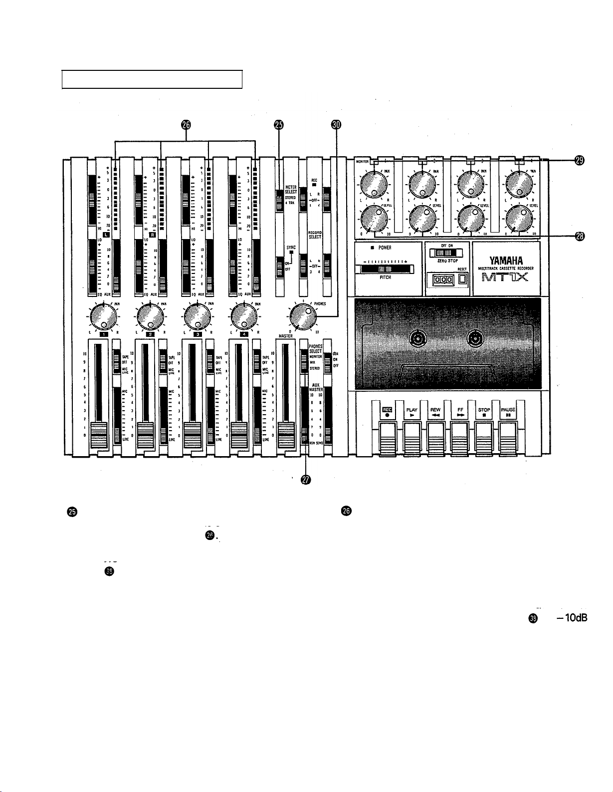
METER A ND MO NITO R SEC TIO N
METER SELEC T SWITC H
This switc h is use d to se le c t the sig na l fo r le ve l ind ic a tio n b y the Pe a k Le ve l Me te rs
STEREO Po sitio n:
The le ve l o f the sig na l o utput thro ug h the ST O UT
ja c ks
is ind ic a te d . The m e te r o n the fa r le ft sho ws
the le ve l o f the Le ft c ha nne l o f the ste re o sig na l, w hile
the se c o nd m e te r fro m the le ft sho w s the le ve l o f the
Right c ha nne l. Se tting to this p o sitio n d uring p ing p o ng ing o r mixdo wn o p e ra tio ns e na b le s e a sy re a d ing
o f the re c o rd ing le ve l.
4 TRK Positio n:
Se t the switc h in this p o sitio n to d ispla y the le ve l o f
e a c h tra c k. Sta rting fro m the fa r le ft, e a c h me te r c o r-
re spo nd s to tra c ks 1—4. During p layb a c k, the p la yb a c k le ve l is d isp la ye d ; d uring re c o rd ing , the re c o rd ing le ve l is d isp la ye d . Se tting the switc h to this p o sitio n d uring o ve rd ub b ing e na b le s e a sy re a d ing o f the
re c o rd ing le ve l.
9
PEA K LEVEL METERS
The re a re 14 LED ind ic a to rs in e a c h m e te r w hic h sho w
a ra ng e fro m - 20d B to + 5d B. During re c o rd ing , se tting
le ve ls high (b ut b e lo w the p o int w he re the re c o rd ing
b e c o m e s d isto rte d ) will e nsure the g re a te st d yna mic
ra ng e w ith the lo we st p o ssib le no ise . An id e a l p o int is
whe n the LED ind ic a to rs fo r 0d B a nd a b o ve fla sh o c c a sio na lly.
During ste re o sig na l le ve l ind ic a tio n, the a c tua l
sp e c ifie d o utput fro m the ST O UT ja c ks
(a t a 50K o hm lo a d ) w he n the LED
ind ic a to rs sta rt to
is
fla sh a t 0d B.
Page 12
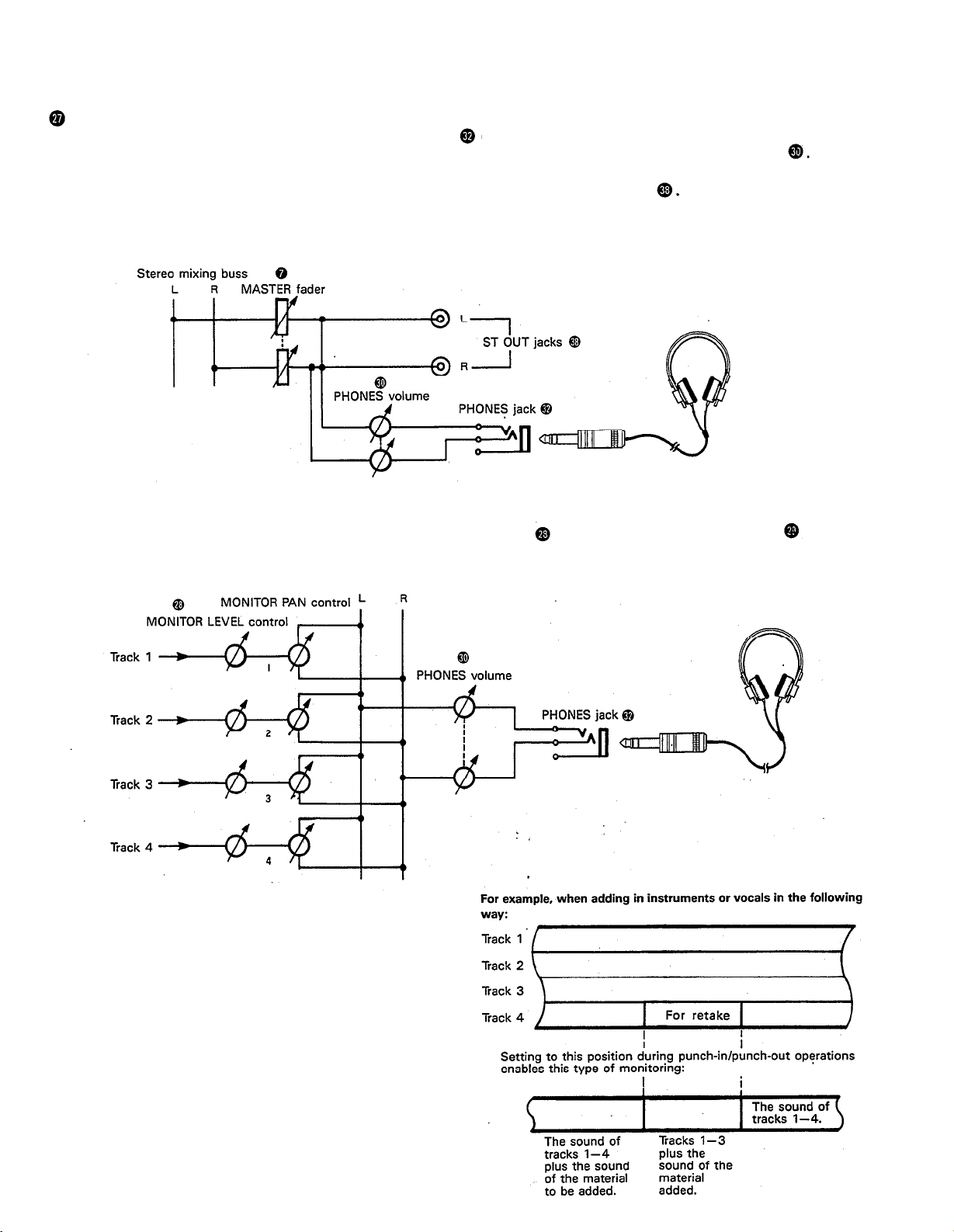
PHO NES SELEC T SWITC H
Yo u c a n p lug a se t o f he a d p ho ne s into the PHO NES ja c k
o n the fro nt p a ne l to mo nito r the so und . This switc h
is use d to se le c t the sig na l to b e mo nito re d . C o ntro l the vo lum e le ve l with the PHO NES vo lume c o ntro l
STEREO Po sitio n:
Put the switc h in this p o sitio n to mo nito r the sig na l o utp ut thro ug h the ST O UT jac ks
The Le ft a nd Rig ht c ha nne ls o f the ste re o sig na l will b e he a rd thro ug h the he a d p ho ne s.
Whe n se tting to this p o sitio n d uring ping -p o ng ing o r m ixdo wn o pe ra tio ns, the m ixe d sig na l o f a ll the instrum e nts
c a n b e mo nito re d .
MO NITO R Po sitio n:
This p o sitio n is fo r m o nito ring the sig na l o f e a c h tra c k. Yo u c a n fre e ly m o nito r w hile mixing the so und o f e a c h tra c k
d uring re c o rd ing o r p la yb a c k. Using the MO NITO R LEVEL C o ntro ls a nd the MO NITO R PAN C o ntro ls
, se t the
d e sire d le ve l a nd p o sitio n fo r e a c h tra c k.
Tra c k
MIX Po sitio n:
This p o sitio n a llo ws yo u to simulta ne o usly mo nito r
b o th the so und he a rd in the STEREO p o sitio n a nd the
so und he a rd in the MO NITO R po sitio n. Se tting to this
p o sitio n d uring p unc h-in/ p unc h-o ut o p e ra tio ns will
e na b le the typ e o f mo nito ring sho w n b e lo w. (Re fe r to
“ Punc h-in/ Punc h-o ut” o n p a g e 27).
10
Page 13
MO NITO R LEVEL C O NTRO LS
Whe n se tting the PHO NES SELEC T Switc h
to the
MO NITO R po sitio n, the se le ve l c o ntro ls a re use d fo r e a c h
tra c k to a c hie ve a le ve l b a la nc e fo r e a sy m o nito ring . Use
the se c o ntro ls fre e ly a nd ind e p e nd e ntly to m a inta in a
d e sire d le ve l b a la nc e d uring o ve rd ub b ing o p e ra tio ns,
whe n the a d d itio n o f a ne w sig na l c ha ng e s the vo lume .
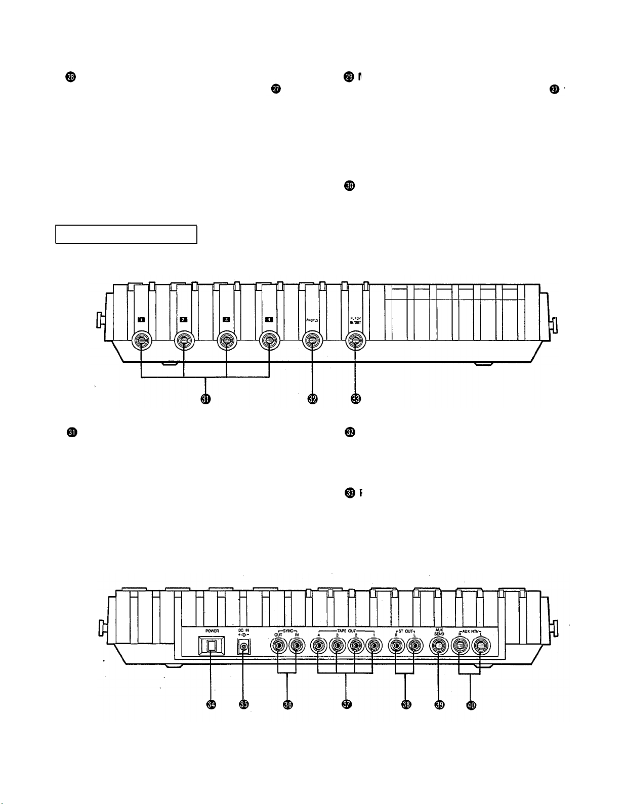
C O NNEC TO R SEC TIO N
FRO NT PANEL
MO NITO R PA N C O NTRO LS
Whe n se tting the PHO NES SELEC T Switc h
to the
MO NITO R po sitio n, use the se p a n c o ntro ls fo r e a c h tra c k
to a c hie ve the d e sire d ste re o p o sitio ning fo r e a c h tra c k.
Use the se c o ntro ls fre e ly a nd ind e p e nd e ntly to m a inta in
the d e sire d ste re o p o sitio n b a la nc e d uring o ve rd ub b ing
o p e ra tio ns, whe n the a d d itio n o f a ne w sig na l c ha ng e s
the ste re o im a g e .
PHO NES CO NTRO L
This c o ntro l a d justs the vo lume o f the he a d p ho ne s (Se e
p a g e 9).
INPUT JAC KS
The se fo ur ja c ks a re fo r the c o nne c tio n o f mic ro pho ne s
o r e le c tric a nd e le c tro nic instrum e nts. With a hig h inp ut
im p e d a nc e o f 10K o hms, a nd a sp e c ifie d inp ut le ve l ra ng e
PHO NES JA C K
Plug a se t o f he a d p ho ne s into this ja c k fo r m o nito ring .
Ple a se use he a d p ho ne s ra te d fro m 8-—0 o hms fo r b e st
re sults.
o f -10d B to -50d B, a wid e va rie ty o f instrum e nts a nd
mic ro p ho ne s c a n b e use d .
Whe n d ire c tly c o nne c ting a n e le c tric g uita r, the use o f
a n spe c ia l e le c tric g uita r p re a mp to inc re a se the inp ut
PUNC H IN/ O UT JAC K
By c o nne c ting the o ptio na l FS-1 fo o tswitc h to this ja c k,
yo u c a n c o ntro l punc h-in/ p unc h-o ut o p e ra tio ns. b y fo o t.
le ve l will a ssure re c o rd ing s o f b e tte r so und q ua lity.
REAR PANEL
11
Page 14

POWER SWITCH
This switch turns on the MT1X. When switching the unit
on or off, make sure that the Input Faders and the
AUX RTN Control
are at the “0” position.
DC IN JACK
Connect the supplied AC adaptor to this terminal. To prevent damage, use only the AC adaptor supplied with this
unit.
SYNC IN/SYNC OUT JACKS
These jacks are used during synchronized operation with
MIDI-equipped instruments. Use the optional YMC10
MIDI Converter to connect the instruments through
these jacks, and set the SYNC switch on the mixer section to “ON”. For a detailed explanation, refer to “SyncRecording” on page 33.
TAPE OUT JACKS
These jacks directly output the signal of each track. During playback, the signals of the tracks being played are
output. During recording, the signals of the tracks being recorded are output. Since the output levels cannot
be adjusted, set the volume by adjusting the output levels
on the instruments themselves. These jacks can be conveniently used in the following ways:
Another 4-track recorder can be connected for direct
dubbing of all four channels.
An external mixer can be connected for mixdown.
ST OUT JACKS
The mixed signals of each channel (and each track) are
output in stereo signal through these jacks. Since these
jacks output the final mix, a stereo cassette deck can
be connected. These jacks can also be used as follows.
The MT1X can be used as a sub-mixer, with the out-
put sent to a main mixer through this jack.
A stereo amplifier or powered monitor speakers can
be connected through this jack.
AUX SEND JACK
This jack outputs the mixed signal from the Aux bus, and
is used as an output terminal for the connection of an
effects device. This can also be used as an additional
monitor output.
AUX RTN JACKS
These jacks are used to input the signal from an effects
device back into the MT1X. As well, the mixed output
from an external mixer can be connected to these jacks.
Please note that if only a single plug is inserted into either
one of these jacks, the signal will be sent to both Left
and Right channels. This is useful if the effects device
being used is mono.
12
Page 15

C O NNEC TIO N EXAMPLES
BA SIC C O NNEC TIO N LA YO UT FO R MULTITRAC K REC O RDING
13
Page 16

ABO UT C A SSETTE TAPES
This unit is d e sig ne d to b e use d o nly w ith C hro me -
p o sitio n ta p e , a nd w ill no t wo rk pro p e rly w ith Fe rric hro m e ta p e fo rm ula tio ns. C rO
ta p e (Bia s: HIG H; EQ :
70µs) sho uld b e use d . Also , the use o f C -120 ta p e s is
no t re c o m me nd e d b e c a use the y e xhib it p o o re r p e rfo rma nc e , a nd c a n b e the c a use o f e q uip m e nt fa ilure .
Pre ve nting a c c ide nta l e ra sure o f re c o rd ing s
To ke e p fro m ina d ve rte ntly e ra sing a p rize d re c o rd ing , a ll
c a sse tte ta p e s ha ve re c o rd p ro te c tio n ta b s a lo ng the to p
e d g e o f the c a sse tte she ll. If this tab is b ro ke n o ut using
a sc re wd rive r o r a ny o the r a p p ro p ria te imp le m e nt, it will
no t b e p o ssible to re c o rd o n the c o rre spo nd ing sid e o f
the ta p e . This will p ro te c t yo ur re c o rd ing s fro m a c c id e nta l
e ra sure . Fo r 4-tra c k re c o rd ing , it’ s ne c e ssa ry to b re a k o ut
the ta b s fo r b o th the A a nd B sid e s o f the ta p e .
Whe n yo u’ d like to re c o rd o ve r a ta p e with the ta b s
b ro ke n o ut, just c o ve r the ho le s (w he re the ta b s we re )
with ta p e .
PREVENTING AC C IDENTAL TAPE ERASURE:
Ta king up ta pe slac k
If the ta p e is use d w he n it is sla c k, o r so me p o rtio n o f
the ta p e is o ut o f the c asse tte she ll, the re is a risk it
ma y b e c o me ta ng le d a ro und the c a p sta n o r p inc hro lle r.
In o rd e r to c o rre c t this, inse rt a p e nc il o r b a llp o int p e n
into the c e nte r o f o ne re e l, a nd ro ta te to ta ke up lo o se
ta p e sla c k.
Sto ring c a sse tte ta p e s
To p re ve nt ta p e sla c k, fit a sto p p e r into the tap e o r ke e p
ta p e s in the ir c a se s. Do no t sto re ta p e s in d ire c t sunlig ht,
o r in p la c e s with hig h he a t o r hum id ity, a s this ma y
d a ma g e the ta p e s. Also , ke e p the ta p e s a w a y fro m
ma g ne tic fie ld s, suc h a s ne a r te le visio ns o r spe a ke rs,
b e c a use the re c o rd ing s c a n b e e ra se d o r so nic a lly a lte re d
to so me d e g re e .
Recording over a tape with the tabs broken out
• Pla ying ta pe s re c o rde d o n o the r c a sse tte
re c o rde rs
Whe n p la ying No rma l-p o sitio n ta p e s, o r ta p e s e nc o d e d
with Do lb y B no ise re d uc tio n the MT1X, the fo llo wing
ste p s a re a d vise d :
1) Pla ying No rm a l-p o sitio n ta pe s — m o ve the HI
e q ua lize r fa d e r in the “ + ” d ire c tio n to b o o st the hig h
fre q ue nc ie s until the so und is sa tisfa c to ry.
2) Pla ying ta p e s e nc o de d with Do lby B NR— p ut the
d b x switc h in the “ O FF” p o sitio n, a nd m o ve the HI
e q ua lize r fa d e r in the “
– ” d ire c tio n to re d uc e the
hig h fre q ue nc ie s until the so und is sa tisfac to ry.
14
Page 17

ATTAC HING THE STRA P
The MT1X c a n b e e a sily c arrie d w ith the sup p lie d c a rrying stra p . He re ’ s ho w to a tta c h it.
Push o n the slit to o p e n the sto p p e r, a nd ha ng it o n
the p e g .
Slid e the stra p to the d e sire d p o sitio n a nd lo c k the
sto p p e r in p la c e .
WHEN USING THE BATTERY PAC K
With the o p tio na l PA11 Ba tte ry Pa c k, the MT1X c a n b e o p e ra te d b y b a tte rie s in p la c e s whe re the re is no AC o utle t
a va ilab le . He re ’ s ho w to se t it up .
• PUTTING IN THE BATTERIES
Slid e o ff the b a tte ry c o ve r o n the b o tto m o f the b a t-
• A TTA C HING THE BA TTERY PA C K
Alig n the b a tte ry p a c k o n the le ft sid e o f the MT1X.
te ry p a c k.
Slid e it o n, a nd tig hte n the b a tte ry p a c k m o unting
sc re w with a c o in o r sc re wd rive r. The b a tte ry p a c k
is no w firmly a tta c he d .
Inse rt 10 “ C ” b a tte rie s a s sho w n.
Put 7 o n the b o tto m
Re p la c e the b a tte ry c o ve r.
15
The n p ut 3 o n to p
NO TES:
Whe n using the b a tte ry pa c k a s a p o w e r sup p ly, re m o v e the AC
a d a p to r.
The b a tte ry p a c k c an o nly sup p ly p o we r to the MT1X whe n it is
p rop e rly a tta c he d .
The MT1X wa s de sig ne d fo r ind o o r use . Avo id using it a re a s o f hig h
he a t o r humid ity, o r in d usty pla c es.
If the b a tte ry p a c k isn’ t g o ing to b e use d fo r a n e xte nd e d p e rio d
o f time , re m o ve the b a tte rie s insid e .
Ba tte ry life : a b o ut 2 ho urs d uring 2 c ha nne l re c o rding with a he a d -
p ho ne o utp ut o f 10m W + 10m W.
Page 18

MULTITRAC K REC O RDING TEC HNIQ UES
Be fo re yo u try to a tte mp t a multitra c k re c o rd ing o n yo ur
o wn, it’ s a b so lute ly e sse ntia l tha t yo u und e rsta nd the
func tio n o f a ll the c o ntro ls, switc he s, a nd c o nne c to rs in
e a c h se c tio n. In a d d itio n, yo u sho uld sp e nd a n a d e q ua te
a m o unt o f tim e to fa m ilia rize yo urse lf with the b lo c k
d ia g ra m o n p a g e 35. It m a y a p p e a r ha rd to und e rstand
a t first, b ut a fte r c a re fully lo o king it o ve r, yo u’ ll find tha t
it’ s no t o nly e a sy to fo !lo w, b ut q uite use ful in und e rsta nd ing the va rio us sig na l flo ws invo lve d in using the
C MX1. The numb e rs o n the b lo c k d ia g ra m fo r the c o ntro ls, sw itc he s, a nd c o nne c to rs c o rre spo nd to tho se
use d in the se c tio n title d “ The C o ntro ls, a nd The ir
Func tio ns”.
O NE EXA MPLE O F A MULTITRAC K
RECO RDING PRO C ESS
Multitra c k re c o rd ing is usua lly use d to re c o rd a rhythm
se c tio n, with o ve rd ub b ing a nd p ing -p o ng ing o p e ra tio ns
a ssisting in m ixing the p a rts o f the va rio us music ia ns in
the p ro p e r b a la nc e . Fina lly, the ta p e is mixe d d o wn to
p ro d uc e a ste re o ma ste r ta p e .
The se a re the ste p s in o ur e xa m ple:
Re c o rd the d rums o n tra c k 1
Re c o rd the b a ss o n tra c k 2
Re c o rd the rhythm g uita r o n tra c k 3
Ping -p o ng ing tra c ks 1 — 3 o nto tra c k 4
(fre e ing tra c ks 1—3)
Re c o rd the ke yb o a rd s o n tra c k 1
Re c o rd the le a d g uita r o n tra c k 2
Re c o rd the vo c a ls o n tra c k 3
Mixd o wn tra c ks 1
ma ste r ta p e
— 4 to p ro d uc e a ste re o
me re insta nt, it’ s no t a p ro b le m. Ho we ve r, if the y’ re p e a king o ut fo r mo re tha n a se c o nd o r two , the n d isto rtio n
ma y b e c o me a p ro b le m. It’ s a lso imp o rta nt to re m e m b e r
tha t d isto rtio n a t lo w e r fre q ue nc ie s is le ss a p p a re nt tha n
d isto rtio n a t hig he r fre q ue nc ie s.
db x SYSTEM
Ke e p the d b x switc h “ O N” to e xp a nd d yna mic ra ng e a nd
to re d uc e inhe re nt tap e no ise .
STEREO PO SITIO NING
It’ s im p o rta nt to think a b o ut the a c o ustic “ p o sitio n” o f
a ll the instrume nts we ll b e fo re yo u sta rt yo ur m ultitra c k
re c o rd ing . Yo u sho uld ta ke into a c c o unt a c e rta in a mo unt
o f no ise c a use d b y p ing -p o ng ing a nd m ixd o w ns p la n-
ne d fo r la te r o n.
He re ’ s o ne e xa mp le o f a c o ustic p o sitio ning . Se t the b a ss
d rum a nd the sna re d rum c e nte r, with the to m to m s a nd hig h ha t se t o ff to e ithe r sid e to b ring o ut the
“ ste re o ” e ffe c t. The b a ss a nd o the r “ he a vy” instrume nts
sho uld b e in the c e nte r, with the ke yb o a rd s to the le ft
a nd the g uita r to the rig ht. So lo instrum e nts a nd vo ic e s
sho uld spa n b o th rig ht a nd le ft. So lo instrume nts with
a ste re o o utp ut c a n ha ve the ir le ft c ha nne l c o nne c te d
to a d e la y m a c hine , w hile the rig ht c ha nne l is re c o rd e d
d ire c tly. Yo u c a n p ro b a b ly think o f m a ny o the r d iffe re nt
wa ys to “ a rra ng e ” the so und stag e .
EQ UA LIZATIO N A ND EFFEC T PRO C ESSING
Eq ua liza tio n a nd e ffe c t p ro c e ssing a re usua lly a d d e d a t
the p ing -p o ng a nd m ixd o w n sta g e s. In m ultitra c k re c o rd -
ing , the se typ e s o f sig na l p ro c e ssing c an b e d e c id e d o n
la te r, a nd e m p lo ye d to a ny d e g re e ne c e ssa ry. Ho we ve r,
the MT1X is limite d in the numb e r o f e ffe c ts w hic h c a n
b e use d d uring m ixd o wn, so it’ s b e st to use the m d ur-
ing the initia l re c o rd ing sta g e s.
BEFO RE REC O RDING
RECO RDING LEVEL
In ma king a g o o d re c o rd ing , the mo st imp o rta nt ste p is
se tting the id e a l re c o rd ing le ve l. If the le ve l is to o lo w ,
the re c o rd ing w ill c o nta in a lo t o f no ise a nd hiss; if the
le ve l is to o hig h, the re c o rd ing w ill so und d isto rte d a nd
unc le a r. Se t the re c o rd ing le ve l a t a fa irly hig h le ve l, b ut
no t so hig h a s to re sult in a ny no tic e a b le d isto rtio n.
The C MX1 is e q uip p e d w ith p e a k le ve l m e te rs whic h
sho w the le ve l o f e a c h tra c k, a s we ll a s the le ve l o f the
ste re o o utp ut sig na l. Use the se me te rs to he lp yo u se t
the id e a l re c o rd ing le ve l, b e c a use the huma n e a r ha s
d iffic ulty in d e te c ting d isto rtio n imm e d ia te ly. If the le ve l
me te rs “ p e a k o ut” (sho w the ma xim um re a d ing ) in a
Mo nitoring
In a d d itio n to c irc uits fo r sig na l re c o rd ing , this unit a lso
fe a ture s a se p a ra te m o nito r c irc uit to a llo w the p e rfo rm e r
to m o nito r the le ve ls a nd p o sitio ning o f the re c o rd ing in
p ro g re ss thro ug h a p a ir o f he a d p ho ne s. In this c a se , se t
the PHO NES SELEC T switc h to the “ MO NITO R” p o sitio n. Ad just the vo lum e le ve l a nd ste re o po sitio ning o f
e a c h tra c k with its MO NITO R LEVEL a nd MO NITO R PAN
c o ntro ls.
In a d d itio n, p o w e re d m o nito r spe a ke rs c a n b e d ire c tly
c o nne c te d to the ST O UT ja c ks o r the AUX SEND ja c k,
tho ug h this ma ke s it im p o ssib le to use the se ja c ks fo r
e xte rna l re c o rd ing o r e ffe c ts. Using sp e a ke rs d uring
re c o rd ing o ff line s p re se nts no p ro b le m s, b ut whe n
mic ro p ho ne s a re use d , fe e d b a c k c a n re sult whe n the
mic ro p ho ne p ic ks up so und fro m the sp e a ke rs. In this
c a se , mo nito ring thro ug h he a d p ho ne s b e c o me s a b so lute ly ne c e ssa ry.
16
Page 19

MULTITRACK RECORDING
PLAN YOUR RECORDING
A clear plan is essential before you begin multitrack
recording. If you begin cold, without regard to all the
steps involved, you may “record yourself into a corner”
by running out of available empty tracks, missing the
chance to add effects at the proper points, losing control over the final stereo positioning of the instruments,
and creating the need for more ping-pong and mixdown
recording operations than really necessary. Although you
can perform ping-pong and mixdown operations without
limit, a certain amount of noise and sound degradation
results during these operations. It’s best to hold ping-
ponging down to 1 or 2 operations in order to achieve
good sound quality.
So before you start, plan your recording carefully — what
order the parts will be recorded in, what instruments will
go on which tracks, how and when effects will be used,
when recorded tracks will be ping-ponged, and what sort
of end result is desired. The recording process of the ex-
ample we will explain in this section is illustrated on page
16.
—
Sig na l ro ute whe n re c o rding drum s —
RECORDING THE DRUMS
The drums will be recorded on track 1. In recent years,
drum machines and rhythm machines have made an
appearance, with Yamaha coming out with the highperformance RX11, RX15, and RX21 Digital Rhythm Programmers. However, for this example we will be recording a conventional set of drums. Though many will be
recording with electronic drums, the basic approach is
the same.
The MT1X has four input jacks, enabling the setting up
of the four microphones for recording, as shown in the
diagram. Through the MT1X’s mixing section, the sounds
recorded by these microphones are mixed down onto
track 1.
YAMAHA’s REV7 Digital Reverberator can be used for
reverb effects. It also features echo and delay programs
as well as gate reverb and even kick drum programs
enabling you to freely obtain various effects to suit
each individual song.
17
Page 20

— Drum Recording Procedure —
1. Connections
Plug the AC adaptor into an AC outlet, and insert
the small round plug into the DC IN jack.
Plug the four microphones into input jacks 1-4.
Plug a pair of monitor headphones (rated 8-40
ohms) into the PHONES jack.
When using an effect, connect it between the AUX
SEND jack (input) and either of the AUX RTN jacks
(output).
2. Getting ready
Lift open the cassette door and insert a chrome
position (CrO2) tape.
Return all the switches and controls to their nor-
mal positions, referring to the control panel illustra-
tion on pages 4~9.
Turn the power switches on for the effect and
microphones, and then turn the MT1X “ON”. The
POWER indicator will light.
3. Setting up the recorder section
Press the RESET switch to return the counter to
“000".
Turn “ON” the ZERO STOP switch.
Turn “ON” the dbx switch.
Set the RECORD SELECT switch 1 to the “L” posi-
tion. This is to record the Left stereo signal onto
track 1. The REC indicator will begin flashing.
Bias: HIGH, Eq: 70us.
18
Page 21

4. Setting the monitor and meter sections
Set the PHONES SELECT switch to the “STEREO”
position.
Set the PHONES volume to around “7”.
Make sure the METER SELECT switch is in the “4
TRK” position.
5. Adjusting the input level
Set all of the input switches to the MIC/LINE
position.
Set the MASTER fader to “7”.
Set the PAN controls for all channels between the
center and the extreme “L" position, as shown.
19
Push the input fader for channel 1 up to “7”.
When the drums start playing, slide the gain con-
trol for channel 1 towards the “MIC”, direction, stop-
ping when the “+3” indicator on the far left level
meter flashes occasionally on the sound peaks.
Pull the input fader for channel 1 back down to “0”.
-The proper input level for channel 1 is now set.—
Set the input fader for channel 2 to “7”.
While the drums are being played, slide the gain con-
trol for channel 2 towards the “MIC” direction, stopping when the “+3” indicator on the far left level
meter flashes occasionally on the sound peaks.
Pull the input fader for channel 2 back down to “0’:
-The proper input level for channel 2 is now set.-
Set the input levels for channels 3 and 4 the same
way.
Page 22

*Explanation diagram for steps to and to .
6. Adjusting level balance and equalization
characteristics
Adjust channel faders 1 ~4 to achieve the desired
recording level balance.
Adjust the equalizers for 1~4 to obtain the desired
sound character for each individual channel. (If
you’re thinking of ping-ponging these tracks after-
wards, it’s a good idea to add a little boost on the
HIGH EQ because high frequencies can be slightly
diminished during the ping-pong re-recording
process).
Set the effect level for each channel with the AUX
controls. Then, adjust the overall mix of effect
signal to input signal with the AUX MASTER SEND
control.
If necessary, go over steps
until everything is just right.
Adjust the master recording level with the MASTER
fader, setting it at the point where the “+3” in-
dicator on the far left level meter flashes occa-
sionally on the sound.peaks.
to
several times
7. Recording
Push the PAUSE switch to start recording. Just
before the musician starts playing, be sure to
“count” out loud to help you get the timing right
on the other tracks during overdubbing later on.
When the music sequence is over, press the STOP
switch to stop the recording. Then, press the REW
switch, and the tape will rewind to a point just
before the beginning
and stop.
— Drum Recording Completed —
Track 1
Track 2
Track 3
Track 4
“999” on the tape counter
20
Page 23

Make sure this switch is in the “4 TRK” position.
Set this so you can monitor track 1.
8. Post recording check
Return all switches and controls to their normal
positions.
Set the PHONES SELECT switch to the “MONITOR”
position, turn MONITOR LEVEL control 1 to “7’:
then turn the PHONES volume control to about “7”.
Make sure the METER SELECT switch is set to “4
TRK".
Press the PLAY switch, and check the sound recorded on track 1 by headphones, and by looking at the
level meter.
Press to check the recording on track 1,
then rewind.
*Explanation diagram of steps to
At this point, if the track is recorded properly and there
doesn’t seem to be any problems, press the REW switch
and reset all the knobs and controls to their normal positions. Now it’s time to record the bass.
If the recording is not to your satisfaction, you can rerecord the whole track. Or you can use the “punchin/punch-out” technique to record over a certain spot on
the tape. It’s explained on page 27.
21
Page 24

RECORDING THE BASS GUITAR BY OVERDUBBING
Overdubbing is the playing back previously recorded
tracks while recording a new instrument on a different
track. With this technique, it’s possible for one musician
to play many different instrumental parts on a single
recording. If you’re multitalented, multitrack overdub-
bing can clone you into your own group.
Now, we’re going to record a bass guitar on track 2 to
synch with, or match, with the drum part already record-
ed on track 1. There are two ways to record the bass:
place a microphone in front of the bass amp, or run a
direct line from the bass into the recorder.
If you’re after a really clear recording, direct line recording is the way to go. If you’re using an effect of some
sort, you’ll want to run a noise gate thru the final stage
of the effect. This is true with all electrified musical
instruments.
Another idea is to use the Yamaha GC2020 comp/limiter.
In addition to the compresser and limiter functions, the
noise gate function can prove to be very convenient.
— Signal Path when Recording the Bass Guitar —
TRK2
22
Page 25

— Bass guitar recording procedure —
1. Connections
Connect everything through input jack 2 as follows.
If the GC2020 is being used, connect it between
the amplifier and input jack 2.
When not using a bass amp, the use of a direct box
is recommended.
Connect the monitor headphones. Until the mix-
down process, only use headphones and avoid
using monitor speakers. (This also goes for the rest
of the steps.)
23
2. Setting the recorder
Make sure the tape has been rewound to the “999”
point on the counter. (This also goes for the rest
of the steps.)
Keep the ZERO STOP switch “ON” until mixdown.
(This also goes for the rest of the steps.)
Keep the dbx switch “ON” until mixdown. (This also
goes for the rest of the steps)
Set the RECORD SELECT position to “2”, the REC
indicator will flash to show that the bass guitar con-
nected to input jack 2 will be recorded on track 2.
Press the pause switch to start the recording. The
REC indicator will light up completely.
3. Setting the monitor and meter sections
Set the PHONES SELECT switch to the “MONITOR”
position.
Turn MONITOR LEVEL controls 1 and 2 to about “7’:
Set the PHONES volume level to about “7”.
Make sure the METER SELECT switch is in the “4
TRK” position.
Page 26

Equalizer controls
Press the PAUSE button and
adjust the monitor levels
Set to the MIC/LINE position
Set by the reading on the level meter
Push up to about “7”
Set after setting equalization
4. Adjusting the Input level
Set the input selector switch to the MIC/LINE
position.
Push input fader 2 up to about “7”.
Start playing the bass guitar, and slide gain control
2 towards the “MIC” direction, stopping when the
“+3” indicator on the level meter second from the
left flashes occasionally on the sound peaks.
5. Adjusting the recording level and sound
characteristics
Operate the equalizer controls for channel 2 to get
the desired tone. (If you plan to ping-pong this track
later, boost up the treble a little bit with the HIGH
EQ control.)
Use input fader 2 to adjust the recording level ac-
cording to the reading on the meter second from
the left.
6. Adjusting the monitor sound
Press the PAUSE switch to start the tape, and set
the sound balance of the bass guitar and drums.
If necessary, control the combined volume level
with the PHONES volume control. Now, using
MONITOR PAN controls 1 and 2, decide the left/
right stereo positioning of the two tracks. (During
this, the bass guitar will be recorded on track 2.)
*Explanation diagram for steps to
After you have adjusted the monitor levels and pans
to your satisfaction, rewind the tape and set the
recorder into the REC PAUSE mode.
7. Recording
Press the PAUSE switch to start recording. While
monitoring through headphones, the bass player
should play along in synch with the drum track.
When the musical segment is over, stop and rewind
the tape.
— Bass Guitar Recording completed —
Track 1
Track 2
Track 3
Track 4
8. Post recording check
Just press the play switch to check to see that the
track was recorded properly.
Set all switches and controls back to their normal
positions.
24
Page 27

RECORDING THE RHYTHM GUITAR
Record the rhythm guitar on track 3 to synch with the
drums on track 1 and the bass guitar on track 2. Recording preparations and operations are the same as when
recording the bass guitar. If effects are being used, connect them just before the input jack.
PING-PONG < PING-PONG RECORDING >
After the rhythm section has been recorded on tracks
1
— 3, only track 4 remains as an empty, spare track.
Since there are three more parts to be recorded, more
tracks will be needed.
The ping-pong technique (sometimes called bouncing, or
track transfer, or collapsing tracks) shown here allows
you to re-record these three tracks onto one track, thus
freeing up tracks for other recording operations. You can
also add other new parts during the ping-pong process.
As long as there are empty tracks, you can ping-pong
from one or more tracks to another as many times as
you like.
However, each time a track is ping-ponged onto another
track, some degradation in sound quality occurs. Most
noticeable is a loss of high frequency sounds, or “tre-
ble”. Therefore, it’s best to plan for only 1 or 2 ping-pong
operations to preserve the sound quality of the instru-
ments you record. Now, let’s get started.
— Signal Path during Ping-pong Recording —
Track 1
Track 2
Track 3
Track 4
Track 1
Track 2
Track 3
Track 4
Recording signal to the input
Signal displayed by the meter
Monitor signal
25
Page 28

— Ping-pong Recording Procedure —
Equalizer controls
Make sure it’s set to “4 TRK”
Set the “R” position
Turn to about “7”
1. Setting the recorder
Set the RECORD SELECT switch to the “R” posi-
tion to mix the sound of the drums, bass guitar, and
rhythm guitar through the stereo buss. The REC in-
dicator will flash.
Press the PAUSE switch, then the REC switch to
put the recorder into the REC PAUSE mode. The
REC indicator will light.
2. Setting the monitor and meter sections
Set the PHONES SELECT switch to the “MONITOR”
position to monitor the sound recorded onto track 4.
Turn the MONITOR LEVEL 4 control to about “7”.
Turn the PHONES volume control to about “7”.
Make sure the METER SELECT switch is set to “4
TRK":
3. Adjusting the level balance and sound
characteristics
Set input selector switches 1 — 3 to the “TAPE”
position.
Press the PAUSE switch to start the tape.
Adjust the input balance of each track with the input faders 1 through 3. Set the overall level with
the MASTER fader. Use the, level meter on the far
right as the reference.
Set the equalizer controls for each, channel, 1—3,
to get the desired tone for each instrument. AFTER
PING-PONGING IT WILL BE IMPOSSIBLE TO
CHANGE THE TONE OR LEVEL BALANCE FOR
EACH INSTRUMENT SEPARATELY.
If necessary, repeat steps as many times as
you like until everything sounds right.
Rewind the tape, and reset to the REC PAUSE mode.
4. Recording
Push the PAUSE switch to start recording.
When ping-pong recording is finished, rewind the
tape.
— Ping-pong Recording Completed —
Track 1
Track 2
Track 3
5. Post recording check
Just press the PLAY switch to check if everything
was recorded properly.
Return all switches and controls to their normal
positions, and rewind the tape Next, we will record
the keyboards.
26
Page 29

RECORDING THE KEYBOARDS BY OVERDUBBING
PUNCH-IN/PUNCH-OUT
Now that the recording of the drums on track 1 has been
ping-ponged onto track 4, this track is free for record-
ing the keyboards.
RECORDING THE LEAD GUITAR BY OVERDUBBING
Just like with the keyboards, the lead guitar can be
recorded on track 2. Both the keyboards and the lead
guitar can be positioned Left and Right with the PAN
controls during mixdown. Since delay and chorus effects
will be added separately in stereo during mixdown, dis-
tortion and compression effects added in mono should
be done during this stage.
RECORDING THE VOCALS BY OVERDUBBING
Vocals will be recorded on track 3. Just like with the
drums, vocal recording should be monitored through the
headphones.
Now let’s explain the punch-in/punch-out technique.
Mastering it will allow you to re-record even the smallest
segment on a track without disturbing the rest of the
track, or the other tracks.
When all the tracks are playing back, press the REC
switch to start the tape, “punch in” at the starting point
of the section to be redone (set the RECORD SELECT
switch of the track to be redone to the REC position for
the new recording), and then “punch out” (return the
RECORD SELECT switch of the track to the “OFF” position). With this technique, it’s also possible to insert a
lead solo into an empty section of the vocal track.
However, this sort of operation requires a blank section
of tape on a track.
NOTE:
Let’s show you how “punch-in/punch-out” works. As
an example, we’ll explain how to re-do a segment of the
vocal recorded on track 3.
The RECORD SELECT switches of the MT1X can
be operated by the optional FS-1 Foot Switch.
The RECORD SELECT switch for the track to be
redone must be set, and then it can be the foot
can be used to “punch in” and “punch out”.
27
Page 30
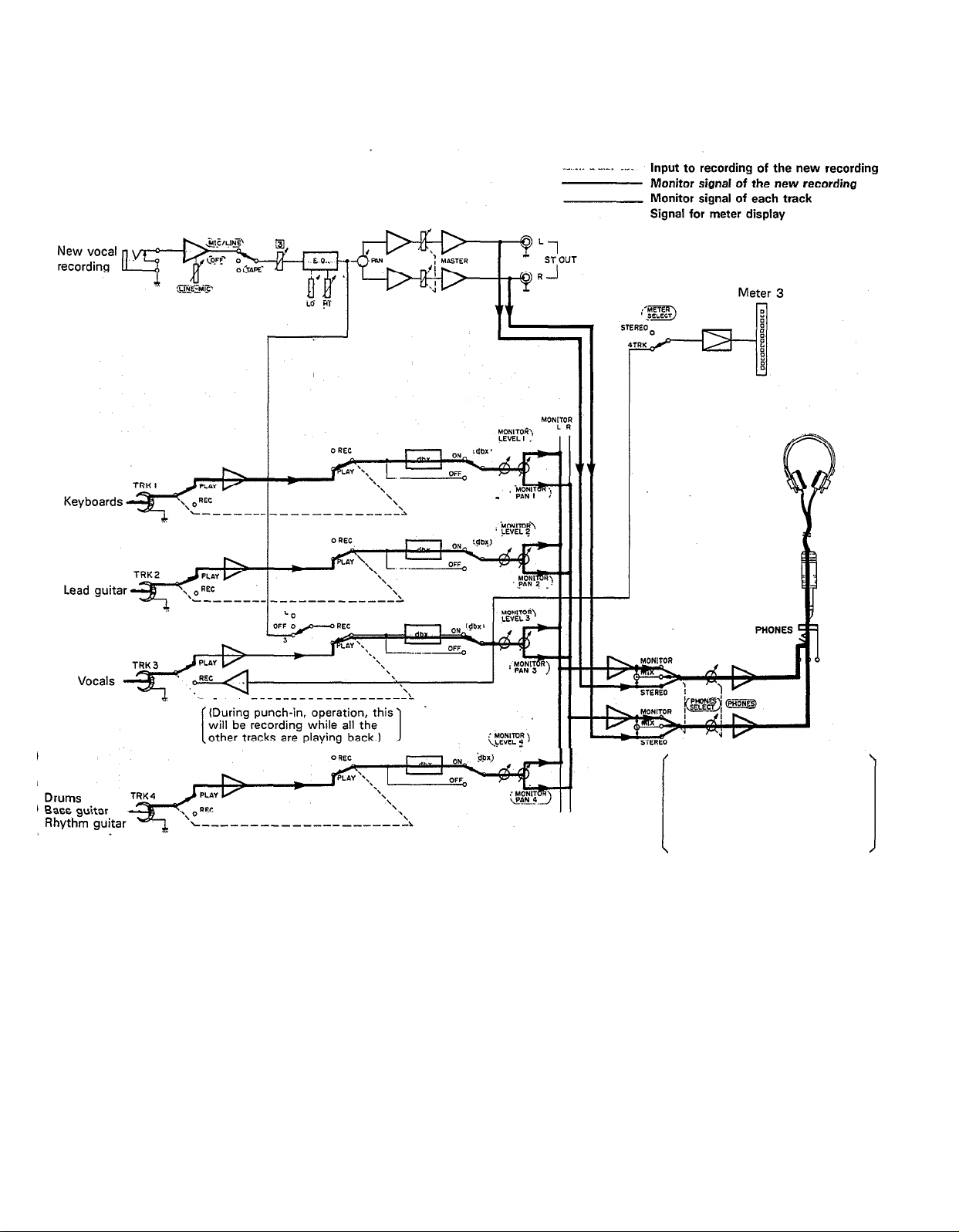
— Signal Path during Punch-in/Punch-out Operation —
Before and after the punch-in, the
sound from tracks 1-4 plus the
new sounds to be recorded can be
monitored. However, during the
punch-in, only the sound from
tracks 1, 2, and 4 plus the new
sound being recorded can be
monitored.
28
Page 31

—
Punch-in/Punch-out Procedure —
1. Connections
Connect the vocal microphone through input jack 3.
If the FS-1 Foot Switch is being used, connect it
to the PUNCH IN/OUT jack.
2. Setting the recorder
If the FS-1 Foot Switch is connected, set RECORD
SELECT switch 3 to the “3” position. The REC indicator will flash.
After pressing the PAUSE switch, press the REC
switch. (If the FS-1 is being used, the unit is put
into the REC PAUSE mode, and the REC indicator
lights.)
If the FS-1 is connected, set its foot switch so that
the REC indicator flashes.
29
3. Setting the monitor and meter sections
Set the PHONES SELECT switch to “MIX”. (If it’s
not set to this position, you won’t be able to monitor
the new recording sound and the playback sound
of tracks 1
operation.)
Turn the MONITOR LEVEL control to about “7”.
Turn the PHONES volume to about “7”.
Set the METER SELECT switch to “4 TRK”.
— 4 during punch-in/punch-out
Page 32

*Explanation diagram for steps to
4. Setting input levels
Set input select switch 3 to “MIC/LlNE”.
Set both input fader 3 and the MASTER fader to “7”.
Slide gain control 3 in the “MIC” direction, stop-
ping when the “+3” LED indicator on the. level
meter third from the left flashes occasionally on
music peaks. (Setting the same as when the vocals
were initially recorded is recommended.)
5. Adjusting the recording level and sound
characteristics
Using the equalizer controls for channel 3, adjust
for the desired sound characteristics. It’s a good
idea to set them where they were for the initial
recording.
After setting the equalization, set the recording
level, preferably at the same level as the initial
recording.
6. Recording
Press the PAUSE switch to start the recording.
“Punch-in” when you reach the passage that must
be redone by sliding the RECORD SELECT switch
to the “3” position. When using the FS-1, press on
the foot switch. In both cases, the REC indicator
will light.
“Punch-out” when you have finished redoing the
passage by sliding the RECORD SELECT switch to
the “OFF” position. When using the FS-1, press on
the foot switch again. In both cases, the REC indicator will begin flashing.
Rewind the tape.
— Punch-in/Punch-out Completed —
7. Post recording check
Press the PLAY switch to make sure the passage
was redone correctly.
Return all controls and switches to their normal
positions, and rewind the tape. We’re now ready for
mixdown recording.
30
Page 33

MIXDOWN (TRACKDOWN)
It’s now time for the mixdown. Often called “trackdown”
or “remix”, mixdown is when all the four recorded tracks
are mixed to achieve a certain sound’ balance in level,
effects, and stereo positioning, and then recorded onto
one side of a cassette tape in mono or stereo. This tape
is the final “master”.
— Signal Path During Mixdown —
In this next step, the instruments are “put in their place”
in the stereo sound field, and a slight amount of reverb
will be added to the vocal track with the REV7.
31
Page 34

— Mixdown Procedure —
1. Connections
Connect a stereo tape deck to the ST OUT jack, and
insert a blank tape to record the final mix in stereo.
Connect the REV7 Digital Reverberator through the
AUX SEND jack and AUX RETURN jacks.
2. Setting the meter and monitor sections
Set the PHONES SELECT switch to “STEREO” in
order to monitor the mixed down sound.
Turn the PHONES volume to about “7”.
Set the METER SELECT switch to “STEREO” so
that the level of the mixed down signal will be
indicated.
3. Adjust the level balance and sound characteristics
Set all the input select switches 1 — 4 to “TAPE”.
Press the PLAY switch to start the tape, and adjust
the level balance of each track. Push the MASTER
fader up to “7’: and then set the level balance with
each channel fader.
Adjust the sound characteristics for each track with
the equalizer controls for channels 1 — 4.
Add the effects to the vocal track using the AUX
3, AUX MASTER SEND, and AUX RTN controls.
*Explanation diagram for steps to and
Determine the stereo positioning of the instruments
recorded on each track using the PAN controls 1 —
4.
If necessary, repeat steps
everything sounds right.
Watching level meters 1 and 2, use the MASTER
fader to set the output level of the signal sent from
the ST OUT jacks.
Watching the level meters of the stereo tape deck,
set its proper recording level.
Rewind the tape.
4. Recording
Press the PLAY switch of the MT1X at the same
time you start recording with the stereo tape deck.
After the recording is finished, play back the mixed
down tape. How does it sound? You can keep repeating the mixdown process, varying the levels,
equalizations, and effect level balance until you’re
fully satisfied with the results. When you make that
“perfect” mix, congratulations. You’ve finished your
stereo master.
—
Mixdown Completed
—
through until
32
Page 35

SYNC-RECORDING
For synchronized operation with MIDI instruments, the
optional YMC10 MIDI converter enables synchrooperation of the CMX1 and MIDI instruments such as
the RX11, RX15, and RX21 digital rhythm programmers
and the QX1 and QX7 digital sequence recorders. In
this section, we will explain synchro-recording using
synchro-operation techniques.
Merits of synchro-recording
Synchro-recording enables the use of digital sources
such as rhythm programmers and sequencers during the first mixdown stages. Since these sources
are recorded directly onto the master, it extracts
the full sound quality, dynamic range, and superb
S/N performance of these digital instruments.
Operating the tape sync
In order to work the tape sync, the MIDI synchronizing signal must be converted to an FSK (frequency
shift keying) signal first. This is because MIDI
transmits information at an extremely high maximum
speed of 31.25 K baud per second.
Therefore, the use of analog instruments is impossi-
ble. By using the MIDI converter, the MIDI syn-
chronizing signal is converted to an FSK signal that
analog instruments can handle.
With the SYNC switch “ON”, press the PLAY
switch and the FSK signal recorded on track 1 is
sent to the YMC10, which converts it to the MIDI
synchronizing signal and outputs it to the RX15.
In this way, track 1 of the MT1X operates the
RX15. FOR THIS OPERATION, DON’T FORGET
TO SET THE RX15 SYNC SWITCH TO “MIDI”.
Now, tracks 2-4 can be used for overdubbing.
Connect as shown below for mixdown.
An example of synchro-recording using the
RX 15 rhythm programmer
Set the RX15 to create the desired rhythm
effects.
Connect the RX15 in the following manner.
After putting the MT1X into the REC PAUSE
mode, turn the SYNC switch “ON”. In this condition, both the tape will start and the RX15 will
start playing when the PAUSE switch is pressed.
Here’s how it works. The YMC 10 converts the
MIDI synchronizing signal from the RX15 to FSK
signal, which is recorded on track 1 of the MT1X.
In order to operate the RX15 by the FSK signal
recorded on track 1, connect everything like this:
Start the tape, mixdown the sound from tracks
2—4 and the RX15’s drum sounds input through
the AUX Left and Right jacks, and record it with
a stereo tape deck.
33
Page 36

EDITING VIDEO SOUNDTRACKS
Most people will agree that the sound recorded by the
video camera’s microphone just isn’t enough for a good
music video.
Using the MT1X to edit down a good soundtrack for
your video is a great idea, and will result in a video that
sounds surprisingly professional. You’ll find this capabili-
ty useful to produce a promotional video for your group.
In the following example, we’ll show you how to make
a soundtrack that includes the sound recorded by the
video camera’s microphone, narration, background
music, and sound effects.
Editing Procedure
Playback the video several times in order to create
a good, tight scenario. If you’re going to edit the
video footage, do it first.
Use track 1 to record the sound recorded by the
video camera’s microphone.
Track 2 is for recording the narration. While watching
the video and monitoring track 1 with headphones,
record the narration with a microphone.
Overdub the background music on track 3. If this
music is in stereo, use tracks 3 and 4. If it’s just
mono, track 3 will suffice.
Sound effects can be recorded on track 4.
Mix down the sound from tracks 1-4 and record
them on the video soundtrack using the video decks
overdubbing function.
NOTE: This example is when editing the soundtrack of
a monaural video deck with an overdubbing
function.
MAINTENANCE
As a good general rule, the tape heads, pinchroller and
capstan should be cleaned before each recording, thus
ensuring the best audio quality.
After the deck has been used for a period of time, the
heads, pinchroller, and capstan will become dirty. This
increases noise and uneven rotation, leading to a
deterioration in sound quality. Therefore, periodic cleaning and demagnetization is a must to preserve optimal
audio performance.
Use cotton swabs and alcohol or head cleaning fluid
(available in most all audio stores) to clean the heads,
capstan, and pinchroller. Keeping the heads clean is
essential for good recordings. For demagnetization, use
a quality head demagnetizer, and follow the instructions
carefully.
It’s important to keep all parts clean!
34
Page 37

BLOCK DIAGRAM
NOTE:
When the REC button is engaged, the panel switches can be used to individually order
recording on only those channels with RECORD SELECT not switched “OFF”.
35
Page 38

SPEC IFIC ATIO NS
Model Description : multitrack cassette recorder
Mechanical Descriptions
Tape
Heads
Tape speed
Pitch control
Wow & flutter
Fast forward/rewind time
Motor
Inputs & Outputs
INPUT 1—4
AUX RTN L/R
ST OUT L/R
AUX SEND
TAPE OUT 1—4
PHONES
: standard cassette; CrO2 tape only (EQ: 70µs)
: hard permalloy 4-channel rec/play head
ferrite 4-channel erase head
: 4.75 cm/sec
: +/-10%
: 0.05% WRMS
: about 100 seconds (C-60 tape)
: DC servo
input impedance
rated input level
minimum input level
maximum input level
input impedance
rated input level
output impedance
rated impedance load
rated output level
output impedance
rated impedance load
rated output level
output impedance
rated impedance load
rated output level
rated impedance load
maximum output level
: 10k ohms
: - 10dB to - 50dB (input fader in specified position)
:
- 56dB (gain control MAX, input fader MAX)
: + 10dB (gain control MIN, headroom margin)
: 10k ohms
: -10dB
: 1k ohms
: 10k ohms or over
: - 10dB (at 50k ohms)
: 1k ohms
: 10k ohms or over
: - 10dB (at 50k ohms)
: 1k ohms
: 10k ohms or over
: - 10dB (at 50k ohms)
: 8-40 ohms
:
100mW + 100mW
Equalizer Characteristics
Sound Specifications
Total frequency response
Total signal to noise ratio
Total distortion
Channel separation
Erasure ratio
General
Power supply
Power consumption
Dimensions (W x H x D)
Weight
Supplied accessories
0dB=0.775Vr.m.s.
Specifications subject to change without notice.
HIGH
LOW
: 40Hz—12.5kHz, +/- 3dB
: 85dB (dbx ON, IHF-A)
: less than 1% (EIAJ, 315Hz)
: better than 55dB (1 kHz)
: better than 70dB
: supplied AC adaptor (DC 15V), PA11 battery pack (“C” x 10)
: 14w
: 365mm x 26mm x 225mm (14-1/3” x 2-1/2” x 8-7/8”)
: 2.5 kg (5.5 Ibs)
: carrying strap, PA10 AC adaptor
: +/- 10dB (10kHz shelving)
: +/- 10dB (100Hz shelving)
36
Page 39

INTRODUCTION TO THE ACCESSORIES
37
Page 40

The MTlX is supported by Yamaha’s worldwide network of
factory trained and qualified dealer service personnel. In the event
of a problem, contact your nearest Yamaha dealer.
SERVICE
Page 41

SINCE 1887
NIPPON GAKKI CO., LTD. HAMAMATSU, JAPAN
Page 42

YAMAHA
Yamaha Corporation of America
6600 Orangethorpe Avenue, P.O. Box 6600, Buena Park, CA 90622-6600
5/15/98 28791
MT1X OM
®
Recyclable
MT1X OM
Recycled
Page 43

documentation manual, user maintenance, brochure, user reference, pdf manual
This file has been downloaded from:
User Manual and User Guide for many equipments like mobile phones, photo cameras, monther board, monitors, software, tv, dvd, and othes..
Manual users, user manuals, user guide manual, owners manual, instruction manual, manual owner, manual owner's, manual guide,
manual operation, operating manual, user's manual, operating instructions, manual operators, manual operator, manual product,
 Loading...