

Yamaha Audio MSP10M, MSP10 User Manual
MONITOR SPEAKER
MSP10
MSP10M
Owner’s manual
Mode d’emploi
Bedienungsanleitung
Manual de instrucciones
M

3
Thank you for purchasing the Yamaha MSP10/10M monitor speaker system. The
MSP10/10M features a compact bass reflex cabinet, with a 20 cm two-way cone
speaker and a 2.5 cm titanium dome speaker. This powered bi-amplifier speaker
system faithfully reproduces sound and can be used for a wide range of applications,
from personal home recordings to serious professional use. Please read this Owner’s
Manual thoroughly to make the best use of the MSP10/10M’s quality functions for the
longest period of time, and keep the manual in a safe place.
Precautions
Warnings
• Do not allow water to enter this unit or allow the
unit to become wet. Fire or electrical shock may
result.
• Connect this unit’s power cord only to an AC outlet
of the type stated in this Owner’s Manual or as
marked on the unit. Failure to do so is a fire and
electrical shock hazard.
• Do not scratch, bend, twist, pull, or heat the power
cord. A damaged power cord is a fire and electrical
shock hazard.
• Do not place heavy objects, including this unit, on
top of the power cord. A damaged power cord is a
fire and electrical shock hazard. In particular, be
careful not to place heavy objects on a power cord
covered by a carpet.
• If you notice any abnormality, such as smoke, odor,
or noise, or if a foreign object or liquid gets inside
the unit, turn it off immediately. Remove the power
cord from the AC outlet. Consult your dealer for
repair. Using the unit in this condition is a fire and
electrical shock hazard.
• Should this unit be dropped or the cabinet be
damaged, turn the power switch off, remove the
power plug from the AC outlet, and contact your
dealer. If you continue using the unit without
heeding this instruction, fire or electrical shock may
result.
• If the power cord is damaged (i.e., cut or a bare
wire is exposed), ask your dealer for a replacement.
Using the unit with a damaged power cord is a fire
and electrical shock hazard.
• Do not remove the unit’s cover. You could receive
an electrical shock. If you think internal inspection,
maintenance, or repair is necessary, contact your
dealer.
• Do not modify the unit. Doing so is a fire and
electrical shock hazard.
Cautions
• When rack-mounting the unit, allow enough free
space around the unit for normal ventilation. This
should be: 10 cm at the sides, 30 cm behind, and
60 cm above.
For normal ventilation during use, remove the rear
of the rack or open a ventilation hole.
If the airflow is not adequate, the unit will heat up
inside and may cause a fire.
• This unit has ventilation holes at the rear to prevent
the internal temperature rising too high. Do not
block this. Blocked ventilation holes are a fire
hazard.
• This unit is heavy. Use two or more people to carry
it.
• Keep this unit away from the following locations:
—Locations exposed to oil splashes or steam, such
as near cooking stoves, humidifiers, etc.
—Unstable surfaces, such as a wobbly table or
slope.
—Locations exposed to excessive heat, such as
inside a car with all the windows closed, or
places that receive direct sunlight.
—Locations subject to excessive humidity or dust
accumulation.
• Hold the power cord plug when disconnecting it
from an AC outlet. Never pull the cord. A damaged
power cord is a potential fire and electrical shock
hazard.
• Do not touch the power plug with wet hands.
Doing so is a potential electrical shock hazard.
4
Operating Notes
• Turn off all musical instruments, audio equipment,
and speakers when connecting to this unit. Use the
correct connecting cables and connect as specified.
• Always lower the volume control to minimum
before turning on the power to this unit. A sudden
blast of sound may damage your hearing.
• Do not raise the volume of headphones or speakers
to a level that makes you feel uncomfortable.
Listening to loud music for long periods can
damage your hearing.
• This speaker is magnetic shielded. However, if a
nearby monitor displays any uneven colors, place it
further away from the monitor.
• You may feel a flow of air in and out of the port on
this unit. This is not abnormal and sometimes
occurs when a program with a lot of bass range is
played.
• XLR-type connectors are wired as follows: pin 1:
ground, pin 2: hot (+), and pin 3: cold (–).
WARNING: THIS APPARATUS MUST BE EARTHED
IMPORTANT
THE WIRES IN THIS MAINS LEAD ARE COLOURED IN
ACCORDANCE WITH THE FOLLOWING CODE:
GREEN-AND-YELLOW : EARTH
BLUE : NEUTRAL
BROWN : LIVE
As the colours of the wires in the mains lead of this apparatus may
not correspond with the coloured markings identifying the terminals in
your plug, proceed as follows:
The wire which is coloured GREEN and YELLOW must be
connected to the terminal in the plug which is marked by the letter E
or by the safety earth symbol or coloured GREEN and YELLOW.
The wire which is coloured BLUE must be connected to the terminal
which is marked with the letter N or coloured BLACK.
The wire which is coloured BROWN must be connected to the
terminal which is marked with the letter L or coloured RED.
* This applies only to products distributed by YAMAHA KEMBLE
MUSIC (U.K.) LTD.
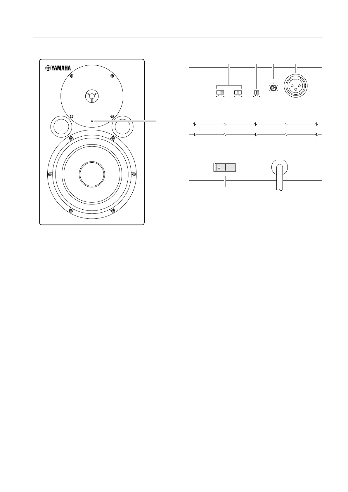
Front panel/Rear panel
1
Power/Clip indicator
This indicator lights up green when you turn the
POWER switch on the rear panel ON. If the output
level is too high, causing clipping at the amplifier,
the indicator lights up red. In this case, lower the
input level.
1
2 3 5
–2 –1
0 –1 ON0
LOW
ON OFF
POWER
HIGH (80Hz)
TRIM
+1 OFF
LOW CUT
4
+4dB
MIN –6dB
SENSITIVITY INPUT
6
2
TRIM switches
These switches enable you to adjust the bass and
treble for the MSP10/10M.
LOW: three positions
The LOW switch adjusts the bass range. With the
“–1” and “–2” settings, the bass range is cut by
1.5 dB when based on a reference value of 50 Hz
with the “0” setting.
HIGH: three positions
The HIGH switch adjusts the treble. With the “+1”
setting, the treble range is boosted by 1.5 dB when
based on a reference value of 10 kHz with the “0”
setting. With “–1” setting, the treble range is cut by
1.5 dB.
3
LOW CUT switch
This switch turns on or off the high-pass filter that
cuts frequency ranges below 80 Hz.
4
SENSITIVITY control
Adjust the volume according to the output
sensitivity of the connected device.
(The factory default setting is “MIN.”)
INPUT jack
5
This is an XLR-type balanced input jack.
6
POWER switch
This switch turns the power to the MSP10/10M on
and off. When you turn this switch on, the power/
clip indicator lights up green.
5
Specifications
General specifications
Type........................................... Amplified 2Way Bass Reflex Powered Speaker (Bi-Amp.)
Crossover Frequency .................. 2.0 kHz, 30 dB/oct
Frequency Range ....................... 40 Hz to 40 kHz (–10 dB)
Sensitivity ..................................–10 dB at –6 dB position (for 100 dB/SPL, 1 m on Axis)
Maximum Output Level............. 110 dB (1 m on Axis)
Dimensiones (W
Weight.......................................20 kg
Speaker unit
Speaker Unit.............................. LF: 20 cm Cone (4
Enclosure................................... Type: Bass Reflex
Amp.unit
Maximum Output Power............LF: 120 W at 400 Hz, THD= 0.02%, RL= 4
Input Sensitivity/Impedance ....... –6 dB to +4 dB/10 k
Hum & Noise.............................
Signal to Noise Ratio..................
Controls..................................... TRIM Switch
Connectors ...............................Input XLR-3-31
Power Indicator/Clip Indicator ... Green/Red LED
Power Requirement....................USA and Canada: AC 120 V, 60 Hz
Power Consumption...................150 W
Option....................................... Wall mounting bracket BWS251-300
×
H
×
D).......... 265
×
420
×
329 mm
Ω
, magnetic shielded)
HF: 2.5 cm Titan Dome (8
HF: 60 W at 10 kHz, THD= 0.02%, RL= 8
≤
–67 dBu (Volume= Min) DIN Audio filter
≥
98 dB (IEC-A Weighting)
LOW: 3 positions (0 dB, –1.5 dB, –3 dB at 50 Hz)
HIGH: 3 positions (+1.5 dB, 0 dB, –1.5 dB at 10 kHz)
LOW CUT Switch: ON/OFF
SENSITIVITY Control
POWER Switch: ON/OFF
Europe: AC 230 V, 50 Hz
Others: AC 240 V, 50 Hz
Ω
, magnetic shielded)
Ω
Ω
Ω
Specifications and appearance are subject to change without notice.
For European Model
Purchaser/User Information specified in EN55103-1 and EN55103-2.
Inrush Current: 11A
Conformed Environment: E1, E2, E3 and E4
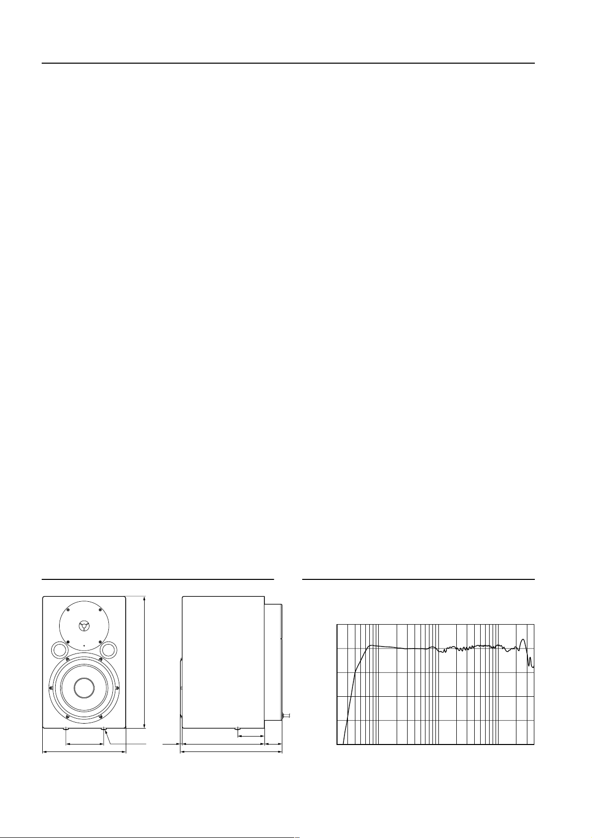
Dimensions
Performance graph
Standard frequency response
+10
0
120
W: 265
2-M8 Screws
H: 420
2625.5
D: 329
85
61.5
Unit: mm
–10
–20
RESPONSE (dB)
–30
–40
20
10k1k100
FREQUENCY (Hz)
6
Block Diagram
HPF
TRIM
EQ
+1
0
–1
HIGHLOW
LPF
INPUT
HPF
LOW CUTSENSITIVITY
0
–1
–2
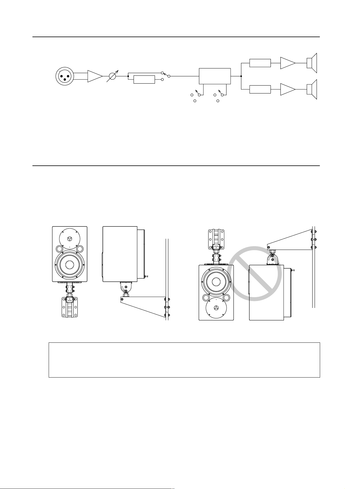
Mounting the MSP10/10M on the wall
You can install the MSP10/10M on the wall using an optional Yamaha wall bracket BWS251-300. For more
information on how to install it, refer to the instructions that come with the wall bracket. For the angle and
position of installation, refer to the figure below.
The wall should be strong enough to support the speaker and equivalent to a sheet of plywood with a
thickness of 18 mm (11/16 inches) or more. Use appropriate tools for installation.
• Recommend for new constructions.
• Ask an installation specialist for instruction.
• Some installation parts may deteriorate due to friction or corrosion over a long period of time. For safety,
check these parts and condition regularly.
7

MSP10/10M Mode d’emploi
Nous vous remercions d’avoir opté pour le système d’enceinte d’écoute MSP10/10M
de Yamaha. Le système MSP10/10M dispose d’un coffret bass reflex compact avec un
haut-parleur deux voies en cône de 20 cm et un haut-parleur avec un dôme en titane
de 2,5 cm. Ce système d’enceinte active biamplifiée reproduit le son avec fidélité et
peut avoir de nombreuses applications allant de l’enregistrement à domicile à un
usage professionnel intensif. Veuillez lire attentivement ce Mode d’emploi afin de
tirer le meilleur parti des qualités du MSP10/10M durant de longues années.
Conservez ensuite ce mode d’emploi dans un endroit sûr.
Précautions
Avertissements
• Evitez de mouiller l’appareil. Il y a risque
d’incendie ou d’électrocution.
• Ne branchez le cordon d’alimentation de cet
appareil qu’à une prise secteur qui répond aux
caractéristiques données dans ce manuel ou sur
l’appareil, faute de quoi, il y a risque d’incendie.
• Evitez de griffer, tordre, plier, tirer ou chauffer le
cordon d’alimentation. Un cordon d’alimentation
endommagé constitue un risque d’incendie ou
d’électrocution.
• Ne posez pas d’objets pesants (à commencer par
l’appareil lui-même) sur le cordon d’alimentation.
Un cordon d’alimentation endommagé peut
provoquer un incendie ou une électrocution. Cette
précaution est notamment valable lorsque le
cordon d’alimentation passe sous un tapis.
• Si vous remarquez un phénomène anormal tel que
de la fumée, une odeur bizarre ou un
bourdonnement ou, encore, si vous avez renversé
du liquide ou des petits objets à l’intérieur, mettez
l’appareil immédiatement hors tension et
débranchez le cordon d’alimentation. Consultez
votre revendeur pour faire examiner l’appareil.
L’utilisation de l’appareil dans ces conditions
constitue un risque d’incendie ou d’électrocution.
• Lorsque l’appareil tombe ou si le boîtier est
endommagé, coupez l’alimentation, débranchez le
cordon de la prise secteur et contactez votre
revendeur. L’utilisation de l’appareil dans ces
conditions constitue un risque d’incendie ou
d’électrocution.
• Si le cordon d’alimentation est endommagé (s’il est
coupé ou si un fil est à nu), veuillez en demander
un nouveau à votre revendeur. L’utilisation de
l’appareil avec un cordon d’alimentation
endommagé constitue un risque d’incendie ou
d’électrocution.
• N’ouvrez jamais le boîtier de cet appareil. Il y a
risque d’électrocution. Si vous pensez que
l’appareil doit subir une révision, un entretien ou
une réparation, veuillez contacter votre revendeur.
• Cet appareil ne peut pas être modifié par
l’utilisateur. Il y a risque d’incendie ou
d’électrocution.
8
 Loading...