

Yamaha Audio MS400 User Manual
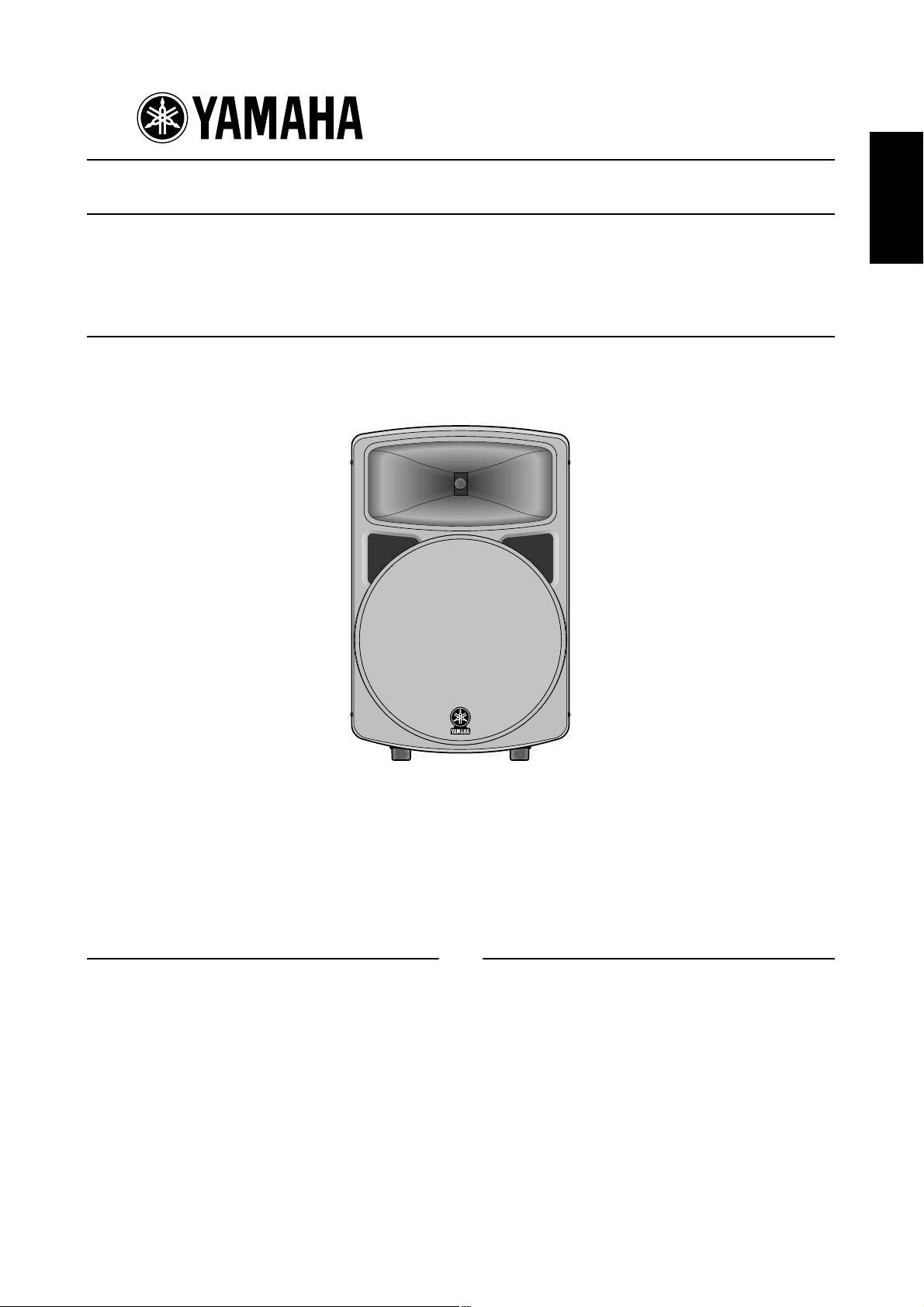
POWERED SPEAKER
ENGLISH
MS400
Owner’s Manual
Mode d’emploi
Bedienungsanleitung
Manual del Usuario
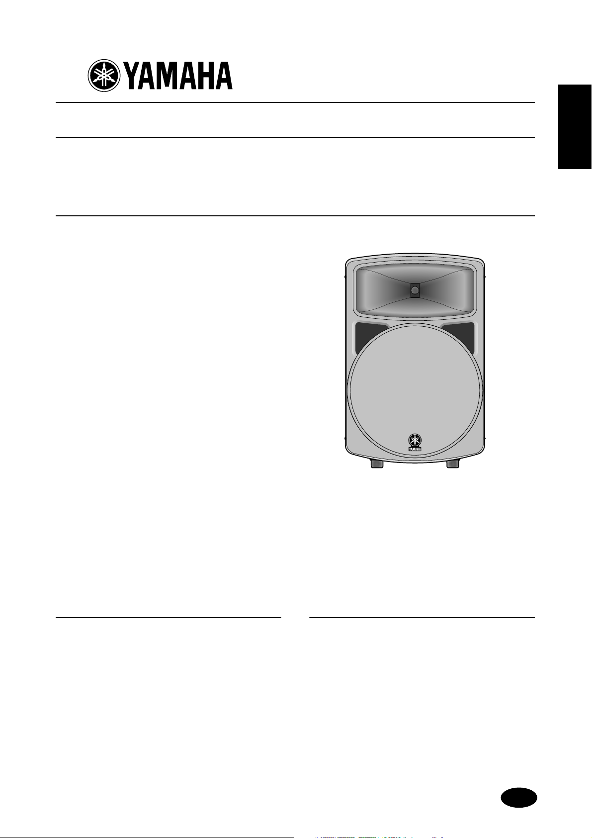
Thank you for purchasing the Yamaha MS400 powered speaker system.
The development of this powered bi-amplifier speaker system is a natural extension of
Yamaha’s extensive experience and knowledge of PA devices. The MS400 faithfully reproduces sound for a wide range of applications. Please read this owner’s manual thoroughly
to make the best use of the MS400 for the longest possible period of time. Keep the manual
in a safe place for future reference.
Features
• Lightweight, high-powered speaker with a
newly-developed 15-inch neodymium magnet
woofer
• The speaker uses an “EE Engine” based on
Yamaha’s proprietary amplifier drive technology
for high-efficiency drive. It features a high-output
bi-amplifier configuration (LF 300 W and HF
100 W).
• Optional speaker stand and installation brackets
available for various applications.
Contents
Precautions............................................................... 2
Rear Panel................................................................. 3
Connection Examples.............................................. 4
Specifications............................................................ 5
General specifications ..............................................5
Amp.unit ..................................................................5
Dimensions .............................................................. 5
Performance graph .................................................. 5
Block Diagram.......................................................... 5
Installation Examples............................................... 6
M

Precautions
• Do not allow water to enter this unit or allow the unit
to become wet. Fire or electrical shock may result.
• Do not place a container with liquid or small metal
objects on top of this unit. Liquid or metal objects
inside this unit are a fire and electrical shock hazard.
• Connect the included power cord only to an AC
outlet of the type stated in this Owner’s Manual or
as marked on the unit. Failure to do so is a fire and
electrical shock hazard.
• Do not scratch, bend, twist, pull, or heat the power
cord. A damaged power cord is a fire and electrical
shock hazard.
• Do not place heavy objects, including this unit, on
top of the power cord. A damaged power cord is a
fire and electrical shock hazard. In particular, be
careful not to place heavy objects on a power cord
covered by a carpet.
• Place the device near a power outlet so you can easily plug it in.
• If you notice any abnormality, such as smoke, odor,
or noise, or if a foreign object or liquid gets inside
the unit, turn it off immediately. Remove the power
cord from the AC outlet. Consult your dealer for
repair. Using the unit in this condition is a fire and
electrical shock hazard.
• Should this unit be dropped or the cabinet be damaged, turn the power switch off, remove the power
plug from the AC outlet, and contact your dealer. If
you continue using the unit without heeding this
instruction, fire or electrical shock may result.
• Use only the included power cord for this unit.
Using other types may be a fire and electrical shock
hazard.
• The power to this device is not completely shut off
even when the power switch is turned off. Locate the
device close to the AC outlet so you can easily reach
the power plug.
• If the power cord is damaged (i.e., cut or a bare wire
is exposed), ask your dealer for a replacement.
Using the unit with a damaged power cord is a fire
and electrical shock hazard.
• Do not remove the unit’s cover. You could receive an
electrical shock. If you think internal inspection,
maintenance, or repair is necessary, contact your
dealer.
• Do not modify the unit. Doing so is a fire and electrical shock hazard.
• Turn off all audio equipment, and speakers when
connecting to this unit. Use the correct connecting
cables and connect as specified.
• Always lower the volume control to minimum
before turning on the power to this unit. A sudden
blast of sound may damage your hearing.
• Allow enough free space around the unit for normal
ventilation. This should be: 20 cm at the sides, 25
cm behind, and 30 cm above.
For normal ventilation during use, remove the rear
of the rack or open a ventilation hole.
If the airflow is not adequate, the unit will heat up
inside and may cause a fire.
• This unit is heavy. Use two or more people to carry
it.
• If you stack the speakers, secure the handles of the
speakers using a belt and fix the speakers to the floor
or wall to prevent them from falling and causing
injury. Do not stack more than two speakers.
• Do not use the handles to suspend the speaker. Otherwise, it may fall, causing injury.
• Hold the power cord plug when disconnecting it
from an AC outlet. Never pull the cord. A damaged
power cord is a potential fire and electrical shock
hazard.
• Do not touch the power plug with wet hands. Doing
so is a potential electrical shock hazard.
• XLR-type connectors are wired as follows: pin 1:
ground, pin 2: hot (+), and pin 3: cold (–).
• Using a mobile telephone near this unit may induce
noise. If noise occurs, use the telephone away from
the unit.
• Do not use the speakers at uncomfortably loud
level. Otherwise, you may damage your hearing.
• If lightning begins to occur, turn off the power
switch of the unit as soon as possible, and unplug
the power cable plug from the electrical outlet.
• If there is a possibility of lightning, do not touch the
power cable plug if it is still connected. Doing so
may be an electrical shock hazard.
WARNING: THIS APPARATUS MUST BE EARTHED
IMPORTANT
THE WIRES IN THIS MAINS LEAD ARE COLOURED IN
ACCORDANCE WITH THE FOLLOWING CODE:
GREEN-AND-YELLOW : EARTH
BLUE : NEUTRAL
BROWN : LIVE
As the colours of the wires in the mains lead of this apparatus may
not correspond with the coloured markings identifying the terminals in
your plug, proceed as follows:
The wire which is coloured GREEN and YELLOW must be
connected to the terminal in the plug which is marked by the letter E
or by the safety earth symbol or coloured GREEN and YELLOW.
The wire which is coloured BLUE must be connected to the terminal
which is marked with the letter N or coloured BLACK.
The wire which is coloured BROWN must be connected to the
terminal which is marked with the letter L or coloured RED.
* This applies only to products distributed by YAMAHA KEMBLE
MUSIC (U.K.) LTD.
2
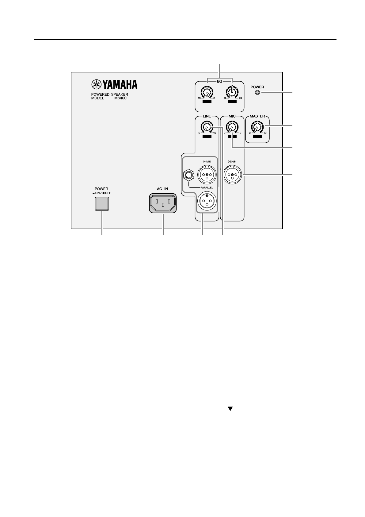
Rear Panel
9
8
LOW
HIGH
7
LEVEL LEVEL LEVEL
6
1
A
POWER switch
This switch turns the power to the MS400 on and
off. When you turn this switch on, the POWER
8
indicator (
B
AC IN connector
Connect the included power cord here.
C
LINE connectors
These balanced connectors accept input from
line-level sources, such as a mixer. The connectors include: an XLR-3-31 type; an XLR-3-32
type; a 1/4" TRS phone jack. They are all connected in parallel and can be used as line outputs.
In this case, input signals from the MIC connector (
5
D
LINE LEVEL control
This control enables you to adjust the level of signal input from the LINE connectors (
E
MIC connector
Mic-level sources are input at this balanced,
XLR-3-31 type connector. The internal low-cut
filter will cut the range of these signals below
70 Hz. The mic input will not be routed to any
destination other than the speaker.
) lights up green.
) will not be output.
3
132
231
2
).
3
F
MIC control
This control enables you to adjust the level of signal input at the MIC connector (
G
MASTER LEVEL control
This control enables you to adjust the entire volume level.
H
POWER indicator
When you turn the power on, this indicator lights
up green.
I
EQ control
LOW:
of 0 ~ –10 dB with a center frequency of 55 Hz.
The 0 (MAX) setting is flat. Turn the control
couterclockwise to cut.
HIGH:
setting is flat. Turn the control clockwise to
boost and couterclockwise to cut the HF band
(1.6 kHz or higher) in the range of ±3 dB.
132
5
4
).
5
This EQ adjusts the low band in the range
This EQ adjusts the high band. The arrow
3
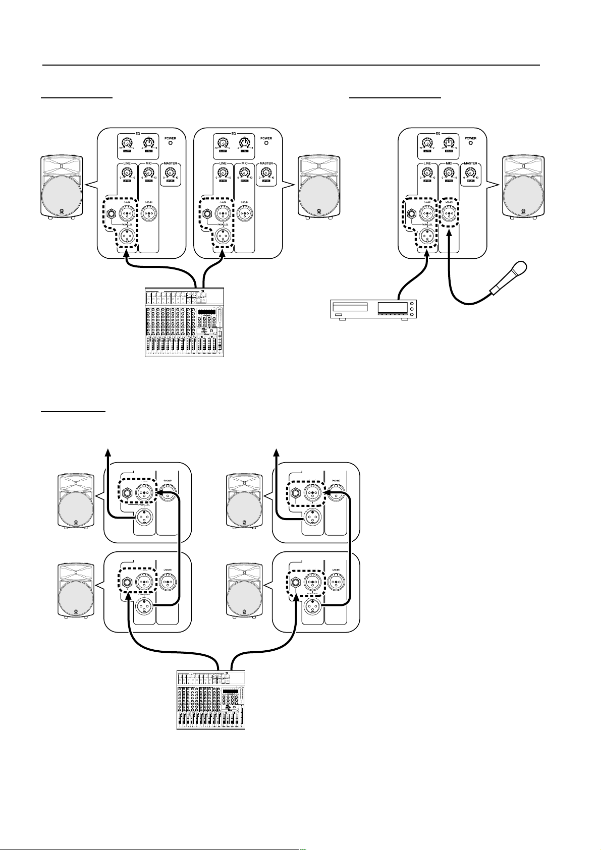
Connection Examples
Stereo setup Without a mixer
132
132 132
132 132
132
Daisy chain
To the next speaker
231
LINE OUT
Mixer
132
132
231
231
231
Microphone
CD player or tape deck
To the next speaker
132
132
231
132
132
231
LINE OUT
Mixer
4
132
132
231
Specifications
■
General specifications
Type
Bi-Amp 2-way bass reflex powered speaker
(Bi-amplifier electronic crossover network))
Speaker unit
LF : 38 cm cone
HF: 5 cm Titanium diaphragm compression driver
Frequency Range.................. 50 Hz~16 kHz (–10 dB)
Maximum Output Level.......... 124.5 dB (1m on Axis)
Directional angle.................... 90˚ (H)/40˚ (V)
Dimension (W x H x D).......... 449 x 683 x 379 mm
Weight ................................... 24.2 kg
Color...................................... Black (approx. Munsell value:
5PB 2/1)
Tripod pole diameter.............. 35~36 mm
Accessories.............................. Power cord (A C inlet type , 2.5 m)
■
Amp.unit
Maximum Output Power
LF: 300 W at 500 Hz, THD=1%, RL=4 Ω
HF:100 W at 5 kHz, THD=1%, RL=16 Ω
Crossover frequency ............. 1.6 kHz (30 dB/oct.)
Input Sensitivity ..................... LINE: +4 dB*, MIC: –50 dB*
Input impedance.................... LINE: 30 k Ω , MIC: 5 k Ω
Controls
LEVEL............... LINE, MIC, MASTER
EQ........................LOW: 0 (Max.) ~ –10 dB (Min.) at 55 Hz
HIGH: ±3 dB (HF)
Power switch.......................... On/Off
Connectors (all balanced):
LINE in/out........................XLR-3-31, XLR-3-32, phone
(They are all connected in parallel
and can be used as line outputs.)
MIC in............................ XLR-3-31
POWER indicator................... Green LED
Power Requirement USA and Canada.......120 V, 60 Hz
Europe........................230 V, 50 Hz
Others ........................240 V, 50 Hz
Power Consumption.............. 120 W
Accessories
* 0 dB=0.775 V
• Specifications and appearance are subject to change without
notice.
For European Model
Purchaser/User Information specified in EN55103-1 and
EN55103-2.
Inrush Current: 25A
Conformed Environment: E1, E2, E3 and E4
...................................Bracket adapter BAD251 (for
BWS251-400, BCS251, and BBS251)
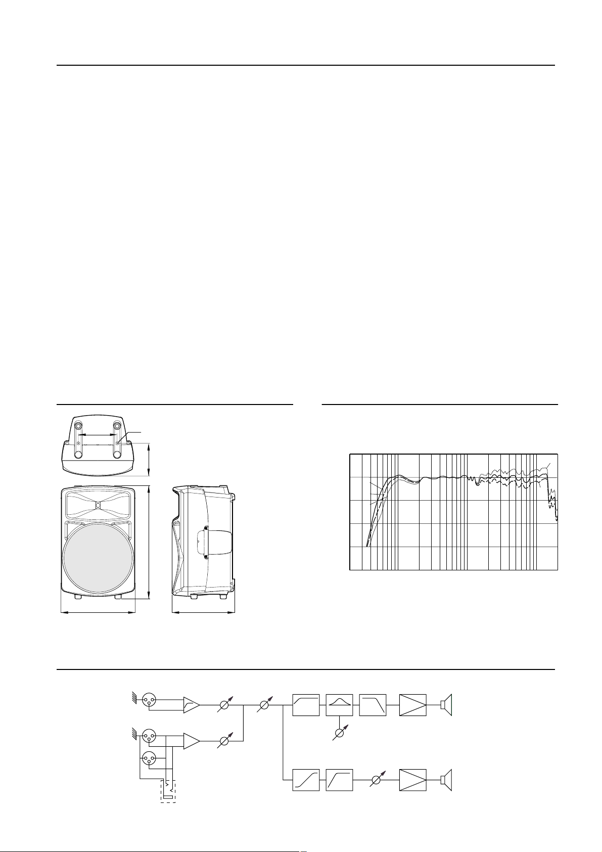
Dimensions
Remove the cover when you
M8
241
449
use optional brackets
203
683
Block Diagram
Mic Input
HPF
379
Mic
Unit: mm
Master
Performance graph
Standard Frequency Response
+10
0
0
–5
–10
–10
–20
RESPONSE (dB)
–30
–40
20
FREQUENCY (Hz)
LOW CUT P.AMP
LPF
+3
0
-3
10k1k100
LF
Line Input/Output
Phone Jack
Line
Freq. response
compensation
LOW
EQ
HPF
HIGH
EQ
SPEAKER
P.AMP
HF
SPEAKER
5
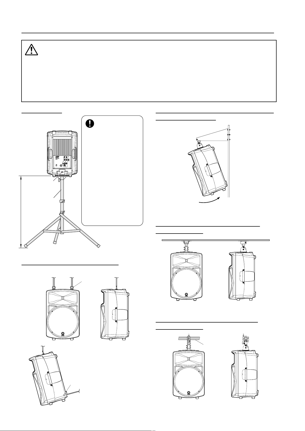
Installation Examples
• Installation must be carried out by an installation specialist.
• Do not install two or more speakers on a single speaker stand or bracket. The speaker(s) may
fall, resulting in injury.
• You need a BAD251 bracket adapter to use a BWS251-400, BCS251, or BBS251 speaker
bracket.
• Due to abrasion or corrosion, parts may deteriorate. To use the product safely, be sure to perform regular maintenance and inspections.
• Read the instruction manual for the speaker stand or speaker bracket when you install the
stand or bracket.
Speaker stand
Knob
Speaker stand
160 cm or less
BWS251-400 suspended speaker bracket
• Make sure the stand is
sufficiently durable to
support the weight of
the speaker.
• Set up the speaker
stand so that the height
will be 160 cm or less. If
the height exceeds
160 cm, the stand will
NEUTRIK
NEUTRIK
132
132
NEUTRIK
3
12
become unstable and
may fall.
• Place it on a level,
non-slippery, sturdy
surface.
• Spread the legs of the
stand to the maximum
extent.
• Be sure to fix the stand
so that it will not fall. (F or
example, you could
place a sand bag on the
tripod legs to add weight
for stability.)
and BAD251 adapter
max. 20 degrees
BCS251 ceiling speaker bracket and
BAD251 adapter
235923
Ceiling suspending with eye bolts
* M8 eye bolts are optional.
M8 eye bolt
• You can tilt or incline the speaker
using a knob (eye bolt M6).
Knob (eye bolt M6)
BBS251 baton speaker bracket and
BAD251 adapter
Baton diameter
ø34 –ø51
235923
6
Enceinte active
FRANÇAIS
MS400
Mode d’emploi
Nous vous remercions d’avoir opté pour le système d’enceinte active MS400.
La conception de cette enceinte active à double amplificateur est le fruit de la longue expérience et du savoir-faire de Yamaha dans le domaine de la sonorisation. Veuillez lire complètement ce mode d’emploi afin d’exploiter au mieux et le plus longtemps possible votre
MS400. Conservez le mode d’emploi dans un endroit sûr pour toute référence ultérieure.
Caractéristiques
• Enceinte légère, de haute puissance, dotée d’un
woofer à aimant néodyme 15 pouces.
• L’enceinte se sert d’un moteur “EE Engine” basé
sur la technologie développée par Yamaha pour les
amplificateurs d’excitation. Il a une configuration
à double amplificateur de haute puissance (grave
300W et aigu 100W).
• Un pied et des fixations sont disponibles en option
pour placer les enceintes en fonction de diverses
applications.
Sommaire
Précautions............................................................... 8
Face arrière ............................................................... 9
Exemples de connexion ......................................... 10
Fiche technique ...................................................... 11
Caractéristiques générales .....................................11
Amplification .........................................................11
Dimensions ............................................................ 11
Graphique............................................................... 11
Schéma.................................................................... 11
Exemples d’installation.......................................... 12

Précautions
• Evitez de mouiller l’appareil ou de laisser pénétrer
de l’eau dans son boîtier. Il y a risque d’incendie ou
d’électrocution.
• Ne posez pas de récipient contenant des liquides ou
de petits objets métalliques sur l’appareil. Si un
liquide ou des objets métalliques pénètrent dans
l’appareil, il y a risque d’incendie ou d’électrocution.
• Ne branchez le cordon d’alimentation fourni qu’à
une prise secteur qui répond aux caractéristiques
données dans ce manuel ou sur l’appareil, faute de
quoi, il y a risque d’incendie.
• Evitez de griffer, tordre, plier, tirer ou chauffer le
cordon d’alimentation. Un cordon d’alimentation
endommagé constitue un risque d’incendie ou
d’électrocution.
• Ne posez pas d’objets pesants (à commencer par
l’appareil lui-même) sur le cordon d’alimentation.
Un cordon d’alimentation endommagé peut provoquer un incendie ou une électrocution. Cette précaution est notamment valable lorsque le cordon
d’alimentation passe sous un tapis.
• Veillez à placer l’unité en proximité d’une prise
murale afin de pouvoir la connecter sans problème.
• Si vous remarquez un phénomène anormal tel que
de la fumée, une odeur bizarre ou un bourdonnement ou, encore, si vous avez renversé du liquide ou
des petits objets à l’intérieur, mettez l’appareil
immédiatement hors tension et débranchez le cordon d’alimentation. Consultez votre revendeur
pour faire examiner l’appareil. L’utilisation de
l’appareil dans ces conditions constitue un risque
d’incendie ou d’électrocution.
• Si cet appareil tombe ou si le boîtier est endommagé, coupez l’alimentation, débranchez le cordon
de la prise secteur et contactez votre revendeur.
L’utilisation de cet appareil dans ces conditions
constitue un risque d’incendie ou d’électrocution.
• Utilisez uniquement le câble d’alimentation fourni.
Le recours à tout autre type risque de provoquer une
électrocution.
• Même lors de la coupure avec le commutateur secteur, le dispositif reste en fait sous tension. En cas de
besoin, il convient dès lors de déconnecter le cordon
d’alimentation s’il vous y avez facilement accès.
• Si le cordon d’alimentation est endommagé (s’il est
coupé ou si un fil est à nu), veuillez en demander un
nouveau à votre revendeur. L’utilisation de l’appareil avec un cordon d’alimentation endommagé
constitue un risque d’incendie ou d’électrocution.
• N’ouvrez jamais le boîtier de cet appareil. Il y a risque d’électrocution. Si vous pensez que l’appareil
doit subir une révision, un entretien ou une réparation, veuillez contacter votre revendeur.
• Cet appareil ne peut pas être modifié par l’utilisateur. Il y a risque d’incendie ou d’électrocution.
• Coupez tous les appareils audio et les enceintes
avant de les brancher à cet appareil. Utilisez les
câbles de connexion adéquats et branchez-les selon
les consignes données.
• Réglez le volume en position minimum avant de
mettre cet appareil sous tension. Une explosion
sonore brutale risque d’endommager votre ouïe.
• Laissez un espace libre autour de l’appareil pour une
bonne aération. Cet espace doit être de 20 cm sur les
côtés, 25 cm derrière et de 30 cm sur le dessus.
Pour garantir une bonne aération durant l’utilisation, ouvrez l’arrière du rack ou les orifices de ventilation.
Si la circulation d’air est insuffisante, il y a accumulation de chaleur ce qui peut provoquer un incendie.
• Cet appareil est particulièrement lourd. Il doit être
porté par deux personnes au moins.
• Si vous empilez les enceintes, attachez les poignées
des enceintes avec une lanière et fixez les enceintes
au sol ou au mur pour éviter qu’elles ne tombent et
ne blessent quelqu’un.
• Ne vous servez pas des poignées pour suspendre
l’enceinte. Elle risque de tomber et de blesser
quelqu’un.
• Débranchez toujours le cordon d’alimentation en
tirant sur la prise et non sur le câble. Un cordon
d’alimentation endommagé constitue un risque
d’incendie ou d’électrocution.
• Ne touchez pas la prise d’alimentation avec des
mains mouillées. Il y a risque d’électrocution.
• Le câblage des connexions XLR est le suivant: broche 1= masse, broche 2= chaud (+), broche 3= froid
(–).
• L’usage d’un téléphone mobile à proximité de
l’appareil peut provoquer des interférences. Dans ce
cas, éloignez le téléphone mobile.
• N’utilisez pas les enceintes à un volume trop élevé.
Vous risquez de vous endommager l’ouïe.
• En cas d’orage, veillez à mettre l’unité hors tension
dès que possible et à débrancher le cordon d’alimentation de la prise murale.
• En cas d’orage avec des risques de foudre, évitez tout
contact avec le cordon d’alimentation si ce dernier
est toujours connecté à une prise murale. Vous éviterez ainsi une électrocution.
8
 Loading...