

Yamaha Audio MS202II User Manual
POWER LOW
-10 +10
HIGH
-10 +10
MASTER
MONITOR SPEAKER MS2022
LINE OUT
MIN MAX
MIC INPUT
MIN MAX
LINE2LINE1MIC
MONITOR SPEAKER
MS202 II
OPERATING MANUAL
Thank you for purchasing a Yamaha MS202
II
Monitor Speaker. The
MS202
II
employs a 4 inch full-range speaker in a compact bass-reflex s tyle
cabin et. Its faith ful sound reproduction c apabi lities make it ideal for home
recording and personal practice. Since a magnetic field-cancelling speaker
i s used, the M S202
II
can be pl aced next to a televi si on o r vi deo mo ni tor
wi t h o ut causing i n t erference, making it the perfect choice for Audio/ Video
system applications.
●
Explanation of Graphical Symbols
The lightning flash with arrowhead symbol, within an
equilateral triangle is intended to alert you to the presence of
uninsulated “dangerous voltage” within the product’s
enclosure that may be of sufficient magnitude to constitute a
risk of electric shock to persons.
The exclamation point within an equilateral triangle is
intended to alert you to the presence of important operating
and maintenance (servicing) instructions in the literature
accompanying the appliance.
SAFETY INSTRUCTIONS
1. Read Instructions — All the safety and operating instructions should
be read before the appliance is operated.
2. Retain Instructions — The safety and operating instructions should
be retained for future reference.
3. Heed Warnings — All warnings on the appliance and in the operating instructions should be adhered to.
4. Follow Instructions — All operating and use instructions should be
followed.
5. Water and Moisture — The appliance should not be used near
water — for example, near a bathtub, washbowl, kitchen sink, laundry tub, in a wet basement, or near a swimming pool, and the like.
6. Carts and Stands — The appliance should
be used only with a cart or stand that is recommended by the manufacturer.
6A. An appliance and cart combination should
be moved with care. Quick stops, excessive
force, and uneven surfaces may cause the
appliance and cart combination to overturn.
7. Wall or Ceiling Mounting — The appliance should be mounted to a
wall or ceiling only as recommended by the manufacturer.
8. Ventilation — The appliance should be situated so that its location
or position does not interfere with its proper ventilation. For example, the appliance should not be situated on a bed, sofa, rug, or similar surface that may block the ventilation openings; or placed in a
built-in installation, such as a bookcase or cabinet that may impede
the flow of air through the ventilation openings.
9. Heat — The appliance should be situated away from heat sources
such as radiators, heat registers, stoves, or other appliances
(including amplifiers) that produce heat.
10. Power Sources — The appliance should be connected to a power
supply only of the type described in the operating instructions or as
marked on the appliance.
11. Grounding or Polarization — The precautions that should be taken
so that the grounding or polarization means of an appliance is not
defeated.
12. Power-Cord Protection — Power-supply cords should be routed so
that they are not likely to be walked on or pinched by items placed
upon or against them, paying particular attention to cords at plugs,
convenience receptacles, and the point where they exit from the
appliance.
13. Cleaning — The appliance should be cleaned only as recommended by the manufacturer.
14. Nonuse Periods — The power cord of the appliance should be
unplugged from the outlet when left unused for a long period of
time.
15. Object and Liquid Entry — Care should be taken so that objects do
not fall and liquids are not spilled into the enclosure through openings.
16. Damage Requiring Service — The appliance should be serviced by
qualified service personnel when:
A. The power-supply cord or the plug has been damages; or
B. Objects have fallen, or liquid has been spilled into the appli-
ance; or
C. The appliance has been exposed to rain; or
D. The appliance does not appear to operate normally or exhibits
a marked change in performance; or
E. The appliance has been dropped, or the enclosure damaged.
17. Servicing — The user should not attempt to service the appliance
beyond that described in the operating instructions. All other servicing should be referred to qualified service personnel.
18. Attachments — Do not use attachments not recommended by the
product manufacturer as they may cause hazards.
19. Power Lines — An outside antenna system should not be located in
the vicinity of overhead power lines or other electric light or power
circuits, or where it can fall into such power lines or circuits. When
installing an outside antenna system, extreme care should be taken
to keep from touching such power lines or circuits as contact with
them might be fatal.
20. Overloading — Do not overload wall outlets, extension cords, or
integral convenience receptacles as this can result in a risk of fire or
electric shock.
21. Replacement Parts — When replacement parts are required, be
sure the service technician has used replacement parts specified by
the manufacturer or have the same characteristics as the original
part. Unauthorized substitutions may result in fire, electric shock, or
other hazards.
22. Safety Check — Upon completion of any service or repairs to this
product, ask the service technician to perform safety checks to
determine that the product is in proper operating condition.

1
CONTENTS
Precautions..........................................................1
Front Panel...........................................................2
Rear Panel...........................................................3
Example Set up....................................................4
Specifications.......................................................5
Block Diagram......................................................5
Dimensions ..........................................................6
IMPORTANT NOTICE FOR
THE UNITED KINGDOM
Connecting the Plug and Cord
IMPORTANT:The wires in this mains lead are coloured in accordance
with the following code:
Blue : NEUTRAL
Brown : LIVE
As the colours of the wires in the mains lead of this apparatus may not
correspond with the coloured markings identifying the terminals in your
plug, proceed as follows:
The wire which is coloured BLUE must be connected to the terminal
which is marked with the letter N or coloured BLACK.
The wire which is coloured BROWN must be connected to the terminal
which is marked with the letter L or coloured RED.
Making sure that neither core is connected to the earth terminal of the
three pin plug.
Precautions
■
Warnings
1. Connect this unit’s power cord only to an AC outlet of the
type stated in this Owner’s Manual or as marked on the
unit. Failure to do so is a fire and electrical shock hazard.
2. Do not allow water to enter this unit or allow the unit to
become wet. Fire or electrical shock may result.
3. Do not place heavy objects, including this unit, on top of
the power cord. A damaged power cord is a fire and electrical shock hazard. In particular, be careful not to place
heavy objects on a power cord covered by a carpet.
4. Do not place a container with liquid or small metal objects
on top of this unit. Liquid or metal objects inside this unit
are a fire and electrical shock hazard.
5. Do not remove the unit’s cover. You could receive an electrical shock. If you think internal inspection, maintenance,
or repair is necessary, contact your dealer.
6. Do not modify the unit. Doing so is a fire and electrical
shock hazard.
7. If lightning begins to occur, turn off the power switch of the
unit as soon as possible, and unplug the power cable plug
from the electrical outlet.
If there is a possibility of lightning, do not touch the power
cable plug if it is still connected. Doing so may be an electrical shock hazard.
8. If the power cord is damaged (i.e., cut or a bare wire is
exposed), ask your dealer for a replacement. Using the unit
with a damaged power cord is a fire and electrical shock
hazard.
9. If you notice any abnormality, such as smoke, odor, or
noise, or if a foreign object or liquid gets inside the unit,
turn it off immediately. Remove the power cord from the AC
outlet. Consult your dealer for repair. Using the unit in this
condition is a fire and electrical shock hazard.
10.Should this unit be dropped or the cabinet be damaged,
turn the power switch off, remove the power plug from the
AC outlet, and contact your dealer. If you continue using
the unit without heeding this instruction, fire or electrical
shock may result.
■
Cautions
1. Keep this unit away from the following locations:
Locations exposed to oil splashes or steam, such as near
cooking stoves, humidifiers, etc.
Unstable surfaces, such as a wobbly table or slope.
Locations exposed to e xcessive heat, such as inside a car
with all the windows closed, or places that receive direct
sunlight.
Locations subject to excessiv e humidity or dust accum ulation.
2. Do not place the power cord close to a heater. It may melt,
causing fire or electrical shock.
3. Hold the power cord plug when disconnecting it from an AC
outlet. Never pull the cord. A damaged power cord is a
potential fire and electrical shock hazard.
Do not touch the power plug with wet hands. Doing so is a
potential electrical shock hazard.
4. Use extreme caution when using a speaker stand and
speaker bracket.
5. To relocate the unit, turn the power switch off, remove the
power plug from the AC outlet, and remove all connecting
cables. Damaged cables may cause fire or electrical shock.
6. Turn off all musical instruments, audio equipment, and
speakers when connecting to this unit. Use the correct connecting cables and connect as specified.
Always low er the volume control to minimum before turning
on the power to this unit. A sudden blast of sound may
damage your hearing.
7. Do not output distorted sounds for long periods of time, as this
will cause the speaker to heat up , leading to a fire hazard.
8. If you know you will not use this unit for a long period of
time, such as when going on vacation, remove the power
plug from the AC outlet. Leaving it connected is a potential
fire hazard.
9. To prevent electrical shock when cleaning the unit, remove
the power plug from the AC outlet.
10.To allow for the efficient release of heat, maintain a gap of
10 cm or more between the rear of the MS202
II
and the
wall in addition to a gap of 20 cm or more between the top
of the MS202
II
and the ceiling. Locate the MS202
II
away
from other equipment. If the release of heat is insufficient,
the heat will remain inside the device, and result in a fire.
2
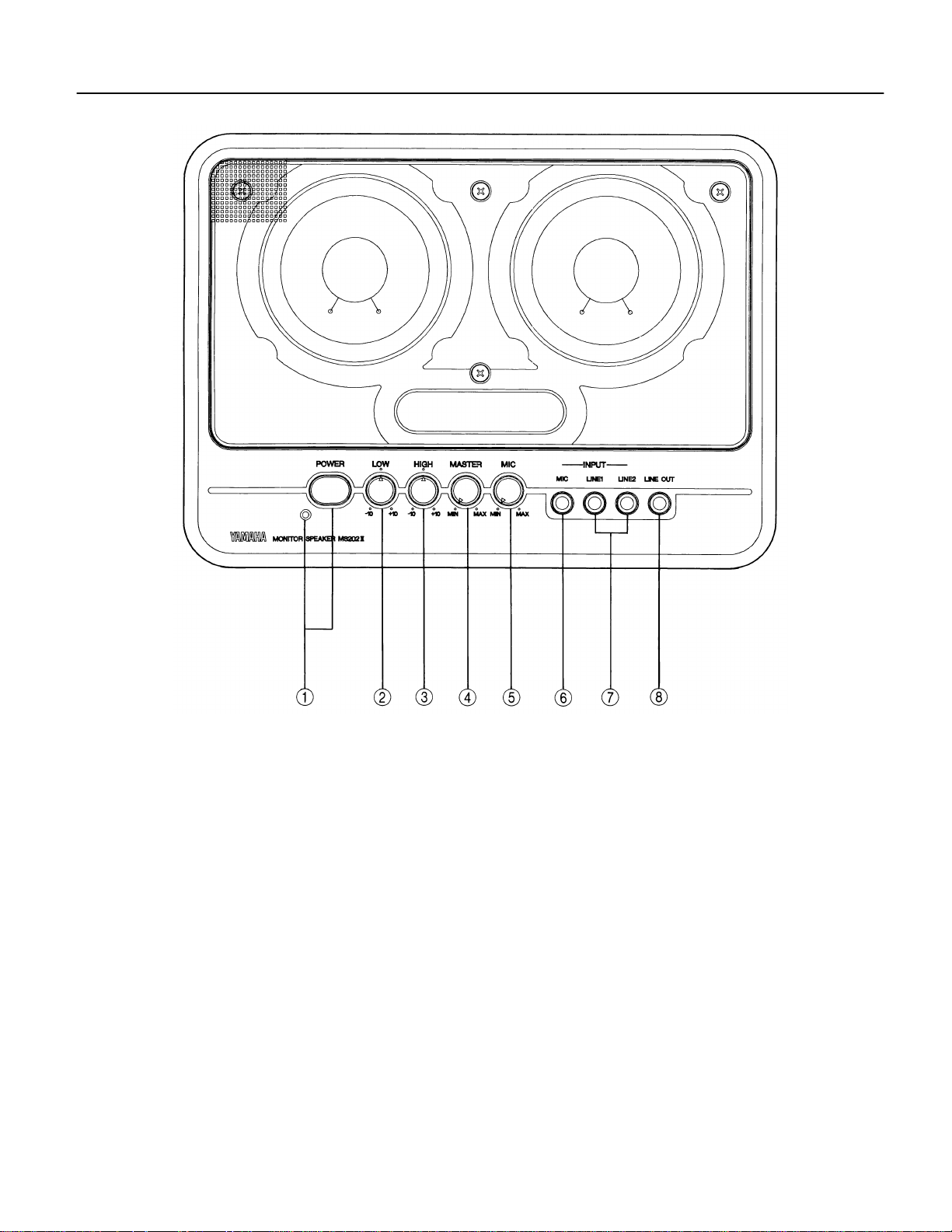
Front Panel
1
POWER Switch & Indicator
Press this switch to power on the MS202 II . Press again to
power off. The power indicator will light up when the power
is on
2
LOW control
Turn this control clockwise to boost low frequencies and
counterclockwise to reduce them.
3
HIGH control
Turn this control clockwise to boost high frequencies and
counterclockwise to reduce them.
4
MASTER V olume
This control can adjust the overall volume level (MIC and
LINE inputs).
5
MIC V olume
This control can adjust the volume level of a microphone
connected to the MIC INPUT jack. If MASTER Volume is
turned all the way down, the mic will not be heard.
6
MIC INPUT
A dynamic type microphone can be connected to this
1/4 inch phone jack.
7
LINE 1, 2 INPUT
Electronic musical instrument such as home keyboard can
be plugged directly into these inputs.
8
LINE OUT
The combined signals from LINE 1, 2, 3 INPUT and MIC
INPUT can be put out from this 1/4” phone jack. You could
connect this LINE OUTPUT to a tape recorder input to be
recorded, or to another powered speaker system for further amplification. The output signal level is not affected by
the MASTER Volume level.
3
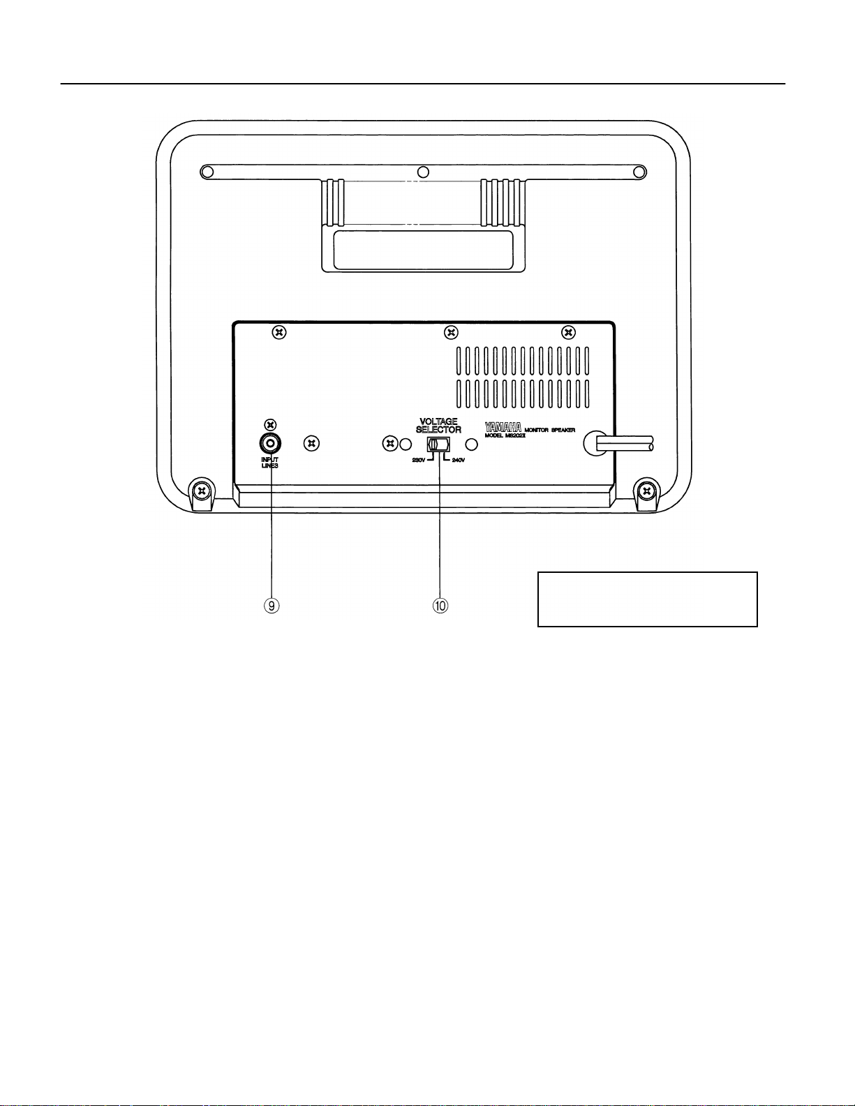
Rear Panel
CAUTION: TO PREVENT ELECTRIC
SHOCK, MATCH WIDE BLADE OF
PLUG TO WIDE SLOT, FULLY INSERT.
9
INPUT LINE 3
The output of any standard audio source can be connected
to this RCA pin jack.
0
VOLTAGE SELECTOR (Only for models other than U.S.
and Canadian models)
Use the voltage selector to match your AC power supply –
either 230V or 240V.
4
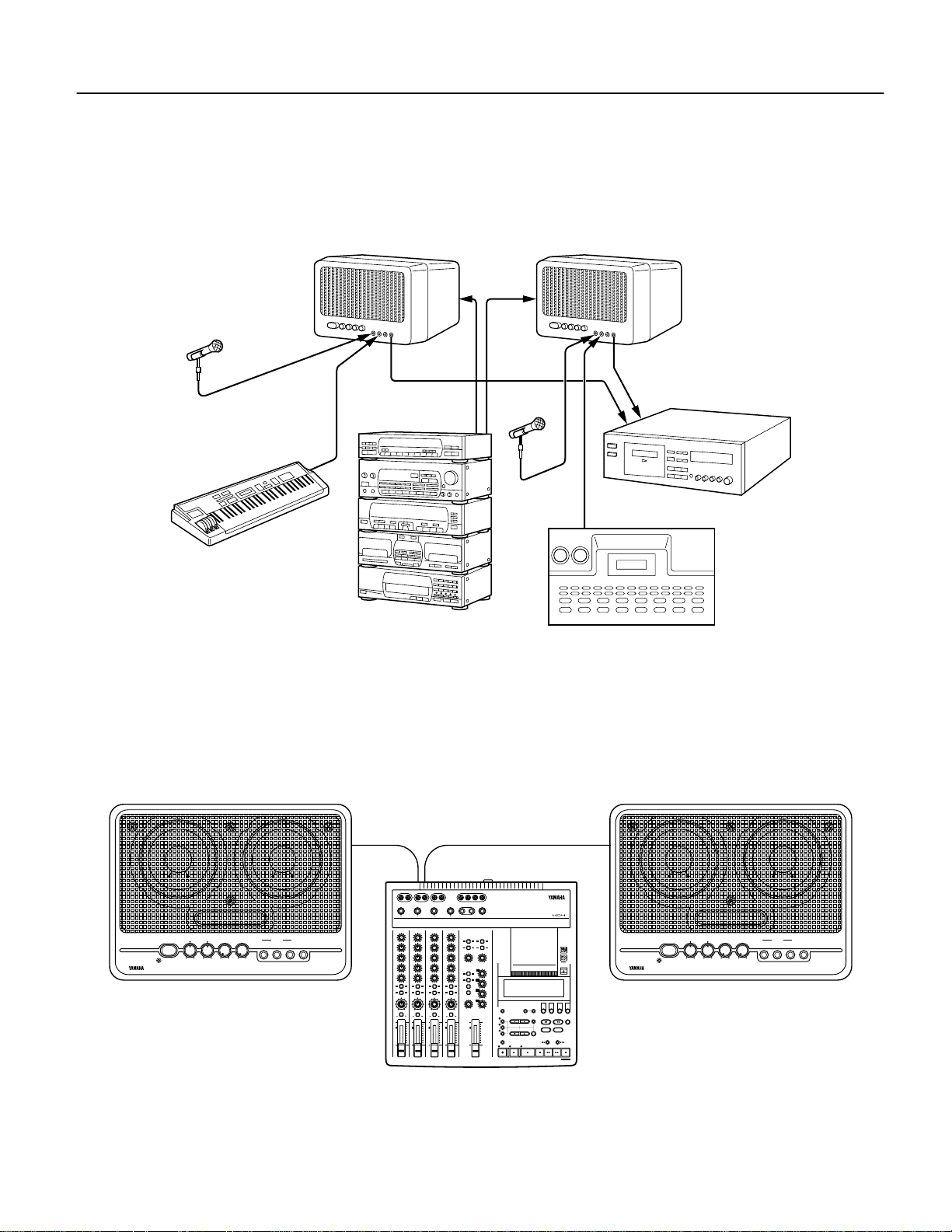
Example Set up
After switching the power off for all components in your system, connect the MS202 II ’s power cable to an AC outlet. There are any
number of ways to use the MS202 II , and exact connections will depend on your system and needs. Here is one example set-up.
A pair of MS202 II can be used as amplification for a stereo monitor system. You can sing and play along with the music on mics and
instruments plugged into the front panel LINE INPUTs. In addition, you can use a pair of MS202 II s for recording if you plug electronic keyboards, rhythm boxes, etc, directly into the LINE INPUTs, and connect the LINE OUT jacks to the inputs of a cassette
recorder.
In this example, the monitor outputs of a Yamaha MD recorder Multitrack are connected to the LINE 2 inputs on a pair of MS202 II s
for multitrack monitoring.
MS2022 MS2022
(Connect to the rear panel LINE INPUTs.)
Mic
Synthesizer
Cassette recorder
Mic
Stereo System
(Tape player, CD player, etc.) Digital rhythm programmer
MONITOR SPEAKER MS2022
MS2022 MS2022
POWER LOW
HIGH
MASTER
MIC
MIN MAX
-10 +10
-10 +10
MIN MAX
L R L R L R
STEREO SUB IN STEREO OUT MONITOR OUT TRACK DIRECT OUT
1234
MIC/LINE INPUT
1
2
34
GAIN
GAIN
GAIN
INPUT
LINE2LINE1
MIC
LINE OUT
LINE MIC
HIGH
–12 +12
MID
–12 +12
LOW
–12 +12
AUX
GROUP ASSIGN
PAN
L
ODDREVEN
PB MIC/
10
9
8
7
6
5
4
3
2
1
0
LINE MIC
HIGH
–12 +12
MID
–12 +12
LOW
–12 +12
AUX
010
1 2
1 2
GROUP ASSIGN GROUP ASSIGN GROUP ASSIGN
3 4
3 4
PAN
L
ODDREVEN
PB MIC/
LINE
10
9
8
7
6
5
4
3
2
1
0
010
GAIN
LINE MIC
LINE MIC
HIGH
HIGH
–12 +12
–12 +12
MID
MID
–12 +12
–12 +12
LOW
LOW
–12 +12
–12 +12
AUX
AUX
010
010
1 2
1 2
3 4
3 4
PAN
PAN
L
L
ODDREVEN
ODDREVEN
PB MIC/
PB MIC/
LINE
LINE
10
10
9
9
8
8
7
7
6
6
5
5
4
4
3
3
2
2
1
1
0
0
LINE
1 2 3 4
L R
AUX RETURN
AUX
RETURN
1 2 1 2
GROUP ASSIGN
3 4 3 4
LEVEL
010
MONITOR
SELECT
1 3
GROUP
2 4
STEREO
CUE
MONITOR LEVEL
MIN MAX
10
9
8
7
6
5
4
3
2
1
0
AUX SEND
MASTER
STEREO
SUB IN
GROUP ASSIGN
LEVEL
010
CUE LEVEL
1
010
2
010
3
010
4
010
STEREO
TIME
DISPLAY
ADJUST
UTILITY
AUTO
PUNCH I/O
REC
REHE
PHONES PUNCH I/O
SELECT
DATA–+
REPEAT MEMO A/B
PLAY
MULTITRACK MD RECORDER
CLEAR
ENTER
PAUSE
123
REC SELECT
MARK SEARCH
LAST REC SEARCH
IN OUT
SONG
SEARCH
REVIEW
FF CUE
MIN MAX
INPUT
MIC
LINE2LINE1
MIC
LINE OUT
POWER LOW
HIGH
MASTER
MIN MAX
-10 +10
MONITOR SPEAKER MS2022
4
MARKPITCH
STOP
TOC WRITE
-10 +10
Multi-track MD recorder
5
Specifications
●
GENERAL SPECIFICATIONS
Type.......................................Bass Reflex Powered Speaker
Frequency Range..................70 Hz — 18 kHz (LOW and HIGH controls at center)
Max. SPL...............................103 dB SPL (20 W, 1 m on axis)
Dimensions (W × H × D)........292 × 214 × 192 mm (11.5 × 8.4 × 7.6 in)
Weight....................................3.9 kg (8 lb 6 oz)
●
SPEAKER SECTION
Components ..........................JA1060 [10 cm (4 in), Cone] × 2
Sensitivity...............................90 dB SPL (1 W, 1 m on axis)
Nominal Impedance...............4 Ω (8 Ω
×
2)
●
AMP. SECTION
Output Power.........................20 W at 1 kHz, THD = 0.5%, RL = 4 Ω
Frequency Response.............40 Hz — 20 kHz
Input Sensitivity......................MIC: –50 dB / 10 k Ω / Phone Jack
/Impedance............................LINE 1: –10 dB / 10 k Ω / Phone Jack
/Connectors LINE 2: –10 dB / 10 k Ω / Phone Jack
LINE 3: –10 dB / 10 k Ω / RCA Pin Jack
LINE OUT: –10 dB / 600 Ω / Phone Jack
Hum & Noise.......................... –73 dB *(VOLUME: min, fc = 12.7 kHz, 6dB / oct LPF)
Controls .................................MASTER, MIC
LOW: ±10 dB — 80 Hz
HIGH: ±10 dB — 10 kHz
POWER: “ON/OFF”
Power Requirement ...............AC120 V, 60 Hz / US & CANADIAN Models
AC230 — 240V, 50/60 Hz / Other Models
Power Consumption...............45 W
* 0 dB = 0.775 Vrms
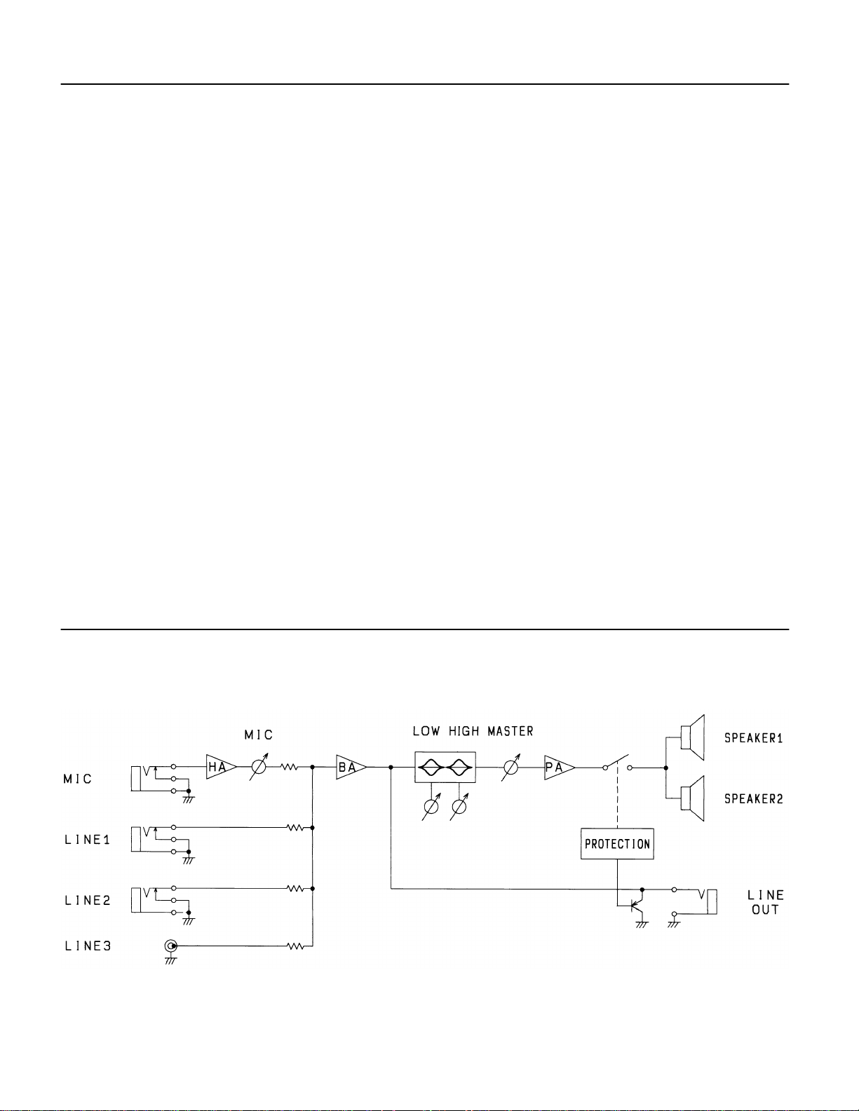
Block Diagram
≤
 Loading...