

Page 1

G B
DISC 1DISC 2DISC 3DISC CHANGE OPEN/CLOSE
3–DISC CD CHANGER
STANDBY TIMER
MINI COMPONENT SYSTEM GX–700
AUTO REVERSE CASSETTE DECK
PUSH OPEN
DOLBY B NR
PROGRAM
DIRECTION
PTY SELECT
B.BOOST
PRESET/TUNING/BAND A/B/C/D/E
DOWN UP
MUSIC
VOLUME
OWNER’S MANUAL
MODE D’EMPLOI
INPUTINPUT
STANDBY/ON
BEDIENUNGSANLEITUNG
BRUKSANVISNING
MANUALE DI ISTRUZIONI
MANUAL DE INSTRUCCIONES
GEBRUIKSAANWIJZING
Page 2
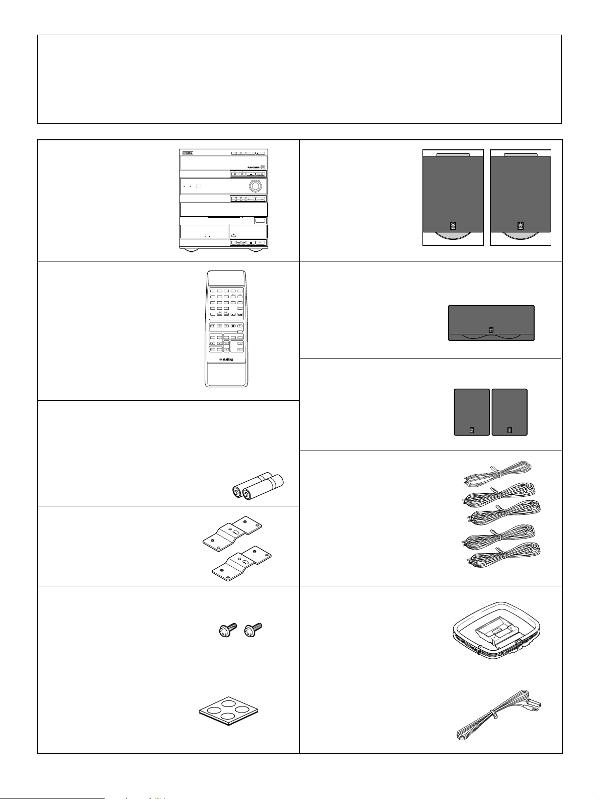
Unpacking ● After unpacking, check that the following parts are contained.
Déballage ● Après le déballage, vérifier que les pièces suivantes sont incluses.
Auspacken ● Nach dem Auspacken überprüfen, ob die folgenden Teile vorhanden sind.
Uppackning ● Kontrollera efter det apparaten packats upp att följande delar finns med.
Disimballaggio ● Verificare che tutte le parti seguenti siano contenute nell’imballaggio dell’apparecchio.
Desembalaje ● Desembale el aparato y verifique que los siguientes accesorios están en la caja.
Uitpakken ● Controleer na het uitpakken of de volgende onderdelen voorhanden zijn.
DISC 1DISC 2DISC
3
● Main unit
● Appareil principal
● Gerät
● Huvudapparat
● Apparecchio principale
● Aparato principal
● Hoofdeenheid
3–DISC CD CHANGER
STANDBY TIMER
PHONES
MINI COMPONENT SYSTEM GX–700
AUTO REVERSE CASSETTE DECK
TREBLEBASS
DOLBY B NR
DISC CHANGE OPEN/CLOSE
PTY SELECT
PRESET/TUNING/BAND A/B/C/D/E
VOLUME
DOWN UP
PROGRAM
B.BOOST
MUSIC
PUSH OPEN
INPUTINPUT
FREQ PS/PTY/RT/CT
MODE–PTY SEEK–START
RANDOM
REPEAT TIME
MIN
HOUR
AUTO/MANUAL
MEMORY
REC/PAUSEDOLBY NR
DISPLAYMODE
TIMER
TIME ADJ
STANDBY/ON
DIRECTION
● Front speakers
● Enceintes avant
● Frontlautsprecherpaar
● Främre högtalare
● Altoparlanti anteriori
● Altavoces delanteros
● Voorluidsprekers
● Remote control
● Télécommande
● Fernbedienung
● Fjärrkontroll
● Telecomando
● Control remoto
● Afstandbediening
112233445
6677889 0
AB
TIME PROG R. TIMECEDIT
MODE REPEAT
RANDOM
DISC SKIP
TUNER
CD
REC/PAUSE
TAPE
CENTER/
REAR/DELAY
PROGRAM
TEST
LEVEL
INPUT
POWER
SLEEP
/I
BOOST
VOLUME
5
PRESET
D
E
+I0
TUNER
DIRECTION
BASS
MUSIC
● Batteries (size AA, UM/SUM-3, R6, HP-7)
● Piles (format AA, UM/SUM-3, R6, HP-7)
● Batterien (Größe AA, UM/SUM-3, R6, HP-7)
● Batterier (Storl. AA, UM/SUM-3, R6, HP-7)
● Batterie (dimensioni AA, o UM/SUM-3, o R6, o HP-7)
● Pilas (tamaño AA, tipo UM/SUM-3, R6, HP-7)
● Batterijen (maat AA, UM/SUM-3, R6, HP-7)
● Mounting brackets
● Supports de montage
● Befestigungshalterungen
● Monteringsfästen
● Staffe di montaggio
● Ménsulas de instalación
● Montagesteunen
● Center speaker
● Enceinte centrale
● Centerlautsprecher
● Mitthögtalare
● Altoparlante centrale
● Altavoz central
● Middenluidspreker
● Rear speakers
● Enceintes arrière
● hinteres Lautsprecherpaar
● Bakre högtalare
● Altoparlanti posteriori
● Altavoces tr aseros
● Achterluidsprekers
● Speaker cords
● Câbles d’enceintes
● Lautsprecherkabel
● Högtalarledningar
● Cavi per gli altoparlanti
● Cables de los altavoces
● Luidsprekerdraden
● Screws
● Vis
● Schrauben
● Skruvar
● Viti
● Tornillos
● Schroeven
● Pads
● Patins
● Auflagen
● Dynor
● Piedini di feltro
● Almohadillas
● Rubber steunen
22
2
● AM loop antenna
● Antenne-cadre AM
● AM-Rahmenantenne
● AM ramantenn
● Antenna ad anello per AM
● Antena de cuadro AM
● AM lusantenne
● Indoor FM antenna
● Antenne intérieure FM
● UKW-Innenantenne
● FM inomhusantenn
● Antenna FM per interni
● Antena interior de FM
● FM binnenantenne
Page 3
,
,
,,,
,,,
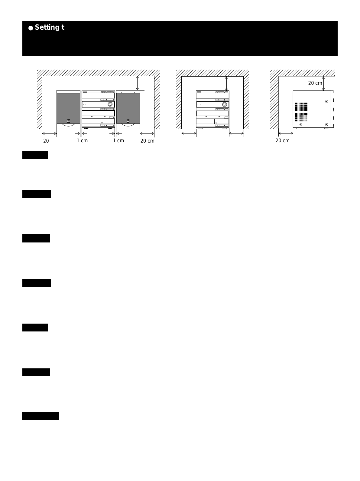
● Setting this system ● Installation de ce système ● Aufstellen des Systems
● Iordningsställande av denna anläggning ● Installazione del sistema
● Instalación del sistema ● Opstelling van dit systeem
20 cm
,,,
1 cm 1 cm
20 cm20 cm
,,
20 cm 20 cm
20 cm
20 cm
20 cm
English
Set this system allowing enough spaces around and behind the main unit to assure good ventilation. Be sure not to place another unit or any object on
top of the main unit to prevent the ventilation holes from being obstructed. Otherwise, it may cause fire or damage to the main unit.
Note: When placing the speakers apart from the main unit, be sure to allow a space of at least 20 cm above, behind and on both sides of the main unit. If
the main unit is put in a rack, the front of it must be fully opened.
Français
Installer ce système en laissant assez d’espace autour et derrière l’appareil principal pour assurer une bonne ventilation. Veiller à ne pas empiler un
autre appareil ou un autre objet sur l’appareil principal afin de ne pas boucher les orifices de ventilation. Sinon, on risquerait de provoquer un
incendie ou d’endommager l’appareil principal.
Remarque: Lorsqu’on place les enceintes à une certaine distance de l’appareil principal, veiller à laisser un espace d’au moins 20 cm au-dessus, derrière
Deutsch
Stellen Sie das System so auf, daß um und hinter dem Gerät genügend freier Raum vorhanden ist, um eine ausreichende Belüftung zu
gewährleisten. Es dürfen keine anderen Geräte oder Gegenstände auf das Gerät gestellt werden, weil die Belüftungsschlitze nicht abgedeckt werden
dürfen. Bei abgedeckten Belüftungsöffnungen kann ein Brand verursacht werden oder das Gerät kann beschädigt werden.
Hinweis: Wenn die Lautsprecher vom Gerät entfernt aufgestellt werden, muß ein freier Abstand von mindestens 20 cm über, hinter und auf beiden Seiten des
et sur les deux côtés de l’appareil principal. Si l’on place l’appareil principal dans un meuble, veiller à ce que le côté avant du meuble soit grand ouvert.
Gerätes vorhanden sein. Wenn das Gerät in einem Regal oder Schrank aufgestellt wird, so muß die Vorderseite vollständig geöffnet sein.
Svenska
Vid placeringen av anläggningen, skall du se till att det finns tillräckligt med fritt utrymme runt om samt bakom huvudapparaten, för att tillförsäkra
en bra ventilation. Var noga med att inte ställa någon annan apparat eller något föremål ovanpå huvudapparaten för att förhindra att
ventilationshålen blir blockerade. Annars kan huvudapparaten utsättas för brand eller skadas på annat sätt.
Anmärkning: När högtalarna ställs separat från huvudapparaten, skall du förvissa dig om att det finns ett fritt utrymme på minst 20 cm ovanför, bakom och på
huvudapparatens båda sidor. Om huvudapparaten placeras i en stereomöbel, måste möbelns framsida lämnas helt öppen.
Italiano
Installare il sistema lasciando sufficiente spazio intorno e dietro all’apparecchio centrale per garantire una ventilazione sufficiente. Evitare
assolutamente di posizionare altri dispositivi o oggetti sulla parte superiore dell’apparecchio centrale onde evitare di ostruirne le aperture per la
ventilazione presenti. In caso contrario possono verificarsi incendi, o l’apparecchio può subire danni.
Nota: Se si installano gli altoparlanti lontano dall’apparecchio principale, quest’ultimo deve essere posizionato in modo da avere almeno 20 cm di spazio libero sopra,
dietro e suoi due lati. Se si installa l’apparecchio principale in uno scaffale, il lato anteriore dello scaffale deve essere completamente aperto.
Español
Instale el sistema dejando suficiente espacio alrededor y detrás de la unidad principal para garantizar una buena circulación de aire. No instale otro
aparato o un objeto encima de la unidad principal porque obstruirá los orificios de salida de aire. Puede provocar un fuego o dañar la unidad
principal.
Nota: Cuando instale los altavoces alejados de la unidad principal, asegúrese de dejar un espacio de por lo menos 20 cm encima, detrás y a ambos lados de la
unidad principal. Si se coloca la unidad principal dentro de un mueble, no debe cerrar la tapa delantera.
Nederlands
Zorg ervoor bij de opstelling van dit systeem dat er voldoende ruimte rondom en aan de achterzijde van de hoofdeenheid is voor het verkrijgen van
een goede ventilatie. Plaats geen andere apparatuur of voorwerpen bovenop de hoofdeenheid om te voorkomen dat de ventilatieopeningen
geblokkeerd raken. Anders kan dit brandgevaar en beschadiging van de hoofdeenheid veroorzaken.
Opmerking: Bij het opstellen van de luidsprekers op afstand van de hoofdeenheid, een ruimte van tenminste 20 cm aan de bovenzijde, achterzijde en aan de
linker en rechter zijde van de hoofdeenheid open laten. Als de hoofdeenheid in een rek wordt geplaatst, dient de voorzijde ervan volledig open te zijn.
33
3
Page 4
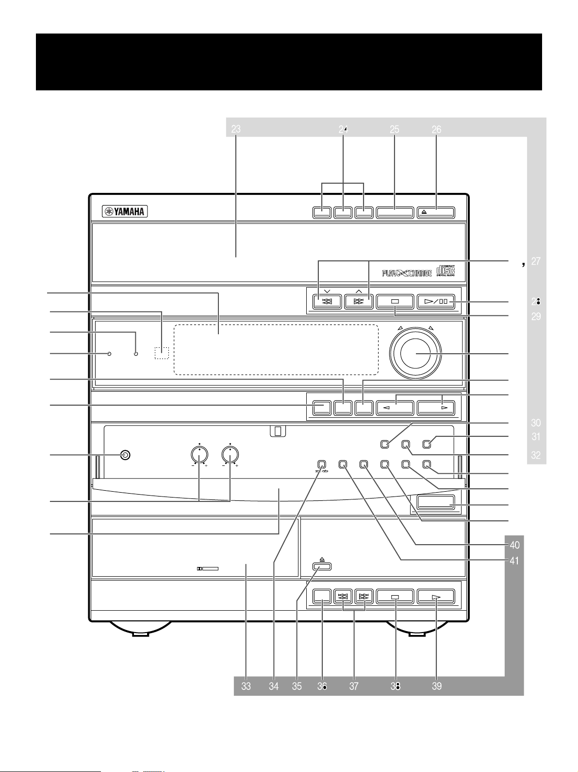
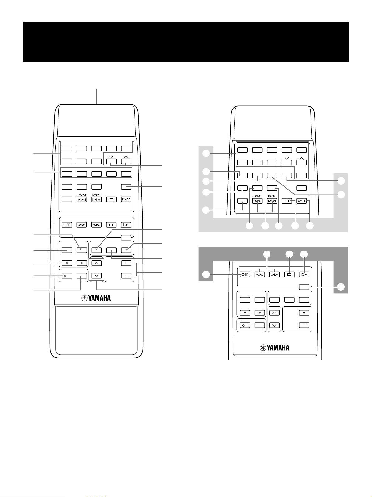
● Front panel ● Panneau avant ● Frontseite
● Frampanelen ● Pannello anteriore ● Panel delantero
● Voorpaneel
1
2
3
4
5
6
–
3
DISC CD CHANGER
STANDBY TIMER
M
DISC 1DISC 2DISC
PTY SELECT
PROGRAM
B.BOOST
MUSIC
ON
3
DISC CHANGE OPEN/CLOSE
PRESET/TUNING/BAND A/B/C/D/E
VOLUME
DOWN UP
P
0, Q
A, R
B, S
C
D
E
INPUTINPUT
7
8
9
PHONES
AUTO REVERSE CASSETTE DECK
DOLBY B NR
FREQ PS/PTY/RT/CT
MODE–PTY SEEK–START
RANDOM
TREBLEBASS
REC/PAUSEDOLBY NR
REPEAT TIME
HOUR
AUTO/MANUAL
MEMORY
TIMER
TIME ADJ
MIN
DISPLAYMODE
G, U
H, V
I
J
F, T
STANDBY/ON
K
L
`
a
DIRECTION
\[YWZX
]
44
4
Page 5
Amplifier/tuner Amplificateur/tuner Verstärker/Tuner
Förstärkare/tuner Amplificatore/sintonizzatore Amplificador/sintonizador
Versterker/tuner
1 Display panel
Panneau d’affichage
Anzeigefeld
Display
Quadrante delle indicazioni
Visualizador
Displaypaneel
2 Remote control sensor
Capteur de télécommande
Fernbedienungssensor
Fjärrkontrollsensor
Sensore del telecomando
Sensor del control remoto
Afstandbedieningsensor
3 TIMER
4 STANDBY [p. 12]
5 B. BOOST [p. 34]
6 PROGRAM [p. 10, 37]
7 PHONES [p. 35]
8 BASS/TREBLE [p. 34]
9 Front cover
Couvercle avant
Reglerfachabdeckung
Frontluckan
Sportello anteriore
Cubierta delantera
Voorklepje
0
/ [p. 18, 19]
PTY SELECT [p. 23]
A A/B/C/D/E [p. 19]
B PRESET/TUNING/BAND
[p. 18]
C V OLUME [p. 34]
D MUSIC [p. 35]
E INPUT (
TUNER → T APE → CD
↑
AUX/MD ← VCR ← VIDEO
/ ) [p. 12, 18, 26, 33]
↓
F FREQ PS/PTY/RT/CT [p. 21]
HOUR [p. 9, 39]
G PTY SEEK START [p. 23]
H PTY SEEK MODE [p. 23]
MIN [p. 9, 39]
I DISPLAY [p. 9, 39]
J MEMORY [p. 19, 20]
TIME ADJ [p. 9]
K STANDBY/ON [p. 10]
L AUTO/MANUAL [p. 18]
TIMER [p. 39]
CD player Lecteur de disque compact CD-Spieler
CD-spelare Lettore CD
Tocadiscos de discos compactos
Compact disc speler
M Disc tray
Plateau de disque
CD-Lade
Skivfack
Piatto portadischi
Plato del disco
Disc-lade
[p. 12]
N DISC (1, 2, 3) [p. 13]
O DISC CHANGE [p. 13]
P OPEN/CLOSE [p. 12]
Q
R
( )/ ( ) [p. 13]
/ [p. 12]
S
[p. 12, 29]
T RANDOM [p. 15]
U TIME [p. 16]
V REPEAT [p. 15]
Tape deck Platine cassette Kassettendeck
Kassettdäck Registratore Platina
Tapedeck
W Tr a y
Plateau
Cassettenlade
Kassettfack
Vano portacassette
Bandeja
Lade
[p. 26]
X MODE [p. 26]
[p. 26]
Y
Z DIRECTION [p. 26]
[
( )/ ( ) [p. 27]
\ [p. 26]
[p. 26]
]
` REC/PAUSE [p. 28]
a DOLBY NR [p. 25, 28]
55
5
Page 6
● Remote control ● Telecommande ● Fernbedienung
● Fjärrkontrollen ● Telecomando ● Control remoto
● Afstandbediening
1
2
3
4
5
6
7
8
112233445
6677889 0
RANDOM
CD
BASS
PROGRAM
BOOST
INPUT
VOLUME
D
AB
TIME PROG R. TIMECEDIT
MODE REPEAT
DISC SKIP
TUNER
REC/PAUSE
TAPE
CENTER
/
REAR/DELAY
TEST
LEVEL
POWER
SLEEP
/I
5
PRESET
E
+I0
TUNER
DIRECTION
MUSIC
9
0
A
B
C
D
E
F
G
H
I
J
R
112233445
CD
PRESET
D
+I0
TUNER
6677889 0
AB
TIME PROG R. TIMECEDIT
MODE REPEAT
DISC SKIP
RANDOM
TUNER
KLMNO
UTS
REC/PAUSE
CENTER
/
REAR/DELAY
LEVEL
POWER
/I
TEST
SLEEP
TAPE
PROGRAM
INPUT
BASS
BOOST
VOLUME
DIRECTION
MUSIC
5
E
P
Q
V
66
6
Page 7

Amplifier/tuner Amplificateur/tuner Verstärker/Tuner
Förstärkare/tuner Amplificatore/sintonizzatore Amplificador/sintonizador
Ver sterker/tuner
1 T ransmission window
Fenêtre de transmission
Übertragungsfenster
Fjärrkontrollsändare
Apertura di emissione dei raggi infrarossi
Ventanilla de transmisión
Signaalvenster
[p. 4]
2 Numeric buttons
Touches numériques
Zahlentasten
Sifferknappar
Tasti numerici
Botones numéricos
Cijfertoetsen
[p. 19]
4 TEST [p. 10]
5 CENTER/REAR/DELAY
[p. 37]
6 LEVEL (+/–)
[p. 10, 37]
7 POWER [p. 10]
8 SLEEP [p. 40]
9 PRESET (
[p. 19]
/ )
0 TUNER [p. 18]
A PROGRAM [p. 10, 37]
3 A, B, C, D, E [p. 19]
B MUSIC [p. 35]
CD player Lecteur de disque compact CD-Spieler
CD-spelare Lettore CD
Compact disc speler
Tocadiscos de discos compactos
C BASS BOOST
[p. 34]
D VOLUME (+/–)
[p. 34]
E INPUT ( / )
[p. 12, 18, 26, 33]
TUNER → TAPE
↑↓
AUX/MD CD
↑↓
VCR ← VIDEO
F Numeric buttons
Touches numériques
Zahlentasten
Sifferknappar
Tasti numerici
Botones numéricos
Cijfertoetsen
[p. 13]
H PROG [p. 14]
I MODE [p. 12]
J DISC SKIP [p. 13]
K REPEAT [p. 15]
L
( )/ ( ) [p. 13]
M RANDOM [p. 15]
N [p. 12]
O
[p. 12]
P EDIT [p. 30]
Q R. TIME [p. 30]
G TIME [p. 13]
Tape deck Platine cassette Kassettendeck
Kassettdäck registratore Platina
Tapedeck
R REC/PAUSE [p. 28]
S
/ [p. 27]
T
U
[p. 26]
[p. 26]
V DIRECTION [p. 26]
77
7
Page 8
Thank you for purchasing this YAMAHA product. We hope it will give you many years of trouble-free enjoyment.
Contents
English
For the best performance, read this manual carefully. It will guide you in operating your YAMAHA product.
Page
Precautions.................................................
Features ......................................................
Preparations and connections..................
Installing batteries in the remote control ..................4
Remote control operation range .............................. 4
Setting up the speakers ...........................................5
Connections ............................................................. 7
Setting the clock.......................................................9
Adjusting brightness of the display .......................... 9
Speaker balance adjustment ................................. 10
Compact disc player operation...............
Basic play...............................................................12
To change the disc play mode ............................... 12
To select another disc ............................................ 13
To select the desired track directly ......................... 13
To play the desired track (Skip).............................. 13
To advance or reverse play rapidly (Search) .......... 13
To exchange a disc (or discs) while playing
(PLAYXCHANGE) ..................................................13
Program play..........................................................14
Random play.......................................................... 15
Repeat play............................................................ 15
Switching the time display......................................16
Tuning operation ......................................
Automatic tuning ....................................................18
Manual tuning ........................................................ 18
Manual preset tuning ............................................. 19
Automatic preset tuning .........................................20
Receiving RDS stations .................................. 21
11
17
Page
1
3
4
Playing back a tape..................................
General information ............................................... 25
Basic operation ......................................................26
Winding the tape .................................................... 27
Searching for the beginning
of the desired selection .......................................... 27
Recording .................................................
Basic recording ......................................................28
Recording from CDs utilizing the EDIT function..... 30
25
28
Operating the external units connected
with this system .......................................
Various sound control .............................
General sound control............................................34
Graphic equalizer................................................... 35
Sound field processor ............................................36
Using the built-in timer ............................
Timer play ..............................................................39
Timer recording...................................................... 40
Sleep timer operation............................................. 40
Appendix...................................................
Troubleshooting .....................................................41
Specifications......................................................... 43
For basic source play, the following illustrations on top of
pages will help you to look for the section you need.
...... CD play ......Tuning
...... Tape playback/recording
33
34
39
41
Page 9

Precautions: Read this before operating your system
English
■ To assure the finest performance, please read this manual
carefully. Keep it in a safe place for future reference.
■ Choose the installation location of this system carefully.
Avoid placing it in direct sunlight or close to a source of
heat. Also avoid locations subject to vibration and
excessive dust, heat, cold or moisture. Keep it away from
sources of hum such as transformers and electric motors.
■ Do not operate this system upside-down. It may overheat,
possibly causing damage.
■ Never open the cabinet. If something drops into the set,
contact your dealer.
■ The openings on the main unit cover assure proper
ventilation of the main unit. If these openings are
obstructed, the temperature inside the unit will rise rapidly.
Therefore, avoid placing objects against these openings,
and install the main unit in a well-ventilated area to
prevent fire and damage.
■ Always set the VOLUME control to minimum before
starting an audio source play: increase the volume
gradually to an appropriate level after play has started.
■ When not planning to use this system for long periods of
time (ie., vacation, etc.), disconnect the AC power plug
from the wall outlet.
■ Grounding or polarization – Precautions should be taken
so that the grounding or polarization of this system is not
defeated.
■ Do not use force on switches, controls or connection
wires. When moving the main unit, first disconnect the
power plug and the wires connected to other equipment.
Never pull the wire itself.
■ If an external appliance (TV, radio, etc.) interferes with this
system operation, move the main unit away from such an
appliance.
■ Do not attempt to clean this system with chemical
solvents; this might damage the finish. Use a clean, dry
cloth.
■ Be sure to read the “Troubleshooting” section regarding
common operating errors before concluding that this
system is faulty.
■ To prevent lightning damage, disconnect the AC power
plug and the antenna cable when there is an electrical
storm.
■ Do not plug the AC power plug to the wall socket before
you finish all connections.
■ Never allow metallic items (e.g. screwdrivers, tools, etc.) to
come near the tape deck’s record/playback head
assembly. Doing so may not only scratch or damage the
head’s mirror-smooth finish, it may change the magnetic
characteristics of the heads, causing a deterioration in
reproduction performance quality.
■ Although the tape deck’s record/playback heads are high
quality heads with outstanding reproduction
characteristics, they can become dirty through the use of
old tapes or from dust accumulation over time. This can
have a serious effect on reproduction quality. Clean the
heads regularly with one of the commonly available head
cleaners or with cleaning solutions.
■ The voltage to be used must be the same as that specified
on this system. Using this system with a higher voltage
than specified is dangerous and may result in a fire or
other types of accidents causing damage. YAMAHA will
not be held responsible for any damage resulting from use
of this system with a voltage other than specified.
■ The sound level at a given volume setting depends on
speaker location and other factors. Care should be taken
to avoid exposure to sudden high levels of sound, which
may occur when turning on this system with the volume
control setting at high, and to continuous high levels of
sound.
■ Sudden temperature changes and storage or operation in
an extremely humid environment may cause condensation
inside the cabinet. Condensation can cause this system to
malfunction.
To eliminate condensation:
CD pickup
•
Leave the power on with no disc loaded until normal
play becomes possible (about 1 hour).
Tape head
•
Leave the power on with no tape loaded until normal
playback becomes possible (about 1 hour).
Note
If condensation forms on the tape head, dirt or dust
may accumulate during use.
Remote control
•
Wipe off condensation on the transmission window
with a soft cloth before operating this system.
■ To prevent a malfunction of this system:
Do not use any non standard shaped disc (heart etc.)
•
available on the market, because it may damage this
system.
Do not use a disc with tape, seals, or paste on it,
•
because damage to this system may result.
This system is not disconnected from the AC power
source as long as it is connected to the wall outlet, even if
this system itself is turned off. This state is called the
standby mode.
In this state, this system is designed to consume a certain
level of power.
Note
Please check the copyright laws in your country to record
from records, compact discs, radio, etc. Recording of
copyright material may infringe copyright laws.
E-1
Page 10

Precautions: Read this before operating your system
CLASS 1 LASER PRODUCT
CAUTION FOR CARRYING THE MAIN UNIT
Be sure not to carry or tip the main unit with discs
remaining in it.
CAUTION FOR MOVING THE MAIN UNIT
Before moving the main unit, first remove all discs from
the disc tray and close the tray by pressing the OPEN/
CLOSE button. After you confirm that “NO DISC” lights up
on the display, turn this system into the standby mode by
pressing the STANDBY/ON switch, and then disconnect
the power plug from the AC outlet.
For U.K. customers
If the socket outlets in the home are not suitable for the plug
supplied with this appliance, it should be cut off and an
appropriate 3 pin plug fitted. For details, refer to the
instructions described below.
Note: The plug severed from the mains lead must be
destroyed, as a plug with bared flexible cord is hazardous if
engaged in a live socket outlet.
SPECIAL INSTRUCTIONS FOR U.K. MODEL
IMPORTANT:
THE WIRES IN MAINS LEAD ARE COLOURED IN
ACCORDANCE WITH THE FOLLOWING CODE:
Blue: NEUTRAL
Brown: LIVE
As the colours of the wires in the mains lead of this
apparatus may not correspond with the coloured markings
identifying the terminals in your plug, proceed as follows:
The wire which is coloured BLUE must be connected to the
terminal which is marked with the letter N or coloured
BLACK. The wire which is coloured BROWN must be
connected to the terminal which is marked with the letter L
or coloured RED. Making sure that neither core is
connected to the earth terminal of the three pin plug.
IMPORTANT
Please record the serial number of this system in the space
below.
Model:
Serial No.:
The serial number is located on the rear of the main unit.
Retain this Owner’s Manual in a safe place for future
reference.
WARNING
TO REDUCE THE RISK OF FIRE OR ELECTRIC SHOCK,
DO NOT EXPOSE THIS APPLIANCE TO RAIN OR
MOISTURE.
WARNING
To reduce the risk of fire or electric shock, do not expose this
system to rain or moisture.
To avoid electrical shock, do not open the cabinet. Refer
servicing to qualified personnel only.
CAUTION
Use of controls or adjustments or performance of
procedures other than those specified herein may result in
hazardous radiation exposure.
As the laser beam used in this system is harmful to the
eyes, do not attempt to disassemble the cabinet. Refer
servicing to qualified personnel only.
This system is classified as a
CLASS 1 LASER product.
The CLASS 1 LASER
PRODUCT label is located on
the rear exterior.
E-2
Laser component in this product is capable of emitting
radiation exceeding the limit for Class 1.
Page 11

Features
English
General
5-Speaker Multichannel Audio System
●
(Two front, One Center and Two Rear
Speakers)
●
High Power Output
Front L, R: 80W + 80W (6Ω) RMS, 0.9%
THD, 1 kHz
Center: 80W (6Ω) RMS Output
Power,
Rear: 25W (6Ω) RMS Output
Power,
0.9% THD, 1 kHz
0.9% THD, 1 kHz
● 4 External Audio/Video Component
Connecting Capability
● Multiuse Timer/Sleep Timer
● SUBWOOFER Output for Low Frequency
Expansion
● Remote Control Capability
● BASS BOOST
Compact Disc Player
● 3-Disc Carousel Type CD Changer
● PLAYXCHANGE
Disc changing while playing
● 20-Track Random Access Programming
● Repeat Play for Single Track/Entire Disc/
All Discs
● Random Sequence Play
Tape Deck
● Automatic Synchronized Recording with
CD
● EDIT Function Useful for Recording
CD(s)
●
Automatic Reverse
●
Dolby B Type Noise Reduction System
● 5-Band Spectrum Analyzer
● DOLBY PRO LOGIC and DOLBY 3
STEREO Decoding
● Sound Field Processing
(HALL and YMERSION)
● Test Tone Generator for Easier Speaker
Balance Adjustment
● 3 Preset Graphic Equalizer Modes
(ROCK, POPS and JAZZ)
Tuner
●
40 Station Preset Tuning
●
Automatic Preset Tuning
●
Multi-Function RDS Reception
E-3
Page 12
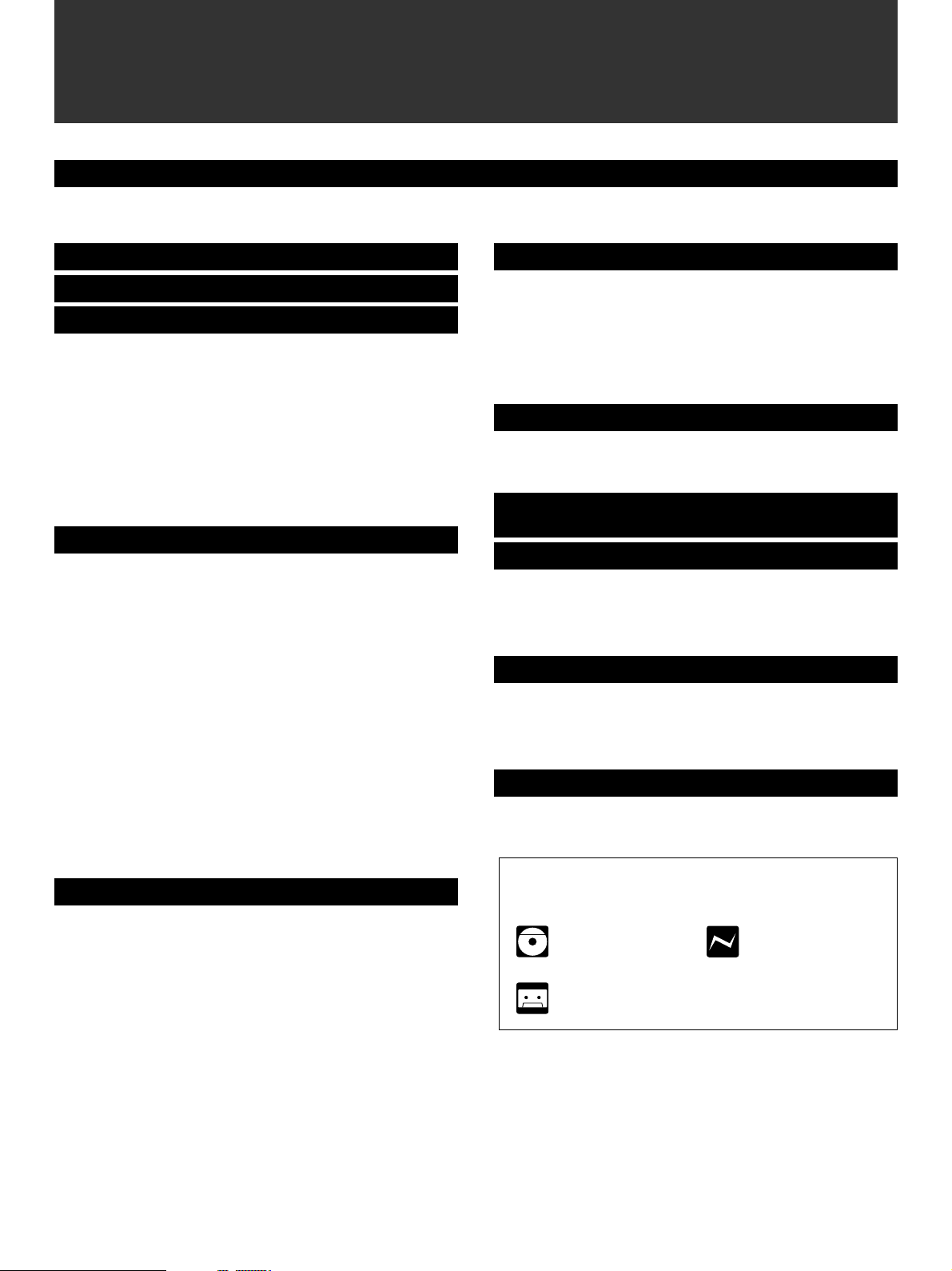
Preparations and connections
Installing batteries in the remote control
2
1
3
1. Turn the remote control over and remove the battery
compartment cover by pulling it up while pressing the edge
of the cover in the direction of the mark.
2. Insert the batteries (AA, R6, UM-3 type) according to the
polarity markings on the inside of the battery compartment.
3. Attach the battery compartment cover.
Notes
● Remove the batteries if the remote control is not used for an
extended period of time.
● If batteries leak, dispose of them immediately. Avoid
touching the leaked material and contact with clothing, etc.
Clean the battery compartment thoroughly before installing
new batteries.
● Be sure to use the same type of batteries together.
● Do not use a new battery and an old battery together.
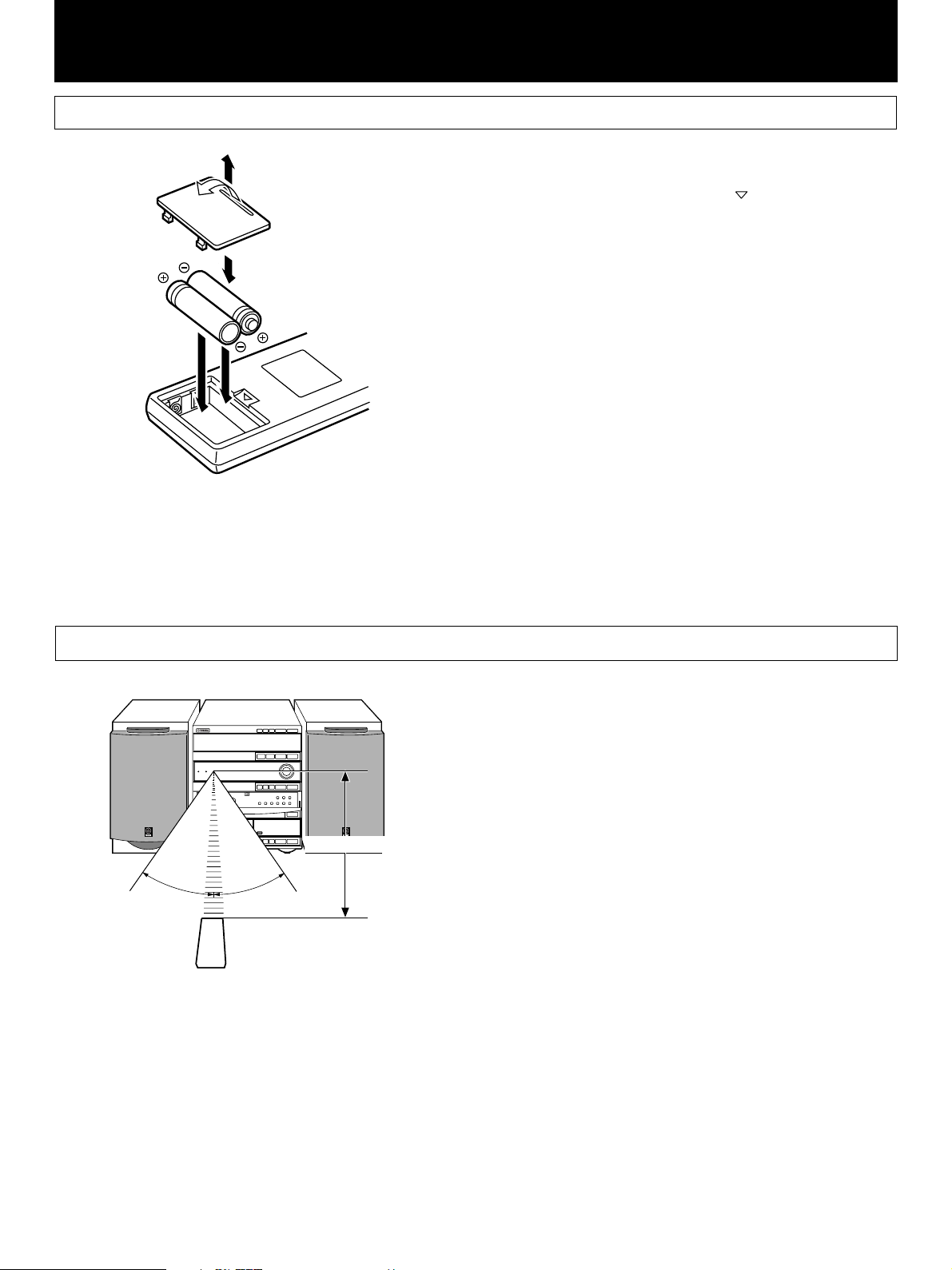
Remote control operation range
DISC 1DISC 2DISC
3
DISC CHANGE OPEN/CLOSE
3–DISC VCD CHANGER
MINI COMPONENT SYSTEM GX–700
30°
PUSH OPEN
30°
SET MD
PRESET/TUNING/BAND A/B/C/D/E
REC/PAUSE
TAPE
MINIDISC RECORDER
DOWN UP
VOLUME
MODE–PTY SEEK–START
MD
0,2 m – 6 m
Notes
● The area between the remote control and the main unit must
be clear of large obstacles.
● Do not expose the remote control sensor to strong lighting,
in particular, an inverter type fluorescent lamp. Otherwise,
the remote control may not work properly. If necessary,
position the main unit away from direct lighting.
Battery replacement
If you find that the remote control must be used closer to the
main unit, the batteries are weak. Replace both batteries with
new ones.
E-4
Page 13
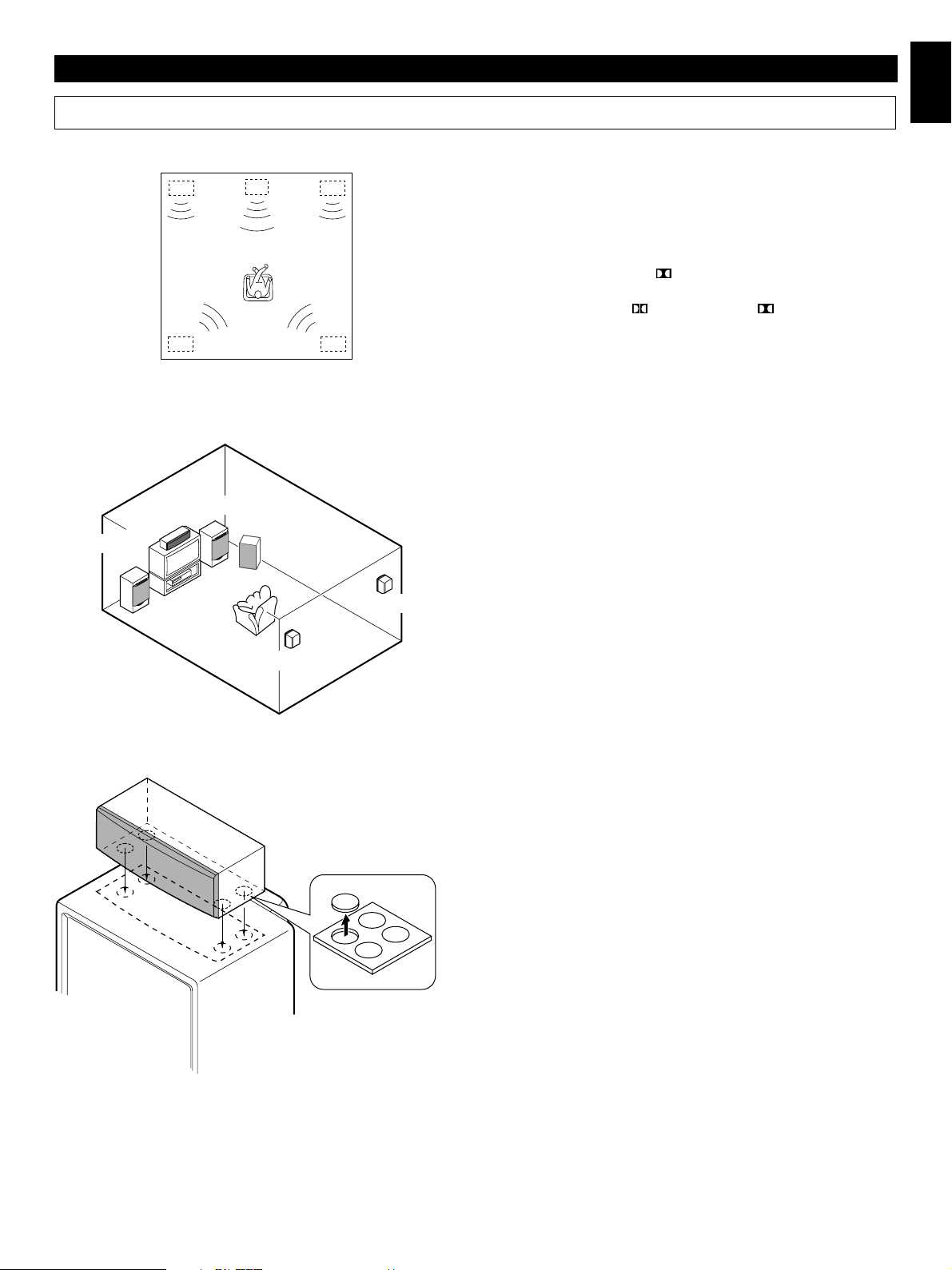
Setting up the speakers
English
Preparations and connections
Front L
Front L Center Front R
DialogueDialogo
Rear L Rear R
Rear L
Center
Front R
Subwoofer
TV set
Rear R
Rear R
m 4 channel 5 speaker configuration
This system employs a 5 speaker configuration: 2 front
speakers, 2 rear paralleled speakers and a center speaker.
The front speakers are used for outputting main source sound.
The rear speakers are for effect and surround sounds when
the sound field program
The center speaker is for center sounds (dialog etc.) when the
sound field program
selected.
PRO LOGIC or HALL is selected.
PRO LOGIC or 3 STEREO is
m Placing the speakers
Front speakers: On both sides of the TV and almost the
same height as the TV.
Center speaker: Precisely between the front speakers.
Rear speakers: Behind your listening position, facing
slightly inward. Nearly 1.8 m (approx. six
feet) up from the floor.
Subwoofer: The position of the subwoofer is not so
(separate purchase)
critical because low bass tones are not
highly directional.
Rear L
m Mounting the center speaker
Place the center speaker on the TV, on the floor under the TV
or in the TV rack so that it is stabilized.
When placing the speaker on top of the TV, to prevent the
speaker from falling down, put the provided pads at four points
on bottom of the speaker.
E-5
Page 14
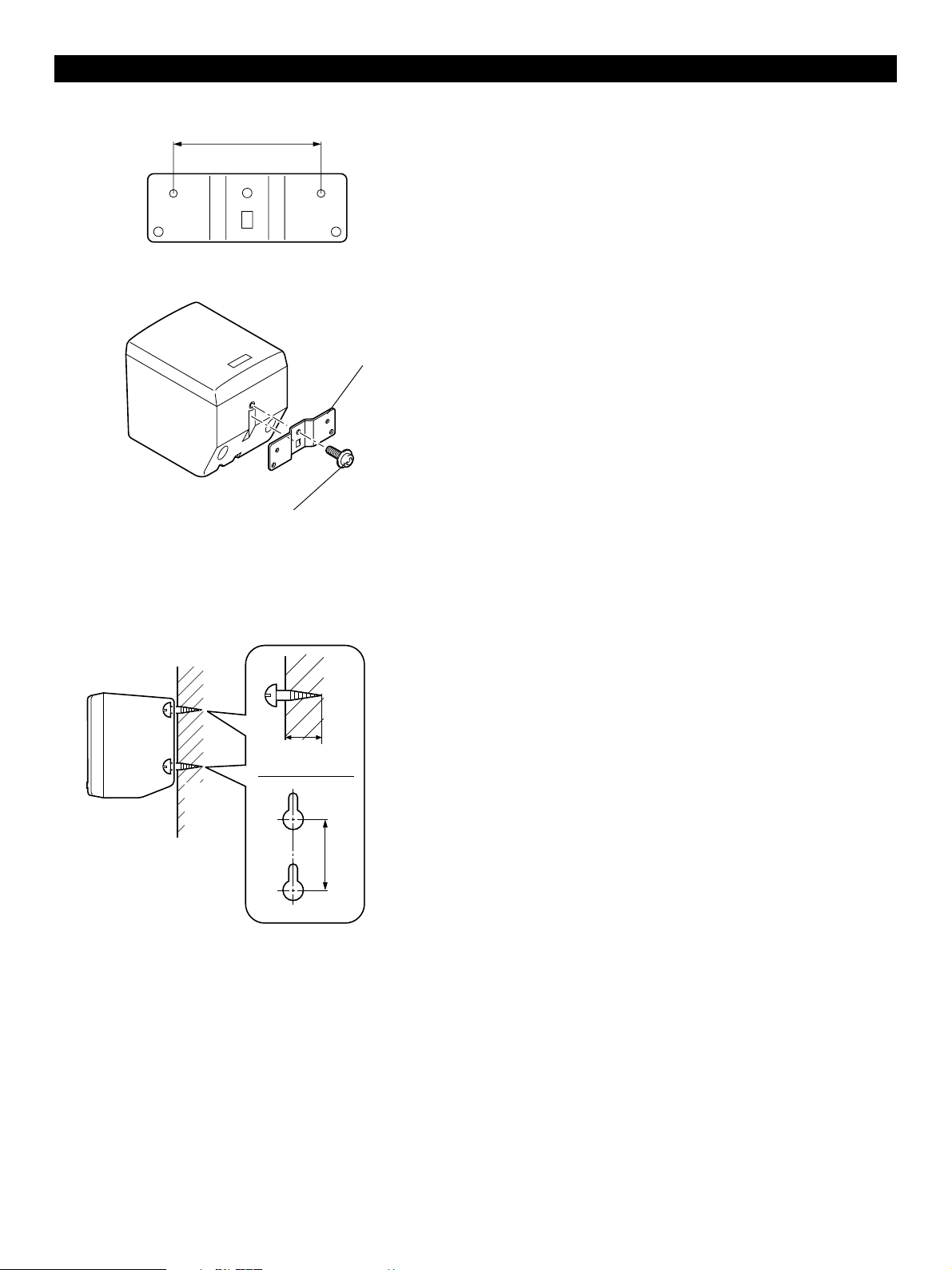
Preparations and connections
60 mm
Screw
Mounting
bracket
m Mounting the rear speakers
Mount the rear speakers on a shelf, rack or on the floor, or
hang them on the wall.
To mount the rear speakers on the wall by using
commercially available speaker stands
The provided mounting bracket has 1 pair of screw holes (at
an interval of 60 mm). They are available for mounting the
speaker on a speaker stand.
* Those screw holes can be used with M4 screws only.
Note
It is recommended that you connect the speaker cords to the
speaker’s terminals before attaching the bracket to the
speaker.
1 Attach the bracket to the bottom of the speaker by using
the provided screw so that the convex part of the bracket
fits in the grooved part of the speaker as figured left.
2 Mount the speaker on the speaker stand by using the
screw holes on the bracket.
Wall or wall
Tapping screw
(Available at the
hardware store)
support
Min.
12 mm
65 mm
To mount the rear speakers on the wall without
using any bracket or stand
If desired, you can hang the speaker on the protruding screws
on the wall without using the bracket.
Fasten screws into a firm wall or wall support as figured left,
and hang the holes of the speaker on the protruding screws.
* Make sure that the screws are caught by a narrow part of
the holes securely.
WARNING:
● Each of the rear speakers weighs 0.8 kg (1 lbs. 12 oz.).
Do not mount them on thin plywood or soft wall
surface material, as the screws may come out of the
flimsy surface, causing the speakers to fall down and
be damaged, or result in personal injury.
● Do not fasten the speakers to the wall with nails,
adhesives, or other unsound hardware. Long-term use
and vibrations may cause them to fall down.
● To avoid accidents resulting from tripping over loose
speaker cords, fix them to the wall.
● Select a proper position on the wall to mount the
speaker and the stand so that no one will hit his head
or forehead on the projections of them, resulting in
personal injury.
E-6
Page 15
Preparations and connections
1
2
3
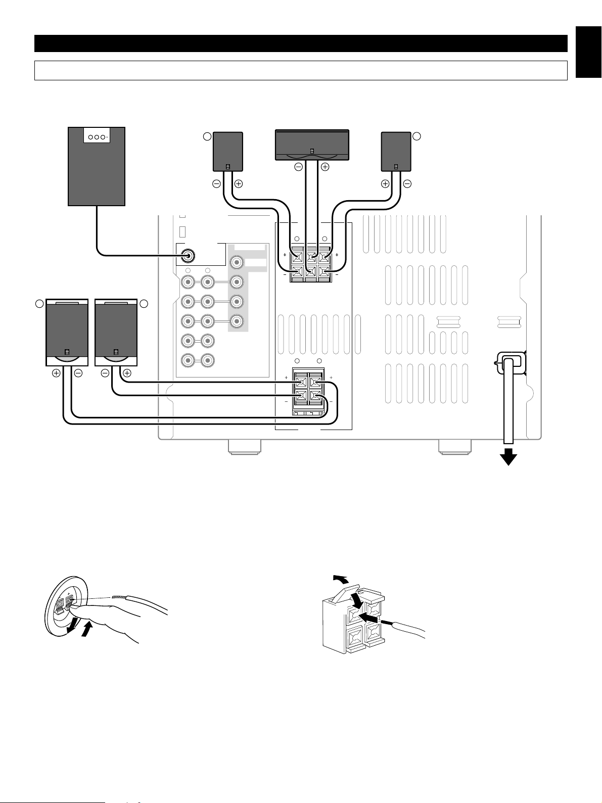
Connections
Never plug the AC supply lead of this system into the AC outlet until all connections are completed.
Subwoofer system
(Separate purchase)
Rear speaker
R
Center speaker
Rear speaker
L
English
INPUT
Front speakers
L R
m Connecting speakers
SUBWOOFER
OUT
RL
OUT
AUX/MD
IN
VIDEO SIGNAL
MONITOR
OUT
OUT
VCR
IN
VIDEO
SPEAKERS
SEE OWNER’S MANUAL
FOR CONNECTION.
R L
CENTERREAR REAR
CENTER: 6Ω MIN./SPEAKER
Ω
MIN./SPEAKER
REAR: I2
FRONT
R L
6Ω MIN./SPEAKER
SPEAKERS
MAINS
To AC outlet
Connect the speakers to the corresponding speaker terminals on the rear of the main unit respectively by using the speaker cords.
Make sure that the polarity of the speaker cords is correct, that is the + and – markings are observed. If these cords are reversed,
the sound will be unnatural and lack bass.
On the speakers
Red: positive (+)
Black: negative (–) 1 Press the tab
2 Insert the bare wire.
2
[Remove approx. 5mm
(1/4”) insulation from
the speaker wires.]
3 Release the tab and
secure the wire.
1
3
Caution
Do not let the bare speaker wires touch each other as this could damage the amplifier and/or speakers.
When connecting a subwoofer (separate purchase)
You may wish to add a subwoofer to reinforce the bass frequencies.
When connecting a subwoofer to this system, connect the SUBWOOFER OUT terminal of this system to the INPUT terminal of the
subwoofer.
* Ordinary subwoofers, including the Yamaha Active Servo Processing Subwoofer System, are designed so that the amplifier and
subwoofer are in the same unit.
* The SUBWOOFER OUT terminal outputs low frequencies from the left front, center and right front channels.
(The cut-off frequency of this terminal is 200 Hz.)
On the main unit
Red: positive (+)
Black: negative (–)
1 Press up the tab.
2 Insert the bare wire.
[Remove approx. 5mm (1/4”)
insulation from the speaker
wires.]
3 Press down the tab and
secure the wire.
E-7
Page 16
Preparations and connections
M
O
S
S
L
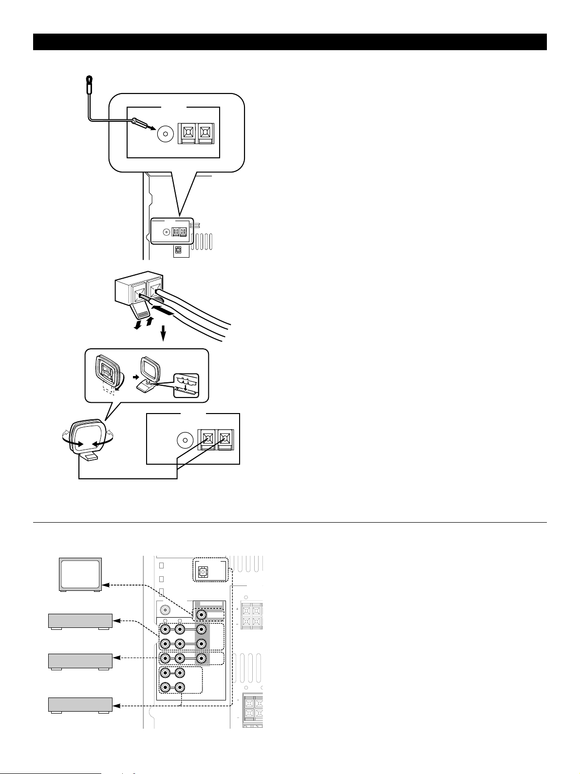
m Antenna connection
(1)
(2)
ANTENNA
FM GND AM
75Ω UNBAL.
ANTENNA
FM GND AM
75Ω UNBAL.
DIGITAL OUT
OPTICAL
(1) Supplied FM antenna
Connect the FM antenna wire to the corresponding terminal
and direct the FM antenna wire to the direction where the
strongest signal can be received.
(2) Supplied AM loop antenna
Connect the AM loop antenna wires to the corresponding
terminals. Position the AM loop antenna for optimum
reception.
Notes
● When static is still heard even after adjusting the position of
the AM loop antenna, try reversing the wire connections
(from the right terminal to the left one, and vice versa).
● The AM loop antenna should be placed apart from the main
unit. The antenna may be hung on a wall.
Using an external antenna
● Use an external FM antenna instead of an indoor FM
antenna if you need better reception. Consult your dealer.
● Use an external AM antenna if you need better reception.
Consult your dealer.
TV monitor
VCR
LD/DVD player, etc.
MD recorder, etc.
ANTENNA
FM GND AM
75Ω UNBAL.
SUBWOOFER
OUT
RL
OUT
AUX/MD
IN
DIGITAL OUT
OPTICAL
VIDEO SIGNAL
MONITOR
OUT
OUT
VCR
IN
VIDEO
SPEAKERS
SEE OWNER’S
FOR CONNECTI
R
CENTERREAR
CENTER: 6Ω MIN./
REAR: I2Ω MIN./
FRONT
R
m Connecting external components
This system can be connected with external audio and video
components. Make connections between this system and the
components using RCA pin plug connector cables correctly,
that is to say L (left) to L and R (right) to R. Also, refer to the
owner’s manual for the component to be connected to this
system.
* A digital-to-digital recording is possible from a CD played on
the built-in CD player to an MD (or tape) on an external MD
recorder (or DAT) by connecting the DIGITAL OUT
(OPTICAL) terminal on the rear of the main unit to the MD
recorder (or DAT).
E-8
Page 17

Setting the clock
3–DISC CD CHANGER
STANDBY TIMER
PHONES
TREBLEBASS
DISC 1DISC 2DISC
PTY SELECT
PROGRAM
B.BOOST
3
PRESET/TUNING/BAND A/B/C/D/E
MUSIC
FREQ PS/PTY/RT/CT
RANDOM
HOUR
AUTO/MANUAL
REC/PAUSEDOLBY NR
TIMER
DISC CHANGE OPEN/CLOSE
VOLUME
DOWN UP
INPUTINPUT
MODE–PTY SEEK–START
REPEAT TIME
MIN
MEMORY
DISPLAYMODE
TIME ADJ
STANDBY/ON
English
Preparations and connections
1 While the power is on, press DISPLAY to display the time.
2 While holding TIME ADJ pressed, press HOUR and set the
hour.
* Press HOUR once to advance the time by 1hour. Press
and hold to advance continuously.
3 While holding TIME ADJ pressed, press MIN and set the
minute.
* Press MIN once to advance the time by 1
minute. Press and hold to advance continuously.
* The hour setting will not advance even if minute is
advanced from “59” to “00”.
DISPLAY
MODE–PTY
REPEAT
MIN
DOLBY B NR
DIRECTION
MEMORY
TIME ADJ
AUTO REVERSE CASSETTE DECK
1
FREQ PS/PTY/RT/CT
2
RANDOM
HOUR
Changes.
FREQ PS/PTY/RT/CT
3
RANDOM
HOUR
MODE–PTY
REPEAT
MIN
MEMORY
TIME ADJ
Changes.
Adjusting brightness of the display
Note
In the event of a power failure or when the AC supply lead is
disconnected, the time display will go out, however, the clock
will function for about 5 minutes without any po wer supply.
Otherwise, the time display will flash on and off to indicate that
the time must be reset.
If desired, you can adjust the brightness of the display.
DISC 1DISC 2DISC
3
DISC CHANGE OPEN/CLOSE
PTY SELECT
PRESET/TUNING/BAND A/B/C/D/E
VOLUME
DOWN UP
PROGRAM
B.BOOST
MUSIC
REC/PAUSEDOLBY NR
FREQ PS/PTY/RT/CT
MODE–PTY SEEK–START
RANDOM
REPEAT TIME
MIN
HOUR
AUTO/MANUAL
MEMORY
TIMER
TIME ADJ
INPUTINPUT
DISPLAYMODE
STANDBY/ON
Press and hold DISPLAY for more than 2 seconds so that
“DIMMER ±0” appears on the display.
While holding DISPLAY pressed, turn VOLUME clockwise to
increase or counterclockwise to decrease brightness.
VOLUME
Control range: ±0 to –6 (Preset value: ±0)
DISPLAY
E-9
Page 18

Preparations and connections
Speaker balance adjustment
You can adjust the sound output level balance between the front, center, and rear speakers using the built-in test tone generator.
This is important for the best performance of the built-in Dolby Pro Logic surround decoder.
The adjustment of each speaker output level should be done at your listening position with the remote control. Otherwise,
the result may not be satisfactory.
1 Turn on the power.
2 Turn down the volume to minimum.
4, 7
3 Press PROGRAM once or more until “
lights up on the sound field program indicator.
4 Press TEST.
* “TEST” flashes on and off on the display.
5 Press VOLUME + (up) to increase the volume.
You will hear a test tone (like pink noise) from the left front
speaker, the center speaker, the right front speaker, and
then the rear speakers, for about 2.5 seconds each. The
display changes as shown below.
CD
PRESET
D
BASS
BOOST
VOLUME
5
E
+
I0
TUNER
DIRECTION
MUSIC
3
2, 5
112233445
6677889 0
AB
TIME PROG R. TIMECEDIT
MODE REPEAT
DISC SKIP
REC/PAUSE
CENTER/
REAR/DELAY
6
POWER
1
/I
LEVEL
TEST
SLEEP
RANDOM
TUNER
TAPE
PROGRAM
INPUT
PRO LOGIC”
* The test tone from the left rear speaker and the right rear
speaker will be heard at the same time.
6 Press LEVEL +/– to adjust the sound output levels of the
center speaker and the rear speakers so that the level
becomes almost as same as that of the front speakers.
E-10
example)
PROGRAMMUSIC
PRO LOGIC
TEST
CD
Changes.
7 When the adjustments are finished, press TEST to cancel
the test tone.
* “TEST” disappears from the display.
Note
Once you have completed these adjustments, you can adjust
whole sound level on your audio system by using VOLUME on
the main unit (or the remote control).
Page 19

Compact disc player operation
Display information
Each indicator mentioned with a number on pages 12–16 corresponds to the indicator with the same number on this page.
312
TRACK
100 350 1K 3.5K 10K
MUSIC
PROGRAM
TOTAL REM
CD
RANDOM
1234
78910
OVER 15
13 14 15
5116
12
S F REP
PROG
VOLUME
English
1 TRACK (track number)
2 Time display
3 Disc indicator
The disc of the number located on the top of this indicator is
now being selected.
4 CD (input source indicator)
5 (play)
6 RANDOM
547
6
8
9
0
7 Music calendar
Track numbers on the currently selected disc will be
illuminated (up to the number 15).
8 OVER 15
This indicator will be illuminated when the currently selected
disc has more than 15 tracks.
9 PROG (program)
0 (S, F) REP [(single, full) repeat]
E-11
Page 20

Compact disc player operation
Basic play
4
3–DISC CD CHANGER
STANDBY TIMER
PHONES
AUTO REVERSE CASSETTE DECK
STANDBY indicator
DOLBY B NR
1 Turn on the power.
2 Select the CD player by pressing INPUT
“CD” (2, 4) appears on the display.
or until
3 Press OPEN/CLOSE to open the disc tray.
4
DISC 1DISC 2DISC
3
PTY SELECT
DISC CHANGE OPEN/CLOSE
PRESET/TUNING/BAND A/B/C/D/E
VOLUME
DOWN UP
3, 5
6, 11, 22
2
PROGRAM
B.BOOST
MUSIC
INPUTINPUT
FREQ PS/PTY/RT/CT
MODE–PTY SEEK–START
RANDOM
TREBLEBASS
DIRECTION
REC/PAUSEDOLBY NR
REPEAT TIME
HOUR
AUTO/MANUAL
MEMORY
TIMER
TIME ADJ
MIN
DISPLAYMODE
STANDBY/ON
1
4 Place discs on the table, label side upward.
* Up to three discs can be loaded on the table.
To load the third disc, rotate the disc table by pressing
DISC CHANGE on the front panel.
* 8 cm (3”) discs can be played without an adaptor.
* The disc placed on the left side is played first.
5 Press OPEN/CLOSE to close the disc tray.
* The total number of tracks (1) and the total playing
time of the disc being selected (2) will be displayed for
several seconds.
* If the compact disc contains more than 15 tracks, the
“OVER 15” indicator (8) will light up.
* If the disc tray is closed by pushing the front edge of the
tray, play will begin automatically.
6 Press
To pause
/ to begin pla y.
11 Press / .
* The “
” indicator (5) will flash.
22 Press / to resume play from the same point.
MODE
1
112233445
6677889 0
AB
TIME PROG R. TIMECEDIT
MODE REPEAT
RANDOM
DISC SKIP
TUNER
CD
REC/PAUSE
TAPE
CENTER/
REAR/DELAY
POWER
/I
LEVEL
TEST
SLEEP
PROGRAM
INPUT
BOOST
VOLUME
PRESET
D
BASS
5
E
+
I0
TUNER
DIRECTION
MUSIC
6, 11, 22
2
To stop play
Press .
To finish using this system
Turn this system into the standby mode by pressing
STANDBY/ON. (The STANDBY indicator will light up and the
display will go out.)
Direct operation
DISC (1, 2 or 3) and OPEN/CLOSE on the front panel and
on the remote control will work if they are pressed when
this system is in the standby mode or another input source is
selected.
To change the disc play mode
If necessary, change the disc play mode by pressing MODE on
the remote control.
Single disc play mode: Only the designated disc is
played.
All disc play mode: All discs on the disc tray are
played sequentially.
Lights up only when the all disc play
mode is selected.
E-12
Page 21

Compact disc player operation
To select another disc
English
( )
( )
DISC (1, 2, 3)
DISC 1DISC 2DISC
PROGRAM
DIRECTION
PTY SELECT
B.BOOST
REC/PAUSEDOLBY NR
3
DISC CHANGE OPEN/CLOSE
PRESET/TUNING/BAND A/B/C/D/E
MUSIC
FREQ PS/PTY/RT/CT
RANDOM
HOUR
AUTO/MANUAL
TIMER
VOLUME
DOWN UP
INPUTINPUT
MODE–PTY SEEK–START
REPEAT TIME
MIN
MEMORY
DISPLAYMODE
TIME ADJ
STANDBY/ON
DISC CHANGE
/
Press DISC SKIP on the remote control once or more (so that
the corresponding disc number is located on the top of the
disc indicator (
3)).
Pressing DISC (1, 2 or 3) will select the disc directly, and play
will begin from track 1 automatically.
To select the desired track directly
By using the numeric buttons on the remote control, any track
you wish to listen to can be played directly.
Use the numeric buttons to select the desired track number.
Play will begin automatically.
A. For example, to choose track 5
Press 5.
B. For example, to choose track 12
(1) Press +10.
(2) Within a few seconds, press 2.
C. For example, to choose track 20
(1) Press +10.
(2) Within a few seconds, press +10 again.
(3) Within a few seconds, press 0.
Note
If you select a track number higher than the number of tracks
on the disc, only the last track of the disc may be played.
DISC SKIP
( )
112233445
6677889 0
AB
TIME PROG R. TIMECEDIT
MODE REPEAT
DISC SKIP
REC/PAUSE
CENTER/
REAR/DELAY
POWER
/I
LEVEL
TEST
SLEEP
RANDOM
TUNER
TAPE
PROGRAM
INPUT
CD
VOLUME
PRESET
D
BASS
BOOST
5
E
+
I0
TUNER
DIRECTION
MUSIC
Numeric
buttons
( )
To play the desired track (Skip)
Press
Press once for each track to be skipped.
Note
This function can also be performed while the CD player is
stopped. Press
on the track number display. Play will begin from the
beginning of the track.
to skip forward or to skip backward.
/ when the desired track number appears
To advance or reverse play rapidly (Search)
Press and hold
reverse play rapidly.
to advance play rapidly, and to
To exchange a disc (or discs) while playing (PLAYXCHANGE)
During play, you can open the disc tray by pressing DISC
CHANGE without interrupting play. However, in this case,
pressing DISC SKIP or DISC (1, 2 or 3) is invalid.
E-13
Page 22

Compact disc player operation
K
C
C
K
DISC 1DISC 2DISC
3
DISC CHANGE OPEN/CLOSE
PTY SELECT
PRESET/TUNING/BAND A/B/C/D/E
VOLUME
DOWN UP
PROGRAM
B.BOOST
MUSIC
REC/PAUSEDOLBY NR
DIRECTION
1
TIME
2
112233445
6677889 0
AB
TIME PROG R. TIMECEDIT
MODE REPEAT
DISC SKIP
RANDOM
TUNER
CD
Display information during programming
Play order
FREQ PS/PTY/RT/CT
MODE–PTY SEEK–START
RANDOM
REPEAT TIME
MIN
HOUR
AUTO/MANUAL
MEMORY
TIMER
TIME ADJ
PRESET
D
INPUTINPUT
DISPLAYMODE
STANDBY/ON
5
E
+I0
TUNER
Selected disc
5
TIME
3
5
Program play
You can program up to 20 tracks in any desired order.
1 When the CD player is stopped, press PROG to prepare for
programming.
* “PROG” (
9) and “P-01” (2) will light up on the display,
and all track numbers on the selected disc (7) will
begin flashing.
2 If necessary, select the desired disc by pressing DISC
SKIP.
* Just after you change the disc, the CD player reads the
contents of the newly selected disc for a few seconds.
During this internal operation, if you go on to the next
step, “WAIT” (
2) appears on the display and your
operation is canceled.
3 Use the numeric buttons to select the desired
track number.
* The selected track number (1) and the total play time
of the programmed tracks (2) will light up on the
display, and soon it will be replaced by the display of the
next play order (2). Programmed track numbers on the
selected disc will stop flashing and light up on the music
calendar (7).
* Pressing TIME displays the total play time of the
programmed tracks (2) for about 1 second, and then it
is replaced by the display of the next play order (2).
4 Repeat steps 2 and 3 to program other tracks.
5 Press
Notes
● The total time of the programmed tracks will not be
displayed, if track number 16 or higher is programmed.
● Skip (
within the range of the programmed tracks.
● Search (
all tracks, including unprogrammed tracks.
/ to start the program play.
/ ) can be performed during play, but only
/ ) can be performed during play to search
TRACK
K
AM
HALL
YMERSION
VCD PBC
TIMER
SLEEP
NOR TEST
PHANTOM
TUNER
CD
MD
TAPE
RANDOM
1234
78910
13 14 15
5
11612
OVER 15
EDIT
AB
Music calendar
Total playing timeSelected track number
TRACK
K
TOTAL
VCD PBC
AM
HALL
YMERSION
E-14
TIMER
SLEEP
NOR TEST
PHANTOM
TUNER
CD
MD
TAPE
RANDOM
1234
78910
13 14 15
5116
12
OVER 15
EDIT
AB
S F REP
PROG
S F REP
PROG
VOLUME
VOLUME
To cancel a programmed sequence
There are several methods as described below.
● Press
● Open the disc tray.
● Turn this system into the standby mode.
while the CD player is stopped.
To check (and correct) program data
1. Press PROG when the CD player is stopped.
2. Every time
sequential order of the programmed tracks can be checked
one after another. The display of the track number can be
returned (sequentially in reverse order) by pressing
3. If you want to correct the program data, press a numeric
button to select the track to replace the one displayed. The
previously programmed track will be cleared from the
memory and the new one will be programmed.
To complete the correction, press PROG or
again.
is pressed, the track numbers and
/ once
.
Page 23

RANDOM
DISC 1DISC 2DISC
PTY SELECT
PROGRAM
B.BOOST
REC/PAUSEDOLBY NR
3
DISC CHANGE OPEN/CLOSE
PRESET/TUNING/BAND A/B/C/D/E
DOWN UP
MUSIC
FREQ PS/PTY/RT/CT
RANDOM
REPEAT TIME
HOUR
AUTO/MANUAL
MEMORY
TIMER
TIME ADJ
VOLUME
INPUTINPUT
MODE–PTY SEEK–START
MIN
DISPLAYMODE
STANDBY/ON
REPEAT
Compact disc player operation
Random play
Tracks on a selected disc or all discs on the disc tray can be
played randomly.
1 If necessary, switch the disc play mode by pressing
MODE.
* If the single disc play mode is selected, select the
desired disc by pressing DISC SKIP.
2 Press RANDOM to begin random play.
* The “RANDOM” indicator (6) will light up.
To cancel the random play
Press
(6) will go out.
Note
This feature will not function during programming or program
play.
, or press RANDOM so that the “RANDOM” indicator
English
MODE
DISC SKIP
DIRECTION
112233445
6677889 0
AB
TIME PROG R. TIMECEDIT
MODE REPEAT
DISC SKIP
REC/PAUSE
CENTER/
REAR/DELAY
POWER
/I
LEVEL
TEST
SLEEP
RANDOM
TUNER
TAPE
PROGRAM
INPUT
CD
VOLUME
PRESET
D
BASS
BOOST
5
E
+
I0
TUNER
DIRECTION
MUSIC
RANDOM
REPEAT
Repeat play
All discs, a disc, a single track or a programmed sequence
can be continuously repeated.
Press REPEAT once or more to select the desired repeat play
mode so that the S REP or F REP indicator (
illuminated.
(off) S REP
Repeat play modes
SINGLE REPEAT (S REP)
A single track is played repeatedly.
* This is also available in the program play mode and the
random play mode. (If the repeat play mode is switched off,
the program play mode or the random play mode will be
resumed.)
FULL REPEAT (F REP)
When the CD player is in the single disc play mode:
The designated disc is played repeatedly.
* In the random play mode, the selected disc is repeatedly
played, but the order of tracks is different every time.
When the CD player is in the all disc play mode:
All discs on the disc tray are played repeatedly.
* In the random play mode, the random play is performed
among all discs and repeated with a different order of
tracks every time.
0) is
F REP
Note
In the program play mode, a sequence of programmed tracks
is played repeatedly.
To cancel the repeat play
Press REPEAT once or more so that the (S, F) REP indicator
(0) goes out.
E-15
Page 24

Compact disc player operation
Switching the time display
1
2
3
4
TRACK
TRACK
REM
TRACK
TOTAL
TRACK
TOTAL REM
DISC 1DISC 2DISC
PTY SELECT
3
DISC CHANGE OPEN/CLOSE
PRESET/TUNING/BAND A/B/C/D/E
VOLUME
DOWN UP
Every time TIME is pressed, the display will change as
described below.
[Example]
When the second track is being played. (Refer to the
illustration on the left.)
1 The elapsed play time for the current track will be
displayed.
2 The remaining play time for the current track will be
displayed.
3 The total play time of the disc will be displayed.
4 The total remaining play time of the disc will be
displayed.
TIME
PROGRAM
B.BOOST
MUSIC
FREQ PS/PTY/RT/CT
MODE–PTY SEEK–START
RANDOM
REPEAT TIME
MIN
HOUR
AUTO/MANUAL
MEMORY
REC/PAUSEDOLBY NR
TIMER
TIME ADJ
DIRECTION
112233445
6677889 0
AB
TIME PROG R. TIMECEDIT
MODE REPEAT
DISC SKIP
RANDOM
TUNER
D
CD
DISPLAYMODE
PRESET
+I0
TUNER
INPUTINPUT
TIME
STANDBY/ON
5
E
E-16
Page 25

Tuning operation
Display information
Each indicator mentioned with a number on pages 18–24 corresponds to the indicator with the same number on this page.
21
PRESET
English
100 350 1K 3.5K 10K
PROGRAMMUSIC
KARAOKE
4576
1 Preset station group and number indicator
2 Multi-information display
3 STEREO
4 AUTO
STEREO
TUNER
AUTO
TUNED
PTY HOLD
MEMORY
83
5 TUNED
6 MEMORY
7 PTY HOLD
8 TUNER (input source indicator)
VOLUME
E-17
Page 26

Tuning operation
Automatic tuning
5, 33
DISC 1DISC 2DISC
PTY SELECT
PROGRAM
B.BOOST
REC/PAUSEDOLBY NR
DIRECTION
3
DISC CHANGE OPEN/CLOSE
PRESET/TUNING/BAND A/B/C/D/E
DOWN UP
MUSIC
FREQ PS/PTY/RT/CT
RANDOM
HOUR
AUTO/MANUAL
TIMER
VOLUME
MODE–PTY SEEK–START
REPEAT TIME
MIN
MEMORY
TIME ADJ
INPUTINPUT
DISPLAYMODE
STANDBY/ON
3
2
4,
1
1 Turn on the power.
2 Press INPUT
the display, or simply press TUNER on the remote control.
or until “TUNER” (2, 8) appears on
3 Select the reception band (FM or AM) by pressing
PRESET/TUNING/BAND confirming it on the display (2).
* Do not select the preset tuning mode (in which
“PRESET” (1) lights up on the display).
4 Press AUTO/MANUAL so that “AUTO” (4) lights up on the
display.
5 Press
to tune to a higher frequency, or press to tune
to a lower frequency.
22
(When tuned in to a station, “TUNED” (5) will light up on
the display.)
6 If the station where tuning search stopped is not the desired
one, follow step 5 again.
* If the tuning search does not stop at the desired station,
change to the Manual tuning method as described
below.
* “STEREO” (3) will light up when an FM stereo
broadcast with sufficient signal strength is received.
Direct operation
TUNER on the remote control will work if it is pressed when
this system is in the standby mode or another input source is
selected.
CD
PRESET
D
BASS
BOOST
VOLUME
5
E
+
I0
TUNER
DIRECTION
MUSIC
2
Manual tuning
11 Follow steps 1 to 3 of the Automatic tuning method.
22 Press AUTO/MANUAL so that “AUTO” (4) disappears
from the display.
33 Press and hold to tune to a higher frequency, or press
and hold
2
Release it just before reaching the desired frequency, and
then press it repeatedly until the desired frequency
appears.
(When tuned in to a station, “TUNED” (5) will light up on
the display.)
Note
If you tune in to an FM station manually, it is received in
monaural to increase the signal quality.
to tune to a lower frequency.
112233445
6677889 0
AB
TIME PROG R. TIMECEDIT
MODE REPEAT
DISC SKIP
REC/PAUSE
CENTER/
REAR/DELAY
POWER
1
/I
LEVEL
TEST
SLEEP
RANDOM
TUNER
TAPE
PROGRAM
INPUT
E-18
Page 27

Manual preset tuning
English
Tuning operation
6,
DISC 1DISC 2DISC
3
DISC CHANGE OPEN/CLOSE
The built-in tuner can store station frequencies selected by
tuning operation. With this function, you can select any desired
station only by calling the corresponding preset station
number. Up to 40 stations (8 stations x 5 groups) can be
PTY SELECT
PRESET/TUNING/BAND A/B/C/D/E
stored.
5, 11
VOLUME
DOWN UP
22
PROGRAM
B.BOOST
MUSIC
REC/PAUSEDOLBY NR
FREQ PS/PTY/RT/CT
MODE–PTY SEEK–START
RANDOM
REPEAT TIME
MIN
HOUR
AUTO/MANUAL
MEMORY
TIMER
TIME ADJ
INPUTINPUT
DISPLAYMODE
STANDBY/ON
2
4, 7
1
m To store stations
1 Turn on the power.
2 Press INPUT or until “TUNER” (2, 8) appears on
the display, or simply press TUNER on the remote control.
3 Tune in to the desired station.
4 Press MEMORY.
* “MEMORY” (6) and “PRESET” (1) will flash on the
display for about 5 seconds.
5 Select the desired group (A – E) of preset stations by
DIRECTION
pressing A/B/C/D/E confirming it on the display, before
“MEMORY” (6) goes out.
6 Select a preset station number by pressing
or
repeatedly or pressing a numeric button (1 to 8) before
“MEMORY” (6) goes out.
5, 11
7 Within about 5 seconds, press MEMORY again.
m To recall a preset station
CD
PRESET
D
BASS
BOOST
VOLUME
5
E
+
I0
TUNER
DIRECTION
MUSIC
6, 22
2
112233445
6677889 0
AB
TIME PROG R. TIMECEDIT
MODE REPEAT
DISC SKIP
REC/PAUSE
CENTER/
REAR/DELAY
1
POWER
/I
LEVEL
TEST
SLEEP
RANDOM
TUNER
TAPE
PROGRAM
INPUT
11 Select a group of preset stations by pressing A/B/C/D/E.
22 Select the desired preset station number by pressing or
repeatedly or pressing a numeric button (1 to 8).
Notes
● A new setting can be programmed in place of the former
one.
● For presets the setting of AUTO/MANUAL is stored along
with the station frequency.
E-19
Page 28

Tuning operation
Automatic preset tuning
DISC 1DISC 2DISC
PTY SELECT
PROGRAM
B.BOOST
REC/PAUSEDOLBY NR
DIRECTION
3
DISC CHANGE OPEN/CLOSE
PRESET/TUNING/BAND A/B/C/D/E
DOWN UP
MUSIC
FREQ PS/PTY/RT/CT
RANDOM
HOUR
AUTO/MANUAL
TIMER
VOLUME
MODE–PTY SEEK–START
REPEAT TIME
MIN
MEMORY
TIME ADJ
INPUTINPUT
DISPLAYMODE
STANDBY/ON
You can make use of an automatic preset tuning function. With
this function, the built-in tuner performs automatic tuning. Up
to 40 stations are stored automatically.
1 Turn on the power.
2 Press INPUT
the display, or simply press TUNER on the remote control.
or until “TUNER” (2, 8) appears on
2
3 Press and hold MEMORY for more than 2 seconds.
* The “MEMORY” (6) and “AUTO” (4) indicators flash.
The tuner performs automatic tuning and searches FM and
AM stations in that order. Received stations are programmed
to A1, A2 ... A8 sequentially.
3
1
When the automatic preset tuning is completed;
The display shows the frequencies of the first preset station
(stored to A1).
If you want to check the contents and the number of preset
stations, follow the procedure of the section “To recall a preset
station” on the previous page.
To recall a preset station
Simply follow the procedure of the section “To recall a preset
station” on the previous page.
CD
PRESET
D
BASS
BOOST
VOLUME
5
E
+
I0
TUNER
DIRECTION
MUSIC
2
112233445
6677889 0
AB
TIME PROG R. TIMECEDIT
MODE REPEAT
DISC SKIP
REC/PAUSE
CENTER/
REAR/DELAY
1
POWER
/I
LEVEL
TEST
SLEEP
RANDOM
TUNER
TAPE
PROGRAM
INPUT
2
Memory back-up
The memory back-up circuit prevents the programmed data
from being lost even if the AC supply lead is disconnected
from the AC outlet or the power is cut due to temporary
power failure. If, however, the power is cut for more than
one week, the memory may be erased. If so, it can be
re-programmed by simply following the Preset tuning steps.
Notes
● The automatic preset tuning search will be performed
through all frequencies until 40 stations are stored. If the
number of received stations is less than 40, the search will
stop after searching all frequencies.
* Since FM stations are searched for first, there may be a
case that 40 preset stations are occupied by FM stations
only.
● The tuner is originally set to search only RDS stations
instead of all FM stations by this operation. (FM stations
that employ no RDS network service cannot be
programmed.)
However, you can change the setting so that the tuner can
program not only RDS stations but also other FM stations.
(Refer to page 24 for details.)
● With this function, only stations with sufficient signal
strength are stored automatically. If the station you want to
program is weak in signal strength, tune in to it with the
Manual tuning method (in monaural) and program it by
following the procedure of the section “To store stations” on
the previous page.
● You can replace a preset station with another FM or AM
station manually by simply following the procedure of the
section “To store stations” on the previous page.
E-20
Page 29

Receiving RDS stations
English
Tuning operation
RDS (Radio Data System) is a data transmission system
employed by FM stations in many countries. Stations using
this system transmit an inaudible stream of data in addition to
the normal radio signal.
RDS data contains various information, such as PI (Program
Identification), PS (Program Service name), PTY (Program
Type), RT (Radio Text), CT (Clock Time), etc.
RDS function is carried out among the network stations.
* The built-in tuner utilizes PS, PTY, RT and CT to receive
RDS broadcast stations.
PTY modes
NEWS
AFFAIRS
INFO
SPORT
EDUCATE
DRAMA
CULTURE
SCIENCE
News
Current affairs
General information
Sports
Education
Drama
Culture
Science
m RDS modes
The built-in tuner uses the following four modes to display
RDS data.
PS (Program Service name) mode
PTY (Program Type) mode
There are 15 program types to classify RDS stations as
described below.
RT (Radio Text) mode
CT (Clock Time) mode
VARIED
POP M
ROCK M
M.O.R. M
LIGHT M
CLASSICS
OTHER M
Light entertainment
Pops
Rock
Middle of the road music
(easy-listening)
Light classics
Serious classics
Other music
DISC 1DISC 2DISC
PTY SELECT
PROGRAM
B.BOOST
REC/PAUSEDOLBY NR
DIRECTION
3
DISC CHANGE OPEN/CLOSE
PRESET/TUNING/BAND A/B/C/D/E
DOWN UP
MUSIC
FREQ PS/PTY/RT/CT
RANDOM
HOUR
AUTO/MANUAL
TIMER
VOLUME
MODE–PTY SEEK–START
REPEAT TIME
MIN
MEMORY
DISPLAYMODE
TIME ADJ
INPUTINPUT
STANDBY/ON
FREQ
PS/PTY/RT/CT
m Changing the RDS modes
When an RDS station is received, by pressing FREQ PS/PTY/
RT/CT once or more, you can change the display mode
among the RDS modes employed by the received station in
the order shown on the next page. (The RDS mode not
employed by the station cannot be selected.)
Notes
● If the received station is not an RDS station, pressing
FREQ PS/PTY/RT/CT displays “NO RDS” on the display,
and then it returns to the frequency display mode.
● When an RDS station is received, the display is
automatically turned into the PS mode. Do not press FREQ
PS/PTY/RT/CT until the display is turned into the PS mode.
If the button is pressed before the display mode changes, it
may occur that “NO PS” appears on the display. This is
because the tuner has not received all of the RDS data on
the station yet.
E-21
Page 30

Tuning operation
1 Frequency
display mode
2 PS mode
3 PTY mode
FREQ PS/PTY/RT/CT
RANDOM
4 RT mode
1 Frequency display mode
The frequency of the station being received is displayed.
2 PS (Program Service name) mode
The name of the station being received is displayed using characters
selected from among 64 Roman Alphabets including umlaut sign.
* If other characters are used on the PS data, they are replaced by
underbars.
* “PS WAIT” may flash while the tuner is receiving the data.
* If the station does not employ the PS data service, “NO PS” lights up on
the display for about 2 seconds and then returns to the frequency display
mode.
3 PTY (Program Type) mode
The type of the program on the station being received is displayed. In this
mode, you can make this unit search for a station which is broadcasting a
program of your desired program type. For details, refer to the next page.
* If the RDS station does not employ the PTY data service, “NO PTY” lights
up on the display for about 2 seconds and then returns to the frequency
display mode. If the station has PS data, after that, it turns into the PS
mode.
4 RT (Radio Text) mode
Information about the program on the station being received is displayed.
Information is displayed by a maximum of 64 Roman Alphabets including
umlaut sign.
* If other characters are used on the RT data, they are replaced by
underbars.
“RT WAIT” may flash while the tuner is receiving the data.
* If the RDS station does not employ the RT data service, “NO RT” lights up
on the display for about 2 seconds and then returns to the frequency
display mode. If the station has PS data, after that, it turnsinto the PS
mode.
5 CT mode
Notes
● RDS data service cannot be used if the received signal is not strong enough. Especially, the RT (Radio Text mode) needs much
data to be received, so it may occur that RT mode cannot be displayed even if other RDS modes (PS, PTY, etc.) are displayed.
● There may be a case that RDS data reception is not possible due to poor reception conditions. In such a case, press
AUTO/MANUAL to make tuning manually. Though the reception mode is changed to monaural by this operation, when you
change the display to an RDS mode, RDS data may be displayed.
● If the signal strength gets weakened by external interference during receiving an RDS station, the RDS data service may be cut
off suddenly and turn into the frequency display mode.
5 CT (Clock Time) mode
Current time is displayed in the following form. The CT data from the station
being received changes every minute.
Hour
The tuner corrects the time of the built-in clock by synchronizing it with the
CT data. (This function can also be canceled, if so desired. Refer to page 24
for details.)
* “CT WAIT” may flash while the tuner is receiving the data. If the data is
accidentally cut off, “CT WAIT” may flash and then turn into “NO CT”.
* If the RDS station does not employ the CT data service, “NO CT” lights up
on the display for about 2 seconds and then returns to the frequency
display mode. If the station has PS data, after that, it turnsinto the PS
mode.
Minute
E-22
Page 31

English
Tuning operation
m Calling a program of your desired
program type from among preset RDS
stations (PTY SEEK)
DISC 1DISC 2DISC
3
DISC CHANGE OPEN/CLOSE
By designating a program type, the tuner automatically
searches all preset FM stations for an RDS station which
broadcasts a program of that program type.
PTY SELECT
PRESET/TUNING/BAND A/B/C/D/E
* There are 15 program types to classify RDS stations. For
details, refer to page 21.
VOLUME
DOWN UP
1 Turn the tuner into the PTY SEEK mode by pressing PTY
SEEK MODE.
2
PROGRAM
B.BOOST
MUSIC
REC/PAUSEDOLBY NR
FREQ PS/PTY/RT/CT
MODE–PTY SEEK–START
RANDOM
REPEAT TIME
MIN
HOUR
AUTO/MANUAL
MEMORY
TIMER
TIME ADJ
INPUTINPUT
DISPLAYMODE
STANDBY/ON
1
3
* The name of the program type of the station now being
received or “NEWS” flashes on the display.
2 Select the desired program type by using PTY SELECT
or .
* If there is no operation for about 20 seconds, this mode
is canceled and turns into the frequency display. If the
station has PS data, after that, it turns into the PS mode.
3 Press PTY SEEK ST ART.
DIRECTION
The tuner begins searching all preset FM stations.
* “PTY HOLD” (7) lights up on the display.
* The name of the progr am type and “AUTO” (4) flash.
The preset station number (1) changes rapidly in
sequence.
● If a station which broadcasts a program of the program type
is found, the search stops at the station and turns into the
frequency display. If the station has PS data, after that, it
turns into the PS mode.
● If the called station is not the desired one, press PTY SEEK
START once more. The tuner begins searching for another
station which broadcasts a program of the same program
type.
● If no station is found, “NO PTY” appears and then returns to
the frequency display. If the station has PS data, after that,
it turns into the PS mode.
* If PTY SEEK START is pressed once more during
searching, this mode is canceled and turns into the
frequency display. If the station has PS data, after that, it
turns into the PS mode.
To cancel the PTY SEEK mode
If PTY SEEK MODE is pressed twice, the PTY SEEK mode is
canceled and turns into the frequency display. If the station
has PS data, after that, it turns into the PS mode.
E-23
Page 32

Tuning operation
m Other functions which make use of RDS
data service
The tuner has the following functions which make use of RDS
data service. These are originally in operation [ON].
However, you can cancel these functions [OFF], if so desired.
1
2
3
1 ON (OFF) CT > CLOCK
The tuner corrects the time of the built-in clock
automatically by synchronizing it with the CT data on the
RDS station being received.
* If you receive an RDS station of some other country, the
built-in clock is synchronized with the time setting of the
country.
* If the built-in clock is not yet set for the current time or
reset due to a power failure etc., it will be set for the time
of the CT data automatically, whether this setting is ON
or OFF.
2 ON (OFF) LOCAL > CT
If the RDS station being received employs the local time
(summer time etc.) data service, its time is displayed in the
CT mode.
* If the setting of function 1 is “ON”, the built-in clock is
synchronized with the local time data.
3 ON (OFF) A. M. – RDS (AUTO MEMORY > RDS)
Only RDS stations are searched instead of all FM stations
by the automatic preset tuning operation when the setting
is ON. (Refer to page 20 for the operating procedure.)
If you switch this function OFF, not only RDS stations but
also other FM stations are programmed along with AM
stations by the automatic preset tuning operation.
3, 6
TREBLE
DISC 1DISC 2DISC
PTY SELECT
PROGRAM
B.BOOST
REC/PAUSEDOLBY NR
DIRECTION
3
DISC CHANGE OPEN/CLOSE
PRESET/TUNING/BAND A/B/C/D/E
DOWN UP
MUSIC
FREQ PS/PTY/RT/CT
RANDOM
REPEAT TIME
HOUR
AUTO/MANUAL
MEMORY
TIMER
TIME ADJ
VOLUME
INPUTINPUT
MODE–PTY SEEK–START
MIN
DISPLAYMODE
STANDBY/ON
To switch these functions on and off
1 Select the FM band by pressing the PRESET/TUNING/
1
BAND, confirming it on the display.
2 Press DISPLAY to display the current time.
3 Press FREQ PS/PTY/RT/CT.
The title of function 1 “ON CT > CLOCK ” is displayed.
4
5
2
4 Select the title of function whose setting you want to switch
by pressing PTY SEEK MODE once or more.
5 Switch the function ON or OFF by pressing PTY SEEK
START, confirming it on the display.
6 Press FREQ PS/PTY/RT/CT again to restore the frequency
display mode.
* If the station has PS data, after the frequency display
mode returns, it turns into the PS mode.
Notes
● Once the setting is changed, it will be stored until it is
changed again by the above operation.
● During the operation, if there is no operation for about 20
seconds, this mode is canceled and turns into the
frequency display. If the station has PS data, after that, it
turns into the PS mode.
E-24
Page 33

Playing back a tape
100 350 1K 3.5K 10K
PROGRAMMUSIC
PRO LOGIC
HALL
3 STEREO YMERSION
EDIT
PROG
S F REP
VOLUME
AB
RANDOM
TUNER
CD
MD
TAPE
Display information
Each indicator mentioned with a number on pages 26–32 corresponds to the indicator with the same number on this page.
1
English
100 350 1K 3.5K 10K
PROGRAMMUSIC
1 T ape counter
NR (DOLBY NR)
2
3 Tape direction indicator
General information
KARAOKE
2
NR
TAPE
6
REC
7
34
TAPE
5
4 Reverse mode indicator
5 T APE (input source indicator)
6 T APE REC
● Do not use C-120 tapes or poor-quality tapes, since they
can cause malfunctions.
● Before loading a tape on the tray, tighten the tape slack
with a pen or pencil.
● Tapes have removable tabs which prevent accidental
recording or erasing from taking place. Removing the tab
on the top left protects the side facing you from erasure.
Cover the tab holes with adhesive tape to erase or record
again.
● The tape deck features an automatic tape selector. Just
load the tape, and the tape formula being used will be
sensed automatically.
● The tape deck can play back metal tapes as well as normal
or chrome tapes, however recording cannot be done on
metal tapes with good sound quality.
EDIT
AB
8
9
7
(play)
8 EDIT
9 Tape side indicator
VOLUME
Dolby B Type Noise Reduction
Dolby noise reduction is an extremely effective method of
reducing undesirable background hiss on tapes. The built-in
tape deck incorporates Dolby B type noise reduction system.
DOLBY NR is useful to both recording and playback; be sure
that the same noise reduction is used on recording and
playback.
Dolby noise reduction manufactured under license from
Dolby Laboratories Licensing Corporation.
“DOLBY” and the double-D symbol
of Dolby Laboratories Licensing Corporation.
are trademarks
About the tape counter
The tape deck is equipped with a tape counter that is useful
for searching and locating a desired point on the tape. The
tape counter is shown on the display.
Pressing
counter to “0000”.
(stop) when the deck is stopped will reset the tape
E-25
Page 34

Playing back a tape
DISC 1DISC 2DISC
3
DISC CHANGE OPEN/CLOSE
Basic operation
1 Turn on the power.
3, 4
5
4
3–DISC CD CHANGER
STANDBY TIMER
PHONES
AUTO REVERSE CASSETTE DECK
PTY SELECT
PRESET/TUNING/BAND A/B/C/D/E
VOLUME
DOWN UP
PROGRAM
B.BOOST
MUSIC
INPUTINPUT
FREQ PS/PTY/RT/CT
MODE–PTY SEEK–START
RANDOM
TREBLEBASS
REC/PAUSEDOLBY NR
HOUR
AUTO/MANUAL
TIMER
REPEAT TIME
MIN
MEMORY
TIME ADJ
DISPLAYMODE
STANDBY/ON
2
1
5
2 Press INPUT
the display.
3 Open the tray by pressing .
4 Load the tape on the tray with side A upward, and close the
tray by pressing
gently.
5 Press MODE or DIRECTION to change the current setting
if necessary.
or until “TAPE” (1, 5) appears on
or pushing the front edge of the tray
Reverse mode indicator (4)
DOLBY B NR
DIRECTION
6
Tape direction indicator (3)
Moves slowly in the current tape running
direction during playback.
MODE
DIRECTION
Side A only
Side A → Side B
Side A → Side B
→
(Repeats 8 times)
Starts from side A.
Side B only
Side B only
Side B → Side A
→
(Repeats 8 times)
Starts from side B.
(Side A is not played
at the first time.)
CD
PRESET
D
BASS
BOOST
VOLUME
5
E
+
I0
TUNER
DIRECTION
MUSIC
6 Press .
Playback begins.
6
To stop playback
Press
.
5
To remove the tape
Open the tray by pressing .
112233445
6677889 0
AB
TIME PROG R. TIMECEDIT
MODE REPEAT
RANDOM
DISC SKIP
TUNER
REC/PAUSE
TAPE
CENTER/
REAR/DELAY
1
POWER
/I
LEVEL
TEST
SLEEP
PROGRAM
INPUT
2
Direct operation
and will work if they are pressed when this system is in
the standby mode or another input source is selected.
E-26
Page 35

Winding the tape
English
Playing back a tape
DISC 1DISC 2DISC
PTY SELECT
PROGRAM
B.BOOST
REC/PAUSEDOLBY NR
DIRECTION
3
DISC CHANGE OPEN/CLOSE
PRESET/TUNING/BAND A/B/C/D/E
DOWN UP
MUSIC
FREQ PS/PTY/RT/CT
RANDOM
REPEAT TIME
HOUR
AUTO/MANUAL
MEMORY
TIMER
TIME ADJ
VOLUME
INPUTINPUT
MODE–PTY SEEK–START
MIN
DISPLAYMODE
STANDBY/ON
1 Press
or to wind the tape.
Moves rapidly in the current tape running
direction while winding.
2 Press
to stop.
Note
When the tape is wound to the end, the tape deck will then
function as described below.
: The tape stops at the end.
: If the winding direction is , when the tape reaches
the end, playback automatically starts from the
reverse side.
If the winding direction is
, the tape stops at the
end.
: When the tape reaches the end, playback
automatically starts from the reverse side.
Searching for the beginning of the desired selection
112233445
6677889 0
AB
TIME PROG R. TIMECEDIT
MODE REPEAT
RANDOM
DISC SKIP
TUNER
CD
REC/PAUSE
TAPE
CENTER/
REAR/DELAY
POWER
/I
LEVEL
TEST
SLEEP
PROGRAM
INPUT
VOLUME
PRESET
D
BASS
BOOST
5
E
+
I0
TUNER
DIRECTION
MUSIC
Press
or during playback.
To listen to the same selection
Press if the direction of the current playback is .
Press
if the direction of the current playback is .
To listen to the next selection
Press if the direction of the current playback is .
Press
Notes
● This function may not work for tapes with
* Material with long pauses or quiet passages.
* Low recording levels or excessive noise.
* Pauses of less than 4 seconds between selections.
● If searching is carried out at the first or the last part of a
selection, the desired selection may not be found.
if the direction of the current playback is .
Flashes on and off.
Moves rapidly in the current tape
running direction while searching.
E-27
Page 36

Recording
Notes
● Adjusting the VOLUME, BASS and TREBLE controls,
B. BOOST and MUSIC buttons have no effect on the
DISC 1DISC 2DISC
3
DISC CHANGE OPEN/CLOSE
PTY SELECT
PRESET/TUNING/BAND A/B/C/D/E
VOLUME
DOWN UP
PROGRAM
B.BOOST
MUSIC
4
REC/PAUSEDOLBY NR
FREQ PS/PTY/RT/CT
MODE–PTY SEEK–START
RANDOM
REPEAT TIME
MIN
HOUR
AUTO/MANUAL
MEMORY
TIMER
TIME ADJ
INPUTINPUT
DISPLAYMODE
STANDBY/ON
2
5
1
3
4
DIRECTION
7
recorded sound. The recording level is automatically
adjusted.
● A sound field program may have effect on the recorded
sound. If a sound field program is selected, cancel it before
you begin recording. Refer to page 37 for how to cancel the
sound field program.
● If you want to make a recording using Dolby NR, press
DOLBY NR so that “
not, turn “
NR” (2) off.
NR” (2) lights up on the display. If
* For details, refer to “Dolby B Type Noise Reduction” on
page 25.
Basic recording
1
Turn on the power.
2 Press INPUT
or once or more to select the source
you want to record.
3 Load a tape on the tray with side A upward.
4 Press DIRECTION or MODE to change the current setting
if necessary.
MODE
DIRECTION
Side A only
CD
PRESET
D
BASS
BOOST
VOLUME
5
E
+
I0
TUNER
DIRECTION
MUSIC
Side B only
7
4
5 Press REC/PAUSE.
* “TAPE REC” (6) lights up on the display.
6 Begin playing the source to be recorded.
* When playing a CD, the recording automatically begins a
112233445
6677889 0
AB
TIME PROG R. TIMECEDIT
MODE REPEAT
DISC SKIP
REC/PAUSE
5
CENTER/
REAR/DELAY
1
POWER
/I
LEVEL
TEST
SLEEP
RANDOM
TUNER
TAPE
PROGRAM
INPUT
Side A → Side B
Side B only
few seconds before the CD play begins. You do not need
to follow step 7.
2
7 Press
of the tape deck.
E-28
Displaying the tape counter
During recording, the information of the playing source is
displayed in place of the tape counter (1). Press DISPLAY to
change the display to the tape counter. Pressing DISPLAY
again will restore the previous display mode.
Page 37

DISC 1DISC 2DISC
PTY SELECT
3
DISC CHANGE OPEN/CLOSE
PRESET/TUNING/BAND A/B/C/D/E
Recording
To stop recording temporarily
Press REC/PAUSE.
* Press of the tape deck to resume recording.
To stop recording
Press
of the tape deck.
English
REC/PAUSE
PROGRAM
DIRECTION
B.BOOST
MUSIC
REC/PAUSEDOLBY NR
VOLUME
DOWN UP
FREQ PS/PTY/RT/CT
MODE–PTY SEEK–START
RANDOM
REPEAT TIME
MIN
HOUR
AUTO/MANUAL
MEMORY
TIMER
TIME ADJ
INPUTINPUT
DISPLAYMODE
STANDBY/ON
To change the disc and track when recording from a
CD
1 Press
* The recording stops temporarily.
of the CD player.
2 Select the disc by pressing DISC SKIP if necessary.
3 Choose the track you want to record next by using
, and then press / of the CD player to resume
recording (or simply press the corresponding numeric
button(s) on the remote control).
Notes
● A sequence of tracks in the program play mode and
random play mode of the CD player can be recorded in the
same way.
● During recording, by simply pressing
rewind the tape to the point where the recording started.
or , you can
or
Numeric
buttons
DISC SKIP
REC/PAUSE
112233445
6677889 0
AB
TIME PROG R. TIMECEDIT
MODE REPEAT
DISC SKIP
REC/PAUSE
CENTER/
REAR/DELAY
TEST
LEVEL
POWER
SLEEP
/I
RANDOM
TUNER
TAPE
PROGRAM
INPUT
CD
D
BASS
BOOST
VOLUME
PRESET
+
TUNER
DIRECTION
MUSIC
5
E
I0
E-29
Page 38

Recording
DISC 1DISC 2DISC
3
DISC CHANGE OPEN/CLOSE
Recording from CDs utilizing the EDIT function
The EDIT function performs recording on both sides of the
tape.
PTY SELECT
PRESET/TUNING/BAND A/B/C/D/E
VOLUME
DOWN UP
1
m EDIT recording
1 Press INPUT
appears on the display, and load the disc to be recorded.
or once or more until “CD” (1, 5)
2 Select the disc by pressing DISC SKIP.
PROGRAM
B.BOOST
MUSIC
REC/PAUSEDOLBY NR
4
FREQ PS/PTY/RT/CT
MODE–PTY SEEK–START
RANDOM
REPEAT TIME
MIN
HOUR
AUTO/MANUAL
MEMORY
TIMER
TIME ADJ
INPUTINPUT
DISPLAYMODE
STANDBY/ON
3 Load a tape on the tray with side A upward.
4 Select “
pressing DIRECTION.
” (4) by pressing MODE, and “ ” (3) by
5 Press R. TIME on the remote control to select the length of
the tape to be used. Whenever pressed, the display
changes as shown below.
3
4
DIRECTION
(off) → C-46 → C-54 → C-60 → C-90
→
When using tapes other than C-46, C-54, C-60 or C-90
After pressing R. TIME, input the tape length by using the
numeric buttons on the remote control.
6 Press EDIT. (“EDIT” (8) lights up on the display.)
The following operations are carried out automatically.
1) Tracks on the disc are automatically divided into side A
and side B. You can check the process by watching the
display.
* The tape side indicator (9) shows the side currently
selected.
2) If the tape is not rewound to the end, it will rewind to the
end rapidly.
3) The end part of the tape on which recording cannot be
done is wound.
4) Both CD play and recording starts. Recording is carried
out on both sides of the tape continuously.
Notes
• When the CD player is in the all disc play mode, if the
tape’s total possible recording time is longer than the total
playing time of the selected disc, tracks on another disc are
recorded continuously.
In this case, as many as three discs can be recorded
automatically.
• The CD player’s repeat play mode will be canceled during
this recording mode.
CD
PRESET
D
BASS
BOOST
VOLUME
5
E
+
I0
TUNER
DIRECTION
MUSIC
Numeric
buttons
6
4
112233445
6677889 0
AB
TIME PROG R. TIMECEDIT
5
2
MODE REPEAT
DISC SKIP
REC/PAUSE
CENTER/
REAR/DELAY
POWER
/I
LEVEL
TEST
SLEEP
RANDOM
TUNER
TAPE
PROGRAM
INPUT
1
E-30
Page 39

m Auto-EDIT recording
English
Recording
DISC 1DISC 2DISC
PTY SELECT
PROGRAM
B.BOOST
REC/PAUSEDOLBY NR
DIRECTION
3
DISC CHANGE OPEN/CLOSE
PRESET/TUNING/BAND A/B/C/D/E
DOWN UP
MUSIC
FREQ PS/PTY/RT/CT
RANDOM
HOUR
AUTO/MANUAL
TIMER
VOLUME
MODE–PTY SEEK–START
REPEAT TIME
MIN
MEMORY
DISPLAYMODE
TIME ADJ
This function automatically changes the order of tracks so that
the unrecorded space of side A is minimized.
1 Follow steps 1– 5 on previous page.
2 Press PROG.
3 Press R. TIME.
“Auto A >>>” will light up during programming for side A,
and “Auto B >>>” will light up during programming for side
B.
INPUTINPUT
4 Press EDIT. (“EDIT” (8) lights up on the display.)
The recording starts.
STANDBY/ON
CD
PRESET
D
BASS
BOOST
VOLUME
5
E
+
I0
TUNER
DIRECTION
MUSIC
4
3
2
112233445
6677889 0
AB
TIME PROG R. TIMECEDIT
MODE REPEAT
DISC SKIP
REC/PAUSE
CENTER/
REAR/DELAY
POWER
/I
LEVEL
TEST
SLEEP
RANDOM
TUNER
TAPE
PROGRAM
INPUT
To cancel the EDIT function
Before recording, press
of the CD player or the tape deck.
To stop recording
Press of the tape deck.
(At this time, CD play automatically stops.)
E-31
Page 40

K
C
Recording
DISC 1DISC 2DISC
PTY SELECT
PROGRAM
B.BOOST
REC/PAUSEDOLBY NR
3
DISC CHANGE OPEN/CLOSE
PRESET/TUNING/BAND A/B/C/D/E
DOWN UP
MUSIC
FREQ PS/PTY/RT/CT
RANDOM
REPEAT TIME
HOUR
AUTO/MANUAL
MEMORY
TIMER
TIME ADJ
VOLUME
INPUTINPUT
MODE–PTY SEEK–START
MIN
DISPLAYMODE
STANDBY/ON
1
TIME
m Manual EDIT recording
You can program tracks manually while watching the
remaining time on both sides of the tape.
1 Press INPUT
or once or more until “CD” (1, 5)
appears on the display, and load a disc (or discs) on the
disc tray.
2 Follow steps 3–5 on page 30.
3 Press PROG.
* “PROG” and “P-01” will light up on the display, and all
track numbers on the selected disc will begin flashing.
4 If necessary, select the desired disc by pressing DISC
SKIP.
5 Select the desired track number by pressing the numeric
buttons.
CD
PRESET
D
BASS
BOOST
VOLUME
5
E
+
I0
TUNER
DIRECTION
MUSIC
TIME
3
4
5
112233445
6677889 0
AB
TIME PROG R. TIMECEDIT
MODE REPEAT
DISC SKIP
REC/PAUSE
CENTER/
REAR/DELAY
POWER
/I
LEVEL
TEST
SLEEP
RANDOM
TUNER
TAPE
PROGRAM
INPUT
Display information during programming
Next play order
TRACK
K
AM
HALL
YMERSION
VCD PBC
TIMER
SLEEP
NOR TEST
PHANTOM
NR
TUNER
CD
MD
TAPE
RANDOM
5116
1234
12
78910
13 14 15
OVER 15
Side of the tape
9
7
1
Selected disc
EDIT
S F REP
A B
PROG
VOLUME
6 Repeat steps 4 and 5 to program more selections for side A
of the tape. You can select the same track again.
* Pressing TIME displays the total remaining time on side
A of the tape for about 1 second, and then it is replaced
by the display of the next play order.
* If “TM OVER” appears on the display, the track number
just selected cannot be programmed because there is
not enough time remaining on side A of the tape.
However, at this time, if any other track number is
flashing continuously on the display, you can program it
instead of the unprogrammable one.
7 When the programming for side A is finished, press
R. TIME.
* “Side-B” appears on the display. You can begin
programming for side B.
* After following this step, you can check the programmed
contents for side A and side B alternately by pressing
R. TIME at any time before you press EDIT in step 9.
* The tape side indicator (
9) shows the programming
side currently selected.
8 Repeat steps 4 and 5 to program selections for side B of
the tape. You can select the same track again.
9 Press EDIT. (“EDIT” (8) lights up on the display.)
The recording starts.
Selected track
number
TRACK
REM
NR
Total remaining time on
this side of the tape
5116
CD
1234
78910
13 14 15
OVER 15
12
A
Programmed track numbers light up
and only programmable track numbers
among unprogrammed ones flash.
E-32
PROG
VOLUME
Notes on recording with the EDIT function
● To check, cancel or correct program data, refer to page 14.
● The maximum number of tracks that can be programmed is
20.
● The track number 16 or higher cannot be programmed by
this function.
Page 41

Operating the external units connected with this system
Use an external unit connected to the VCR, VIDEO or AUX/
MD terminals on the rear of the main unit.
DISC 1DISC 2DISC
3
DISC CHANGE OPEN/CLOSE
m To listen to or watch a source played on
an external unit connected with this
PTY SELECT
PRESET/TUNING/BAND A/B/C/D/E
system
English
PROGRAM
B.BOOST
MUSIC
FREQ PS/PTY/RT/CT
RANDOM
HOUR
AUTO/MANUAL
REC/PAUSEDOLBY NR
TIMER
DIRECTION
112233445
6677889 0
AB
TIME PROG R. TIMECEDIT
MODE REPEAT
DISC SKIP
REC/PAUSE
CENTER/
REAR/DELAY
TEST
LEVEL
POWER
SLEEP
/I
RANDOM
TUNER
TAPE
PROGRAM
INPUT
CD
D
BASS
BOOST
VOLUME
VOLUME
DOWN UP
INPUTINPUT
MODE–PTY SEEK–START
REPEAT TIME
MIN
MEMORY
DISPLAYMODE
TIME ADJ
STANDBY/ON
5
PRESET
E
+
I0
TUNER
DIRECTION
MUSIC
3, 22
1, 11
3, 22
1, 11
1 Select the input source (VIDEO, VCR or AUX/MD) you want
to play by using INPUT
or .
2 Play the source.
* If you play a video source, turn on the TV monitor
connected to this system.
3 Adjust the volume to the desired level by using VOLUME.
* If you prefer, you can control the sound quality by using
the built-in graphic equalizer (MUSIC), the sound field
processor (PROGRAM), BASS, TREBLE and/or
B. BOOST. (Refer to pages 34–37 for details.)
m To record a source by using the tape
deck, VCR etc. connected to this system
If a tape deck, VCR, etc. is connected to this system, you can
record a source played on this system or an external audio/
video unit connected to this system by using the tape deck,
VCR, etc.
11 Select the source you want to record by using INPUT or
.
22 Play the source and then turn VOLUME up to confirm the
input source.
33 Begin recording on the tape deck, VCR, etc.
Note
A digital-to-digital recording is possible from a CD played on
the built-in CD player to an MD (or tape) on the MD recorder
(or DAT) by connecting the DIGITAL OUT (OPTICAL) terminal
on the rear of the main unit to the MD recorder (or DAT).
E-33
Page 42

Various sound control
12
BASS BOOST
100 350 1K 3.5K 10K
MUSIC
ROCK POPS
JAZZ
PROGRAM
PRO LOGIC
HALL
3 STEREO YMERSION
54
1 Spectrum analyzer
The spectrum of the input source which is divided in five
bands will be indicated in real time.
2 BASS BOOST
B. BOOST
PROGRAM
3–DISC CD CHANGER
STANDBY TIMER
B.BOOST
MUSIC
DISC 1DISC 2DISC
PTY SELECT
3
DISC CHANGE OPEN/CLOSE
PRESET/TUNING/BAND A/B/C/D/E
DOWN UP
VOLUME
3
CD
VOLUME
3 VOLUME (volume level meter)
4 MUSIC (preset equalizer mode indicator)
5 PROGRAM (sound field program indicator)
General sound control
m V OLUME control
Front panel operation
Rotate VOLUME in the “UP” direction to increase the v olume,
and the “DOWN” direction to decrease the volume.
Remote control operation
Press V OLUME + to increase the v olume and VOLUME – to
decrease the volume.
* Adjusted volume level is shown by the volume level meter
(3) and in figures on the display.
BASS
BASS
BOOST
TREBLEBASS
TREBLE
DISC SKIP
REC/PAUSE
REAR/DELAY
POWER
PHONES
RANDOM
TUNER
TAPE
PROGRAM
INPUT
CD
DOLBY B NR
D
BASS
BOOST
VOLUME
AUTO REVERSE CASSETTE DECK
112233445
6677889 0
AB
TIME PROG R. TIMECEDIT
MODE REPEAT
CENTER/
TEST
LEVEL
SLEEP
/I
TREBLEBASS
PRESET
+
TUNER
DIRECTION
MUSIC
PROGRAM
B.BOOST
MUSIC
INPUTINPUT
FREQ PS/PTY/RT/CT
MODE–PTY SEEK–START
RANDOM
REPEAT TIME
MIN
HOUR
AUTO/MANUAL
MEMORY
REC/PAUSEDOLBY NR
DISPLAYMODE
TIMER
TIME ADJ
STANDBY/ON
m B. (BASS) BOOST button
Press this button so that “BASS BOOST” (2) is illuminated
on the display to boost the bass frequency response of this
system while maintaining overall tonal balance. This function is
DIRECTION
effective for reinforcing the bass frequencies when a
subwoofer is not used.
5
VOLUME
m BASS and TREBLE controls
E
I0
VOLUME +
VOLUME –
BASS : Turn this knob clockwise to increase (or
counterclockwise to decrease) the low
frequency response.
TREBLE : Turn this knob clockwise to increase (or
counterclockwise to decrease) the high
frequency response.
E-34
Page 43

PHONESPHONES
TIME PROG R. TIME EDIT+I0
ROCK POPS
OFF
JAZZ
3–DISC CD CHANGER
STANDBY TIMER
PHONES
English
Various sound control
m Listening with headphones
● Be sure that your headphones have a 3.5 mm (1/8”)
diameter plug and between 16 ohms and 50 ohms
impedance. Recommended impedance is 32 ohms.
● When you listen with headphones, connect the headphones
to the PHONES jack. You can listen to the sound that is
DISC 1DISC 2DISC
3
DISC CHANGE OPEN/CLOSE
PTY SELECT
PRESET/TUNING/BAND A/B/C/D/E
VOLUME
DOWN UP
PROGRAM
B.BOOST
MUSIC
INPUTINPUT
FREQ PS/PTY/RT/CT
MODE–PTY SEEK–START
RANDOM
TREBLEBASS
REPEAT TIME
MIN
HOUR
AUTO/MANUAL
MEMORY
REC/PAUSEDOLBY NR
DISPLAYMODE
TIMER
TIME ADJ
STANDBY/ON
normally output from the front speakers through
headphones.
Adjust VOLUME to a comf ortable listening level.
AUTO REVERSE CASSETTE DECK
DISC 1DISC 2DISC
PTY SELECT
PROGRAM
B.BOOST
MODE REPEAT
DISC SKIP
REC/PAUSE
CENTER/
REAR/DELAY
TEST
LEVEL
POWER
SLEEP
/I
MUSIC
REC/PAUSEDOLBY NR
RANDOM
TUNER
TAPE
PROGRAM
INPUT
3
CD
DOLBY B NR
DISC CHANGE OPEN/CLOSE
PRESET/TUNING/BAND A/B/C/D/E
VOLUME
DOWN UP
INPUTINPUT
FREQ PS/PTY/RT/CT
MODE–PTY SEEK–START
RANDOM
REPEAT TIME
MIN
HOUR
AUTO/MANUAL
MEMORY
DISPLAYMODE
TIMER
TIME ADJ
TUNER
DIRECTION
BASS
MUSIC
BOOST
VOLUME
DIRECTION
MUSIC
MUSIC
Graphic equalizer
The built-in graphic equalizer provides 3 preset equalizer
modes as listed below.
Preset graphic equalizer modes
Mode
ROCK
POPS
JAZZ
High and low frequencies are emphasized.
This mode is suitable for reproducing
dynamic and powerful sounds of rock music,
etc.
Vocals are emphasized and whole sound is
clear. This mode is suitable for pops.
High frequencies for piano, sax, etc. are
emphasized. Medium frequencies for vocals
are also emphasized moderately.
Feature
Listening to the music with a preset equalizer effect
1 Play back a source.
2 Press MUSIC once or more so that the name of the desired
mode lights up on the preset equalizer mode indicator
(MUSIC) (4).
E-35
Page 44

Various sound control
Sound field processor
The Sound Field Processor built into this system enables you to enjoy listening to a source with an ambience of actual concert hall
or three-dimensional acoustics. This system provides preset sound field programs shown below. You can enjoy an excellent sound
field by selecting one of them, and adding desired adjustments.
This system also incorporates a Dolby Pro Logic Surround decoder for multi-channel sound reproduction of Dolby Surround encoded
video sources. The operation of the Dolby Pro Logic Surround decoder can be controlled by selecting a corresponding sound field
program.
m Sound field programs
Program
This program is used for playing sources encoded with Dolby Surround.
PRO LOGIC
3 STEREO
YMERSION
HALL
Manufactured under license from Dolby Laboratories. “Dolby”, “Pro Logic” and the double-D symbol are trademarks of Dolby
Laboratories.
Dolby Pro Logic Surround uses four discrete channels and five speakers to reproduce realistic and
dynamic sound effects: two main channels (left and right), a center channel for dialog, and a rear
channel for special sound effects. The rear channel reproduces sound within a narrow frequency range.
This program is used for simplified play of Dolby Surround encoded sources. With this program, sound
effects are output from the left and right front speakers and no sound from the rear speakers.
YMERSION is Yamaha’s proprietary technology that enhances the spread of a normal stereo source
play sound, creating three-dimensional acoustics using only two speakers.
This program presents you with an ambience of actual concert hall by adding effects as sonic reflections
or reberverations that create sound environment of a hall. Sound effects are output from the front and
rear speakers. Orchestra and opera music is suited for this sound field.
Feature
E-36
Page 45

PROGRAM
DISC 1DISC 2DISC
PTY SELECT
PROGRAM
B.BOOST
REC/PAUSEDOLBY NR
DIRECTION
3
DISC CHANGE OPEN/CLOSE
PRESET/TUNING/BAND A/B/C/D/E
DOWN UP
MUSIC
FREQ PS/PTY/RT/CT
RANDOM
HOUR
AUTO/MANUAL
TIMER
VOLUME
MODE–PTY SEEK–START
REPEAT TIME
MIN
MEMORY
TIME ADJ
INPUTINPUT
DISPLAYMODE
STANDBY/ON
Various sound control
m Listening to the music with a sound field
effect
1 Play a source .
2 Press PROGRAM once or more until the name of the
desired program is illuminated on the sound field program
indicator (5).
* Whenever you press PROGRAM, the program changes
and is displayed as follows.
PROGRAM
PRO LOGIC
PROGRAM
3 STEREO
PROGRAM
YMERSION
PROGRAM
HALL
(OFF)
3 If desired, adjust the delay time and the output level of each
speaker. (For details, refer to the corresponding
descriptions on pages 37 to 38.)
Notes
● When YMERSION is selected, no sound is heard from the
center speaker and rear speakers.
● If you play a source not encoded with Dolby Surround when
PRO LOGIC is selected, the source may not be played
normally.
English
CENTER/
REAR/DELAY
LEVEL –/+
112233445
6677889 0
AB
TIME PROG R. TIMECEDIT
MODE REPEAT
DISC SKIP
REC/PAUSE
CENTER/
REAR/DELAY
TEST
LEVEL
POWER
SLEEP
/I
RANDOM
TUNER
TAPE
PROGRAM
INPUT
CD
D
BASS
BOOST
VOLUME
PRESET
+
TUNER
DIRECTION
MUSIC
m Adjusting delay time and speaker output
level
DELA Y TIME
5
You can adjust the time difference between the beginning of
E
I0
the sound from the front speakers and the beginning of the
effect sound from the rear speakers.
The larger the value, the later the eff ect sound is generated.
PROGRAM
This adjustment can be made
individually.
PRO LOGIC and HALL
Control range
PRO LOGIC: 15, 20, 25, 30 milliseconds
HALL: 15, 20, 25, 30, 40, 50 milliseconds
1 Press CENTER/REAR/DELAY once or more until “DELAY”
appears on the display.
2 By continuously pressing LEVEL + or –, the value changes
continuously.
Changes.
E-37
Page 46

Various sound control
If desired, you can adjust the sound output level of the center
and/or rear speakers even if the output level is already set in
“Speaker balance adjustment” on page 10.
CENTER LEVEL
CENTER/
REAR/DELAY
LEVEL –/+
112233445
6677889 0
AB
TIME PROG R. TIMECEDIT
MODE REPEAT
DISC SKIP
REC/PAUSE
CENTER/
REAR/DELAY
POWER
/I
LEVEL
TEST
SLEEP
RANDOM
TUNER
TAPE
PROGRAM
INPUT
CD
BASS
BOOST
VOLUME
D
PRESET
TUNER
DIRECTION
MUSIC
5
E
+
I0
Control range : +10 to –21
1 Press CENTER/REAR/DELAY once or more until
“CENTER” appears on the display.
2 By continuously pressing LEVEL + or –, the level value
changes continuously.
Changes.
Notes
● This adjustment can be made only when the sound field
program
PRO LOGIC or 3 STEREO is selected.
● Once the output level is adjusted, the level value will be the
same in the
PRO LOGIC and 3 STEREO programs.
REAR LEVEL
Control range : +10 to –21
1 Press CENTER/REAR/DELAY once or more until “REAR”
appears on the display.
2 By continuously pressing LEVEL + or –, the level value
changes continuously.
Changes.
Notes
● This adjustment can be made only when a sound field
program
● Adjustment can be made to
individually.
PRO LOGIC or HALL is selected.
PRO LOGIC and HALL
E-38
Page 47

Using the built-in timer
Timer play
English
HOUR
TIMER
DISC 1DISC 2DISC
PTY SELECT
PROGRAM
B.BOOST
REC/PAUSEDOLBY NR
DIRECTION
3
DISC CHANGE OPEN/CLOSE
PRESET/TUNING/BAND A/B/C/D/E
DOWN UP
MUSIC
FREQ PS/PTY/RT/CT
RANDOM
REPEAT TIME
HOUR
AUTO/MANUAL
MEMORY
TIMER
TIME ADJ
VOLUME
INPUTINPUT
MODE–PTY SEEK–START
MIN
DISPLAYMODE
STANDBY/ON
STANDBY/ON
INPUT
MIN
DISPLAY
By using the built-in timer, you can set the time when this
system turns on and a source play begins, and the time when
this system will be set to the standby mode automatically.
1 Press DISPLAY.
Whenever DISPLAY is pressed, the display mode changes
as follows.
1 Current time (TIMER on/off mode)
2 Source selecting mode (TAPE, TUNER, CD)
3 ON TIME/Time setting mode
4 OFF TIME/Time setting mode
5 Normal display mode
Note
The display mode will change in about 8 seconds. If the
mode is changed before the setting is completed, call the
mode again by pressing DISPLAY once or more.
1 Current time
Make sure that the current time is correct, and press
TIMER so that “TIMER” lights up on the display.
POWER
112233445
6677889 0
AB
TIME PROG R. TIMECEDIT
MODE REPEAT
DISC SKIP
REC/PAUSE
CENTER/
REAR/DELAY
TEST
LEVEL
POWER
SLEEP
/I
RANDOM
TUNER
TAPE
PROGRAM
INPUT
CD
D
BASS
BOOST
VOLUME
PRESET
TUNER
DIRECTION
MUSIC
2 Source selecting mode
Select the source to be played with INPUT
or .
3 ON TIME/time setting mode
5
E
+
I0
[“ON TIME” appears on the display, and soon it is
changed to a time setting mode.]
Set the time when you want to begin the timer play.
● Press HOUR and set the hour.
● Press MIN and set the minute.
4 OFF TIME/time setting mode
If necessary, set the time when you want to finish the
3. If you
INPUT
timer play in the same way as you did in step
do not set the time, it will be automatically set so that the
timer play finishes after 1 hour.
2 Press TIMER to complete the timer play setting.
This system turns into the standby mode.
* The STANDBY and TIMER indicators light up.
If you will continue using this system, press STANDBY/ON
to turn on this system.
To cancel the timer play setting
Press DISPLAY, and then press TIMER so that the TIMER
indicator goes out.
Note
Unless there is a power failure for more than 5 minutes, the
set time will be retained until it is reset.
E-39
Page 48

Using the built-in timer
Timer recording
DISC 1DISC 2DISC
PTY SELECT
PROGRAM
B.BOOST
REC/PAUSEDOLBY NR
DIRECTION
3
DISC CHANGE OPEN/CLOSE
PRESET/TUNING/BAND A/B/C/D/E
DOWN UP
MUSIC
FREQ PS/PTY/RT/CT
RANDOM
REPEAT TIME
HOUR
AUTO/MANUAL
MEMORY
TIMER
TIME ADJ
4
VOLUME
INPUTINPUT
MODE–PTY SEEK–START
MIN
DISPLAYMODE
STANDBY/ON
3
3
DISPLAY
STANDBY/ON
1 Follow steps 2–3 of “Basic recording” on page 28.
2 Tune in to the station you want to record.
3 Follow step 1 of “Timer play” on page 39.
* In step 2, select “TUNER”, and then press REC/
PAUSE. (“REC >TAPE” and the frequency will flash
alternately on the display.)
* In step 3, set the time when you want to begin
recording.
* In step 4, set the time when you want to finish
recording.
4 Press TIMER.
This system will be set to the standby mode.
* The STANDBY and TIMER indicators light up.
To cancel the setting of timer recording
Press DISPLAY once or more so that “REC >TAPE” flashes
on the display. While “REC >TAPE” is flashing, press REC/
PAUSE.
Note
When the timer recording is finished, the timer setting is
automatically canceled.
3
POWER
SLEEP
112233445
6677889 0
AB
TIME PROG R. TIMECEDIT
MODE REPEAT
DISC SKIP
REC/PAUSE
CENTER/
REAR/DELAY
POWER
/I
LEVEL
TEST
SLEEP
RANDOM
TUNER
TAPE
PROGRAM
INPUT
CD
VOLUME
PRESET
D
BASS
BOOST
5
E
+
I0
TUNER
DIRECTION
MUSIC
Sleep timer operation
This system will be set to the standby mode automatically
when the selected sleep time passes.
1 Play the desired sound source.
3
2 Press SLEEP repeatedly until the desired sleep time
appears on the display. The display will change as
described below.
2h00m
* The normal display mode will resume about 4 seconds
after the selection is made.
* “SLEEP” will light up on the display.
1h30m 1h00m 0h30m
OFF SLEEP
(Sleep timer is off.)
E-40
Page 49

Appendix
Troubleshooting
Refer to the chart below when this system does not function properly. If the problem you are experiencing is not listed below or if the
instruction below does not help, disconnect the power cord and contact your authorized YAMAHA dealer or service center.
English
Problem
This system does not work normally.
The sound suddenly goes off.
No sound from speakers.
No sound from the rear speakers.
No sound from the center speaker.
General
No sound (or no picture) from the external
unit connected with this system.
Timer cannot be set.
This system will not operate properly.
The volume level cannot be increased, or
sound is distorted.
A picture of the TV is disturbed.
Excessive static in FM broadcasts.
Noise increases during stereo broadcasts.
Stereo broadcasts are noisy and STEREO
indicator blinks on and off.
Preset stations cannot be selected.
Tuner
Buzzing or static during AM broadcasts.
AM broadcast sensitivity is poor.
Cause
There is an influence of strong external
noise (lightning, excessive static
electricity, etc.) or the system was
operated incorrectly.
The protection circuit was activated
because of a short circuit, etc.
The SLEEP timer was activated.
Speaker connections are not secure.
The sound output level to the rear
speakers is set to minimum.
Incorrect sound field program selection.
No sound field program is selected.
The sound output level to the center
speaker is set to minimum.
Incorrect sound field program selection.
No sound field program is selected.
Incorrect cord connections.
Input source selection is not correct.
Current time is not set.
The internal microcomputer has been
frozen by an external electric shock
(lightning, excessive static electricity, etc.)
or power supply with low voltage.
The component connected to the AUX/MD
OUT or VCR OUT terminals on the rear of
the main unit is turned off.
There is an influence of magnet in the
center speaker.
Interference from starting motor of nearby
car.
Interference from thermostat of nearby
electrical appliance.
Antenna input is too weak due to
obstructions or excessive distance from
broadcasting station.
Insufficient antenna input.
Preset memory has been erased.
Interference from source such as
lightning, fluorescent lights, electric
motors or thermostat of nearby electrical
appliance.
TV or microprocessor is being used
nearby.
Radio signal is weak or antenna is not
properly connected.
What to Do
Set this system to the standby mode and
disconnect the AC power cord from the A C outlet.
After about 30 seconds pass, connect the power
and operate this system again.
Set this system to the standby mode, then turn
on to reset the protection circuit.
Cancel the SLEEP timer function.
Secure the connections.
Raise the sound output level to the rear
speakers.
Select the appropriate program.
Raise the sound output level to the center
speaker.
Select the appropriate program.
Connect the cords properly. If the problem
persists, the cords may be defective.
Make a correct input source selection.
Set current time.
Unplug the AC supply lead from the wall AC
outlet, then plug in again after about one minute.
Turn on the power to the component.
Place the center speaker apart from the TV.
Position the FM antenna as high and as far away
from nearby roads as possible. Use coaxial cable.
Check antenna connections.
Install a multi-element type FM antenna if possible.
Install an antenna appropriate for the electric field
strength of your area.
Reprogram memory presettings.
Problem is difficult to eliminate but can be
lessened by grounding AM loop antenna.
Move away from TV or microprocessor.
Properly connect AM loop antenna.
Change orientation of AM loop antenna.
Install an external AM antenna.
E-41
Page 50

Appendix
Problem
A disc cannot be played back normally, or
there is a noise during play.
Play will not begin even if disc is loaded.
No sound.
CD player
Sound stops suddenly (always at the
same spot).
Tape will not move during playback or
recording.
Recording is not possible.
Sound is distorted or fades out, or stereo
balance is poor.
Poor sound quality.
Excessive noise.
Tape deck
Tape travel stops in middle of playback or
recording.
The beginning of desired selections on
tape cannot be found.
Remote control does not work.
TV functions strangely when the remote
Remote control
control is used.
Cause
The disc is not a standard type.
Disc is upside down.
Disc is dirty.
The input source selection is incorrect.
Disc is dirty.
Volume is set too high.
Slack tape wrapped around pinch roller.
Erasure prevention tab is broken off.
Head is dirty.
Head is dirty.
Tape is worn.
Tape encoded with Dolby NR is played
back with this system’s Dolby NR off.
Tape not encoded with Dolby NR is played
back with this system’s Dolby NR on.
Head has become magnetized.
Slack tape coming out of cassette shell.
Tape is creased or torn.
Endless tape is being used.
Silent gaps between selections are too
short.
Excessively soft passages in middle of
selections.
Conversation, etc. is recorded.
Batteries are dead.
Remote control is too far away or tilted too
much.
Direct sunlight or lighting (of an inverter
type of fluorescent lamp, etc.) is striking
the remote control sensor of the main unit.
Remote control is being used near TV set
with a remote control sensor.
What to Do
Play another disc.
Load disc label side facing up.
Clean disc.
Select the CD player by pressing INPUT
or button until “CD” is illuminated on the
display.
Clean disc.
Lower volume.
Take up slack with a pencil before using.
Replace tape or cover erasure prevention hole
with cellophane tape.
Clean heads.
Clean heads.
Replace tape.
Press the DOLBY NR button to turn it on.
Press the DOLBY NR button to turn it off.
Demagnetize heads with head eraser.
Take up slack by turning reels with a pencil.
Replace with new tape.
Do not use endless tapes.
The function of searching for the beginning of
desired selections will not operate unless the
silent gaps between selections are at least four
seconds long.
Replace batteries.
Use within 6 m and 60° radius.
Change position of the main unit.
Relocate the main unit away from the TV or cover
TV’s remote control sensor.
E-42
Page 51

Specifications
English
Appendix
n Amplifier section
Minimum RMS Output Power per Channel
FRONT
6 ohm, 1 kHz, 0.9% THD..................................... 80W+80W
CENTER
6 ohm, 1 kHz, 0.9% THD.............................................. 80W
REAR
6 ohm, 1 kHz, 0.9% THD.............................................. 25W
Input Sensitivity/Impedance
AUX/MD..................................................... 200 mV/47 k-ohm
Spectrum Analyzer Band........................................... 5 bands
(100 Hz, 350 Hz, 1 kHz, 3.5 kHz, 10 kHz)
n Video section
Video Signal Level .......................................... 1 Vp-p/75 ohm
n Tuner section
Tuning Range
FM......................................................... 87.50 to 108.00 MHz
AM ...............................................................531 to 1,611 kHz
Usable Sensitivity (FM)
75 ohm, DIN, Mono, S/N 26 dB .................................. 1.8 µV
S/N 30 dB, 1 kHz, 100% Mod...................................... 1.5 µV
n Tape deck section
Type....................................Auto reverse stereo cassette deck
Frequency Response (–20 dB)
Type 1 (Normal)........................................... 50 to 15,000 Hz
Type 2 (High) ............................................... 50 to 16,000 Hz
Wow and Flutter ..............................................0.09%, W.RMS
Signal-to-Noise Ratio..........................58 dB (Dolby NR OFF)
66 dB (Dolby B NR ON)
Harmonic Distortion .......................................................0.8%
n Speaker section
Type (Magnetic shielding type)
Front speaker .............. 3-way bass reflex: 13 cm (5”) woofer
2 cm (3/4”) super tweeter
Center speaker .................................. 8 (3”) cm full range x 2
Rear speaker ........................................... 8 (3”) cm full range
Maximum input
Front, Center, Rear .................................. 240W, 170W, 40W
Impedance
Front, Center ............................................................... 6 ohm
Rear ............................................................................ 12 ohm
5 cm (2”) tweeter
n CD player section
Type............................................3 disc carousel auto-changer
D/A Converter ...........................................................1-bit DAC
Filter ...................................... 8-time oversampling digital filter
n General
Power Supply..................................................AC 230V, 50 Hz
Power consumption...................................................... 170W
Dimensions (W x H x D)
Main unit ............................................... 280 x 320 x 364 mm
Front Speaker....................................... 200 x 320 x 218 mm
Center Speaker .................................... 280 x 113 x 177 mm
Rear Speaker.......................................... 94 x 117 x 108 mm
Weight
Main unit .................................................................... 10.5 kg
Front Speaker........................................................ 3.8 kg x 2
Center Speaker ........................................................... 2.0 kg
Rear Speaker......................................................... 0.7 kg x 2
Accessories .................................................... Remote control
Batteries
Speaker cords
AM loop antenna
Indoor FM antenna
Mounting brackets
Screws
Pads
Specifications are subject to change without notice.
E-43
Page 52

YAMAHA ELECTRONICS CORPORATION, USA 6660 ORANGETHORPE AVE., BUENA PARK, CALIF. 90620, U.S.A.
YAMAHA CANADA MUSIC LTD. 135 MILNER AVE., SCARBOROUGH, ONTARIO M1S 3R1, CANADA
YAMAHA ELECTRONIK EUROPA G.m.b.H. SIEMENSSTR. 22-34, 25462 RELLINGEN BEI HAMBURG, F.R. OF GERMANY
YAMAHA ELECTRONIQUE FRANCE S.A. RUE AMBROISE CROIZAT BP70 CROISSY-BEAUBOURG 77312 MARNE-LA-VALLEE CEDEX02, FRANCE
YAMAHA ELECTRONICS (UK) LTD. YAMAHA HOUSE, 200 RICKMANSWORTH ROAD WATFORD, HERTS WD1 7JS, ENGLAND
YAMAHA SCANDINAVIA A.B. J A WETTERGRENS GATA 1, BOX 30053, 400 43 VÄSTRA FRÖLUNDA, SWEDEN
YAMAHA MUSIC AUSTRALIA PTY, LTD. 17-33 MARKET ST., SOUTH MELBOURNE, 3205 VIC., AUSTRALIA
@
Printed in Malaysia
V380810
Page 53

documentation manual, user maintenance, brochure, user reference, pdf manual
This file has been downloaded from:
User Manual and User Guide for many equipments like mobile phones, photo cameras, monther board, monitors, software, tv, dvd, and othes..
Manual users, user manuals, user guide manual, owners manual, instruction manual, manual owner, manual owner's, manual guide,
manual operation, operating manual, user's manual, operating instructions, manual operators, manual operator, manual product,
 Loading...