

Yamaha Audio GW33 User Manual

GUITAR PERFORMANCE EFFECTOR
GUITAR PERFORMANCE EFFECTOR
OWNER’S MANUAL

SPECIAL MESSAGE SECTION (USA)
This product utilizes batteries or an external
power supply (adapter). DO NOTconnect this
product to any power supply or adapter other than
one described in the manual, on the name pIate,
or specifically recommended by Yamaha.
This Product should be used only with the components supplied or; a cart, rack, or stand that is
recommended by Yamaha. If a cart, etc., is used,
please observe all safety markings and instructions that accompany the accessory product.
SPEClFlCATIONS SUBJECT TO CHANGE:
The information contained in this manual is
believed to be correct at the time of printing.
However, Yamaha reserves the right to change or
modify any of the specifications without notice or
obligation to update existing units.
This product, either aIone or in combination with
an amplifier and headphones or speaker/s, may
be capable of producing sound levels that could
cause permanent hearing loss. DO NOT operate
for Iong periods of time at a high volume level or
at a level that is uncomfortabIe. lf you experience
any hearing Ioss or ringing in the ears, you
should consult an audiologist. lMPORTANT: The
louder the sound, the shorter the time period
before damage occurs.
NOTlCE:
Service charges incurred due to Iack of knowledge relating to how a function or effect
works(when the unit is operating as designed)are
not covered by the manufacturer’s warranty, and
are therefore the owners responsibility. Please
study this manual carefulIy and consult your
dealer before requesting service.
ENVIRONMENTAL lSSUES:
Yamaha strives to produce products that are both
user safe and environmentalIy friendIy. We
sincerely believe that our products and the
production methods used to produce them, meet
these goals . ln keeping with both the letter and
the spirit of the law, we want you to be aware of
the following:
Battery Notice: This product MAY contain a
small non-rechargeable battery which (if
applicabIe)is soldered in PIace. The average life
span of this type of battery is approximately five
years. When repIacement becomes necessary,
contact a qualified service representative to
perform the replacement.
This Product may also use “household”type
batteries. Some of these may be rechargeable.
Make sure that the battery being charged is a
rechargeable type and that the charger is intended for the battery being charged.
When installing batteries, do not mix old batteries
with new, or with batteries of a different type.
Batteries MUST be installed correctly. Mismatches
or incorrect instalIation may result in overheating
and battery case rupture.
Warning: Do not attempt to disassemble, or
incinerate any battery. Keep alI batteries away
from chiIdren. Dispose of used batteries promptly
and as regulated by the laws in your area.
Note: Check with any retailer of household type
batteries in your area for battery disposal information.
Disposal Notice: Should this Product become
damaged beyond repair, or for some reason its
useful life is considered to be at an end, pIease
observe aII IocaI, state, and federaI regulations
that relate to the disposal of products that contain
lead, batteries, plastics, etc. if your dealer is
unable to assist you, Please contact Yamaha
directly.
NAME PLATE LOCATlON:
The name Plate is located on the bottom of the
product. The model number, serial number, power
requirements, etc., are located on this plate. You
should record the seriaI number and the date of
purchase in the spaces provided beIow and retain
this manual as a permanent record of your
purchase.
Model GW33
92-BP
PLEASE KEEP THIS MANUAL
AURAL EXCITER® is a registered trademark and is manufactured under license from Aphex Systems, Ltd.
Serial No.
Purchase Date
Congratulations and thank you for purchasing the Yamaha GW33 Guitar Performance Effector!
1
1
1
1
1
1
1
1
1
1
1
1
1
1
1
1
1
1
1
1
1
1
1
1
1
1
1
1
1
1
1
1
1
1
1
1
1
1
1
1
1
1
1
1
1
1
1
1
1
1
1
1
1
1
1
1
1
1
1
1
1
1
1
1
1
1
1
1
1
1
1
1
1
1
1
1
1
1
1
1
The GW33 is a portable and convenient multi-effect device designed especially for guitar. The comprehensive variety of high-quality effects and convenient Pedal Switch control functions make the highly portable
GW33 ideal for signal processing in home recording, studio, and live performance applications.
Some of the advanced features of the GW33 include:
• Eight independent effect blocks, including Compressor, Distortion/Insert, Equalizer/Amp Simulator, Modulation 1/2, Delay, Reverb, and Noise Gate. The two Modulation blocks allow you to have
two different modulation effects simultaneously.
• A wide variety of high-quality distortion effects, utilizing both analog and digital distortion circuits.
• Twenty-five professionally created Preset effect programs, for use in a wide variety of processing
applications, plus twenty-five User memory locations for saving your own effect programs.
• A separate send/return loop (Insert) for integrating external effects into the GW33 effect chain.
• Convenient parameter control over all effects, yet exceptional ease-of-use — you can adjust the
parameters of the effect blocks much as you would on conventional pedal effects.
• Consistent, continuous Delay/Reverb decay, letting you switch between similarly set programs
without cutting off the Delay/Reverb sound.
• Foot Controller input, for connection of an optional FC7 Foot Controller, giving you convenient
volume control as well as realtime adjustment of the Pedal Wah effect.
• Built-in tuner, allowing you to tune your instrument without removing it from the signal chain.
• Built-in metronome, with fully adjustable time signature and tempo. The metronome provides both
visual indication and an audio click for maximum flexibility.
H O W T O U SE T H ISM A N U A L
You are probably eager to try out your new GW33 right
away and hear what it can do, rather than have to read
through a lot of instructions before you can even get a
sound out of it.
Before you do anything else, however, you should read the
PRECAUTIONS
section (page 3). This tells you briefly
how to care for your new GW33, how to avoid damaging
it, and how to ensure long-term, reliable operation.
Next, read the
GW33 SYSTEM OVERVIEW
This provides an important introduction to the internal
organization of the GW33, enabling you to better understand its various functions and use the device to its full
potential.
To actually start using the GW33, read the
(page 10). It guides you step-by-step in setting up
TOUR
GUIDED
your GW33, connecting it properly, and (most importantly!) getting sound out of it. The section also introduces you to the effect programs by letting you hear what
they are capable of, and explains how to use some of the
other main functions of the device.
(page 7).
( READ THIS FIRST!!)
The
REFERENCE
is a comprehensive guide to all functions. You won’t need
(or want) to read through all of it at once, but it is there for
you to refer to when you need information about a certain
feature or function.
PANEL CONTROLS AND TERMINALS
The
is also mainly for reference. In general, look through this
section to familiarize yourself with the controls, and refer
to it when necessary.
The
INDEX
in the
very helpful. It lists page numbers for virtually every
function, feature, control and terminal found on the
GW33, and lets you find the information you need quickly
and easily.
Other parts of the
additional useful information: lists of the effect programs
of the GW33, tips on troubleshooting (when something
doesn’t work as expected), and other important information.
section (page 16), on the other hand,
APPENDIX
APPENDIX
section (page 40) is also
section (page 36) provide
(page 4)
1

T A B L E O FC O N T E N T S
HOW TO USE THIS MANUAL (READ THIS FIRST!!) . . . . . . . . . . . . . . . . . . . . . . 1
PRECAUTIONS . . . . . . . . . . . . . . . . . . . . . . . . . . . . . . . . . . . . . . . . . . . . . . . . . . . . . . . 3
PANEL CONTROLS AND TERMINALS . . . . . . . . . . . . . . . . . . . . . . . . . . . . . . . . . 4
GW33 SYSTEM OVERVIEW . . . . . . . . . . . . . . . . . . . . . . . . . . . . . . . . . . . . . . . . . . . 7
G U ID E D T O U R SETTING UP AND PLAYING YOUR GW33 . . . . . . . . . . . . . . . . . . . . . . . . . . . . . 10
PLAYING WITH THE EFFECTS . . . . . . . . . . . . . . . . . . . . . . . . . . . . . . . . . . . . . . . 12
EDITING AN EFFECT PROGRAM AND SAVING IT . . . . . . . . . . . . . . . . . . . . . 13
GW33 Internal Structure . . . . . . . . . . . . . . . . . . . . . . . . . . . . . . . . . . . . . . . . . . . . 7
The Effects of the GW33 . . . . . . . . . . . . . . . . . . . . . . . . . . . . . . . . . . . . . . . . . . . 7
The Effect Structure of the GW33 . . . . . . . . . . . . . . . . . . . . . . . . . . . . . . . . . . . . 8
Memory Structure . . . . . . . . . . . . . . . . . . . . . . . . . . . . . . . . . . . . . . . . . . . . . . . . . 8
Effect Programs . . . . . . . . . . . . . . . . . . . . . . . . . . . . . . . . . . . . . . . . . . . . . . . . . . 9
Editing an Effect Program . . . . . . . . . . . . . . . . . . . . . . . . . . . . . . . . . . . . . . . . . 13
Comparing the Edited Effect Program with the Original . . . . . . . . . . . . . . . . . . 14
Saving an Effect Program . . . . . . . . . . . . . . . . . . . . . . . . . . . . . . . . . . . . . . . . . . 15
R EFE R E N C E
SELECTING EFFECT PROGRAMS . . . . . . . . . . . . . . . . . . . . . . . . . . . . . . . . . . . . 16
TURNING ALL EFFECTS OFF — BYPASS FUNCTION . . . . . . . . . . . . . . . . . . . 17
TURNING EFFECT BLOCKS ON AND OFF . . . . . . . . . . . . . . . . . . . . . . . . . . . . . 17
EDITING EFFECT PROGRAMS . . . . . . . . . . . . . . . . . . . . . . . . . . . . . . . . . . . . . . . 18
Compare Mode . . . . . . . . . . . . . . . . . . . . . . . . . . . . . . . . . . . . . . . . . . . . . . . . 19
Parameter Check Mode . . . . . . . . . . . . . . . . . . . . . . . . . . . . . . . . . . . . . . . . . . 19
Checking Parameter Values in the Play Mode . . . . . . . . . . . . . . . . . . . . 19
EFFECTS AND PARAMETERS . . . . . . . . . . . . . . . . . . . . . . . . . . . . . . . . . . . . . . . . 20
Compressor Block . . . . . . . . . . . . . . . . . . . . . . . . . . . . . . . . . . . . . . . . . . . . . . . 20
Distortion/Insert Block . . . . . . . . . . . . . . . . . . . . . . . . . . . . . . . . . . . . . . . . . . . . 21
Equalizer/Amp Simulator (EQ/AMP) Block . . . . . . . . . . . . . . . . . . . . . . . . . . . 23
Equalizer . . . . . . . . . . . . . . . . . . . . . . . . . . . . . . . . . . . . . . . . . . . . . . . . . 23
Amp Simulator . . . . . . . . . . . . . . . . . . . . . . . . . . . . . . . . . . . . . . . . . . . . 23
Modulation (MOD) 1 and 2 Blocks . . . . . . . . . . . . . . . . . . . . . . . . . . . . . . . . . . 24
Chorus . . . . . . . . . . . . . . . . . . . . . . . . . . . . . . . . . . . . . . . . . . . . . . . . . . . 24
Flanger . . . . . . . . . . . . . . . . . . . . . . . . . . . . . . . . . . . . . . . . . . . . . . . . . . 24
Phaser . . . . . . . . . . . . . . . . . . . . . . . . . . . . . . . . . . . . . . . . . . . . . . . . . . . 25
Pitch Shift . . . . . . . . . . . . . . . . . . . . . . . . . . . . . . . . . . . . . . . . . . . . . . . . 25
Detune . . . . . . . . . . . . . . . . . . . . . . . . . . . . . . . . . . . . . . . . . . . . . . . . . . . 25
AURAL EXCITER
Touch Wah . . . . . . . . . . . . . . . . . . . . . . . . . . . . . . . . . . . . . . . . . . . . . . . 26
Pedal Wah . . . . . . . . . . . . . . . . . . . . . . . . . . . . . . . . . . . . . . . . . . . . . . . . 26
Delay Block . . . . . . . . . . . . . . . . . . . . . . . . . . . . . . . . . . . . . . . . . . . . . . . . . . . . 27
Reverb Block . . . . . . . . . . . . . . . . . . . . . . . . . . . . . . . . . . . . . . . . . . . . . . . . . . . 28
Noise Gate . . . . . . . . . . . . . . . . . . . . . . . . . . . . . . . . . . . . . . . . . . . . . . . . . . . . . . 29
FOOT CONTROLLER OPERATIONS . . . . . . . . . . . . . . . . . . . . . . . . . . . . . . . . . . 30
Setting the Volume Position and Minimum Volume . . . . . . . . . . . . . . . . . . . . . 30
Using the Foot Controller for Pedal Wah Control . . . . . . . . . . . . . . . . . . . . . . . 30
TOTAL LEVEL . . . . . . . . . . . . . . . . . . . . . . . . . . . . . . . . . . . . . . . . . . . . . . . . . . . . . . 31
SAVING EFFECT PROGRAMS . . . . . . . . . . . . . . . . . . . . . . . . . . . . . . . . . . . . . . . . 31
COPY AND SWAP OPERATIONS . . . . . . . . . . . . . . . . . . . . . . . . . . . . . . . . . . . . . . 32
Copying One Effect Program to Another Program Number . . . . . . . . . . . . . . . 32
Swapping One Effect Program with Another . . . . . . . . . . . . . . . . . . . . . . . . . . . 33
Restoring Factory-set Effect Programs . . . . . . . . . . . . . . . . . . . . . . . . . . . . . . 33
TUNER . . . . . . . . . . . . . . . . . . . . . . . . . . . . . . . . . . . . . . . . . . . . . . . . . . . . . . . . . . . . . 34
Tuning the Pitch of the Connected Instrument . . . . . . . . . . . . . . . . . . . . . . . . . . 34
Changing the Standard Pitch of the Tuner Function . . . . . . . . . . . . . . . . . . . . . . 35
METRONOME . . . . . . . . . . . . . . . . . . . . . . . . . . . . . . . . . . . . . . . . . . . . . . . . . . . . . . . 35
®
. . . . . . . . . . . . . . . . . . . . . . . . . . . . . . . . . . . . . . . 26
A PPE N D IX
TROUBLESHOOTING . . . . . . . . . . . . . . . . . . . . . . . . . . . . . . . . . . . . . . . . . . . . . . . . 36
BLANK EFFECT PARAMETER CHART . . . . . . . . . . . . . . . . . . . . . . . . . . . . . . . . 38
SPECIFICATIONS . . . . . . . . . . . . . . . . . . . . . . . . . . . . . . . . . . . . . . . . . . . . . . . . . . . 39
INDEX . . . . . . . . . . . . . . . . . . . . . . . . . . . . . . . . . . . . . . . . . . . . . . . . . . . . . . . . . . . . . . 40
2

PR E C A U T IO N S
1
1
1
1
1
1
1
1
1
1
1
1
1
1
1
1
1
1
1
1
1
1
1
1
1
1
1
1
1
1
1
1
1
1
1
1
1
1
1
1
1
1
1
1
1
1
1
1
1
1
1
1
1
1
1
1
1
1
1
1
1
1
1
1
1
1
1
1
1
1
1
1
1
1
1
1
1
1
1
1
1
1
1
1
1
1
1
1
1
1
1
1
1
1
1
1
1
1
1
1
1
1
1
1
1
1
1
1
1
1
1
1
1
1
1
1
1
1
1
1
1
1
1
1
1
1
1
1
1
1
1
1
1
1
1
1
1
1
1
1
1
1
1
1
1
1
1
1
1
1
1
1
1
1
1
1
1
1
1
■ USE THE CORRECT POWER SUPPLY
Power to the GW33 should be supplied only from the
appropriate Yamaha AC adaptor (the PA-3, or another
adaptor recommended by Yamaha). Use of another
adaptor may cause serious damage to the unit. (Never use
the PA-3B.) Also make sure that the adaptor you have is
appropriate for the AC mains supply voltage in the area
where you intend to use the GW33. (The correct input
voltage is marked on the adaptor.)
■ AVOID EXCESSIVE HEAT, HUMIDITY, DUST
AND VIBRATION
Keep the unit away from locations where it is likely to be
exposed to high temperatures (such as direct sunlight) or
humidity. Also avoid locations which are subject to
excessive dust accumulation or vibration which could
cause mechanical damage.
■ AVOID PHYSICAL SHOCKS
Although the GW33 has been constructed to withstand the
normal rigors of stage and studio use for optimum sturdiness and reliability, avoid subjecting it to strong physical
shocks (such as dropping or hitting it), since this may
damage the unit. Since the GW33 is a precision-made
electronic device, also avoid applying excessive force to
the various controls.
■ DO NOT OPEN THE CASE OR ATTEMPT
REPAIRS OR MODIFICATIONS YOURSELF
This product contains no user-serviceable parts. Refer all
maintenance to qualified Yamaha service personnel.
Opening the case and/or tampering in any way with the
internal circuitry will void the warranty.
■ MAKE SURE POWER IS OFF BEFORE MAK-
ING OR REMOVING CONNECTIONS
Always turn the power off prior to connecting or disconnecting cables.
■ HANDLE ALL CONNECTIONS CAREFULLY
Always be careful to connect and disconnect all cables and
cords by gripping the connector itself, not by pulling on
the cord.
■ CLEAN WITH A SOFT, DRY CLOTH
Never use solvents such as benzine or thinner to clean the
unit, since these will damage the finish. Wipe clean with a
soft, dry cloth. If necessary, use a soft, clean slightly
moistened cloth — making sure to wipe the case off again
with a dry cloth.
■ ELECTRICAL INTERFERENCE
Since the GW33 contains digital circuitry, it may cause
interference and noise if placed too close to TV sets,
radios or similar equipment. If such a problem occurs,
move the GW33 further away from the affected equipment.
3
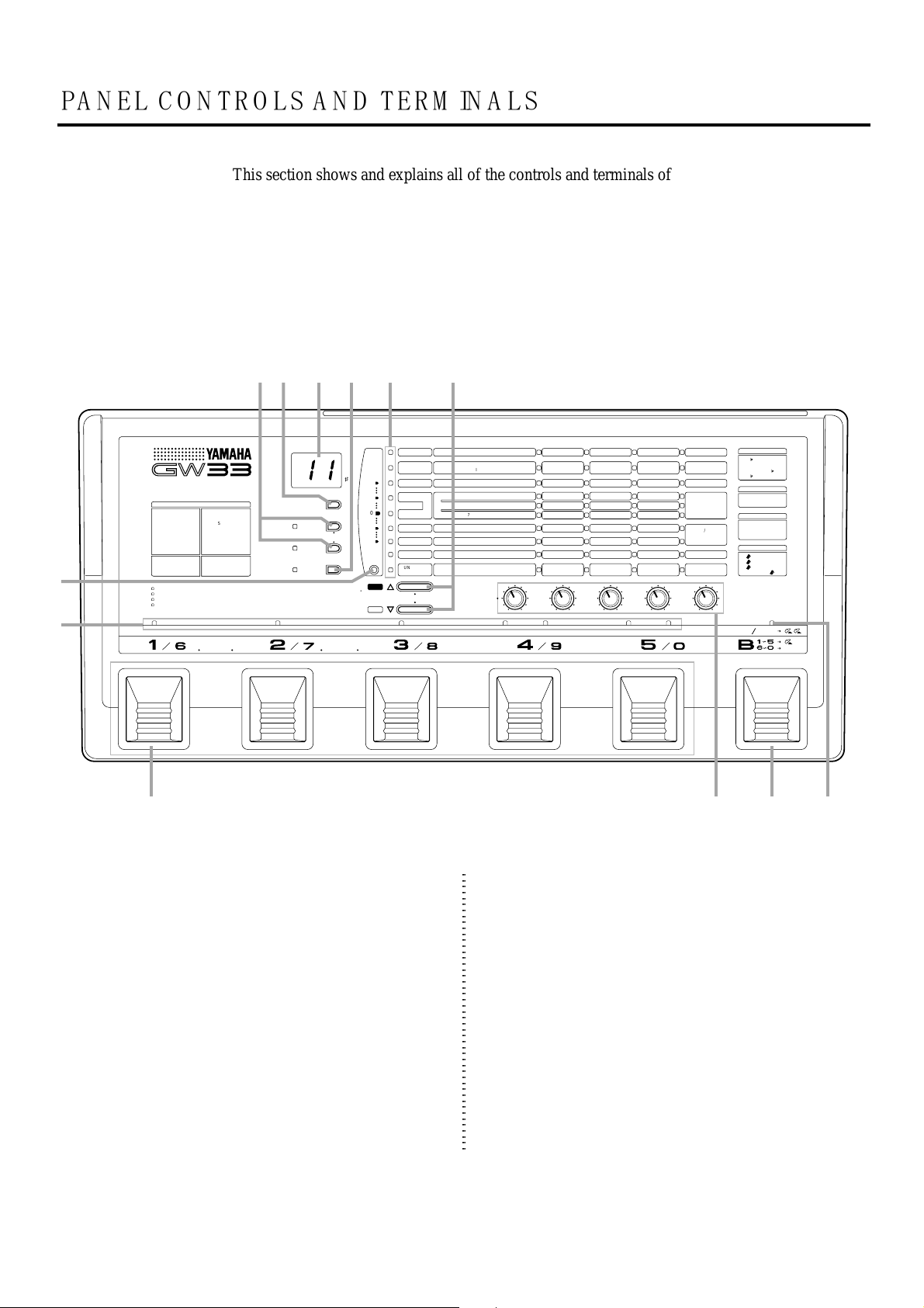
PA N E L C O N T R O L SA N D T E R M IN A L S
This section shows and explains all of the controls and terminals of the GW33. Since the explanations below are fairly brief, you should turn to the page references given for more information
on individual buttons and features. Refer to this section also as necessary when using the GW33,
when you need specific information on a certain control or terminal.
■ TOP PANEL
ewq r t y
BANK MEMORY
PLAY
COPY
METRONOME
SWAP/
WRITE
EDIT/
COMPARE
•••••••
•
•
•
••••
•
•
•
••••••••••
BYPASS
••
+20
+ 5
0
– 5
–20
TUNER
••••••
YES
•
•
•
•
•
•
•
•
•
•
•
•
•
•
•
•
•
•
•
•
••••••
NO
u
i
GUITAR PERFORMANCE EFFECTOR
DISTORTION / INSERT
1 OVERDRIVE
2 DISTORTION
3 DISTORTION
4 OD + DIST
5 OD + DIST
TWIN DRIVE OVERDRIVE & DISTORTION
DUAL MODULATION WITH AURAL EXCITER
INTEGRATED INSERTION LOOP
BUILT-IN TUNER & METRONOME
→INSERT
6
OD
DS
7
1→INSERT
8
2→INSERT
DS
1
9
INSERT→OD
10
1
INSERT→DS
11
INSERT→DS
2
1
2
2
12 INSERT
••••
•
•
•
•
•
•
•
•
•
•
•
•
•
•
•
•
•
•
•
•
•••
•
•
•
•
•
•
•
•
•
•
•
•
•
•
•
•
•
•
•
•
•
•
•
•
•
•
•
•
•
•
•
•
•
•
•
•
•
•
•
•
•
•
•
•
•
•
••••••••••••••••••••••••••••••••••••••••••••••••••••••••••••••••••••
COMPRESSOR DIST / INSERT EQ / AMP MOD 1 MOD 2 DELAY REVERB
••••••••••
TUNER
••
o !1!0 !2
q COPY, SWAP/WRITE Buttons
These two buttons call up the Copy and Swap/Write
operations, respectively. (See pages 32 and 33.) Copy
and Swap are called up from the Play mode, while
Write is called up from the Edit mode. The COPY and
SWAP/WRITE lamps are lit when the respective Copy
or Swap/Write operation is active.
When pressed together simultaneously, these buttons
start the built-in Metronome function. When the
Metronome is on, the lamps of the two buttons flash in
time with the audio click. (See page 35.)
COMP
————---
DIST /
INSERT
EQ / AMP
MOD 1
MOD 2
DELAY
REVERB
N.GATE/UTIL
TUNER/
METRONOME
OD, DIST1,2 (DI*+AN) 4,5 OD*+DIST1,2
1~3
6~11 OD, DIST1,2+INSERT 12 INSERT
1 EQ / 2 STACK 3 COMBO 4 TUBE
1 CHORUS / 2 FLANGER 3 PHASER
4 PITCH SHIFT / 5 DETUNE
6 EXCITER / 7 TOUCH WAH 8 PEDAL WAH
————---
1 HALL 2 ROOM 3 STAGE 4 PLATE
————---
TUNING PITCH
(0~5
=
•
COPY / SWAP / WRITE
PARAM
•
•
•••••••••••••••••••••••••••••••••••••••••••••••••
••••••••••••••••••••••
•
•
•
CHECK
440~445Hz)
MEMORY NO.
ATTACK
PRE-DRIVE*
LOW / —
SPEED
PITCH / PITCH L
ENHANCE / SENSE
THRESHOLD
ABCDE
SENSE
DRIVE
MID / —
DEPTH
— / PITCH R
FREQUENCY
TIME
TIME
—
FB
TONE
VOLUME POSITION
BEAT
(14~88 = 1/4~8/8)
w PLAY Button
Enables the Play mode, from which the effect programs
can be selected and played.
e BANK/MEMORY Indicator
Displays the program number. During Tuner operation,
this displays the name of the note or string played. (See
page 34.) The LED dot (#) at the bottom right serves as
a sharp indicator during Tuner operation (functioning
along with the note name shown in the BANK/
MEMORY indicator), and lights to indicate values of
100 and higher.
—
TONE
HIGH / TONE
TONE / FB
MIX
MIX / RANGE
MIX
MIX
MINIMUM VOLUME
TEMPO
(60~86.=60~186)
LEVEL
LEVEL
LEVEL
ON/OFF
(SWITCH 4)
ON/OFF
(SWITCH 5)
TOTAL LEVEL
CLICK LEVEL
(1 LO 2 MID 3 HI)
PITCH SHIFT
±1 = 3rd
±5 = 5th
±2 = 3rd
±6 = 6th
±3 = 4th
±7 = 7th
±4 = 5th
±8 =
DELAY TIME
10 ~ 90 = 10 ~ 90ms
10.~ 81.=
100 ~ 810ms
ON / OFF
1 EFFECT OFF
2 EFFECT ON
3 SWITCH
VOLUME POSITION
1 DIST
2 DELAY
3 REVERB
4 REVERB
ON OFF
OCTAVE
HOLD
4
1
1
1
1
1
1
1
1
1
1
1
1
1
1
1
1
1
1
1
1
1
1
1
1
1
1
1
1
1
1
1
1
1
1
1
1
1
1
1
1
1
1
1
1
1
1
1
1
1
1
1
1
1
1
1
1
1
1
1
1
1
1
1
1
1
1
1
1
1
1
1
1
1
1
1
1
1
1
1
1
1
1
1
1
1
1
1
1
1
1
1
1
1
1
1
1
1
1
1
1
1
1
1
1
1
1
1
1
1
1
1
1
1
1
1
1
1
1
1
1
1
1
1
1
1
1
1
1
1
1
1
1
1
1
1
1
1
1
1
1
1
1
1
1
1
1
1
1
1
1
1
1
1
1
1
1
1
1
1
1
1
1
1
1
1
1
1
1
1
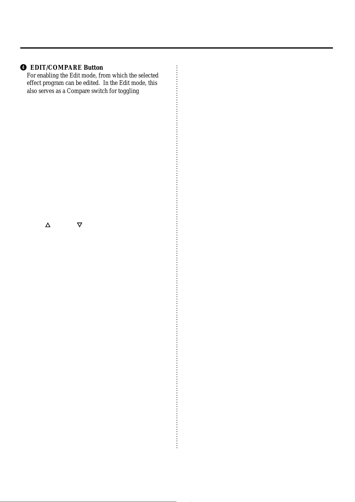
r EDIT/COMPARE Button
For enabling the Edit mode, from which the selected
effect program can be edited. In the Edit mode, this
also serves as a Compare switch for toggling between
the newly edited settings and original settings of an
effect program.
t Effect Parameter/Tuner Lamps
In the Edit mode:
These indicate the effect block and
parameters currently selected for editing. (See
page 13.)
In the Play mode:
These indicate the effect block
currently selected for checking parameter
values. (See page 19.)
In the Tuner mode:
These indicate whether the input
signal is in tune or not; when the center lamp (to
the right of 0) flashes, the signal is in tune. (See
page 34.)
y YES/
In the Edit mode:
and NO/ Buttons
These are used to select an effect
block (and its parameters) for editing. (See page
13.)
When pressed together (in the Edit mode):
These call
up the Parameter Check mode, for checking the
currently edited parameter values. (See page
19.) Pressing one of the buttons again returns to
normal editing.
In the Play mode:
These are used to select the effect
block for checking parameter values. (See page
19.)
In the Copy, Swap and Write operations:
These are
used to execute (YES) or cancel (NO) the
respective operation.
u TUNER Button
For enabling the Tuner mode (from the Play mode).
(See page 34.) Pressing the button again returns to the
Play mode.
i Effect Block ON/OFF Lamps
These light when the corresponding effect block is on.
o Pedal Switches 1 – 5
In the Play mode:
When the ON/OFF lamp (above
Pedal Switch B) is off, these are used to select
effect programs. (See page 12.)
In the Edit or Play modes:
When the ON/OFF lamp
(above Pedal Switch B) is flashing, these are
used to turn individual effect blocks on or off.
(See page 17.)
Also, pressing Pedal Switches 1 and 2 together simultaneously enables the Tuner mode. (See page 34.)
Pressing Pedal Switches 2 and 3 together simultaneously enables the Bypass function. (See page 17.)
!0 Parameter Dials
For selecting the effect type and adjusting the parameters of a selected effect. The parameters in a single
column correspond to the dial in that column.
!1 Pedal Switch B (Bank)
In the Play mode:
Pressing this once enables selection
of banks 1 – 5. Holding this down enables
selection of banks 6 – 0.
Pressing this twice quickly enables effect block on/off
switching. (See page 17.)
!2 ON/OFF Mode Lamp
This flashes to indicate that Pedal Switches 1 – 5 can be
used to turn individual effect blocks on or off.
5
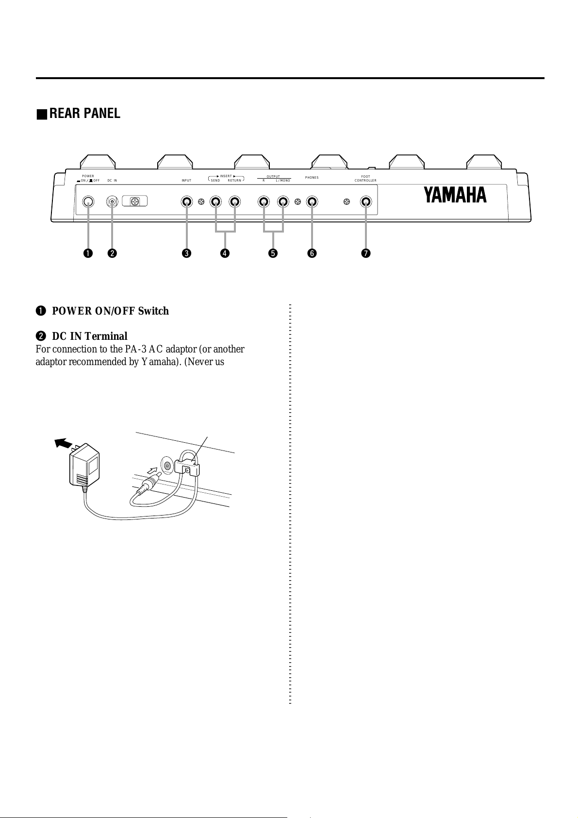
■ REAR PANEL
POWER
ON OFF DC IN INPUT SEND RETURN
INSERT
q w e r y ut
q POWER ON/OFF Switch
w DC IN Terminal
For connection to the PA-3 AC adaptor (or another
adaptor recommended by Yamaha). (Never use the
PA-3B.) Wrap the adaptor cord firmly around the cable
clip as shown, to prevent accidental unplugging of the
power cord during use.
AC adaptor
DC IN
Cable clip
R
OUTPUT
L / MONO
PHONES
FOOT
CONTROLLER
t L/MONO and R OUTPUT Jacks
For stereo or mono output of the instrument and metronome sound. Connect both of these to the corresponding
left and right channels of your stereo amplification system
to take full advantage of the stereo effects of the GW33.
For mono operation, connect your system only to the L/
MONO jack; this provides a mono mix of the instrument
sound when the R OUTPUT jack is not connected.
y PHONES Jack
For stereo output of the guitar/effect and metronome
sound to a set of stereo headphones.
e INPUT Jack
For connection of an instrument (guitar, bass, etc.). (See
page 10 for more information on input/output connections.)
r INSERT SEND and RETURN Jacks
For connection of an external effect device or devices.
Use the SEND jack to output the signal from the GW33,
and use RETURN to input the signal from the external
effect device(s).
u FOOT CONTROLLER Jack
For connection of an optional foot controller (use ONLY
the Yamaha FC7), for controlling the volume or the Pedal
Wah effect. (See page 30.)
6
1
1
1
1
1
1
1
1
1
1
1
1
1
1
1
1
1
1
1
1
1
1
1
1
1
1
1
1
1
1
1
1
1
1
1
1
1
1
1
1
1
1
1
1
1
1
1
1
1
1
1
1
1
1
1
1
1
1
1
1
1
1
1
1
1
1
1
1
1
1
1
1
1
1
1
1
1
1
1
1
G W 33SY ST E M O V E R V IE W
1
1
1
1
1
1
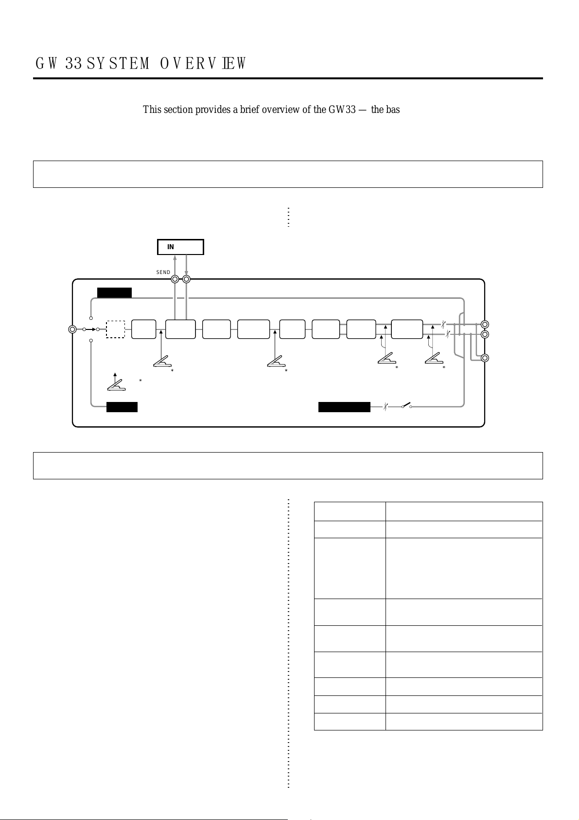
This section provides a brief overview of the GW33 — the basic structure of its various functions
and the memory system. Once you gain a general understanding of the internal workings of the
GW33 as given here, you’ll have the tools for taking full advantage of its features.
GW33 Internal Structure
The diagram below shows the internal system of the
effects and other functions of the GW33.
INSERT
INSERT
SEND
INSERT
RETURN
BYPASS
MOD 1, 2 Block
Volume
Pedal
(Position 1)
DIST /
INSERT
N.GATE EQ / AMP DELAY MOD 1 REVERB
INPUT
WAH
(when
Touch Wah
or Pedal
Wah is
selected)
Wah
Pedal
COMP
TUNER
The Effects of the GW33
The GW33 is equipped with a comprehensive set of
effects designed specifically for the guitar player. Up to
eight different effects can be used simultaneously. Moreover, a special Insert block lets you connect additional
external effect units to the multi-effect chain of the GW33.
Individual effects (excepting Noise Gate) can be turned on
and off as needed with the Pedal Switches and can be
quickly and easily adjusted with the Parameter Dials.
There are eight main effect blocks and a total of thirty-one
different effect types:
(Refer to the EFFECTS AND PARAMETERS section,
page 20, for more detailed descriptions and explanations
of these effects.)
With all these various effects, used individually or simultaneously, the GW33 has all you need to augment your
sound, whatever the application. Plus, flexible effect
bypass (on/off) functions give you even more realtime
control over the sound. A programmable Noise Gate is
also included for filtering out hum, hiss and other undesirable noise. (See page 29.)
Volume
Pedal
(Position 2)
MOD 2
METRONOME
* Use the optional YAMAHA Foot Controller FC7.
Effect Block
Compressor
Distortion/Insert
Equalizer/
Amp Simulator
Modulation 1
Modulation 2
Delay
Reverb
Noise Gate
TOTAL
LEVEL
OUTPUT
L/MONO
R
Headphones
Volume
Pedal
(Position 3)
CLICK
LEVEL
Volume
Pedal
(Position 4)
Effect Type
Compressor
Overdrive, Distortion 1,
Distortion 2, Overdrive + Distortion 1,
Overdrive + Distortion 2, Overdrive → Insert,
Distortion 1 → Insert, Distortion 2 → Insert,
Insert → Overdrive, Insert → Distortion 1,
Insert → Distortion 2, Insert
Equalizer, Stack Amp Simulator,
Combo Amp Simulator, Tube Amp Simulator
Chorus, Flanger, Phaser, Pitch Shift,
Detune, Exciter, Touch Wah, Pedal Wah
(Same as Modulation 1; effects can be used
independently.)
Delay
Hall, Room, Stage, Plate
Noise Gate
7
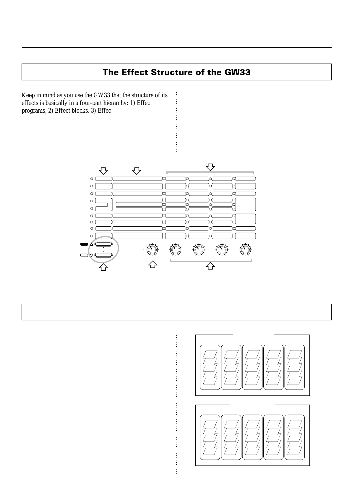
The Effect Structure of the GW33
Keep in mind as you use the GW33 that the structure of its
effects is basically in a four-part hierarchy: 1) Effect
programs, 2) Effect blocks, 3) Effect types, and 4) Effect
parameters.
An effect program consists of eight different effect blocks,
all of which can be used simultaneously. A block includes
•••••
••••••
•
•
•
•
•
•
•
•
•
•
•
•
•
•
•
•
•
•
•
•
••••••
YES
NO
Effect Block
COMP
DIST /
INSERT
EQ / AMP
MOD 1
MOD 2
DELAY
REVERB
N.GATE/UTIL
TUNER/
METRONOME
•
•
•
••••••••••••••••••••••
•
•
•
Effect Types
————---
OD, DIST1,2 (DI*+AN) 4,5 OD*+DIST1,2
1~3
6~11 OD, DIST1,2+INSERT 12 INSERT
1 EQ / 2 STACK 3 COMBO 4 TUBE
1 CHORUS / 2 FLANGER 3 PHASER
4 PITCH SHIFT / 5 DETUNE
6 EXCITER / 7 TOUCH WAH 8 PEDAL WAH
————---
1 HALL 2 ROOM 3 STAGE 4 PLATE
————---
TUNING PITCH
(0~5
=
440~445Hz)
PARAM
COPY / SWAP / WRITE
•••••••••••••••••••••••••••••••••••••••••••••••••
CHECK
MEMORY NO.
ABCDE
ATTACK
PRE-DRIVE*
LOW / —
SPEED
PITCH / PITCH L
ENHANCE / SENSE
TIME
TIME
THRESHOLD
—
one or more effect types, one of which can be used at a
time. And each effect type has up to four different parameters, which allow you to set the sound of the effect. The
logic of this structure is reflected in the panel layout, with
effect blocks, types and parameters printed in a matrix
from left to right.
Effect Parameters
SENSE
DRIVE
MID / —
DEPTH
— / PITCH R
FREQUENCY
FB
TONE
VOLUME POSITION
BEAT
(14~88 = 1/4~8/8)
—
TONE
HIGH / TONE
TONE / FB
MIX
MIX / RANGE
MIX
MIX
MINIMUM VOLUME
TEMPO
(60~86.=60~186)
LEVEL
LEVEL
LEVEL
ON/OFF
(SWITCH 4)
ON/OFF
(SWITCH 5)
TOTAL LEVEL
CLICK LEVEL
(1 LO 2 MID 3 HI)
These are used to
select the effect
block.
This is used to
select the
effect type.
Memory Structure
The GW33 has a total of 50 effect programs, divided into
ten banks of five programs each. The 25 programs from
61 – 05 are Preset programs. Programs 11 – 55 are User
programs, and your own original settings can be stored to
these.
These are used to change the
parameters in the corresponding
columns.
User Programs
Bank 1 Bank 2 Bank 3 Bank 4 Bank 5
11
12
13
14
15
21
22
23
24
25
Preset Programs
Bank 6 Bank 7 Bank 8 Bank 9 Bank 0
61
62
63
64
65
71
72
73
74
75
31
32
33
34
35
81
82
83
84
85
41
42
43
44
45
91
92
93
94
95
51
52
53
54
55
01
02
03
04
05
8

Effect Programs
Sound Character
#
Main Sub
Dist
11
Hard
Dist
12
Hard
Dist
13
Softer
Over
14
Drive
15
Clean
Dist
21
Hard
Dist
22
Hard
Over
23
Drive
24
Clean
25
Clean
Dist
31
Hard
Dist
32
Hard
Over
33
Drive
34
Clean
35
Clean
Dist
41
Hard
Dist
42
Hard
Over
43
Drive
44
Clean
45
Clean
Dist
51
Hard
Dist
52
Softer
53
Clean
54
S.E.
55
S.E.
—
—
Detune
—
Chorus
Detune
—
Touch
Wah
Pitch
Detune
Chorus
Detune
—
Flanger
—
—
Phaser
Detune
—
Detune
—
Detune
Chorus
Pitch
Pedal
Wah
Detune
Pedal Wah
Flanger
Touch Wah
Chorus
Phaser
Programmer’s comments
Distortion especially for rock solos.
Digital + analog distortion, plus EQ,
for heavy metal.
Detune and reverb for a “wet” solo
sound.
Natural, warm overdrive.
Clean, spacious sound with Cho./
Detune/Delay/Reverb mix.
Hard, metallic lead.
Dynamically responds to your
plucking technique.
Stereo pitch shift: 5th above and
below.
Clean and dreamy with long delay.
Soft, clean sound, ideal for soloing or
rhythmic chords.
Analog overdrive + distortion —
hard-edged for backing.
Analog + digital distortion, plus
flanger and delay.
Bright overdrive with delay for
American hard rock leads.
British 60’s rock sound — simple
and straight.
70’s fusion sound, with heavy
phaser.
Hard distortion for rock soloing.
Slightly bright distortion for hard
rock backing.
Crunch sound with enhanced low
and high frequencies.
Good, clear sound for rhythmic
playing.
Ideal for funky rhythmic playing or
arpeggios.
Hard distortion sound, with pitch an
octave below.
Hard crunch sound for rhythmic
playing; with Pedal Wah.
Mellow sound for rhythmic play.
Sound effect with dynamic response
to plucking technique.
Chorus sound with stereo phaser.
Sound Character
#
Main Sub
Dist
61
Hard
Dist
62
Hard
Over
63
Drive
Clean
64
Clean
65
Dist
71
Hard
Dist
72
Hard
Over
73
Drive
Clean
74
Clean
75
Over
81
Drive
Dist
82
Hard
Dist
83
Softer
Clean
84
Clean
85
Dist
91
Hard
Dist
92
Hard
Over
93
Drive
Clean
94
Clean
95
Dist
01
Hard
Dist
02
Hard
Over
03
Drive
Clean
04
Clean
05
—
Detune
—
Detune
Flanger
Chorus
—
Wah
Chorus
Detune
Phaser
—
Detune
—
Detune
Phaser
Flanger
Detune
Detune
—
—
Touch
Wah
—
—
—
Detune
Chorus
Programmer’s comments
Digital and analog distortion for rock
solos.
Analog overdrive + distortion; good
for pop music.
Natural overdrive for rock’n’roll.
Clean sound, good for wide range of
styles (ex., blues, funk, jazz).
Clear sound with flanger and chorus.
Heavy distortion sound with en-
hanced low and high frequencies.
Distortion sound for backing.
Spacious overdrive sound for fusion.
Natural reverb sound from the 50’s.
Dynamics “squashed” with compression.
Tremolo sound.
Digital + analog overdrive for rock
or fusion.
Powerful sound, good for rock
ballads.
Overdrive sound for rock leads.
Mellow, round sound.
Clean sound for rhythmic play.
Hard distortion sound with enhanced
attack; for rock leads.
Distortion sound with detuning, for
rock backing.
“Dry” overdrive.
Multi-purpose program for a wide
variety of styles.
Touch Wah program, good for funk,
jazz, blues, etc.
Hard digital + analog distortion
sound for direct recording.
Hard distortion program, with stack
amp sound, for direct recording.
Warm overdrive sound for direct
recording.
Clear, distinct sound with detuning
and delay, for direct recording.
Clean sound for direct recording.
9
GUIDED TOUR
When using your GW33 for the first time, read through this short section of the
manual. It guides you step-by-step in all basic operations: setting the instrument
up, connecting it properly to other equipment, and playing the effect programs.
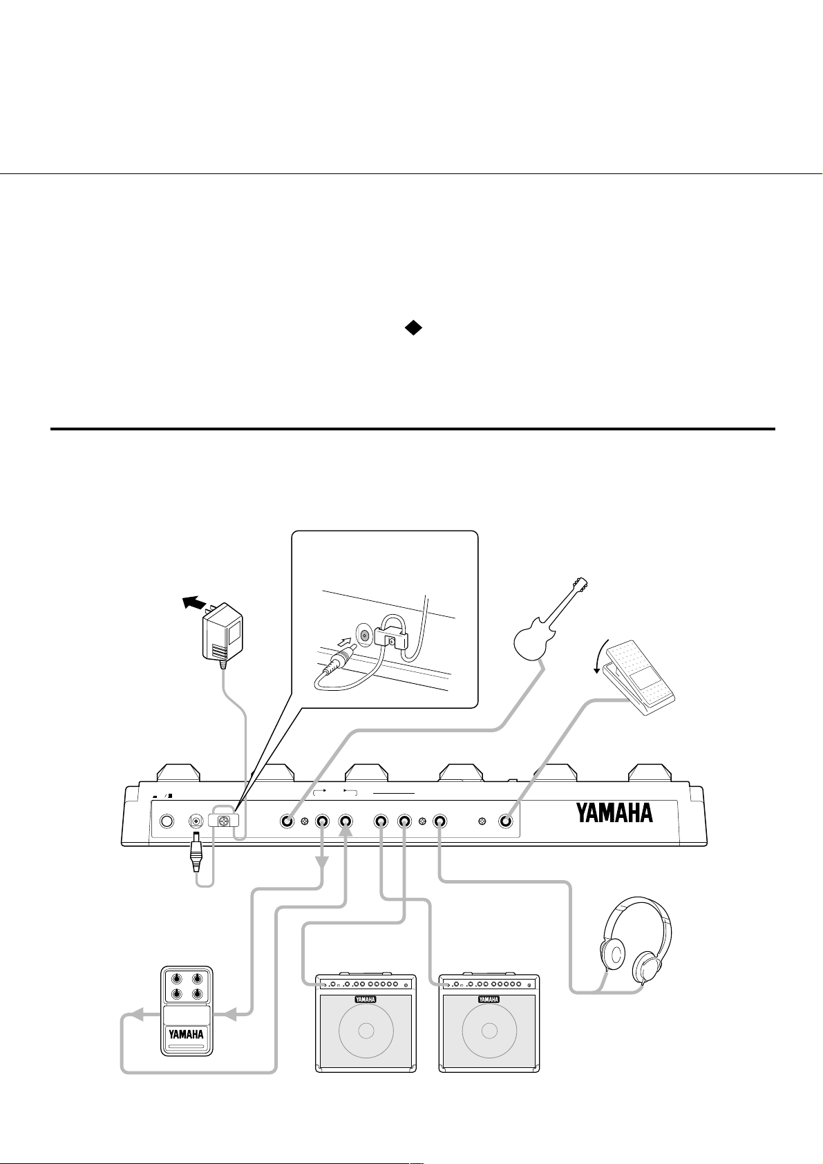
SE T T IN G U PA N D PL A Y IN G Y O U R G W 33
Once you’ve taken your GW33 out of the box and are ready to use it, you’ll have to make a few
connections and follow some simple instructions on setting it up.
Plug into a
suitable AC
outlet
PA-3
power adaptor
Use only this
adaptor or
another Yamaha
recommended
adaptor.
POWER
ON OFF DC IN INPUT SEND RETURN
External effect unit
Wrap the adaptor cord around the
cable clip to prevent accidintal
unplugging.
DC
IN
INSERT
Guitar amplifier
(left channel)
R
OUTPUT
L / MONO
PHONES
Electric guitar
FOOT
CONTROLLER
Guitar amplifier
(right channel)
Optional FC7
Foot Controller
(for Volume pedal
and Pedal Wah
control).
Headphones
OUT IN
10
When using a single guitar amp, connect to
*
the L/MONO OUTPUT jack.
Signals are output through
*
the OUTPUT jacks, even
when headphones are
connected.
*
Adjust the headphone
volume with the Total Level
parameter (see page 31).
1
1
1
1
1
1
1
1
1
1
1
1
1
1
1
1
1
1
1
1
1
1
1
1
1
1
1
1
1
1
1
1
1
1
1
1
1
1
1
1
1
1
1
1
1
1
1
1
1
1
1
1
1
1
1
1
1
1
1
1
1
1
1
1
1
1
1
1
1
1
1
1
1
1
1
1
1
1
1
1
1
1
1
1
1
1
1
1
1
1
1
1
1
1
1
1
1
1
1
1
1
1
1
1
1
1
1
1
1
1
1
1
1
1
1
1
1
1
1
1
1
1
1
1
1
1
1
1
1
1
1
1
1
1
1
1
1
1
1
1
1
1
1
1
1
1
1
1
1
1
1
1
1
1
1
1
1
1
1
1
1
1
1
1
1
1
1
First, make sure that the power switch on the GW33
is off before making ANY connections.
2
Plug the DC output cable from the supplied PA-3
adaptor (or another adaptor recommended by
Yamaha) (Never use the PA-3B.) into the DC IN
terminal on the rear panel, then plug the adaptor into
a convenient AC outlet.
The cable clip located next to this terminal helps to
prevent accidental unplugging of the power supply
during use. Wrap the adaptor cord firmly around the
clip (see the Rear Panel illustration, page 10).
CAUTION! ■
AC adaptor with the GW33. (See the precaution
U SE T H E C O R R EC T PO W E R S U PP L Y
3
Plug your instrument into the INPUT jack on the rear
Do not attempt to use a different
on page 3.)
panel.
For the sake of these instructions, we’ll assume
you’re using an electric guitar; however, most any
electronic instrument can be used.
NOTE ■
a synthesizer or electronic keyboard. Since their
output level is generally much higher than that of a
guitar, the volume control on the instrument should
be turned down accordingly.
4
Connect the GW33 output or outputs to your ampli-
You should be careful if you are connecting
fier/speaker system, as shown on page 10. Before
you do this, however, make sure that the power on
the system is first turned off and all volume controls
are set to zero — this includes the guitar controls and
the volume on the connected amp(s).
NOTE ■
best results.
5
If you are using an optional FC7 Foot Controller
Use the clean channel of the amplifier for
with the GW33, connect it to the FOOT CONTROLLER input jack on the rear panel. Make sure that the
pedal is at or near the maximum position.
6
Turn on the power of all the equipment, starting with
the GW33, and turning on the connected amplifier
last.
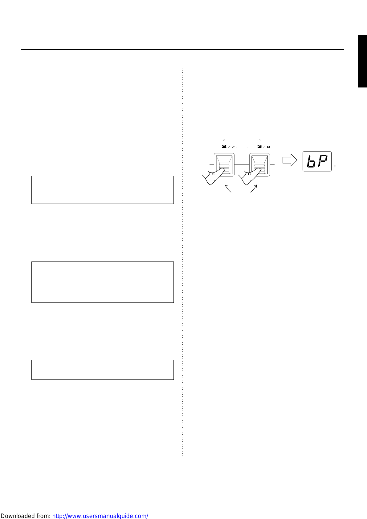
7
Before you turn up the volume and try to play, set all
the effects to off by using the Bypass function.
To do this, simultaneously press and hold down
Pedal Switches 2 and 3. Keep holding them down
(for roughly one second) until “bP” (Bypass)
appears in the BANK/MEMORY indicator.
DIST / INSERT EQ / AMP
••••••••••
BYPASS
••
Firmly press and hold these
down for about one second.
BANK MEMORY
This temporarily turns off all effect processing, and
lets you hear the “dry” input signal.
8
Now, set your guitar to a suitable volume. Next,
slowly bring up the level of the connected amplifier
as you play, until the level is suitable.
9
Finally, turn the Bypass function off by pressing any
one of the Pedal Switches (1 – 5 or B).
If you’ve followed all these instructions carefully,
you should now be able to hear the sound of your
guitar processed by the effects of the GW33, and are
able to try out some of the other effect programs of
the GW33. If no sound is output or the sound isn’t as
you expect, refer to the Troubleshooting section on
page 36.
•••••••
11
PL A Y IN G W IT H T H E E FFE C T S
Now that you’ve set up your GW33 and have got sound out of it, let’s try playing with some of
the effects. (If you haven’t already done so, read through the GW33 SYSTEM OVERVIEW
section on page 7 for information on the basic structure of the GW33.)
1
First, make sure that the Play mode is enabled. Press
p.
PLAY
To change the bank, use the Bank (B) Pedal Switch.
To select one of banks 1 – 5, press it once, then press
the appropriate Pedal Switch 1 – 5.
1 – 5
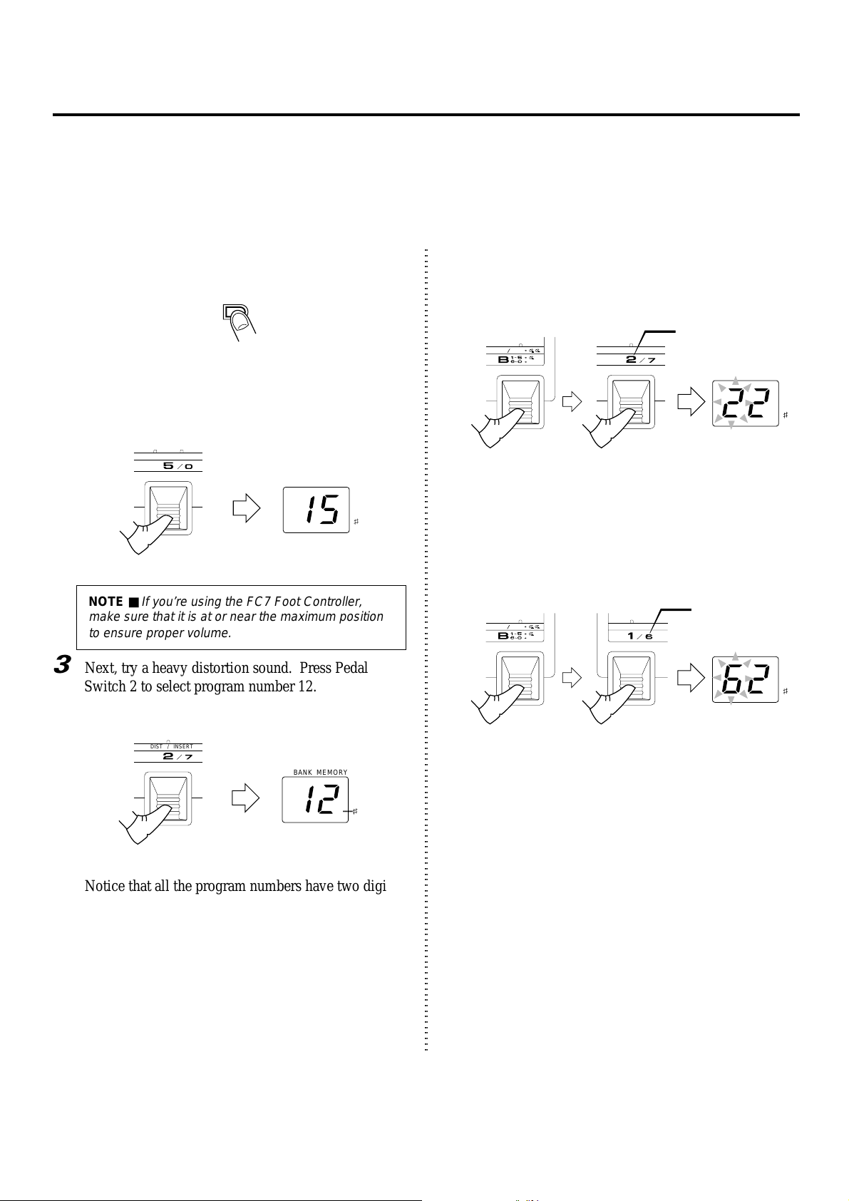
2
Let’s start with a clean chorus/delay effect. Use
Pedal Switch 5 to select program number 15.
DELAY REVERB
BANK MEMORY
NOTE ■
If you’re using the FC7 Foot Controller,
make sure that it is at or near the maximum position
to ensure proper volume.
3
Next, try a heavy distortion sound. Press Pedal
Switch 2 to select program number 12.
DIST / INSERT
BANK MEMORY
ON OFF
HOLD
Press this once... ...then press one
•••••••
To select one of banks 6 – 0, hold the Bank Pedal
DIST / INSERT
BANK MEMORY
•••••••
of these to select
bank 1 – 5.
Switch down and simultaneously press the appropriate alternate numbered Pedal Switch 6 – 0.
6 – 0
ON OFF
HOLD
While holding
this down...
COMPRESSOR
BANK MEMORY
•••••••
...press one of
these to select
bank 6 – 0.
Notice that all the program numbers have two digits.
The first digit indicates the bank and the second
indicates the program number. By pressing one of
the Pedal Switches 1 – 5, you can select one of five
programs in the currently selected bank.
12
4
•••••••
Now that you know how to select banks and programs, try exploring some of the other effect programs of the GW33. Look through the Effect
Programs list on page 9 for more information about
the programs, and play with a few of them to hear
how they sound.
 Loading...