

Yamaha Audio GF24/12, GF16/12, GF12/12 User Manual
MIXING CONSOLE
Owner’s Manual
Keep This Manual For Future Reference.
E

WARNING: THIS APPARATUS MUST BE EARTHED
IMPORTANT
THE WIRES IN THIS MAINS LEAD ARE COLOURED IN
ACCORDANCE WITH THE FOLLOWING CODE:
GREEN-AND-YELLOW : EARTH
BLUE : NEUTRAL
BROWN : LIVE
As the colours of the wires in the mains lead of this apparatus may
not correspond with the coloured markings identifying the terminals in
your plug, proceed as follows:
The wire which is coloured GREEN and YELLOW must be
connected to the terminal in the plug which is marked by the letter E
or by the safety earth symbol or coloured GREEN and YELLOW.
The wire which is coloured BLUE must be connected to the terminal
which is marked with the letter N or coloured BLACK.
The wire which is coloured BROWN must be connected to the
terminal which is marked with the letter L or coloured RED.
* This applies only to products distributed by YAMAHA KEMBLE
MUSIC (U.K.) LTD.

Precautions
Warnings
• Do not allow water to enter this unit or allow the
unit to become wet. Fire or electrical shock may
result.
• Connect this unit’s power cord only to an AC outlet of the type stated in this Owner’s Manual or as
marked on the unit. Failure to do so is a fire and
electrical shock hazard.
• Do not scratch, bend, twist, pull, or heat the power
cord. A damaged power cord is a fire and electrical
shock hazard.
• Do not place heavy objects, including this unit, on
top of the power cord. A damaged power cord is a
fire and electrical shock hazard. In particular, be
careful not to place heavy objects on a power cord
covered by a carpet.
• If you notice any abnormality, such as smoke,
odor, or noise, or if a foreign object or liquid gets
inside the unit, turn it off immediately. Remove
the power cord from the AC outlet. Consult your
dealer for repair. Using the unit in this condition is
a fire and electrical shock hazard.
• Should this unit be dropped or the cabinet be
damaged, turn the power switch off, remove the
power plug from the AC outlet, and contact your
dealer. If you continue using the unit without
heeding this instruction, fire or electrical shock
may result.
• If the power cord is damaged (i.e., cut or a bare
wire is exposed), ask your dealer for a replacement.
Using the unit with a damaged power cord is a fire
and electrical shock hazard.
• Do not remove the unit’s cover. You could receive
an electrical shock. If you think internal inspection, maintenance, or repair is necessary, contact
your dealer.
• Do not modify the unit. Doing so is a fire and electrical shock hazard.
Precautions
Cautions
• This unit has ventilation holes at the top and right
side to prevent the internal temperature rising too
high. Do not block them. Blocked ventilation holes
are a fire hazard.
• Hold the power cord plug when disconnecting it
from an AC outlet. Never pull the cord. A damaged
power cord is a potential fire and electrical shock
hazard.
• Do not touch the power plug with wet hands.
Doing so is a potential electrical shock hazard.
Operating Notes
• Using a mobile telephone near this unit may
induce noise. If noise occurs, use the telephone
away from the unit.
• XLR-type connectors are wired as follows:
pin 1: ground, pin 2: hot (+), and pin 3: cold (–).
• Insert TRS phone jacks are wired as follows:
sleeve: ground, tip: send, and ring: return.
• The performance of components with moving
contacts, such switches, rotary controls, faders,
and connectors, deteriorates over time. The rate of
deterioration depends on the operating environment and is unavoidable. Consult your dealer
about replacing defective components.
3
—Owner’s Manual

Introduction
4
Introduction
Thank you for purchasing the Yamaha GF24/12, GF16/12, or GF12/12 mixing console.
These mixers provide an ample twelve outputs, and are suitable for a wide variety of
applications ranging from concert sound reinforcement to installed systems. In order to
take full advantage of the mixer’s functionality and to enjoy years of trouble-free performance, please read this manual carefully.
Note:
• This owner’s manual assumes that you are familiar with basic operation of a mixing
console and its specialized vocabulary.
• At points where the specifications of the GF24/12, GF16/12, and GF12/12 differ, the
specifications of the GF16/12 and GF12/12 are given in curly brackets { }.
Features of the system
• In addition to the main stereo outputs, this mixer
provides six AUX outputs plus four group outputs
(a total of 12 outputs). The AUX/GROUP outputs
can be used not only as sends to external effect
processors or to a multitrack recorder, but are also
ideal for creating separate foldback mixes for each
speaker and amp.
• The MONO OUT jack can be controlled independently from the STEREO OUT jacks. Since a monaural mix of the main output is sent from this
output, it can be used to extend a PA system.
• All input channels provide a high-pass filter, a
three-band EQ, and 60 mm faders.
• All input channels/AUX returns provide a PFL
switch, and AUX/group/stereo output channels
provide an AFL switch. You can audition input and
output sources at the touch of a button.
• All mono input channels provide balanced XLR
type and TRS phone jack connectors that accommodate a range of sources from mics to line level
devices.
• Switchable phantom power is provided. This can
supply DC +48 V power from the XLR type input
connectors to condenser mics and direct boxes
that require an external power supply.
• Two stereo input channels allow connection of
line-level equipment. 1/4" phone jack and phono
jack inputs can be selected by a switch.
• Two stereo AUX returns are provided. This allows
AUX return signals to be sent to an AUX bus or
GROUP bus as well as to the ST bus. These can
also be used as spare line level input jacks.
• An insert I/O jack is provided on each mono input
channel and on the ST bus, allowing you to insert
external effect processors as desired.
• The TAPE IN jacks and REC OUT jacks let you
easily connect a master recorder for recording or
playback.
Contents
Front and rear panel ....................... 5
Channel controls..................................6
Master controls ..................................10
Connectors ........................................17
Specifications................................ 21
General specifications.........................21
Input specifications ............................22
Output specifications .........................22
Dimensions ........................................23
Block/Level Diagram ..........................24
—Owner’s Manual
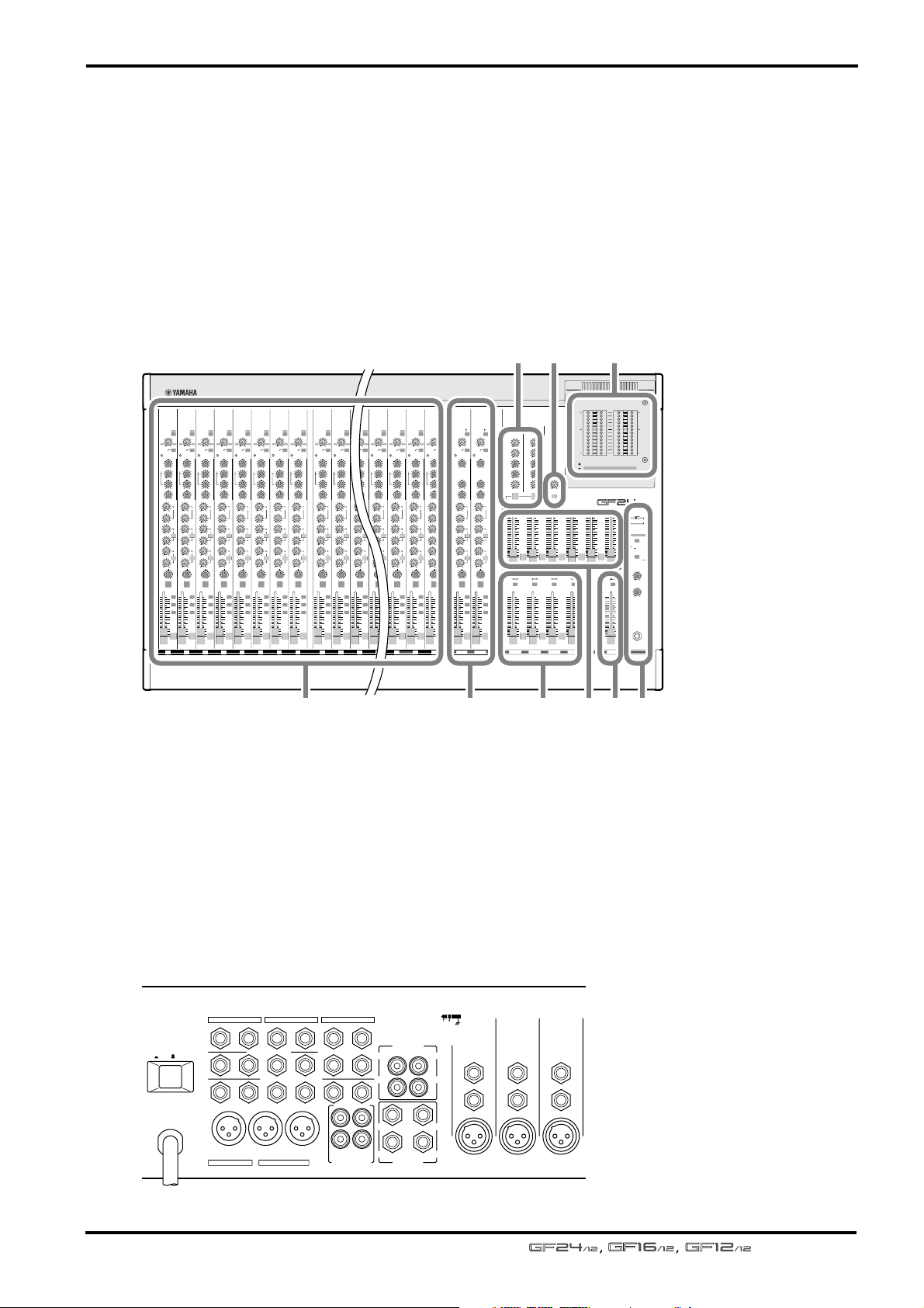
Front and rear panel
This section explains the names and functions of each section of the GF24/12, GF16/12,
and GF12/12.
The functionality of these mixers is grouped into ten sections. These are the two channel control sections, seven master control sections, and the rear panel connectors. Their
functions will be explained sequentially.
Front panel
GAIN
+10
HIGH
MID
LOW
1
2
3
4
5
6
PAN
–15
PEAK
–15 +15
250 5K
–15 +15
–15 +15
010
010
010
010
010
010
1
26dB
26dB
26dB
26dB
26dB
26dB
26dB
26dB
26dB
26dB
GAIN
GAIN
GAIN
GAIN
GAIN
GAIN
GAIN
–34
–34
–34
–34
–34
+10
+10
+10
–60
–60
–60
–15
–15
80
AUX
ON
10
5
0
5
10
15
20
30
40
–15
80
80
PEAK
PEAK
PEAK
HIGH
HIGH
HIGH
–15 +15
–15 +15
–15 +15
MID
MID
MID
250 5K
250 5K
250 5K
–15 +15
–15 +15
–15 +15
LOW
LOW
LOW
–15 +15
–15 +15
–15 +15
AUX
AUX
PRE
PRE
PRE
1
1
1
010
010
010
2
2
2
010
010
010
PRE
PRE
PRE
3
3
3
010
010
010
4
4
4
010
010
010
PRE
PRE
PRE
5
5
5
010
010
010
6
6
6
010
010
010
PAN
PAN
PAN
R
R
R
EVENLODD
EVENLODD
EVENLODD
ON
ON
10
10
1–2
1–2
1–2
5
5
3–4
3–4
3–4
0
0
5
5
ST
ST
ST
10
10
15
15
20
20
30
30
40
40
PFL
PFL
PFL
–34
+10
+10
–60
–60
–60
–15
–15
80
80
80
PEAK
PEAK
HIGH
HIGH
–15 +15
–15 +15
MID
MID
250 5K
250 5K
–15 +15
–15 +15
LOW
LOW
–15 +15
–15 +15
AUX
AUX
AUX
PRE
PRE
PRE
1
1
010
010
2
2
010
010
PRE
PRE
PRE
3
3
010
010
4
4
010
010
PRE
PRE
PRE
5
5
010
010
6
6
010
010
PAN
PAN
R
R
R
EVENLODD
EVENLODD
EVENLODD
ON
ON
ON
10
10
10
1–2
1–2
1–2
5
5
5
3–4
3–4
3–4
0
0
0
5
5
5
ST
ST
ST
10
10
10
15
15
15
20
20
20
30
30
30
40
40
40
PFL
PFL
PFL
HIGH
MID
LOW
1
2
3
4
5
6
PAN
+10
–15
–15 +15
250 5K
–15 +15
–15 +15
010
010
010
010
010
010
GAIN
–34
–34
+10
+10
–60
–60
–15
80
80
PEAK
PEAK
HIGH
HIGH
–15 +15
MID
MID
250 5K
–15 +15
LOW
LOW
–15 +15
AUX
AUX
PRE
PRE
1
1
010
2
2
010
PRE
PRE
3
3
010
4
4
010
PRE
PRE
5
5
010
6
6
010
PAN
PAN
R
R
EVENLODD
EVENLODD
ON
ON
10
10
1–2
1–2
5
5
3–4
3–4
0
0
5
5
ST
ST
10
10
15
15
20
20
30
30
40
40
PFL
PFL
–15
PEAK
–15 +15
250 5K
–15 +15
–15 +15
010
010
010
010
010
010
26dB
GAIN
GAIN
–34
–34
–34
+10
+10
–60
–60
–60
–15
–15
80
80
80
PEAK
PEAK
HIGH
HIGH
–15 +15
–15 +15
MID
MID
250 5K
250 5K
–15 +15
–15 +15
LOW
LOW
–15 +15
–15 +15
AUX
AUX
AUX
PRE
PRE
PRE
1
1
010
010
2
2
010
010
PRE
PRE
PRE
3
3
010
010
4
4
010
010
PRE
PRE
PRE
5
5
010
010
6
6
010
010
PAN
PAN
R
R
R
EVENLODD
EVENLODD
EVENLODD
ON
ON
ON
10
10
10
1–2
1–2
1–2
5
5
5
3–4
3–4
3–4
0
0
0
5
5
5
ST
ST
ST
10
10
10
15
15
15
20
20
20
30
30
30
40
40
40
PFL
PFL
PFL
GAIN
HIGH
MID
LOW
1
2
3
4
5
6
PAN
+10
–15
–15 +15
250 5K
–15 +15
–15 +15
010
010
010
010
010
010
191817111098765432
20
26dB
26dB
26dB
GAIN
GAIN
GAIN
–34
–34
–34
+10
+10
+10
–60
–60
–60
–15
–15
80
PEAK
AUX
PRE
PRE
PRE
EVENLODD
ON
10
1–2
5
3–4
0
5
ST
10
15
20
30
40
PFL
–15
80
80
80
PEAK
PEAK
PEAK
HIGH
HIGH
HIGH
–15 +15
–15 +15
–15 +15
MID
MID
MID
250 5K
250 5K
250 5K
–15 +15
–15 +15
–15 +15
LOW
LOW
LOW
–15 +15
–15 +15
–15 +15
AUX
AUX
AUX
PRE
PRE
1
1
1
010
010
010
2
2
2
010
010
010
PRE
PRE
3
3
3
010
010
010
4
4
4
010
010
010
PRE
PRE
5
5
5
010
010
010
6
6
6
010
010
010
PAN
PAN
PAN
R
R
R
EVENLODD
EVENLODD
ON
ON
ON
10
10
10
1–2
1–2
5
5
5
3–4
3–4
0
0
0
5
5
5
ST
ST
10
10
10
15
15
15
20
20
20
30
30
30
40
40
40
PFL
PFL
20
1918171110987654321
Front and rear panel
5
6379
234
10
10
5
5
0
0
5
5
10
10
15
15
20
20
30
30
40
40
AFL
AFL
MONO
010
POST
10
5
0
5
10
15
20
30
40
AFL
STEREOGROUP 1 GROUP 2 GROUP 3 GROUP 4
PHANTOM +48V
OFF ON
METER SELECT
STEREO PFL•AFL
TAPE IN
010
C-R MONITOR
LEVEL
010
PHONES
LEVEL
PHONES
POWER
PEAK
+8
+5
+3
+1
0
–1
–3
–5
–7
–10
–15
–20
PHANTOM
GROUP
3
0
4
010
3
010
4
010
010
PEAK
+8
+5
+3
+1
0
–1
–3
–5
–7
–10
10
–15
–20
LR LR
STEREO PFL•AFL/TAPE IN
1
010
ON
MIXING CONSOLE
TAPE IN
10
10
10
5
5
5
0
0
0
5
5
5
10
10
10
15
15
15
20
20
20
30
30
30
40
40
40
AFL
AFL
AFL
PAN
PAN
RL
RL
TO ST
RL
TO ST
TO ST
10
10
10
5
5
5
0
0
0
5
5
5
10
10
10
15
15
15
20
20
20
30
30
30
40
40
40
AFL
AFL
AFL
23/24
21/22
A
A
B
B
26dB
GAIN
GAIN
–34
–60
+10 –34
PEAK
HIGH
–15 +15
MID
–15 +15
LOW
–15 +15
PRE
1
010
2
010
PRE
3
010
4
010
PRE
5
010
6
010
BAL
R
EVENLODD
1–2
3–4
ST
PFL
GROUP
GROUP
1
+10 –34
0
10
80
80
PEAK
2
010
HIGH
AUX
AUX
1
–15 +15
010
2
010
MID
–15 +15
LOW
–15 +15
AUX
PRE
1
010
2
010
PRE
3
010
4
010
PRE
5
010
6
010
BAL
R
EVENLODD
ON
ON
10
1–2
5
3–4
0
5
ST
10
15
20
30
40
PFL
23/2421/22
ST
ST
010
PFL PFL
AUX
1 AUX RETURN 2
PRE
10
5
0
PRE
5
10
15
20
30
PRE
40
AFL
AUX 1 AUX 2 AUX 3 AUX 4 AUX 5 AUX 6
PAN
PAN
R
RL
EVENLODD
TO ST
10
10
1–2
5
5
3–4
0
0
5
5
ST
10
10
15
15
20
20
30
30
40
40
AFL
PFL
Channel controls
1. Mono input channels (page 6)
2. Stereo input channels (page 8)
Rear panel
Connectors (page 17)
POWER
ON/ OFF
C-R OUT
MONO OUT
+4dB
GROUP OUT +4dB
+4dBV
ST INSERT I/O
1234
AUX OUT +4dB (BALANCE)
+4dBV
STEREO OUT
0dB
AUX RETURN
(MONO)
2LLRLR
TAPE IN –10dBV
REC OUT –10dBV
+4dB
1L
1R2R
23L
24R
123456
23L
24R
INPUT
(MONO)
INPUT
21 54 8
Master controls
3. GROUP section (page 10)
4. AUX section (page 11)
5. STEREO/MONO section (page 12)
6. AUX RETURN section (page 13)
7. TAPE IN section (page 14)
8. Other controls/connectors (page 14)
9. Meter section (page 16)
INSERT I/O
OUT IN
B
INSERT I/O
INSERT I/O
21L
0dB
22R
INPUT
B
21L
22RRRLL
INPUT
A
A
0dB
INPUT
B
INPUT
A
INSERT I/O
0dB
INPUT
B
INPUT
A
—Owner’s Manual
Front and rear panel
6
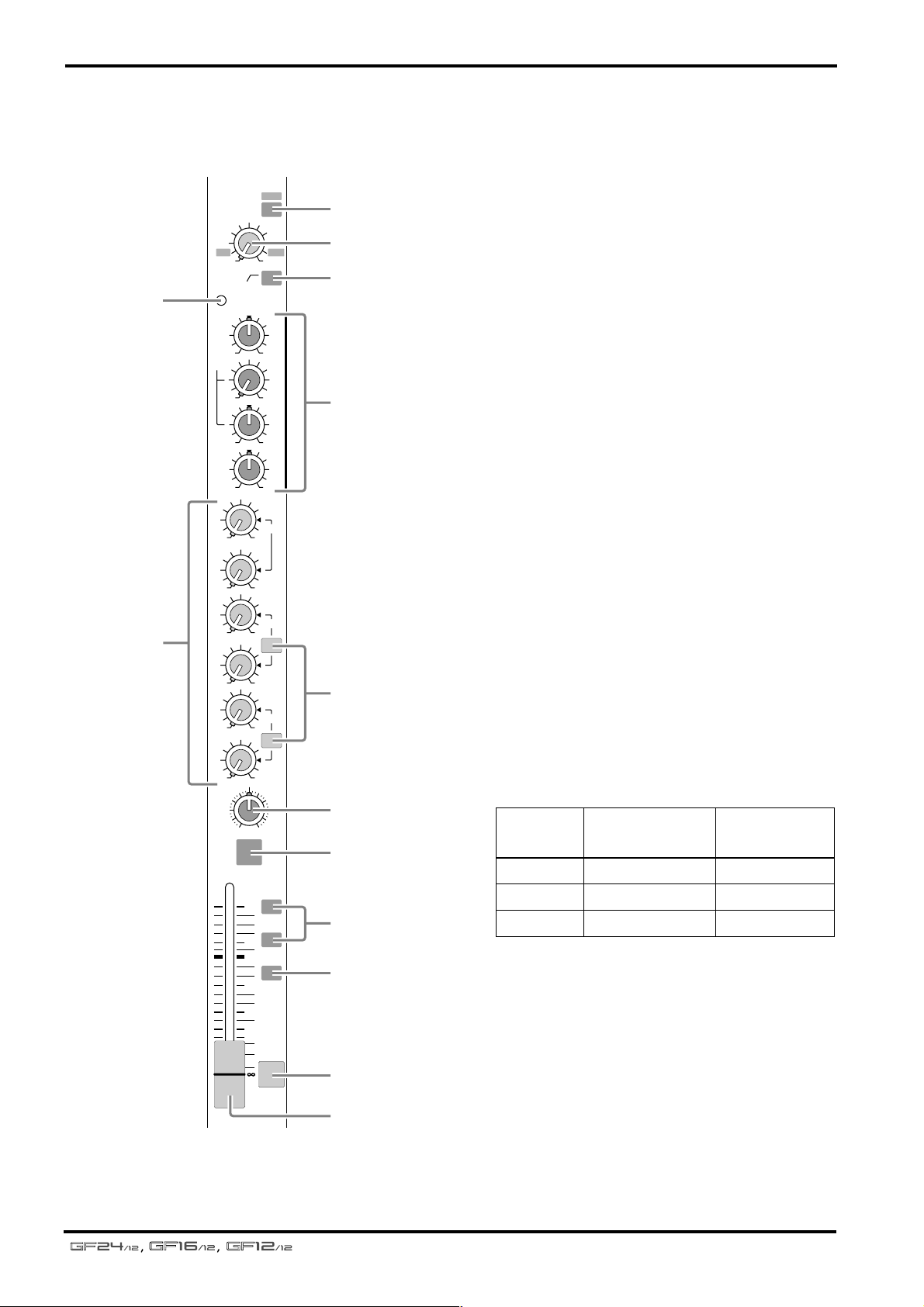
Channel controls
■
Mono input channels
4
6
GAIN
+10
–16
80
PEAK
HIGH
–15 +15
MID
250 5K
–15 +15
LOW
–15 +15
AUX
1
010
2
010
3
010
4
010
5
010
6
010
PAN
L
ODD
ON
10
5
0
5
10
15
20
30
40
26dB
–34
–60
PRE
PRE
PRE
R
EVEN
1–2
3–4
ST
PFL
1
2
3
5
7
8
9
0
A
B
C
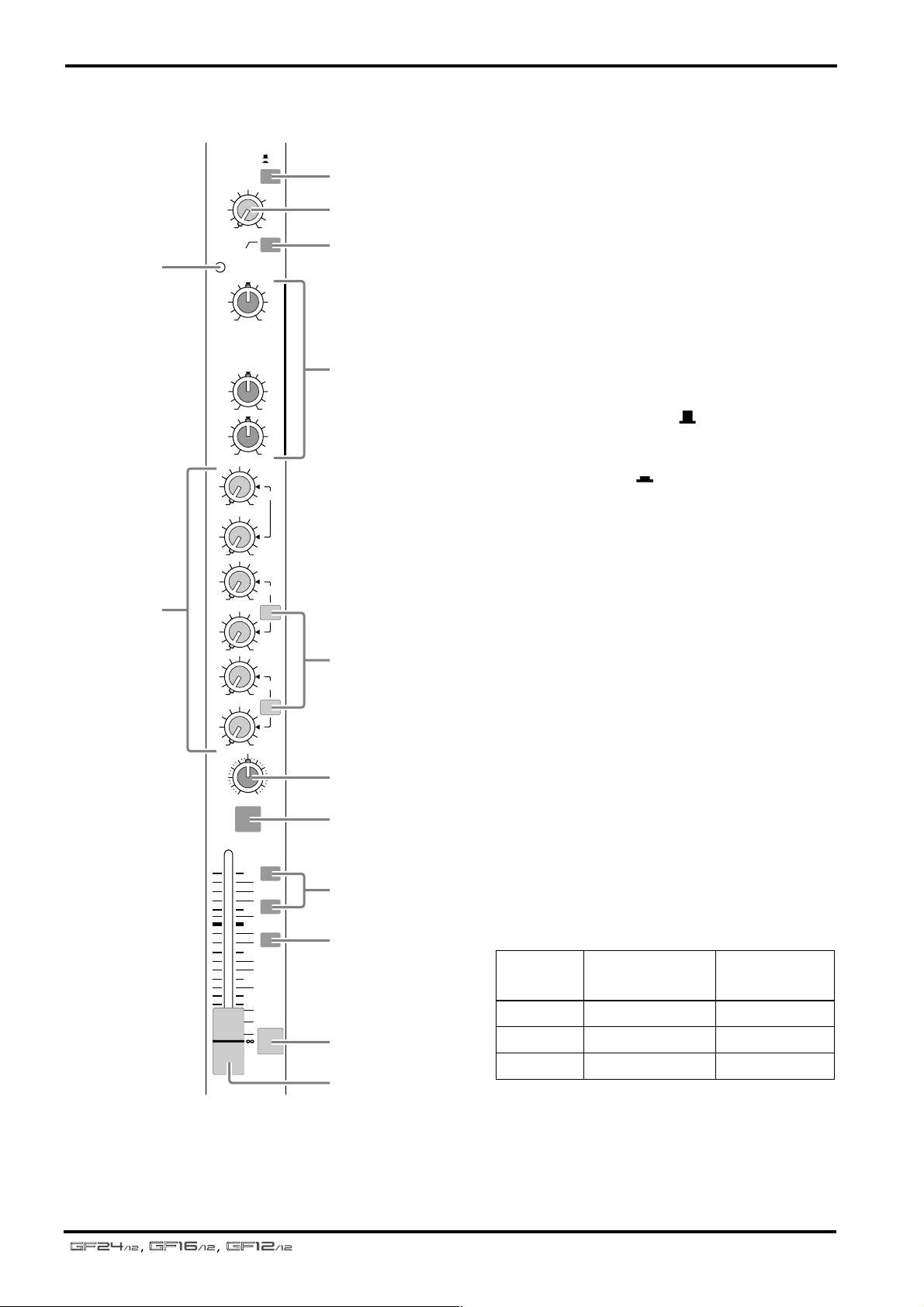
Here are the 20 {12, 8} mono input channels of
the GF24/12 {GF16/12, GF12/12}. The input
channel section processes the signal from the
input jacks of the connector section, and sends
the result to the GROUP buses, AUX buses, and
the ST bus.
1
Pad switch
This attenuates the input signal by 26 dB. The
pad is on when this switch is pressed in.
2
GAIN control
This adjusts the input sensitivity. The range of
levels that can be accommodated is –16 dB to
–60 dB when the pad switch ( 1 ) is off, and
+10 dB to –34 dB when the pad switch is on.
3
High pass filter switch
This is an on/off switch for the high pass filter
that cuts the frequency range below 80 Hz at a
slope of 12 dB/octave. The high pass filter is on
when the switch is pressed in.
4
PEAK indicator
This is an indicator that detects post-EQ clipping.
It will light 3 dB before clipping, indicating that
the signal is near the clipping level. If this LED
lights, lower the GAIN control ( 2 ).
5
EQ controls (HIGH/MID/LOW)
This is a three-band equalizer that boosts/cuts
each frequency band over a
±
15 dB range. The
center frequency and equalizer type for each
band is shown below.
Band
HIGH 10 kHz shelving
MID 250 Hz–5 kHz peaking
LOW 100 Hz shelving
Center
frequency
Type
The response is flat when the knob is in the “
position.
6
AUX controls (1–6)
These knobs adjust the level at which the input
channel signal is sent to the AUX buses 1–6. AUX
controls 1 and 2 are fixed at pre-fader, and AUX
controls 3–6 can be switched between pre/post
fader using the PRE switch ( 7 ). When a knob is
in the “ √ ” position, the level is “nominal”.
▼
”
—Owner’s Manual
PRE switches
7
These switches select whether the pre or post fader signal will be sent to AUX buses 3–6. This
setting is switched in pairs: AUX 3/4 and 5/6.
When the switch is pressed in, the pre-fader signal will be sent to the corresponding pair of AUX
buses. When the switch is in the out (up) position, the post-fader signal will be sent.
8
PAN control
This adjusts the left/right position at which the
input channel signal will be sent to the ST (stereo) bus, GROUP bus 1/2, and GROUP bus 3/4.
ON switch
9
This switches the input channel on/off. When
this switch is turned off, the signal of the input
channel will not be sent to the ST bus, GROUP
buses, or AUX buses. However even if this switch
is off, you can use the PFL switch ( B ) to monitor
the signal from the C-R OUT jacks or the
PHONES jack.
Channel controls
Group select switches
0
These switches send the signal of the input channel to GROUP buses 1–4. When the 1–2 switch is
on (pressed in) the signal will be sent to GROUP
bus 1/2. When the 3–4 switch is on, the signal will
be sent to GROUP bus 3/4.
A
ST (stereo) switch
This switch sends the signal of the input channel
to the ST bus. When this switch is on, the signal
will be sent to the ST bus.
B
PFL (pre-fader listen) switch
This switch sends the pre-fader signal to the PFL/
AFL bus, allowing you to monitor it through
headphones or monitor speakers. When this
switch is on, the pre-fader signal of the input
channel can be heard from the C-R OUT jacks
and the PHONES jack, even if the ON switch
( 9 ) is off.
C
Channel fader
This fader adjusts the input level of the input
channel. The position of the channel fader will
affect the level of the signal that is output from
the ST bus, GROUP buses 1–4, and AUX buses 1–
6 (except when the PRE switch is on for AUX
buses 3–6).
7
INPUT A
1-20
{1-12}
{1-8}
INPUT B
PHANTOM
PHANTOM
+48V
PAD
26dB
+48V
HA
GAIN
PEAK
g
HIGH
PFL
HPF
80
INSERT I/O
0dB
3 Stage EQ
g
LOW
f
g
MID
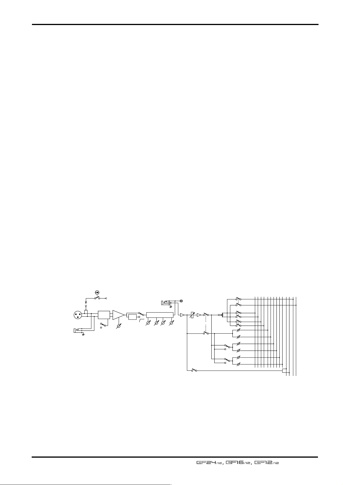
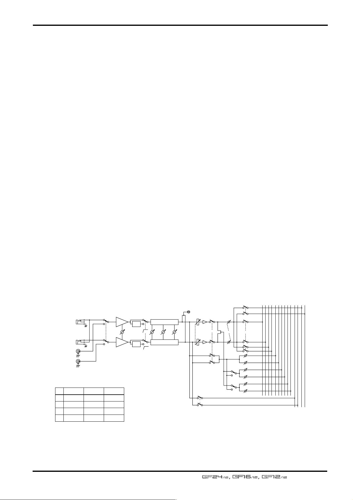
Mono input channel signal flow
AUX
GROUP
4321
ST
PAN
ON
PRE
PRE
1-2
3-4
AUX 1
AUX 2
AUX 3
AUX 4
AUX 5
AUX 6
PFL/AFL
654321
LR
ST
RL
—Owner’s Manual
Front and rear panel
8
■
Stereo input channels
4
6
GAIN
+10 –34
80
PEAK
HIGH
–15 +15
MID
–15 +15
LOW
–15 +15
AUX
1
010
2
010
3
010
4
010
5
010
6
010
BAL
L
EVEN
ODD
ON
10
5
0
5
10
15
20
30
40
PRE
PRE
PRE
1–2
3–4
ST
PFL
A
B
1
2
Here are the two stereo input channels provided
by the GF24/12, GF16/12, and GF12/12. The
INPUT 21/22 and 23/24 {13/14 and 15/16 on the
GF16, and 9/10 and 11/12 on the GF12/12} jacks
( 6 and 0 of the connector section) are pairs of
3
connectors that let you control a stereo signal
using one input channel. If a cable is connected
only to the INPUT A 21L or 23L jack {13L or 15L
on the GF16/12, or 9L or 11L on the GF12/12},
the source will be controlled as a monaural signal.
5
A/B switch
1
This switch selects input jacks. When the switch
is in the upward position ( ) the input signal of
the INPUT A jack is selected (page 18, 6 of the
connector section). When the switch is in the
downward section ( ), the input signal of the
INPUT B jack is selected ( 0 of the connector
section).
GAIN control
2
This adjusts the input sensitivity. The range of
levels that can be accommodated is +10 dB to
–34 dB.
3
High pass filter switch
7
This is an on/off switch for the high pass filter
that cuts the frequency range below 80 Hz at a
slope of 12 dB/octave. The high pass filter is on
when the switch is pressed in.
4
PEAK indicator
This is an indicator that detects post-EQ clipping.
R
8
It will light 3 dB before clipping, indicating that
the signal is near the clipping level. If this LED
9
lights, lower the GAIN control ( 2 ).
5
EQ controls (HIGH/MID/LOW)
This is a three-band equalizer that boosts/cuts
0
each frequency band over a
±
15 dB range. The
center frequency and equalizer type for each
A
B
C
band is shown below.
Band
HIGH 10 kHz shelving
MID 250 Hz peaking
LOW 100 Hz shelving
Center
frequency
Type
The response is flat when the knob is in the “
▼
”
position.
—Owner’s Manual
AUX controls (1–6)
6
These knobs adjust the level at which the input
channel signal is sent to the AUX buses 1–6. AUX
controls 1 and 2 are fixed at pre-fader, and AUX
controls 3–6 can be switched between pre/post
fader using the PRE switch ( 7 ). When a knob is
in the “ √ ” position, the level is “nominal.”
7
PRE switches
These switches select whether the pre or post fader signal will be sent to AUX buses 3–6. This
setting is switched in pairs: AUX 3/4 and 5/6.
When the switch is pressed in, the pre-fader signal will be sent to the corresponding pair of AUX
buses. When the switch is in the upward position,
the post-fader signal will be sent.
8
BAL (balance) control
This adjusts the left/right balance at which the
signal of the stereo input channel will be sent to
the ST (stereo) bus, GROUP bus 1/2, and
GROUP bus 3/4.
9
ON switch
This switches the input channel on/off. When
this switch is turned off, the signal of the input
channel will not be sent to the ST bus, GROUP
buses, or AUX buses. However even if this switch
is off, you can use the PFL switch ( B ) to monitor
the signal from the C-R OUT jacks or the
PHONES jack.
Channel controls
Group select switches
0
These switches send the signal of the input channel to GROUP buses 1–4. When the 1–2 switch is
on (pressed in) the signal will be sent to GROUP
bus 1/2. When the 3–4 switch is on, the signal will
be sent to GROUP bus 3/4.
A
ST (stereo) switch
This switch sends the signal of the input channel
to the ST bus. When this switch is on, the signal
will be sent to the ST bus.
B
PFL (pre-fader listen) switch
This switch sends the pre-fader signal to the PFL/
AFL bus, allowing you to monitor it through
headphones or monitor speakers. When this
switch is on, the pre-fader signal of the input
channel can be heard from the C-R OUT jacks
and the PHONES jack, even if the ON switch
( 9 ) is off.
C
Channel fader
This fader adjusts the input level of the stereo
input channel. The position of the channel fader
will affect the level of the signal that is output
from the ST bus, GROUP buses 1–4, and AUX
buses 1–6 (except when the PRE switch is on for
AUX buses 3–6).
9
INPUT A
INPUT B
No.
*1
*2
*3
*4
*1,*3
(MONO)
*2,*4
*1,*3
*2,*4
GF12/12
9L
10R
11L
12R
GF16/12
13L
14R
15L
16R
A
B
GF24/12
21L
22R
23L
24R
AUX
GROUP
4321
PEAK
HA
HPF
GAIN
HA
HPF
3 Stage EQ
PFL
ON
BAL
80
80
LOW
3 Stage EQ
MID
HIGH
PRE
PRE
ST
1-2
3-4
AUX 1
AUX 2
AUX 3
AUX 4
AUX 5
AUX 6
PFL/AFL
654321
LR
ST
RL
Stereo input channel signal flow
—Owner’s Manual
 Loading...