

Page 1

Y AMA HA
DIGITAL PROGRAMMABLE ALGORITHM SYNTHESIZER
OWNER’S MANUAL
Page 2
SUPPLEMENTAL MARKING INFO RMATION
Yamaha Digital Musical Instrument Products will have either a label similar to the graphic shown below or a molded/stamped
facsimile of the graphic on its enclosure. The explanation of these graphics appears on this page. Please observe all cautions
indicated.
The Exclamation point within an equilateral triangle is intended to alert the user
to the presence of important operating
and maintenance (servicing) instructions
in the literature accompanying the product.
The lightning flash with arrowhead sym-
CAUTION: TO REDUCE THE RISK OF
ELECTRIC SHOCK DO NOT REMOVE
COVER (OR BACK). NO USER-SERVICEABLE
PARTS INSIDE. REFER SERVICING TO
QUALIFIED SERVICE PERSONNEL
bol, within an equilateral triangle, is intended to alert the user to the presence
of uninsulated “dangerous voltage”
within the product’s enclosure that may
be of sufficient magnitude to constitute
a risk of electric shock to persons.
SPEC IA L MESSAG E SECTION
ELECTROMAGNETIC INTERFERENCE (RFI): Your Yamaha
Digital Musical Instrument Product has been type tested and
found to comply with all applicable regulations. However,
if it is installed in the immediate proximity of other electronic
devices, some form of interference may occur. For additional
RFI information see FCC information section located in this
manual.
IMPORTANT NOTICE: This product has been tested and
approved by independent safety testing laboratories in order
that you may be sure that when it is properly installed and
used in its normal and customary manner, all foreseeable
risks have been eliminated. DO NOT modify this unit or
commission others to do so unless specifically authorized
by Yamaha. Product performance and/or safety standards
may be diminished. Claims filed under the expressed war-
ranty may be denied if the unit is/has been modified. Implied
warranties may also be affected.
SPECIFICATIONS SUBJECT TO CHANGE: The information
contained in this manual is believed to be correct at the time
of printing. Yamaha reserves the right to change or modify
specifications at any time without notice or obligation to
update existing units.
NOTICE: Service charges incurred due to a lack of knowledge relating to how a function or effect works (when the
unit is operating as designed), are not covered by the
manufacturer’s warranty. Please study this manual carefully
before requesting service.
STATIC ELECTRICITY CAUTION: Some Yamaha Digital
Musical Instrument products have modules that plug into the
unit to perform various functions. The contents of a plug-in
module can be altered/damaged by static electricity dis-
charges. Static electricity build-ups are more likely to occur
during cold winter months (or in areas with very dry climates) when the natural humidity is low. To avoid possible
damage to the plug-in module, touch any metal object (a
metal desk lamp, a door knob, etc.) before handling the
module. If static electricity is a problem in your area, you
may want to have your carpet treated with a substance that
reduces static electricity build-up. See your local carpet
retailer for professional advice that relates to your specific
situation.
Model
Serial No.
Purchase Date
This information on safety is provided to comply with U.S.A. laws. but should be observed by users in all countries.
Page 3

Welcome
Welcome to the DX7s, the newest member of the growing family of FM digital
synthesizers from Yamaha. Using the industry-standard DX7 as its starting point, the
DX7s offers a number of important new features, such as improved sound quality,
additional FM features, new performance options, and improved controls.
Since there is so much material available on the DX7 family of synthesizers (and on the
theory of FM digital synthesis), this manual will not be an FM tutorial. Instead, it has
been designed to be a “users manual” in the truest sense — its goal is to help you make
music with your new DX7s as quickly as possible.
If you are already familiar with the operation of the original DX7, this manual will help
you make the transition to the DX7s in short order. On the other hand, if this is your first
FM digital instrument, this manual will guide you into the operation of your new
synthesizer with easy-to-follow, step-by-step instructions and explanations.
After you are comfortable with the operation of your new synthesizer, you may want to
explore the fascinating world of FM digital voicing. If so, consult the extensive list of
reference works on FM synthesis listed in the bibliography at the back of this manual.
Page 4

Tips
The DX7s has been designed for years of trouhle-free use. In order to ensure that it
remains a healthy member of your family
following tips in mind:
of
musical instruments, please keep the
Installation:
When setting up the DX7s in your home or studio, avoid exposure to direct sunlight or
other sources of heat. Environments with excessive dust, cold, dampness, or vibration can
also damage your instrument. Even though the DX7s is electronic, you should treat it with
the same kind of care you would lavish on any other musical instrument.
Also, since the DX7s is electronic, you should make sure not to set it too close to
equipment (such as a television set) that generates electromagnetic fields. Such proximity
could cause both malfunctions in the synthesizer’s digital circuitry and interference noise
in the other unit.
Handling:
The DX7s is sturdy, but it can do without rough handling. Don’t subject it to sudden jolts
(such as dropping it), as this can damage the internal circuitry. If you plan to travel with it,
be sure to use a road case. Also, make sure not to apply excessive force to any of the keys,
buttons, or other controls.
Cleaning:
To clean or dust your DX7s, use nothing more than a clean, slightly damp cloth. Using
chemical solvents will damage the finish, and using too much water may do considerable
damage to the internal circuitry.
AC Power & Other Equipment:
When you are using the DX7s with an amplifier or mixer that has unbalanced outputs,
connect both units to the same AC outlet to avoid hum.
If you use a number of electronic instruments in your setup, you may want to consult an
electrician, who can make sure that your system does not overtax the available power.
Page 5

AC Power & Down Time:
Whenever the DX7s will not be used for an extended period of time, it is best to protect it
from potential disaster. Electrical storms and other natural or man-made disasters can give
rise to power surges, which may damage the digital circuitry of your DX7s — even if the
power is turned off. Either unplug your instrument when not in use, or invest in power
strips with surge protectors to safeguard all of your electronic equipment.
Service & Your Warranty:
The DX7s contains no user-serviceable parts. Opening it up or tampering with it in any
way will void the warranty, and may also lead you to experience some nasty electrical
shocks. If you have a problem with your instrument, please take it to an authorized
Yamaha service center.
Modifications & Your Warranty:
Unless you are assured to the contrary in writing, you should assume that any
modifications made to your DX7s will void the original product warranty. Therefore, you
should make sure that you receive a warranty (or some other kind of guarantee) from the
person or company that is responsible for the modification.
Page 6

Contents
1
Section 1: Playing the DX7s
3
Getting Started
6
Setting the ROM Cartridge Banks
8
Exploring the DX7s Performance Library
12
Exploring the DX7s Voice Library
16
The Play Modes
17
Using Controllers with the DX7s
19
Section 2: Creating and Storing New Sounds
Creating New Sounds
21
26
Saving New Sounds
29
Section 3: Using the New Performance Features
Performance Edit Buttons
31
33 Basic Performance Parameters
36 Performance Controllers
Micro Tuning
38
41
Section 4: Using the New Voice Features
43
Voice Edit Buttons
52
Basic Voice Editing Functions
53
New Voice Parameters
55
Voice Controllers
57
Fractional Scaling
59
Section 5: Memory
61
Utility Buttons
Memory Layout
64
66 Memory Storage Types
68
Basic Utility Functions
69
Cartridge Memory Functions
71
Section 6: MIDI
73
MIDI Buttons
75
System Setup
77
MIDI System Exclusives
Immediate MIDI Program Change Out
78
79
Appendices
80
Appendix 1:
81
Appendix 2: Bibliography
82
MIDI Implementation Chart
83
Blank Data Chart
Functions
Functions
Supplemental
Information
Page 7

Playing the DX7s
-1-
Page 8

Contents
3
Getting Started
3
Making Audio Connections
4
Turning on the DX7s
Setting the Volume Slider
5
Setting the ROM Cartridge Banks
6
Inserting the ROM Cartridge
6
Selecting the ROM Banks
7
Exploring the DX7s Performance Library
8
Selecting the Internal Performance Memories
8
The Internal Performance Memories
9
Selecting the Cartridge Performance Memories
10
The Cartridge Performance Memories
11
Exploring the DX7s Voice Library
12
Selecting the Internal Voice Memories
12
The Internal Voice Memories
13
Selecting the Cartridge Voice Memories
14
The Cartridge Voice Memories
15
The Play Modes
16
Voice Mode and Performance Mode
16
Using the 1 ~ 32/33 ~ 64 Button
16
Using the Poly/Mono Button
16
Using the Key Shift Button
16
Using Controllers with the DX7s
17
Pitch Bend Wheel
17
Modulation Wheel
17
17
After Touch
17
Breath Controller
Foot Controllers 1 and 2
18
Footswitches 1 and 2
18
Continuous Sliders 1 and 2
18
-2-
Page 9
Getting
Started
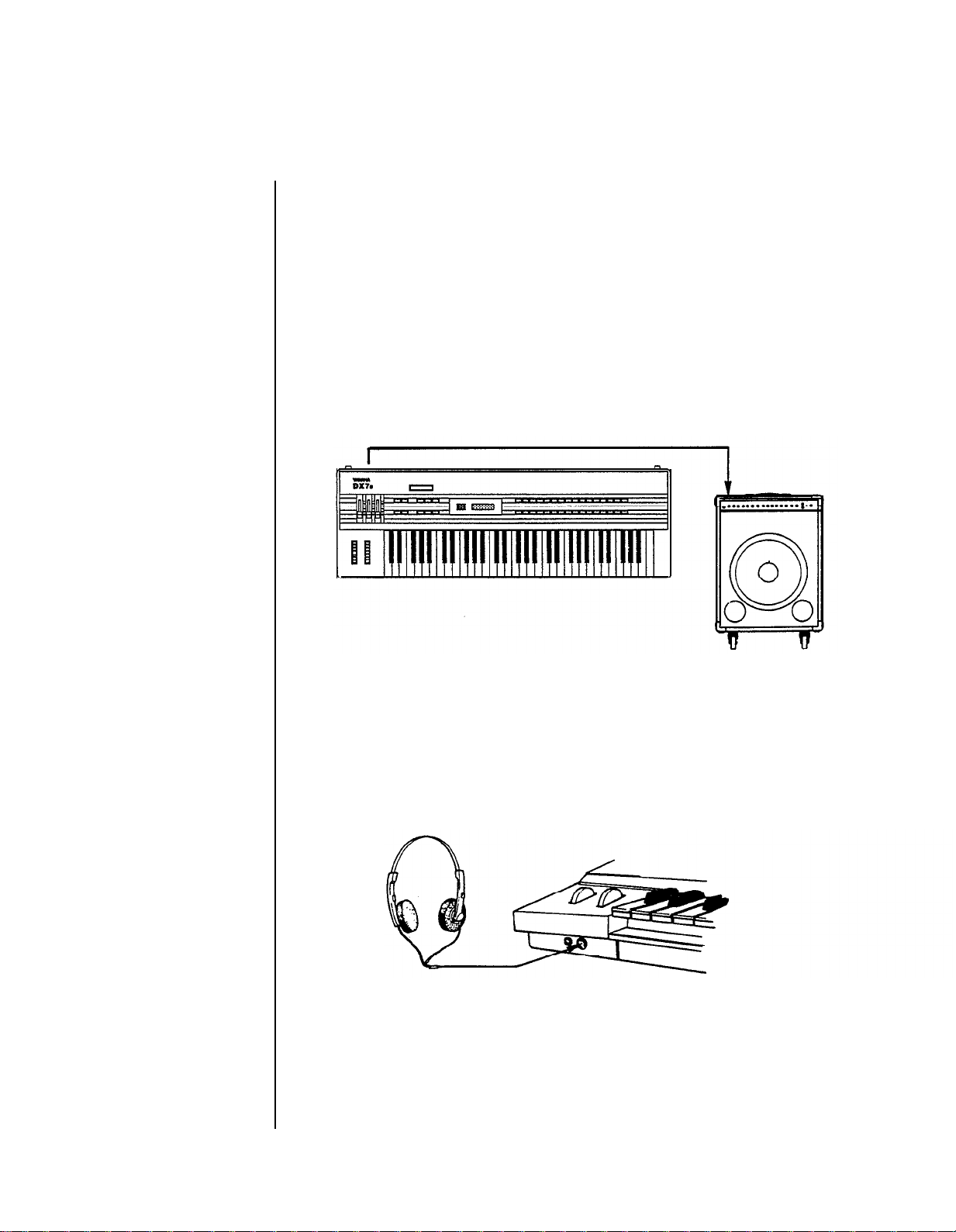
Connecting the DX7s
to a single input
amplifier.
You can begin to enjoy your DX 7s immediately, without poring through a lot of
complicated electronic theory. A ll you have to do is take the instrument out of the box and
proceed as follows:
Making Audio Connections
There are three different ways to connect the DX7s to sound reinforcement equipment.
The one you choose will depend on your situation:
you
1. If
have a monophonic (single input) amplifier such as a guitar amp, connect the
DX's output to the amp’s input (using a standard ¼” cable).
Using stereo headphones
with the DX 7s.
2. If you are using a multi-channel mixer, connect the DX’s back-panel audio output to
one of your mixer’s inputs (using a ¼” cable).
3. If you are using a set of standard stereo headphones, plug them into the DX’s Phones
output.
-3-
Page 10
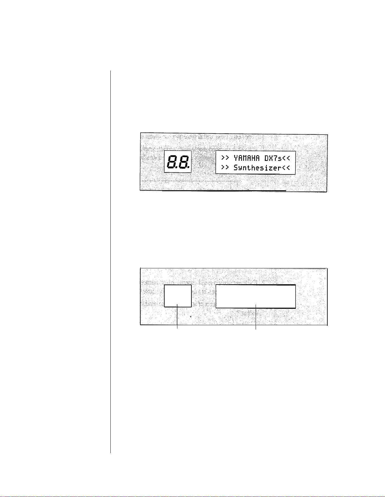
The DX’ s “ welcome” display.
Turning on the DX7s
After you have made the audio connection of your choice, turn the DX7s on by pressing
the power switch located on the right side of the back panel. This is the first display you
will see on the main panel:
After a few seconds, this display will be replaced by the last Play Mode display selected
before the DX7s was turned off:
The DX’ s next
initial display.
The LED’s will now display the voice or
performance number that was displayed
when the DX w as turned off.
The LCD will now show the voice or
performance name which corresponds to
the number in the LED.
-4-
Page 11
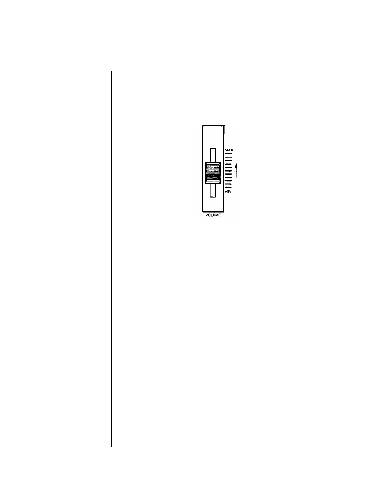
Volume Slider
Setting the Volume Slider
Since the volumes of the various voices differ, start with a setting in the middle of the
slider’s range; adjust later to suit your taste, depending on the voice or voices being
played.
-5-
Page 12
Setting the
ROM Cartridge
Banks
The ROM Cartridge supplied with your DX 7s actually contains several sets of data —
called “ banks.” These banks can be selected from the front panel. In order to hear all of
the Voice and Performance data, you will need to set the Voice/Performance bank to 2.
Also, certain voices in the DX7s are created using the new fractional scaling feature.
These scalings are stored in bank 3 of the ROM cartridge, so the Fractional Scaling Bank
will need to be set to bank 3. Look at the diagram on the next page and make the
necessary changes before you begin playing.
Inserting the ROM Cartridge
Before you begin to play your DX7s, insert the supplied ROM cartridge into the cartridge
slot:
-6-
Page 13
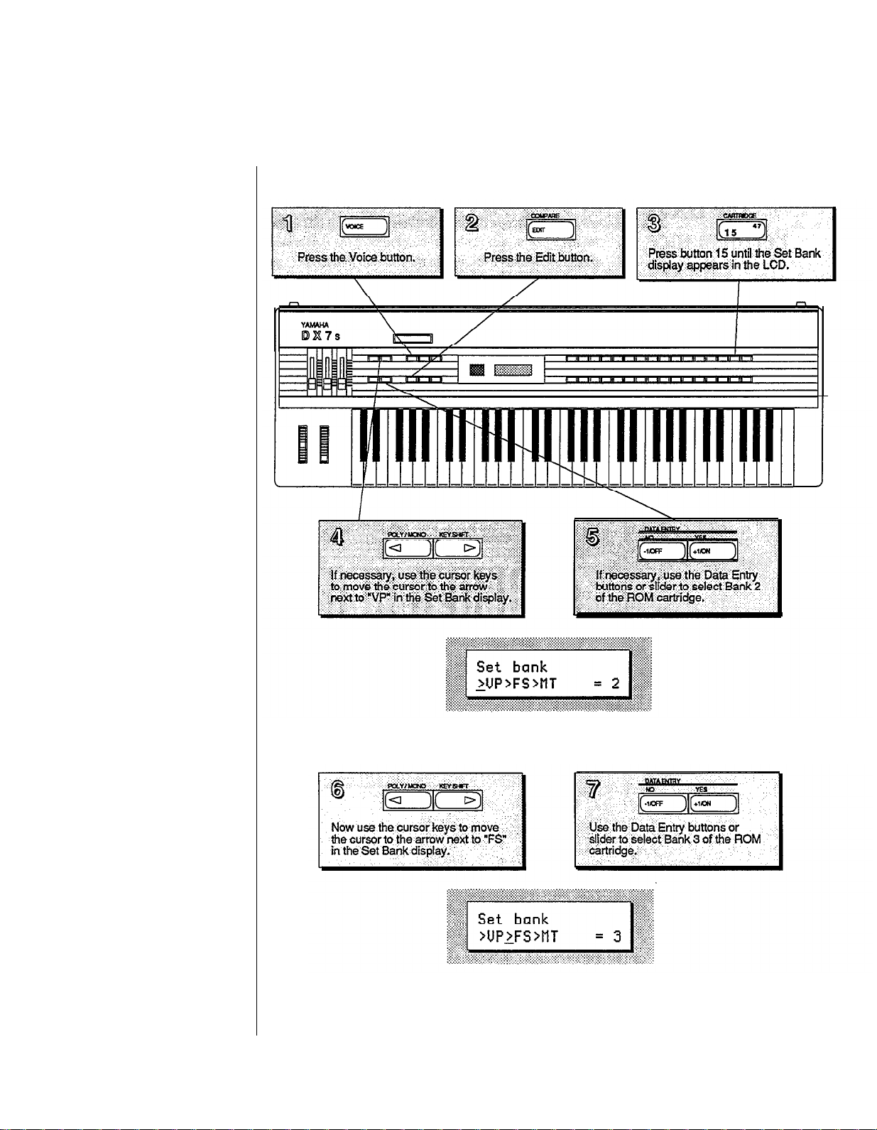
Selecting the ROM Banks
This is the Set Bank LCD display
with Bank 2 of the ROM cartridge
selected for Voice & Performance data.
This is the Set Bank LCD display
with Bank 3 of the ROM cartridge
selected for Fractional Scaling data.
-7-
Page 14
Exploring
the DX7s
Performance
Library
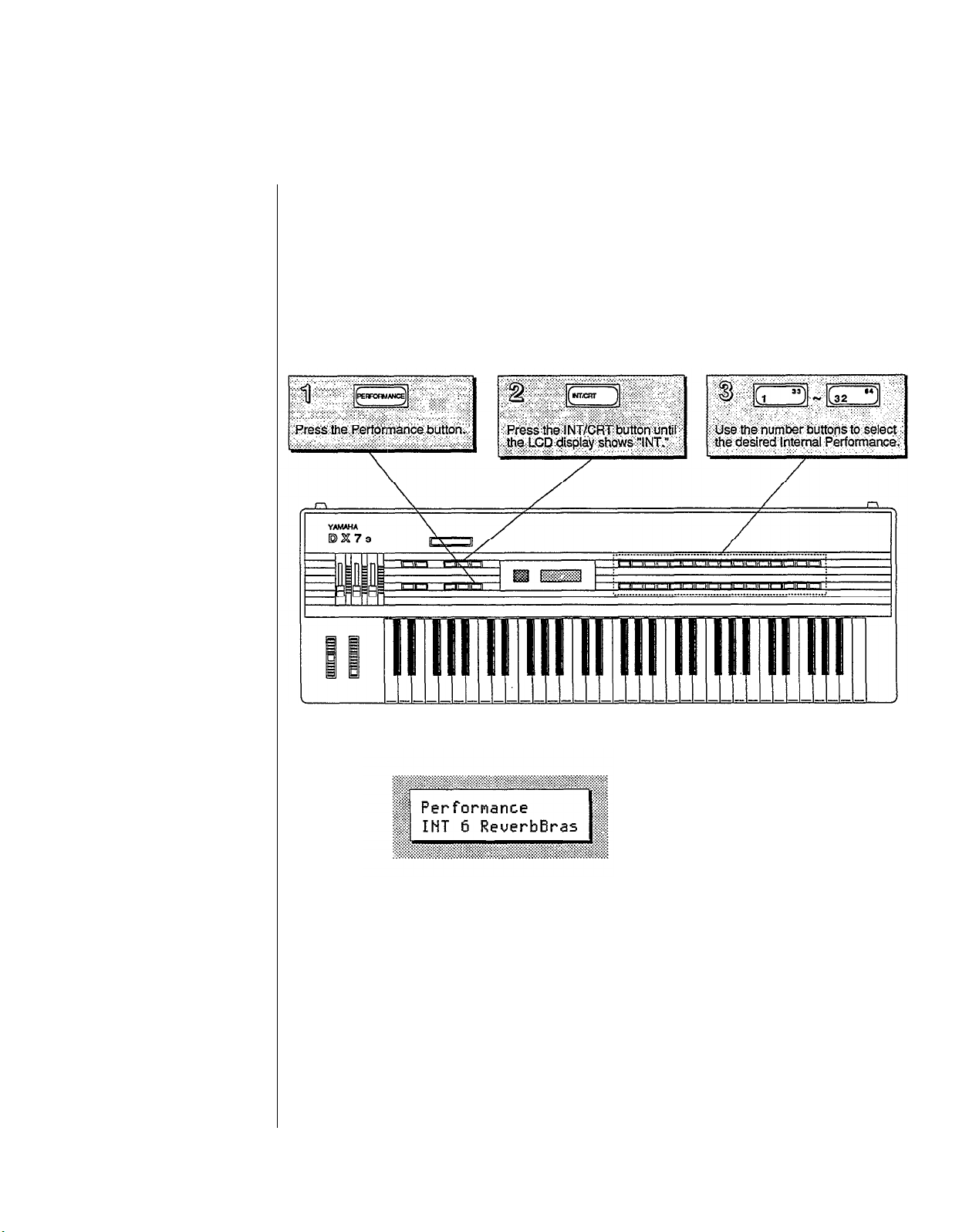
The Performance Mode is a completely new feature for the DX7s. It allows a number of
useful performance-oriented features to be stored and recalled instantly. These features
will be explained in detail in Sections 2 and
the steps below, and explore the richness of the Performance Mode by playing through all
of the new sounds available in the Internal and ROM Cartridge memories.
3
of this manual. For now, though, just follow
Selecting the Internal Performance Memories
-8-
The LCD display will show
the number and name of
the selected Performance
memory.
Page 15

The Internal Performance Memories
These are the
Performance Memories
loaded into the DX7s when it is
shipped from the factory.
Since these memories
can be adjusted,
your DX’s Internal Memory
may contain different data.
If so, reload the Internal Voice
& Performance
data from bank 4 of the
supplied ROM cartridge
(see page 70).
Performance
Name
1
SolidStrg
2
Strings
3
GrandOrch
4
Cello
5
LittleStrg
6
ReverbBras
7
BrightBras
8
MildBrass
9
W.Leed
10
SoftFlute
11
PanPipes
12
BlowSax
13
BluesHarp
14 Harp
15 PianoBrite
16 MildPiano
17 Mellow EP
18 Attack EP
19 Crystal EP
20 DX Clavi 1
21 DX Clavi 2
22 Clavicord
23 Harpsicord
24 WireString
25 GreatPipes
26 RotaryOrg
27 ConsoleOrg
28 MagicOrgan
29 SoftOrgan
30 SchoolOrg
31 AngelVoice
32 LadyVox
No.
Voice
12
INT
13
INT
15
INT
16
INT
19
INT
3
INT
8
INT
10
INT
20
INT
23
INT
26
INT
26
INT
29
INT
INT 30 Harp
INT 32 PianoBrite
INT 34 Piano 2
INT 36 RubbaRoad
INT 37 HardRoads
INT 38 FullTines
INT 39 ClaviStuff
INT 40 Clavi
INT 41 Clavecin
INT 45 HarpsiWire
INT 46 WireStrg A
INT 57 APuffOrgan2
INT 50 TapOrgan
INT 51 BriteOrgan
INT 52 MagicOrgan
INT 53 SoftOrgan
INT 58 Harmonium1
INT 60 Whisper A
INT 62 LadyVox
Voice
Name
HallOrch
NewOrchest
LiveStrg
BowedBass
Violins
ReverbBras
SilvaTrmpt
FrenchHorn
Bassoon
Flute
PanFloot
PanFloot
Harmonica
-9-
Page 16
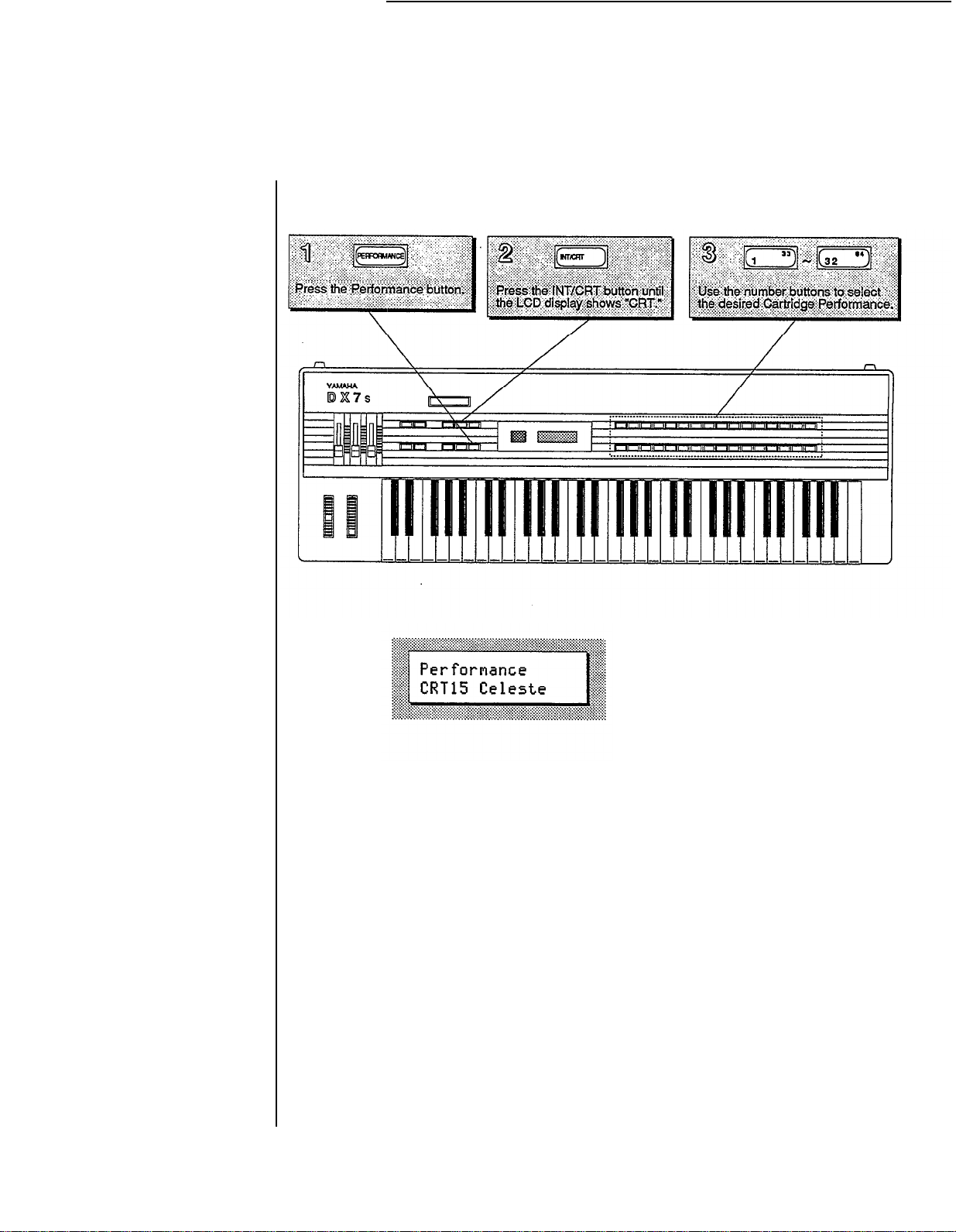
Selecting the Cartridge Performance Memories
The LCD display will show
the number and name of
the selected Performance
memory.
-10-
Page 17
The Cartridge Performance Memories
Bank 4 of the supplied
ROM cartridge contains the
Voice & Performance Memory
loaded into the DXs Internal
Memory when it is shipped
from the factory.
Bank 2 contains an entirely
different set of V oice &
Performance data.
Performance
Name
1 SuperBass
2 WoodBass
3 TackBass
4 FazzBass
5 PickGuitar
6 FolkGuitar
7 ClipGuitar
8 ChoGuitar
9 HitPad 1
10 HitPad 2
11 HitPad 3
12 AfroConga
13 Woodblock
14 Vibraphone
Voice
No.
CRT 1 SuperBass
CRT 2 StringBass
CRT 3 SkweekBass
CRT 6 OwlBass
CRT 9 GuitarBox
CRT 10 PickGuitar
CRT 13 YesBunk
CRT 14 12 Strings
CRT 17 Maribumba
CRT 19 Nu Marimba
CRT 20 StonePhone
CRT 25 CongaDrum
CRT 29 Claves
CRT 21 VibraPhone
Voice
Name
15 Celeste CRT 22 Celeste
16 GrandBells
17 MultiDrums
18 Tomtom
19 MalletBras
20 ClaviBrass
21 Ensemble
22 WarmBrass
23 Synclaria
24 PianoBells
25 St.Elmo's
26 OctiLate
27 EthnicBass
28 Wallop
29 Explosion
30 Thunderon
31 Laboratory
32 Motorcycle
CRT 30 Bells
CRT 23 Swissnare
CRT 24 Tom C4
CRT 37 MalletHorn
CRT 42 ClaviBrass
CRT 36 Ensemble
CRT 46 ElecBrass
CRT 40 ClariSolo
CRT 49 PianoBells
CRT 50 St.Elmo's
CRT 55 OctiLate
CRT 52 Pluk
CRT 60 Wallop
CRT 61 Explosion
CRT 63 Thunderon
CRT 64 Science
CRT 62 KoikeCycle
-11-
Page 18
Exploring
the DX7s
Voice
Library
The voices in the DX 7s were created using techniques like those used on the original
DX7. There are a number of new features available in Voice Mode (most
extensions of the Function Mode in the original DX 7). A ll of these features will he
discussed in detail in Sections 2 and 4 of this manual. For now, though, just follow the
steps below: and play through all of the voices available in the Internal and ROM
Cartridge memories.
of
them
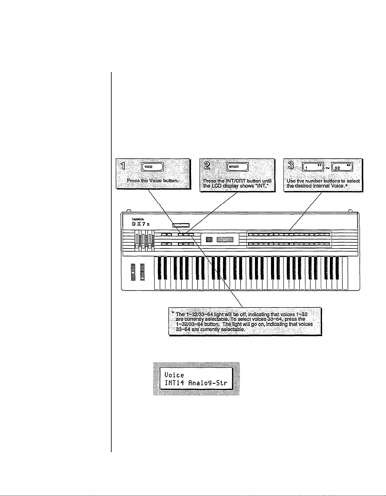
Selecting the Internal Voice Memories
The LCD display will show
the number and name of
the selected Voice memory.
-12-
Page 19
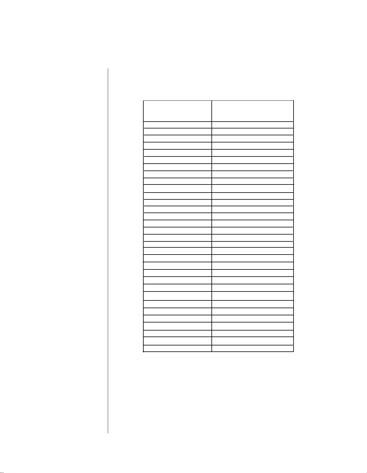
The Internal Voice Memories
These are the Voice Memories
loaded into the DX7s when it is
shipped from the factory.
Since these memories
can be adjusted,
your DX’s Internal Memory
may contain different data.
If so, reload the Internal Voice
& Performance
data from bank 1 of the
supplied ROM cartridge
(see page 70).
1 MellowHorn
2 SilvaBrass
33 Piano 1
34 Piano 2
3 ReverbBras35 KnockRoad
4 Tuba
5 Trombone
6 HardTrumps
7 Trumpet A
8 SilvaTrmpt
9 BC Trumpet
10 FrenchHorn
11 Strings
12 HallOrch
13 NewOrchest
14 Analog-Str
15 LiveStrg
16 BowedBass
17 EleCello A
18 EleCello B
19 Violins
20 Bassoon
21 Clarinet
22 Oboe
23 Flute
24 SongFlute
25 SpitFlute
26 PanFloot
27 Piccolo
28 Sax
29 Harmonica
30 Harp
31 EbonyIvory
32 PianoBrite
36 RubbaRoad
37 HardRoads
38 FullTines
39 ClaviStuff
40 Clavi
41 Clavecin
42 ClaviPluck
43 NasalClav
44 HarpsiBox
45 HarpsiWire
46 WireStrg A
47 WireStrg B
48 TouchOrgan
49 ShOrgan
50 TapOrgan
51 BriteOrgan
52 MajicOrgan
53 SoftOrgan
54 PipeOrgan
55 PuffOrgan1
56 PuffPipes
57 PuffOrgan2
58 Harmonium1
59 Harmonium2
60 Whisper A
61 Choir
62 LadyVox
63 MaleChoir
64 Whisper B
-13-
Page 20
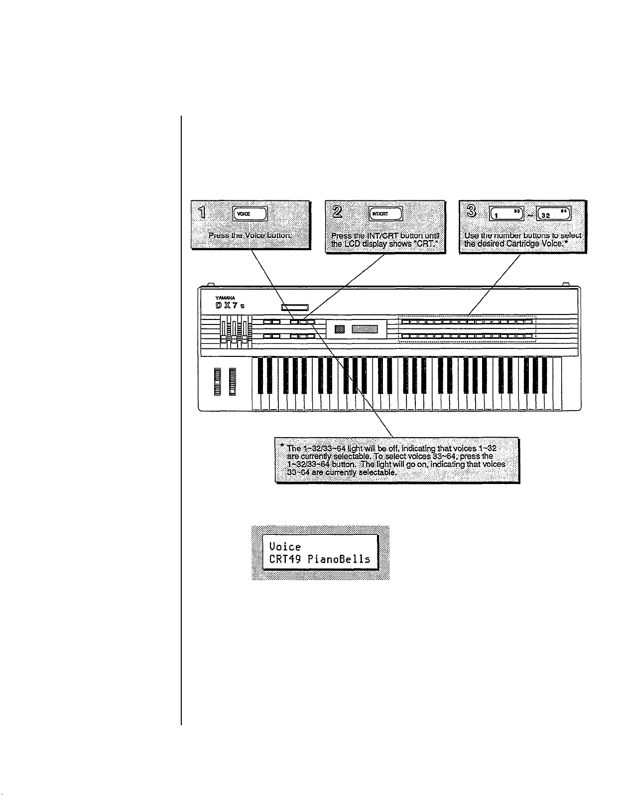
Selecting the Cartridge Voice Memories
As explained on page 6, the DX7s ROM cartridge contains several banks. To hear the
cartridge voices, make sure that the Voice/Performance bank is set to bank 2 of the ROM
cartridge (see page 7 for instructions on how to change the cartridge banks).
The LCD display will show
the number and name of
the selected Voice memory.
-14-
Page 21
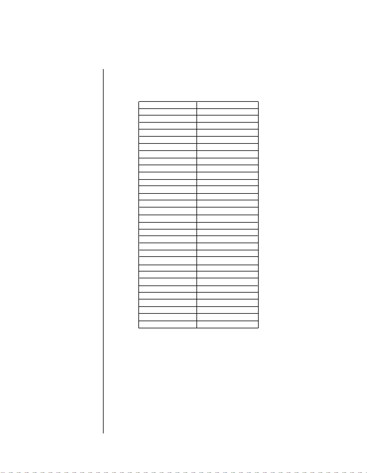
The Cartridge Voice Memories
Bank 4 of the supplied
ROM cartridge contains the
Voice & Performance Memory
loaded into the DX’s Internal
Memory when it is shipped
from the factory.
Bank 2 contains an entirely
different set of Voice &
Performance data.
1
SuperBass
2
StringBass
3
SkweekBass 35
SmoothBass
4
5BopBass
6
OwlBass
7JazzBass 39
8HardBass
9GuitarBox
10
PickGuitar 42ClaviBrass
11
FingaPicka
12
LeadaPicka
13
YesBunk
14
12 Strings
Classipika
15
16
Shami
Maribumba
17
18
DX Marimba
19
Nu Marimba
20
StonePhone 52 Pluk
21
VibraPhone
22
Celeste
Swissnare
23
24Tom C4 56
25
CongaDrum
26
Tub Bells
27
Gong
28
Timpani
29
Claves
Bells
30
StellCans
31
32
Handrum
33
Analog-X
34
Phasers
36
MalletHorn
37
38
FM-Growth
ElectoComb
40
ClariSolo
41
43WhapSynth
44
Whasers
45Fifths
46ElecBrass
ElectroBak
47
48
HarmoSynth
49
PianoBells
50
51
MilkyWays
TingVoice
53
Plukatan
54
OctiLate
55
LateDown
Glastine A
57
BellWahh
58
59
RubberGong
Wallop
60
Explosion
61
62
KoikeCycle
63
Thunderon
64
Science
FMilters
Ensemble
PitchaPad
St. Elmo's
- 15 -
Page 22
The Play Modes
Now that you have an idea of some
a closer look at how the various Play M odes operate. Read on:
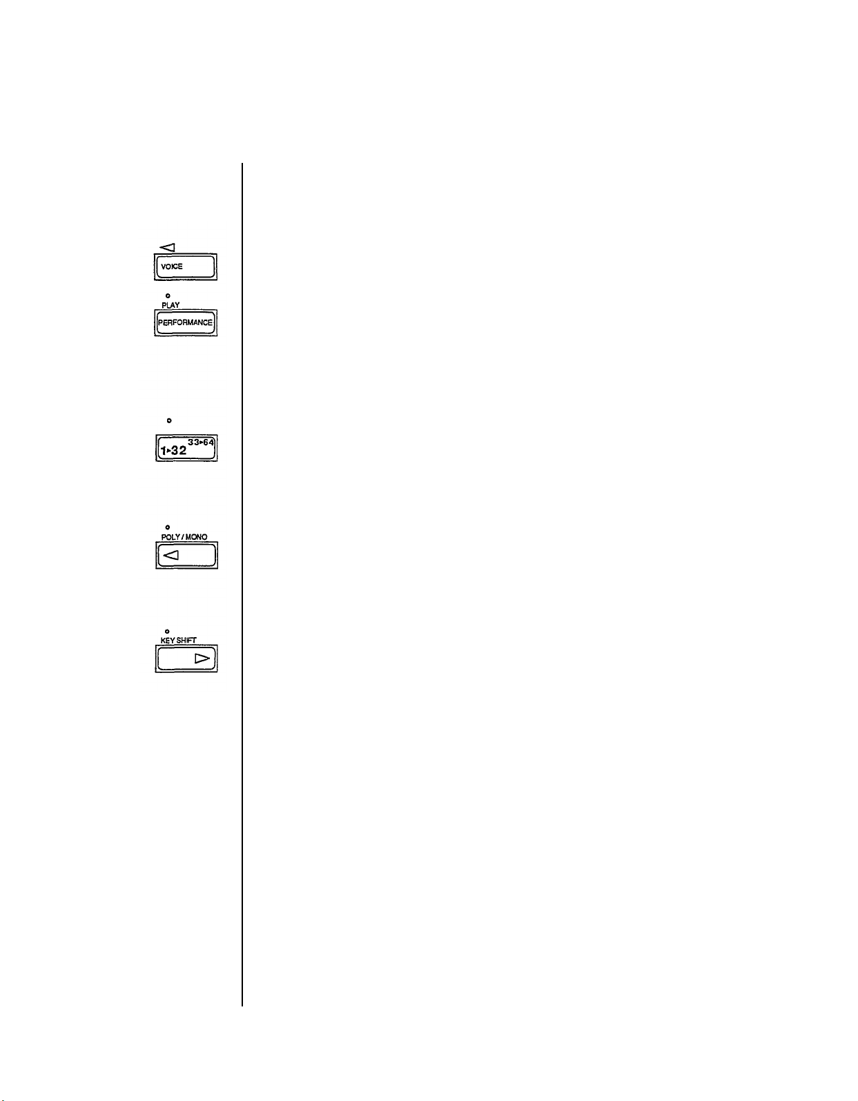
Voice Mode and Performance Mode
The DX7s has two different play modes: Voice Mode and Performance Mode. As you
have just seen, the Voice Mode is where you recall the 64 Internal Voice memories and
the 64 Cartridge Voice memories. Press Voice and use the 1 ~ 32/33 ~ 64 button and the
program number buttons to select specific voices. There are 32 Performance memories
that you can access by pressing Performance and the program number buttons. When you
are in Performance Mode, the light over the Performance button will be lit. When you
choose a Performance, features such as Micro Tune and Key Shift are added to the voice.
Using the 1 ~ 32/33 ~ 64 Button
The light above the 1 ~ 32/33 ~ 64 button tells you which set of voices can be selected. If
the light is off, voices 1 ~ 32 can be selected using the number buttons; if the light is lit,
voices 33 ~ 64 can be selected using the number buttons.
Using the Poly/Mono Button
The light above the Poly/Mono tells you which Key Mode is currently active in Play
Mode. If the light is off, the Key Mode is polyphonic; if the light is lit, the Key Mode is
monophonic. Key Modes will be explained further in Section 4.
of
the sound possibilities
of
the DX7s, it is time to take
Using the Key Shift Button
The Key Shift button determines whether the key shift programmed in Performance Mode
will be applied when you recall the Performance. If the light above Key Shift is off, no
key shift will be applied; if the light is lit, the preprogrammed key shift is applied.
- 16 -
Page 23
Using
Controllers
with the DX7s
The DX7s is designed to operate with many controllers, each of which can be set to
perform one of a number of different effects. The settings for these controllers can be
different for each Voice memory or Performance memory. To begin your exploration of
the expanded musical possibilities available with controllers on the DX7s, try the
examples listed below. Many of you may already be familiar with the operation of the
these controller’s; for those who are not, each section below begins with instructions on
how to locate or attach the controller in question.
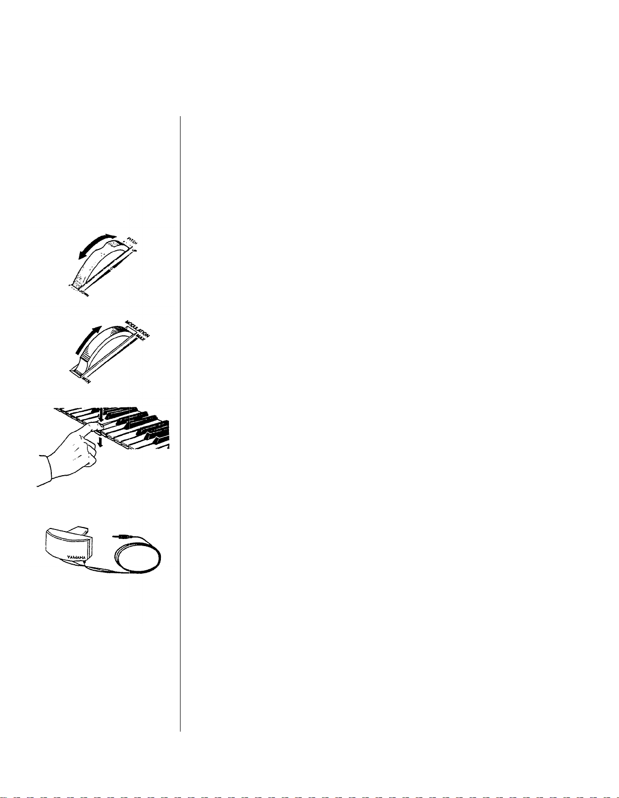
Pitch Bend Wheel
The Pitch Bend Wheel is located to the far left of the keyboard. To get an idea of some of
the effects possible with the Pitch Bend Wheel, use it with Internal Performance #1 or
Internal Performance #31. Move the Wheel both quickly and slowly as you play.
Modulation Wheel
The Modulation Wheel is located to the near left of the keyboard (to the right of the Pitch
Bend Wheel). For a taste of the possibilities of the Modulation Wheel, try it with Internal
Performance #6 or Internal Performance #13.
After Touch
After Touch is a keyboard feature that gives you extra control over a voice. It is engaged
by pushing down on the keys after they have already been depressed. To try some of the
effects available with After Touch, call up Cartridge Performance #4 or Cartridge
Performance #5 (from bank 2 of the ROM). After you have played a group of keys, press
them down into the key bed and listen to the result.
Breath Controller
The Breath Controller plugs into the mini-jack to the left of the Phones plug on the front
of the DX7s. It allows you a great deal of expressive control over the shape of the sounds
you play on the keyboard. Try using the Breath Controller in conjunction with Internal
Voice #9. With this voice, you will notice that playing on the keyboard by itself produces
no sound. In order to hear the voices, you must hold down keys and blow into the Breath
Controller.
- 17 -
Page 24
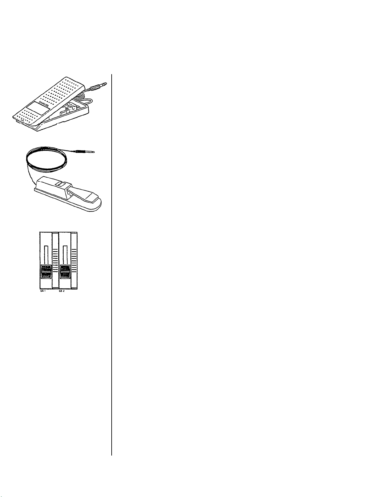
Foot Controllers 1 and 2
The Foot Controllers plug into the two Foot Controller plugs on the back panel of the
DX7s. They can give you continuous control over a number of aspects of the sounds. Try
using Foot Controller 1 with Cartridge Performance #25 or Internal Performance #12
(from bank 2 of the ROM). Foot Controller 2 is most often used as a volume pedal, but
other effects are possible.
Footswitches 1 and 2
The Footswitches plug into the two Footswitch plugs on the back panel of the DX7s.
Footswitch 1 acts much like a sustain pedal on a piano. Try it with Internal Performance
#19 or Cartridge Performance #5 to get an idea of the different effects that are possible.
Footswitch 2 can be used to engage a number of effects, including that of the soft pedal on
a piano. Try it in conjunction with Internal Performance #4 or Cartridge Performance #8
(from bank 2 of the ROM).
Continuous Sliders 1 and 2
The Continuous Sliders are located to the right of the Volume Slider on the left side of the
DX’s front panel. They can be programmed to give you control over many aspects of the
timbre of the sounds, and can even be used to alter parameters of a voice in real time. Try
using Continuous Slider 1 with Internal Performance #8 or Cartridge Performance #3.
Then listen to the effect that Continuous Slider 2 has on Internal Performance #3 or
Cartridge Performance #24.
- 18 -
Page 25

Creating and Storing
New Sounds
- 19 -
Page 26

Contents
Creating New Sounds
21
21
Editing and Edit Mode
Entering Edit Mode
22
Editing Performance and Voice Data
23
Using the Cursor Buttons and the Data Entry Buttons/Slider
23
23
Edit/Compare
Edit Button Quick Reference Guide
24
Saving New Sounds
26
Memory Protection
26
Turning Memory Protect Off
26
Voice and Performance Memory
26
Storing Performance Data to Internal or Cartridge Memory
27
Storing Voice Data to Internal or Cartridge Memory
27
- 20 -
Page 27
Creating
New Sounds
The Voices and Performance setups in the DX7s are stored as digital information in a
of
computer-like memory. And, like computer memory, the memory
for
altered
they do in electronic organs), but rather as streams
(edited) to create new Voice and Performance setups. To find out how this works, read on.
Editing and Edit Mode
Editing is the process of changing various settings of a Voice or Performance memory. In
the DX7s, this is accomplished in Edit Mode. Usually, you will use Edit Mode to create a
new Voice or Performance setup, but you can also use it to find out the parameter values
for the factory preset Voices and Performance setups.
Most of the buttons on the DX’s front panel have multiple functions. You can see this by
looking at the way the buttons are labeled on the front panel. For example, the +1 button
also functions as YES and ON. In most cases, the buttons will have different functions in
different operating modes.
The 32 number buttons are no exception: In the Play Modes, they are used to call up
various Voice and Performance memories; but, in the Edit Modes, they are used to access
the various parameter values that make up a sound.
Normally, when you enter the voice play mode (by pressing the voice button), the
performance parameters will automatically be initialized. If you then go into the
performance play mode (by pressing the performance button) the LCD display will show
you this by displaying “INIT PERF”.
different uses. In other words, voices do not exist as unchangeable presets (as
of
data. This data can be changed
the DX7s can be
Notice that the number in the LED changes to show which memory number you began
editing. When you switch between a voice parameter and a performance parameter, the
LED will show the corresponding number.
- 21 -
Page 28
In the Edit M ode, you can edit
both Voice and Performance
parameters.
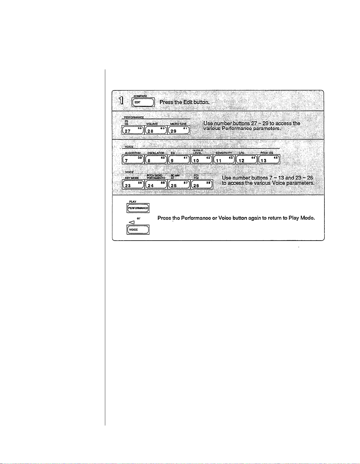
Entering Edit Mode
In the above procedure, the Edit Mode is entered after the Edit button is pressed in step
#1. At that time, you can push any or all of the buttons indicated as many times as
necessary to make the desired edits.
There is a distinction between editing Performance parameters and editing Voice
parameters that you may want to be aware of. In certain cases, (such as using compare)
you may not retain all your edits. It is a good idea to edit Performance and Voice data
separately (more on this later).
- 22 -
Page 29
Editing Performance and Voice Data
After entering one of the Edit Modes, use the number buttons to access the parameter
whose value you wish to change. Each number button calls up a variety of parameters,
often through the use of multiple LCD screen displays. A complete set of these screen
displays will be given at the beginning of Section 3 (for Performance parameters) and
Section 4 (for Voice parameters). In most cases, each LCD display gives you access to a
number of parameters.
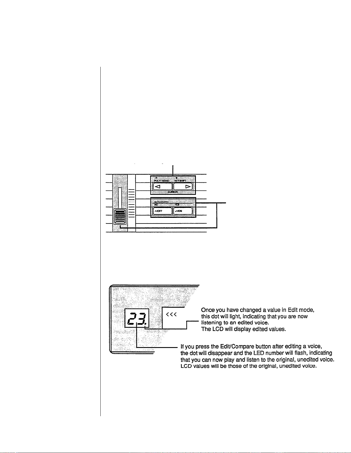
Using the Cursor Buttons and the Data Entry Buttons/Slider
The cursor buttons
and the data entry
slider/buttons.
The Edit/Compare
LED display.
In some cases, you will need to use these buttons to position the
next to the parameter you wish to edit.
Once you have selected the parameter
to edit (using the cursor buttons),
use the data entry slider or the
+1/-1 buttons to change the value of the
selected parameter.
The new values will appear in the
bottom row of the LCD,
and you will hear the effect
of these new values when you
play the keyboard.
LCD
cursor
Edit/Compare
Once you have started to edit a voice, you can compare your new sound to the original by
pressing the Edit/Compare button:
You may use the compare feature for Voice data, Performance data, or Micro Tune data. It
is best not to use compare when you are simultaneously editing more than one type of
data. For example, if you are editing Voice data, and then start editing Performance data,
using compare may cause Voice data to revert to the original.
- 23 -
Page 30
Voice parameters
are discussed in
more detail
in Section 4.
Voice parameters
are discussed in
more detail
in Section 4.
Edit Button Quick Reference Guide
-
24
-
Page 31

Performance parameters
are discussed in
more detail
in Section 3.
Utility parameters
are discussed in
more detail
in Section 5.
MIDI parameters
are
discussed in
more detail
in Section 6.
-25 -
Page 32

Saving
New Sounds
Once you have altered a particular Voice or Performance memory to your liking, you will
want to save your new data in one of the DX’ s memory locations. Voice memories and
Performance setups can be saved either to the Internal Memory or to a RAM Cartridge
Memory. To do so, proceed as follows:
Memory Protection
Each time the DX7s is turned on, it automatically powers up with both the Internal and
the Cartridge Memory Protect feature turned on. Before you can save data, you must turn
off this automatic memory protection.
Turning Memory Protect Off
Voice and Performance Memory
If you have edited both Performance data and Voice data, be sure to save the Voice data to
a Voice memory and a Performance data to a Performance memory. Both will need to be
saved independently.
-
26
-
Page 33

Storing Performance Data to Internal or Cartridge Memory
Storing Voice Data to Internal or Cartridge Memory
- 27
-
Page 34

-
28
-
Page 35

Using the New
Performance Features
-
29
-
Page 36

Contents
Performance Edit Buttons
31
Button 27 LCD Displays
31
Button 28 LCD Displays
31
Button 29 LCD Displays
32
Basic Performance Parameters
33
Total Volume
33
Key Shift
33
EG Forced Damp
34
Performance Name
35
Voice Number
35
Performance Controllers
36
Sustain Footswitch (FS 1)
36
Footswitch 2 (FS 2)
36
Continuous Sliders
37
FM Parameters Assignable to CS1 and
37
Micro Tuning
38
Selecting a Micro Tuning
38
The Micro Tuning Presets
38
Micro Tuning Editing and Storage
38
CS2
- 30 -
Page 37

Performance
Edit Buttons
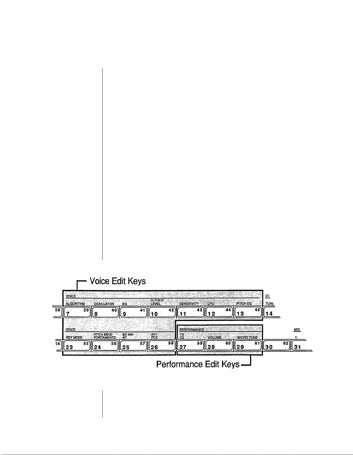
All of the Performance Mode parameters are adjusted via the LCD displays called up
using buttons 27 ~ 29. A ll of the these buttons call up multiple LCD displays. The charts
below show all of the displays called up by each button, and provide a complete list of
parameters and value ranges. In some cases, the first LCD display in a chart may not be
the first one you see. You may need to cycle through the displays (by pressing the button
repeatedly) until you reach the desired LCD display.
Buttons 27 LCD Displays
Button 28 LCD Displays
- 31 -
Page 38

Button 29 LCD Displays
-
32 -
Page 39

Basic
Performance
Accessed using buttons 28 and 29, these parameters determine the basic voice
relationships in Peformance Mode.
Parameters
Total Volume
This parameter allows you to set an overall volume for each Performance memory. If you
desire, you can use this setting to balance the levels of your Performance memories, so
that constant Volume Slider or mixer adjustments are not necessary.
Key Shift
This parameter allows you to adjust the transposition of the Performance. The
Performance can be adjusted up or down as much as two octaves (in halfsteps). The
original transposition of the voice is retained as part of the Voice memory, and the Key
Shift value is added to or subtracted from that Voice setting when you are in Performance
Mode. The light over the Key Shift button must be lit in order to hear changes made to
this parameter.
-33 -
Page 40

Under normal conditions,
the DX’s envelope
acts this way.
EG Forced Damp
Even though the DX7s is a 16-voice synthesizer, these voices can be used up quickly
when you use a Sustain Footswitch pedal. When you do exceed the DX’s note capacity,
the first notes played will stop sounding to make way for the new notes being played.
Under normal operating conditions, the DX7s considers these new notes to be
continuations of the first notes; therefore, the initial portions of the attack envelope will
not be retriggered:
If you wish to avoid this effect, turn the Forced Damping function on. It will force the
envelope to retrigger for each new note played:
Using the EG Forced Damping
parameter, the envelope is
forced to retrigger itself for
each new note played.
- 34 -
Page 41

Since you have a total of
ten characters to define
your Peformance Memory,
make sure that your
Performance Name conveys
the basic approach of the
specific Performance Memory.
Performance Name
You can enter a Performance Name of up to ten characters. To do so, follow the
instructions below.
Using the left and right cursor buttons while holding the
Edit/Character button lets you place the cursor over a
specific character position. This allows you to easily
edit any character within a name.
Using the Data Entry buttons while NOT holding the
Edit/Character button lets you switch between Large
or small characters. The +1 button selects the Large
character mode, the -1 button selects the small character
mode.
In addition to letting you enter small alpha characters, the small character input
mode lets you enter the following symbols as well.
Large mode
small mode
1 2 3 4 5 6
@
!
#
$ % ^ & * ( ) + ,
7
8
9
0
.
-
Voice Number
Each time you select a Performance, one of the 64 Internal or 64 Cartridge Voices is also
selected. You determine which voice will be selected via this display.
-35 -
Page 42

Performance
Controllers
The DX7s features a greatly expanded set of controller options. The settings for
Footswitches 1 and 2 and Continuous Sliders 1 and 2 are adjusted in Performance Edit
Mode, using button 27. (The other controller settings are accessed in voice parameters.)
Sustain Footswitch (FS 1)
Footswitch 1 is set to operate as a sustain pedal.
Footswitch 2 (FS 2)
Footswitch 2 is a multipurpose pedal with four selectable functions: Sustain, Portamento,
Key Hold, or Soft.
If Sustain is selected, FS 2 operates as a sustain pedal (just like FS 1).
If Portamento is selected, voice portamento effects will operate only when the pedal is
depressed.
If Key Hold is selected, only notes that are being held when the pedal is engaged will
sustain. This effect is similar to a piano’s sostenuto pedal.
If Soft is engaged, the pedal will soften the timbre and volume of the sound. You can edit
the range of the soft pedal by pressing button 27 again. The range is 1 ~ 7.
- 36 -
Page 43

Continuous Sliders
The two Continuous Sliders give you access to real-time control of FM voice parameters.
There are a total of 103 different possibilities:
FM Parameters Assignable to CS 1 and CS2
DATA ENTRY slider
The Continuous Sliders provide
a new avenue for exploration
of real-time timbral control.
highest position
l
l
l
l
l
l
l
l
l
l
Total level
OP 6
OP 1
AMP. MOD. SENS
OP 6
OP 1
Key velocity
OP 6
OP 1
EG Level 4 (L4)
OP 6
OP 1
EG Level 3 (L3)
OP 6
OP 1
EG Level 2 (L2)
O P 6
OP 1
EG Level 1 (L1)
OP 6
OP 1
EG Rate 4 (R4)
OP 6
OP 1
EG Rate 3 (R3)
OP 6
OP 1
EG Rate 2 (R2)
OP 6
OP 1
lowest
position
l
OP 6
EG Rate 1 (R1)
OP 1
l
OP 6
OSC. detune
OP 1
l
OP 6
Frequency fine
OPl
l
OP 6
Frequency coarse
OP 1
l
Portamento time
l
Pitch EG Level 4
l
l
l
l
l
l
No effect
Level 1
Pitch EG Rate 4
Rate 1
LFO AMD
PMD
PMS
Delay
Speed
Wave
Feedback level
Algorithm
Total volume
- 37 -
Page 44

Micro Tuning
The new DX7s contains eleven
preset Intonations, which
provides you with a good
introduction to alternate
intonation schemes.
Micro Tuning is another new feature for the DX 7s. It offers the possibility of performing
music using tuning and intonation systems other than Equal Temperament (which is the
current standard tuning for both pianos and synthesizers). Micro Tuning data is accessed
using button 29. New M icro Tunings are created in Micro Tuning Edit M ode, which is
accessed using button 14 in conjunction with button 29.
Selecting a Micro Tuning
The DX7s is equipped with eleven preset Micro Tunings as part of its permanent memory.
The Micro Tuning Presets
1
2
3
4
5
6
7
8
9
10
11
Equal
Pure (major)
Pure (minor)
Mean tone
Pythagorean
Werckmeister
Kirnberger
Vallotti, yong
1/4 Shift eql
1/4 Tone
1/8 Tone 1/8 Tone
Equal Temperament
Pure (Major)
Pure (Minor)
Mean tone
Pythagorean
Werckmeister
Kirnberger
Vallotti & Young
1/4 Shifted equal
1/4 Tone
In presets 2 ~ 5, the tuning can be adjusted according to the key of the music being
played.
Micro Tuning Editing and Storage
If you are interested in alternate tunings and intonations, you may want to create your
own sets of Micro Tuning data. The DX7s provides two memory locations for this
purpose: User 1 and User 2. These two sets of data are stored as part of the Internal
Memory, and will be stored along with all other Internal data when the Internal Voice &
Performance Memory is saved to another storage medium (such as a RAM cartridge). In
addition, up to 63 Micro Tunings can be saved to a RAM cartridge that has been properly
formatted for that purpose.
- 38 -
Page 45

Entering the
Micro Tuning
Edit Mode
Editing
Micro Tuning
Data
Storing
Micro Tuning
Data
- 39 -
Page 46

- 40 -
Page 47

Using the New
Voice Features
- 41 -
Page 48

Contents
Voice Edit Buttons
43
Button 7 LCD Display
43
Button 8 LCD Display
44
Button 9 LCD Display
44
Button 10 LCD Displays
45
Button 11 LCD Display
46
Button 12 LCD Display
47
Button 13 LCD Display
48
Button 23 LCD Displays
48
Button 24 LCD Displays
49
Button 25 LCD Displays
50
Button 26 LCD Displays
51
Basic Voice Editing Functions
52
Operator Select
52
52
Operator On/Off
52
EG Copy
New Voice Parameters
53
Pitch Envelope
53
53
LFO
54
Key Modes
Voice Controllers
55
Function Data and Voice Effect Data
55
Pitch Bend Modes
55
Foot Controller 1 and
55
Pitch Bias
56
Fractional Scaling
57
Fractional Scaling and Level Scaling
57
Fractional Scaling Editing and Storage
57
2
-42-
Page 49

Voice
Edit Buttons
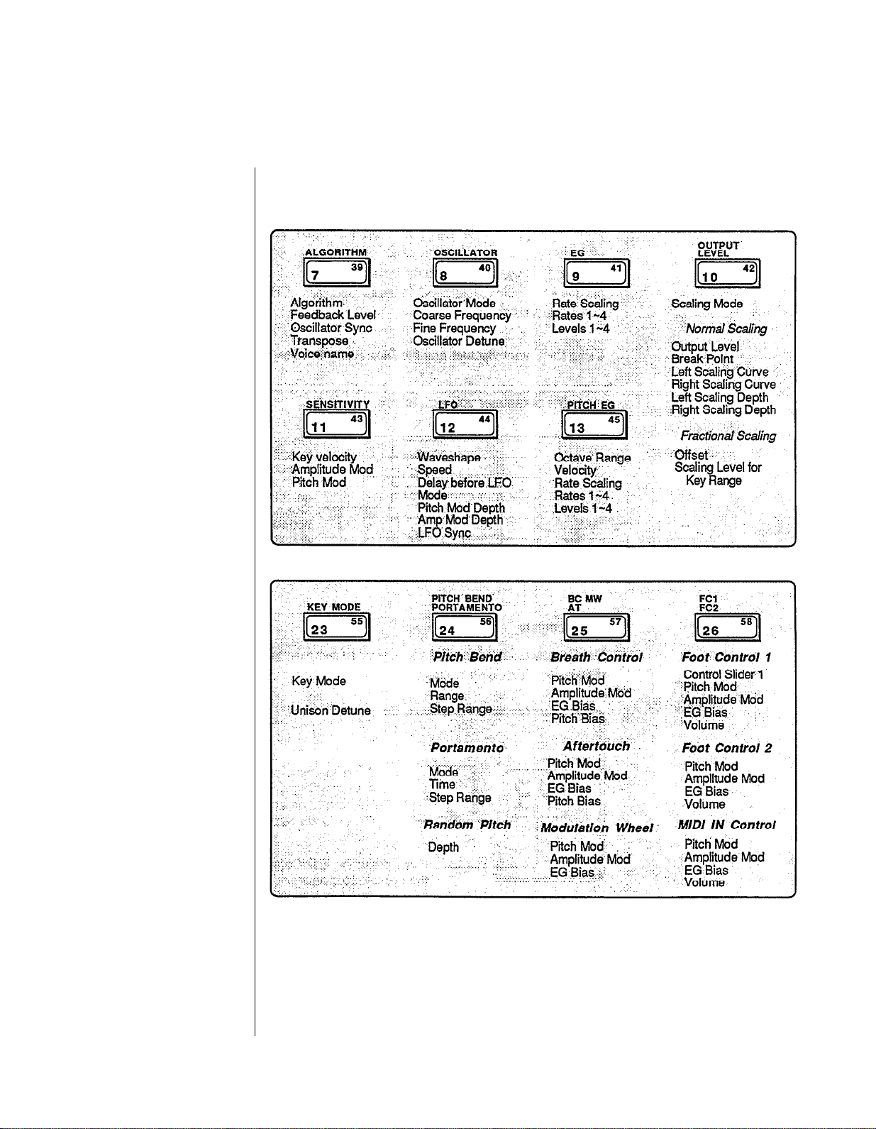
All of the Voice Mode parameters are adjusted via the LCD displays called up using
buttons 7 - 13 and 23 - 26. Many of the these buttons call up multiple LCD displays. The
charts below show all of the displays called up by each button, and provide a complete
list of parameters and value ranges. In some cases, the first LCD display in a chart may
not he the first one you see. You may need to cycle through the displays (by pressing the
button repeatedly) until you reach the desired LCD display.
Button 7 LCD Display
Algorithm
(1 ~ 32)
Feedback Level
(0 ~ 7)
Oscillator Key Sync
(off, on)
- 43 -
Transpose
(mid c = c1 ~ c5)
(The 'L' indicates Large or upper case
character entry mode)
Voice Name
(10 characters)
(The 's' indicates small or lower case
character entry mode)
Page 50

Button 8 LCD Display
Oscillator Mode
(ratio, fixed)
Frequency Coarse
(varies
Frequency Fine
(varies)
Oscillator Detune
(-7 ~ +7)
Button 9 LCD Display
- 44 -
Rate Scaling
(0 ~ 7)
Envelope Generator Rates 1 ~ 4
(0 ~ 99)
Envelope Generator Levels 1 ~ 4
(0 ~ 99)
Page 51

Button 10 LCD Displays
- 45 -
Page 52

Button 11 LCD Display
Key Velocity
(0 ~ 7)
Amplitude Modulation Sensitivity
(0 ~ 7)
Pitch Modulation Sensitivity
(0 ~ 7)
- 46 -
Page 53

Button 12 LCD Display
LFO Wave
(triangle, saw down, saw up,
square, sine, s/hold)
LFO Speed
(0 ~ 99)
LFO Delay
(0 ~ 99)
LFO Mode
(single, multi)
- 47 -
LFO Pitch Modulation Depth
(0 ~ 99)
LFO Amplitude Modulation Depth
(0 ~ 99)
LFO Key Sync
(off, on)
Page 54

Button 13 LCD Display
Pitch Envelope Octave Range
(1/2, 1,2,8)
Pitch Envelope Velocity
(off, on)
Pitch Envelope Rate Scaling
(0 ~ 7)
Pitch Envelope Rates 1 ~ 4
(0 ~ 99)
Button 23 LCD Displays
Pitch Envelope Levels 1 ~ 4
(0 ~ 99)
Key Mode Assign
(polyphonic, monophonic,
unison poly, unison mono)
Unison Detune
(0 ~ 7)
(appears only when Key Mode
= unison poly or unison mono)
-48-
Page 55

Button 24 LCD Displays
Pitch Bend Mode
(normal, lowest, highest, key on)
Pitch Bend Range
(0 ~ 12)
Pitch Bend Step
(0 ~ 12)
Portamento Mode
(Poly: sus-key, p retain, sus-key p follow)
(Mono: fingered porta, full time porta)
-49-
Portamento Time
(0 ~99)
Portamento Step
(0 ~ 99)
Random pitch
(0 ~ 7)
Page 56

Button 25 LCD Displays
Aftertouch
EG Bias
(0 ~ 99)
Aftertouch
Pitch Bias
(-50 ~ +50)
Modulation Wheel
Pitch Modulation Depth
(0 ~ 99)
Modulation Wheel
Amplitude Modulation Depth
(0 ~ 99)
- 50 -
Modulation Wheel
EG Bias
(0 ~ 99)
Page 57

Button 26 LCD Displays
Foot Controller 2
EG Bias
(0 ~ 99)
Foot Controller 2
Volume
(0 ~ 99)
MIDI Controller
Pitch Modulation
Depth
(0 ~ 99)
MIDI Controller
Amplitude Modulation
Depth
(0 ~ 99)
- 51 -
MIDI Controller EG Bias
(0 ~ 99)
MIDI Controller Volume
(0 ~ 99)
Page 58

Basic
Operator Select
Voice Editing
Functions
Voice editing is easier on the
DX7s, thanks to the direct
operator access provided
by buttons 1 ~ 6 and 17 ~ 22.
The parameters accessed using buttons 8 ~ 11 are adjustable for each of the six operators.
While editing Voice data, buttons 1 ~ 6 provide a quick way to move from one operator to
another. The number of the operator that has been chosen will appear in the upper right
corner of the LCD.
Operator On/Off
In order to adjust the settings for the six operators accurately, it is useful to focus on the
sound of certain operators by turning off the output of ones not being edited. While
editing Voice data, buttons 17 ~ 22 provide a quick way to turn the six operators on and
off. The on/off status of the six operators is shown in the center of the upper line of the
LCD. When all six operators are turned on, you will see 111111. When an operator is
turned off, a 0 will appear in the corresponding position of the display.
EG Copy
The EG Copy function from the original DX7 is retained in the DX7s, and is made easier
through the use of buttons 1 ~ 6. Once you have envelope data you want to copy
displayed in the LCD, simply press and hold the Store/EG Copy button. You can then
choose the copy destination using buttons 1 ~ 6.
- 52 -
Page 59

New
Voice
Parameters
Representative Pitch Enselope
Generator shape.
The basic voice of the DX 7s is almost exactly the same as that of the ori,ginal DX7,
assuring complete compatibility between the old and new instruments. To discoser the
additional voice parameters of the DX7s, read on.
Pitch Envelope
The Pitch Envelope operates as it did in the original DX7, but some new features have
been added. The potential depth of the Pitch Envelope effect can now be adjusted using
the Range parameter:
Maximum Pitch
Range
1/2
1
2
8
Change Range
6 semitones
1 octave
2 octaves
8 octaves
In addition, the Velocity parameter allows you to control the intensity of the Pitch
Envelope with keyboard touch. There is also a scaling parameter that lets you change the
speed of the pitch envelope as you move up the keyboard.
LFO
There was only one LFO in the original DX7, so all voices were affected in exactly the
same way by the LFO settings. In the DX7s, there are sixteen LFOs, one for each voice.
Even though all sixteen LFOs must have the same settings, they can now operate
independently of each other if the LFO Mode parameter is set to Multi. If Mode is set to
Single, the LFO will operate as it did in the original DX7.
-53 -
Page 60

Key Modes
The DX7s offers two Unison Key Modes, which create “fatter” sounds. Since these new
Modes use more than one note of the DX’s sixteen-note capacity, they will affect the total
number of notes available at any one time:
Key
Mode
Polyphonic 16
Monophonic
Unison poly
Unison mono
Number of
Notes
1
4
1
- 54 -
Page 61

Voice
Controllers
The DX7s features an expanded set of controller options. The settings for Pitch Bend
Wheel, Modulation W heel, Aftertouch, Breath Controller, and Foot Controllers 1 and 2
are adjusted in Voice Edit Mode, using buttons 24 ~ 26
accessed in Performance Edit Mode.)
(The other controller settings are
Function Data and Voice Effect Data
The original DX7 separated its operational parameters into two groups: Voice data and
Function data. Voice data encompassed all parameters used to create a Voice, and
Function data involved settings for the various performance Controllers. The DX7 only
had memory to store one set of Function settings, so all Controllers operated in the same
way for all Voices.
In the DX7s, Function data has been replaced by Voice Effect data (adjusted using buttons
23 ~ 26). This Voice Effect data can be adjusted as part of each Voice Memory — this
means that each Voice can have its own Controller settings.
Most of the Voice Effect parameters are exactly the same as the Function parameters of
the original DX7. The new parameters are outlined below.
Pitch Bend Modes
The Pitch Bend Wheel in the DX7s functions in one of four basic Modes, which operate
as follows:
Pitch Bend Modes
on the DX7s.
Pitch Bend
Mode
Normal
Lowest
Highest
Key-on
Chord notes Applied to sound
affected
all notes
lowest note only yes
highest note only yes
all notes
sustained by foot switch?
yes
no
Foot Controller 1 and 2
The DX7s provides memory space to set the operation of two Foot Controllers. Foot
Controller 1 also has a new parameter possibility. It can be set to control the same Voice
parameter as that of Continuous Slider 1. (For more on the available settings for CS 1, see
Section 3 of this manual.) Since CS 1 operates in Performance Mode, this use of Foot
Controller 1 is also confined to Performance Mode.
-
55
-
Page 62

Pitch Bias
With the new Pitch Bias feature you can use After Touch or the Breath Controller to
control the pitch of a voice. When Pitch Bias is set to 0, there is no pitch change. Positive
Pitch Bias settings result in an upward bend, while negative Pitch Bias settings cause the
pitch to bend down. The range is -50 ~ +50.
- 56 -
Page 63

Fractional
Scaling
Fractional Scaling allows you
to adjust the output level
of each operator
for three-note groups.
One
of the most important aspects of DX7 voicing is Level Scaling, which allows
adjustment of each operator’s output over the range of the keyboard. The DX7s offers the
possibility of even more subtle control over operator outputs, through Fractional Scaling.
Fractional Scaling and Level Scaling
Although the DX7’s Level Scaling offers a great deal of interaction between timbre and
frequency, Fractional Scaling offers even greater precision. The level can be set
independently in groups of three notes, over the entire range of the keyboard. To provide
even more control, the resolution of the level settings has been expanded from 0 ~ 99 to
0 ~ 255:
Entering
Fractional Scaling
Edit Mode
Fractional Scaling Editing and Storage
-57 -
Page 64

Editing
Fractional Scaling
Data
Storing
Fractional Scaling
Data
-
58
-
Page 65

Memory Functions
-59 -
Page 66

Contents
Utility Buttons
61
Button 14 LCD Displays
62
Button 15 LCD Displays
63
Memory Types
64
Voice & Performance Memory
64
System Setup Memory
65
Micro Tuning Memory
65
Fractional Scaling Memory
65
Initialized Memory
65
Current Play/Edit Memory
65
Compare/Recall Memory
65
Memory Storage Types
66
Internal Memory
66
Cartridge Memory
66
ROM Cartridge
67
Basic Utility Functions
68
Master Tune
68
Recall Edit
68
Initialize
68
Cartridge Memory Functions
69
Using Cartridge Data
69
Formatting a RAM Cartridge
70
Loading Voice & Performance Data from a RAM Cartridge
70
- 60 -
Page 67

Utility Buttons
All of the memory functions (and related utility functions) are adjusted via the LCD
displays called up using buttons 14 and 15. Both of the these buttons call up multiple LCD
displays. The charts below show all of the displays called up by each button, and provide
a complete list of parameters and value ranges. In some cases, the first LCD display in a
chart may not be the first one you see. You may need to cycle through the displays (by
pressing the button repeatedly) until you reach the desired LCD display.
- 61 -
Page 68

Button 14 LCD Displays
- 62 -
Page 69

- 63 -
Page 70

Memory Types
The chart below is a graphic representation of the way all the different DX 7s memory
areas interact with one another. Since there are many facets to the memory layout of the
DX7s, it may look intimidating at first. Once you become more familiar with the
instrument, though, you will fjnd the memory layout is much simpler than it first appears.
To understand all of the memory types, study the diagram and read the explanation
below:
Voice & Performance Memory
This Memory block includes data for 64 Voice Memories and 32 Performance Memories,
plus one System Setup Memory and two User-defined Micro Tunings.
- 64 -
Page 71

System Setup Memory
System Setup Memory contains most of the basic MIDI settings. System Setup is always
retained in Internal Memory, along with the Voice & Performance Memory and the two
User-defined Micro Tunings. For more information on System Setup Memory, see Section
6 of this manual.
Micro Tuning Memory
The DX7s contains eleven Micro Tunings as part of its permanent memory. In addition,
two User-defined Micro Tunings are stored as part of Voice & Performance Memory.
Using a RAM cartridge, it is also possible to store up to 63 Micro Tuning Memories.
Fractional Scaling Memory
Fractional Scaling data cannot be stored in the DX’s Internal Memory. In order to use
Fractional Scaling data with Internal Voice Memories, the data must reside in a RAM (or
ROM) cartridge installed in the DX’s cartridge port.
Initialized Memory
For those who wish to create Voice Memories or Performance Memories from scratch, the
DX7s provides both Voice and Performance “blank page” data as part of its permanent
memory. If you want to start from ground zero (instead of working from an alreadyexisting Voice or Performance Memory), call up the DX’s Init Voice or Init Performance
data (using button 14 in Edit Mode).
Current Play/Edit Memory
Whenever you call up a Voice Memory or Performance Memory in Play Mode, you are
actually sending it to a special location in the DX7s — the current Play/Edit Memory. As
the name indicates, this is also the location where Voice or Performance data is edited. In
computer terminology, this memory location is often called the Edit Buffer.
Compare/Recall Memory
When you are editing a Voice or Performance and use the Edit/Compare feature, the
original Voice data is loaded into the Play/Edit Memory (so you can hear it). The edited
Voice data is moved temporarily into another memory location, the Compare/Recall
Memory. In computer terms, this memory location might be called the Compare Buffer.
When you engage the Recall Edit function for the various Internal Memory types, you are
actually recalling the last data moved to the Compare/Recall Memory.
- 65 -
Page 72

Memory
Storage Types
In addition to having a number of distinct types of memory, the DX7s offers a number of
ways to store these various memories. To understand how the various memory storage
possibilities interact, read on.
Internal Memory
The DX’s Internal Memory holds a standard Voice & Performance Memory block, which
consists of the following: 64 Voice Memories, 32 Performance Memories, 1 System Setup
Memory, and 2 User-defined Micro Tuning Memories. Voice & Performance Memory can
also be stored in Cartridge Memory.
Cartridge Memory
A DX RAM4 cartridge can store three different types of data: Voice & Performance,
Fractional Scaling, and Micro Tuning.
The RAM4 Voice & Performance Memory is equivalent to the Internal Voice &
Performance Memory.
The RAM4 Fractional Scaling Memory holds up to 64 Fractional Scalings, which are tied
to the 64 Voices in the DX’s Internal Memory.
The RAM4 Micro Tuning Memory holds up to 63 Micro Tunings.
The RAM4 cartridge
can be used to store one
of three possible kinds of data.
- 66 -
Page 73

The supplied ROM cartridge
holds a number of different
kinds of DX memory.
ROM Cartridge
The supplied ROM cartridge contains 4 banks, which can be accessed using button 15 in
Edit Mode:
The first two banks are Cartridge Voice and Performance data. The third bank contains
Fractional Scaling data, and the fourth bank has the original Internal Voice and
Performance data. Banks 1 and 2 can be loaded to the Internal memory, but if you try to
choose a Performance, you will still need to have the cartridge inserted. This happens
because the Performance memories are calling Cartridge Voices. For instance, the first
Performance in ROM Cartridge bank 1, SolidStrg, calls up voice C12 (cartridge voice 12).
If you want to load the original Voice and Performance data into the Internal memory, you
will have to load from bank 4 of the ROM Cartridge. Banks 1 and 4 are identical, except
that the Performances in bank 1 call up Cartridge Voices, while the Performances in bank
4 call up Internal Voices.
- 67 -
Page 74

Basic Utility
Functions
Most of the basic Internal Memory Utility functions are accessed using button 14 in Edit
Mode, as follows:
Master Tune
This sets the tuning of the DX7s relative to its internal A-440 reference.
Recall Edit
These functions can be used to recall Voice, Performance, or Micro Tuning data from the
DX’s Compare/Recall Memory. Edit Recall is particularly useful if you forget to save a
Voice, Performance, or Micro Tuning and don’t realize it until later. The data you edited
last will always be in the compare/recall buffer and can be recalled and stored using this
function.
Initialize
These functions can be used to call up the DX’s Initialized Voice or Performance
Memories, if you wish to create Voice or Performance data from scratch.
- 68 -
Page 75

Cartridge
Memory
RAM cartridges are useful storage centers for Voice & Performance data. To understand
the basic Cartridqe Utility functions, read on.
Functions
LCD display indicating that
required Fractional Scaling or
Micro Tuning data
is not available. W hen
the needed data is supplied
via a RAM cartridge,
these displays disappear.
Using Cartridge Data
Except for the two User-defined Micro Tunings that are part of the DX’s Internal Voice &
Performance Memory, Cartridge Memory is the only location from which Micro Tuning
and Fractional Scaling data may be recalled for immediate use. If you create Voice or
Performance data that involves Cartridge Memory (for either Fractional Scaling or Micro
Tuning), the DX7s will remind you as follows:
This symbol signifies that the indicated Performance memory
was created to include Micro Tuning from a RAM cartridge,
but the RAM cartridge with the necessary Micro Tuning
data is not inserted in the instrument’s cartridge port.
This symbol signifies that the indicated Voice Memory
was created with Fractional Scaling, but the RAM cartridge
with the necessary Fractional Scaling data is not inserted
in the instrument’s cartridge port.
- 69 -
Page 76

Formatting a RAM Cartridge
Loading Voice & Performance Data from a RAM Cartridge
- 70 -
Page 77

MIDI Functions
- 71 -
Page 78

Contents
MIDI Buttons
73
Button 31 LCD Displays
73
Button 32 LCD Displays
74
System Setup
75
Transmit Channel
75
Receive Channel
75
Omni Mode
75
Local On/Off
75
MIDI IN Control Number
75
CS 1 and CS 2 Controller Numbers
75
Note On/Off
76
Program Change Transmission
76
Program Change Memory
76
After Touch
76
MIDI System Exclusives
77
MIDI Device Number
77
Transmit and Receive Block
77
MIDI Out
77
Immediate MIDI Program Change Out
78
- 72 -
Page 79

MIDI Buttons
All of the MIDI functions and parameters are adjusted via the LCD displays called up
using buttons 31 and 32. Both of the these buttons call up multiple LCD displays. The
below show
charts
list of parameters and value ranges. In some cases, the first LCD display in a chart may
not be the first one you see. You may need to cycle through the displays (by pressing the
button repeatedly) until you reach the desired LCD display.
all of the displays called up by each button, and provide a complete
Button 31 LCD Displays
-
73
-
Page 80

Button 32 LCD Displays
- 74 -
Page 81

System Setup
Since the use of many basic MIDI functions might depend on the contents of a specific set
of Voice & Performance data, the DX7s provides a special memory location, System Setup
Memory, to store basic MIDI parameters and orher data in conjunction with a Voice &
Peformance Memory block. This System Setup Memory contains settings for the
following parameters:
Transmit Channel
This parameter allows you to set the DX’s MIDI transmit channel. If you turn this
parameter off, no MIDI data will be sent.
Receive Channel
You set the DX’s MIDI receive channel with this parameter. If you turn this parameter off,
all incoming MIDI data will be ignored.
Omni Mode
When Omni mode is on, the DX7s will receive MIDI data from all of the 16 MIDI
channels (the MIDI receive channel is disregarded).
Local On/Off
If Local is set to off, notes played on the DX7s keyboard will not engage the DX’s
internal sound mechanism. Turning Local off has no effect on the transmitted MIDI data.
MIDI IN Control Number
This parameter sets the MIDI controller number for the MIDI Controller (MC) functions
programmed with each voice. The function of this controller is set via button 26 (see page
51).
CS 1 and CS 2 Controller Numbers
The CS 1 and CS 2 Controller Number parameters have two functions:
1. To set the controller numbers that will be transmitted by
CS 1 and CS 2 via the MIDI out. This is useful for controlling external MIDI
instruments.
2. To set the controller numbers that will control the voice parameters assigned to CS
1 and CS 2 in the Performance data. This is useful for changing voice parameters
from an external MIDI device.
- 75 -
Page 82

Note On/Off
This parameter works with MIDI receive only. It’s usually set to “all,” meaning that all
Note On information received at the DX’s MIDI In will play a note. If the Note On/Off
parameter is set to “even,” it will only play notes that have even MIDI note numbers.
Similarly, if this parameter is set to “odd,” the DX7s will only play notes that have odd
MIDI note numbers. This can be used in conjunction with other MIDI instruments to
produce a variety of interesting effects. Since the Note On/Off parameter works with
MIDI receive only, it won’t produce any noticeable effect when you play the DX7s
keyboard.
Program Change Transmission
If the DX7s is connected to another MIDI instrument, various levels of MIDI
communication are possible. The MIDI Program Change Mode determines how the DX7s
will relate to an external MIDI instrument.
Off
Normal
Memory
program changes on the DX7s will have no effect on an external unit
a program change on the DX7s will send the same Program number to the
external unit
the program changes sent will be be those programmed in the Program
Change Memory LCD
Program Change Memory
The Program Change Memory allows you to transmit a different MIDI program change
number for each of the DX7s number buttons. CS 1 selects 1 of the 64 program switches,
and CS 2 selects the program change number that will be sent. The Program Change
Memory only determines which program change number will be transmitted via MIDI
and has no effect on the selection of DX7s memories.
After Touch
You can disable MIDI transmission of After Touch data with this parameter. After Touch
will still affect the DX7s voices normally when this parameter is turned off. The After
Touch parameter is not saved with the System Setup data.
- 76 -
Page 83

MIDI System
Exclusives
If you use the DX7s as part of a MIDI system, there are a number of advanced MIDI
functions available for your use:
MIDI Device Number
If the DX7s is connected to another Yamaha product, this parameter must be used to set a
Yamaha System Exclusive Device Number for MIDI System Exclusive data reception or
transmission. The MIDI Device Number is saved with the System Setup data.
Transmit and Receive Block
A block of DX7s Voice data has thirty-two voices. You can independently set the Memory
Transmit block and Memory Receive block to be either Internal Voices 1 ~ 32 or 33 ~ 64.
Both of these parameters are saved with the System Setup data.
MIDI Out
Using these LCD displays, you can transmit various kinds of MIDI System Exclusive data
from the DX’s Internal Memory to an external instrument. These functions are useful if
you are transmitting data to another instrument (such as another DX7s) that is capable of
understanding and using it.
- 77 -
Page 84

Immediate
MIDI Program
If you wish to send a quick MIDI Program Change Message to an external MIDI unit, use
the following procedure:
Change Out
This function allows you
to send a program change
number to an external MIDI
tone generator without
changing the program number
on the DX7s.
In either of the Play Modes (Voice or
Performance), press and hold the
button of the current Play Mode. You
will see one of the following CD displays:
Now, while still holding the Play
number you desire (1~128) using the 1~10 number buttons (1 through 0
character buttons). All three positions in the LCD must be filled:
for example, to send program #1, type in 001.
Once you have typed in the third number, the program change you have
typed in will be sent over MIDI to the instrument connected to your DX7s.
Mode button, type in the program change
- 78 -
Page 85

Appendices
-79-
Page 86

Appendix 1:
Supplemental
Information
As mentioned at the outset, this manual has not attempted to cover all of the functions of
the DX7s in exhaustive detail. To do so would have required a manual of large scale and
density, one in which it would have been very difficult to locate specific information
needed to
For continuing information concerning the DX7s, consult AfterTouch, the official
publication of the Yamaha Users Group. Many advanced functions will be discussed in its
pages in the coming months. There will also be information concerning the availability of
other material concerning more advanced applications. Some areas that will be covered in
AfterTouch or in supplemental booklets include the following:
begin
using the DX7s.
Quick Reference Guide
Memory Management
Fractional Scaling
Micro Tuning (Basic)
Micro Tuning (Advanced)
FM Voice Programming (Basic)
FM Voice Programming (Advanced)
Real-Time Parameter Changes
Advanced Controller Usage
Advanced MIDI Applications
MIDI Technical Data & Charts
To receive a free copy of AfterTouch every month, send your request to AfterTouch, P.O.
Box 2338, Northridge, CA 91323-2338. On your letter or postcard, be sure to indicate that
you are the owner of a DX7s.
-
80 -
Page 87

Appendix 2:
Bibliography
Many of the basic functions of the DX7s are the same as those of the original DX7. Since
there is a wealth of material available on the operation of the original DX7, this manual
has focused on the new functions and features. For more information on the parameters
and features that the new DX shares with the original DX7, consult the following:
DX7 Owner’s Manual. (Available through your local authorized Yamaha dealer).
The Complete DX7, by Howard Massey; published by Amsco Publications; 1986.
FM Theory and Application, by Dr. John Chowning and David Bristow; published by
Yamaha Music Foundation; 1986.
How to Understand and Program the Yamaha DX7, by Lorenz M. Rychner; published by
Alexander Publishing; 1985.
The Secrets of Analog and Digital Synthesis, by Steve de Furia; published by Hal Leonard
Publishing; 1985.
Yamaha Easy DX7; published by Yamaha Music Foundation and Hal Leonard Publishing;
1986.
- 81 -
Page 88

(Digital Programmable Algorithm Synthesizer)
Model DX7s MIDI Implementation Chart
Version : 1.0
Recognized
Function
Transmitted
...
Basic Default 1–16 1–16
Channel Changed 1–16 1–16
Default
Mode
Messages
Altered
Note
3
X
x 2
36-96 0–127
Number : True voice
Velocity
Note ON
o 9nH,v=1–127
1, 2, 3, 4
POLY, MONO (M=1)
2
1–127
o v = 1 – 127
Note OFF x 9nH,v=0 2
After
Touch Ch’s o l o
Pitch Bender
Key’s
1
2
4
x
x
2
0 l o 0–12 semi 2
o l o 2
o 1 o 2 Breach control
o 1 o 2 Foot Controller
Control 5 x 1 o 2
7
o l o 2
Change 64 o 1 o 2
65
66
67
96
97
5 – 31
11 – 31
o 1 o 2 Portamento f switch
o l o 2
o l o 2 soft
o l x Data entry + 1
o l x Dara entry – 1
o l o (11–31) 2 Continuous slider
x o 2 MIDI IN control
Remarks
memorized
memorized
7 bit resolution
Modulation wheel
Portamento time
Volume
Sustain foot switch
Sostenuto
Prog o o 0–127
Change : True #
System Exclusive
System :
Song Pos
:
Song Se1
:
Common : Tune
System
Real Time
Aux
: Cloek
: Commands
: Local ON/OFF
x
x
x
x
x
x
3 o
0 -127
x
x
x
x
x
x
: All Notes OFF x o (126,127)
Mes— : Active Sense o o
sages
: Reset
Notes :
x
1 =transmit if trasmit channel is not off.
x
2 =receive if receive channel is not off.
3 =transmit/receive if Exclusive is not off.
Mode 1 : OMNI ON, POLY
Mode 3 : OMNI OFF. PLOY
Mode 2 : OMNI ON, MONO
Mode 4 : OMNI OFF, MONO
2
64–127 : Cartridge
3
Voice parameters
o:Yes
x:No
Page 89

Page 90

1. Transmission Requirements
MIDI DATA FORMAT
Add-1
Page 91

2. Transmission Data
2-1. Channel information
Transmission is possible only when 1 ~ 16 is specified as
the transmission channel.
1)
Channel voice message
Key ON/OFF
Status 1 0 0 1 n n n n ($9n) n=channel No.
Note No.
Velocity 0vvvvvvv (v ≠ 0) Key ON
Control change
Status 1 0 1 1 n n n n ($Bn) n=channel No.
Control No. 0ccccccc
Control Value 0 v v v v v v v
Control No.
c=1 Modulation wheel v=0~127
c=2 Breath control
c=4
c=7
c=5~31 Continuous slider 1,2
c=64
c=65
c=66
c=67 soft v=0: OFF, 127: ON
c=96 Data entry +1
c-97 Data entry -1
Program change
Status 1 1 0 0 n n n n ($Cn) n=channel No.
Program No.
After touch
Status
Value
Pitch bender
Status
Value (LSB) 0uuuuuuu
Value (MSB)
Resolution 7bit
The transmission data are as follows:
0000
0100
0111 1111
0 k k k k k k k k=36(C1)~96(C6)
00000000 (v ≠ 0) Key OFF
v=0~127
Foot control 1 v=0~127
Foot control 2 v=0~127
v=0~127
Sustain SW
Portamento SW
Sostenuto
0PPPPPPP
1 1 0 1 n n n n ($Dn) n=channel No.
0vvvvvvv v=0~127
1 1 1 0 n n n n ($En) n=channel No.
0vvvvvvv
MSB
0000
0000
($00)
($40)
($7F)
0000
0000
0111
v=0: OFF, 127: ON
v=0: OFF, 127: ON
v=0: OFF, 127: ON
v=0: OFF, 127: ON
v=0: OFF, 127: ON
p=0~127
LSB
0000
0000
1110
($00)
($7E)
($00)
Min.
Mid.
Max.
2-2. System
1) System real time message
Active sensing
Status 1 1 1 1 1 1 1 0
2)
System exclusive message
Transmission is possible only when the device No. is not
set to OFF.
Parameter change
Status 1 1 1 1 n n n n
ID No.
Substatus 0 0 0 1 n n n n ($1n) n=device No.
Group No.
Parameter No. 0 p p p p p p p
Data
EOX
There are seven parameter group Nos. and parameter Nos.
Voice
Additional voice Note 3)
Performance
Master tuning
Micro tuning
Fractional scaling
Note 1) Data bytes
0 k k k k k k k
0 h h h h h h h data (high)
0 1 1 1 1 1 1 1 data (low)
Note 2) Data bytes
0 0 0 0 0 p p p operator number 0-5 binary
0 0 k k k k k k key group number 0-127 binary
0 h h h h h h h data (high)
0 1 1 1 1 1 1 1 data (low)
information
($FE)
($F0)
0 1 0 0 0 0 1 1
0ggggghh
0 d d d d d d d Single or multiple
0 d d d d d d d bytes
1 1 1 1 0 1 1 1
Parameter
key number 0-127 binary
($43)
($F7)
g
0
0
6
6
1 0
6
6
0-84 binary
0-127 binary
0-1 binary 4 byte
0-127 binary
g=group No.
h =sub group No.
h p
0
0~127
0~30
1
0
0~73
0~52
1
64
126
0
0
127
total of
3 bytes
total of
No. of
data
byte
1
1
1
1
1
3
Note 1)
4
Note 2)
Note 3) Under the Supplement parameter change, DX7
function parameter change will be transmitted
along with the above.
Add-2
Page 92

Note 4)
Operator number
Fractional Scaling Parameter Change Data
Note 5)
Fractional Scaling Parameter Change Data
P
0
1
2
3
4
5
operator
OP6
OP5
OP4
OP3
OP2
OP1
K
0
1
2
3
4
5
6
7
8
9
10
11
12
13
14
15
16
17
18
19
20
21
22
23
24
25
26
27
28
29
30
31
32
33
34
35
36
37
38
39
40
key group
offset –128~+127
C—2 ~C—1
C#—1~D#—1
E—1
~F#—1
G—1
~A—1
A#—1~C0
C#0
~D#0
E0
~F#0
G0 ~A0
~C1
A#0
C#1
~D#1 +0~+255
E1 ~F#1
G1
~A1
A#1~C2
C#2~D#2
E2
~F#2
~A2
G2
A#2
~G3
C#3~D#3 +0~+255
E3
~F#3
G3
~A3
~C4
A#3
C#4
~D#4
E4
G4
A#4
C#5
G5
A#5~C6
C#6
C~7
G7
A#7~C8
C#8~D#8
G8
~F#4
~A4
~C5
~D#5 +0~+255
E5
~F#5
~A5
~D#6
~F#6
E6
G6
~A6
A#6
~C7
~D#7
E7
~F#7 +0~+255
~A7
E8
~F#8 +0~+255
data
+0~+255
+0~+255
+0~+255
+0~+255
+0~+255
+0~+255
+0~+255
+0~+255
+0~+255
+0~+255
+0~+255
+0~+255
+0~+255
+0~+255
+0~+255
+0~+255
+0~+255
+0~+255
+0~+255
+0~+255
+0~+255
+0~+255
+0~+255
+0~+255
+0~+255
+0~+255
+0~+255
+0~+255
+0~+255
+0~+255
+0~+255
+0~+255
+0~+255
+0~+255
+0~+255
Add-3
Page 93

Bulk dump
Voice edit buffer
For
Status
ID No.
Substatus 0000nnnn
Group
Byte count (MSB)
Byte count (LSB)
Data
Checksum
EOX
There are 4 format numbers as follows.
Voice edit buffer
Additional voice edit buffer
Packed 32 voice
Packed 32 additional voice
Additional voice edit buffer
Packed 32 additional voice
Packed 32 voice
1111nnnn
01000011
No.
0fffffff
0bbbbbbb
0bbbbbbb
0ddddddd
0ddddddd
0eeeeeee
11110111
Data
($F0)
($43)
($0n) n=device No.
($F7)
f=format No.
Format
No.
0
5
9
6
Byte
count
155
49
4096
1120
l
When using universal Bulk Dump
Performance edit buffer
Packed 32 performance
System setup
For
Status
ID No.
Substatus
Group No.
Byte count (MSB)
Byte count (LSB)
Classification 0aaaaaaa
name
Data format
name
Data
Checksum
EOX
Micro tuning edit buffer
Micro tuning wiht memory number
Micro tuning in cartridge
Fractional scaling edit buffer
Fractional scaling in cartridge
1111nnnn
01000011
0000nnnn ($0n) n=device No.
01111110
0bbbbbbb
0bbbbbbb
0aaaaaaa
0aaaaaaa
0aaaaaaa
0mmmmmmm
0mmmmmmm
0ddddddd
0ddddddd
0eeeeeee
11110111
($F0)
($43)
($7E)
Repeat loop
($F7)
There 8 types of format as follows:
Data
Performance edit buffer
Packed 32 performance
System setup
Micro tuning edit buffer
Micro tuning with memory #x
Micro tuning in cartridge
Fractional scaling edit buffer
Fractional scaling in cartridge
Note 1) The x of MCRYMx is a memory No. expressed in binary form, 0 or 1.
Note 2) When the number of repeats is 64, the data group from byte count to checksum will be transmitted 64 times.
Note 3) Fractional scaling data is converted into P-byte ASCII codes by adding parameter $30, after assigning data from 0 to 255
to the upper 4 bits and to the lower 4 bits.
Byte
count
61
1642
95
266
266
266
502
502
Classification
name
LM__
LM__
LM__
LM__
LM__
LM__
LM__
LM__
Data format
name
8973PE
8973PM
8973S _
MCRYE _
MCRYMx
MCRYC _
FKSYE _
FKSYC _
No. of
repeats
1
1
1
1
1
63
1
32
Add-4
Page 94

3. Reception Requirements
Add-5
Page 95

4. Reception Data
4-1. Channel information
1) Channel voice message
Key OFF
Status
Note No.
Velocity
Key ON/OFF
Status
Note No:
Velocity
Control change
Status
Control No. 0ccccccc
Control Value
Control No.
c=1 Modulation wheel v=0~127
c=2
c=4
c=5 Portamento time v=0~127
c=7 Volume v=0~127
c=11-31 Continuous slider 1,2 v=0~127
c=11-31
c=64
c=65
c=66
c=67
Note 1)
Note 2)
Program change
Status
Program No.
0~31 select internal PERFORMANCE combinations in
PERFORMANCE mode.
32~63 select cartridge PERFORMANCE combinations.
Values over 64 repeat this order of selection (INT 1~32
CRT 1~32).
In voice mode, 0~63 select INT voices, 64-127 CRT voices.
1 0 0 0 n n n n
0kkkkkkk
0vvvvvvv
1 0 0 1 n n n n ($9n) n=channel No.
0kkkkkkk
0 v v v v v v v (v=0) Key ON
0 0 0 0 0 0 0 0 (v=0) Key OFF
1 0 1 1 n n n n ($Bn) n=channel No.
0 v v v v v v v
Breath control
Foot control 1
MIDI IN control
Sustain SW
Portamento SW
Sostenuto v=0: OFF, 127: ON
soft
The continuous sliders can be assigned to certain
internal effects.
MIDI IN control can be assigned in the same way
as foot control 2.
1 1 0 0 n n n n ($Cn) n=channel No.
0PPPPPPP
($8n)
k=0(C-2)~127(G8)
n=channel No.
k=0 (C-2) ~ 127 (G8)
ignore v
v=0~127
v=0~127
v=0~127
v=0: OFF, 127: ON
v=0: OFF, 127: ON
v=0: OFF, 127: ON
p=0~127
After touch
Status
Value
Pitch bender
Status
Value (LSB) 0uuuuuuu
Value (MSB) 0vvvvvvv
Operates with only the MSB data.
MSB
0000
0100
0111
2) Channel mode message
POLY/All note off
Status
Control No.
Control value
MONO/All note off
Status
Control No.
Control value
4-2. System information
1) System real time messages
Active sensing
Status
Upon reception of the code, sensing will start. When there
is no status byte or data for 300 msec, the MIDI reception
buffer is cleared and the on-going sound turned OFF.
As far as AFTER TOUCH/MIDI IN CONTROL=0, BREATH
CONTROL/FOOT CONTROL/MODULATION WHEEL is
concerned, its element value is assigned.
Reception is enabled regardless of the Device Number. All
the switches on the panel can be controlled. The numbers
are assigned to the switches as follows:
1 1 0 1 n n n n ($Dn) n=channel No.
0vvvvvvv v=0~127
1 1 1 0 n n n n ($En) n=channel No.
0000
($00)
0000
1111
($40)
($7F)
1 0 1 1 n n n n ($Bn) n=channel No.
0 1 1 1 1 1 1 0 ($7E)
0 0 0 0 0 0 0 0
1 0 1 1 n n n n ($Bn) n=channel No.
0 1 1 1 1 1 1 1
0 m m m m mm
1 1 1 1 1 1 1 0 ($FE)
Min.
Mid.
Max.
($7F)
Set to the Mono mode with
only m=1.
recognized.
Ignore when m=1.
Add-6
Page 96

2) System exclusive messages
Parameter change (Switch remote)
Status
ID No.
Substatus
No.
Group
Parameter No.
Data
EOX
All the panel switches are controlled.
The switch numbers are follows:
Parameter change system reset
Status
ID No.
Substatus
Group No.
Parameter No.
Data
EOX 1 1 1 1 0 1 1 1 ($F7)
Reception is enabled regardless of the Device Number.
Upon reception of this code, operation will be carried out
as if the power is just turned on.
Parameter change system setup
Status
ID No.
Substatus
Group No.
Parameter No.
Data
EOX
Upon reception of this code, the corresponding parameter
is changed. However, the change is not in effect if the
parameter stays displayed in the LCD.
1 1 1 1 n n n n
0 1 0 0 0 0 1 1 ($43)
0 0 0 1 n n n n ($1n) n=device No.
0 0 0 1 1 0 1 1
0PPPPPPP
0ddddddd
1 1 1 1 0 1 1 1
1 1 1 1 n n n n ($F0)
0 1 0 0 0 0 1 1 ($43)
0 0 0 1 n n n n ($1n) n=device No.
0 0 0 1 1 0 1 1 ($1B)
0 0 1 0 1 1 1 0 ($2E)
0ddddddd
1 1 1 1 n n n n ($F0)
0 1 0 0 0 0 1 1 ($43)
0 0 0 1 n n n n ($1n) n=device No.
0 0 0 1 1 0 0 1 ($19)
0PPPPPPP
0ddddddd
1 1 1 1 0 1 1 1 ($F7)
($F0)
($1B)
p=switch number
(0~45)
d=0: OFF
d=127: ON
($F7)
Ignore d value
p=parameter No.
(64-84)
d=0: OFF
d=127: ON
Parameter change
Status
ID No.
Substatus
Group No.
Parameter No.
Data
EOX
Upon reception, the EDIT MODE will be forced to activated.
The parameter group number and parameter number for the
6 parameters are as follows:
Parameter
Voice
Additional voice
Performance
Master tuning
Micro tuning
Fractional scaling
Bulk dump
Same as in transmission.
Universal bulk dump
Same as in transmission.
Dump request
For
Status
ID No.
Substatus
Group No.
EOX 1 1 1 1 0 1 1 1
Universal bulk dump request
1 1 1 1 n n n n ($F0)
0 1 0 0 0 0 1 1
0 0 0 1 n n n n ($1n) n=device No.
0ggggghh
0PPPPPPP
0ddddddd
0ddddddd
1 1 1 1 0 1 1 1
Voice edit buffer
Additional voice edit buffer (f=5)
Packed 32 voice
Packed 32 additional voice (f=6)
1 1 1 1 n n n n
0 1 0 0 0 0 1 1
0 0 1 0 n n n n ($2n) n=device No.
0fffffff
($43)
g=group No.
h=sub group No.
single or multiple
bytes
($F7)
g h
0
0
1
0
0
6
1
6
0
1
0
6
0
6
($F0)
($43)
f=format No.
(0, 5, 6, 9)
($F7)
0~127
0~30
0~73
0~52
64
126
127
(f=0)
(f=9)
No. of
data
P
byte
1
1
1
1
1
3
4
Add-7
Status
ID No.
Substatus
Group No.
Clasification
name
Data format
name
EOX
1111nnnn
01000011
0010nnnn
01111110
0aaaaaaa
0aaaaaaa
0aaaaaaa
0aaaaaaa
0 m m m m m m
0 m m m m mm
11110111
($F0)
($43)
($2n) n=device No.
($7E)
ASCII 'L
ASCII ‘M
ASCII ’—
ASCII ’—
ASCII
($F7)
Page 97

The 8 types of format are as follows:The 8 types of format are as follows:
Data
Performance edit buffer
Packed 32 performance
System setup
Micro tuning edit buffer
Micro tuning with memory
Micro ro tuning in cartridge LM_ _ MRCYC_
Fractional scaling edit buffer
Fractional scaling in cartridge
LM_ _
LM_ _
LM_ _
LM__
LM_ _
LM_ _
LM_ _
Classification name
Data format name
8973PE
8973PM
8973S_
MCRYE
MCRYMx
FFKSYE_
FKSYC_
Add-8
Page 98

5. PARAMETER
CHART
5-1. VOlCE PARAMETER (Voice edit buffer)
g h
OPERATOR 6 5 4
0 0 0 21 42
0 1 0
PARAMETER NUMBER
3 2 1
63 84 105 0-99
1 22 43
2 23 44
3 24 45
4 25 46
5 26 47
6 27 48
7 28 49
8 29 50
9 30 51
10 31 52
11 32 53
12 33 54
13 34 55
14 35 56
15 36 57
16 37 58
17 38 59
18 39 60
19 40 61
20 41 62
. . . . . . . . . . . . . . . . . . . . . . . . . . . . . .. . . . . . . . . . . . . . . . . . . . . . . . .
126
127
1
2
3
4
5
6
7
8
9
10
11
12
13
14
15
16
17
18
19
20
21
22
23
24
25
26
27
28
64 85 106 0-99
65 86 107 0-99
66 87 108 0-99
67 88 109 0-99
68 89 110 0-99
69 90 111 0-99
70 91 112 0-99
71 92 113 0-99
72 93 114 0-99
73 94 115 0-99
74 95 116 0-3
75 96 117 0-3
76 97 118 0-7
77 98 119 0-3
78 99 120 0-7
79 100 121 0-99
80 101 122 0-1
81 102 123 0-31
82 103 124 0-99
83 104 125 0-14
.
. . . . . . . . . . . . . . . . .
DATA
0-99
0-99
0-99
0-99
0-99
0-99
0-99
0-99
0-31
0-7
0-1
0-99
0-99
0-99
0-99
0-1
0-5
0-7
0-48
ASCII
ASCII
ASCII
ASCII
ASCII VOICE NAME
ASCII
ASCII
ASCII
ASCII
ASCII
0-63
0-5
(INIT)
(99)
(99)
(99)
(99)
(99)
(99)
(99)
(0)
(C3)
(0)
(0)
(-LIN) LEFT CURVE
(-LIN) RIGHT CURVE
(0)
(0)
(0)
(0, OP1:99)
(RATIO) FREQUENCY MODE
(1)
(0)
.
. . . . . . . . . . . . . . . . . . . . . .. .
(7)
(99)
(99)
(99)
(99)
(50)
(50)
(50)
(50)
(ALG1) ALGORITHM SELECTOR
(0)
(ON)
(35)
(0)
(0)
(0)
(ON)
(TRI)
(3)
(C3)
(1)
(N)
(I)
(T)
EG RATE1
EG RATE2
EG RATE3
EG RATE4
EG LEVEL1
EG LEVEL2
EG LEVEL3
EG LEVEL4
BREAK POINT
LEFT DEPTH
RIGHT DEPTH
RATE SCALING
MODULATION SENSITIVITY
TOUCH SENSITIVITY
TOTALLEVEL
FREQUENCY COARSE
FREQUENCY FINE
DETUNE
. .
. . . . . . . . . . . . . . . . . . . . . . . . . . . . . . . . . . . . . . . . . . . . . . . . . . . . . . . . . . . . . . . . . . . . . . . . . . . . . . . . . . . . .
PEG RATE1
PEG RATE2
PEG RATE3
PEG RATE4
PEG LEVEL1
PEG LEVEL2
PEG LEVEL3
PEG LEVEL4
FEED BACK LEVEL
OSC. SYNC
LFO SPEED
LFO DELAY TIME
PITCH MODULATION DEPTH
AMPLITUDE MODULATION DEPTH
LFO KEY SYNC
LFO WAVE
LFO PITCH MODULATION SENSE
TRANSPOSE
VOICE NAME
VOICE NAME
VOICE NAME
VOICE NAME
()
(V)
(O)
(I)
(C)
(E)
(ALL ON) OPERATOR ENABLE B5:OP1, B0:OP6
VOICE NAME
VOICE NAME
VOICE NAME
VOICE NAME
VOICE NAME
OPERATOR SELECT 0:OP6, 5:OP1
PARAMETER
--,
--,
Add-9
Page 99

5-2. ADDlTlONAL VOICE PARAMETER (ADDITIONAL VOlCE EDIT BUFFER)
g h
P.NO
6 0 0
1
2
3
4
5
6
7
8
9
10
11
. . . . . . . . . . . . .
.....................................
12
13
14
. . . . . . . . . . . . .. . . . . . . . . . . . . . . . . . . . . . . . . . . . . . . . . . . . . . . . . . . . . . . . . . . . . . . . . . . . . . . . . . . . . . . . . . . . . . . . . . . . . . . . . . . . . . . . . . . . . . . . . . . . . . . . . . . . . . . . . . . . . . . . . . . . . . . . . . . . . . . . . .. . .. . . . . . . . . . . . . . . . . . . . . . . .. . . . .. .. . ..
15
. . . . . . . . . . . . .. . . . . . . . . . . . . . . . . . . . . . . . . . . . . . . . . . . . . . . . . . . . . . . . . . . . . . . . . . . . . . . . . . . . . . . . . . . . . . . . . . . . . . . . . . . . . . . . . . . . . . . . . . . . . . . . . . . . . . . . . . . . . . . . . . . . . . . . . . . . . . . . . . . . . . . . . . . . . . . . . . . . . . . . . . . . . . . . .. .
16
17
18
. . . . . . . . . . . . .. . . . . . . . . . . . . . . . . . . . . . . . . . . . . . . . . . . . . .. . . . . . . . . . . . . . . . . . . . . . . . . . . . . . . . . . . . . . . . . . . . . . . . . . . . . . . . . . . . . . . . . . . . . . . . . . . . . . . . . . . . . . . . . . . . . . . . . . . . . . . . . . . . . . . . . . . . . . . . . . . . . . . . . . . . . . ...... . . . ..
19
. . . . . . . . . . . . .. . . . . . . . . . . . . . . . . . . . . . . . . . . . . . . . . . . . . . . . . . . . . . . . . . . . . . . . . . . . . . . . . . . . . . . . . . . . . . . . . . . . . . . . . . . . . . . . . . . . . . . . . . . . . . . . . . . . . . . . . . . . . . . . . . . . . . . . . . . . . . . . . . . . . . . . . . . . . . . . . .. . . . . . . . . . . . . .. . . .
20
21
22
. . . . . . . . . . . . .. . . . . . . . . . . . . . . . . . . . . . . . . . . . . . . . . . . . . . . . . . . . . . . . . . . . . . . . . . . . . . . . . . . . . . . . . . . . . . . . . . . . . . . . . . . . . . . . . . . . . . . . . . . . . . . . . . . . . . . . . . . . . . . . . . . . . . . . . . . . . . . . . . . . . . . . . . . . . . . . . . . . . . . . . . . . . .. . . . .
23 024
25
. . . . . . . . . . . . .. . . . . . . . . . . . . . . . . . . . . . . . . . . . . . . . . . . . . . . . . . . . . . . . . . . . . . . . . . . . . . . . . . . . . . . . . . . . . . . . . . . . . . . . . . . . . . . . . . . . . . . . . . . . . . . . . . . . . . . . . . . . . . . . . . . . . . . . . . . . . . . . . . . . . . . . . . . . . . . . . . . . . . . . . . . . . . . . . . .
26
27
28
29
. . . . . . . . . . . . .
. . . . . . . . . . . . . . . . . . . . . . . . . . . . . . . . . . . . . .. . . . . . . . . . . . . . . . . . . . . . . . . . . . . . . . . . . . . . . . . . . . . . . . . . . . . . . . . . . . . . . . . . . . . . . . . . . . . . . . . . . . . . . . . . . . . . . . . . . . . . . . . . . . . . . . . . . . . . . . . . . . . . . . . . . . . . . . .. . . . .
30
31
32
33
. . . . . . . . . . . . .. . . . . . . . . . . . . . . . . . . . . . . . . . . . . . . . . . . . .
34
35
36
37
. . . . . . . . . . . . .. . . . . . . . . . . . . . . . . . . . . . . . . . . . . . . . . . . . . . . . . . . . . . . . . . . . . . . . . . . . . . . . . . . . . . . . . . . . . . . . . . . . . . . . . . . . . . . . . . . . . . . . . . . . . . . . . . . . . . . . . . . . . . . . . . . . . . . . . . . . . . . . . . . . . . . . . . . . . . . . . . .. . . . . . . . . . . . . .
38
. . . . . . . . . . . . .
39-63
. . . . . . . . . . . . .. . . . . . . . . . . . . . . . . . . . . . . . . . . . . . . . . . . . .
. . . . . . . . . . . . . . . . . . . . . . . . . . . . . . . . . . . . . .. . . . . . . . . . . . . . . . . . . . . . . . . . . . . . . . . . . . . . . . . . . . . . . . . . . . . . . . . . . . . . . . . . . . . . . . . . . . . . . . . . . . . . . . . . . . . . . . . . . . . . . . . . . . . . . . . . . . . . . . . . . . . . . . . . . . . . . . . . . . .
64
65
66
67
. . . . . . . . . . . . .. . . . . . . . . . . . . . . . . . . . . . . . . . . . . . . . . . . . . . . . . . . . . . . . . . . . . . . . . . . . . . . . . . . . . . . . . . . . . . . . . . . . . . . . . . . . . . . . . . . . . . . . . . . . . . . . . . . . . . . . . . . . . . . . . . . . . . . . . . . . . . . . . . . . . . . . . . . . . . . . . . . . . . . .. . . . . . . . .. . . . . .
68
69
70
71
. . . . . . . . . . . . .. . . . . . . . . . . . . . . . . . . . . . . . . . . . . . . . . . . . . . . . . . . . . . . . . . . . . . . . . . . . . . . . . . . . . . . . . . . . . . . . . . . . . . . . . . . . . . . . . . . . . . . . . . . . . . . . . . . . . . . . . . . . . . . .. . . . . . . . . . . . . . . . . . . . . . . . . . . . . . . . . . . . . . . . .. . . . . . .. . . . . . .
72
. . . . . . . . . . . . .. . . . . . . . . . . . . . . . . . . . . . . . . . . . . . . . . . . . .
73
DATA (INIT)
0- 1 (norm)
0- 1 (norm)
OP6 scaling mode normal/fractional
OP5 scaling mode normal/fractional
PARAMETER
0- 1 (norm) OP4 scaling mode normal/fractional
0- 1 (norm)
0- 1 (norm)
0-
1 (norm)
0-
7 (0)
0-
7 (0)
0-
7 (0)
0-
7 (0)
0-
7 (0)
0-
7 (0)
OP3 scaling mode normal/fractional
OP2 scaling mode normal/fractional
OP1 scaling mode normal/fractional
OP6 amplitude modulation sensitivity
OP5 amplitude modulation sensitivity
OP4 amplitude modulation sensitivity
OP3 amplitude modulation sensitivity
OP2 amplitude modulation sensitivity
OP1 amplitude modulation sensitivity
. . . . . . . . . . . . . . . . . . . . . . . . . . . . . . . . . . . . . . . . . . . . . . . . . . . . . . . . . . . . . . . . . . . . . . . . . . . . . . . . . . . . . . . . . . . . . . . . . . . . . . . . . . . . . . . . . . . . . . . . ............. . . .
0- 3 (8oct) pitch EG range 8oct, 4oct, 1oct, 1/2oct
0- 1 (singl) LFO key trigger (delay) single/multi
0-
0-
00-
1 (off
3 (poly)
12 (2)
12 (0)
pitch EG by velocity switch off/on: 0/1
bit0; poly/mono, bit1; unison off/on
pitch bend range
step
0- 3 (norm) mode normal/low/high/key on
0-
7 (0)
0-
1 (rtn)
0-
12 (0)
0-
99 (0)
99 (0)
99 (0)
0-
99 (0)
0-
0-
99 (0)
0-
99 (0)
0-
99 (0)
0-
99 (0)
0-
99 (0)
0-
99 (0)
0-
99 (0)
0- 100 (50)
99 (0)
0-
99 (0)
0-
99 (0)
00- 100 (50)
0-
7 (0)
reserved
0-
99 (0)
0-
99 (0)
0-
99 (0)
0-
99 (0)
0-
99 (0)
0-
99 (0)
0-
99 (0)
0-
99 (0)
7 (0)
0-
1 (0)
0-
random pitch depth off/+ -3.5c to + -45.4c at C3
portamento mode retain/follow fingerd/fulltime
step
time
modulation wheel pitch modulation range
amplitude modulation range
EG bias range
foot control 1
pitch modulation range
amplitude modulation range
EG bias range
volume range
breath control
pitch modulation range
amplitude modulation range
EG bias range
. . . . . . . . . . . . . . . . . . . . . . . . . . . . . . . . . . . . . . . . . . . . . . . . . . . . . . . . . . . . . . . . . . . . . . . . . . . . . . . . . . . . . . . . . . . . . . . . . . . . . . . . . . . . . . . . . . . . . . . . . . . . . . . . . . . . . . . . . . . . .
after touch
pitch bias range
pitch modulation range
amplitude modulation range
EG bias range
pitch bias range
pitch EG rate scaling depth
. . . . . . . . . . . . . . . . . . . . . . . . . . . . . . . . . . . . . . . . . . . . . . . . . . . . . . . . . . . . . . . . . . . . . . . . . . . . . . . . . . . . . . . . . . . . . . . . . . . . . . . . . . . . . . . . . . . . . . . . . . . . . . . . . . . . . . . . .. . . ..
foot control 2
pitch modulation range
amp modulation range
EG bias range
volume range
MIDI IN control
pitch modulation range
amp modulation range
EG bias range
volume range
unison detune depth
. . . . . . . . . . . . . . . . . . . . . . . . . . . . . . . . . . . . . . . . . . . . . . . . . . . . . . . . . . . . . . . . . . . . . . . . . . . . . . . . . . . . . . . . . . . . . . . . . . . . . . . . . . . . . . . . . . . . . . . . . .. . . . . . . . . . . .. . . . . . . . .
foot control 1 use as CS1 switch off/on: 0/1
Add-10
Page 100

5-3. PERFORMACNCE PARAMETER
(PERFORMANCE EDIT BUFFER /1 PERFORMANCE MEMORY)
g h
P.NO
61
DATA (INIT)
0
1 0-127
2 0-127
3
4
5
6
7
8
9
10
11
12
13
14
15
16
17 0-105
18
0
(0)
(0)
74 (EQUAL)
0-
11
0-
({C})
1
0- 7(0)
0-
127
(C3)
1 (OFF)
0-
1
3
0-
(PORT)
1
7
0-
0-
000-
(0)
48 (0)
48(0)
100
(CENTER) VOLUME BALANCE (–50 ~ + 50)
99(99)
(NO EFC) CONTINUOUS SLIDER 1
0-
105
(NO EFC) CONTINUOUS SLIDER 2 b2: CS2A, b3: CS2B
19 5
20
21
22 023
24
25
26
27
28
29
30
31
32
33
34
35
36
37
38
39
0- 3(ON-ON)
0-
99(0)
2 (LFO)
0-
99(99)
0-
99(99)
0-
99(99)
0-
99(99)
0-
99(50)
0-
99(50)
0-
99(50)
99(50)
0ASCII (I)
(N)
(I)
(T)
()
(P)
(E)
(R)
(F)
PARAMETER
SINGLE
A-CH VOICE NUMBER
B-CH VOICE NUMBER
MICRO TUNING TABLE SELECT
MICRO TUNING KEY
MICRO TUNING SWITCH BIT0: A, BIT1: B0/l: OFF/ON
DUAL DETUNE DEPTH
SPLIT POINT
EG FORCED DAMP SWITCH O/l: OFF/ON
SUSTAIN FOOT SWITCH BIT0: A, BIT1:B, 0/1: OFF/ON
FOOT SWITCH ASSIGN 0: SUS, 1: PORT, 2: SOSTENUTO,
3:
SOFT
FOOT SWITCH BIT0: A, BIT1: B0/1: OFF/ON
SOFT PEDAL RANGE
NOTE SHIFT RANGE FOR SINGLE, DUAL, SPLIT (A)
NOTE SHIFT RANGE FOR SPLIT (B)
TOTAL VOLUME
CONTINUOUS SLIDER, ASSIGN SWITCH b0: CS1A, b1: CS1B, A: ON CS1/2
PAN MODE 0: MIX, 1: ON-ON, 2: ON-OFF, 3: OFF-ON
PAN CONTROLL RANGE
PAN CONTROLL ASSIGN 0/1/2: LFO/VELOCITY/KEY No.
PAN EG RATE 1
PAN EG RATE 2
PAN EG RATE 3
PAN EG RATE 4
PAN EG LEVEL 1
PAN EG LEVEL 2
PAN EG LEVEL 3
PAN EG LEVEL 4
PERFORMANCE NAME
50
()
Add-11
 Loading...