

Yamaha Audio DVX-S100 User Manual
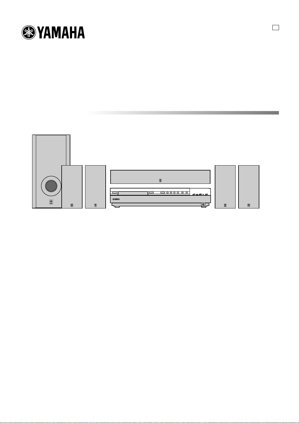
DVD HOME THEATER SOUND SYSTEM
DVX-S100
U
DVX-S100: DVR-S100 + NX-S100S + NX-S100C + SW-S100
OWNER’S MANUAL
IMPORTANT SAFETY INSTRUCTIONS
CAUTION
RISK OF ELECTRIC SHOCK
DO NOT OPEN
CAUTION: TO REDUCE THE RISK OF
ELECTRIC SHOCK, DO NOT REMOVE
COVER (OR BACK). NO USER-SERVICEABLE
PARTS INSIDE. REFER SERVICING TO QUALIFIED
SERVICE PERSONNEL.
• Explanation of Graphical Symbols
The lightning flash with arrowhead symbol, within
an equilateral triangle, is intended to alert you to the
presence of uninsulated “dangerous voltage” within
the product’s enclosure that may be of sufficient
magnitude to constitute a risk of electric shock to
persons.
The exclamation point within an equilateral triangle
is intended to alert you to the presence of important
operating and maintenance (servicing) instructions in
the literature accompanying the appliance.
WARNING
TO REDUCE THE RISK OF FIRE OR ELECTRIC SHOCK,
DO NOT EXPOSE THIS UNIT TO RAIN OR MOISTURE.
1 Read Instructions – All the safety and operating instructions
should be read before the product is operated.
2 Retain Instructions – The safety and operating instructions
should be retained for future reference.
3 Heed Warnings – All warnings on the product and in the
operating instructions should be adhered to.
4 Follow Instructions – All operating and use instructions
should be followed.
5 Cleaning – Unplug this product from the wall outlet before
cleaning. Do not use liquid cleaners or aerosol cleaners.
Use a damp cloth for cleaning.
6 Attachments – Do not use attachments not recommended
by the product manufacturer as they may cause hazards.
7 Water and Moisture – Do not use this product near water –
for example, near a bath tub, wash bowl, kitchen sink, or
laundry tub; in a wet basement; or near a swimming pool;
and the like.
8 Accessories – Do not place this product on an unstable cart,
stand, tripod, bracket, or table. The product may fall,
causing serious injury to a child or adult, and serious
damage to the product. Use only with a cart, stand, tripod,
bracket, or table recommended by the manufacturer, or sold
with the product. Any mounting of the product should
follow the manufacturer’s instructions, and should use a
mounting accessory recommended by the manufacturer.
9 A product and cart combination should be
moved with care. Quick stops, excessive
force, and uneven surfaces may cause the
product and cart combination to overturn.
10 Ventilation – Slots and openings in the cabinet are provided
for ventilation and to ensure reliable operation of the
product and to protect it from overheating, and these
openings must not be blocked or covered. The openings
should never be blocked by placing the product on a bed,
sofa, rug, or other similar surface. This product should not
be placed in a built-in installation such as a bookcase or
rack unless proper ventilation is provided or the
manufacturer’s instructions have been adhered to.
11 Power Sources – This product should be operated only from
the type of power source indicated on the marking label. If
you are not sure of the type of power supply to your home,
consult your product dealer or local power company. For
products intended to operate from battery power, or other
sources, refer to the operating instructions.
12 Grounding or Polarization – This product may be equipped
with a polarized alternating current line plug (a plug having
one blade wider than the other). This plug will fit into the
power outlet only one way. This is a safety feature. If you
are unable to insert the plug fully into the outlet, try
reversing the plug. If the plug should still fail to fit, contact
your electrician to replace your obsolete outlet. Do not
defeat the safety purpose of the polarized plug.
13 Power-Cord Protection – Power-supply cords should be
routed so that they are not likely to be walked on or pinched
by items placed upon or against them, paying particular
attention to cords at plugs, convenience receptacles, and the
point where they exit from the product.
14 Lightning – For added protection for this product during a
lightning storm, or when it is left unattended and unused for
long periods of time, unplug it from the wall outlet and
disconnect the antenna or cable system. This will prevent
damage to the product due to lightning and power-line
surges.
15 Power Lines – An outside antenna system should not be
located in the vicinity of overhead power lines or other
electric light or power circuits, or where it can fall into such
power lines or circuits. When installing an outside antenna
system, extreme care should be taken to keep from touching
such power lines or circuits as contact with them might be
fatal.
16 Overloading – Do not overload wall outlets, extension
cords, or integral convenience receptacles as this can result
in a risk of fire or electric shock.
17 Object and Liquid Entry – Never push objects of any kind
into this product through openings as they may touch
dangerous voltage points or short-out parts that could result
in a fire or electric shock. Never spill liquid of any kind on
the product.
18 Servicing – Do not attempt to service this product yourself
as opening or removing covers may expose you to
dangerous voltage or other hazards. Refer all servicing to
qualified service personnel.
19 Damage Requiring Service – Unplug this product from the
wall outlet and refer servicing to qualified service personnel
under the following conditions:
a) When the power-supply cord or plug is damaged,
b) If liquid has been spilled, or objects have fallen into
the product,
c) If the product has been exposed to rain or water,
CAUTION
d) If the product does not operate normally by following
the operating instructions. Adjust only those controls
that are covered by the operating instructions as an
improper adjustment of other controls may result in
damage and will often require extensive work by a
qualified technician to restore the product to its normal
operation,
e) If the product has been dropped or damaged in any
way, and
f) When the product exhibits a distinct change in
performance - this indicates a need for service.
20 Replacement Parts – When replacement parts are required,
be sure the service technician has used replacement parts
specified by the manufacturer or have the same
characteristics as the original part. Unauthorized
substitutions may result in fire, electric shock, or other
hazards.
21 Safety Check – Upon completion of any service or repairs
to this product, ask the service technician to perform safety
checks to determine that the product is in proper operating
condition.
22 Wall or Ceiling Mounting – The unit should be mounted to
a wall or ceiling only as recommended by the manufacturer.
23 Heat – The product should be situated away from heat
sources such as radiators, heat registers, stoves, or other
products (including amplifiers) that produce heat.
Note to CATV system installer:
This reminder is provided to call the CATV system installer’s
attention to Article 820-40 of the NEC that provides
guidelines for proper grounding and, in particular, specifies
that the cable ground shall be connected to the grounding
system of the building, as close to the point of cable entry as
practical.
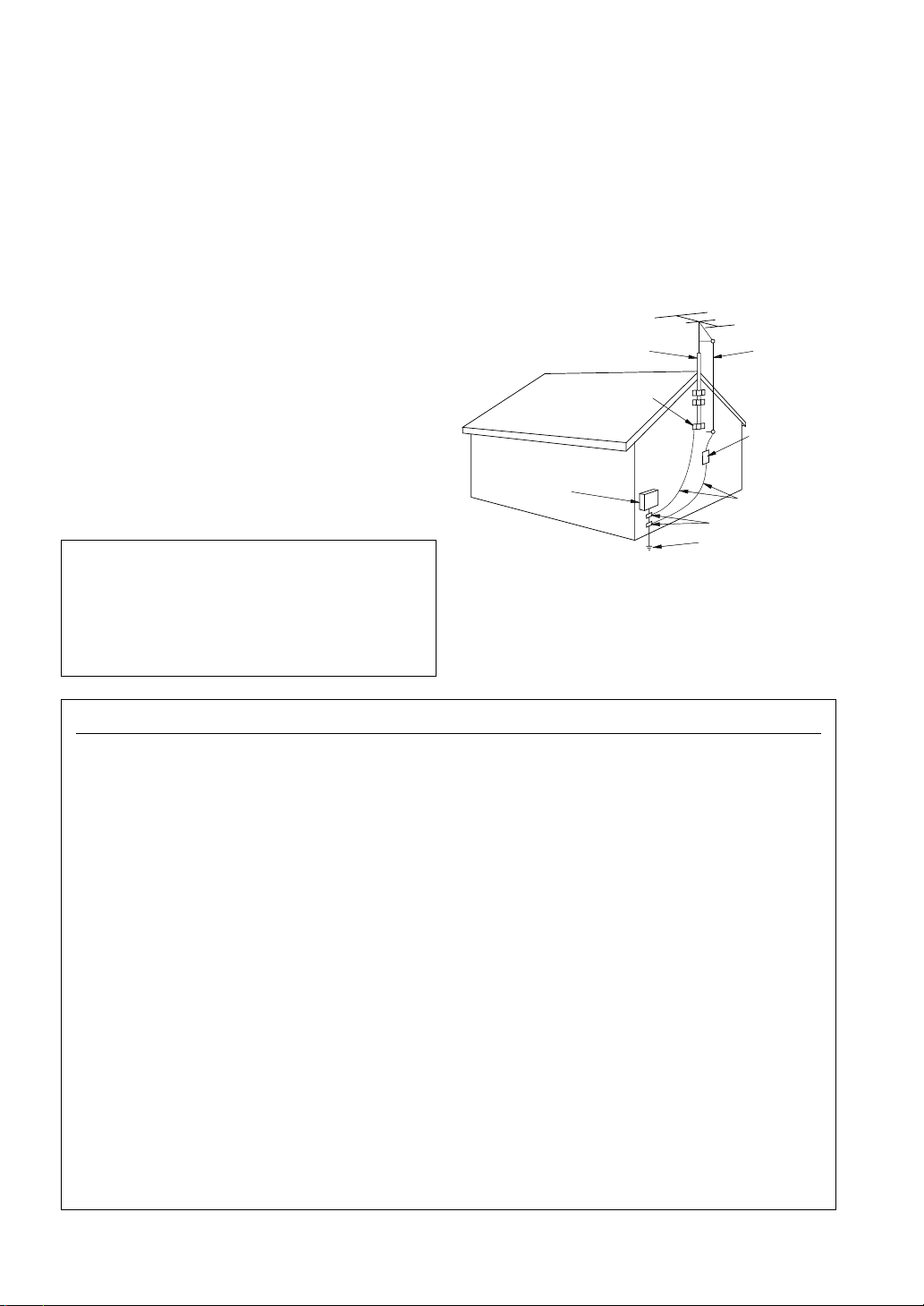
24 Outdoor Antenna Grounding – If an outside antenna or
cable system is connected to the product, be sure the
antenna or cable system is grounded so as to provide some
protection against voltage surges and built-up static charges.
Article 810 of the National Electrical Code, ANSI/NFPA
70, provides information with regard to proper grounding of
the mast and supporting structure, grounding of the lead-in
wire to an antenna discharge unit, size of grounding
conductors, location of antenna discharge unit, connection
to grounding electrodes, and requirements for the
grounding electrode.
EXAMPLE OF ANTENNA GROUNDING
ANTENNA
LEAD IN
WIRE
ANTENNA
DISCHARGE UNIT
(NEC SECTION 810–20)
GROUNDING CONDUCTORS
(NEC SECTION 810–21)
GROUND CLAMPS
ELECTRIC
SERVICE
EQUIPMENT
NEC
– NATIONAL ELECTRICAL CODE
MAST
GROUND
CLAMP
POWER SERVICE GROUNDING
ELECTRODE SYSTEM
(NEC ART 250. PART H)
FCC INFORMATION (for US customers only)
1. IMPORTANT NOTICE : DO NOT MODIFY THIS
UNIT!
This product, when installed as indicated in the
instructions contained in this manual, meets FCC
requirements. Modifications not expressly approved
by Yamaha may void your authority, granted by the
FCC, to use the product.
2. IMPORTANT : When connecting this product to
accessories and/or another product use only high
quality shielded cables. Cable/s supplied with this
product MUST be used. Follow all installation
instructions. Failure to follow instructions could void
your FCC authorization to use this product in the USA.
3. NOTE : This product has been tested and found to
comply with the requirements listed in FCC
Regulations, Part 15 for Class “B” digital devices.
Compliance with these requirements provides a
reasonable level of assurance that your use of this
product in a residential environment will not result in
harmful interference with other electronic devices.
This equipment generates/uses radio frequencies and,
if not installed and used according to the instructions
found in the users manual, may cause interference
harmful to the operation of other electronic devices.
Compliance with FCC regulations does not guarantee
that interference will not occur in all installations. If
this product is found to be the source of interference,
which can be determined by turning the unit “OFF” and
“ON”, please try to eliminate the problem by using one
of the following measures:
Relocate either this product or the device that is being
affected by the interference.
Utilize power outlets that are on different branch (circuit
breaker or fuse) circuits or install AC line filter/s.
In the case of radio or TV interference, relocate/reorient
the antenna. If the antenna lead-in is 300 ohm ribbon
lead, change the lead-in to coaxial type cable.
If these corrective measures do not produce satisfactory
results, please contact the local retailer authorized to
distribute this type of product. If you can not locate the
appropriate retailer, please contact Yamaha Electronics
Corp., U.S.A. 6660 Orangethorpe Ave, Buena Park, CA
90620.
The above statements apply ONLY to those products
distributed by Yamaha Corporation of America or its
subsidiaries.
CAUTION
CAUTION: READ THIS BEFORE OPERATING YOUR UNIT.
1 To assure the finest performance, please read this manual
carefully. Keep it in a safe place for future reference.
2 Install this sound system in a well ventilated, cool, dry, clean
place with at least 10 cm on the top, 10 cm on the left and
right, and 10 cm at the back of DVR-S100, and 20 cm on the
top, 10 cm on the left and right, and 10 cm at the back of
SW-S100 — away from direct sunlight, heat sources,
vibration, dust, moisture, and/or cold.
3 Locate this unit away from other electrical appliances,
motors, or transformers to avoid humming sounds. To
prevent fire or electrical shock, do not place this unit where
it may get exposed to dripping or splashing, and never put
any objects filled with liquids, such as vases, on the top of
the unit.
4 Do not expose this unit to sudden temperature changes from
cold to hot, and do not locate this unit in a environment with
high humidity (i.e. a room with a humidifier) to prevent
condensation inside this unit, which may cause an electrical
shock, fire, damage to this unit, and/or personal injury.
5 Avoid installing this unit in a place where foreign objects
and liquid might fall. It might cause a fire, damage to this
unit and/or personal injury. Do not place the following
objects on this unit:
– Other components, as they may cause damage and/or
discoloration on the surface of this unit.
– Burning objects (i.e. candles), as they may cause fire,
damage to this unit, and/or personal injury.
– Containers with liquid in them, as they may cause
electrical shock to the user and/or damage to this unit.
6 Do not cover this unit with a newspaper, tablecloth, curtain,
etc. in order not to obstruct heat radiation. If the temperature
inside this unit rises, it may cause fire, damage to this unit,
and/or personal injury.
7 Do not plug in this unit to a wall outlet until all connections
are complete.
8 Do not operate this unit upside-down. It may overheat,
possibly causing damage.
9 Do not use force on switches, knobs and/or cords.
10 When disconnecting the power cord from the wall outlet,
grasp the plug; do not pull the cord.
11 Do not clean this unit with chemical solvents; this might
damage the finish. Use a clean, dry cloth.
12 Only voltage specified on this unit must be used. Using this
unit with a higher voltage than specified is dangerous and
may cause fire, damage to this unit, and/or personal injury.
YAMAHA will not be held responsible for any damage
resulting from use of this unit with a voltage other than
specified.
13 To prevent damage by lightning, disconnect the power cord
from the wall outlet during an electrical storm.
14 Take care of this unit so that no foreign objects and/or liquid
drops inside this unit.
15 Do not attempt to modify or fix this unit. Contact qualified
YAMAHA service personnel when any service is needed.
The cabinet should never be opened for any reasons.
16 When not planning to use this unit for long periods of time
(i.e. vacation), disconnect the AC power plug from the wall
outlet.
17 Be sure to read the “TROUBLESHOOTING” section on
common operating errors before concluding that this unit is
faulty.
18 Before moving this unit, press STANDBY/ON to set this
unit in the standby mode, and disconnect the AC power plug
from the wall outlet.
19 VOLTAGE SELECTOR (General model only)
The VOLTAGE SELECTOR on the rear panel of this unit
must be set for your local main voltage BEFORE plugging
into the AC main supply.
Voltages are 220/240 V AC, 50 Hz.
This unit is not disconnected from the AC power source as
long as it is connected to the wall outlet, even if this unit
itself is turned off. This state is called the standby mode. In
this state, this unit is designed to consume a very small
quantity of power.
IMPORTANT
Please record the serial number of this unit in the space
below.
MODEL:
Serial No.:
The serial number is located on the bottom of the unit.
Retain this Owner’s Manual in a safe place for future
reference.
FOR CANADIAN CUSTOMERS
To prevent electric shock, match wide blade of plug to wide
slot and fully insert.
This Class B digital apparatus complies with Canadian ICES-
003.
DANGER
Visible laser radiation when open. Avoid direct exposure to
beam.
When this unit is plugged to the wall outlet, do not place your
eyes close to the opening of the disc tray and other openings to
look into inside.
The laser component in this product is capable of emitting
radiation exceeding the limit for Class 1.
The name plate is located on the bottom of the unit.
We Want You Listening For A Lifetime
YAMAHA and the Electronic Industries Association’s Consumer
Electronics Group want you to get the most out of your
equipment by playing it at a safe level. One that lets the sound
come through loud and clear without annoying blaring or
distortion – and, most importantly, without affecting your
sensitive hearing.
CAUTION
Since hearing damage from loud sounds is often
undetectable until it is too late, YAMAHA and the
Electronic Industries Association’s Consumer
Electronics Group recommend you to avoid
prolonged exposure from excessive volume levels.

CONTENTS
INTRODUCTION
FEATURES .......................................................................... 2
CHECKING THE ACCESSORIES ................................... 3
INSTALLING BATTERIES IN THE REMOTE
CONTROL ........................................................................... 3
CONTROLS AND FUNCTIONS ....................................... 4
Front panel ......................................................................... 4
Remote control (AMP mode) ............................................ 6
Front panel display (left) ................................................... 8
Front panel display (right) ................................................. 9
PREPARATION
PREPARATION STEPS ................................................... 10
SPEAKER SETUP ............................................................. 11
Speaker placement ........................................................... 11
Installing the speakers ..................................................... 12
CONNECTIONS ................................................................ 14
Connecting TV and audio/video components ................. 14
Connecting the antennas .................................................. 16
Connecting the speakers .................................................. 17
Connecting to an external amplifier ................................ 19
Connecting the AC power cord ........................................ 19
Turning on the power....................................................... 19
ADJUSTING SPEAKER OUTPUT LEVELS ................ 20
Using the test tone ........................................................... 20
USING BASIC FUNCTIONS
BASIC PLAYBACK .......................................................... 21
Basic operations ............................................................... 21
Selecting a sound field program ...................................... 23
RECORDING .................................................................... 28
PLAYING A DISC
DISC INFORMATION ..................................................... 29
Types of disc that this unit can play ................................ 29
Region management information .................................... 29
Notes about handling discs .............................................. 29
MP3 playback .................................................................. 30
REMOTE CONTROL (DVD MODE) ............................. 31
PLAYING A DISC ............................................................. 32
Basic operation ................................................................ 32
ON-SCREEN MENU ......................................................... 34
Operating menu bar ......................................................... 34
Icons for disc menu ......................................................... 35
Icons for player menu ...................................................... 36
USING MULTIPLE FUNCTIONS .................................. 38
Using a disc’s menu ......................................................... 38
Enhancing video quality
[U.S.A. and Canada models only] ................................... 38
DVD-Audio features........................................................ 39
Enhancing audio quality (DISC DIRECT) ...................... 40
Switching audio tracks, subtitles and angles ................... 41
All group play .................................................................. 42
Programmed play ............................................................. 42
Random play .................................................................... 43
Bookmarks ....................................................................... 44
Repeat play ...................................................................... 45
Repeat A-B ...................................................................... 46
SETUP MENU ................................................................... 47
Operating the setup menu ................................................ 47
Summary of settings ........................................................ 48
Ratings ............................................................................. 51
PCM down conversion..................................................... 51
Speaker settings ............................................................... 52
TUNING
TUNING ............................................................................. 54
Automatic and manual tuning ......................................... 54
Presetting stations ............................................................ 55
Tuning in to a preset station............................................. 56
Exchanging preset stations .............................................. 56
REMOTE CONTROL FEATURES
OPERATING OTHER COMPONENTS USING THE
REMOTE CONTROL....................................................... 57
Setting the manufacturer code ......................................... 57
ADJUSTMENTS
SET MENU ......................................................................... 59
List of SET MENU items ................................................ 59
Adjusting the items on the SET MENU .......................... 59
1 SPEAKER SET (speaker mode settings) .................... 60
2 LFE LEVEL ................................................................ 61
3 SP DLY TIME (speaker delay time) ........................... 62
4 D. RANGE (dynamic range) ....................................... 62
5 L/R BALANCE (balance of the front left and right
speakers) ...................................................................... 62
6 HP TONE CTRL (headphone tone control) ................ 62
7 I/O ASSIGN (input assignment) ................................. 63
8 INPUT MODE (initial input mode) ............................ 63
9 SP/PRE OUT (output source settings) ......................... 63
ADJUSTING THE LEVEL OF THE EFFECT
SPEAKERS ........................................................................ 64
CHANGING THE PARAMETER SETTINGS FOR DSP
PROGRAMS ...................................................................... 65
Adjusting the delay time .................................................. 65
Adjusting the parameter settings for PRO LOGIC II
Music ............................................................................... 66
APPENDIX
TROUBLESHOOTING .................................................... 67
GLOSSARY ....................................................................... 72
SPECIFICATIONS ............................................................ 75
English
1

FEATURES
The DVX-S100 is the Home Theater Sound System that delivers a powerful and realistic sound experience like that
found in a movie theater just by combining the unit with the TV.
The newest DSP programs will enhance the power and realism of various sources, from movies to concerts, and
sporting events. Also, the Silent Cinema program allows you to enjoy the sound field even through the headphones.
Since the DVX-S100 consists of a DVD Audio/Video receiver, a center speaker, front speakers, rear speakers and a
subwoofer, you can enjoy stronger bass and surround effects as well as a good balance throughout the speakers.
Moreover, the One-touch connection of the speaker connectors designed exclusively for this unit allows you to easily
connect the speakers.
◆ Built-in 5-channel power amplifier
◆ DVD-AUDIO/VIDEO, CD, VCD, MP3, CD-R/
RW playback
◆ Dolby Pro Logic/Dolby Pro Logic II decoder
◆ Dolby Digital/Dolby Digital + Matrix 6.1
decoder
◆ DTS/DTS + Matrix 6.1 decoder
◆ Sophisticated FM/AM tuner
◆ CINEMA DSP: Combination of YAMAHA DSP
technology and Dolby Pro Logic, Dolby Digital
or DTS
■ About this manual
• y indicates a tip for your operation.
• Some operations can be performed by using the buttons
on either the main unit or the remote control. In this
case, the operations performed by using the remote
control are described in this manual.
• This manual is printed prior to production. Design and
specifications are subject to change in part for the
reason of the improvement in operativity ability, and
others. In this case, the product has priority.
• Some of the illustrations and names of the package
contents etc written in this manual may differ from the
actual products and the names written on the package
etc.
◆ Virtual CINEMA DSP
◆ SILENT CINEMA DSP
◆ Easy connection of the center speaker, front
speakers and rear speakers using special speaker
connectors designed exclusively for this unit
◆ Multi-function remote control which can also be
used for other audio/video components of certain
manufacturers
Manufactured under license from Dolby Laboratories.
“Dolby”, “Pro Logic”, and the double-D symbol are
trademarks of Dolby Laboratories.
“DTS” and “DTS Digital Surround” are registered
trademarks of Digital Theater Systems, Inc.
(U.S.A. and Canada models)
2
“DCDi” is a trademark of Faroudja, a division of Sage
Inc.
This product incorporates copyright protection
technology that is protected by method claims of certain
U.S. patents and other intellectual property rights owned
by Macrovision Corporation and other rights owners. Use
of this copyright protection technology must be
authorized by Macrovision Corporation, and is intended
for home and other limited viewing uses only unless
otherwise authorized by Macrovision Corporation.
Reverse engineering or disassembly is prohibited.
3
INTRODUCTION
English
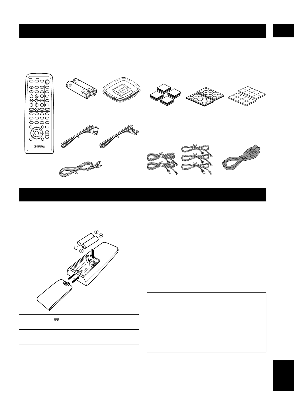
CHECKING THE ACCESSORIES
Check your package to make sure it contains the following items.
DVR-S100
Remote control
TV
CH
INPUT
TUNER
MUTE CD–R
VCR
VIDEO 2
VIDEO 1
MD
AV
SLEEP
POWER
TV MODE
POWER
VOL
REC
AUDIO
SUBTITLE
SHIFT
CODE SET
1
HALL2JAZZ
SETUP
3
ROCK
ANGLE
4
ENTERTAINMENT
MARKER
5
SPORTS6MONO MOVIE
PLAY MODE
7
MOVIE 1
REPEAT
8
MOVIE 2
A–B
DVDCDAMP
9
/DTS
TOP MENU
LEVEL
MENU
SET MENU
TEST
ON SCREEN
B. BOOST
RETURN
0
SELECT
>
–
10
MATRIX 6.1
GROUP
CANCEL
STEREO
PAGE
MUTE
VOL
ABCDE
ENTER
PRESET
CH
PRESET
CH
Batteries (x2)
(AA, R06, UM-3)
AM loop antenna
Indoor FM antenna
(U.S.A., Canada and
General models)
(Europe, U.K. and
Australia models)
NX-SW100 (NX-S100S x4, NX-S100C, SW-S100)
Fasteners (4 sets)
for the center
speaker
Pads
(2 sets: 16 pieces)
Speaker cables
(for the rear speakers: 15m (x2),
for the front/center speaker:
5m (x3))
System connector
cable (5m x 1)
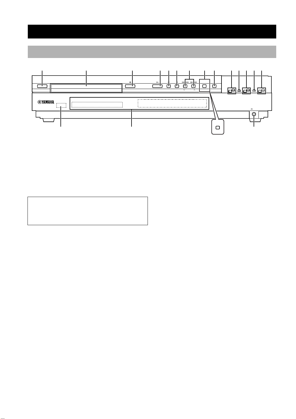
INSTALLING BATTERIES IN THE REMOTE CONTROL
Insert the batteries in the correct direction by aligning the
+ and – marks on the batteries with the polarity markings
(+ and –) inside the battery compartment.
1 Press the part and slide off the battery
compartment cover.
2 Insert the two batteries (AA, R06, UM-3 type)
with + and – oriented properly.
3 Slide the cover back on so that it snaps into
place.
1
3
2
■ Notes on batteries
• Change all of the batteries if you notice a decrease in
the operating range of the remote control.
• Do not use old batteries together with new ones.
• Do not use different types of batteries (such as alkaline
and manganese batteries) together. Read the packaging
carefully as these different types of batteries may have
the same shape and color.
• If the batteries have leaked, dispose of them
immediately. Avoid touching the leaked material or
letting it come into contact with clothing, etc. Clean the
battery compartment thoroughly before installing new
batteries.
Preserving the manufacturer code
Replace batteries early before they become unusable.
The manufacturer code set by the user will be
preserved for about two minutes when batteries run
out or when they are removed. Note that the
manufacturer code setting may be lost if more than
two minutes elapses. Also, if you press any button on
the remote control accidentally while replacing
batteries, the manufacturer code will be lost.
Non-skid pads
(2 sets: 16 pieces)
Video pin cable
Front panel
CONTROLS AND FUNCTIONS
12 3456890qwer
STANDBY/ON
A/B/C/D/E
t
1 STANDBY/ON
Turns this unit on, or set it to the standby mode. When
you turn this unit on, you will hear a click and there will
be a 4 to 5-second delay before this unit can reproduce
sound.
Standby mode
In this mode, this unit will consume a small amount of
power in order to receive infrared-signals from the
remote control.
2 Disc tray
The disc you play is loaded on this tray.
3 v
Press to open and close the disc tray.
4 w
Press to start playback.
5 a (A/B/C/D/E)
(DVD mode)
Press to stop playback.
(Tuner mode)
Selects preset station groups A to E.
6 d (PRESET/BAND)
(DVD mode)
Press to pause.
(Tuner mode)
Switches the reception band between FM and AM and
also the mode between the tuning mode and the preset
mode.
y
7 t/e, r/y (d PRESET/TUNING /
PRESET/TUNING u)
(DVD mode)
Each time these buttons are pressed, the disc begins
playing from the beginning of the track you select. When
you keep pressing the buttons, the disc searches forward
or backward.
(Tuner mode)
Selects preset station numbers 1 to 8 when the colon (:)
appears in the front panel display.
Selects the tuning frequency when the colon (:) does not
appear.
8 PROGRESSIVE (MEMORY) (U.S.A. and
Canada models)
(DVD mode)
Switches between progressive video output and interlace
video output.
(Tuner mode)
Stores the current station in the memory.
MEMORY (U.K., Europe, Australia and
General models)
(Tuner mode)
Stores the current station in the memory.
9 DISC DIRECT (AUTO/MAN’L)
(DVD mode)
Changes the modes of DISC DIRECT function.
(Tuner mode)
Switches the tuning mode between automatic and manual.
7
PROGRESSIVE
DISC DIRECT
PRESET/BAND PRESET/TUNING MEMORY
(U.K., Europe, Australia and General models)
AUTO/MAN’L
MEMORY
SILENT
u
4

0 INPUT H/G
Selects the input source you want to listen to or watch.
q INPUT MODE
Sets the priority for the types of input signals (AUTO,
DTS, ANALOG) to receive when one component is
connected to two or more input jacks.
w DSP H/G
Selects the DSP program.
e STEREO
Switches between normal stereo and DSP effect
reproduction. When STEREO is selected, 2-channel
signals are directed to the front left and right speakers
without effect sounds.
r VOLUME +/–
Controls the output level of all audio channels.
This does not affect the recording (Rec) level.
t Remote control sensor
Receives signals from the remote control.
y Front panel display
Shows information about the operational status of this
unit.
CONTROLS AND FUNCTIONS
INTRODUCTION
SILENT
u
Allows you enjoy DSP effect for private listening with
headphones. When you connect headphones, no signals
are output to the speakers.
English
5
CONTROLS AND FUNCTIONS
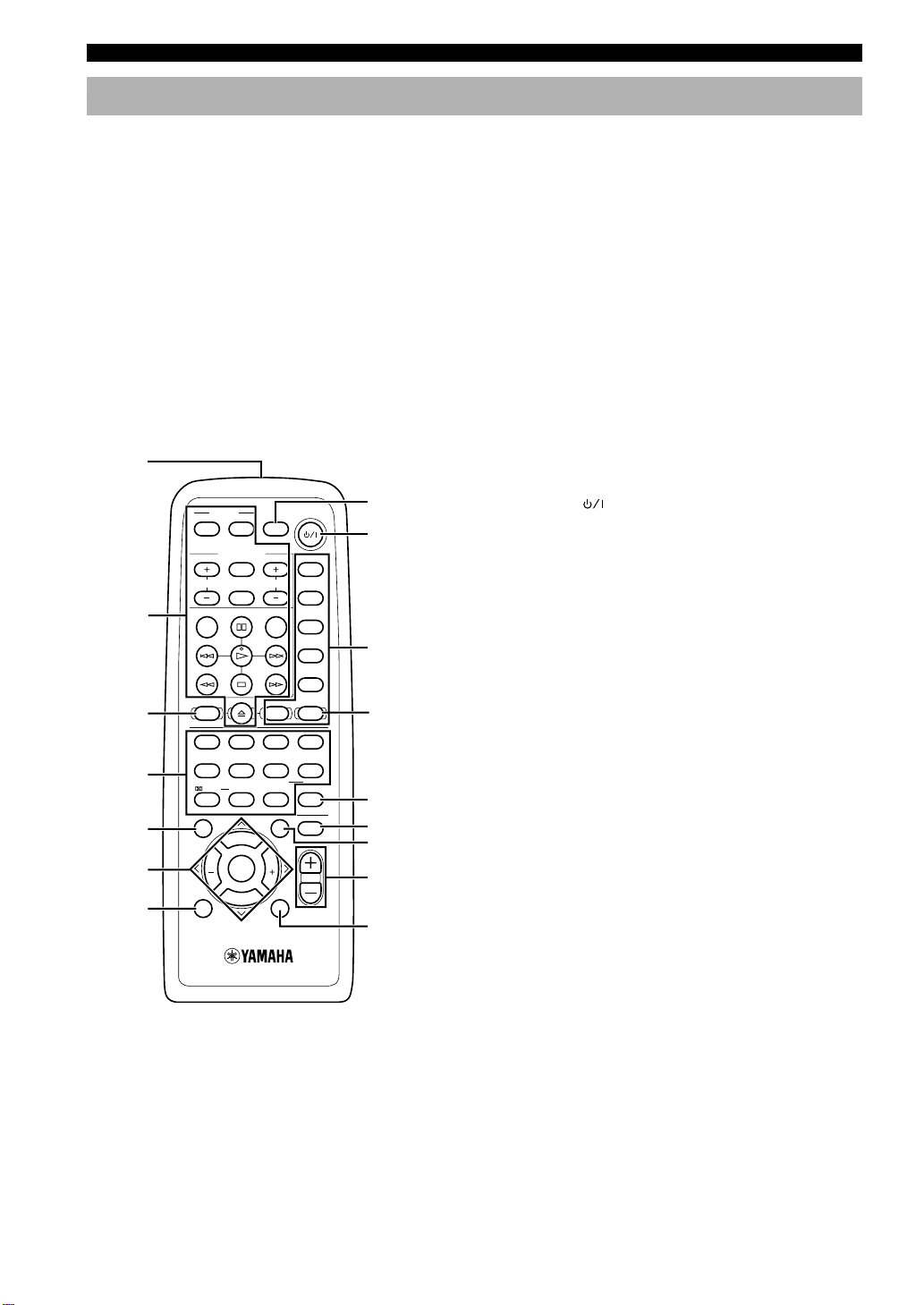
Remote control (AMP mode)
This section explains the function of each button on the
remote control when you operate this unit as an amplifier,
not as a tuner or a DVD player. Make sure that the AMP
mode is selected before starting operation.
Refer to “REMOTE CONTROL (DVD MODE)” on page
31 for the details about the functions of the remote
control when you control this unit in the DVD mode.
Also, refer to “OPERATING OTHER COMPONENTS
USING THE REMOTE CONTROL” on pages 57 and 58
for the details about its functions when controlling other
components connected to this unit.
y
• The buttons on the remote control whose names are written in
purple are operation buttons when you operate this unit in the
AMP mode.
1
8
9
0
AMP
q
w
e
r
t
2
3
4
5
6
7
POWER
TV
AV
TV MODE
INPUT
CH
MUTE CD–R
SUBTITLE
REC
CODE SET
SHIFT
HALL2JAZZ
1
SETUP
SPORTS6MONO MOVIE
5
PLAY MODE
/DTS
SELECT
9
0
TOP MENU
LEVEL
SET MENU
PRESET
CH
ENTER
PRESET
TEST
B. BOOST
ON SCREEN
SLEEP
VOL
AUDIO
DVDCDAMP
ROCK
ANGLE
MOVIE 1
REPEAT
MATRIX 6.1
>
–
GROUP
MENU
CH
RETURN
3
7
10
ABCDE
POWER
TUNER
MD
VCR
VIDEO 2
VIDEO 1
ENTERTAINMENT
4
MARKER
MOVIE 2
8
A–B
STEREO
CANCEL
PAGE
MUTE
VOL
3 CODE SET
Used when setting up the manufacturer code.
4 DSP program buttons
Select DSP programs for the AMP position. Press a
button repeatedly to select a DSP program within that
group.
5 LEVEL
Selects the effect speaker channel to be adjusted.
6 Cursor buttons (j, i, u, d)/ENTER
Select SET MENU items and change the settings on the
SETUP menu etc.
7 TEST
Outputs the test tone to adjust the speaker levels.
8 SLEEP
Sets the sleep timer.
9 POWER (
)
Turns this unit on, or set it to the standby mode.
0 Input selector buttons/AMP
Select the input source and set the remote control to
operate the selected source component. Sets the remote
control to the AMP mode for controlling this unit.
q STEREO
Switches between normal stereo and DSP effect
reproduction. When STEREO is selected, 2-channel
signals are directed to the front left and right speakers
without effect sounds and all Dolby Digital and DTS
signals (except the LFE channel) are mixed down to the
front left and right speakers.
w MUTE
Mutes the sound. Press again to restore the audio output
to the previous volume level.
e SET MENU
Selects the SET MENU mode.
r VOL +/–
Increases or decreases the volume level.
(U.S.A. model)
1 Infrared window
Outputs infrared control signals. Aim this window at the
component you want to operate.
2 Basic operation buttons
Used to operate the components selected with input
selector buttons.
6
t B. BOOST
Turns BASS BOOST function on or off.

■ Using the remote control
Approximately 6 m (20 feet)
30° 30°
Handling the remote control
• Do not spill water or other liquids on the remote
control.
• Do not drop the remote control.
• Do not leave or store the remote control in the
following types of conditions:
– high humidity or temperature such as near a heater,
stove or bath;
– dusty places; or
– in places subject to extremely low temperatures.
CONTROLS AND FUNCTIONS
INTRODUCTION
English
7
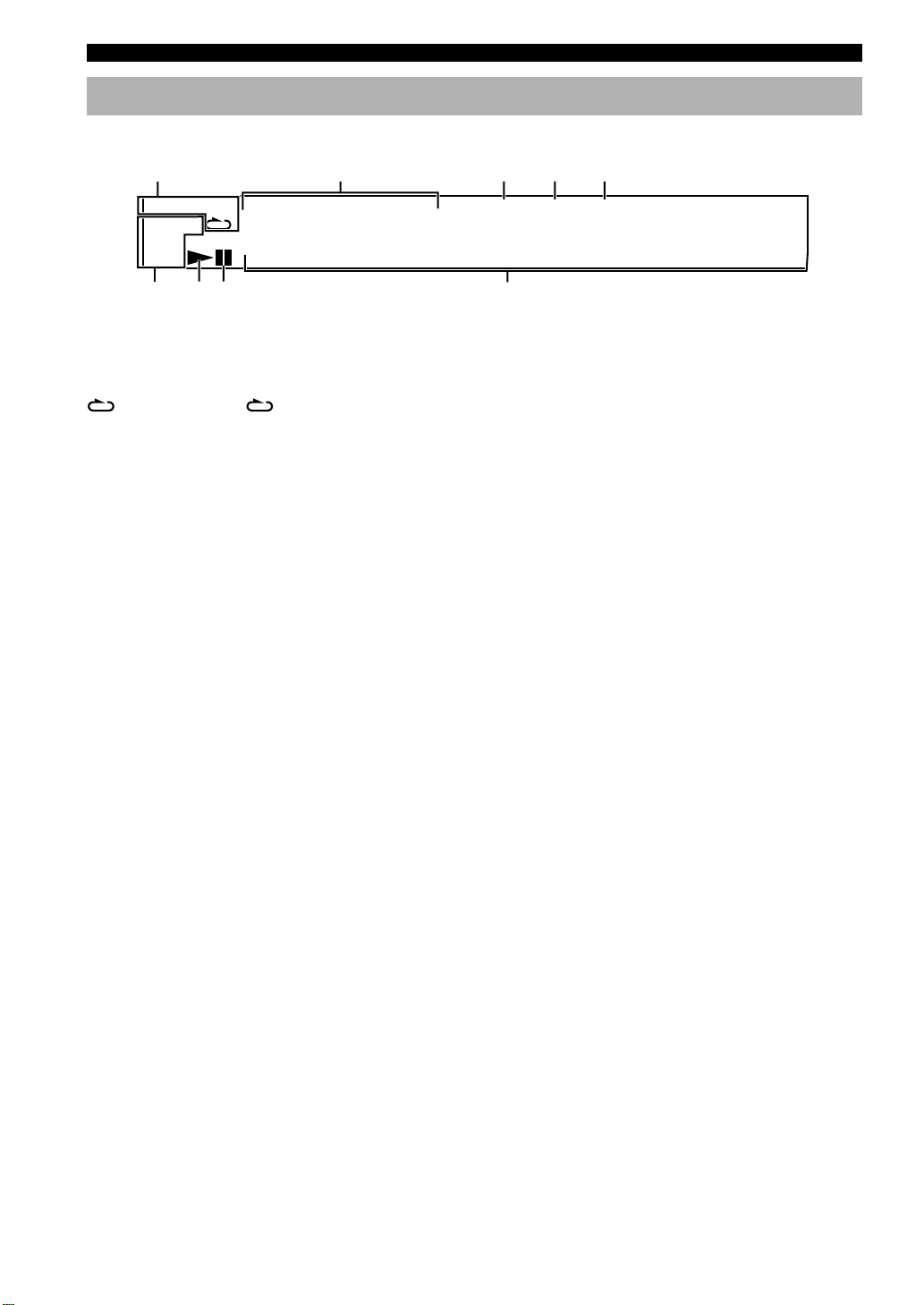
CONTROLS AND FUNCTIONS
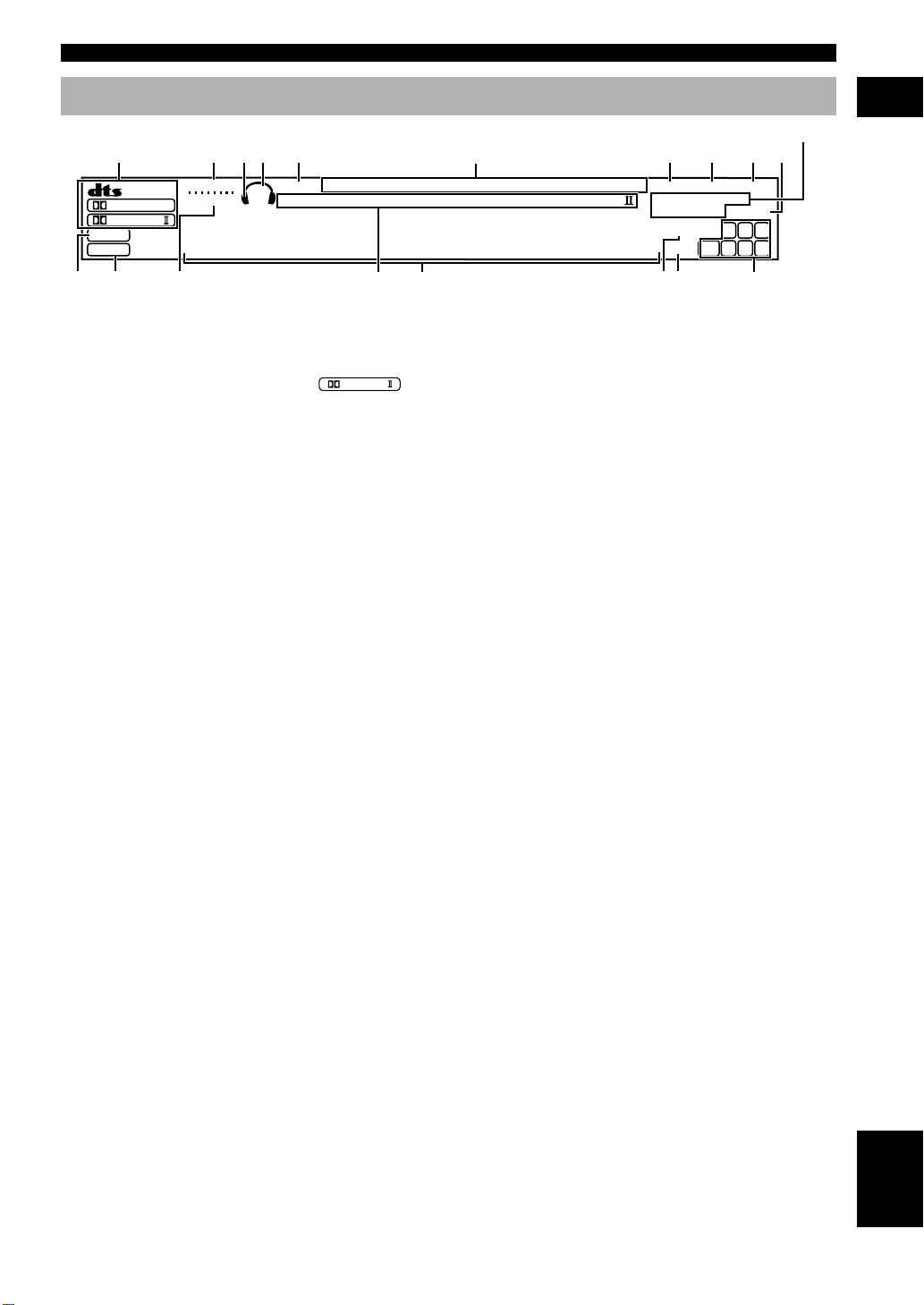
Front panel display (left)
This front panel display mainly displays the information related to the playback of discs.
1
PGM RND
–
GROUP TITLE TRACK CHAP D.MIX P.PCM MLT.CH
AB
2345
DVD V CD
VIDEO
AUDIO
768 9
1 Play mode indicators
PGM: Programmed play / RND: Random play /
: Repeat play / A-B : Repeat A-B
2 Mode type indicators
GROUP: Group mode / TITLE: Title mode /
TRACK: Track mode / CHAP: Chapter mode
3 D.MIX (Down Mix)
Lights up when the currently playing multi-channel audio
track is mixed down into 2-channel.
4 P.PCM (Packed PCM)
Lights up while a P.PCM signal is input.
5 MLT.CH (Multi Channel)
Lights up while a multi-channel signal is output.
888888888888
6 Disc type indicators
Indicates the type of disc. For example, DVD and AUDIO
lights up when playing a DVD-Audio disc.
7 w
Lights up during playback. Blinks while resume function
is working.
8 d
Lights up while playback is paused.
9 Multi-information display (left)
Shows various information such as title, chapter or track
number, elapsed playing time etc.
8
Front panel display (right)
12345
DIGITAL
PRO LOGIC
DSP
PCM
MATRIX
VIRTUAL
B. BOOST
/
88888888888888
SILENT
SP
PRE
DVD/CD VIDEO 1VIDEO 2 VCR
MOVIE THTR DTS
12
ENTERTAINMENT
r
6
MD/CD–R TUNER
DOLBY DIGITALPRO LOGIC
CONTROLS AND FUNCTIONS
(U.K. and Europe models only)
7890
STEREO
AUTO
PS PTY RT CT
PTY HOLD
SLEEP
dB
MUTE
ms
MEMORY
L
LFE
RL RC RR
TUNED
C R
iuytewq
o
INTRODUCTION
1 Decoder indicators
Lights up when the t, g,
PRO LOGIC
or
/
MATRIX are activated.
2 VIRTUAL indicator
Lights up in the virtual cinema DSP mode.
3 Headphones indicator
Lights up when headphones are connected.
4 SP/PRE indicator
The indicator of the item selected in “9 SP/PRE OUT” on
the SET MENU lights up. (But it does not light up when
headphones are connected.)
5 SILENT indicator
Lights up when headphones are connected while the
digital sound field processor is on.
6 Input source indicator
Shows the current input source with a cursor.
7 STEREO indicator
Lights up when this unit is receiving a strong signal for an
FM stereo broadcast while the “AU TO” indicator is lit.
8 AUTO indicator
Shows that this unit is in the automatic tuning mode.
9 TUNED indicator
Lights up when this unit is tuned to a station.
0 MEMORY indicator
Flashes to show a station can be stored.
q DSP indicator
Lights up when you select DSP programs.
w v indicator
Lights up when this unit is reproducing PCM (pulse code
modulation) digital audio signals.
e B. BOOST indicator
Lights up when BASS BOOST is ON. (But it does not
light up when headphones are connected.)
r DSP program indicators
The name of the selected DSP program lights up when
the ENTERTAINMENT, MOVIE THEATER 1, MOVIE
THEATER 2 or V/DTS SURROUND DSP program is
selected.
t Multi-information display (right)
Shows the current DSP program name and other
information when adjusting or changing settings.
y SLEEP indicator
Lights up while the sleep timer is on.
u MUTE indicator
Flashes while the MUTE function is on.
i Input channel indicator
Indicates the channel components of input signals being
received.
o RDS indicator (U.K. and Europe models)
The name(s) of the RDS data offered by the currently
received RDS station light(s) up.
PTY HOLD indicator lights up while searching for
stations in the PTY SEEK mode.
English
9
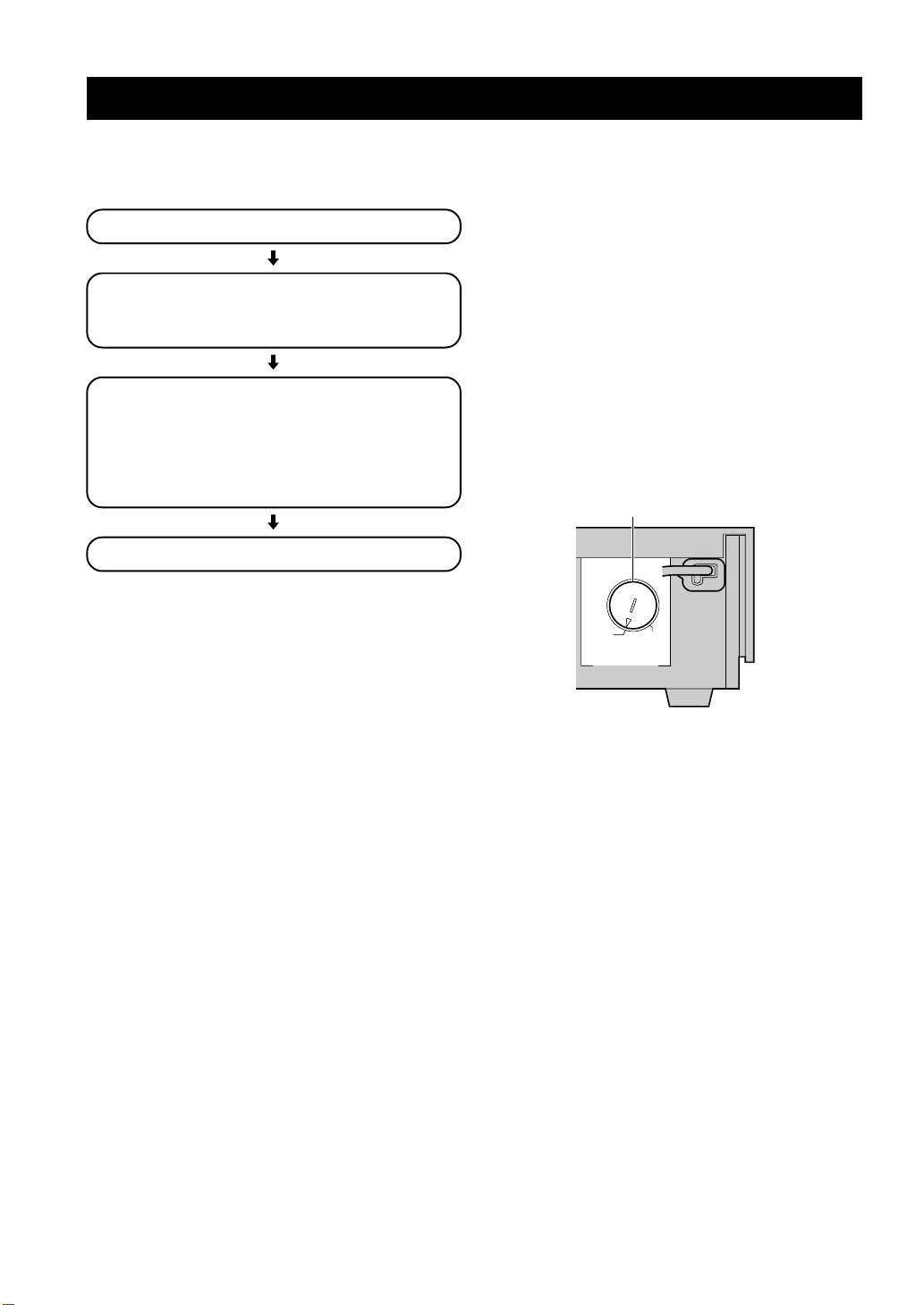
PREPARATION STEPS
In order to enjoy sound and video images with this sound
system, follow the procedures as described below. See
each page for details.
Installing batteries in the remote control (P.3)
Speaker setup (P.11)
• Speaker placement (P.11)
• Installing the speakers (P.12)
Connections (P.14 – 19)
• Connecting TV and audio/video components (P.14)
• Connecting the antennas (P.16)
• Connecting the speakers (P.17)
• Connecting the AC power cord (P.19)
• Turning on the power (P.19)
Adjusting speaker output levels (P.20)
Before connecting components
• Do not connect this unit or other components to the
mains power until all connections between the
components have been completed.
• Be sure all connections are made correctly, that is to
say, L (left) to L, R (right) to R, “+” to “+” and “–” to
“–”. Some components require different connection
methods and have different jack names. Refer to the
operation instructions for each component to be
connected to this unit.
• Insert the plugs properly. The speakers may not output
any sound or may output noise if they are not inserted
properly.
• The name of jack corresponds to input selector.
• The VOLTAGE SELECTOR on the rear panel of this
unit must be set for your local main voltage BEFORE
plugging into the AC main supply. Voltages are
220/240 V AC, 50 Hz. (General model)
VOLTAGE SELECTOR
240V 220V
VOLTAGE SELECTOR
(General model)
After connecting components
• Check them again to make sure they are correct.
10
SPEAKER SETUP
This unit has been designed to provide the best soundfield quality with a 5-speaker system, using front left and
right speakers, rear left and right speakers and a center
speaker.
The front speakers are used for the main source sound
plus effect sounds. The rear speakers are used for effect
and surround sounds. The center speaker is for the center
sounds (dialog, vocals, etc.).
Notes
• If you do not use any of effect speakers (rear and/or center),
change the settings of SPEAKER SET items at the SET MENU
(p.60) to designate the signals to other terminals you connect
speakers to.
• If you use speakers (with different tonal qualities) instead of
the included speakers, the tone of a moving human voice and
other types of sound may not shift smoothly. We recommend
that you use speakers from the same manufacturer or speakers
with the same tonal quality.
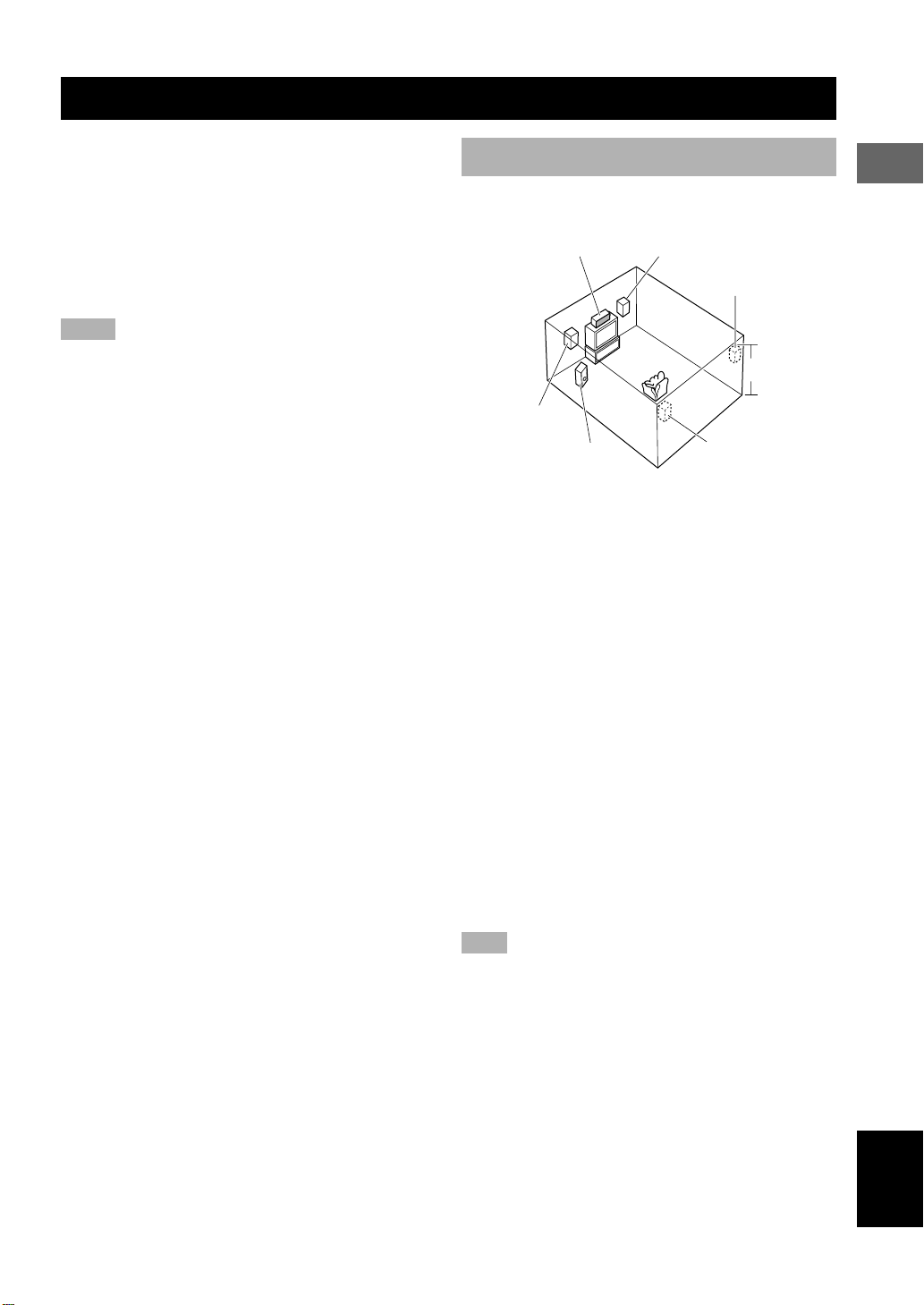
Speaker placement
Refer to the following diagram when you place the
speakers.
Center speaker Front speaker (R)
Rear speaker (R)
1.8 m (6 feet)
Front speaker (L)
Subwoofer
Front speakers
Place the front left and right speakers an equal distance
from the ideal listening position. The distance between
each speaker and each side of the video monitor should
also be the same.
Center speaker
Align the front face of the center speaker with the front
face of your video monitor. Place the speaker as close to
the monitor as possible (such as directly over or under the
monitor) and centrally between the front speakers.
Rear speakers
Place these speakers behind your listening position,
facing slightly inwards, nearly 1.8 m (6 feet) above the
floor.
Subwoofer
The position of the subwoofer is not so critical, because
low bass sounds are not highly directional. But it is better
to place the subwoofer near the front speakers. Turn it
slightly toward the center of the room to reduce wall
reflections.
Note
• Although the speaker system in this unit is magnetically
shielded, it may still affect the color on the television monitor
when using this unit near the television. Adjust the relative
positions of this unit and the television if this happens.
Rear speaker (L)
PREPARATION
English
11
SPEAKER SETUP
Installing the speakers
■ Placing the center speaker
Place the speaker on TV whose top is flat or on the floor
under the TV or inside the TV rack so that it is stabilized.
When placing the speaker on top of the TV, to prevent the
speaker from falling down, put the provided fasteners at
four points on the bottom of the speaker and the top of the
TV.
Fastener
Peel off the
seal
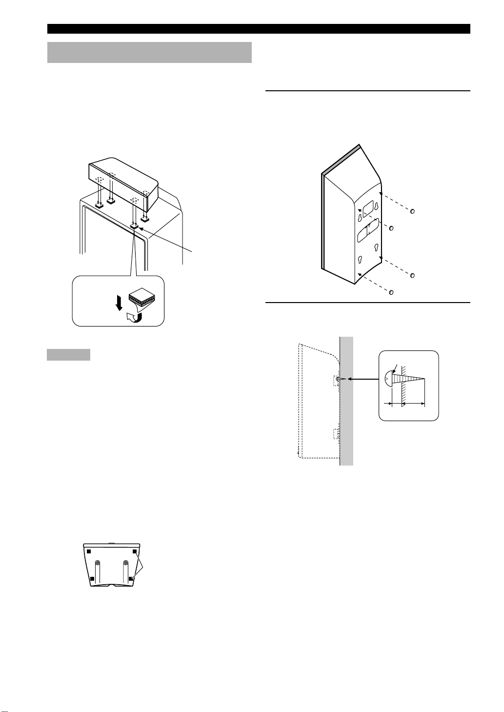
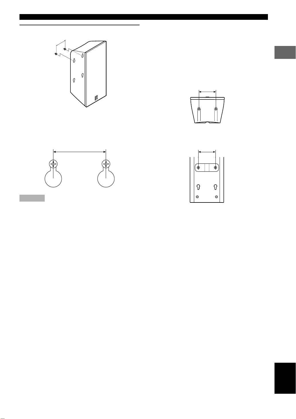
■ Mounting the front and rear
speakers
When mounting the front and rear speakers on a wall, use
the holes on the speakers’ back panels.
1 Put the provided pads at the four corners on
the rear of the front and rear speakers to
prevent the front and rear speakers from
moving by vibrations.
2 Fasten screws into a firm wall or wall
support as shown below.
Cautions
• Do not place the speaker on top of the TV whose area is
smaller than the bottom area of the speaker. If placed, the
speaker may drop out causing an injury to you.
• Do not place the speaker on top of the TV with an inclination.
• Do not touch the adhesive surface after peeling off the seal as
this will weaken its adhesive strength.
• Thoroughly wipe clean the surface where the fastener is to be
applied. Note that adhesive strength is weakened if the surface
is dirty, oily or wet and that this may cause the center speaker
to drop.
■ Placing the front and rear
speakers
When placing the front and rear speakers on a flat
surface, attach the included non-skid pads to the corners
on the bottom of the speakers as shown below. This
prevents the speakers from sliding around.
Non-skid pads
Diam. 3.5 to 4 mm
Min.
20 mm
6 mm
Tapping screw
(Available at the
hardware store)
12
SPEAKER SETUP
3 Hang the holes on the protruding screws.
60 mm
• Make sure that the screws are securely caught by
the narrow parts of the holes.
• You can use the lower holes on the rear of the
front/rear speakers.
60 mm
■ If you want to mount a speaker
on a commercially available
speaker stand (for the front/rear
speakers)
The screw holes (at an interval of 60 mm) on the bottom
and the rear of the speaker can be used to mount the
speaker on a speaker stand.
* Those screw holes can be used with M4 screws only.
60 mm
Front/rear speaker
(bottom)
60 mm
PREPARATION
Cautions
• Each speaker weighs 1.1 kg (2 lbs. 6 oz.). Do not mount them
on thin plywood or a wall with soft surface material. If
mounted, the screws may come out of the flimsy surface and
the speakers may fall. This damages the speakers or causes
personal injury.
• Do not install the speakers to a wall with nails, adhesives, or
any other unstable hardware. Long-term use and vibrations
may cause them to fall.
• To avoid accidents resulting from tripping over loose speaker
cables, fix them to the wall.
• Select a proper position on the wall to mount the speaker so
that no one will injure his/her head or face.
Front/rear speaker
(rear)
English
13
14
CONNECTIONS
Connecting TV and audio/video components
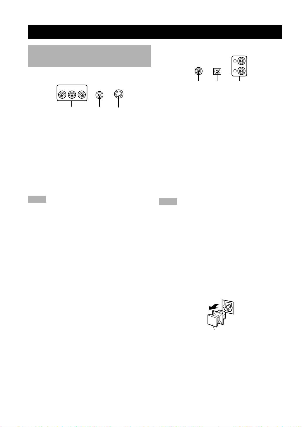
■ Types of video jacks
1 COMPONENT VIDEO jacks (U.S.A., Canada,
Australia and General models)
Transmit color difference (PB/CB, PR /CR) and luminance
separately and provide the best quality picture.
2 VIDEO jack
Conventional composite video signal.
3 S VIDEO jack
Transmits color and luminance separately and achieves
high-quality color reproduction.
Notes
• Each type of video jack works independently. Signals input
through the composite video and S video jacks are only output
through the corresponding composite video and S video jacks.
• When you connect this unit to a video monitor, a video
component and a recording component, connect the same types
of jack, for example, the video jack on this unit to the video
jack on the video component.
• The description of the component video jacks may differ
depending on the component (e.g. Y, CB, CR/Y, PB, PR/Y, B-Y,
R-Y etc.). When using these jacks, refer also to the operation
instructions for the component being connected.
• Do not connect this unit to a video monitor through a video
cassette recorder. If you do so, the picture may not be played
back properly due to the copyright protection technology
incorporated in this unit.
• When progressive output (p.38) is selected in the DVD mode,
video signals are only output from the component video jacks.
321
PR PB Y
■ Types of audio jacks
1 COAXIAL jack
Connects a coaxial pin cable and provides the better
quality sound than analog audio jacks.
2 OPTICAL jack
Connects an optical fiber cable and provides the better
quality sound than analog audio jacks.
3 Analog audio jacks
Connect an audio pin cable.
y
• 1 and 2 are digital jacks.
• You can use the digital jacks to input PCM, Dolby Digital and
DTS bitstreams.
• All digital input jacks are acceptable for 96-kHz sampling
digital signals.
Notes
• Digital output jack and analog OUT (Rec) jacks are
independent. Only digital signals are output from digital output
jack and analog signals from OUT (Rec) jacks.
• The OPTICAL jacks on this unit conform to the EIA standard.
If you use an optical cable that does not conform to this
standard, this unit may not function properly.
• Once you have connected a recording component to this unit,
keep its power turned on while using this unit. If the power is
off, this unit may distort the sound from other components.
Anti-dust cap
Remove the cap covering the OPTICAL jacks when
connecting an optical cable. Safely store the cap and
always re-insert it in the terminal when the terminal is not
in use. (This cap prevents the entrance of dust.)
1 23
L
R
Anti-dust cap
15
CONNECTIONS
PREPARATION
English
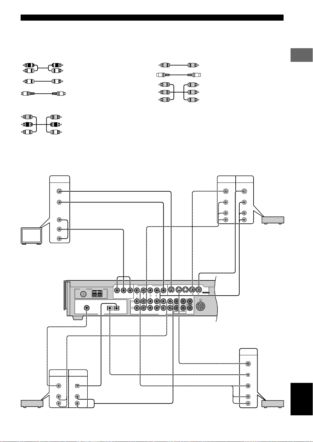
■ The connection example
Use a cable specified for connecting each type of jacks.
(The included video pin cable is used for connecting this unit to a video monitor.)
The connection example shown below is just an example. Connect in accordance with the components you have.
y
• The solid lines indicate the output from this unit and the dotted lines indicate the input to this unit.
For Audio component
Audio pin cable
Coaxial cable
Optical cable
For A/V component
Audio/Video cable
For Video Component
Video pin cable (included)
S Video cable
Component video cable
(U.S.A., Canada, Australia and General
models)
FM ANT
75ΩUNBAL.
GND – AM ANT
PRPBY
L
IN
VIDEO 1 VIDEO 2
VIDEO
VCR
IN IN
IN IN IN
OUT OUT
IN IN IN INOUT OUT
OUT OUT
S VIDEO
MONITOR
MD/CD-R FRONT CENTER
SYSTEM
MONITOR
6CH PREOUT
VIDEO 1 VIDEO 2 VCR
REAR
SUBWOOFER
R
MD/CD-R
COMPONENT VIDEO OUT
OPTICAL
OUT
CONNECTOR
MARK
TO SW-S100
[B]
[A]
COAXIAL
IN
OPTICAL
IN
MD/CD-R VIDEO 1
DIGITAL
ANALOG
S VIDEO
INPUT
VIDEO
AUDIO
L
R
S VIDEO
OUTPUT
VIDEO
AUDIO
L
R
S VIDEO
INPUT
VIDEO
COMPONENT
VIDEO
S VIDEO
OUTPUT
OPTICAL
AUDIO
L
VIDEO
R
INPUT
OPTICAL
AUDIO
L
R
OUTPUT
COAXIAL
AUDIO
L
R
PB/C
B
PR/C
R
Y
S Video cable
Video pin cable (included)
Component video cable
(U.S.A., Canada, Australia and General
models)
Video monitor
S Video cable
Audio/Video
cable
VCR
S Video cable
Audio/Video cable
(U.S.A. model)
Coaxial cable
Audio pin cable
Optical cable
CD recorder or MD recorder
Audio pin cable
S Video cable
Optical cable
Audio/Video cable
TV/digital TV/cable TV
CONNECTIONS
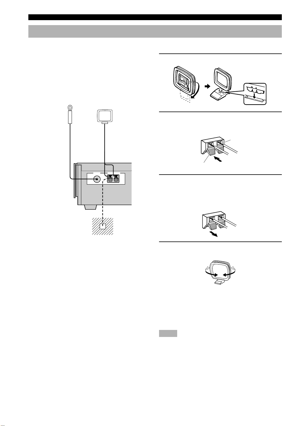
Connecting the antennas
Both AM and FM indoor antennas are included with this
unit. In general, these antennas should provide sufficient
signal strength.
Connect each antenna correctly to the designated
terminals.
■ Connecting indoor FM antenna
Connect the included indoor FM antenna to the FM ANT
terminal.
Indoor FM antenna
(included)
AM loop antenna
(included)
FM ANT GND – AM ANT
75ΩUNBAL.
■ Connecting the AM loop antenna
1 Set up the AM loop antenna, then connect it.
2 Press and hold the tab to insert the AM loop
antenna lead wires into the AM ANT and
GND terminals.
Bare wire
Tab
3 Release the tab. (The tab will return to its
original position when you release your
finger.)
Once connected, pull the wires gently to check that
they are connected securely.
Ground (GND terminal)
For maximum safety and
minimum interference, connect
the antenna GND terminal to a
good earth ground. A good earth
ground is a metal stake driven into
moist earth.
4 Orient the AM loop antenna for the best
reception.
y
• A properly installed outdoor antenna provides clearer reception
than an indoor one. If you experience poor reception quality, an
outdoor antenna may improve the quality. Consult the nearest
authorized YAMAHA dealer or service center about the
outdoor antennas.
Notes
• The AM loop antenna should be placed away from this unit.
• The AM loop antenna should always be connected, even if an
outdoor AM antenna is connected to this unit.
16
CONNECTIONS
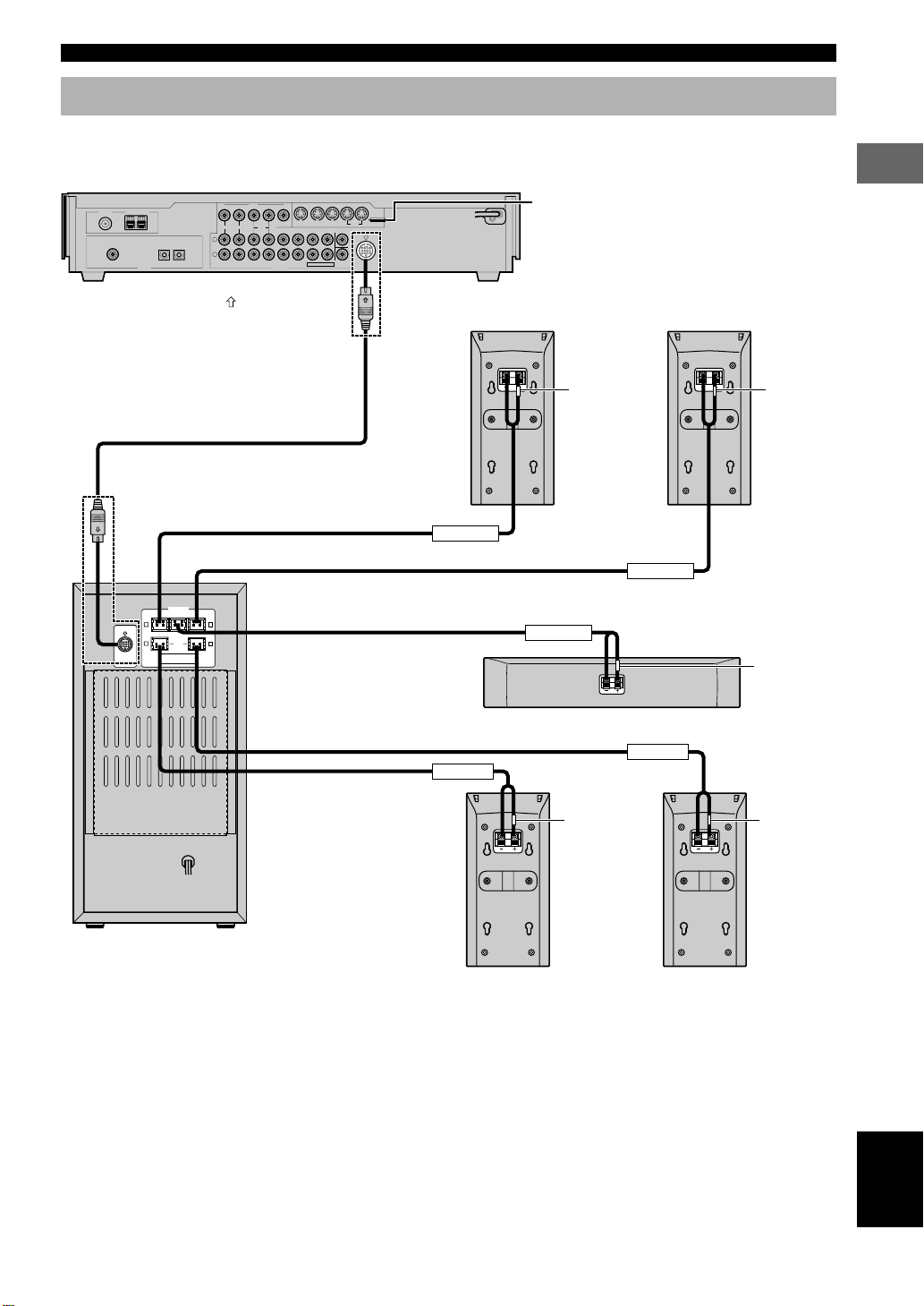
Connecting the speakers
Connect the included speakers to the DVD AUDIO/VIDEO receiver (DVR-S100) using the included speaker cables and
system connector cables as shown below.
DVD Audio/Video receiver (DVR-S100)
FM ANT
GND – AM ANT
75ΩUNBAL.
MD/CD-R
[B]
COAXIAL
IN
[A]
OPTICALINOPTICAL
DIGITAL
MD/CD-RVIDEO 1
OUT
*1 Insert the plug with its
System connector cable
VIDEO
IN
IN IN
VIDEO 1 VIDEO 2
VCR
L
R
IN IN IN INOUT OUT
mark facing up.
OUT OUT
OUT OUT
MONITOR
MONITOR
MD/CD-R FRONT CENTER
ANALOG
IN IN IN
VIDEO 1 VIDEO 2 VCR
REAR
SUBWOOFER
6CH PREOUT
*1
SYSTEM
CONNECTOR
TO SW-S100
S VIDEO
MARK
Front speaker (R)
(NX-S100S)
As this terminal is used for testing at the
factory, do not connect any equipment to this
terminal.
Front speaker (L)
(NX-S100S)
(RED) (WHITE)
PREPARATION
*1
R L
(RED)
MARK
R
(GRAY)
DO NOT CONNECT THIS UNIT TO
SYSTEM
SPEAKERS OTHER THAN NX-S100C
CONNECTOR
AND NX-S100S.
TO DVR-S100
Subwoofer (SW-S100)
SPEAKERS
CENTERFRONT FRONT
(GREEN)
REAR
(SURROUND)
Speaker cable (RED)
Speaker cable (WHITE)
Speaker cable (GREEN)
(WHITE)
L
(BLUE)
Speaker cable (BLUE)
Speaker cable (GRAY)
FRONT R
REAR R
Rear speaker (R)
(NX-S100S)
FRONT L
CENTER
Center speaker (NX-S100C)
REAR L
(GRAY) (BLUE)
Rear speaker (L)
(NX-S100S)
(GREEN)
English
17
CONNECTIONS
(RED)
(RED)
Connector
Color tube
(RED)
Color tube
(BLUE)
The back of the
Subwoofer
(BLUE)
Connector
(BLUE)
y
• The connector of the included speaker cable and the terminal of
the subwoofer are classified by color. Connect the same colors.
• The label of the speaker is attached to each speaker cable.
Connect the speakers in accordance with the labels.
• Connect the color tube of the speaker cable to the plus (+) side
of each speaker. If the polarity of the speaker connections is
incorrect, the sound will be unnatural and lack bass.
• A cover is attached to the end of the speaker cable. Connect the
speakers after removing the cover.
• Make sure that the plugs of the system connector cable and the
connectors of the speaker cables are inserted correctly before
inserting them.
Notes
• Do not let the bare speaker wires touch each other or any metal
part of this unit. This could damage this unit and/or the
speakers.
• Do not insert the plug or connector forcibly. Doing so may
damage the plug, connector or terminal.
• Do not scratch, forcibly bend, or pull the system connector or
speaker cable as this may damage the cable, causing loss of
audio output, and may possibly result in a fire or electric shock.
Take particular care in making sure that the cable is not
squashed by a rack or caster.
• Before disconnecting or connecting the system connector
cable, disconnect the power supply cord of the subwoofer and
DVD audio/video receiver.
■ Using commercially available
speakers and speaker cables
You can use commercially available speaker cables and
speakers except for a subwoofer. If you use them, note the
following.
• Use the speaker whose impedance is 6Ω or higher.
When using the speaker whose impedance is lower than
6Ω, the protection circuit may start working or this unit
may be damaged.
• Use magnetically shielded speakers. If this type of
speakers still creates the interference with the monitor,
place the speakers away from the monitor.
• Use the speaker cable that is as thick as the included
cable. Too thick cables cannot be used.
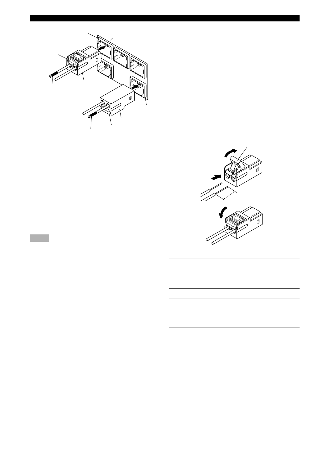
Exchanging the speaker cables
2
Tab
3
1
15 mm
4
1 Remove approximately 15 mm (9/16”) of
insulation from each of the speaker cables.
Twist the exposed wires of the cable together to
prevent short circuits.
2 Open the tab.
3 Pull the inserted bare wire of the speaker
cable from the connector and insert the bare
wire of the commercially available speaker
cable.
4 Return the tab to secure the wire.
18
CONNECTIONS
STANDBY/ON
TV
CH
INPUT
TUNER
MUTE CD–R
VCR
VIDEO 2
VIDEO 1
MD
AV
SLEEP
POWER
TV MODE
POWER
VOL
REC
AUDIO
SUBTITLE
SHIFT
CODE SET
HALL
JAZZ
ROCK
ENTERTAINMENT
DVDCDAMP
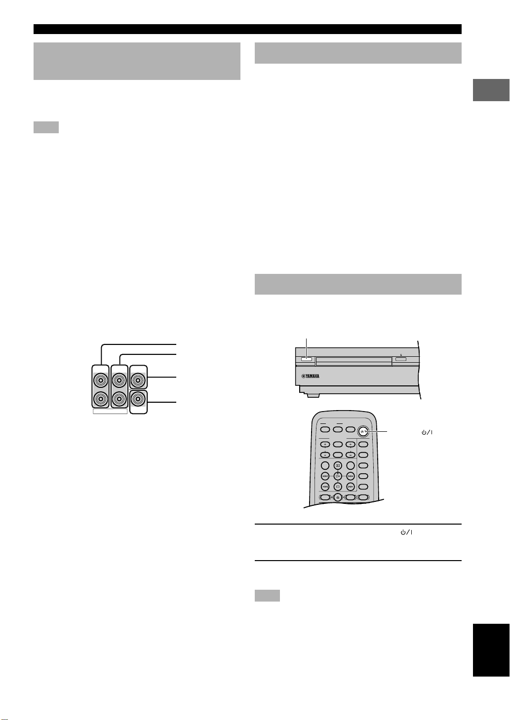
Connecting to an external amplifier
If you want to increase the power output to the speakers,
or want to use another amplifier, connect an external
amplifier to the 6CH PREOUT jacks as follows.
Note
• When you have connected this unit to an external amplifier,
select PRE in “9 SP/PRE OUT” on the SET MENU. (See page
63.)
1 FRONT jacks
Front channel line output jacks.
2 REAR jacks
Rear channel line output jacks.
3 CENTER jack
Center channel line output jack.
4 SUBWOOFER jack
Low bass signals distributed from the front, center and/or
rear channels are directed to this jack if they are assigned
to this jack. (The cut-off frequency of this jack is 90 Hz.)
The LFE (low-frequency effect) signals generated when
Dolby Digital or DTS is decoded are also directed if they
are assigned to this jack.
1
2
FRONT CENTER
REAR
3
Connecting the AC power cord
Plug in this unit to the wall outlet.
■ Memory back-up
The memory back-up circuit prevents the stored data from
being lost when the power cord is disconnected from the
AC outlet, or the power supply is temporarily cut due to
power failure. However, if the unit is turned off for more
than one week, the stored setting will be cleared. If so, set
the setting again.
• Volume level
• Input source
• Speaker output level (center, rear L/R and subwoofer)
• Sleep timer
• Parameter
• Delay time
• Set menu
• Disc direct
• Preset station
Turning on the power
When all connections are complete, turn on the power of
this unit.
STANDBY/ON
PREPARATION
6CH PREOUT
SUBWOOFER
4
y
• The adjustments made in the following settings have an effect
on the signals output from the 6CH PREOUT jacks.
– BASS BOOST settings
– Speaker settings
– DSP programs
POWER ( )
1 Press STANDBY/ON (POWER ( ) on the
remote control) to turn on the power of this
unit.
2 Turn on the video monitor connected to this
unit.
Note
• When you use only some of the included 6 speakers or when
using commercially available speakers, adjust speaker mode
settings soon after turning the power on. See “1 SPEAKER
SET (speaker mode settings)” on page 60 for details.
19
English
ADJUSTING SPEAKER OUTPUT LEVELS
VIDEO 1
SHIFT
CODE SET
1
HALL2JAZZ
SETUP
3
ROCK
ANGLE
4
ENTERTAINMENT
MARKER
5
SPORTS6MONO MOVIE
PLAY MODE
7
MOVIE 1
REPEAT
8
MOVIE 2
A–B
DVDCDAMP
9
/DTS
TOP MENU
LEVEL
MENU
SET MENU
TEST
ON SCREEN
B. BOOST
RETURN
0
SELECT
>
–
10
MATRIX 6.1
GROUP
CANCEL
STEREO
PAGE
MUTE
VOL
ABCDE
ENTER
PRESET
PRESET
CHCH
This section explains how to adjust speaker output levels
using the test tone generator. When this adjustment is
complete, the output level heard at the listening position
should be the same from each speaker. This is important
for best performance of the digital sound field processor,
and the various decoders (Dolby Digital, Dolby Pro
Logic, Dolby Pro Logic II and DTS).
Note
• Since this unit cannot enter the test mode while headphones are
connected to this unit, be sure to unplug the headphones from
the
SILENT jack when using the test tone.
Using the test tone
Use the test tone to balance the output levels of the
speakers.
Note
• The adjustment of each speaker output level should be made at
your listening position using the remote control.
AMP
j, i
TEST
(U.S.A. model)
VOL + / –
1 Press AMP.
2 Press TEST to output the test tone.
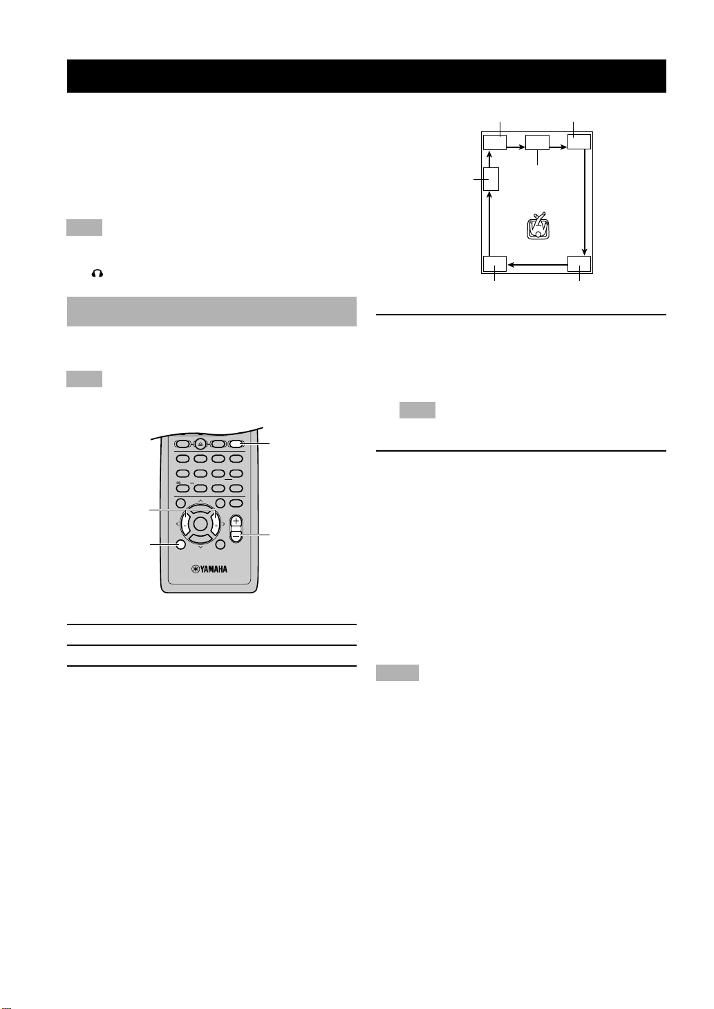
3 Press VOL +/– to adjust the volume of this
unit so you can hear the test tone.
The test tone is heard (in order) from the LEFT
(front left speaker), CENTER (center speaker),
RIGHT (front right speaker), R SUR. (rear right
speaker), L SUR. (rear left speaker), and the
SUBWOOFER (subwoofer). The tone is produced
for about 2 seconds from each speaker.
SUBWOOFER
LEFT
CENTER
RIGHT
L SUR. R SUR.
4 Adjust the level of the effect speakers using
j/i so that it matches the level of the front
speakers.
While adjusting, the test tone is heard from the
selected speaker.
Note
• To adjust the level of the front speakers, use VOL +/– on
the remote control.
5 When adjustment is complete, press TEST to
stop the test tone.
y
• It is not necessary to readjust the speaker levels once they are
set (as long as you do not change the speakers). You can enjoy
listening to or watching the input source at the desired volume
simply by pressing VOL +/– on the remote control.
• If the output level of the effect speakers (center, rear left, and
rear right) cannot be increased enough to match the level of the
front speakers, set “1E F. Level” on SET MENU to –10 dB (see
page 61). This setting decreases the front speaker output level
to about one-third of the normal level. After you have set “1E F.
Level” on the SET MENU to –10 dB, adjust the levels for the
center and rear speakers again.
Notes
• If “1A CENTER” on the SET MENU is set to NON and the
center speaker is not connected, the center channel sound is
automatically output from the front left and right speakers.
• If “1C REAR LR” on the SET MENU is set to NON, the
output level of the rear left and right speakers cannot be
adjusted in step 4. The test tone will be circulated skipping the
rear right and left speakers.
• If “1D BASS” on the SET MENU is set to FRONT, the test
tone will be circulated skipping the subwoofer.
20
BASIC PLAYBACK
TV
CH
INPUT
TUNER
MUTE CD–R
VCR
VIDEO 2
VIDEO 1
MD
AV
SLEEP
POWER
TV MODE
POWER
VOL
REC
AUDIO
SUBTITLE
SHIFT
CODE SET
1
HALL2JAZZ
SETUP
3
ROCK
ANGLE
4
ENTERTAINMENT
MARKER
5
SPORTS6MONO MOVIE
PLAY MODE
7
MOVIE 1
REPEAT
8
MOVIE 2
A–B
DVDCDAMP
9
/DTS
TOP MENU
LEVEL
MENU
SET MENU
TEST
ON SCREEN
B. BOOST
RETURN
0
SELECT
>
–
10
MATRIX 6.1
GROUP
CANCEL
STEREO
PAGE
MUTE
VOL
ABCDE
ENTER
PRESET
CH
PRESET
CH
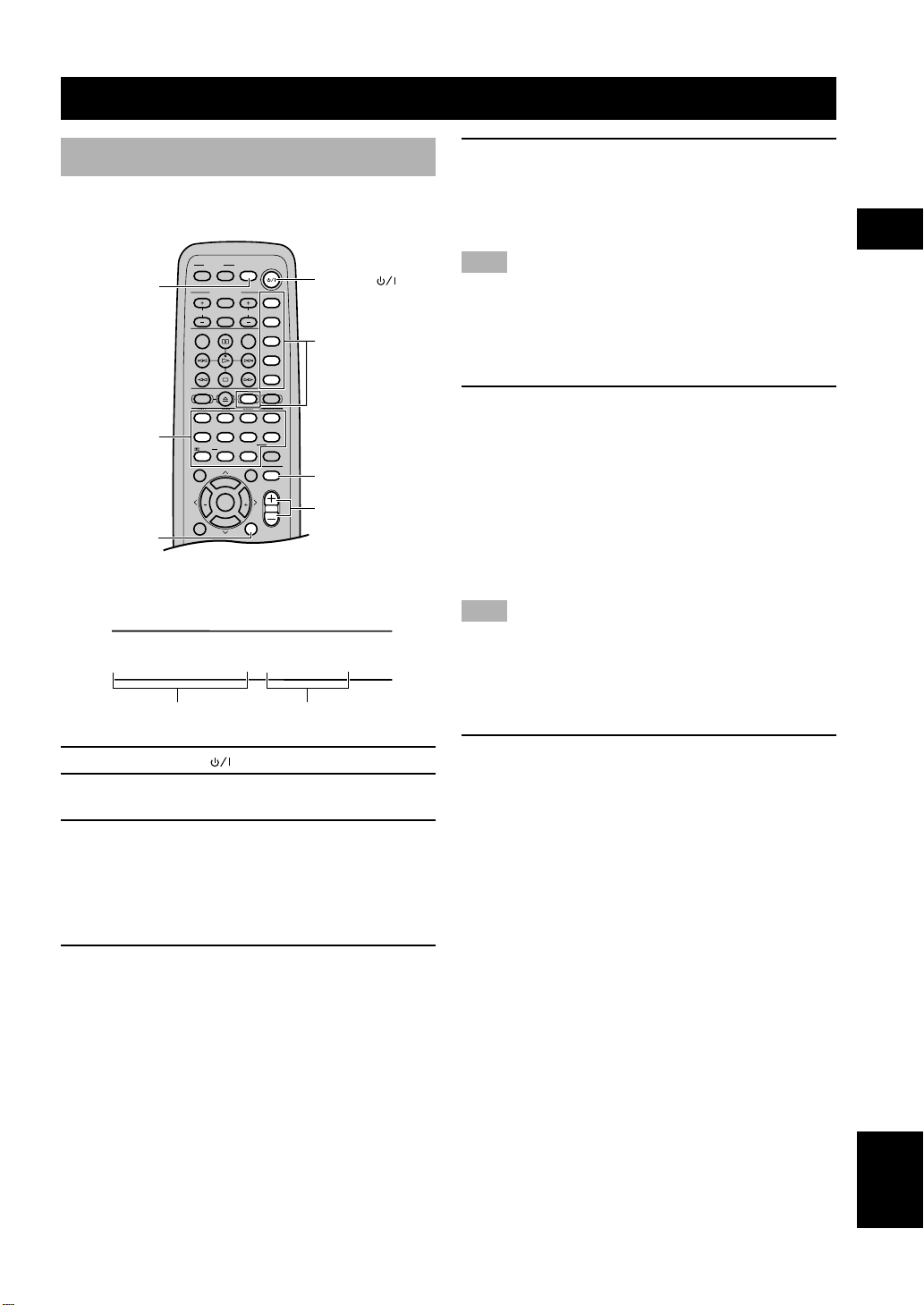
Basic operations
You can play the software loaded on the audio and video
components connected to this unit.
SLEEP
DSP program
buttons
B.BOOST
(U.S.A. model)
POWER ( )
Input selector
buttons
MUTE
VOL + / –
Indication on the front panel display (example):
SP
VIDEO 1
VIDEO 1 AUTO
Selected input source Input mode
5 Adjust the volume to the desired level.
The volume level is displayed digitally.
Example: –70 dB
Control range: VOLUME MUTE (minimum) to
0 dB (maximum)
Note
• If you have connected a recording component to the VCR
OUT, or MD/CD-R OUT jacks, and you notice distortion or
low volume during playback of other components, try turning
the recording component on.
■ Enhancing the bass tones
Press B. BOOST.
•“Bass Boost ON” appears in the display.
• This function enhances the bass tones of the
subwoofer by increasing the level of the low-range
frequencies.
• To cancel B. BOOST mode, press B. BOOST
again.
y
• The B. BOOST mode does not function when the headphones
are connected.
Note
• If a thudding noise is heard from the subwoofer when this
function is turned on, lower the subwoofer level. Otherwise, the
subwoofer may be damaged due to an excessive input level of
low-bass signal.
■ To mute the sound
USING BASIC FUNCTIONS
1 Press POWER ( ) to turn on the power.
2 Turn on the A/V component connected to
this unit.
3 Press INPUT H/G on the front panel
repeatedly (one of the input selector buttons
on the remote control) to select the input
source.
The selected input source name and input mode
appear on the front panel display for a few seconds.
4 Start playback or select a broadcast station
on the source component.
Refer to the operation instructions for the
component.
Press MUTE on the remote control.
To resume the audio output, press MUTE again.
y
• You can also cancel mute by pressing VOL +/–, etc.
• During muting, the “MUTE” indicator flashes on the front
panel display.
English
21
 Loading...