

Page 1

Version 1.5
DIGITAL MIXING ENGINE
Owner’s Manual Supplement
Contents
Introduction . . . . . . . . . . . . . . . . . . . . . . . . . . . . . . . . . . . . . . . . . . . . . . . . . . . . . . . . . . 2
32x32 & 32x16 Matrix Mixer Components . . . . . . . . . . . . . . . . . . . . . . . . . . . . . . . . . 2
Stereo PEQ & GEQ Components . . . . . . . . . . . . . . . . . . . . . . . . . . . . . . . . . . . . . . . . . 4
Parameter Value Copy . . . . . . . . . . . . . . . . . . . . . . . . . . . . . . . . . . . . . . . . . . . . . . . . . . 7
Recall Safe . . . . . . . . . . . . . . . . . . . . . . . . . . . . . . . . . . . . . . . . . . . . . . . . . . . . . . . . . . . . 8
Keyboard & Scrolling Mouse Control . . . . . . . . . . . . . . . . . . . . . . . . . . . . . . . . . . . . . 9
Program Library . . . . . . . . . . . . . . . . . . . . . . . . . . . . . . . . . . . . . . . . . . . . . . . . . . . . . 10
Fade Time . . . . . . . . . . . . . . . . . . . . . . . . . . . . . . . . . . . . . . . . . . . . . . . . . . . . . . . . . . 13
Improved Node Labelling . . . . . . . . . . . . . . . . . . . . . . . . . . . . . . . . . . . . . . . . . . . . . 15
Improved DME Manager Uninstall . . . . . . . . . . . . . . . . . . . . . . . . . . . . . . . . . . . . . 15
Support for Legacy Configurations . . . . . . . . . . . . . . . . . . . . . . . . . . . . . . . . . . . . . . 15
Editing Multiple Parameters Simultaneously . . . . . . . . . . . . . . . . . . . . . . . . . . . . . 16
Improved Parameter Resolution . . . . . . . . . . . . . . . . . . . . . . . . . . . . . . . . . . . . . . . . 16
Support for Windows NT 4.0, 2000 & Me . . . . . . . . . . . . . . . . . . . . . . . . . . . . . . . . 16
Software Version Mismatch Warning . . . . . . . . . . . . . . . . . . . . . . . . . . . . . . . . . . . 16
Page 2
2
Introduction
This document describes the new features of DME32 Version 1.5 and should be used in
conjunction with the original DME32 Owner’s Manual .
32x32 & 32x16 Matrix Mixer Components
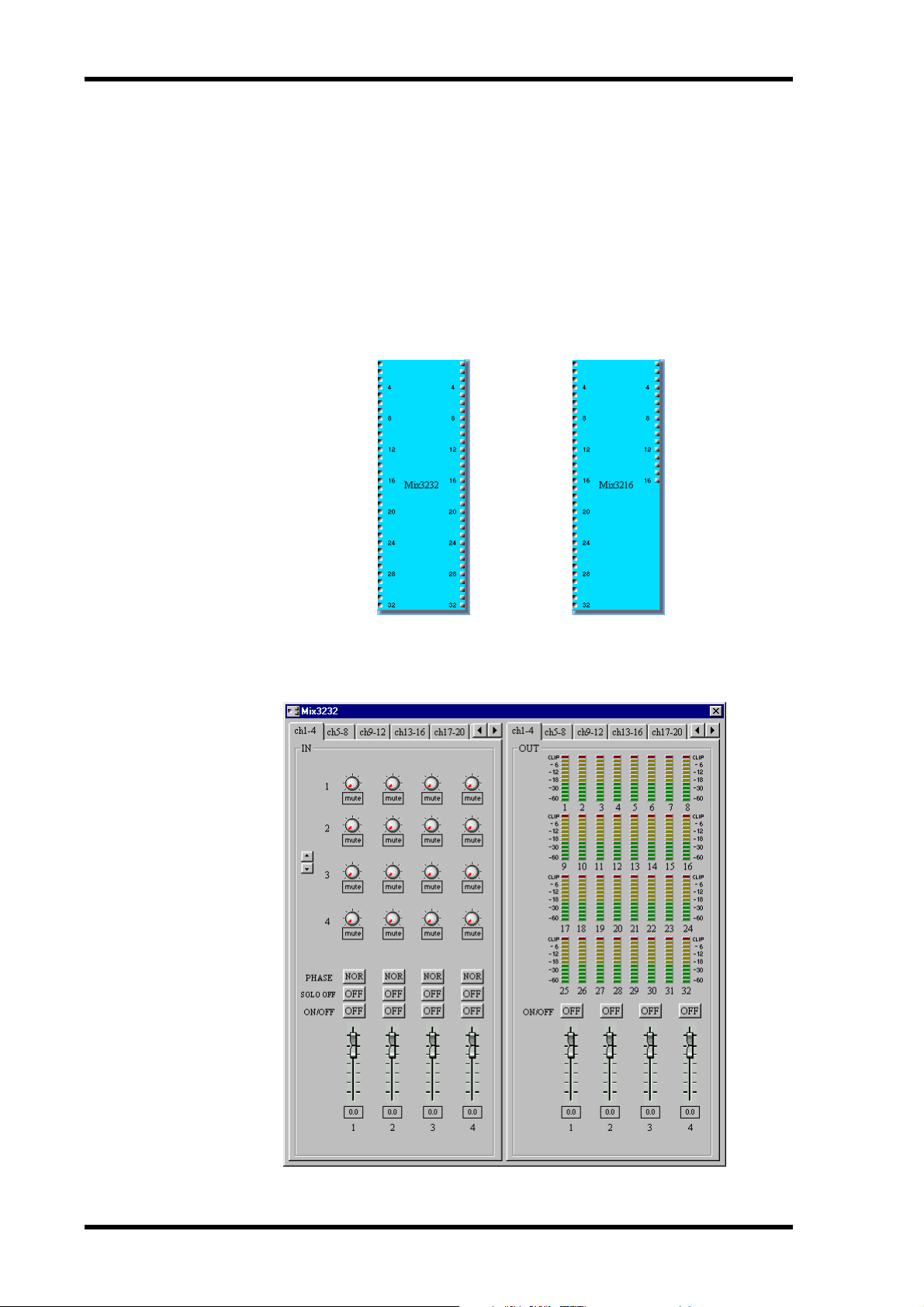
The new 32x32 and 32x16 Matrix Mixer components, shown below, allow the creation
of even larger matrix mixing systems. Note that since these components are processor
intensive, only one of these components can be used with a single DME32 at any one
time.
Each Matrix Mixer control window features an IN section, with various input channel
controls, and an OUT section, with fader and meter for each output channel. The
32x32 Matrix Mixer control window is shown below.
DME32—Owner’s Manual Supplement
Page 3
3
When a channel is soloed, “SOLO OFF” changes to “SOLO ON.” This is convenient on
control windows where the input channels are organized into pages and it’s not possible
to see all SOLO buttons simultaneously.
For components with five or more outputs (i.e., five or more bus level controls
per input channel), the bus level controls in the IN section can be scrolled up or
down by clicking the two arrow buttons shown here.
The parameter ranges for the Matrix Mixers are as follows.
Section Parameter Range Description
Adjusts the level of each input channel signal that is fed to each output channel
IN
OUT
Bus level
PHASE
SOLO
ON/OFF
Fader
ON/OFF
Fader
Mute to +10.0 dB
NOR/REV Inverts each input channel signal
ON/OFF Solos each input channel
ON/OFF Mutes each input channel
Mute to +10.0 dB Adjusts the level of each input channel
ON/OFF Mutes each output channel
Mute to +10.0 dB Adjusts the level of each output channel
For Matrix Mixer components with more than four inputs or outputs, channels are
arranged into pages consisting of four channels. Previously, channels were arranged
into pages consisting of six channels.
DME32—V1.5 Owner’s Manual Supplement
Page 4
4
Stereo PEQ & GEQ Components
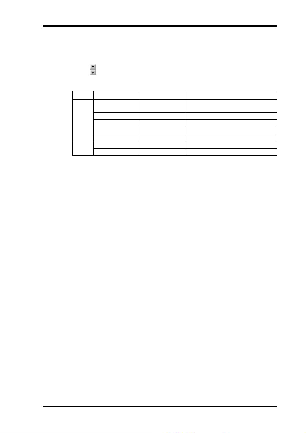
The five new stereo PEQ (parametric equalizer) and three new stereo GEQ (graphic
equalizer) components make it easier to process stereo signals. Essentially these are stereo versions of the existing EQ components.
PEQ
The five stereo PEQ components are shown below.
Each stereo PEQ component features two inputs and two outputs.
Each PEQ control window features an EQ graph and INPUT, EQ BAND, and OUTPUT sections. Since the only difference between all the stereo PEQ components is the
number of bands, only the stereo 4 BAND PEQ control window is shown here.
The parameter ranges for the stereo PEQ components are as follows.
Section Parameter Range Description
ON/OFF
INPUT
EQ BAND
OUTPUT LEVEL
MUTE
1. Top and bottom bands only.
DME32—Owner’s Manual Supplement
LEVEL
PHASE
Q
F
G
ON/OFF
1
Type
ON/OFF Turns the component on and off
Mute to 0.0 dB Adjusts the input signal level
NOR/REV Inverts the input signal
10–0.10 Adjusts the selectivity of each band
20.0 Hz–20.0 kHz Adjusts the frequency of each band
–15 dB to +15 dB Adjusts the gain of each band
ON/OFF Turns each band on and off
Peaking/L.Shelf or
H.Shelf
Mute to 0.0 dB Adjusts the output signal level
ON/OFF Mutes the output
Sets the filter type for the band
Page 5
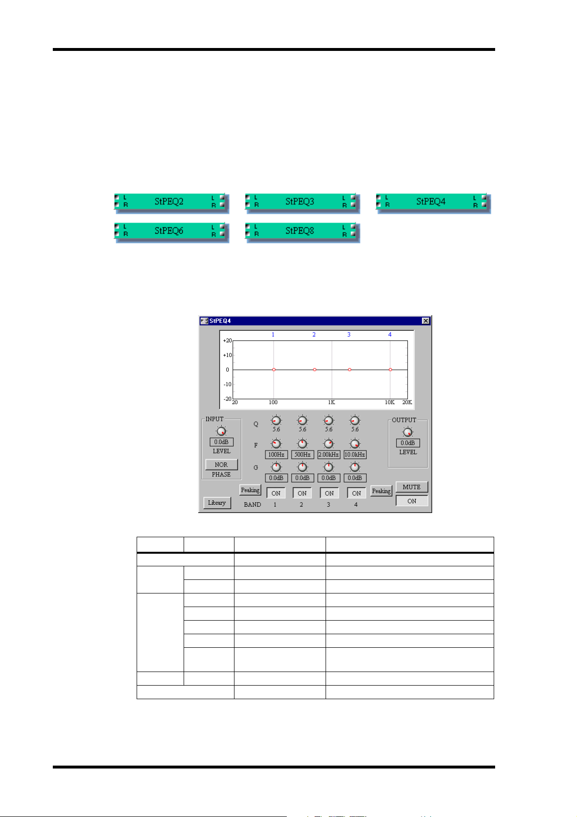
The EQ graph at the top of the window displays the EQ settings graphically, as shown
in the following example. The number of each EQ band appears along the top of the
graph.
5
In addition to using the rotary controls, the frequency (F) and gain (G) parameters for
each band can be set by dragging the small circles on the EQ graph. When the cursor is
placed over a circle, it changes to a hand and the curve can then be dragged to achieve
the required setting.
DME32—V1.5 Owner’s Manual Supplement
Page 6
6
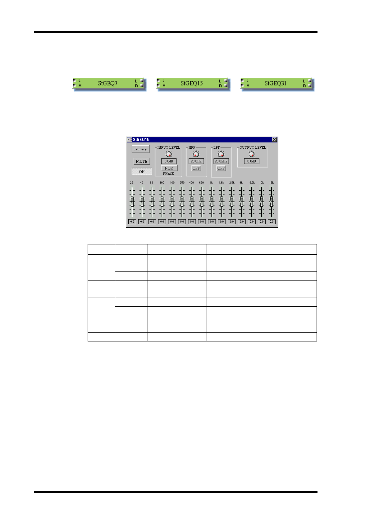
GEQ
The three stereo GEQ components are shown below.
Each GEQ control window consists of five sections: INPUT, HPF, LPF, EQ bands, and
OUTPUT. The center frequency of each band is shown above each slider. Since the only
difference between all the GEQ components is the number of bands, only the stereo 15
BAND GEQ control window is shown here.
The parameter ranges for the stereo GEQ components are as follows.
Section Parameter Range Description
ON/OFF
INPUT
HPF
LPF
EQ band Gain
OUTPUT LEVEL
MUTE
LEVEL
PHASE
Frequency
ON
Frequency
ON
ON/OFF Turns the component on and off
Mute to 0.0 dB Adjusts the input signal level
NOR/REV Inverts the input signal
20.0 Hz–20.0 kHz Adjusts the HPF cutoff frequency
ON/OFF Turns the HPF on or off
20.0 Hz–20.0 kHz Adjusts the LPF cutoff frequency
ON/OFF Turns the LPF on or off
–15 dB to +15 dB Adjusts the gain of each band
Mute to 0.0 dB Adjusts the output signal level
ON/OFF Mutes the output
DME32—Owner’s Manual Supplement
Page 7

Parameter Value Copy
Parameter values can now be copied and pasted among parameters of the same type on
a component.
1
Select the control whose value you want to copy by clicking it.
The selected control is highlighted by a green box.
Copy will not work if several controls are selected.
2
While holding down the shift key, right-click the control.
The following menu appears.
7
3
Choose Copy.
4
Select the control to which you want to paste by clicking it.
Parameter values can only be pasted to parameters of the same type.
5
While holding down the shift key, right-click the control.
The following menu appears.
6
Choose Paste.
The parameter value is pasted to the selected control.
Once a parameter value has been copied, it can be pasted many times.
DME32—V1.5 Owner’s Manual Supplement
Page 8

8
Recall Safe
With the new Recall Safe function, parameter settings can be left unchanged when
scenes are recalled. Recall safe can be applied at the configuration, component, or
parameter level.
Recall safe applies to rotary controls, sliders, and buttons but not combo boxes (e.g., the
SLOPE & TYPE boxes of the crossover components).
Recall Safe for Individual Parameters
Select the control of the parameter that you want to make safe.
1
The selected control is highlighted by a green box.
2
While holding down the shift key, right-click the control.
The following menu appears.
3
Choose Recall Safe.
The selected control is made safe. Next time this menu is accessed for this parameter, a
check mark is displayed next to “Recall Safe”, indicating that the parameter is safe.
Controls, sliders, buttons, etc., appear red when they are set as safe.
Safe parameters are not changed when scenes are recalled.
4
To turn off recall safe, access the previous menu and choose Recall Safe again.
The recall safe setting of individual parameters cannot be changed in Run mode.
Recall Safe for Individual Components
1
Select the component that you want to make safe.
The selected component is highlighted by a red box.
2
While holding down the shift key, right-click the component.
The following menu appears.
DME32—Owner’s Manual Supplement
Page 9

Choose Recall Safe.
3
The selected component is made safe. Next time this menu is accessed for this component, a check mark is displayed next to “Recall Safe”, indicating that the component is
safe.
Safe components are not changed when scenes are recalled.
4
To turn off recall safe, access the previous menu and choose Recall Safe again.
The recall safe setting of individual components cannot be changed in Run mode.
Recall Safe for Configurations
1
Click the Recall Safe icon on the Tool Bar.
Alternatively, choose Recall Safe All Components from the Tool menu.
A confirmation dialog box appears.
9
2
Click Yes to enable recall safe for all components.
All components are made safe. Next time the Recall Safe All Components menu is
accessed, a check mark is displayed next to “Recall Safe All Components”, indicating
that all components are safe.
Safe components are not changed when scenes are recalled.
3
To turn off recall safe, click the Recall Safe icon on the Tool Bar.
Alternatively, choose Recall Safe All Components from the Tool menu.
The recall safe setting of all components cannot be changed in Run mode.
Keyboard & Scrolling Mouse Control
Rotary and slider controls can now be adjusted by using the up/down cursor keys and
Page Up/Page Down keys on your computer keyboard, or the scroll wheel on a scrolling
mouse. In addition, gain, level, and frequency values can be entered from the keyboard.
1
Select the control that you want to adjust.
The selected control is highlighted by a green box.
2
Use the Up/Down cursor keys, Page Up/Page Down keys, or the scroll wheel
on a scrolling mouse to increment or decrement the value of the selected
parameter.
3
To enter a gain, level, or frequency value from your keyboard, select the
parameter value by double-clicking it, enter the new value by using the
numeric keys, and then press Enter.
DME32—V1.5 Owner’s Manual Supplement
Page 10

10
Program Library
With the new program library, up to 100 user programs can be stored for each EQ,
dynamics, and effects component. Programs are stored to disk in the “Lib” folder of the
DME program folder, from which they can be recalled in other configurations.
EQ, dynamics, and effects components feature a Library button, like the one shown
below, that is used to access the Library functions. The procedure for storing, recalling,
and deleting programs is the same whether it be an EQ, dynamics, or effects program.
The Reverb Hall effects component is used here to explain operation. Programs can be
stored and recalled in Run mode.
Storing Programs
1
Open an EQ, dynamics, or effects control window.
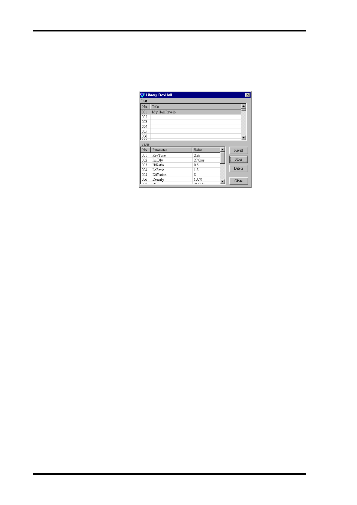
2
Click the Library button.
The Library window opens, as shown below.
3
Select a program location from 001 through 100.
4
Click the Store button.
The Title Edit window appears, as shown below.
5
Enter a title for the program.
Titles may contain up to 24 characters.
DME32—Owner’s Manual Supplement
Page 11

Click OK.
6
A confirmation dialog box appears.
7
Click Yes to store the program, or click No to cancel.
The program is stored and its title appears in the program list, as shown below.
11
8
Click Close when you’ve finished.
Recalling Programs
1
Open an EQ, dynamics, or effects control window.
2
Click the Library button.
The Library window opens, as shown below.
3
Select the program that you want to recall.
Click the Recall button.
4
A confirmation dialog box appears.
5
Click Yes to recall the program, or click No to cancel.
The program is recalled.
6
Click Close when you’ve finished with the library.
DME32—V1.5 Owner’s Manual Supplement
Page 12
12
Deleting Programs
1 Open an EQ, dynamics, or effects control window.
2 Click the Library button.
The Library window opens, as shown below.
3 Select the program that you want to delete.
4 Click the Delete button.
A confirmation dialog box appears.
5 Click Yes to delete the program, or click No to cancel.
The program is deleted.
6 Click Close when you’ve finished.
DME32—Owner’s Manual Supplement
Page 13

Fade Time
Previously, level faders jumped to their new positions the instant a scene was recalled.
With the new Fade Time function, you can now specify a fade time of up to 60 seconds—ideal for fade ins, fade outs, and crossfades. A Fade Time can be applied to all
level faders or to individual Fader component faders.
In order to use this function, the Fade Time setting must be stored in a scene and the
configuration recompiled and transferred to the DME32. When that scene is recalled,
the specified fade time comes into effect.
Specifying a Fade Time
Fade Time settings can be made only in Edit mode.
Note: If you switch from Run mode to Edit mode and edit the Fade Time settings, you
must recompile the configuration and transfer it back to the DME32 before you can select
Run mode again.
1 Choose Fade Time from the Tool menu.
The Offline Edit window and the Fade Time dialog box appear, as shown below.
13
Remember that Fade Time settings made here apply to the current scene of the current
configuration, so if you want to edit the Fade Time settings of an existing scene, recall
that scene first from the Offline Edit window. See the DME32 Owner’s Manual for more
information.
2 Set the Fade Time as required.
Setting resolution is in 0.1 second steps for the 0 through 10 second range and 1 second
steps for the 10 through 60 second range.
3 Set the On/Off switch to on.
The On/Off button toggles the Fade Time function on and off for each scene.
4 Set the All levels/Selected faders option as required.
When All levels is selected, the Fade Time function affects all level faders, including, for
example, the level faders on the Automatic Mixers and the Matrix Mixers. When it’s set
to Selected faders, however, only those Fader component faders whose Fade button is
DME32—V1.5 Owner’s Manual Supplement
Page 14

14
turned on are affected. The Fader component Fade buttons, which are new to Version
1.5, are shown below on the 8-channel Fader component’s control window.
5 Click Apply to apply your settings and leave the Fade Time window open, click
OK to apply your settings and close the window, or click Cancel to leave the
settings unchanged and close the window.
Using the Apply button instead of the OK button is convenient when you want to set
the Fade time for several scenes without having to keep opening and closing the Fade
Time dialog box.
6 Store the Fade Time setting in a scene by storing the scene.
7 Compile and transfer the configuration to the DME32.
See the DME32 Owner’s Manual for information on compiling and transferring configurations to the DME32.
Fade Time Notes
If you edit a parameter using DME Manager, the DME32 front panel, MIDI, or the GPI
interface while a fade is in progress, the fade will not be applied to that parameter.
When the Fade Time is set to Selected faders, if you deselect a fader while a fade is in
progress, the fade will not be applied to that fader.
Parameters to which the fade does not apply, such as frequency parameters, can be
edited as normal while a fade is in progress.
If a configuration is loaded or transferred while a fade is in progress, the fade is canceled
and the faders move to their new values.
DME32—Owner’s Manual Supplement
Page 15

Improved Node Labelling
For components with many inputs and outputs, certain nodes are now
labeled in order to help distinguish them more easily. This applies to
components with five or more input or output nodes, with every fourth
node being labelled (e.g., 4, 8, 12, and so on). The new node numbers
can be seen here on the new 32x32 Matrix Mixer component.
In addition, “L” and “R” labels have been added to
effects and dynamics components with two inputs or two outputs,
as shown here.
15
Improved DME Manager Uninstall
Previously, files left in the DME folder after DME Manager was uninstalled used to
cause problems when a newer version of DME Manager was installed. This issue has
now been resolved.
Support for Legacy Configurations
To support the new features of Version 1.5, the DME file format has been updated. The
first time a configuration created using an earlier version of DME Manager is opened
or transferred from the DME32, it’s automatically converted to a Version 1.5 compatible configuration.
Note: When a Version 1.5 configuration is used with an earlier version of DME Manager,
normal performance cannot be guaranteed and operation may be unreliable.
DME32—V1.5 Owner’s Manual Supplement
Page 16

16
Editing Multiple Parameters Simultaneously
Previously, using DME Manager, only one parameter could be edited at a time. In Version 1.5, up to eight parameters of the same type can be selected and edited simultaneously.
1 While holding down the Shift key, click the parameters that you want to edit.
The selected controls are highlighted by green boxes.
2 Release the Shift key when you’ve completed your selection.
3 Edit one of the selected parameters in the normal way.
All the selected parameters are edited.
Permanent links can be created between parameters by using the Link function.
the DME32 Owner’s Manual for more information.
Improved Parameter Resolution
The resolution of frequency, gain, and level parameters has been improved, offering
increased setting precision. PEQ and GEQ gain values, for examples, can now be set in
0.1 dB steps.
Support for Windows NT 4.0, 2000 & Me
In addition to the operating systems stated in the DME32 Owner’s Manual, DME Man-
ager V1.5 supports Windows NT 4.0, 2000, and Me. With Windows NT, USB cannot be
used because it’s not supported by that particular operating system.
Software Version Mismatch Warning
When DME Manager is started, it establishes communication with the DME32 and
checks to see if its version number matches that of the DME32 system software. If it
doesn’t match, a warning message appears. You can still use the system even if this message appears, although, normal performance cannot be guaranteed and operation may
be unreliable. For correct operation, the DME32 system software should be upgraded
to match that of DME Manager.
If the DME32 system software is a later version than DME Manager, no communications can be established during startup and the message “DME32 not found!” appears.
See
DME32—Owner’s Manual Supplement
Page 17

documentation manual, user maintenance, brochure, user reference, pdf manual
This file has been downloaded from:
User Manual and User Guide for many equipments like mobile phones, photo cameras, monther board, monitors, software, tv, dvd, and othes..
Manual users, user manuals, user guide manual, owners manual, instruction manual, manual owner, manual owner's, manual guide,
manual operation, operating manual, user's manual, operating instructions, manual operators, manual operator, manual product,
 Loading...