

Page 1
Yamaha DM2000 Update V1.1
This document explains the new and revised functions for DM2000 Update 1.1.
Scene Memory & Input/Output Patch Linking
Input Patch and Output Patch library memories can
be linked to Scene memories so that when a Scene is
recalled, the input and output patches are recalled as
well.
The PATCH LINK INPUT and OUTPUT parameters can be found on the Scene Memory page shown
below, which is located by pressing the SCENE
MEMORY [DISPLAY] button.
5.1 ON
3-1 ON
5.1 OFF
3-1 OFF
Use the cursor buttons to select the PATCH LINK
INPUT and OUTPUT parameters, use the Parameter wheel to select Input Patch and Output Patch
library memories, and press the [ENTER] button to
set. A dash (–) means that no patch memory is
selected.
When you store a Scene, the last recalled or stored
Input Patch and Output Patch library memories are
automatically linked to that Scene.
If the specified Input or Output Patch library memory contains no data, only the Scene is recalled, the
input and output patching will remain the same.
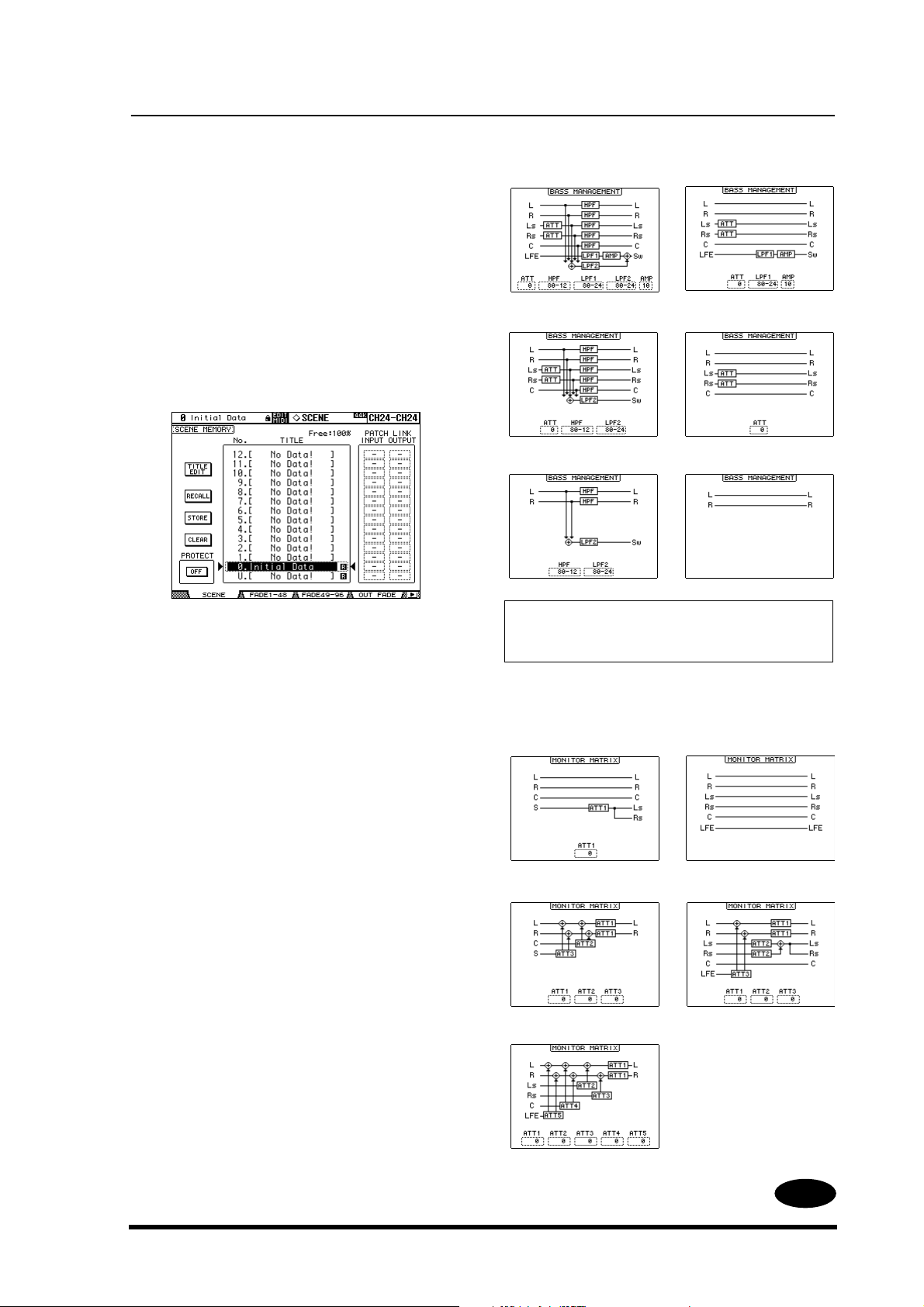
Bass Management for 3-1 & ST
Monitor Matrixes
Bass Management can now be used with the 3-1 and
Stereo Out monitor matrixes. Previously, Bass Management could be used only with the 5.1 monitor
matrix. The Bass Management function can be
found on the Surround Monitor Setup page, which
can be located by using the MONITOR [DISPLAY]
button when either the 3-1 or 5.1 Surround mode is
selected.
The following screen shots show the Bass Management configurations for the 5.1, 3-1, and Stereo
monitor matrixes, with Bass Management turned on
and off.
ST ON
Note: When using the 3-1 monitor matrix, even with
film sources, use Bass Management presets 1 and 2
(presets 3 and 4 may not provide correct monitoring).
In addition, the Monitor Matrix configurations have
changed as follows. (The 5.1 to 5.1 matrix is
unchanged.)
3-1 to 3-1
3-1 to ST
5.1 to ST
ST OFF
5.1 to 5.1
5.1 to 3-1
E
1
Page 2
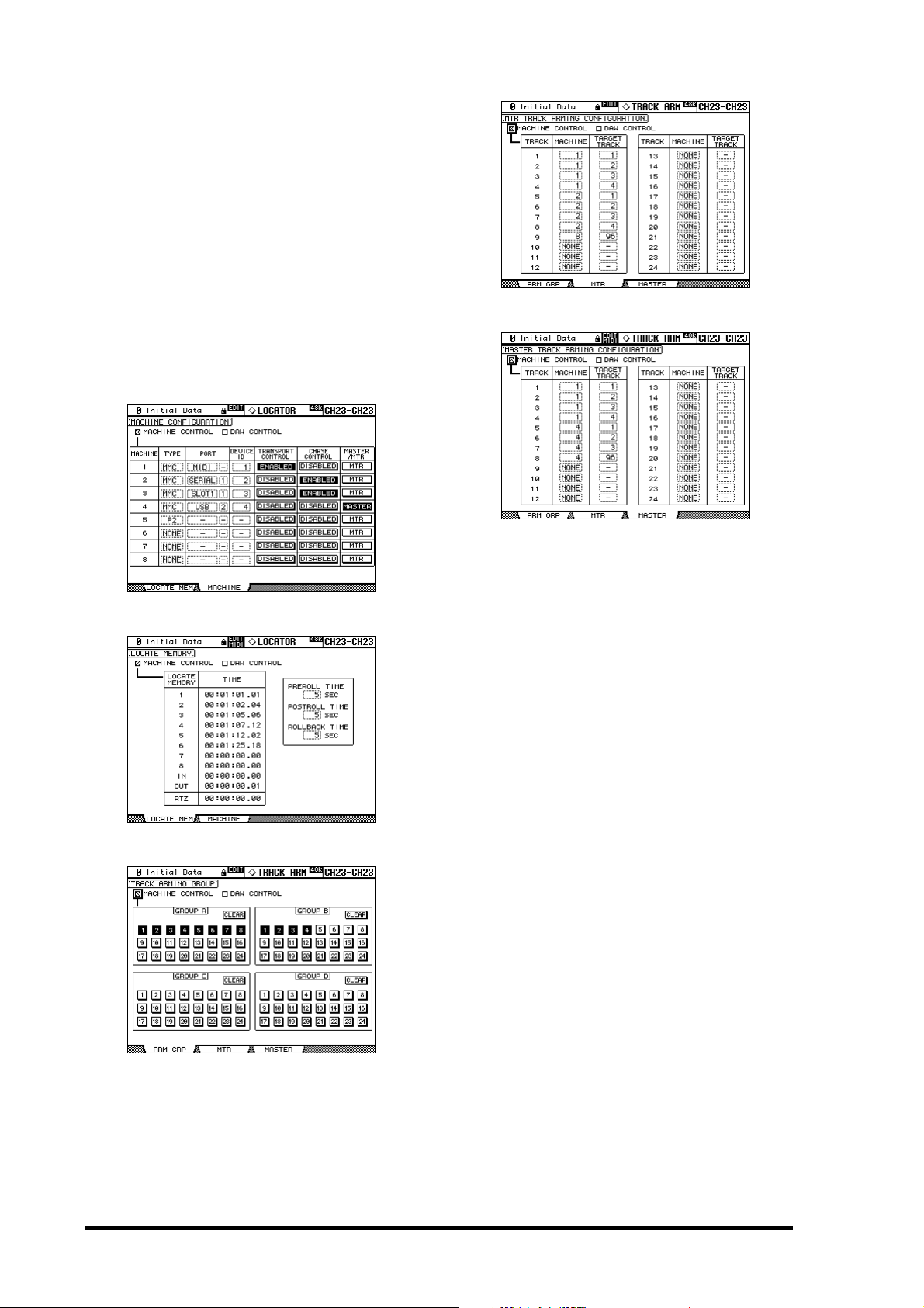
DAW Control Regardless of Layer Selection
Previously, the transport controls, locator, track
arming functions, and shuttle and scrub could be
used to control an external DAW only when a
Remote Layer was selected. With the new DAW
CONTROL option, a DAW can be controlled
regardless of which Layer is currently selected.
The new MACHINE CONTROL and DAW CONTROL options have been added to the following five
pages: Machine Configuration and Locate Memory,
which are selected by using the LOCATOR [DISPLAY] button, and Track Arming Group, MTR
Tr ack Arming Configuration, and Master Track
Arming Configuration, which are selected by using
the TRACK ARMING [DISPLAY] button.
When the MACHINE CONTROL option is on,
external MMC/P2 machines can be controlled,
except when a DAW Remote layer is selected, in
which case the DAW is controlled. When the DAW
CONTROL option is on, the DAW can be controlled
regardless of which Layer is currently selected.
2
Page 3

1
2
2
3
3
Dimmer & Talkback Control via the CONTROL Port
The Control Room and Surround Monitor Dimmers, and the Talkback function can now be controlled remotely via the CONTROL port.
Each time the GPI0 input (pin 22) goes Low
(ground), Talkback is turned on or off. Each time the
GPI1 input (pin 10) goes Low (ground), the Dimmer is turned on or off.
Solo to Studio Out
With the new Solo Bus to Studio Out preference on
the Preferences 1 page, which can be selected by
using the DISPLAY ACCESS [SETUP] button,
soloed channels can now be monitored through the
STUDIO MONITOR OUT.
User Defined Keys
The following items have been added to the list of
functions that can be assigned to the USER
DEFINED KEYS.
# Function Display
161 Surr Lib. Recall +1 Surr Lib+1 RCL
162 Surr Lib. Recall –1 Surr Lib–1 RCL
163 Surr Lib. Recall No. XX Surr LibXX RCL
Functions are assigned to the USER DEFINED KEYS
on the USER DEFINED KEY ASSIGN page, which is
selected by using the USER DEFINED KEYS [DISPLAY] button.
In addition, the following initial assignments of
USER DEFINED KEYS Bank A have changed.
# Bank A # Bank A
1
SOLO ON —>
No Assign —>
No Assign —>
Surr Lib 0 RCL
Surr Lib –1 RCL
Surr Lib +1 RCL
When the Solo Bus to Studio Out preference is on,
and all the STUDIO signal source buttons in the
MONITOR section are off (i.e., [CONTROL
ROOM], [STEREO], [AUX 11], and [AUX 12]), the
Solo signal is output by the STUDIO MONITOR
OUT when channels are soloed.
3
Page 4

M.D.G., PA·DMI Division, Yamaha Cor poration
© 2002 Yamaha Corporation
Page 5

documentation manual, user maintenance, brochure, user reference, pdf manual
This file has been downloaded from:
User Manual and User Guide for many equipments like mobile phones, photo cameras, monther board, monitors, software, tv, dvd, and othes..
Manual users, user manuals, user guide manual, owners manual, instruction manual, manual owner, manual owner's, manual guide,
manual operation, operating manual, user's manual, operating instructions, manual operators, manual operator, manual product,
 Loading...