

UCA
RX-E100 / CDX-E100
Natural Sound Stereo Receiver/Natural Sound Compact Disc Player
Récepteur Stéréo/Lecteur Compact Disque
RL
OWNER’S MANUAL
MODE D’EMPLOI
SAFETY INSTRUCTIONS
6A A unit and cart combination should be
CAUTION
RISK OF ELECTRIC SHOCK
DO␣ NOT OPEN
CAUTION: TO REDUCE THE RISK OF
ELECTRIC SHOCK, DO NOT REMOVE
COVER (OR BACK). NO USER-SERVICEABLE
PARTS INSIDE. REFER SERVICING TO
QUALIFIED SERVICE PERSONNEL.
• Explanation of Graphical Symbols
The lightning flash with arrowhead symbol,
within an equilateral triangle, is intended to
alert you to the presence of uninsulated
“dangerous voltage” within the product’s
enclosure that may be of sufficient
magnitude to constitute a risk of electric
shock to persons.
The exclamation point within an equilateral
triangle is intended to alert you to the
presence of important operating and
maintenance (servicing) instructions in the
literature accompanying the appliance.
WARNING
TO REDUCE THE RISK OF FIRE OR ELECTRIC
SHOCK, DO NOT EXPOSE THIS UNIT TO RAIN
OR MOISTURE.
IMPORTANT!
Please record the serial number of this unit in the space
below.
Model:
Serial No.:
The serial number is located on the rear of the unit.
Retain this Owner’s Manual in a safe place for future
reference.
1 Read Instructions – All the safety and operating
instructions should be read before the unit is operated.
2 Retain Instructions – The safety and operating
instructions should be retained for future reference.
3 Heed Warnings – All warnings on the unit and in the
operating instructions should be adhered to.
4 Follow Instructions – All operating and other
instructions should be followed.
5 Water and Moisture – The unit should not be used near
water – for example, near a bathtub, washbowl, kitchen
sink, laundry tub, in a wet basement, or near a
swimming pool, etc.
6 Carts and Stands – The unit should be used only with a
cart or stand that is recommended by the manufacturer.
moved with care. Quick stops,
excessive force, and uneven surfaces
may cause the unit and cart combination
to overturn.
7 Wall or Ceiling Mounting – The unit should be mounted
to a wall or ceiling only as recommended by the
manufacturer.
8 Ventilation – The unit should be situated so that its
location or position does not interfere with its proper
ventilation. For example, the unit should not be situated
on a bed, sofa, rug, or similar surface, that may block
the ventilation openings; or placed in a built-in
installation, such as a bookcase or cabinet that may
impede the flow of air through the ventilation openings.
9 Heat – The unit should be situated away from heat
sources such as radiators, stoves, or other appliances
that produce heat.
10 Power Sources – The unit should be connected to a
power supply only of the type described in the operating
instructions or as marked on the unit.
11 Power-Cord Protection – Power-supply cords should be
routed so that they are not likely to be walked on or
pinched by items placed upon or against them, paying
particular attention to cords at plugs, convenience
receptacles, and the point where they exit from the unit.
12 Cleaning – The unit should be cleaned only as
recommended by the manufacturer.
13 Nonuse Periods – The power cord of the unit should be
unplugged from the outlet when left unused for a long
period of time.
14 Object and Liquid Entry – Care should be taken so that
objects do not fall into and liquids are not spilled into
the inside of the unit.
15 Damage Requiring Service – The unit should be
serviced by qualified service personnel when:
A. The power-supply cord or the plug has been
B. Objects have fallen, or liquid has been spilled into
C. The unit has been exposed to rain; or
D. The unit does not appear to operate normally or
E. The unit has been dropped, or the cabinet damaged.
16 Servicing – The user should not attempt to service the
unit beyond those means described in the operating
instructions. All other servicing should be referred to
qualified service personnel.
17 Power Lines – An outdoor antenna should be located
away from power lines.
18 Grounding or Polarization – Precautions should be
taken so that the grounding or polarization is not
defeated.
damaged; or
the unit; or
exhibits a marked change in performance; or
2
19 For U.S. customers only:
Outdoor Antenna Grounding – If an outside antenna is
connected to this unit, be sure the antenna system is
grounded so as to provide some protection against
voltage surges and built-up static charges. article 810 of
the National Electrical Code, ANSI/NFPA 70, provides
information with regard to proper grounding of the mast
and supporting structure, grounding of the lead-in wire
to an antenna discharge unit, connection to grounding
electrodes, and requirements for the grounding
electrode.
Note to CATV system installer:
This reminder is provided to call the CATV system
installer’s attention to Article 820-40 of the NEC that
provides guidelines for proper grounding and, in
particular, specifies that the cable ground shall be
connected to the grounding systerm of the building, as
close to the point of cable entry as practical.
FCC INFORMATION (for US customers only)
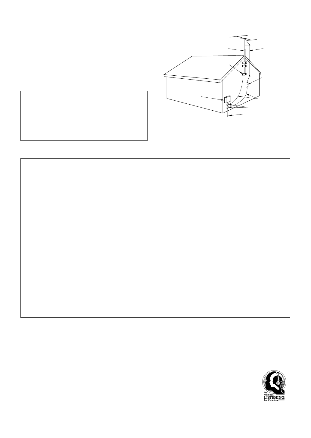
EXAMPLE OF ANTENNA GROUNDING
MAST
GROUND
CLAMP
ELECTRIC
SERVICE
EQUIPMENT
NEC
– NATIONAL ELECTRICAL CODE
ANTENNA
LEAD IN
WIRE
ANTENNA
DISCHARGE UNIT
(NEC SECTION 810–20)
GROUNDING CONDUCTORS
(NEC SECTION 810–21)
GROUND CLAMPS
POWER SERVICE GROUNDING
ELECTRODE SYSTEM
(NEC ART 250. PART H)
1. IMPORTANT NOTICE: DO NOT MODIFY THIS
UNIT!
This product, when installed as indicated in the
instructions contained in this manual, meets FCC
requirements. Modifications not expressly approved by
Yamaha may void your authority, granted by the FCC, to
use the product.
2. IMPORTANT: When connecting this product to
accessories and/or another product use only high quality
shielded cables. Cable/s supplied with this product
MUST be used. Follow all installation instructions.
Failure to follow instructions could void your FCC
authorization to use this product in the USA.
3. NOTE: This product has been tested and found to comply
with the requirements listed in FCC Regulations, Part 15
for Class “B” digital devices. Compliance with these
requirements provides a reasonable level of assurance
that your use of this product in a residential environment
will not result in harmful interference with other
electronic devices.
This equipment generates/uses radio frequencies and, if
not installed and used according to the instructions found
in the users manual, may cause interference harmful to
the operation of other electronic devices.
We Want You Listening For A Lifetime
Compliance with FCC regulations does not guarantee that
interference will not occur in all installations. If this product
is found to be the source of interference, which can be
determined by turning the unit “OFF” and “ON”, please try
to eliminate the problem by using one of the following
measures:
Relocate either this product or the device that is being
affected by the interference.
Utilize power outlets that are on different branch (circuit
breaker or fuse) circuits or install AC line filter/s.
In the case of radio or TV interference, relocate/reorient the
antenna. If the antenna lead-in is 300 ohm ribbon lead,
change the lead-in to coaxial type cable.
If these corrective measures do not produce satisfactory
results, please contact the local retailer authorized to
distribute this type of product. If you can not locate the
appropriate retailer, please contact Yamaha Electronics
Corp., U.S.A. 6660 Orangethorpe Ave, Buena Park, CA
90620.
The above statements apply ONLY to those products
distributed by Yamaha Corporation of America or its
subsidiaries.
YAMAHA and the Electronic Industries Association’s Consumer Electronics Group want you to get the most out of your
equipment by playing it at a safe level. One that lets the sound come through loud and clear without annoying blaring or
distortion – and, most importantly, without affecting your sensitive hearing. Since hearing damage from loud sounds is
often undetectable until it is too late, YAMAHA and the Electronic Industries Association’s Consumer
Electronics Group recommend you to avoid prolonged exposure from excessive volume levels.
3
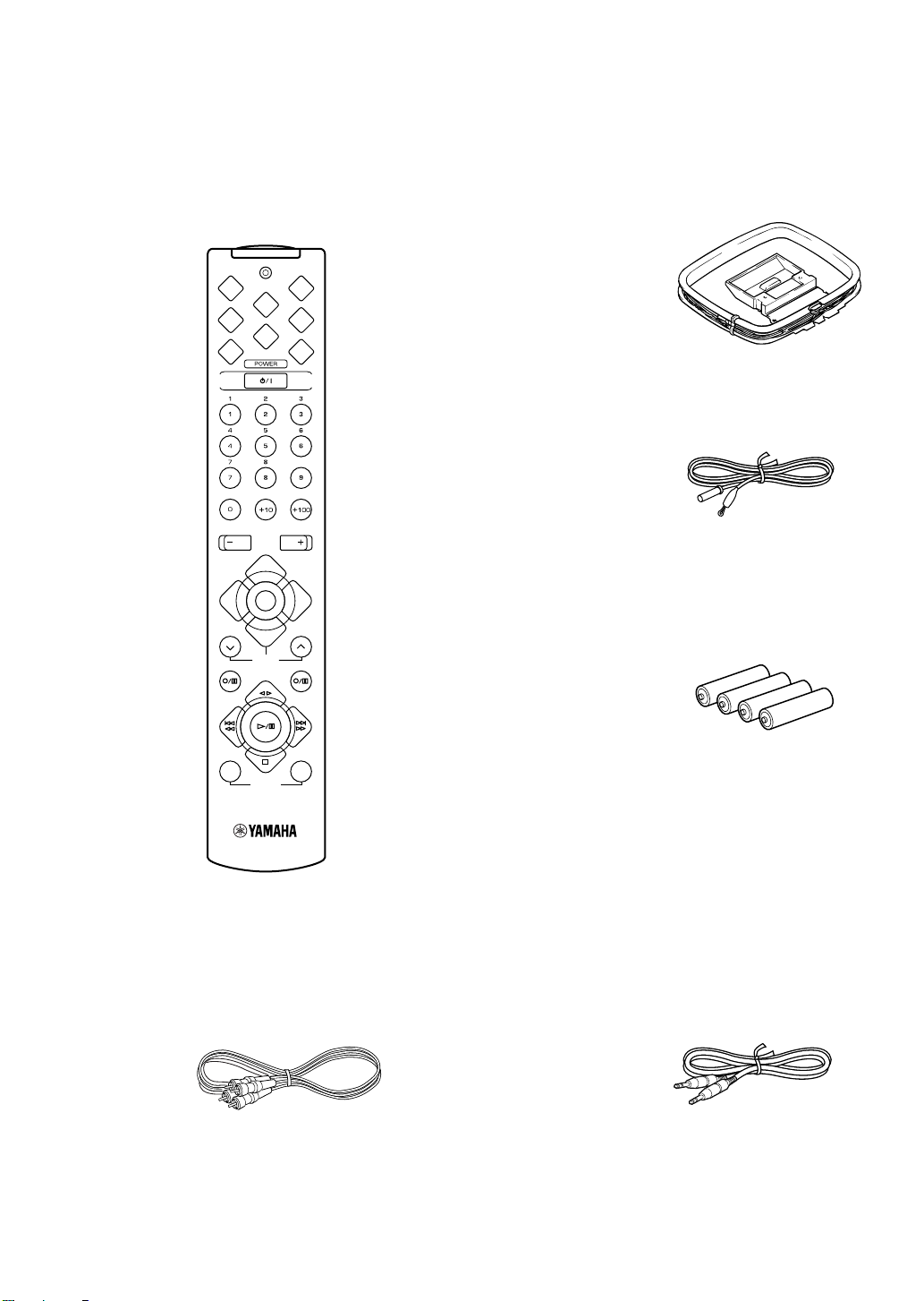
SUPPLIED ACCESSORIES • After unpacking, check that the following parts are contained.
ACCESSOIRES FOURNIS • Après le déballage, vérifier que les pièces suivantes sont incluses.
<RX-E100>
• Remote control
• Télécommande
SLEEP
TIME
A
REP
B
RNDM
D
PEAK
MODE START
VOLUME
TAPE
MD CD
AUX
TUNER
PRESET
MD REC
TAPE
DISP
C
PROG
E
TAPE
TAPE REC
• AM loop antenna
• Antenne cadre AM
• Indoor FM antenna
• Antenne intérieure FM
• Batteries (size AAA, UM-4, R03)
• Piles (format AAA, UM-4, R03)
MODE START
DUBBING
<CDX-E100>
• RCA Pin Cable
• Câble de raccordement RCA
4
• System Control Cable
• Câble de commande du système

ENGLISH
INTRODUCTION
Thank you for purchasing this YAMAHA product. We hope it will give you many years of trouble-free enjoyment. For the
best performance, read this manual carefully. It will guide you in operating your YAMAHA product.
FEATURES
<RX-E100>
• Minimum RMS Output Power per Channel
40 W + 40 W (6Ω, 20 - 20,000Hz, 0.1% THD)
• Full Operation System Remote Control
• 40-Station FM/AM Preset Tuning
• SUBWOOFER Output Terminal
The receiver (RX-E100) and CD player (CDX-E100) are the main units of the YAMAHA E100 series. You could upgrade
the system by adding the cassette deck (KX-E100) and MD recorder (MDX-E100)*.
*MD recorder (MDX-E100) may not be available for some areas.
<CDX-E100>
• S-bit DAC and 8fs Digital Filter
• Optical Digital Output
• Random, Repeat, and Program Play
• CD TEXT Display
• Peak Level Search
• Tape Programming
English
CONTENTS
PRECAUTIONS...................................................2
GETTING STARTED
The remote control ............................................... 3
Connecting the speakers .......................................4
Connecting the system..........................................5
<RX-E100>
NAMES OF BUTTONS AND CONTROLS ....... 6
BASIC OPERATIONS
Listening to a source.............................................8
TUNER OPERATIONS
Listening to the radio............................................ 9
Presetting stations ...............................................10
USING THE BUIL T-IN TIMER
Setting the clock ................................................. 11
Adjusting the brightness of the display .............. 11
Before using the timer ........................................12
Timer play and recording ................................... 12
Sleep timer.......................................................... 13
<CDX-E100>
NAMES OF BUTTONS AND CONTROLS .....14
COMPACT DISC PLAYER OPERATIONS
CD playback ....................................................... 16
Selecting the time display and CD TEXT .......... 17
Random-sequence play.......................................17
Repeat play ......................................................... 18
Program play ...................................................... 18
Peak level search ................................................19
ADD KX-E100 AND/OR MDX-E100 TO YOUR
SYSTEM
Operating the cassette deck, KX-E100 and MD
recorder, MDX-E100 with the remote control ... 20
Before recording .................................................21
Dubbing setting .................................................. 21
TAPE programming............................................22
ADDITIONAL INFORMATION
CD preventive care .............................................23
Troubleshooting..................................................23
Specifications ..................................................... 25
E-1

PRECAUTIONS: READ THIS BEFORE OPERATING THE UNIT
CAUTIONS
• To assure the finest performance, please read this
manual carefully. Keep it in a safe place for future
reference.
• Install your unit in a well ventilated, cool, dry, clean
place – away from windows, heat sources, vibration,
dust, moisture, or cold. To avoid humming sounds,
locate the unit away from other electrical appliances,
motors, and transformers. To prevent fire or electrical
shock, do not expose to rain and water.
• (U.K. and Europe models only)
Be sure to allow at least 10 cm of ventilation space at
the top, on left, right, and back sides of RX-E100.
• Do not operate the unit upside-down. It may overheat,
possibly causing damage.
• Never open the cabinet. If something drops into the set,
contact your dealer.
• Do not use force on switches, knobs or cords.
• Always set the VOLUME control to minimum before
starting playback of an audio source: increase the
volume gradually to an appropriate level after play has
started.
• When not planning to use this unit for long periods of
time (i.e., vacation, etc.), disconnect the AC power plug
from the wall outlet.
• Grounding or polarization – Precautions should be taken
so that the grounding or polarization of the unit is not
defeated.
• Do not clean the unit with chemical solvents; this might
damage the finish. Use a clean, dry cloth.
• Be sure to read the “Troubleshooting” section on
common operating errors before concluding that your
unit is faulty.
• Do not place another component on top of this unit, as
damage or discoloration on the surface of the unit may
result.
• To prevent damage by lightning, disconnect the power
cord from the wall outlet during an electrical storm.
• When disconnecting the power cord from the wall
outlet, grasp the plug; do not pull the cord.
• Do not plug the AC power plug to the wall outlet before
you finish all connections.
• The voltage to be used must be the same as that
specified on this unit. Using this unit with a higher
voltage than that which is specified is dangerous and
may result in a fire or other type of accident causing
damage. YAMAHA will not be held responsible for any
damage resulting from use of this unit with a voltage
other than that which is specified.
• When listening to the receiver at a high volume level for
a long time, the temperature inside the unit rises. To
prevent overheating and possible damage to this unit,
the internal fan starts running.
• Sudden temperature changes and storage or operation in
an extremely humid environment may cause
condensation inside the cabinet.
The unit is not disconnected from the AC power source
as long as it is connected to the wall outlet, even if this
unit itself is turned off. This state is called the standby
mode. In this state, this unit is designed to consume a
very small quantity of power.
CAUTION FOR CARRYING THE UNIT
Before carrying the unit, first remove all discs from
the unit, press STANDBY/ON to turn the unit off,
then disconnect the AC power plug from the wall
outlet.
VOLTAGE SELECTOR (General model
only)
The voltage selector (on the rear panel of this unit)
must be correctly set to the voltage used locally
before making any connection to the AC power
supply.
FREQUENCY STEP switch <General
model only>
Because the interstation frequency spacing differs
in different areas, set the FREQUENCY STEP
switch (located on the rear panel) according to the
frequency spacing in your area.
Before setting this switch, disconnect the AC power
plug of this unit from the AC outlet.
CAUTION
Use of controls or adjustments or performance of
procedures other than those specified herein may
result in hazardous radiation exposure.
As the laser beam used in this compact disc player is
harmful to the eyes, do not attempt to disassemble the
cabinet. Refer servicing to qualified personel only.
For Canadian Customers
To prevent electric shock, match wide blade of plug to
wide slot and fully insert.
Thes Class B digital apparatus complies with
CANADIAN ICES-003
E-2
GETTING STARTED
The remote control
This remote control controls a whole system: not only
RX-E100 but also CDX-E100. Moreover, a cassette deck
(KX-E100) and MD recorder (MDX-E100) that level up
your system can be operated by it. Operating buttons for
each unit are explained on the pages below:
Receiver, RX-E100: p.7
CD player, CDX-E100: p.15
Cassette deck, KX-E100: p.20
MD recorder, MDX-E100: p.20
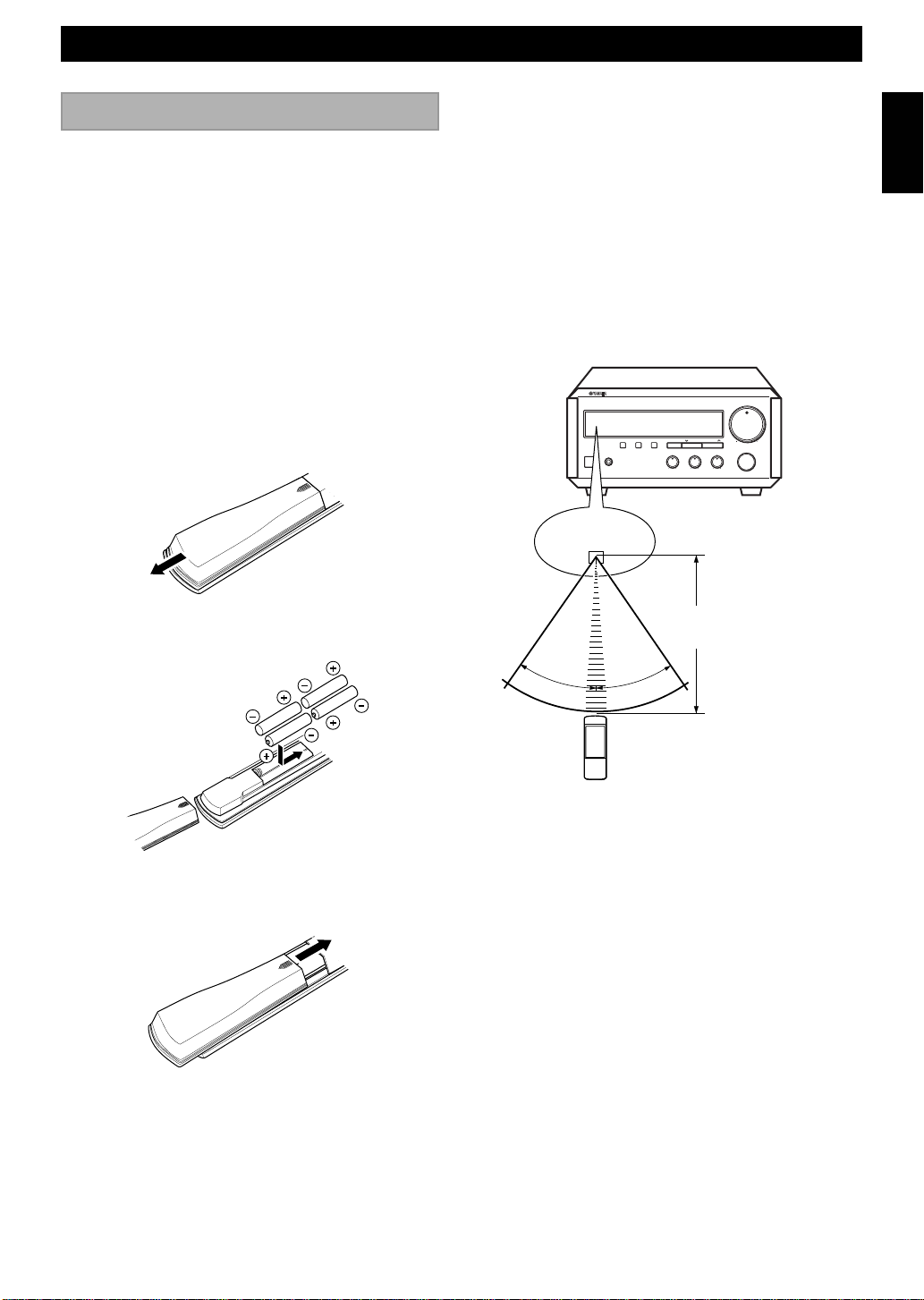
Loading the batteries for the remote control
1 Remove the battery compartment cover.
Notes
• Use only AAA, UM-4, R03 batteries for replacement.
• Be sure the polarities are correct. (See the illustration inside
the battery compartment.)
• Remove the batteries if the remote control will not be used for
an extended period of time.
• If batteries leak, dispose of them immediately. Avoid touching
the leaked material or letting it come in contact with clothing,
etc. Clean the battery compartment thoroughly before
installing new batteries.
Remote control operation range
NATURAL SOUND STEREO RECEIVER RX-E100
DISPLAY
STANDBY/ON PHONES
Remote control
sensor
MEMORY AUTO/MAN'L
TIME ADJ TIMER
HOUR MIN
BASS TREBLE BALANCE
+-+-
VOLUME
PRESET/TUNINGPRESET/BAND
RL
MAXMIN
INPUT
English
2 Insert 4 batteries into the battery compartment.
3 Replace the battery compartment cover.
Battery replacement
If you find that the remote control must be used closer to
the main unit than usual, the batteries are weak. Replace
batteries with new ones.
Within approximately
6 m (20 feet)
30°
30°
Notes
• There should be no large obstacles between the remote control
and the main unit.
• If the remote control sensor is directly illuminated by strong
lighting (especially an inverter type of fluorescent lamp, etc.),
it might cause the remote control not to work correctly. In this
case, reposition the main unit to avoid direct lighting.
E-3
GETTING STARTED
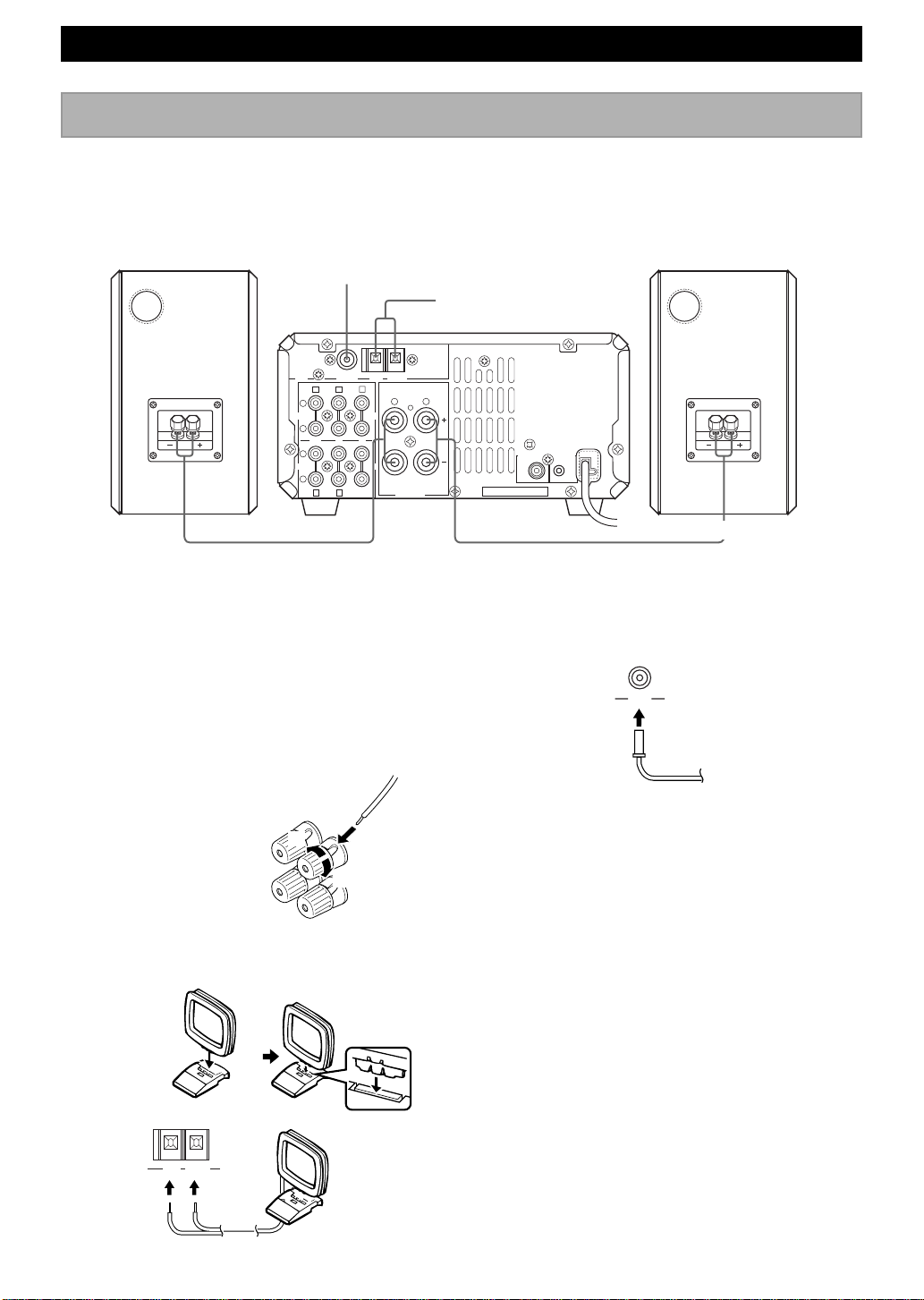
Connecting the speakers
Never plug the AC power cord to the wall outlet until all connections are completed.
Follow the steps as shown below to connect the system using the supplied cords and accessories.
Right speaker Left speaker
FM antenna
3
75 Ω UNBAL
FREQUENCY
FM ANT GND AM ANT
STEP
AB E
L
TAPE
R
OUT IN IN
L
MD
R
D
C
1 Connect the Speakers.
1 Unscrew the knob.
2 Remove approx. 5 mm (1/4”) of insulation from
each of the speaker wires and insert the bare wire
into the terminal.
3 Tighten the knob to secure the wire.
AM loop antenna
2
6 Ω MIN./SPEAKER
SPEAKERS
1
LR
SYSTEM
SUBWOOFER
CONNETOR
OUT
To wall outlet
4
CD
AUX
3 Connect the FM Antenna.
75 Ω UNBAL
FM ANT
Red: positive(+)
Black: negative(–)
2
1
3
2 Connect the AM Antenna.
Set up the AM loop antenna, then connect it.
GND AM ANT
E-4
4 Connect the AC power cord to a wall outlet.
• Use external FM/AM antennas if you need better reception.
Consult your dealer.
• The AM loop antenna should be placed apart from the main
unit. The antenna may be hung on a wall.
To Connect the Subwoofer (optional)
You can reinforce the bass frequencies by adding a
subwoofer (optional).
Connect the SUBWOOFER OUT terminal of the unit to
the INPUT terminal of the subwoofer.
GETTING STARTED
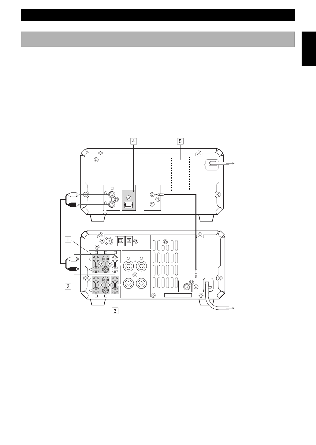
Connecting the system
Connecting RX-E100 and CDX-E100
1 Connect ‰ to ‰ using the RCA pin cable.
Insert the plugs into the jacks of the same colour.
2 Connect RX-E100 and CDX-E100 with the system control cable.
The other SYSTEM CONNECTOR of CDX-E100 is for connecting MDX-E100 or KX-E100.
3 Connect the AC power plug of CDX-E100 to AC OUTLET of RX-E100.
<CDX-E100>
3
L
R
ANALOG
DIGITAL
OPTICAL
OUT
E
OUT
SYSTEM
CONNECTOR
English
To RX-E100
RCA pin cable
1
FREQUENCY
STEP
L
TAPE
R
OUT IN IN
L
MD
R
D
75 Ω UNBAL
FM ANT GND AM ANT
AB E
CD
AUX
C
6 Ω MIN./SPEAKER
System control cable
LR
SPEAKERS
SUBWOOFER
OUT
SYSTEM
CONNETOR
<RX-E100>
2
To wall outlet
Adding KX-E100 and MDX-E100 to the above system (For details, refer to the owner's manual
supplied with the respective component.)
1 Connect Å and ı of RX-E100 to Å and ı of KX-E100.
2 Connect Ç and Î of RX-E100 to Ç and Î of MDX-E100.
3 Connect an external component to the AUX terminal of RX-E100.
4 Connect DIGITAL OPTICAL OUT of CDX-E100 to DIGITAL OPTICAL IN of MDX-E100.
Take off the covers of the optical fiber cable plug, the DIGITAL OPTICAL OUT jack, and the DIGITAL OPTICAL
IN jack before making digital connections. Be sure to replace the terminal’s cover when the terminal on the rear panel
is not being used, in order to protect from dust.
5 AC OUTLET (CDX-E100)
Connect the AC power plug of MDX-E100 or KX-E100 (Except for the UK model).
E-5
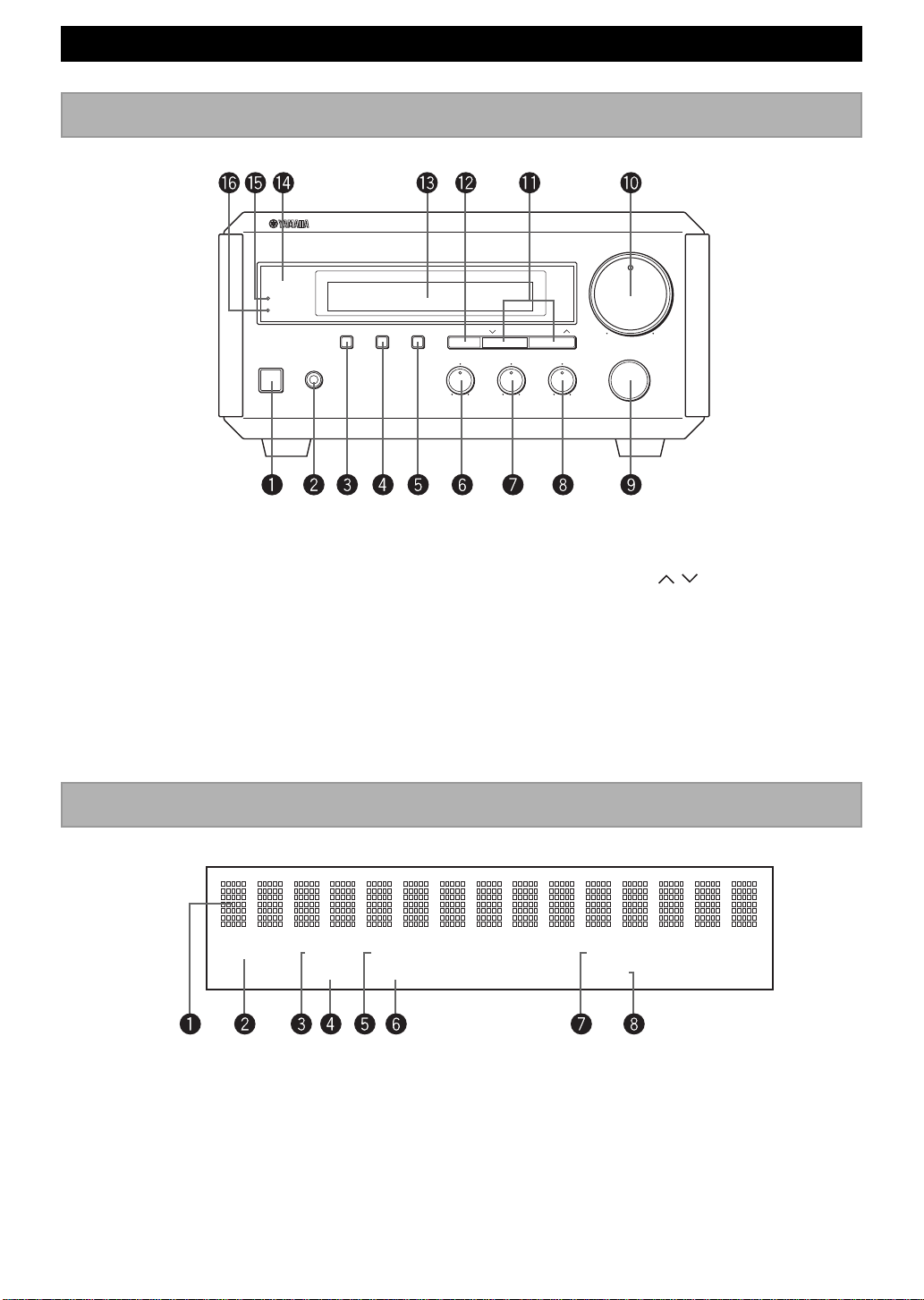
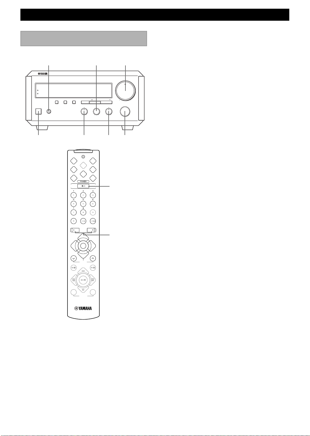
RX-E100 NAMES OF BUTTONS AND CONTROLS
Front panel
NATURAL SOUND STEREO RECEIVER RX-E100
TIMER
STANDBY
DISPLAY
STANDBY/ON PHONES
MEMORY AUTO/MAN'L
TIME ADJ TIMER
PRESET/TUNINGPRESET/BAND
HOUR MIN
BASS TREBLE BALANCE
VOLUME
MAXMIN
INPUT
~ STANDBY/ON (P.8)
Ÿ PHONES (P.8)
! DISPLAY (P.11)
⁄ MEMORY/TIME ADJ (P.10/P.11)
@ AUTO/MAN’L/TIMER (P.9/P.12)
¤ BASS (P.8)
# TREBLE (P.8)
‹ BALANCE (P.8)
$ INPUT (P.8)
+-+-
› VOLUME (P.8)
% PRESET/TUNING / (P.9)
fi PRESET/BAND (P.9)
^ Display (P.6)
fl Remote Control Sensor (P.3)
& TIMER indicator (P.12)
‡ STANDBY indicator (P.8)
Display
RL
HOUR/MIN (P.11)
PRESET
STEREO AUTO TIMER
~ Multi-information display
Ÿ PRESET indicator (P.10)
! STEREO indicator (P.9)
⁄ TUNED indicator (P.9)
E-6
SLEEPTUNED MEMORY
@ AUTO indicator (P.9)
¤ MEMORY indicator (P.10)
# TIMER indicator (P.12)
‹ SLEEP indicator (P.13)

RX-E100 NAMES OF BUTTONS AND CONTROLS
SLEEP DISP
REP
PEAK
TIME
C
B
RNDM
E
MODE START
VOLUME
TAPE
A
D
PROG
TAPE
Remote control
~ SLEEP (P.13)
Ÿ DISP (Display) (P.11)
! A/B/C/D/E (P.10)
⁄ POWER (P.8)
@ Preset numbers (P.10)
¤ VOLUME + – (P.8)
# TAPE (KX-E100) (P.20)
‹ MD (MDX-E100) (P.20)
$ AUX (The equipment connected to the AUX
terminal) (P.5)
› CD (CDX-E100) (P.16)
% TUNER (RX-E100) (P.10)
fi PRESET
Note
• #~fi are operation buttons and input selectors for each
component.
English
/ (P.10)
MD CD
AUX
TUNER
PRESET
MD REC
MODE START
TAPE REC
TAPE
DUBBING
E-7
RX-E100 BASIC OPERATIONS
Listening to a source
BASS TREBLE BALANCE
+-+-
BASS
SLEEP DISP
TIME
A
REP
B
RNDM
D
PEAK
TREBLE
PRESET/TUNINGPRESET/BAND
HOUR MIN
C
PROG
E
TAPE
RL
PHONES
NATURAL SOUND STEREO RECEIVER RX-E100
TIMER
STANTBY
STANDBY/ON PHONES
DISPLAY
MEMORY AUTO/MAN'L
TIME ADJ TIMER
STANDBY/ON INPUTBALANCE
VOLUME
VOLUME
INPUT
POWER
4 Play the source. (Refer to the owner’s manual
supplied with each selected component.)
5 Adjust the volume level by turning VOLUME on the
front panel or pressing VOLUME + on the remote
control.
6 If desired, adjust BASS, TREBLE, and BALANCE.
MAXMIN
BASS: Turn this control clockwise to increase (or
counterclockwise to decrease) the low frequency
response.
TREBLE: Turn this control clockwise to increase (or
counterclockwise to decrease) the high frequency
response.
BALANCE: Adjust the balance of the output volume
from the left and right speakers to compensate for
sound imbalance caused by the speaker location or
listening room conditions
• These controls are only effective for the sound from the main
speakers.
VOLUME
TAPE
MD CD
AUX
TUNER
PRESET
MD REC
TAPE REC
TAPE
MODE START
DUBBING
VOLUME –/+
1 Set the volume to “MIN” by turning VOLUME.
2 Turn on the power by pressing STANDBY/ON on
the front panel, or POWER on the remote control.
• RX-E100 can be used to turn on or put in standby mode
the system connected E100 series components depending
on their prior standby/on status.
3 Select the desired input source by turning INPUT so
that the source appears on the display.
• When you operate the component connected to the AUX
terminal, turn INPUT to select AUX.
When you use headphones
Connect the headphones to the PHONES jack. You can
listen to the sound from the main speakers through the
headphones.
When you have finished using this
unit
Press STANDBY/ON on the front panel again or
POWER on the remote control to set this unit to the
standby mode.
• The STANDBY indicator lights up.
Auto power off function
RX-E100 will be put automatically into the standby mode
under the following conditions:
• The component connected to RX-E100 is in stop mode
and not operated for 30 minutes.
• TUNER or AUX is not selected as an input source.
E-8
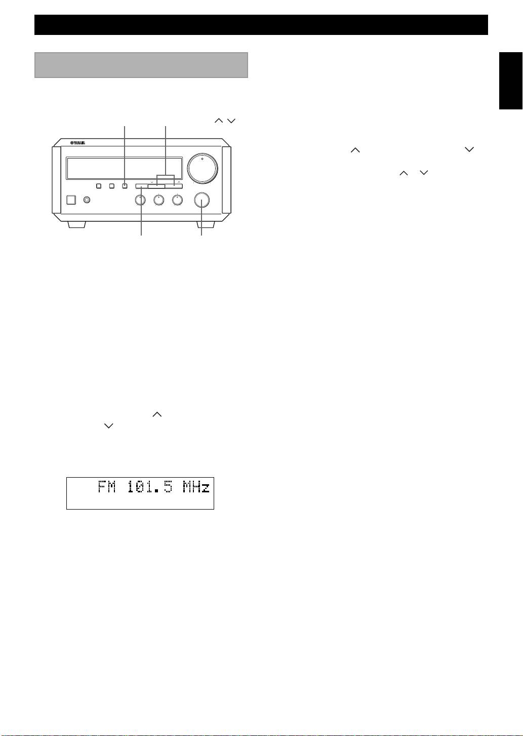
TUNER OPERATIONS
Listening to the radio
You can find radio stations automatically and manually.
AUTO/MAN’L
NATURAL SOUND STEREO RECEIVER RX-E100
MEMORY AUTO/MAN'L
DISPLAY
STANDBY/ON PHONES
TIME ADJ TIMER
PRESET/BAND
Automatic tuning
1 Select TUNER by turning INPUT so that the
frequency of a radio station appears in the display.
2 Press PRESET/BAND to select the reception band.
Do not select the preset tuning mode (in which
“PRESET” appears on the display).
PRESET/TUNING /
PRESET/TUNINGPRESET/BAND
HOUR MIN
BASS TREBLE BALANCE
+-+-
RL
INPUT
VOLUME
INPUT
MAXMIN
Manual tuning
1 Follow steps 1 and 2 described in “Automatic
tuning.”
2 Press AUTO/MAN’L so that “AUTO” disappears
from the display.
3 Press TUNING
(For a lower frequency) to select your desired station.
• Each time you press TUNING
changes step by step.
(For a higher frequency) or
or , the frequency
English
3 Press AUTO/MAN’L so that “AUTO” appears in the
display.
4 Press PRESET/ TUNING (For a higher
frequency) or
(For a lower frequency).
5 The unit starts searching for a station.
STEREO AUTO
TUNED
When the unit finds a station, the unit stops searching
and “TUNED” appears on the display.
6 If the located station is not the one you want, repeat
steps 4 and 5 until a station you want is tuned.
Notes
• If automatic tuning search does not find the desired station, try
manual tuning as described next.
• When an FM stereo broadcast with sufficient signal strength is
received, “STEREO” appears on the display and you can listen
to stereo sound.
E-9

TUNER OPERATIONS
Presetting stations
The unit can preset station frequencies selected by
Automatic tuning or Manual tuning. Up to 40 stations can
be stored. With this function, you can select any desired
station by pressing the corresponding preset station
number.
PRESET/TUNING /
NATURAL SOUND STEREO RECEIVER RX-E100
MEMORY AUTO/MAN'L
STANDBY/ON PHONES
DISPLAY
TIME ADJ TIMER
PRESET/TUNINGPRESET/BAND
HOUR MIN
BASS TREBLE BALANCE
+-+-
To preset stations manually
1 Tune in a desired station.
(Refer to the previous page for the tuning procedure.)
2 Press MEMORY.
3 Within about 5 seconds, use PRESET/TUNING
/ to select a desired preset number. Continue
pressing PRESET/TUNING
group of the preset stations (A, B, C, D, and E).
VOLUME
MAXMIN
INPUT
RL
INPUTPRESET/BANDMEMORY
/ to select the
5 Repeat steps 1 to 4 until all desired stations are
preset.
Notes
• A new setting can be preset in place of a previous one.
• The preset stations are retained for a week after you disconnect
the AC power cord or a power failure occurs.
To preset stations automatically
1 Select TUNER as input source by turning INPUT.
2 Press MEMORY for about 2 seconds.
• The unit starts presetting stations, “AUTO” and
“MEMORY” will flash on the display.
Received stations are stored to A1, A2...A8 sequentially.
After 40 stations or all FM and AM stations are stored, the
display will show the preset station A1.
To recall a preset station
Press TUNER and select the desired number by pressing
PRESET/BAND and PRESET/TUNING
front panel or PRESET
/ , A/B/C/D/E and 1-8 on
the remote control.
SLEEP DISP
TIME
A
D
C
REP
PEAK
PROG
B
RNDM
E
TAPE
/ on the
A/B/C/D/E
STEREO
PRESET
TUNED
MEMORY
4 Press MEMORY.
•“MEMORY”, “PRESET”, and preset number will appear
on the display.
The arrow will appear for a second when
it is preset.
STEREO
PRESET
TUNED
MEMORY
E-10
TUNER
PRESET
VOLUME
TAPE
MD CD
AUX
TUNER
PRESET
MD REC
TAPE REC
TAPE
MODE START
DUBBING
1~8

USING THE BUILT-IN TIMER
Setting the clock
You must set the clock before you use the timer functions.
The clock is based on a 24-hour system for Australia and
General models, and 12-hour system for US, Canada, and
General models.
HOURDISPLAY
NATURAL SOUND STEREO RECEIVER RX-E100
DISPLAY
MEMORY AUTO/MAN'L
TIME ADJ TIMER
STANDBY/ON PHONES
BASS TREBLE BALANCE
PRESET/BANDTIME ADJ
1 While the power is on, press DISPLAY to display
the time.
2 While holding TIME ADJ, press HOUR to set the
hour.
• If you want to move the time in the reverse direction,
press HOUR while holding TIME ADJ and PRESET/
BAND.
MIN
PRESET/TUNINGPRESET/BAND
HOUR MIN
+-+-
RL
VOLUME
INPUT
MAXMIN
Adjusting the brightness
of the display
You can adjust the brightness of the display. If you have
connected the CD player (CDX-E100), cassette deck
(KX-E100), and/or MD recorder (MDX-E100) to this
unit, the brightness of the displays is automatically
adjusted to that of this unit.
DISPLAY
NATURAL SOUND STEREO RECEIVER RX-E100
MEMORY AUTO/MAN'L
STANDBY/ON PHONES
DISPLAY
TIME ADJ TIMER
PRESET/TUNINGPRESET/BAND
HOUR MIN
BASS TREBLE BALANCE
+-+-
Press and hold DISPLAY for about two seconds so that
“Dimmer ±0” appears on the display. While holding
DISPLAY, turn INPUT clockwise to increase or
counterclockwise to decrease brightness.
RL
VOLUME
INPUT
INPUT
MAXMIN
English
3 While holding TIME ADJ, press MIN to set the
minutes.
• If you want to move the time in the reverse direction,
press MIN while holding TIME ADJ and PRESET/
BAND.
To display the clock
Press DISPLAY.
The current time appears for about 8 seconds, then the
normal display returns.
Note
• In the event of a power failure or when the AC power cord is
disconnected for more than five minutes, you must reset the
clock.
Control Range: ±0 to –6 (Preset value: ±0)
E-11

USING THE BUILT-IN TIMER
Before using the timer
If you want to use the cassette deck, KX-E100 or the MD
Recorder, MDX-E100 for timer play or recording, you
must first make the connections as shown in “Connecting
the system” on page 5. For details, refer to the instructions
supplied with the MDX-E100 or KX-E100.
Timer play and recording
By using the built-in timer, you can have the unit turn on
at a specified time and begin playing or recording
automatically. You can also specify the turn off time.
DISPLAY
NATURAL SOUND STEREO RECEIVER RX-E100
DISPLAY
STANDBY/ON PHONES
MEMORY AUTO/MAN'L
TIME ADJ TIMER
BASS TREBLE BALANCE
MIN
PRESET/TUNINGPRESET/BAND
HOUR MIN
+-+-RL
HOURTIMER
VOLUME
INPUT
INPUT
MAXMIN
3. Timer REC
Select the recording component by turning INPUT.
If you like to enjoy timer play with TUNER or
AUX, select “REC Mode OFF”.
(Example)
4. ON Time
“ON Time” appears on the display for a second,
and changed to the time setting mode.
Press HOUR to set the hour.
Press MIN to set the minute.
5. OFF Time
Set the time the same way as above.
If you set the ON time but not OFF time, the timer
play or recording will finish automatically after an
hour.
Notes
• The display mode will change in about 8 seconds. If the
mode is changed before the setting is completed, call the
mode again by pressing DISPLAY once or more.
• If you select the input other than TUNER and AUX on
“2. Timer Input”, “3. Timer REC” is skipped.
1 Press DISPLAY.
Whenever DISPLAY is pressed, the display mode
changes as follows:
1. Clock Time (TIMER on/off mode)
If you have not set the clock yet “Set Clock”
appears. You need to set the current time as
described on page 11.
2. Timer Input
Select the source to be played by turning INPUT.
• Timer recording is possible only when you select
TUNER or AUX.
E-12
2 Press TIMER to complete the timer setting.
The system is put in the standby mode.
• The STANDBY and TIMER indicators light up.
If you continue using the system, press STANDBY/
ON to turn on this unit.
To cancel the timer play setting
Press DISPLAY to show the current time, then press
TIMER so that “TIMER” goes off from the display. You
can also cancel by pressing TIMER in standby mode.
Note
• In the event of a power failure or when the AC power cord is
disconnected for more than five minutes, you must reset the
clock.

USING THE BUILT-IN TIMER
Sleep timer
The unit can be turned off automatically at a selected
SLEEP time.
A
D
SLEEP
REP
PEAK
B
SLEEP
1 Play the desired sound source.
2 Press SLEEP repeatedly until the desired sleep time
appears in the display.
Each time you press SLEEP, the sleep time changes
as follows:
TIME
RNDM
DISP
C
PROG
E
TAPE
3 The unit will turn off automatically when the selected
sleep time is reached.
English
SLEEP 2h00m
SLEEP 1h30m
SLEEP 1h00m
SLEEP 0h30m
SLEEP OFF
About 4 seconds after setting, the normal display will
resume.
• “SLEEP” will appear in the display.
Downloaded from:
E-13

CDX-E100 NAMES OF BUTTONS AND CONTROLS
Front panel
NATURAL SOUND COMPACT DISC PLAYER CDX-E100
STANDBY/ON
~ STANDBY/ON (P.16)
Ÿ Display (this page)
! $/! (Skip/Search Backward)
⁄/› (Skip/Search Forward) (P.16)
REPEAT
SF
TITLE ARTIST TRACK CD-TEXT
PROGRAM
⁄^ (Play/Pause) (P.16)
@ & (Stop) (P.16)
¤ (Open/Close) (P.16)
# Disc Tray (P.16)
Display
123456789
11 12 13 14 15 16 17 18 19 20
ABRANDOM
10
~ Multi-information Display
Ÿ * Pause indicator
! # Play indicator
⁄ A
B Tape side indicator (P.22)
@ Music calendar
E-14
¤ RANDOM indicator (P.17)
# PROGRAM indicator (P.18)
‹ REPEAT S/F (Single or Full) indicator (P.18)
$ CD-TEXT indicator (P.17)

CDX-E100 NAMES OF BUTTONS AND CONTROLS
SLEEP
A
D
PEAK
REP
TIME
B
RNDM
VOLUME
TAPE
C
E
DISP
PROG
TAPE
Remote control
English
~ TIME (P.17)
Ÿ REP (Repeat) (P.18)
! PROG (Program) (P.18)
⁄ RNDM (Random) (P.17)
@ PEAK (Peak Search) (P.19)
¤ TAPE (P.22)
# POWER (P.16)
‹ Numeric buttons (P.16)
$ CD input (P.16)
› $/! (Skip/Seach Backward) (P.16)
% ›/⁄ (Skip/Seach Forward) (P.16)
fi ^ (Play/Pause) (P.16)
^ & (Stop) (P.16)
MD
AUX
TUNER
PRESET
MD REC
MODE START
TAPE REC
TAPE
DUBBING
CD
E-15

COMPACT DISC PLAYER OPERATIONS
CD playback
NATURAL SOUND COMPACT DISC PLAYER CDX-E100
STANDBY/ON
STANDBY/ON
$/!/›/⁄
To play CDs
SLEEP
TIME
A
REP
B
RNDM
D
PEAK
VOLUME
TAPE
MD
AUX
TUNER
PRESET
MD REC
TAPE
MODE START
DUBBING
DISP
C
PROG
E
TAPE
CD
TAPE REC
POWER
Numeric
buttons
CD
^
&
3 Press
to open the disc tray, and place a CD on the
tray.
^&
00
1
-E
X
D
C
ER
Y
A
L
P
C
IS
D
T
C
PA
M
O
C
D
N
U
O
S
L
A
R
U
T
A
N
STANDBY/ON
4 Press ^ to start playback.
The unit starts playback of the CD.
To pause playback
⁄/›$/!
Press ^.
To resume play, press ^ again.
To stop playback
Press &.
To eject the CD
Press
to open the disc tray, and remove the CD from
the tray.
To play a specific track on the disc
(Skip)
Direct play
Select a desired track using the numeric button.
(Example: To select 35, press +10 three times so that
“3 –” appears in the display, then press 5.)
Skip play
Press › to skip forward or $ to skip backward. Press
once for each track to be skipped.
Notes
• You cannot enter a number that is higher than the last track
number on the disc.
• These operations can also be performed when the unit is in the
pause or stop mode.
• During stop mode, if › or $ is pressed, the track number
successively changes to higher numbers (or lower numbers).
1 Press STANDBY/ON to turn on this unit and also
RX-E100.
2 Press CD on the remote control in order to operate
the CD player by the remote control.
E-16
To advance or reverse playback
rapidly (Search)
Press and hold ⁄ to advance playback rapidly, and !
to reverse playback rapidly.
COMPACT DISC PLAYER OPERATIONS
Selecting the time display
and CD TEXT
You can select any of four time displays by pressing
TIME. When you play a CD with CD TEXT, the disc
title, artist name, and track name are also displayed.
SLEEP
A
REP
B
D
PEAK
Each time you press TIME, the display changes as
follows:
DISP
TIME
C
PROG
RNDM
E
TAPE
Elapsed time of the
current track
Remaining time of the
current track
Total disc play time
Total remaining time of
the disc
TIME
Random-sequence play
The unit can play all the tracks in a random sequence.
SLEEP
A
REP
D
PEAK
Press RNDM.
• “RANDOM” appears on the display.
The unit starts random sequence play.
To cancel random-sequence play
mode
Press & or RNDM.
• “RANDOM” disappears from the display.
Notes
• This feature will not function during programming, or during
programmed play.
• If › is pressed during random-sequence play, the next
randomly programmed track will be played.
If $ is pressed, play will return to the beginning of the
current track.
• Total remaining time on the disc will not be displayed during
random-sequence play.
TIME
B
RNDM
DISP
C
PROG
E
TAPE
RNDM
English
• “CD-TEXT” appears on the display if a
CD has CD TEXT.
Disc title
Artist name
Track name
Note
• The disc title, artist names, or track names may not be
displayed with some CD TEXT discs. In this case, “(NO
ENTRY)” appears on the display.
E-17

COMPACT DISC PLAYER OPERATIONS
Repeat play
You can play any desired track or disc repeatedly.
Press REP to select the repeat mode.
SLEEP
A
REP
REP
B
D
PEAK
SINGLE REPEAT
The current track is played repeatedly.
REPEAT S
FULL REPEAT
The current disc is played repeatedly.
• In random-sequence play mode, all randomly sequenced tracks
are played repeatedly in the same order.
TIME
RNDM
DISP
C
PROG
E
TAPE
Program play
By creating a program, you can enjoy listening to your
favourite tracks in any desired order. As many as 30
tracks can be programmed in sequence.
SLEEP
A
REP
D
PEAK
MD
MD REC
MODE START
TIME
B
RNDM
VOLUME
TAPE
AUX
TUNER
PRESET
TAPE
DUBBING
DISP
C
PROG
E
TAPE
CD
TAPE REC
PROG
Numeric
buttons
› / $
^
&
REPEAT F
To cancel repeat play mode
Press REP successively until “REPEAT F” disappears
from the display.
E-18
1 Press & to stop the unit.
2 Press PROG.
• “PROGRAM” appears in the display.
PROGRAM
3 Use the numeric buttons to select a track number
until the desired track number appears on the display.
PROGRAM
4 Repeat step 3 to program more tracks. You can select
the same track again.
5 Press ^ to start program play.

COMPACT DISC PLAYER OPERATIONS
To stop program play mode
Press &.
Note
• › or $ can be used during program play to skip to tracks
within the program.
To check program data
1. Press & to stop program play.
2. Press PROG. Then each time you press › /
$,
the track number and the program number are
displayed in the order of the program.
To change program data
1. Follow the preceding procedure described in “To
check program data.”
2. Display the track number to be changed by pressing
› /
$.
3. Press the numeric button of the desired track. The
previously programmed track will be cleared from
memory and the new one will be programmed.
Peak level search
This unit can find the peak sound level on the CD for
optimum adjustment of the recording volume level.
SLEEP
A
REP
B
D
PEAK
PEAK
Press PEAK while the player is stopped or the tray is
opened.
• It takes a few minutes to search for the peak level. When
found, the unit plays the peak level for 4 seconds repeatedly.
To cancel searching
TIME
RNDM
DISP
C
PROG
E
TAPE
English
To delete all program data
When program play is stopped, press &.
Press &.
E-19

ADD KX-E100 AND/OR MDX-E100 TO YOUR SYSTEM
Operating the cassette deck, KX-E100 and MD
recorder, MDX-E100 with the remote control
MDX-E100
SLEEP
A
D
MD REC
TIME
REP
B
RNDM
PEAK
VOLUME
TAPE
MD CD
AUX
TUNER
PRESET
TAPE
DISP
C
PROG
E
TAPE
TAPE REC
~ TIME (Same function as DISPLAY on
MDX-E100 remote control)
Ÿ REP (Repeat)
! PROG (Program)
⁄ RNDM (Random)
@ POWER
,
¤ Numeric buttons
# MD input
‹ MD REC/PAUSE
$ $/! (Skip/Search Backward)
› ›/⁄ (Skip/Search Forward)
% & (Stop)
fi ^ (Play/Pause)
KX-E100
1 POWER
*
2 TAPE input
3 TAPE REC/PAUSE
4 @# (Tape Direction)
5 $/! (Rewind/Music Search Backward)
6 ›/⁄ (Fast Forward/Music Search Fast
Forward)
7 & (Stop)
8 ^ (Play)**
,
,
,,
MODE START
DUBBING
E-20
* Input selectors when recording.
**There is no pause function on KX-E100.

ADD KX-E100 AND/OR MDX-E100 TO YOUR SYSTEM
Before recording
When you record by using MDX-E100 or KX-E100, you
must first make the connections as shown in “Connecting
the system” on page 5. For details, refer to the instructions
supplied with the MDX-E100 or KX-E100. A source from
the component which is connected to the AUX terminal
component can be recorded on a tape or MD.
Dubbing setting
There are six different combinations of components. Once
you choose a certain mode, recording starts and ends
automatically in a certain way for each mode.
MD REC
TAPE REC
TAPE
2
• Only the first track is recorded. After recording the
CD tray opens automatically.
3
4
• Same as CD (Tr1) = TAPE
5
Play unit
Record unit
English
DUBBING
MODE
MODE START
DUBBING
DUBBING
START
1 Decide the combination of the components. Each
time you press DUBBING MODE, the mode will
change in the below order.
1
• Recording automatically starts from the beginning
of the tape. (By pressing DUBBING START, the
tape automatically rewinds to the beginning if it is
in the middle.)
• When the recording on side A finishes while a
track is being played back, the recording on side B
starts from the beginning of the same track.
• The sound is automatically faded out when it gets
close to the end of side B.
• Same as CD = TAPE
6
• Recording automatically starts at the beginning of
the tape. (By pressing DUBBING START, the
tape automatically rewinds to the beginning if it is
in the middle.)
Play unit
Record unit
2 Press DUBBING START to start recording.
Note
• The displays 1~6 which include the component you have not
connected to your receiver (RX-E100) will be skipped.
E-21

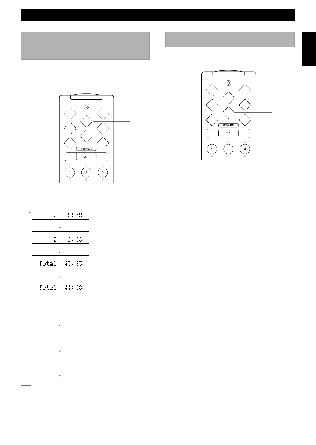
ADD KX-E100 AND/OR MDX-E100 TO YOUR SYSTEM
3 Press PROG to start programming.
TAPE Programming
• “A
B” appears in the display to indicate the direction
of the tape.
By specifying the length of the tape, the CD player,
CDX-E100 programs tracks or helps you to program
tracks so they will fit onto the tape with the least amount
of unrecorded space remaining at each end of the tape.
There are three ways of programming.
1 Manual TAPE programming
REP
RNDM
SLEEP
A
REP
D
PEAK
MD CD
MD REC
TIME
B
RNDM
VOLUME
TAPE
AUX
TUNER
PRESET
TAPE
DISP
C
PROG
E
TAPE
TAPE REC
PROG
TAPE
4 Select the desired track number using numeric
buttons.
• Repeat step 4 to continue programming tracks.
• The remaining time is shown on the display. If the track is
longer than the remaining time, “Error” appears on the
display.
5 Press TAPE to continue programming tracks on side
B.
• Repeat step 4.
6 Press PROG to confirm the program.
7 Choose CD = TAPE by pressing DUBBING
MODE, and press DUBBING START to start
recording.
2 Automatic TAPE programming
1 Repeat steps 1 and 2 of “Manual TAPE
programming”.
2 Press REP to start programming.
• Programming is done in the order on the CD from side A
to side B. When complete, the programmed track number
and total time are indicated in the display for 3 seconds.
DUBBING
MODE
MODE START
DUBBING
DUBBING
START
1 Insert the desired disc into the CD player, and load a
blank tape into the KX-E100.
2 Press TAPE repeatedly to select the length of tape to
be used. Each time you press TAPE, the length of the
tape changes as follows:
46 54
90 60
• You can use numeric buttons to input the length of the
tape.
E-22
3 Press PROG to confirm the program.
4 Choose CD = TAPE by pressing DUBBING
MODE, and press DUBBING START to start
recording.
3 Random TAPE programming
1 Repeat steps 1 and 2 of “Manual TAPE
programming”.
2 Press RNDM to start programming.
• Programming of CD tracks is done randomly from side A
to side B. When complete, the programmed track number
and total time are indicated in the display for 3 seconds.
3 Press PROG to confirm the program.
4 Choose CD = TAPE by pressing DUBBING
MODE, and press DUBBING START to start
recording.

ADDITIONAL INFORMATION
CD preventive care
• This compact disc player is designed for playing
compact discs bearing the
attempt to load any other type of disc into the unit.
The unit will also play 8-cm (3-inch) compact discs.
• Compact discs are not subjected to wear during play,
but damage to the disc surface when the disc is being
handled can adversely affect the disc’s play.
• Do not use cleaning discs or warped discs. All of these
could damage the unit.
To prevent a malfunction of this unit
• Do not use any non standard shaped CD (heart, etc.)
available on the market, because it may damage the
unit.
• Do not use a CD with tape, seals, or paste on it, because
damage to the unit may result.
or mark only. Never
English
• Compact discs are not affected by small particles of
dust or fingerprints on their playing surface, but even so
they should be kept clean. Wipe by using a clean, dry
cloth. Do not wipe with a circular motion; wipe straight
outward from the center.
• Do not try to clean the disc’s surface by using any type
of disc cleaner, record spray, antistatic spray or liquid,
or any other chemical-based liquid, because such
substances might irreparably damage the disc’s surface.
• Do not expose discs to direct sunlight, high temperature
or high humidity for a long period of time, because
these might warp or otherwise damage the disc.
No!
Troubleshooting
If the unit fails to operate normally, check the following points to determine whether the fault can be corrected by the
simple measures suggested. If it cannot be corrected, or if the fault is not listed in the SYMPTOM column, disconnect the
power cord and contact your authorized YAMAHA dealer or service center for help. When taking the service, the
MDX-E100 or KX-E100 may be needed. For details, contact your authorized YAMAHA dealer or service center.
SYMPTOM CAUSE REMEDY
The unit does not switch ON when
the STANDBY/ON switch is pressed.
No sound from one speaker.
No sound from speakers.
No sound from an external unit
connected with this unit or play does
not begin.
RX-E100 RECEIVER
The AC power cord is not connected or not
completely connected.
Loose speaker connections.
Internal protection circuit is functioning.
Incorrect cord connections.
Input source selection is not proper.
Securely connect the power cord.
Connect properly.
Unplug the AC power cord from the wall outlet, and
then plug in again.
Connect the cords properly. If the problem persists,
the cords may be defective.
Make a proper input source selection.
E-23

ADDITIONAL INFORMATION
SYMPTOM CAUSE REMEDY
Excessive static in FM broadcasts.
Noise increases during stereo
broadcasts.
Stereo broadcasts are noisy and
STEREO indicator blinks on and off.
Cannot select preset stations.
Buzzing or static during AM
broadcasts.
RX-E100 RECEIVER
AM broadcast sensitivity is poor.
Cannot set timer.
The unit does not work normally.
Play does not begin.
Play is delayed, or begins at the
wrong place.
CD synchronized recording or
Automatic recording function does
not work.
Sound “skips.”
Sound “hums.”
Noise from inside of the unit.
The remote control does not work.
TV functions strangely when the
REMOTE CONTROL CDX-E100 CD PLAYER
remote control is being used.
Interference from starting motor of a nearby
car.
Interference from the thermostat of a nearby
electrical appliance.
Antenna input is too weak due to obstructions
or excessive distance from the broadcasting
station.
Insufficient antenna input.
Preset memory has been erased.
Interference from sources such as lightning,
fluorescent lights, electric motors or
thermostat of nearby electrical appliance.
TV or microprocessor is being used nearby.
Radio signal is weak or the antenna is not
properly connected.
Current time is not set.
The internal microcomputer has been frozen
by an external electric shock (lightning,
excessive static electricity, etc.) or the power
supply with low voltage.
The disc is damaged.
There is moisture on the laser pick-up.
The disc has been loaded upside down.
The disc is dirty.
The disc may be scratched or damaged.
The system cable is not connected securely.
The unit is being subjected to vibrations or
impacts.
The disc is dirty.
Improper cable connections.
The disc may be warped.
The batteries of the remote control are too
weak.
Remote control is too far away or is being
used at an incorrect angle.
Direct sunlight or lighting (of an inverter type
of fluorescent lamp, etc.) is striking the
remote control sensor of the unit.
Remote control is being used near TV set
with a remote control sensor.
Position the FM antenna as high and as far away
from nearby roads as possible. Connect using a
coaxial cable.
Check the antenna connection.
Install a multi-element type FM antenna if possible.
Install an antenna appropriate for the electric field
strength of your area.
Reprogram memory presets.
The problem is difficult to eliminate, but can be
lessened by grounding AM loop antenna.
Move away from TV or microprocessor.
Properly connect the AM loop antenna.
Change orientation of the AM loop antenna.
Install an external AM loop antenna.
Set current time.
Unplug the AC power cord from the wall outlet, and
then plug in again after about one minute.
Check the disc carefully; replace it if necessary.
Wait 20 to 30 minutes after switching the unit ON
before trying to play a disc.
Reload the disc with the label side facing up.
Clean the disc.
Check the disc carefully; replace it if necessary.
Connect the system cable properly.
Relocate the unit.
Clean the disc.
Securely connect the audio cables. If the problem
persists, the cables may be defective.
Replace the disc.
Replace the batteries with new ones.
Use within 6 meters and 60 degree radius.
Change the position of the unit.
Relocate this unit away from the TV or cover the
TV’s remote control sensor.
E-24

ADDITIONAL INFORMATION
Specifications
<RX-E100>
Amplifier section
Minimum RMS output power per channel
.............................................. 50 W + 50 W (6Ω 1kHz 0.07% THD)
.................................. 40 W + 40 W (6Ω 20 - 20,000Hz 0.1% THD)
DIN Standard output power per channel (Europe model)
................................................ 60 W + 60 W (4Ω 1kHz 0.7% THD)
Input sensitivity/Impedance
CD/TAPE/MD/AUX
............................................................................ 150 mV/47 k-ohms
Tuner section
Tuning range
FM
[U.S.A. and Canada models]
..............................................................................87.5 – 107.9 MHz
[U.K., Europe, Australia, and General models]
..........................................................................87.50 – 108.00 MHz
AM
[U.S.A. and Canada models]
................................................................................. 530 – 1710 kHz
[U.K., Europe, and Australia models]
................................................................................. 531 – 1611 kHz
[General model]
................................................................. 530/531 – 1710/1611 kHz
Sensitivity
FM (S/N 30dB)
................................................................................................1.5 µV
FM (S/N 26dB) (DIN)
................................................................................................1.8 µV
AM
.......................................................................................... 300 µV/m
General
Power supply
[U.S.A. and Canada models]
............................................................................... AC 120 V, 60 Hz
[Australia model]
............................................................................... AC 240 V, 50 Hz
[U.K. and Europe models]
............................................................................... AC 230 V, 50 Hz
[General model]
.................................................... AC 110/120/220/240 V, 50/60 Hz
Power consumption
[U.S.A. and Canada models]
................................................................................................ 110 W
[U.K., Europe, Australia, and General models]
................................................................................................ 100 W
Dimensions (W x H x D)
..........................................................................217 x 108 x 312 mm
Weight
................................................................................................. 4.5 kg
Accessories
.................................................................................. Remote control
Batteries
Indoor FM antenna
AM loop antenna
English
<CDX-E100>
CD player section
D/A converter
..........................................................................................S-bit DAC
Frequency response (2 – 20,000 Hz)
............................................................................................. ±0.5 dB
S/N ratio
............................................................................................... 102 dB
Laser Diode Properties
• Material: GaAIAs
• Wavelength: 780 nm
• Emission duration: continuous
• Laser output: max. 44.6 µW*
* This output is the value measured at a distance of about 200 mm
from the objective lens surface on the Optical Pick-up Block.
General
Power supply
[U.S.A. and Canada models]
............................................................................... AC 120 V, 60 Hz
[Australia model]
............................................................................... AC 240 V, 50 Hz
[U.K. and Europe models]
............................................................................... AC 230 V, 50 Hz
[General model]
.................................................... AC 110/120/220/240 V, 50/60 Hz
Power consumption
.................................................................................................. 13 W
Dimensions (W x H x D)
..........................................................................217 x 108 x 290 mm
Weight
................................................................................................. 3.0 kg
Accessories
................................................................................... RCA pin cable
System control cable
Specifications are subject to change without notice.
E-25

YAMAHA ELECTRONICS CORPORATION, USA 6660 ORANGETHORPE AVE., BUENA PARK, CALIF. 90620, U.S.A.
YAMAHA CANADA MUSIC LTD. 135 MILNER AVE., SCARBOROUGH, ONTARIO M1S 3R1, CANADA
YAMAHA ELECTRONIK EUROPA G.m.b.H. SIEMENSSTR. 22-34, 25462 RELLINGEN BEI HAMBURG, F.R. OF GERMANY
YAMAHA ELECTRONIQUE FRANCE S.A. RUE AMBROISE CROIZA T BP70 CROISSY-BEAUBOURG 77312 MARNE-LA-VALLEE CEDEX02, FRANCE
YAMAHA ELECTRONICS (UK) LTD. YAMAHA HOUSE, 200 RICKMANSWORTH ROAD WATFORD, HERTS WD1 7JS, ENGLAND
YAMAHA SCANDINAVIA A.B. J A WETTERGRENS GATA 1, BOX 30053, 400 43 VÄSTRA FRÖLUNDA, SWEDEN
YAMAHA MUSIC AUSTRALIA PTY, LTD. 17-33 MARKET ST., SOUTH MELBOURNE, 3205 VIC., AUSTRALIA
Printed in Malaysia V423460

documentation manual, user maintenance, brochure, user reference, pdf manual
This file has been downloaded from:
User Manual and User Guide for many equipments like mobile phones, photo cameras, monther board, monitors, software, tv, dvd, and othes..
Manual users, user manuals, user guide manual, owners manual, instruction manual, manual owner, manual owner's, manual guide,
manual operation, operating manual, user's manual, operating instructions, manual operators, manual operator, manual product,
 Loading...