

Page 1
UAB
OWNER’S MANUAL
MODE D’EMPLOI
CDR-HD1300
CDR-HD1300E
HDD/CD Recorder
Enregistreur CD/Disque Dur
TEXT/TIME MODE
MULTI JOG
DIGITAL REC LEVEL
PUSH ENTER
TRACK NO.
FINALIZE ERASE
BOOKMARK
COMPLETE
MENU
CLEAR
MIN MAX
OPTICAL
ANALOG REC LEVEL
INPUT
REC
COAXIAL
ANALOG
Page 2
• Explanation of Graphical Symbols
The lightning flash with arrowhead symbol, within an
equilateral triangle, is intended to alert you to the
presence of uninsulated “dangerous voltage” within the
product’s enclosure that may be of sufficient magnitude
to constitute a risk of electric shock to persons.
The exclamation point within an equilateral triangle is
intended to alert you to the presence of important
operating and maintenance (servicing) instructions in
the literature accompanying the appliance.
1 Read these instructions.
2 Keep these instructions.
3 Heed all warnings.
4 Follow all instructions.
5 Do not use this apparatus near water.
6 Clean only with dry cloth.
7 Do not block any ventilation openings. Install in accordance
with the manufacturer’s instructions.
8 Do not install near any heat sources such as radiators, heat
registers, stoves, or other apparatus (including amplifiers)
that produce heat.
9 Do not defeat the safety purpose of the polarized or
grounding-type plug. A polarized plug has two blades with
one wider than the other. A grounding type plug has two
blades and a third grounding prong. The wide blade or the
third prong are provided for your safety. If the provided plug
does not fit into your outlet, consult an electrician for
replacement of the obsolete outlet.
10 Protect the power cord from being walked on or pinched
particularly at plugs, convenience receptacles, and the point
where they exit from the apparatus.
11 Only use attachments/accessories specified by the
manufacturer.
12 Use only with the cart, stand, tripod,
bracket, or table specified by the
manufacturer, or sold with the apparatus.
When a cart is used, use caution when
moving the cart/apparatus combination to
avoid injury from tip-over.
13 Unplug this apparatus during lightning
storms or when unused for long periods of time.
14 Refer all servicing to qualified service personnel. Servicing
is required when the apparatus has been damaged in any
way, such as power-supply cord or plug is damaged, liquid
has been spilled or objects have fallen into the apparatus, the
apparatus has been exposed to rain or moisture, does not
operate normally, or has been dropped.
IMPORTANT!
Please record the serial number of this unit in the space below.
Model:
Serial No.:
The serial number is located on the rear of the unit.
Retain this Owner’s Manual in a safe place for future reference.
CAUTION
RISK OF ELECTRIC SHOCK
DO NOT OPEN
CAUTION: TO REDUCE THE RISK OF
ELECTRIC SHOCK, DO NOT REMOVE
COVER (OR BACK). NO USER-SERVICEABLE
PARTS INSIDE. REFER SERVICING TO QUALIFIED
SERVICE PERSONNEL.
IMPORTANT SAFETY INSTRUCTIONS
Page 3

FCC INFORMATION (for US customers)
1. IMPORTANT NOTICE: DO NOT MODIFY THIS UNIT!
This product, when installed as indicated in the instructions
contained in this manual, meets FCC requirements.
Modifications not expressly approved by Yamaha may void
your authority, granted by the FCC, to use the product.
2. IMPORTANT: When connecting this product to
accessories and/or another product use only high quality
shielded cables. Cable/s supplied with this product MUST
be used. Follow all installation instructions. Failure to
follow instructions could void your FCC authorization to
use this product in the USA.
3. NOTE: This product has been tested and found to comply
with the requirements listed in FCC Regulations, Part 15 for
Class “B” digital devices. Compliance with these
requirements provides a reasonable level of assurance that
your use of this product in a residential environment will
not result in harmful interference with other electronic
devices.
This equipment generates/uses radio frequencies and, if not
installed and used according to the instructions found in the
users manual, may cause interference harmful to the
operation of other electronic devices.
Compliance with FCC regulations does not guarantee that
interference will not occur in all installations. If this product is
found to be the source of interference, which can be determined
by turning the unit “OFF” and “ON”, please try to eliminate the
problem by using one of the following measures:
Relocate either this product or the device that is being affected
by the interference.
Utilize power outlets that are on different branch (circuit
breaker or fuse) circuits or install AC line filter/s.
In the case of radio or TV interference, relocate/reorient the
antenna. If the antenna lead-in is 300 ohm ribbon lead, change
the lead-in to coaxial type cable.
If these corrective measures do not produce satisfactory results,
please contact the local retailer authorized to distribute this
type of product. If you can not locate the appropriate retailer,
please contact Yamaha Electronics Corp., U.S.A. 6660
Orangethorpe Ave, Buena Park, CA 90620.
The above statements apply ONLY to those products
distributed by Yamaha Corporation of America or its
subsidiaries.
We Want You Listening For A Lifetime
YAMAHA and the Electronic Industries Association’s Consumer Electronics Group want you to get the most out of your
equipment by playing it at a safe level. One that lets the sound come through loud and clear without annoying blaring or
distortion – and, most importantly, without affecting your sensitive hearing. Since hearing damage from loud sounds is often
undetectable until it is too late, YAMAHA and the Electronic Industries Association’s Consumer Electronics Group recommend
you to avoid prolonged exposure from excessive volume levels.
Page 4

CAUTION: READ THIS BEFORE OPERATING THIS UNIT
• To assure the finest performance, please read this manual
carefully. Keep it in a safe place for future reference.
• Install this unit in a well ventilated, cool, dry, clean place – away
from direct sunlight, heat sources, vibration, dust, moisture, and/
or cold. Avoid ventilation space of at least 30 cm on the top, 20
cm on the left and right, and 10 cm on the back of this unit.
• Locate this unit away from other electrical appliances, motors, or
transformers to avoid humming sounds.
• Do not expose this unit to sudden temperature changes from cold
to hot, and do not locate this unit in a environment with high
humidity (i.e. a room with a humidifier) to prevent condensation
inside this unit, which may cause an electrical shock, fire, damage
to this unit, and/or personal injury.
• Avoid installing this unit where foreign object may fall onto this
unit and/or this unit may be exposed to liquid dripping or
splashing. On the top of this unit, do NOT place:
• Other components, as they may cause damage and/or
discoloration on the surface of this unit.
• Burning objects (i.e. candles), as they may cause fire, damage
to this unit, and/or personal injury.
• Containers with liquid in them, as they may fall and liquid
may electrical shock to the user and/or damage to this unit.
• Do not cover the rear panel of this unit with a newspaper,
tablecloth, curtain, etc. in order not to obstruct heat radiation. If
the temperature inside this unit rises, it may cause fire, damage to
this unit, and/or personal injury.
• Do not plug in this unit to a wall outlet until all connections are
complete.
• Do not operate this unit upside-down. It may overheat, possibly
causing damage.
• Do not use force on switches, knobs and/or cords.
• When disconnecting the power cord from the wall outlet, grasp
the plug; do not pull the cord.
• Do not clean this unit with chemical solvents; this might damage
the finish. Use a clean, dry cloth.
• Only voltage specified on this unit must be used. Using this unit
with a higher voltage than specified is dangerous and may cause
fire, damage to this unit, and/or personal injury. YAMAHA will
not be held responsible for any damage resulting from use of this
unit with a voltage other than specified.
• To prevent damage by lightning, disconnect the power cord from
the wall outlet during an electrical storm.
• Do not attempt to modify or fix this unit. Contact qualified
YAMAHA service personnel when any service is needed. The
cabinet should never be opened for any reasons.
• When not planning to use this unit for long periods of time (i.e.
vacation), disconnect the AC power plug from the wall outlet.
• Be sure to read the “TROUBLESHOOTING” section on common
operating errors before concluding that this unit is faulty.
• Before moving this unit, first check that there is no disc in the disc
tray. Finally, press POWER to turn off this unit, and disconnect
the AC power plug from the wall outlet.
WARNING
TO REDUCE THE RISK OF FIRE OR ELECTRIC SHOCK,
DO NOT EXPOSE THIS UNIT TO RAIN OR MOISTURE.
Laser component in this product is capable of emitting radiation
exceeding the limit for Class 1.
SPECIAL INSTRUCTIONS FOR U.K. MODEL
IMPORTANT
The wires in this mains lead are coloures in accordance with the
following code:
GREEN-and-YELLOW:Earth
BLUE:Neutral
BROWN:Live
As the colours of the wires in the mains lead of this apparatus
may not correspond with the coloured markings identifying the
terminals in your plug proceed as follows: The wire which is
coloured GREEN-and-YELLOW must be connected to the
terminal in the plug which is marked by the letter E or by the
safety earth symbol
or coloured GREEN or GREEN-and YELLOW. The wire which is coloured BLUE must be
connected to the terminal which is marked with the letter N or
coloured BLACK. The wire which is coloured BROWN must be
connected to the terminal which is marked with the letter L or
coloured RED.
For U.K. customers
If the socket outlets in the home are not suitable for the plug
supplied with this appliance, it should be cut off and an appropriate
3 pin plug fitted. For details, refer to the instructions described
above.
Note: The plug severed from the mains lead must be destroyed, as
a plug with bared flexible cord is hazardous if engaged in a live
socket outlet.
For Canadian Customers
To prevent electric shock, match wide blade of plug to wide slot
and fully insert.
This Class B digital apparatus complies with Canadian ICES–
003.
i
Page 5
English
ii
Hard Disk Drive (HDD)
■ Before using
• If you purchase CDR-HD1300; this model is not equipped with a hard disk drive (HDD). Please purchase a commercially available HDD
for internal use and install it on this unit correctly, following the attached instruction.
• It is necessary to format a new HDD after installation. Also refer the attached instruction for formatting.
• If you purchase CDR-HD1300E; this model is equipped with an HDD.
■ Capacity of the HDD
Following table shows the total recordable time for different capacities of an HDD.
■ Handling of the HDD
• The HDD formatted on your CDR-HD1300 cannot be used on other CDR-HD1300s for any reading or writing. If you wish to use the HDD
that has been formatted on other CDR-HD1300 on yours, format it again on your CDR-HD1300. See page 85 for formatting.
• Carefully handle an HDD before installation because it is a precision device. Also do not give vibration or shock to this unit after the HDD
is installed. Incorrect operation can damage the HDD and/or the data written onto the HDD.
• Yamaha and suppliers accept no liability for the loss and/or damage of data caused by vibration and/or shock.
■ CD player mode
This unit does not make any recordings if no HDD is installed. In this case, only reading of a CD, CD-R, and CD-RW disc is possible. Permit
some time until this unit becomes ready after the power is turned if no HDD is installed.
Total recordable time
Approx. 30 hours
Approx. 60 hours
Approx. 90 hours
Approx. 120 hours
Capacity
20 GB
40 GB
60 GB
80 GB
Page 6

iii
■ About this manual
• This manual is printed prior to production. Design and specifications are subject to change in part for the reason of the improvement in operativity ability, and others. In this case, the product has
priority.
• Some of the illustrations and names of the package contents etc
written in this manual may differ from the actual products and the
names written on the package etc.
Features
• Copying a CD to the HDD at maximum 10x speed
• Copying data on the HDD to a CD-R disc at maximum 8x speed
• Copying data on the HDD to a CD-RW disc at maximum 4x speed
• High quality recording by the Audio Master Quality Recording (copying from the HDD to a CD-R only)
• Long-hour-recording useful for recording satellite broadcasting programs and timer recording using an external timer
About This Manual
■ Structure
This owner’s manual is composed of following sections.
GETTING STARTED
This section explains necessary preparations such as remote control
and connection. Please read this before using this unit.
COPYING AND RECORDING ONTO THE HDD
This section describes basic operations; copying from a CD to the
HDD and recording from an external component connected to this
unit to the HDD. Additional functions and operations are explained
in “Advanced Operations” following this basic operation. Skip this
part, if you wish to try to use all the basic functions equipped on
this unit.
EDITING
This section describes how to edit the data copied and/or written on
the HDD. Editing method is explained for “album”, “track”, and
“disc” respectively. See “EDITING MENU ITEMS” for outline of
the editing menu.
COPYING AND RECORDING ONTO A CD-R OR CD-RW
DISC
This section describes basic operations; copying from the HDD to a
CD-R or CD-RW and recording from an external component
connected to this unit to a CD-R or CD-RW. Additional functions
and operations are explained in “Advanced Operations” following
these basic operations. Skip this part, if you wish to try to use all
the basic functions equipped on this unit.
DUPLICATION OF A CD
This section describes how to duplicate a whole CD.
PLAYBACK
This section describes how to play the data copied/written on the
HDD, your original CDs that are made using this unit, or commercially available CDs.
APPENDIX
This section provides you with the information about system setting
of this unit and troubleshooting.
Page 7

E-1
English
Contents
GETTING STARTED
SUPPLIED ACCESSORIES ............................................ 2
CD/CD-R/CD-RW COMPATIBLE WITH THIS UNIT ........ 3
RULES OF DIGITAL RECORDING AND NOTES ON
SYSTEM ...................................................................... 5
Rules of Digital Recording .................................................... 5
Notes on System .................................................................... 5
Data on the HDD ................................................................... 6
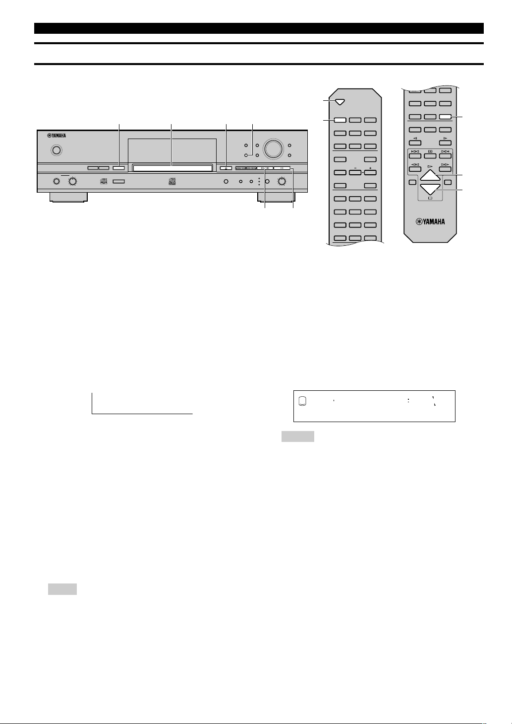
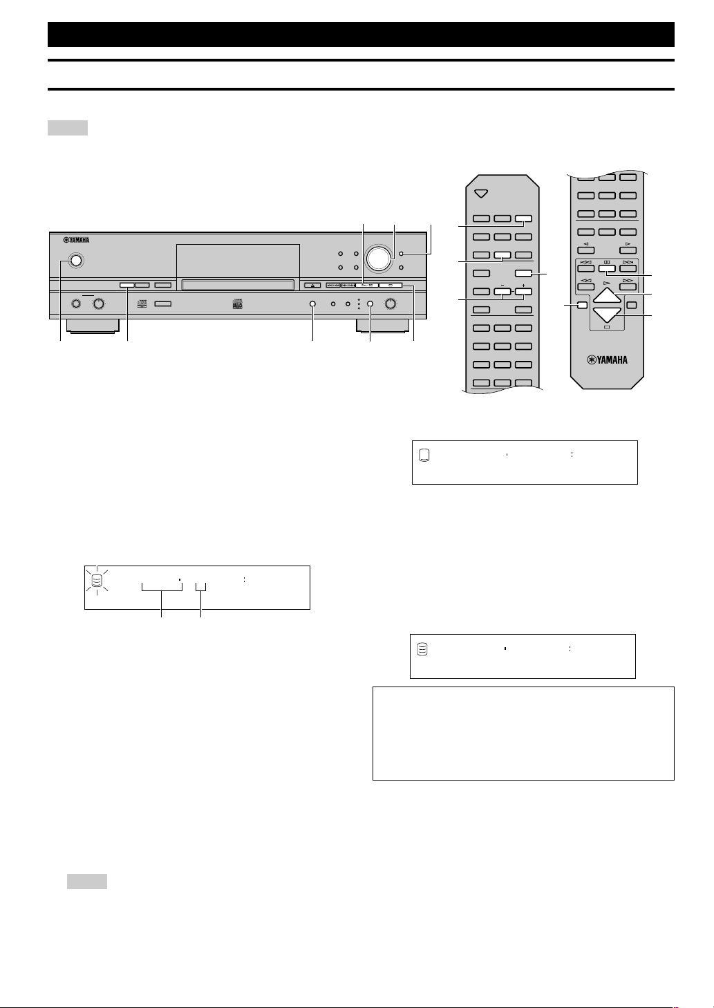
NAMES OF BUTTONS AND CONTROLS ...................... 7
Front Panel ............................................................................. 7
Remote Control ..................................................................... 8
Display ................................................................................. 10
Display Information ............................................................. 11
Rear Panel ............................................................................ 12
CONNECTIONS ............................................................ 12
COPYING AND RECORDING ONTO THE HDD
COPYING FROM A CD ONTO THE HDD ..................... 14
Copying All Tracks on a CD ............................................... 14
Copying Favorite Tracks on the CD .................................... 16
Advanced Operations .......................................................... 17
RECORDING FROM AN EXTERNAL COMPONENT
ONTO THE HDD ........................................................ 20
Recording from the Digital Components ............................ 20
Recording from the Analog Components ............................ 21
Recording Using an External Timer .................................... 22
Adjusting the Recording Level ............................................ 24
Advanced Operations .......................................................... 25
EDITING
EDITING MENU ITEMS ................................................. 29
ALBUM EDITING .......................................................... 30
Album Editing Operation .................................................... 30
TRACK EDITING ........................................................... 39
Track Editing Operation ...................................................... 39
DISC EDITING ............................................................... 52
Disc Editing Operation ........................................................ 52
UNDO FUNCTION ......................................................... 58
BOOKMARK ................................................................. 59
COPYING AND RECORDING ONTO A CD-R OR
CD-RW DISC
COPYING FROM THE HDD ONTO A CD-R OR CD-RW
DISC ........................................................................... 60
Copying a Whole Group (Disc, Album or Bookmark) ........ 60
Copying Favorite Tracks on the HDD ................................. 62
High Quality Copying ......................................................... 63
Advanced Operations .......................................................... 64
RECORDING FROM AN EXTERNAL COMPONENT
ONTO A CD-R OR CD-RW DISC .............................. 67
Advanced Operations .......................................................... 69
FINALIZATION .............................................................. 70
ERASING A CD-RW DISC ............................................ 71
DUPLICATION OF A CD
DUPLICATION OF A CD ............................................... 72
High Quality Duplication .................................................... 74
PLAYBACK
PLAYBACK.................................................................... 76
Playing a CD ........................................................................ 76
Playing Tracks on the HDD................................................. 76
Finding the Desired Passage (Search) ................................. 77
Finding the Desired Group (Group Skip) ............................ 77
Finding the Desired Track (Track Skip) .............................. 78
Selecting Tracks Using On-Screen-Display (OSD) ............ 79
Listening with Headphones ................................................. 79
VARIOUS PLAYBACK .................................................. 80
Finding the Desired Passage by Time (Time Search) .......... 80
Setting the Play Style ........................................................... 80
Single Repeat Play ............................................................... 81
Full Repeat Play .................................................................. 82
Random Play ....................................................................... 82
Intro Play ............................................................................. 83
Bookmark Play .................................................................... 83
APPENDIX
DAC (DIGITAL/ANALOG CONVERTER) MODE .......... 84
HDD UTILITY ................................................................. 85
SYSTEM UTILITY .......................................................... 86
ON-SCREEN DISPLAY (OSD) ...................................... 89
DISPLAY MESSAGES................................................... 90
TROUBLESHOOTING................................................... 92
ABOUT PRODUCT INFORMATIONS ........................... 93
SPECIFICATIONS ......................................................... 94
Page 8
E-2
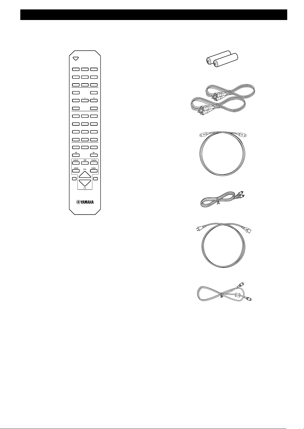
SUPPLIED ACCESSORIES
Make sure the following items are included in your package.
• Remote Control • Batteries (size AA, UM-3, or R6) (2)
OPEN/CLOSE
COPY REC
TEXT/TIME
TRACK NO.
WRITE
MODE MENU
CLEAR
1
ABC2DEF3GHI
4
JKL5MNO6PQR
7
STU8VWX9YZ
SPACE
SYMBOL
0+10
BOOKMARK
REPEAT RANDOM
GROUP SKIP
INTRO
ENTER
COMPLETE
A.M.Q.R.
FINALIZE
INPUT
TIMER REC
ERASE
HDD CDR
• Audio Pin Cables (2)
• Optical Cable
• Video Pin Cable
• Power Cable (for U.S.A. model)
• Coaxial Cable (for U.S.A. model)
Page 9
E-3
English
GETTING STARTED
CD/CD-R/CD-RW COMPATIBLE WITH THIS UNIT
■ Discs that can be used for recording on
this unit
Be sure to use only CD-R and CD-RW discs made by reliable
manufacturers.
CD-R and CD-RW digital audio discs that display either of the
following marks can be used with this unit.
■ Discs that can be used for recording
• CD-R discs can only be recorded on once, and the recorded
material cannot be erased.
• CD-RW discs can be recorded on, have the recorded material
erased, and then recorded on again any number of times.
■ Discs that cannot be used for recording on
this unit
• Discs bearing marks other than those shown above.
• Discs intended for recording computer data.
• Discs intended for professional use or labeled “FOR PROFES-
SIONAL USE ONLY”.
■ 79-minute CD-R disc
The actual recordable time of the CD-R disc with “80” written on
its package is 79 minutes 57 seconds. This manual describes such
CD-R disc as “79-minute CD-R disc”.
■ Finalization of CD-R/CD-RW discs
To play back CD-R discs on a standard CD player and CD-RW
discs on CD-RW-compatible players, you need to perform the
process known as “finalization”. In the finalization process, the
Table of Contents (TOC) is written onto the discs.
Finalized CD-R discs
• CD-R discs can be played on a standard CD player.
• Further recording onto CD-R discs is not possible.
• Some CD players may not play back the finalized CD-R discs
properly due to differences in the playback system of different
manufacturers.
Finalized CD-RW discs
• CD-RW discs cannot be played on a standard CD player. CD-RW
discs can be played back on CD-RW-compatible players such as
this unit.
• Tracks written on CD-RW discs can be erased, and additional
tracks can be recorded after the TOC has been erased.
■ Erasure or loss of data
Yamaha and suppliers accept no liability for the loss of data written
on the HDD and CD-R or CD-RW discs, or any problems caused as
a result of using this unit. As a precaution, it is recommended that
the discs are tested after they have been recorded on. Furthermore,
under no circumstances do Yamaha and suppliers guarantee the
reliability of the discs.
■ Discs that can be played back
In addition to CD-R and CD-RW digital audio discs described
above, commercially available pre-recorded CDs bearing the marks
shown below can also be played on this unit.
Caution
• If you use the CDs that do not meet the CD standards, this unit
may not operate properly.
■ Playback of the CD-R disc copied with the
Audio Master Quality Recording mode
The Audio Master Quality Recording mode enables you to create a
CD with high quality sounds by increasing the linear velocity when
copying. The CD-R discs copied with this mode meet the CD
standards and can be played on a standard CD player. However,
some CD recorders may not play back these CD-R discs properly.
■ Playback on DVD players
Before playing back a finalized CD-R or CD-RW discs on a DVD
player, please check whether the DVD player is compatible with
CD-R or CD-RW discs or not. Refer to the owner’s manual of the
DVD player for more information. CD-R or CD-RW discs cannot
be played on a DVD player that is not compatible with CD-R or
CD-RW discs.
IMPORTANT
• Please check the copyright laws in your country to record from
records, CDs, radio, etc. Recording of copyright material may
infringe copyright laws.
FOR CONSUMER
FOR CONSUMER USE
FOR MUSIC USE ONLY
Page 10
E-4
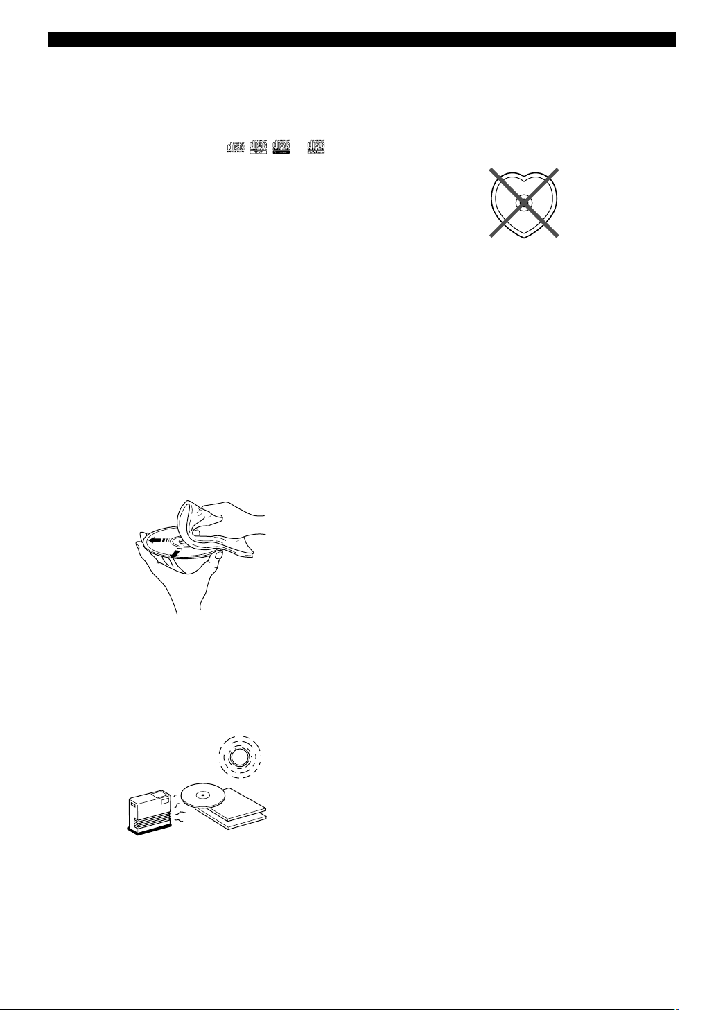
■ Handling of discs
Heed the following notes on handling of discs not to create any
cause for a recording failure, a loss of the recorded data, or a
malfunction of this unit.
• This compact disc recorder is designed for use with CDs
(including 8cm [3”] discs) bearing the
, , , or
marks only. Never attempt to load any other type of disc into this
unit.
• CDs are not subjected to wear during play. However if the disc is
handled improperly, damage may be created on the disc to
adversely affect the disc’s play.
• When writing on the label side of CD-R or CD-RW discs, use an
oil-based felt-tipped pen.
• Do not use cleaning discs or warped discs. All of these could
damage this unit.
• Although playback of CDs is generally not affected by small
particles of dust or fingerprints on their playing surface, dust,
fingerprints, small scratches and direct sunlight on the recording
surface of a CD-R or CD-RW disc may make recording impossible. Therefore, for optimal performance of the recorder and for
long-term enjoyment of your CD collection, handle discs
correctly as outlined in the following guidelines.
1. Hold discs by touching only the edges or center hole.
2. When a disc is not currently being used, remove it from the
recorder and store in an appropriate case.
3. With proper disc maintenance, cleaning should not be
necessary. However, should cleaning be required, wipe by
using a clean, dry cloth. Do not wipe with a circular motion;
wipe straight outward from the center.
• Do not try to clean the disc’s surface by using any type of disc
cleaner, record spray, antistatic spray or liquid, or any other
chemical-based liquid, because such substances might irreparably
damage the disc’s surface.
• Do not expose discs to direct sunlight, high temperature, or high
humidity for a long period of time, because this might warp or
otherwise damage the disc.
■ To prevent a malfunction of this unit
• Do not use any non-standard shaped CDs (heart, flower shaped,
etc.) available on the market, because they are off-balance in their
weight.
If a non-standard shaped CD is loaded into this unit, it may create
problems such as improper playback, opening the disc tray,
creating an usual noise, and this unit’s failure.
• Be sure to use a felt-tip pen or similar writing tool when writing
on the label side of the disc. Do not use a ball-point pen, pencil, or
other hard-tipped writing tool, as these may damage the disc and
may adversely affect further recording on the disc.
• Do not use the discs with glue left on their surface. It may get
stuck in this unit or create damage to this unit.
• When using an 8cm (3”) disc, do not place a normal 12cm (5”)
disc on top of it.
• Do not use the discs printed with commercially available label
printers.
No!
CD/CD-R/CD-RW COMPATIBLE WITH THIS UNIT
Page 11

E-5
English
GETTING STARTED
Rules of Digital Recording
■ SCMS—Serial Copy Management System
As a digital audio component, this unit conforms with the Serial
Copy Management System (SCMS) standards. The Serial Copy
Management System restricts copies made by recording digital
signals to first-generation copies only.
The digital program sources that have been recorded cannot be
digitally recorded again.
There are 2 rules as follows:
Rule 1
Digital sources such as commercially available CDs can be copied
digitally onto other recordable digital media with this unit (a firstgeneration digital copy). However, the first-generation digital copy
cannot be copied digitally any further.
Rule 2
The source that was recorded via the ANALOG LINE IN (REC)
jacks can be copied digitally onto other recordable digital media (a
first-generation digital copy). However, the first-generation digital
copy cannot be copied digitally any further.
This unit monitors the SCMS status for each track when a digital
recording is made. If the track is protected from digital recording
and copying, it is not possible to make a digital recording and copy
of that track.
The SCMS standard does not apply to analog recording and
copying.
When making a copy from a CD onto the HDD, or from the HDD
onto a CD-R or CD-RW disc, any of the copy methods described
below can be selected. The following selections are contained in
“Copy Method”.
•“Auto Dig/Anlg”:
Automatically switches to analog recording if the track cannot be
digitally recorded for SCMS.
•“Digital Copy”:
Performs digital copying of only those tracks that can be digitally
copied.
•“Digital Move”:
Performs digital copying of the tracks that cannot be digitally
copied by “Digital Copy” when copying from the HDD onto a
CD-R or CD-RW disc.
•“Analog Copy”:
Performs analog copying regardless of the SCMS standard.
■ Digital Move
This unit has a built-in HDD with large space that makes a long
recording possible. You can create your own CD by editing the
various program sources that have been recorded onto the HDD of
this unit and copying them onto a CD-R or CD-RW disc.
If you want to make a digital copy of the original data that has been
created on the HDD to a CD-R or CD-RW disc, the “Digital Move”
method is convenient. You can make a digital copy from the HDD
onto a CD-R or CD-RW disc even if the track is protected from
making a second-generation copy by the SCMS standard.
However, since the concept of “Digital Move” is that the data is
moved from the HDD onto a CD-R or CD-RW disc, the original
data on the HDD is erased when moving is complete. See page 65
for details.
RULES OF DIGITAL RECORDING AND NOTES ON SYSTEM
Notes on System
■ Number of recordable discs and tracks and
their length
• One CD-R or CD-RW disc, or one disc on the HDD can be
recorded with up to 99 tracks on them.
• Once 99 tracks have been recorded, no further recording is
possible even if space for recording is available on the disc.
• The minimum length of one track must be 4 seconds. If a
recording is stopped while the track is less than 4 seconds long,
this unit will record for 4 seconds, and then stop recording. The
maximum length of one track is 99 minutes 59 seconds for the
HDD.
• 999 discs can be created at maximum on the HDD of this unit.
However, the number of discs that can be created is limited
according to the space availability (total recordable time) on the
HDD.
• The maximum length of one disc on the HDD is 99 minutes 59
seconds. However, since each track on the HDD is handled in the
unit of frame (75 frames are equal to one second), the maximum
length of one track or disc may vary slightly.
• When recording on a CD-R or CD-RW disc, 2-second silence will
be automatically added to the beginning of the first track.
Therefore the actual total recordable time will be 2 seconds
shorter than the total recordable time of a CD-R or CD-RW disc.
■ Source sampling rate conversion
• Digital input of this unit supports sampling frequencies of 32kHz,
44.1kHz, 48kHz, and 96kHz. This unit converts these inputs to
the 44.1kHz,16-bit digital signals and records them onto the
HDD, or a CD-R or CD-RW disc.
• Analog input is also converted to the same digital signal to be
recorded.
• This unit outputs the signals at the sampling frequency of
44.1kHz, 16-bit from its digital output.
■ Recording of non-audio signals
• This unit is designed exclusively for recording audio signals.
Recording is only possible for audio signals.
• When a CD with CD TEXT is copied onto the HDD, CD TEXT
will be automatically copied if it is not copy protected. When a
CD with CD TEXT is recorded from an external CD player, CD
TEXT cannot be copied even if it is not copy protected. To copy
CD TEXT, use the built-in CDR drive of this unit.
• If the digital signals contain graphic data such as CD graphics, the
non-audio signals will not be recorded.
• It is not possible to record from non-audio sources such as CD-
ROM or DVD.
■ Data processing
• A small amount of space may be used for data processing besides
recording the actual program sources.
• Although this unit is capable of recording 999 albums at
maximum onto the HDD, the data processing speed may slow
down if a large number of albums is created.
Page 12
E-6
RULES OF DIGITAL RECORDING AND NOTES ON SYSTEM
Data on the HDD
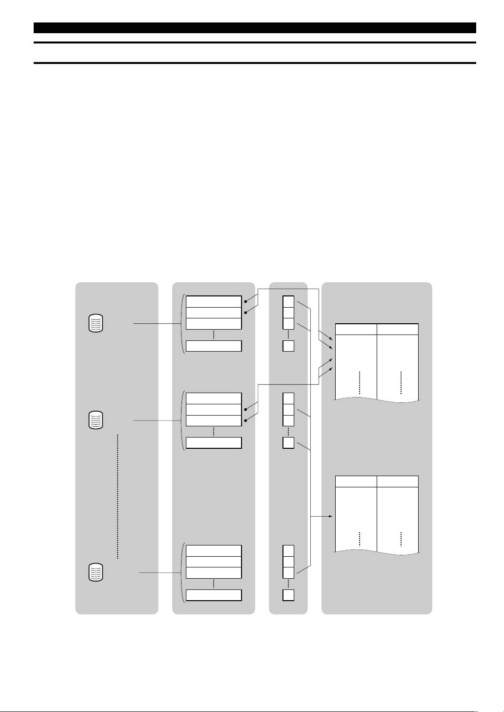
The data recorded onto the built-in HDD of this unit will be numbered and organized based on the following concept:
Disc
One consequent recording is counted and numbered as one unit of
disc. The HDD of this unit can record 999 discs at maximum.
(However, the number of discs to be created may be less than 999
for the space availability on the HDD.) The maximum length of one
disc on the HDD is 99minutes 59 seconds.
Track
99 tracks can be recorded onto a disc at maximum. (However the
number of discs tracks to be recorded may be less than 99 for the
space availability on the HDD.) One track must be 4 seconds at
shortest and 99 minutes 59 seconds at longest.
Album
A group of the source programs selected from different discs and
recorded as the playlist is called “album”. “Album” corresponds to
the “program” function (to play back favorite tracks in the desired
order) of a standard CD player. This unit can record 999 albums at
maximum onto the HDD.
Bookmark
This unit can make a temporary bookmark on a favorite track as
playing back. The list of the program sources marked is called
“bookmark”. This marking is temporary and cannot be duplicated.
However, an album can be easily created by copying the
bookmarked tracks. See page 32 for details.
Group
A collection of disc(s), album(s), and a bookmark are generically
called “group”.
Disc 1
Track 1
Track 2
Track 3
Track 99
✓
✓
Disc 2
Track 1
Track 2
Track 3
Track 99
✓
✓
Disc 999
Track 1
Track 2
Track 3
Track 99
✓
Disc
1
1
2
2
Track
1
2
2
3
Disc
1
2
1
999
2
Track
1
2
3
3
99
Disc Track Bookmark Album
Example of the playlist
Example of the copied tracks
with bookmarks
* The tracks are listed in the
order of copying.
Page 13
E-7
English
GETTING STARTED
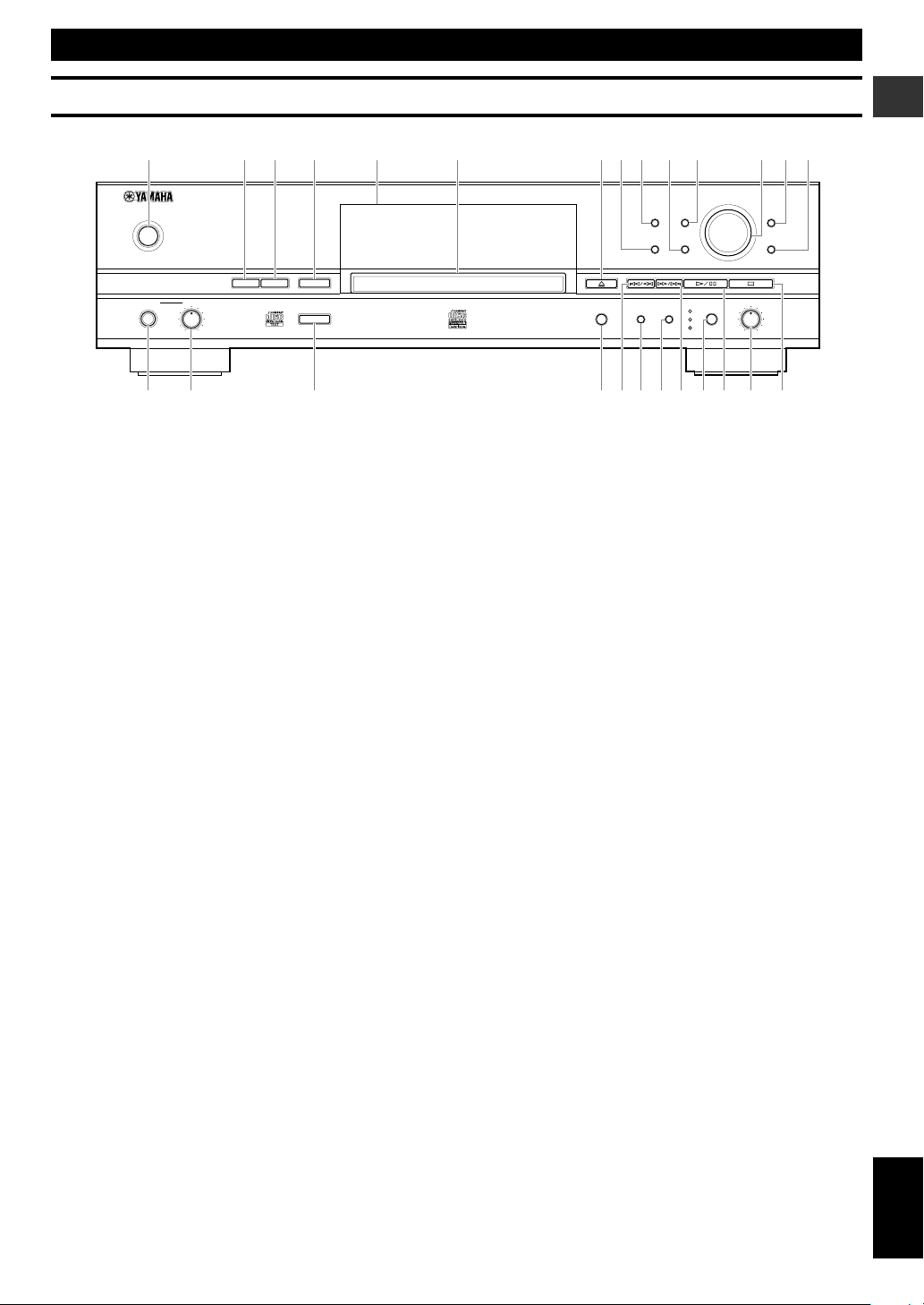
1 POWER
2 HDD
3 CDR
4 COPY
5 Front panel display
6 Disc tray
7 v (Open/Close)
8 TRACK NO./BOOKMARK
9 TEXT/TIME
0 COMPLETE
q MODE
w MULTI JOG knob/DIGITAL REC LEVEL control
e MENU
NAMES OF BUTTONS AND CONTROLS
Front Panel
r CLEAR
t PHONES jack
y PHONES LEVEL control
u A.M.Q.R.
i REC
o t/e (Skip/Search)
p FINALIZE
a ERASE
s r/y (Search/Skip)
d INPUT
f w /d (Play/Pause)
g ANALOG REC LEVEL control
h a (Stop)
NATURAL SOUND HDD/CD RECORDER
TEXT/TIME MODE
MULTI JOG
DIGITAL REC LEVEL
PUSH ENTER
TRACK NO.
FINALIZE ERASE
BOOKMARK
COMPLETE
MENU
CLEAR
MIN MAX
OPTICAL
ANALOG REC LEVEL
INPUT
REC
COAXIAL
ANALOG
COPY
A.M.Q.R.
CDRHDD
MIN MAX
LEVELPHONES
POWER
1
ty uiopasdfgh
23 4 5 6 7890q wer
Page 14
E-8
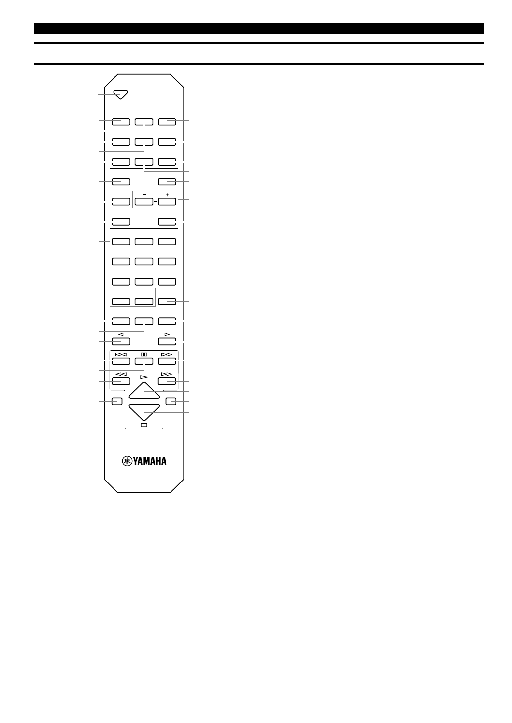
NAMES OF BUTTONS AND CONTROLS
Remote Control
OPEN/CLOSE
COPY REC
TEXT/TIME
TRACK NO.
WRITE
MODE MENU
CLEAR
1
ABC2DEF3GHI
4
JKL5MNO6PQR
7
STU8VWX9YZ
SPACE
SYMBOL
0+10
BOOKMARK
REPEAT RANDOM
GROUP SKIP
INTRO
ENTER
COMPLETE
A.M.Q.R.
FINALIZE
INPUT
TIMER REC
ERASE
HDD CDR
1
2
3
4
5
6
7
8
0
9
q
w
e
r
t
y
u
i
o
p
a
s
d
f
g
h
j
k
l
;
z
x
1 OPEN/CLOSE
2 COPY
3 TIMER REC
4 A.M.Q.R.
5 FINALIZE
6 TEXT/TIME
7 MODE
8 COMPLETE
9 CLEAR
0 Alphabetical/numeric buttons
q REPEAT
w RANDOM
e GROUP SKIP q
r t (Track Skip)
t d (Pause)
y e (Search)
u HDD
i REC
o ERASE
p TRACK NO. WRITE
a INPUT
s MENU
d +/–
f ENTER
g BOOKMARK
h INTRO
j GROUP SKIP w
k y (Track Skip)
l r (Search)
; w (Play)
z CDR
x a (Stop)
Page 15
E-9
English
GETTING STARTED
NATURAL SOUND HDD/CD RECORDER
TEXT/TIME MODE
MULTI JOG
DIGITAL REC LEVEL
PUSH ENTER
TRACK NO.
FINALIZE ERASE
BOOKMARK
COMPLETE
MENU
CLEAR
MIN MAX
OPTICAL
ANALOG REC LEVEL
INPUT
REC
COAXIAL
ANALOG
COPY
A.M.Q.R.
CDRHDD
MIN MAX
LEVELPHONES
POWER
30°
30°
NAMES OF BUTTONS AND CONTROLS
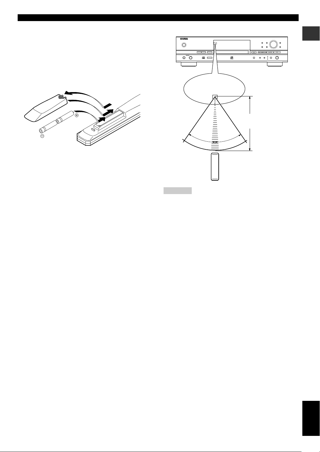
■ Loading the batteries in the remote control
1. Remove the battery compartment cover on the back
of the remote control.
2. Insert 2 batteries (AA, UM-3 or R6 type) according to
the polarity markings on the inside of the battery
compartment.
3. Close the cover until it snaps into place.
■ Battery replacement
If you find that the remote control must be used closer to this unit
than usual, the batteries are weak. Replace both batteries with new
ones.
■ Notes on batteries
• Use only AA, UM-3, or R6 type batteries for replacement.
• Do not mix a new battery with a used one.
• A rechargeable battery cannot be used.
• Do not mix different types of battery.
• Do not attempt to short out the batteries by directly connecting the
plus (+) and the minus (–) with a piece of metal.
• Remove the batteries if the remote control will not be used for an
extended period of time.
• If batteries leak, dispose of them immediately. Clean the battery
compartment thoroughly before installing new batteries.
■ Remote control operation range
Cautions
• If operation of this unit by the remote control creates any
malfunction in any other components, change the placement of
the component.
• Do not spill any liquid on or drop the remote control. Do not
place it near a heater or in the bathroom where the temperature
and humidity become high.
• Make sure the remote control sensor is not exposed to direct
sunlight or strong lights. If it is, it may not function correctly.
Within 6m (20’)
2
1
3
Remote control sensor
Page 16
E-10
NAMES OF BUTTONS AND CONTROLS
1 HDD mark
2 TOTAL indicator
3 DUPLCT indicator
4 A.M.Q.R. indicator
5 Information display
6 CDR mark
7 REC indicator
8 ALBM indicator
9 MARK indicator
0 Playback mode/play style indicator
S indicator
G indicator
A indicator
REP indicator
RNDM indicator
Display
ALBM
MARK
A.M.Q.R. AUTO PRD DIG M
REC
LEVEL
TRACK
TOC GROUP
TIME
CDR W
L
R
dB –30 –10 –6 –2 0
MULTRNDM ALL SYNC ANLG
TOTAL
DUPLCT
S G A REP
8888888888888
8 r9 0
qw
e t y
1
23 4 5
67
q Recording/copying mode indicator
AUTO indicator
PRD indicator
MULT indicator
ALL indicator
SYNC indicator
w Copying method indicator
DIG indicator
M indicator
ANLG indicator
e Level meter
r TOC indicator
t CD-RW indicator
y MULTI JOG status indicator
LEVEL indicator
TRACK indicator
GROUP indicator
TIME indicator
Page 17
E-11
English
GETTING STARTED
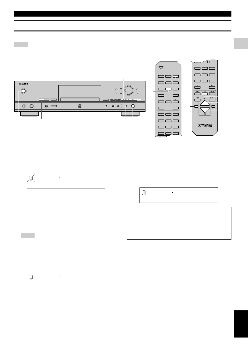
■ Display while playing the data on the HDD
Group number, track number and elapsed time of the
track being played
Group number, track number and remaining time of the
track being played
Group number and group total time
Group number and group remaining time
Group title or track title
Group title
Track title
The group title with the GROUP indicator and the track title with
the TRACK indicator are switched by pressing the MULTI JOG
knob.
■ Display while recording onto the HDD
Disc number, track number and elapsed time of the track
being recorded
Disc number and total recorded time on the disc
NAMES OF BUTTONS AND CONTROLS
Display Information
The display located in the center of this unit provides the information about the drive (HDD or CDR drive) selected.
Each time TEXT/TIME is pressed, the display changes according to the operation.
Dsc001 1 004
GROUP
L
R
dB –30 –10 –6 –20
G
Dsc001 1- 221
GROUP
L
R
dB –30 –10 –6 –20
G
Dsc001 6545
GROUP
L
R
dB –30 –10 –6 –20
TOTAL
G
Dsc001 -6240
GROUP
L
R
dB –30 –10 –6 –20
TOTAL
G
LIVE AT CRANE
GROUP
L
R
dB –30 –10 –6 –20
G
PRIDE AND JOY
TRACK
L
R
dB –30 –10 –6 –20
G
■ Display while playing a CD
Track number and elapsed time of the track being played
Track number and remaining time of the track being
played
Disc total time
Disc remaining time
CD TEXT (when available)
Disc title
Track title
The group title with the GROUP indicator and the track title with
the TRACK indicator are switched by pressing the MULTI JOG
knob.
■ Display while recording onto a CD-R or CD-
RW disc
Track number and elapsed time of the track being
recorded
Total recorded time on a disc
Total recordable time on a disc
Dsc001 1 004
REC
L
R
dB –30 –10 –6 –20
Dsc001 1543
REC
L
R
dB –30 –10 –6 –20
TOTAL
1 004
TOC GROUP
CD
L
R
dB –30 –10 –6 –20
1- 221
TOC GROUP
CD
L
R
dB –30 –10 –6 –20
6545
TOC GROUP
CD
L
R
dB –30 –10 –6 –20
TOTAL
-6240
TOC GROUP
CD
L
R
dB –30 –10 –6 –20
TOTAL
LIVE AT CRANE
TOC GROUP
CD
L
R
dB –30 –10 –6 –20
PRIDE AND JOY
TRACK
TOC
CD
L
R
dB –30 –10 –6 –20
1 004
REC
GROUP
CDRW
L
R
dB –30 –10 –6 –20
1543
REC
GROUP
CDRW
L
R
dB –30 –10 –6 –20
TOTAL
- 221
REC
GROUP
CDRW
L
R
dB –30 –10 –6 –20
TOTAL
Page 18
E-12
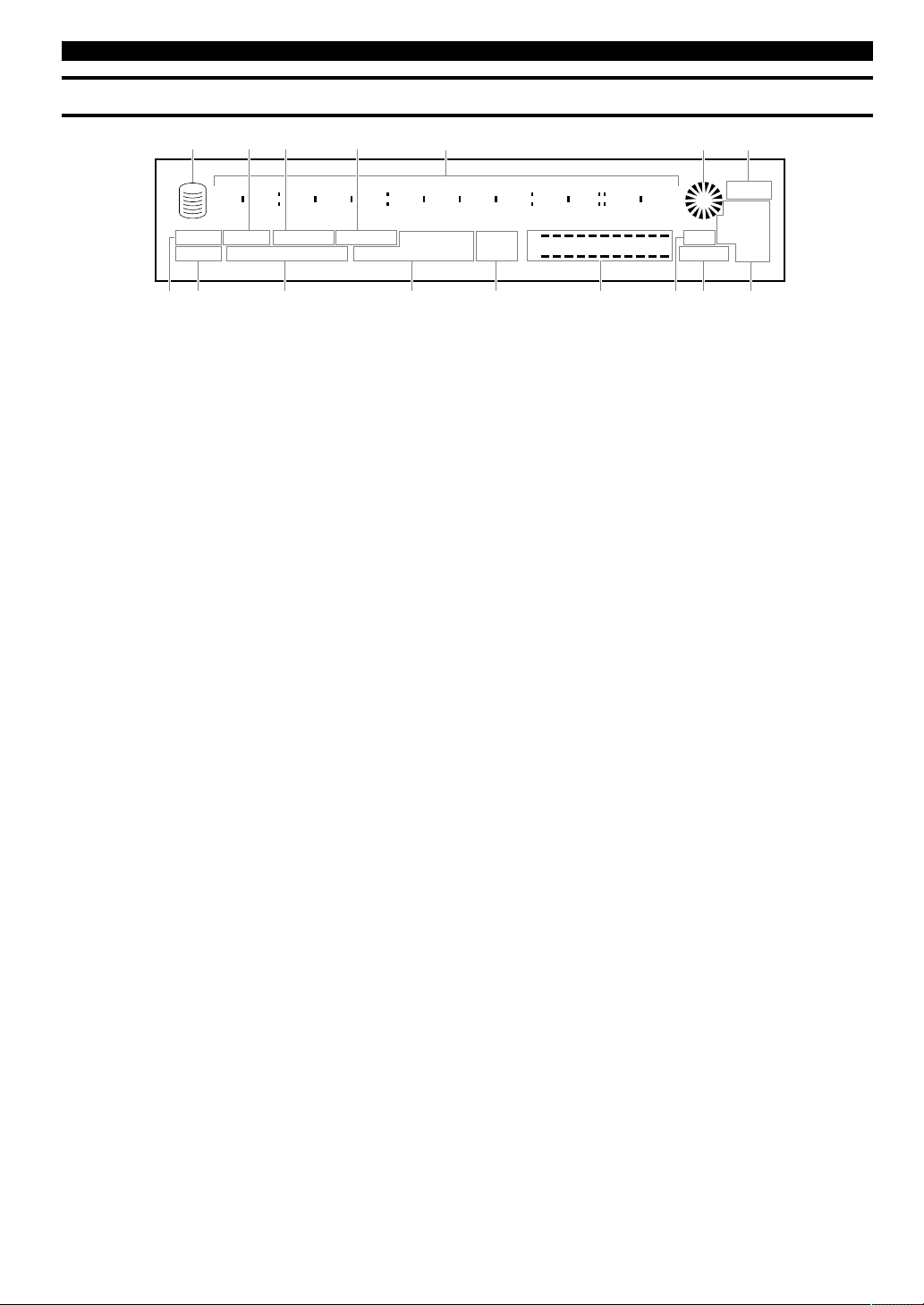
NAMES OF BUTTONS AND CONTROLS
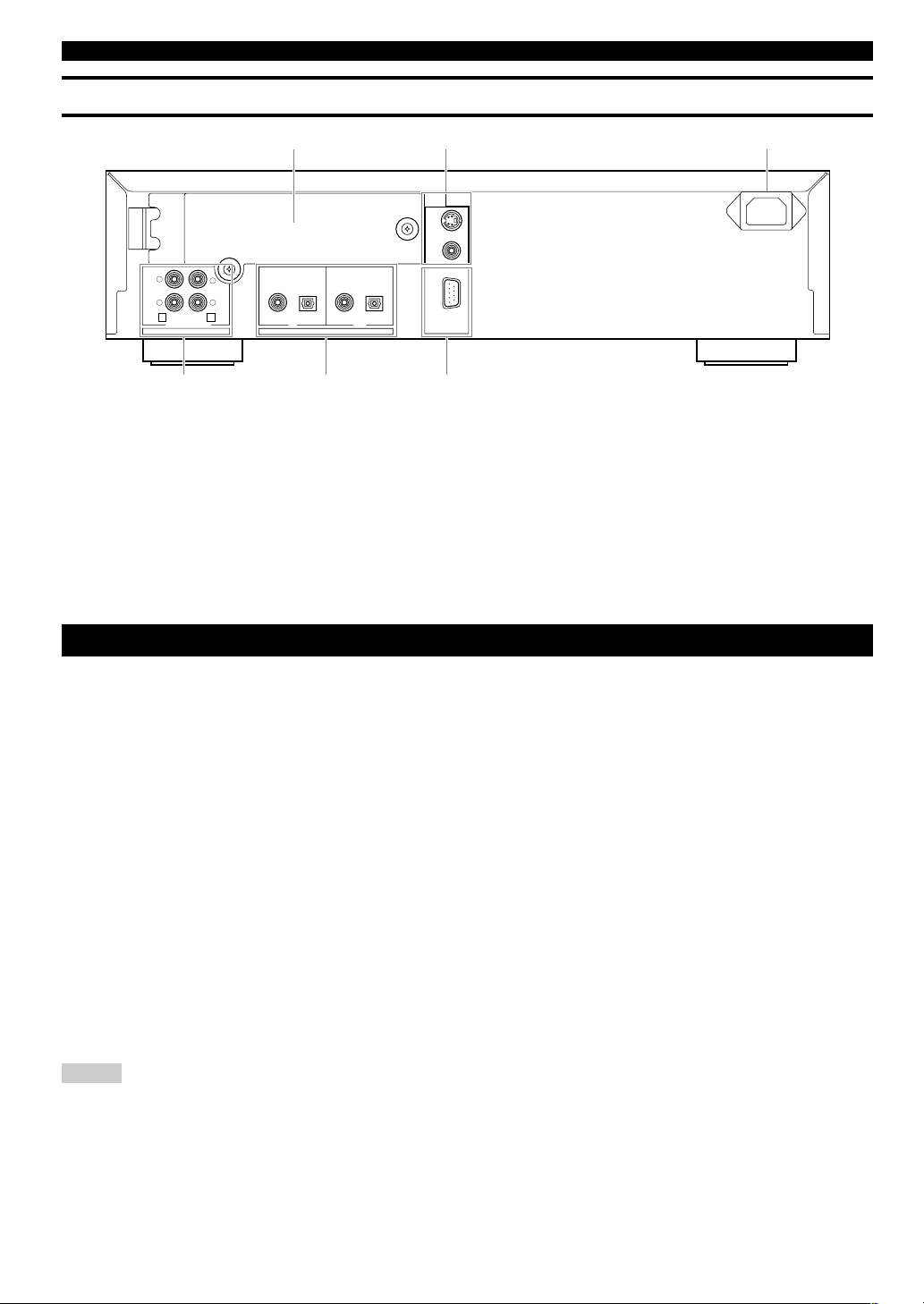
Rear Panel
LINE IN — LINE OUT IN OUT
DIGITAL
REC COAXIAL OPTICAL COAXIAL OPTICAL
RS–232C
VIDEO
VIDEO
OUT
S VIDEO
ANALOG
PLAY
R
L
R
L
4 3
12 3
5 64
CONNECTIONS
Turn off the power of this unit and the other components, and unplug them from the wall outlet before making any connections.
■ Digital connections
• This unit has the DIGITAL OPTICAL jacks and DIGITAL COAXIAL jacks. Connect either the DIGITAL OPTICAL jacks, or the
DIGITAL COAXIAL jacks according to the component to be connected.
• Using the optical fiber cable, connect the DIGITAL IN (OPTICAL) jack on this unit to the digital optical output jack on the other
component, and the DIGITAL OUT (OPTICAL) jack on this unit to the digital optical input jack on the other component.
• When using the DIGITAL IN/OUT (COAXIAL) jacks, make connections with coaxial cables. Connect the DIGITAL IN (COAXIAL) jack
on this unit to the digital coaxial output jack on the other component, and the DIGITAL OUT (COAXIAL) jack on this unit to the digital
coaxial input jack on the other component.
■ Analog connections
• Make sure to connect the L (left) and R (right) input and output jacks on this unit to the correct L (left) and R (right) input and output jacks
on the other component.
• Connect the ANALOG LINE IN (REC) jack on this unit to the analog output jack on the other component, and the ANALOG LINE OUT
(PLAY) jack on this unit to the analog input jack on the other component.
• The ANALOG LINE IN (REC)/LINE OUT (PLAY) jacks on this unit are numbered # and $ respectively. Connect these jacks to the
jacks with the same numbers when connecting this unit to a Yamaha amplifier or receiver.
• To connect the turntable directly to this unit, first connect it to the phono equalizer and then connect to the ANALOG LINE IN (REC)
jacks on this unit.
Notes
• When you play the data on the HDD or CDs, signals are output both from the ANALOG LINE OUT (PLAY) jack and from the DIGITAL
OUT (OPTICAL/COAXIAL) jacks.
• Signals that are output through the DIGITAL OUT (OPTICAL) jacks or the DIGITAL OUT (COAXIAL) jacks while playing the data on
the HDD do not have information about the track markers. Therefore if these signals are recorded by an MD player, the track markers may
not be placed correctly on the recorded MD disc.
1 HDD slot
2 VIDEO OUT jacks
S VIDEO jack
VIDEO jack
3 AC inlet
4 ANALOG jacks
ANALOG LINE IN (REC) jacks
ANALOG LINE OUT (PLAY) jacks
5 DIGITAL jacks
DIGITAL IN (COAXIAL) jack
DIGITAL IN (OPTICAL) jack
DIGITAL OUT (COAXIAL) jack
DIGITAL OUT (OPTICAL) jack
6 RS-232C terminal
(U.S.A. model)
Page 19
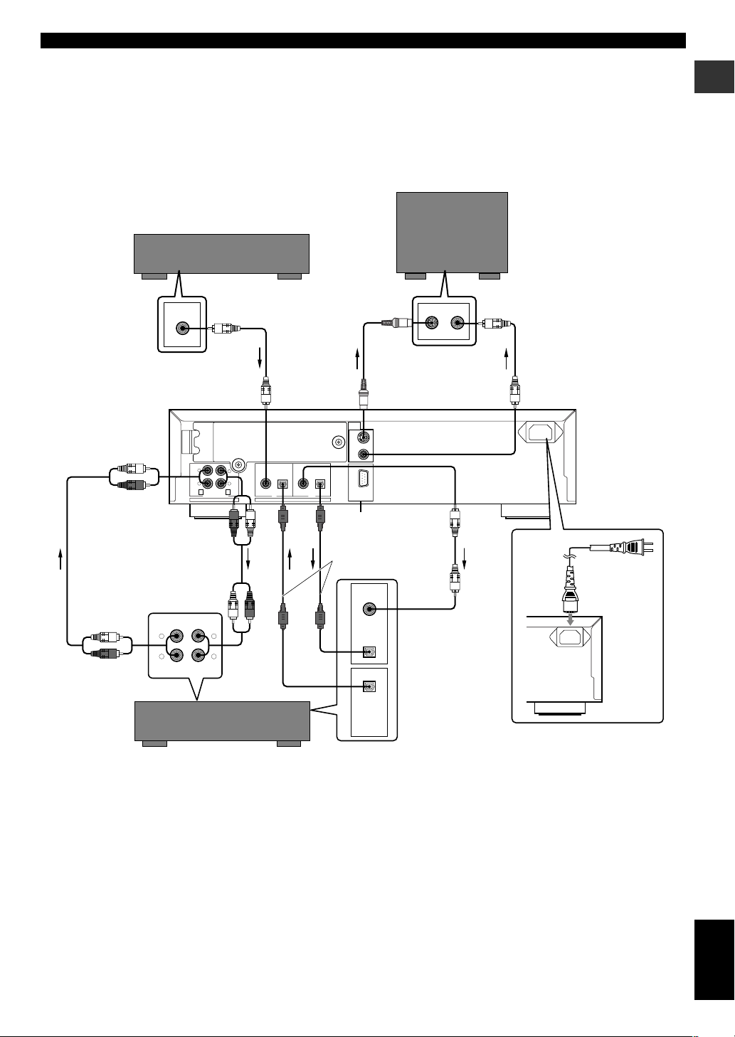
E-13
English
GETTING STARTED
CONNECTIONS
LINE IN — LINE OUT IN OUT
DIGITAL
REC COAXIAL OPTICAL COAXIAL OPTICAL
RS–232C
VIDEO
VIDEO
OUT
S VIDEO
ANALOG
PLAY
R
L
R
L
4 3
REC
PLAY
OUT
IN
DIGITAL
INPUT
COAXIAL
DIGITAL
OUTPUT
R
L
R
L
OPTICAL
OPTICAL
DIGITAL
OUTPUT
COAXIAL
VIDEO IN
S VIDEO
VIDEO
■ Connecting a monitor
• You can display the list of groups or tracks to be played, copying/recording settings or the list of setting items on the monitor by connecting
the monitor to this unit. Connect the S VIDEO jack or the VIDEO jack whichever available on your monitor.
• Use a commercially available S-video cable to connect the S VIDEO jack on this unit and the S-video input jack on the monitor.
• Use an included video pin cable to connect the VIDEO jack on this unit and the composite video jack on the monitor.
• Arrow marks (➞) in the illustration below indicate the direction of the audio signal.
Coaxial cable
(optional)
To wall outlet
DVD player, cable TV tuner, etc
Monitor
S video cable
(optional)
Video pin cable
(included)
*RS-232C terminal
Optical cable
(one included)
**Coaxial cable
Amplifier or receiver
Audio pin cable
(included)
Audio pin cable
(included)
*This terminal is for connection of the personal computer. Information about the connection software is to be
announced on the YAMAHA website (see page 93).
**For U.S.A. model, one coaxial cable with ferrite core is included. Be sure to connect to the DIGITAL OUT
(COAXIAL) jack with this cable, directing the side with ferrite core to this unit.
■ Connecting the power cable
Plug the power cable into the AC inlet when all connections are complete, and then plug in the power cable to the wall outlet.
[Europe, U.K. and Australia models]
Plug in this unit to the wall outlet.
(U.S.A. model)
Page 20
E-14
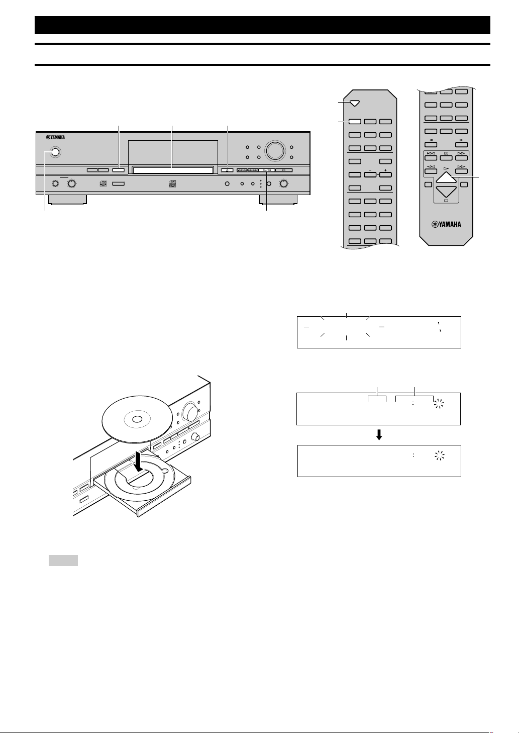
1. Turn on the power of this unit by pressing POWER on
the front panel.
The message “WELCOME TO YAMAHA HDD/CD SYSTEM” appears on the display. After the message is displayed,
this unit is ready for operation.
2. Press v (OPEN/CLOSE on the remote control) to
open the disc tray.
3. Load the CD to copy from on the disc tray.
Place a CD correctly aligned in the recessed area of the disc
tray with its label side facing up.
4. Press v (OPEN/CLOSE on the remote control) to
close the disc tray.
Note
• The disc tray can be also closed by pressing the front edge of
the disc tray gently. If the disc tray is closed in this way, this
unit starts playback of a CD. Press a to stop playback.
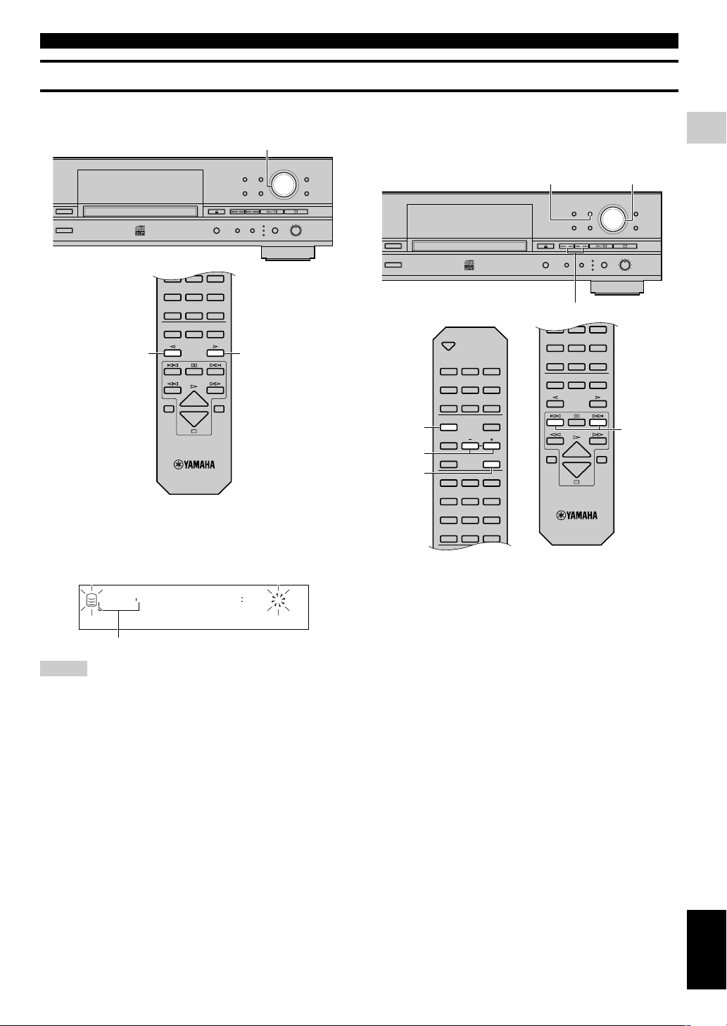
COPYING FROM A CD ONTO THE HDD
Copying All Tracks on a CD
You can copy all tracks on a CD onto the HDD.
NATURAL SOUND HDD/CD RECORDER
TEXT/TIME MODE
MULTI JOG
DIGITAL REC LEVEL
PUSH ENTER
TRACK NO.
FINALIZE ERASE
BOOKMARK
COMPLETE
MENU
CLEAR
MIN MAX
OPTICAL
ANALOG REC LEVEL
INPUT
REC
COAXIAL
ANALOG
COPY
A.M.Q.R.
CDRHDD
MIN MAX
LEVELPHONES
POWER
2,4
6
3
1
5
OPEN/CLOSE
COPY REC
TEXT/TIME
TRACK NO.
WRITE
MODE MENU
CLEAR
1
ABC2DEF3GHI
4
JKL5MNO6PQR
7
STU8VWX9YZ
SPACE
SYMBOL
0 +10
BOOKMARK
ENTER
COMPLETE
A.M.Q.R.
FINALIZE
INPUT
TIMER REC
ERASE
4
JKL5MNO6PQR
7
STU8VWX9YZ
SPACE
SYMBOL
0 +10
BOOKMARK
REPEAT RANDOM
GROUP SKIP
INTRO
HDD CDR
2,4
5
6
This unit starts reading the information (type and capacity of
the CD) when the CD is loaded. It takes approximately 10 to 15
seconds to complete the reading.
The following message appears on the display during the
reading.
When reading the information has been completed, the display
changes as follows, and this unit becomes ready for operation.
L
R
dB –30 –10 –6 –20
Reading
14 6817
TOC GROUP
CD
L
R
dB –30 –10 –6 –20
1
TOC GROUP
CD
L
R
dB –30 –10 –6 –20
Total number of tracks Total time
Page 21
E-15
English
COPYING AND RECORDING ONTO THE HDD
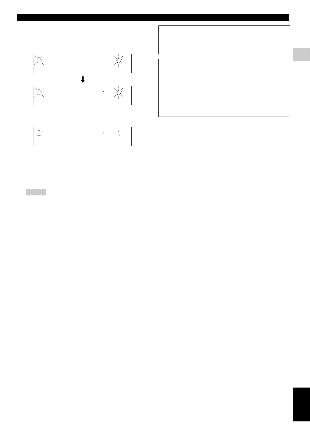
5. Press COPY once.
The following message appears on the display, and this unit
enters the copy standby mode. Copying has not been started yet
at this stage.
6. Start copying.
Press w/d (w on the remote control) to start copying.
The copying conditions (initial settings) are as follows:
• Copy Method: “Digital Copy”
• Copy Level: 0dB
• Copy Speed: “Best Effort”
To change the settings, see “Copying menu setting” on page 18.
Notes
• It takes a few seconds for this unit to become ready to start
copying after w/d (w on the remote control) has been
pressed.
• This unit may create some vibration and rotation noise while
performing the copying process by rotating a CD at high
speed. If this problem occurs, lower the copying speed to
decrease the vibration and rotation noise. (See “Copy Speed”
on page 19.)
To cancel copying, press a.
When copying has been completed, the operation of
the HDD and the CD automatically stops.
HDD π CD-RW
DIG
REC
TOC GROUP
CD
L
R
dB –30 –10 –6 –20
ALL SYNC
003 1 π 1 000
DIG
REC
TOC GROUP
CD
L
R
dB –30 –10 –6 –20
ALL SYNC
003 1 π 1 001
DIG
REC
TOC GROUP
CD
L
R
dB –30 –10 –6 –20
ALL SYNC
CD TEXT
If the CD to be copied contains CD TEXT that can be copied,
CD TEXT is automatically copied when the CD is copied onto
the HDD.
Output of the signals during copying
• During copying at 1x speed, signals are output both from the
ANALOG LINE OUT (PLAY) jack and from the DIGITAL
OUTPUT (OPTICAL/COAXIAL) jacks.
• During copying at 2x speed, signals are output only from the
ANALOG LINE OUT (PLAY) jack.
• During copying at 4x or more speed, signals are output neither
from the ANALOG LINE OUT (PLAY) jack nor the
DIGITAL OUTPUT (OPTICAL/COAXIAL) jacks.
COPYING FROM A CD ONTO THE HDD
Page 22
E-16
COPYING FROM A CD ONTO THE HDD
Copying Favorite Tracks on the CD
You can copy your favorite tracks on a CD onto the HDD.
NATURAL SOUND HDD/CD RECORDER
TEXT/TIME MODE
MULTI JOG
DIGITAL REC LEVEL
PUSH ENTER
TRACK NO.
FINALIZE ERASE
BOOKMARK
COMPLETE
MENU
CLEAR
MIN MAX
OPTICAL
ANALOG REC LEVEL
INPUT
REC
COAXIAL
ANALOG
COPY
A.M.Q.R.
CDRHDD
MIN MAX
LEVELPHONES
POWER
2,7 4
1
1 3,65
OPEN/CLOSE
COPY REC
TEXT/TIME
TRACK NO.
WRITE
MODE MENU
CLEAR
1
ABC2DEF3GHI
4
JKL5MNO6PQR
7
STU8VWX9YZ
SPACE
SYMBOL
0 +10
BOOKMARK
ENTER
COMPLETE
A.M.Q.R.
FINALIZE
INPUT
TIMER REC
ERASE
4
JKL5MNO6PQR
7
STU8VWX9YZ
SPACE
SYMBOL
0 +10
BOOKMARK
REPEAT RANDOM
GROUP SKIP
INTRO
HDD CDR
5
1
2,7
4
3,6
1. Load the CD to copy from on the disc tray.
Press v (OPEN/CLOSE on the remote control) to open the
disc tray, and place a CD with its label side facing up. Then
press v (OPEN/CLOSE on the remote control) to close the
disc tray.
2. Start playback of the CD.
Press w/d (w on the remote control) to start playback.
Playback is started from the beginning of the first track.
3.Press TRACK NO./BOOKMARK (BOOKMARK on the
remote control) while your favorite track is being
played.
The MARK indicator lights on the display.
Press t/e or r/y (t or y on the remote control) to
skip tracks, and repeat above operation.
To cancel a bookmark
Press TRACK NO./BOOKMARK (BOOKMARK on the
remote control) to cancel the bookmark during playback of the
track. The MARK indicator turns off on the display.
4. When the bookmark have been placed to all favorite
tracks, press a to stop playback.
Tracks are listed and stored in order that the bookmarks have
been placed.
To cancel all bookmarks
Press CLEAR as pressing TRACK NO./BOOKMARK on the
front panel while this unit is in the stop mode. “Bookmark Clr”
appears on the display, and all bookmarks are canceled.
Note
• The bookmark placed to the track on the CD will be canceled
if the disc tray is open, or the power of this unit is turned off.
MARK
5. Press COPY once.
This unit enters the copy standby mode. Copying has not been
started yet at this stage.
6. Press TRACK NO./BOOKMARK (BOOKMARK on the
remote control).
The list of the track that the bookmark is placed to is selected
as the group to be copied (the MARK indicator lights on the
display). Press TRACK NO./BOOKMARK (BOOKMARK
on the remote control) again to return to the normal copy
standby mode.
7. Start copying.
Press w/d (w on the remote control) to start copying.
Notes
• It takes a few seconds for this unit to become ready to start
copying after w/d (w on the remote control) has been
pressed.
• This unit may create some vibration and rotation noise while
performing the copying process by rotating a CD at high
speed. If this problem occurs, lower the copying speed to
decrease the vibration and rotation noise. (See “Copy Speed”
on page 19.)
To cancel copying, press a.
When copying has been completed, the operation of
the HDD and the CD automatically stops.
003 1 π 1 001
MARK
DIG
REC
TOC GROUP
CD
L
R
dB –30 –10 –6 –20
ALL SYNC
Page 23
E-17
English
COPYING AND RECORDING ONTO THE HDD
COPYING FROM A CD ONTO THE HDD
Advanced Operations
■ Making an additional copying onto an
already recorded disc
When the copying onto the HDD, you can select the disc on the
HDD to make copy on. Rotate the MULTI JOG knob (press
GROUP SKIP q/GROUP SKIP w on the remote control) to
select the disc number to make the copy on while this unit is in the
copy standby mode.
Notes
• If the disc number is not selected, copying will be made on the
disc with the smallest number available on the HDD.
• When a disc number with recorded tracks is selected, new
recordings will be added to the end of the last track that has been
previously recorded.
Disc number to make the copy on
ER
TEXT/TIME MODE
MULTI JOG
DIGITAL REC LEVEL
PUSH ENTER
TRACK NO.
FINALIZE ERASE
BOOKMARK
COMPLETE
MENU
CLEAR
MIN MAX
OPTICAL
ANALOG REC LEVEL
INPUT
REC
COAXIAL
ANALOG
COPY
A.M.Q.R.
MULTI JOG
4
JKL5MNO6PQR
7
STU8VWX9YZ
SPACE
SYMBOL
0 +10
BOOKMARK
REPEAT RANDOM
GROUP SKIP
INTRO
HDD CDR
GROUP SKIP wGROUP SKIP q
003 1 π 1 000
DIG
REC
TOC GROUP
CD
L
R
dB –30 –10 –6 –20
ALL SYNC
■ Setting the copying mode
This unit provides various copying modes. Choose the one that suits
your needs.
Initial setting: All Synchro
1. Press MODE while this unit is in the copy standby
mode.
You can select the copying mode.
2. Rotate the MULTI JOG knob (press +/– on the remote
control) to select the copying mode.
Choose one of the modes listed below.
All Synchro (All-synchronized copying mode)
This mode copies all of the material from a single audio source
at the same time as the source programs are being played.
Track markers are automatically placed between the tracks
being recorded.
Multi Synchro (Multi-synchronized copying mode)
This mode copies the set number of tracks at the same time as
the source programs are being played. The number of tracks to
be recorded can be set in the range of 1 to 99 tracks. This mode
is convenient to record a mix of tracks from different sources.
ER
TEXT/TIME MODE
MULTI JOG
DIGITAL REC LEVEL
PUSH ENTER
TRACK NO.
FINALIZE ERASE
BOOKMARK
COMPLETE
MENU
CLEAR
MIN MAX
OPTICAL
ANALOG REC LEVEL
INPUT
REC
COAXIAL
ANALOG
COPY
A.M.Q.R.
t/e, r/y
MULTI JOGMODE
OPEN/CLOSE
COPY REC
TEXT/TIME
TRACK NO.
WRITE
MODE MENU
CLEAR
1
ABC2DEF3GHI
4
JKL5MNO6PQR
7
STU8VWX9YZ
SPACE
SYMBOL
0+10
BOOKMARK
ENTER
COMPLETE
A.M.Q.R.
FINALIZE
INPUT
TIMER REC
ERASE
4
JKL5MNO6PQR
7
STU8VWX9YZ
SPACE
SYMBOL
0+10
BOOKMARK
REPEAT RANDOM
GROUP SKIP
INTRO
HDD CDR
t, y
+, –
ENTER
MODE
Page 24
E-18
3. Press the MULTI JOG knob (ENTER on the remote
control) to confirm the copying mode selected.
If “All Synchro” is confirmed, this unit returns to the copy
standby mode.
If “Multi Synchro” is confirmed, the following message
appears on the display. Go to step 4.
4. Select the number of tracks by rotating the MULTI
JOG knob (pressing +/– on the remote control).
The number can be selected in the 1 to 99 tracks range.
5. Press the MULTI JOG knob (ENTER on the remote
control) to confirm the number selected.
This unit returns to the copy standby mode.
6. Select the track to start copy from by pressing t/e
or r/y (t or y on the remote control).
How many ?1
DIG
REC
TOC
CD
L
R
dB –30 –10 –6 –20
MULT SYNC
■ Copying menu setting
You can make detailed settings on the menu for your copying.
Follow the steps described below for menu setting.
1. Press MENU while this unit is in the copy standby
mode.
You can start setting the copying menu.
2. Select the menu item to be set by rotating the MULTI
JOG knob (pressing +/– on the remote control).
The copying menu contains 3 items as follows:
• Copy Method (setting the copying method)
• Copy Level (setting the copying level)
• Copy Speed (setting the copying speed)
3. Press the MULTI JOG knob (ENTER on the remote
control) to confirm the menu item to be adjusted.
4. Adjust the parameter for each item by rotating the
MULTI JOG knob (pressing +/– on the remote
control).
See the further steps for detailed instructions on parameter
adjustment for each item.
5. Press the MULTI JOG knob (ENTER on the remote
control) to confirm the setting when adjustment has
been completed.
6. Press MENU to close the menu.
This unit returns to the copy standby mode.
ER
TEXT/TIME MODE
MULTI JOG
DIGITAL REC LEVEL
PUSH ENTER
TRACK NO.
FINALIZE ERASE
BOOKMARK
COMPLETE
MENU
CLEAR
MIN MAX
OPTICAL
ANALOG REC LEVEL
INPUT
REC
COAXIAL
ANALOG
COPY
A.M.Q.R.
MULTI JOG MENU
OPEN/CLOSE
COPY REC
TEXT/TIME
TRACK NO.
WRITE
MODE MENU
CLEAR
1
ABC2DEF3GHI
ENTER
COMPLETE
A.M.Q.R.
FINALIZE
INPUT
TIMER REC
ERASE
MENU
+, –
ENTER
COPYING FROM A CD ONTO THE HDD
Page 25
E-19
English
COPYING AND RECORDING ONTO THE HDD
■ Copy Method
Setting of the copying method. Copying may fail if the setting for
“Copy Method” is not correctly made.
Initial setting: Digital Copy
Digital Copy
This method always makes digital copies. Copying is not possible if
the tracks are copy protected by the SCMS standard (see page 5).
Auto Dig/Anlg
Digital and analog copying are automatically switched depending
on the track. If digital copying is prohibited by the SCMS standard
(see page 5), an analog copy is made. For those tracks that can be
digitally copied, a digital copy is made.
Analog Copy
This method always makes analog copies.
Notes
• In analog copying, the data may be copied at a lower sound level.
• The setting is stored in the memory and applies to future copying.
■ Copy Level
Setting of the sound level for copying. Sound level adjustment is
not normally necessary. However it is possible to adjust the copying
sound level to suit you needs.
The following message appears on the display when “Copy Level”
setting is confirmed in step 3 for “Copying menu setting” on page
18.
1. Adjust the copying sound level by rotating the MULTI
JOG knob (pressing +/– on the remote control).
Adjustment is possible in the –12dB to +12dB range by 0.4dB
steps.
Copy Method
DIG
REC
TOC
CD
L
R
dB –30 –10 –6 –20
ALL SYNC
Copy Level
DIG
REC
TOC
CD
L
R
dB –30 –10 –6 –20
ALL SYNC
Level 0.0dB
DIG
REC
LEVEL
TOC
CD
L
R
dB –30 –10 –6 –20
ALL SYNC
2. Press the MULTI JOG knob (ENTER on the remote
control) to confirm the copying level setting.
Notes
• Level adjustment is not possible during copying.
• If the red part on the peak level meter lights at the loudest sound
levels, stop copying to adjust the copying level, and then resume
copying.
• If the level is adjusted, copying is made at maximum 2x speed.
■ Copy Speed
Setting of the copying speed.
Initial setting: Best Effort
Best Effort
Copying is made at the maximum speed possible depending on the
“Copy Method” and “Copy Level” settings.
• When “Digital Copy” is selected: maximum 10x speed
• When “Auto Dig/Anlg” is selected: maximum 2x speed
• When “Analog Copy” is selected: maximum 2x speed
1x Copy
Copying is always made at 1x speed despite the “Copy Method”
and “Copy Level” settings.
2x Copy
Copying is always made at 2x speed despite the “Copy Method”
and “Copy Level” settings.
Notes
• If there are scratches or dust on the CD, the copy speed may drop
automatically even when “Best Effort” is selected.
• The setting is stored in the memory and applies to future copying.
TOC
CD
L
R
dB –30 –10 –6 –20
Copy Speed
DIG
REC
TOC
CD
L
R
dB –30 –10 –6 –20
ALL SYNC
COPYING FROM A CD ONTO THE HDD
Page 26
E-20
RECORDING FROM AN EXTERNAL COMPONENT ONTO THE HDD
Recording from the Digital Components
You can make recordings from the component such as a cable TV tuner and a DVD player digitally connected to this unit.
Note
• Recording onto the HDD is made in the unit called “disc”. The maximum length of one disc on the HDD is 99 minutes 59 seconds. If the
recording has been made exceeding the maximum length, the recording will be made continuously to the next available disc.
NATURAL SOUND HDD/CD RECORDER
TEXT/TIME MODE
MULTI JOG
DIGITAL REC LEVEL
PUSH ENTER
TRACK NO.
FINALIZE ERASE
BOOKMARK
COMPLETE
MENU
CLEAR
MIN MAX
OPTICAL
ANALOG REC LEVEL
INPUT
REC
COAXIAL
ANALOG
COPY
A.M.Q.R.
CDRHDD
MIN MAX
LEVELPHONES
POWER
65 5
4832
1
OPEN/CLOSE
COPY REC
TEXT/TIME
TRACK NO.
WRITE
MODE MENU
CLEAR
1
ABC2DEF3GHI
4
JKL5MNO6PQR
7
STU8VWX9YZ
SPACE
SYMBOL
0 +10
BOOKMARK
ENTER
COMPLETE
A.M.Q.R.
FINALIZE
INPUT
TIMER REC
ERASE
4
JKL5MNO6PQR
7
STU8VWX9YZ
SPACE
SYMBOL
0 +10
BOOKMARK
REPEAT RANDOM
GROUP SKIP
INTRO
HDD CDR
5
4
5
3
2
6
8
6
1. Turn on the power of this unit by pressing POWER on
the front panel.
The message “WELCOME TO YAMAHA HDD/CD SYSTEM” appears on the display. After the message is displayed,
this unit is ready for operation.
2. Press HDD to select the HDD.
3. Press REC.
The HDD mark flashes, and the disc and track numbers to be
recorded are indicated on the display. Recording has not been
started yet at this stage. (Recording pause mode)
4. Select the input source to be recorded.
Press INPUT repeatedly until the OPTICAL or COAXIAL
indicator lights up.
5. Adjust the recording level.
The adjustment of the digital recording level is not normally
necessary. However it is possible to adjust the recording level
to suit your needs.
Play the loudest passage (highest sound level) of the source to
be recorded.
By pressing MENU, the display changes for the level
adjustment.
Rotate the MULTI JOG knob (press +/– on the remote control)
to adjust the recording level. When the adjustment is completed, press MULTI JOG knob (ENTER on the remote
control) to confirm the adjusted recording level.
Note
• Adjust the recording level so that the red part on the peak
level meter does not light at the loudest sound levels.
See “Adjusting the Recording Level” on page 24 for details.
6. Start recording.
Press w/d (w or d on the remote control) to start recording.
7. Start playing the source.
Press w/d (d on the remote control) to stop recording
temporarily. The HDD mark flashes and the track number is
advanced to the next.
Press w/d (w or d on the remote control) to resume recording.
8. Press a to stop recording.
The first track number of the disc at which recording has been
stopped is indicated on the display.
IMPORTANT
• Never turn off the power of this unit during recording.
Recording may not be correctly made, or the data on the HDD
may be damaged.
• During recording, make sure that this unit is not subjected to
shock or vibration as the HDD may be damaged.
Disc number to be recorded Track number to be recorded
Dsc002 1 000
REC
GROUP
L
R
dB –30 –10 –6 –20
SYNC
Dsc002 1 001
REC
L
R
dB –30 –10 –6 –20
SYNC
Dsc002 1
GROUP
L
R
dB –30 –10 –6 –20
G
Page 27
E-21
English
COPYING AND RECORDING ONTO THE HDD
RECORDING FROM AN EXTERNAL COMPONENT ONTO THE HDD
Recording from the Analog Components
You can make recordings from the component such as a cassette deck and a turntable connected to this unit.
Note
• Recording onto the HDD is made in the unit called “disc”. The maximum length of one disc on the HDD is 99 minutes 59 seconds. If the
recording has been made exceeding the maximum length, the recording will be made continuously to the next available disc.
NATURAL SOUND HDD/CD RECORDER
TEXT/TIME MODE
MULTI JOG
DIGITAL REC LEVEL
PUSH ENTER
TRACK NO.
FINALIZE ERASE
BOOKMARK
COMPLETE
MENU
CLEAR
MIN MAX
OPTICAL
ANALOG REC LEVEL
INPUT
REC
COAXIAL
ANALOG
COPY
A.M.Q.R.
CDRHDD
MIN MAX
LEVELPHONES
POWER
6
4
58321
OPEN/CLOSE
COPY REC
TEXT/TIME
TRACK NO.
WRITE
MODE MENU
CLEAR
1
ABC2DEF3GHI
4
JKL5MNO6PQR
7
STU8VWX9YZ
SPACE
SYMBOL
0 +10
BOOKMARK
ENTER
COMPLETE
A.M.Q.R.
FINALIZE
INPUT
TIMER REC
ERASE
4
JKL5MNO6PQR
7
STU8VWX9YZ
SPACE
SYMBOL
0 +10
BOOKMARK
REPEAT RANDOM
GROUP SKIP
INTRO
HDD CDR
4
3
6
8
2
6
1. Turn on the power of this unit by pressing POWER on
the front panel.
2. Press HDD to select the HDD.
3. Press REC.
This unit enters the recording pause mode.
4. Select the input source to be recorded.
Press INPUT repeatedly until the ANALOG indicator lights
up.
5. Adjust the recording level.
Play the loudest passage (highest sound level) of the source to
be recorded, and rotate the ANALOG REC LEVEL control to
adjust the recording level.
Note
• Adjust the recording level so that the red part on the peak
level meter does not light at the loudest sound levels.
See “Adjusting the Recording Level” on page 24 for details.
6. Start recording.
Press w/d (w or d on the remote control) to start recording.
7. Start playing the source.
Press w/d (d on the remote control) to stop recording
temporarily. The HDD mark flashes and the track number is
advanced to the next.
Press w/d (w or d on the remote control) to resume recording.
8. Press a to stop recording.
The first track number of the disc at which recording has been
stopped is indicated on the display.
IMPORTANT
• Never turn off the power of this unit during recording.
Recording may not be correctly made, or the data on the HDD
may be damaged.
• During recording, make sure that this unit is not subjected to
shock or vibration as the HDD may be damaged.
Dsc002 1 000
REC
GROUP
L
R
dB –30 –10 –6 –20
SYNC
Dsc002 1 001
REC
L
R
dB –30 –10 –6 –20
SYNC
Dsc002 1
GROUP
L
R
dB –30 –10 –6 –20
G
Page 28
E-22
RECORDING FROM AN EXTERNAL COMPONENT ONTO THE HDD
Recording Using an External Timer
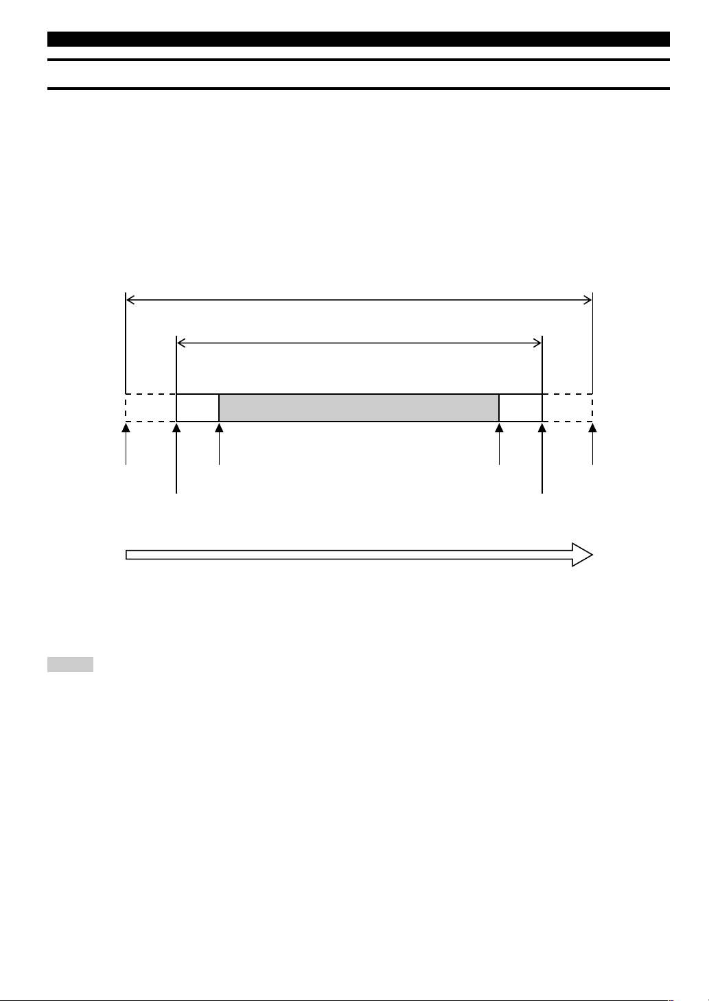
■ Notes on recording time setting
• This unit is not equipped with the clock function. Use an external timer when making a timer recording.
• It may take 30 seconds to 1 minute after the power of this unit is turned on by an external timer until an actual recording starts. (This length
of time is subject to change depending on the condition.) During this time, no recording is made. Therefore set the time that is 2-minute
earlier than the starting time of the program to be recorded for turning on this unit.
• As a characteristic of an HDD recorder, it is necessary to store information to control audio data as well as audio data itself. This information is normally recorded when recording is stopped. Therefore if the power of this unit is turned off before recording is stopped, no
information to control audio data and no audio data are stored. Set the time that is longer than 3-minute after the program to be recorded
finishes for turning off this unit by an external timer.
• Set the time that is 2-minute longer than actual recording time for the total recording time.
Following chart indicates the time flow when this unit makes timer recordings.
Example: To record the program that starts at 9:00 and ends at 10:00.
• Set the external timer to be turned on at 8:58.
• Set the external timer to be turned off after 10:03.
• Set 1 hour 2 minutes for the total recording time on this unit.
Notes
• Actual recorded material includes a little more than the set amount of time at both beginning and end of the recording. Delete unnecessary
parts using the editing operation.
• Recording will be stopped if copy protected digital signals are input while timer recording is being made.
• If you set the total recording time over 99 minutes 59 seconds, recording will be made extending several discs. To play the recorded
materials sequentially, select “Style All” as the play style. See “Setting the Play Style” on page 80.
See next page for the setting procedure.
Time to be set on the external timer
(2 minutes + recording time + 3 minutes or longer)
Recording time to be set on the CDR-HD1300
(Recording time + 2 minutes)
Recording time
Program starting time
CDR-HD1300 starts recording
(30 seconds to 1 minute after the
external timer turns on.)
External timer turns on
External timer turns off
Time flow
Program ending time
CDR-HD1300 finishes
recording
Page 29
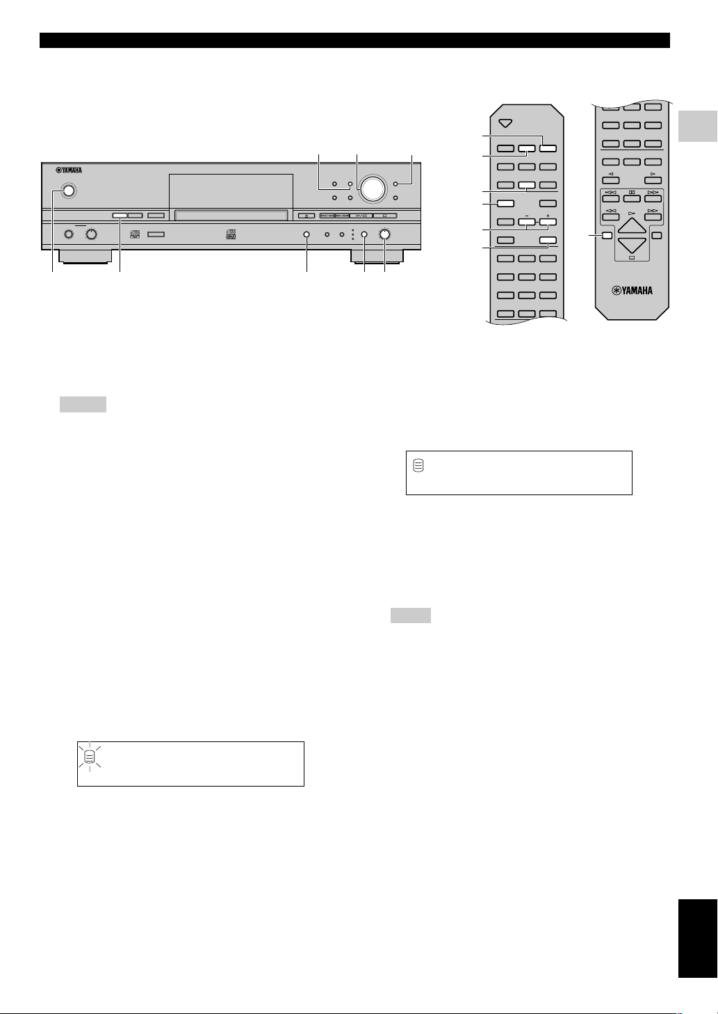
E-23
English
COPYING AND RECORDING ONTO THE HDD
RECORDING FROM AN EXTERNAL COMPONENT ONTO THE HDD
■ Setting for a timer recording
NATURAL SOUND HDD/CD RECORDER
TEXT/TIME MODE
MULTI JOG
DIGITAL REC LEVEL
PUSH ENTER
TRACK NO.
FINALIZE ERASE
BOOKMARK
COMPLETE
MENU
CLEAR
MIN MAX
OPTICAL
ANALOG REC LEVEL
INPUT
REC
COAXIAL
ANALOG
COPY
A.M.Q.R.
CDRHDD
MIN MAX
LEVELPHONES
POWER
655,6,8,9
4 53,721
OPEN/CLOSE
COPY REC
TEXT/TIME
TRACK NO.
WRITE
MODE MENU
CLEAR
1
ABC2DEF3GHI
4
JKL5MNO6PQR
7
STU8VWX9YZ
SPACE
SYMBOL
0+10
BOOKMARK
ENTER
COMPLETE
A.M.Q.R.
FINALIZE
INPUT
TIMER REC
ERASE
4
JKL5MNO6PQR
7
STU8VWX9YZ
SPACE
SYMBOL
0+10
BOOKMARK
REPEAT RANDOM
GROUP SKIP
INTRO
HDD CDR
6
2
4
5,6,8,9
3,7
2,7
9
1. Turn on the power of this unit by pressing POWER on
the front panel.
2. Press HDD to select the HDD.
Notes
• A timer recording cannot be made when recording onto a
CD-R or CD-RW disc.
• You can directly go to step 7 to set the total time of timer
recording by pressing TIMER REC on the remote control.
3. Press REC.
This unit enters the recording pause mode.
4. Select the input source to be recorded.
Press INPUT to select the input source from among OPTICAL, COAXIAL, and ANALOG.
5. Adjust the recording level.
See “Adjusting the Recording Level” on page 24.
6. Select a recording mode.
Select one of “Manual” (manual recording), “Track Synchro”
(track-synchronized recording) or “Auto Period” (auto-period
recording). Other modes cannot be selected when timer
recording is made.
7. Press and hold REC for approximately 3 seconds
(press TIMER REC on the remote control).
Following message appears on the display. Then set the total
amount of time of timer recording.
T.Span 1h 2m
REC
TIME
L
R
dB –30 –10 –6 –20
SYNC
8. Rotate the MULTI JOG knob (press +/– on the remote
control) to set the total time of timer recording.
Total time can be set as long as the recordable maximum time
by 1-minute step.
9. Press the MULTI JOG knob (ENTER on the remote
control) to confirm the total time of timer recording.
“Timer Standby” appears on the display.
To cancel timer recording setting, press a.
10.
Leave the power of this unit on. Turn off the power of
this unit by the external timer.
If the power of this unit is turned on by the external timer,
“Timer Standby” flashes for approximately 5 seconds. Then
recording starts according to the setting.
Note
• Once timer recording is set, recording starts every time the
power of this unit is turned on. To cancel the setting, press a
while “Timer Standby” is flashing, or while recording is
being made.
Timer Standby
L
R
dB –30 –10 –6 –20
G
Page 30
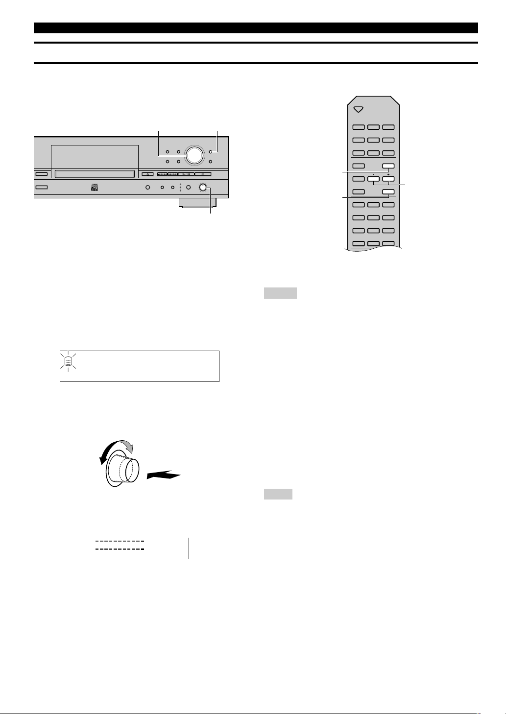
E-24
RECORDING FROM AN EXTERNAL COMPONENT ONTO THE HDD
Adjusting the Recording Level
There is an adjusting procedure for each input source to be recorded as explained below. Choose the one for your input source and follow the
steps.
ER
TEXT/TIME MODE
MULTI JOG
DIGITAL REC LEVEL
PUSH ENTER
TRACK NO.
FINALIZE ERASE
BOOKMARK
COMPLETE
MENU
CLEAR
MIN MAX
OPTICAL
ANALOG REC LEVEL
INPUT
REC
COAXIAL
ANALOG
COPY
A.M.Q.R.
MULTI JOG
ANALOG REC LEVEL
MENU
OPEN/CLOSE
COPY REC
TEXT/TIME
TRACK NO.
WRITE
MODE MENU
CLEAR
1
ABC2DEF3GHI
4
JKL5MNO6PQR
7
STU8VWX9YZ
SPACE
SYMBOL
0 +10
BOOKMARK
ENTER
COMPLETE
A.M.Q.R.
FINALIZE
INPUT
TIMER REC
ERASE
MENU
ENTER
+, –
■ When recording a digital input source
The digital recording level is set to 0dB, the level of the input
source, as an initial setting. Further adjustment is not normally
necessary. However it is possible to adjust the recording level to suit
your needs.
1. Press MENU while this unit is in the recording pause
mode.
The following message appears on the display.
2. Play the loudest passage (highest sound level) of the
source to be recorded.
3. Rotate the MULTI JOG knob (press +/– on the remote
control) to adjust the recording level.
Adjustment is possible in the –12dB to +12dB range by 0.4dB
steps.
Adjust the recording level so that the red part on the peak level
meter does not light at the loudest sound levels.
4. Press the MULTI JOG knob (ENTER on the remote
control) to return to the previous display.
Notes
• The recording level can be adjusted while this unit is in either the
recording or recording pause mode. Once recording has been
stopped, the recording level is reset to 0dB.
• Adjustment of the recording level can be canceled by pressing
MENU when the level is adjusted in the recording pause mode.
• The recording level is set to 0dB by pressing CLEAR when the
level is adjusted in the recording pause mode.
■ When recording an analog input source
1. Play the loudest passage (highest sound level) of the
source to be recorded.
2. Adjust the recording level by rotating the ANALOG
REC LEVEL control.
Rotate the control clockwise to increase the level and
counterclockwise to decrease the level.
Adjust the recording level so that the red part on the peak level
meter does not light at the loudest sound levels.
Note
• The recording level can be adjusted while this unit is in either the
recording or recording pause mode.
Level 0.0dB
REC
LEVEL
L
R
dB –30 –10 –6 –20
SYNC
L
R
dB –30 –10 –6 –20
Page 31

E-25
English
COPYING AND RECORDING ONTO THE HDD
RECORDING FROM AN EXTERNAL COMPONENT ONTO THE HDD
Advanced Operations
■ Making an additional recording onto an
already recorded disc
When recording onto the HDD, you can select the disc on the HDD
for your recording. Rotate the MULTI JOG knob (press GROUP
SKIP q/GROUP SKIP w on the remote control) to select the disc
number on which recordings are to be made while this unit is in the
recording pause mode.
Notes
• When no disc number is selected, recordings are made onto the
disc with the smallest number available on the HDD.
• When a disc with recorded tracks is selected, new recordings are
added to the end of the previous recordings.
Disc number on which recordings are to be made
ER
TEXT/TIME MODE
MULTI JOG
DIGITAL REC LEVEL
PUSH ENTER
TRACK NO.
FINALIZE ERASE
BOOKMARK
COMPLETE
MENU
CLEAR
MIN MAX
OPTICAL
ANALOG REC LEVEL
INPUT
REC
COAXIAL
ANALOG
COPY
A.M.Q.R.
MULTI JOG
4
JKL5MNO6PQR
7
STU8VWX9YZ
SPACE
SYMBOL
0 +10
BOOKMARK
REPEAT RANDOM
GROUP SKIP
INTRO
HDD CDR
GROUP SKIP wGROUP SKIP q
Dsc002 1 000
REC
GROUP
L
R
dB –30 –10 –6 –20
SYNC
■ Setting the recording mode
This unit provides various recording modes. Choose the one that
suits your needs.
Initial setting: Track Synchro
1. Press MODE while this unit is in the recording pause
mode.
The recording mode can be selected.
2. Rotate the MULTI JOG knob (press +/– on the remote
control) to select the recording mode.
Choose one of the modes listed below.
Manual (Manual recording mode)
All the recording operations including starting, stopping and
track marking are performed manually.
Track Synchro (Track-synchronized recording mode)
Starting and stopping are performed manually. Track markers
are automatically placed between the tracks being recorded.
Multi Synchro (Multi-synchronized recording mode)
This mode records the set number of tracks at the same time as
the source programs are being played. The number of tracks to
be recorded can be set in the range of 1 to 99 tracks. This mode
is convenient to record a mix of tracks from different sources.
All Synchro (All-synchronized recording mode)
This mode records all of the material from a single audio
source at the same time as the source programs are being
played. Track markers are automatically placed between the
tracks being recorded.
Auto Period (Auto-period recording mode)
This mode makes recording for the set amount of time while
placing track markers at the set time interval. The length
between track markers can be adjusted in the 10 seconds to 30
minutes range by 10-second steps. This mode is convenient to
search for material recorded from FM broadcasts.
OPEN/CLOSE
COPY REC
TEXT/TIME
TRACK NO.
WRITE
MODE MENU
CLEAR
1
ABC2DEF3GHI
ENTER
COMPLETE
A.M.Q.R.
FINALIZE
INPUT
TIMER REC
ERASE
MODE
ENTER
+, –
ER
TEXT/TIME MODE
MULTI JOG
DIGITAL REC LEVEL
PUSH ENTER
TRACK NO.
FINALIZE ERASE
BOOKMARK
COMPLETE
MENU
CLEAR
MIN MAX
OPTICAL
ANALOG REC LEVEL
INPUT
REC
COAXIAL
ANALOG
COPY
A.M.Q.R.
MODE MULTI JOG
Page 32

E-26
RECORDING FROM AN EXTERNAL COMPONENT ONTO THE HDD
3. Press the MULTI JOG knob (ENTER on the remote
control) to confirm the recording mode selected.
If “Manual”, “Track Synchro” or “All Synchro” is confirmed,
this unit returns the recording pause mode.
If “Multi Synchro” is confirmed, following message appears on
the display. Make a setting following steps 4 and 5.
If “Auto Period” is confirmed, following message appears on
the display. Make a setting following steps 6 to 9.
4. Select the number of tracks by rotating the MULTI
JOG knob (pressing +/– on the remote control).
The number can be set in the 1 to 99 tracks range.
5. Press the MULTI JOG knob (ENTER on the remote
control) to confirm the number of tracks to be set.
This unit returns to the recording pause mode.
6. Select the time length between track markers by
rotating the MULTI JOG knob (pressing +/– on the
remote control).
The time length can be set in the 10 seconds to 30 minutes
range by 10-seconds steps.
7. Press the MULTI JOG knob (ENTER on the remote
control) to confirm the time length between the
selected track markers.
The following message appears on the display. The total
recording time can be set.
8. Select the total recording time by rotating the MULTI
JOG knob (pressing +/– on the remote control).
9. Press the MULTI JOG knob (ENTER on the remote
control) to confirm the total recording time.
This unit returns to the recording pause mode.
Notes
• When recording to the HDD in the auto period recording mode,
the recording will be performed continuously to the next available
disc if the time length between selected track markers exceeds the
group remaining time.
• In the auto period recording mode, a time error can occur in a
frame unit. Therefore, the time of each track or the group total
time may not match the confirmed time length between selected
track markers or the total recording time.
How many ?1
REC
L
R
dB –30 –10 –6 –20
MULT SYNC
Period ? 300
AUTO PRD
REC
TIME
L
R
dB –30 –10 –6 –20
Total?0h4m
AUTO PRD
REC
TIME
L
R
dB –30 –10 –6 –20
■ Setting a condition at synchronized recording
This unit automatically detects track intervals when recording is
made in track-synchronized recording mode, multi-synchronized
recording mode, or all-synchronized recording mode. You can set
the condition for detecting track intervals. Setting items are as
follows:
OPT TH Level
Sets the signal level that judges the signals input through the
DIGITAL IN (OPTICAL) jack as “no signal”.
Initial setting: –50dB, Control range: –90 to –20dB
COAX TH Level
Sets the signal level that judges the signals input through the
DIGITAL IN (COAXIAL) jack as “no signal”.
Initial setting: –50dB, Control range: –90 to –20dB
ANLG TH Level
Sets the signal level that judges the signals input through the
ANALOG LINE IN (REC) jacks as “no signal”.
Initial setting: –40dB, Control range: –60 to –20dB
Int. Time
Sets the length of silence (“no signal”) that judges track intervals.
When the set amount of silence continues, this unit judges it as a
track interval and places a track marker.
Initial setting: 2.0 seconds, Control range: 0.5 to 5.0 seconds
End Duration
Sets the length of silence (“no signal”) that judges the end of
playback when recording in the all-synchronized recording mode.
When the set amount of silence continues, recording will be
stopped.
Initial setting: 12.0 seconds, Control range: 2.0 to 60.0 seconds
Note
• Settings for “Int. Time” and “End Duration” apply to each input
jack.
See next page for the setting procedure.
Page 33

E-27
English
COPYING AND RECORDING ONTO THE HDD
RECORDING FROM AN EXTERNAL COMPONENT ONTO THE HDD
■ Setting a condition for synchronized recording
1. Press MENU while this unit is in the stop mode.
Menu item selection appears on the display.
2. Rotate the MULTI JOG knob (press +/– on the remote
control) to select “Synchro Setup”.
3. Press the MULTI JOG knob (ENTER on the remote
control).
Setting item selection appears on the display.
4. Rotate the MULTI JOG knob (+/– on the remote
control) to select a setting item.
5. Press the MULTI JOG knob (ENTER on the remote
control) to confirm the setting item.
If “OPT TH Level”, “COAX TH Level” or “ANLG TH Level”
is confirmed, make a setting following steps 6 and 7.
If “Int. Time” or “End Duration” is confirmed, make a setting
following 8 and 9.
ER
TEXT/TIME MODE
MULTI JOG
DIGITAL REC LEVEL
PUSH ENTER
TRACK NO.
FINALIZE ERASE
BOOKMARK
COMPLETE
MENU
CLEAR
MIN MAX
OPTICAL
ANALOG REC LEVEL
INPUT
REC
COAXIAL
ANALOG
COPY
A.M.Q.R.
MULTI JOG MENU
OPEN/CLOSE
COPY REC
TEXT/TIME
TRACK NO.
WRITE
MODE MENU
CLEAR
1
ABC2DEF3GHI
ENTER
COMPLETE
A.M.Q.R.
FINALIZE
INPUT
TIMER REC
ERASE
MENU
+, –
ENTER
Synchro Setup
L
R
dB –30 –10 –6 –20
6. Rotate the MULTI JOG knob (press +/– on the remote
control) to adjust the level.
Level can be set by 1dB step.
Example: To set “ANLG TH Level”
7. Press the MULTI JOG knob (ENTER on the remote
control) to confirm the level.
Setting item selection appears on the display.
8. Rotate the MULTI JOG knob (+/– on the remote
control) to set an interval.
“Int. Time” can be set by 0.5-second steps, and “End Duration”
can be set by 1.0-second steps.
Example: To set “Int.Time”
9. Press the MULTI JOG knob (ENTER on the remote
control) to set an interval.
Setting item selection appears on the display.
Press MENU twice to close the menu and return to the normal stop
mode.
ANLG TH -40dB
LEVEL
L
R
dB –30 –10 –6 –20
Time 2.0sec
TIME
L
R
dB –30 –10 –6 –20
Page 34

E-28
■ Manual track marking
RECORDING FROM AN EXTERNAL COMPONENT ONTO THE HDD
ER
TEXT/TIME MODE
MULTI JOG
DIGITAL REC LEVEL
PUSH ENTER
TRACK NO.
FINALIZE ERASE
BOOKMARK
COMPLETE
MENU
CLEAR
MIN MAX
OPTICAL
ANALOG REC LEVEL
INPUT
REC
COAXIAL
ANALOG
COPY
A.M.Q.R.
TRACK NO./BOOKMARK
OPEN/CLOSE
COPY REC
TEXT/TIME
TRACK NO.
WRITE
MODE MENU
CLEAR
1
ABC2DEF3GHI
ENTER
COMPLETE
A.M.Q.R.
FINALIZE
INPUT
TIMER REC
ERASE
TRACK NO.
WRITE
This unit can automatically place track markers. However you can
also manually place track markers during your recording. (Manual
track marking)
Press TRACK NO./BOOKMARK (TRACK NO. WRITE on the
remote control) during your recording.
• A new track number is added at the location on the disc corre-
sponding to the time TRACK NO./BOOKMARK (TRACK NO.
WRITE on the remote control) is pressed.
• Manual track marking is possible after the recording has been
performed for 5 seconds from the beginning of the track, and a
disc cannot contain more than 99 tracks. Even if there is time
remaining on the disc, further recording is impossible once 99
track markers have been placed.
Notes
• The track markers may not be placed properly even if the
recording has been performed in the synchronized recording
according to the type of the source devices. To avoid this problem,
place the track markers manually.
• Manual track marking is possible even during synchronized
recording.
• You can place the track markers to the tracks that have been
recorded on the HDD by dividing the track. See “Track Divide”
on page 46.
Page 35

E-29
English
EDITING
EDITING MENU ITEMS
You can make various editing operations on the albums, tracks and discs on the HDD. The editing menu is listed below.
Album Edit
Track Edit
Disc Edit
Undo
Album New
Edit Stored
Album Copy
Album Rename
Album Delete
Album Pack
Album Title
Track Shuffle
Track Level
Tr. Interval
Track Rename
Track Adjust
Track Erase
Part Erase
Track Combine
Track Divide
Track Pack
Add Fade In
Add Fade Out
Track Title
Disc Rename
Disc Erase
Disc Combine
Disc Divide
Disc Pack
Disc Title
To create a new album
To edit an already created album
To copy other group as an album
To change the album number
To delete an album
To eliminate unused album numbers
To assign an album title
To change the order of tracks in an album
To adjust the track level in an album
To adjust each track interval in an album
To change a track number
To adjust the beginning of a track
To erase a track
To erase the part of a track
To combine a series of tracks
To divide one track into two
To eliminate unused track numbers
To add fade-in to the beginning of a track
To add fade-out to the end of a track
To assign a track title
To change a disc number
To erase a disc
To combine a series of discs
To divide one disc into two
To eliminate unused disc numbers
To assign a disc title
To cancel the editing operation
—
—
—
—
✓
—
✓
✓
✓
✓
✓
✓
✓
✓
✓
✓
—
✓
✓
✓
✓
✓
✓
✓
—
✓
—
31
31, 32
32
33
33
34
34, 35
35, 36
36, 37
38
40
41, 42
42
43, 44
45
46, 47
47
48, 49
49, 50
50, 51
53
54
54, 55
55, 56
56
57
58
Menu item Menu content
Selectable during
playback*
Page
*The item that can be selected during playback is marked with the ✓ mark.
■ Selection of the item during playback
Selectable item is changed as follows according to the playback status.
• Items with the ✓ mark in “Album Edit” can be selected while an album is being played.
• Items with the ✓ mark in “Track Edit” can be selected while a disc with the TRACK indicator turned on.
• Items with the ✓ mark in “Disc Edit” can be selected while a disc with the GROUP indicator turned on.
• No item can be selected while a bookmark is being played.
Notes
• To switch the GROUP indicator and the TRACK indicator, press the MULTI JOG knob.
• To switch the group to be played, rotate the MULTI JOG knob with the GROUP indicator turned on.
Alb001 1 001
ALBM
GROUP
L
R
dB –30 –10 –6 –2 0
G
Dsc001 1 001
TRACK
L
R
dB –30 –10 –6 –20
G
Dsc001 1 001
GROUP
L
R
dB –30 –10 –6 –20
G
Page 36

E-30
You can select the desired tracks from among the ones recorded on the HDD and store them as an album in this unit’s memory. You can also
edit the album afterwards.
Album Editing Operation
ALBUM EDITING
NATURAL SOUND HDD/CD RECORDER
TEXT/TIME MODE
MULTI JOG
DIGITAL REC LEVEL
PUSH ENTER
TRACK NO.
FINALIZE ERASE
BOOKMARK
COMPLETE
MENU
CLEAR
MIN MAX
OPTICAL
ANALOG REC LEVEL
INPUT
REC
COAXIAL
ANALOG
COPY
A.M.Q.R.
CDRHDD
MIN MAX
LEVELPHONES
POWER
MULTI JOG
HDD
MENU
OPEN/CLOSE
COPY REC
TEXT/TIME
TRACK NO.
WRITE
MODE MENU
CLEAR
1
ABC2DEF3GHI
4
JKL5MNO6PQR
7
STU8VWX9YZ
SPACE
SYMBOL
0 +10
BOOKMARK
ENTER
COMPLETE
A.M.Q.R.
FINALIZE
INPUT
TIMER REC
ERASE
4
JKL5MNO6PQR
7
STU8VWX9YZ
SPACE
SYMBOL
0 +10
BOOKMARK
REPEAT RANDOM
GROUP SKIP
INTRO
HDD CDR
+, –
ENTER
MENU
HDD
■ Editing during the stop mode
1. Press HDD to select the HDD.
2. Press MENU.
The display changes for the menu item selection.
3. Press MULTI JOG knob (ENTER on the remote
control).
The display changes for the editing the menu item selection.
4. Select the editing menu item to be set by rotating the
MULTI JOG knob (pressing +/– on the remote
control).
The followings are the album editing menu items.
• Album New
• Edit Stored
• Album Copy
• Album Rename
• Album Delete
• Album Pack
• Album Title
• Track Shuffle
• Track Level
• Tr. Interval
5. Press MULTI JOG knob (ENTER on the remote
control).
The selected item is confirmed. Then editing operation can be
started.
6. Start editing by following the setting steps (pages
31—38) for each item.
7. Press a when all editing has been completed.
The display changes to the one when this unit was in the stop
mode.
Album Edit
L
R
dB –30 –10 –6 –20
■ Editing during playback
1. Press MENU while the album to be edited is being
played.
The display changes for the editing menu item selection.
2. Select the editing menu item to be set by rotating the
MULTI JOG knob (pressing +/– on the remote
control).
The followings are the album editing menu items.
• Album Delete
• Album Title
• Track Shuffle
• Track Level
• Tr. Interval
3. Press MULTI JOG knob (ENTER on the remote
control).
The selected item is confirmed. Then editing operation can be
started.
4. Start editing by following the setting steps (pages
31—38) for each item.
Notes
• If MENU is pressed during editing, entry of the selection is
canceled, and then this unit returns to the following state;
– This unit returns to the editing menu item selection if having
started editing during the stop mode.
– This unit returns to the playback if having started editing during
the playback.
• If a is pressed during editing, all entry of the selection is
canceled, and this unit returns to the stop mode.
Page 37

E-31
English
EDITING
Album New
You can create a new album by selecting the desired tracks from
among the ones recorded on the HDD.
1. Select and confirm “Album New” in step 4 of “Editing
during the stop mode” on page 30.
The following message appears on the display.
The number of the source disc flashes.
2. Select the source disc by rotating the MULTI JOG
knob (pressing +/– on the remote control).
3. Press the MULTI JOG knob (ENTER on the remote
control) to confirm the source disc.
The number of the source track flashes.
Press CLEAR to cancel the confirmed selection.
4. Select the source track by rotating the MULTI JOG
knob (pressing +/– on the remote control).
5. Press the MULTI JOG knob (ENTER on the remote
control) to confirm the source track.
The track number of the album being created will be advanced
to the next, and the display returns to the one shown in step 1.
Repeat steps 2—5 to select other discs and tracks.
Press CLEAR to cancel the confirmed selection.
6. Press COMPLETE.
A new album is created with the selected tracks recorded on it.
This unit returns to the editing menu item selection.
Notes
• You can switch the display by pressing TEXT/TIME while an
album is being made:
– If the title is assigned to the source disc or track, the title
appears.
– By pressing TEXT/TIME while the title is being displayed, the
total time of the album being made appears for approximately 1
second, and the display returns to the one in step 1.
– If no title is assigned to the source disc or track, the total time of
the album being made appears for approximately 1 second, and
the display returns to the one in step 1.
• You can create a new album using the tracks with bookmarks (see
“Album Copy” on page 32). Also see “BOOKMARK” on page
59.
ALBUM EDITING
Edit Stored
You can add tracks to or delete tracks from an already created
album.
1. Select and confirm “Edit Stored” in step 4 of “Editing
during the stop mode” on page 30.
The following message appears on the display.
The number of the album to be edited flashes.
2. Select the album to be edited by rotating the MULTI
JOG knob (pressing +/– on the remote control).
3. Press the MULTI JOG knob (ENTER on the remote
control) to confirm the album to be edited.
The following message appears on the display.
■ When adding new tracks
4. Select the track to be added by pressing t/e or
r/y.
5. Select the disc that contains the track to be added by
rotating the MULTI JOG knob (pressing +/– on the
remote control).
6. Press the MULTI JOG knob (ENTER on the remote
control) to confirm the disc that contains the track to
be added.
Press CLEAR to cancel the confirmed selection.
Edit 001 ?
GROUP
L
R
dB –30 –10 –6 –2 0
Album to be edited
Disc that contains the
tracks to be added Track to be added
Track to be added or deleted
Dsc001 1≥ 15
GROUP
L
R
dB –30 –10 –6 –20
Source disc
Track in the album to be created
Source track
Dsc001 1≥1
GROUP
L
R
dB –30 –10 –6 –20
Continues to next page
Page 38

E-32
Album Copy
You can copy the entire disc, album, or bookmark to a new album.
1. Select and confirm “Album Copy” in step 4 of
“Editing during the stop mode” on page 30.
The following message appears on the display.
The number of the group to be copied from flashes.
2. Select the group to be copied from by rotating the
MULTI JOG knob (pressing +/– on the remote
control).
The group to be copied from switches in the order of “disc” ➞
“album” ➞ “bookmark”.
3. Press the MULTI JOG knob (ENTER on the remote
control) to confirm the group to be copied from.
The display scrolls to the left to indicate the number of the
group to be copied from and the number of the album to be
copied to. The album to be copied on is assigned the smallest
available number.
Press CLEAR to cancel the confirmed selection.
4. Press COMPLETE.
The selected group is copied to a new album.
This unit returns to the editing menu item selection.
ALBUM EDITING
7. Select the track to be added by rotating the MULTI
JOG knob (pressing +/– on the remote control).
8. Press the MULTI JOG knob (ENTER on the remote
control) to confirm the track to be added.
When continuing to add tracks to the album, repeat steps 4—8.
9. Press COMPLETE.
The selected tracks are added to the album.
This unit returns to the editing menu item selection.
■ When deleting tracks from the album
4. Select the track to be deleted by pressing t/e or
r/y.
5. Press CLEAR.
Note
• The tracks following the deleted track will automatically be
down-numbered.
When continuing to delete tracks from the album, repeat steps
4 and 5.
6. Press COMPLETE.
The selected tracks are deleted from the album.
This unit returns to the editing menu item selection.
Group to be copied from
Copy Dsc001?
GROUP
L
R
dB –30 –10 –6 –2 0
Dsc001≥002
GROUP
L
R
dB –30 –10 –6 –20
Group to be copied from Album to be copied to
Page 39

E-33
English
EDITING
ALBUM EDITING
Album Rename
You can move the album and assign a new number.
1. Select and confirm “Album Rename” in step 4 of
“Editing during the stop mode” on page 30.
The following message appears on the display.
The number of the album to be moved flashes.
2. Select the album to be moved by rotating the MULTI
JOG knob (pressing +/– on the remote control).
3. Press the MULTI JOG knob (ENTER on the remote
control) to confirm the album to be moved.
The display scrolls to the left to indicate the number of the
album to be moved and the new album number.
Press CLEAR to cancel the confirmed selection.
4. Select the new album number by rotating the MULTI
JOG knob (pressing +/– on the remote control).
5. Press the MULTI JOG knob (ENTER on the remote
control) to confirm the new album number.
Press CLEAR to cancel the confirmed selection.
6. Press COMPLETE.
The selected album has been moved and assigned a new
number.
This unit returns to the editing menu item selection.
Notes
• If the selected new album number is already in use, the albums
following this renumbered album will be automatically upnumbered by one. However, if there is any unused album number,
only the albums up to that number will be up-numbered.
• The original number of the album that has been renumbered will
be available for future use.
Album to be moved
Album to be moved New album number
Rename 001?
GROUP
L
R
dB –30 –10 –6 –20
Alb001≥ 002
GROUP
L
R
dB –30 –10 –6 –20
Album Delete
You can delete an existing album.
■ Editing during the stop mode
1. Select and confirm “Album Delete” in step 4 of
“Editing during the stop mode” on page 30.
The following message appears on the display.
The number of the album to be deleted flashes.
2. Select the album to be deleted by rotating the MULTI
JOG knob (pressing +/– on the remote control).
3. Press the MULTI JOG knob (ENTER on the remote
control) to confirm the album to be deleted.
Press CLEAR to cancel the confirmed selection.
4. Press COMPLETE.
The selected album has been deleted.
This unit returns to the editing menu item selection.
■ Editing during playback
1. Select and confirm “Album Delete” in step 2 of
“Editing during playback” on page 30.
The album being played is confirmed to be deleted.
2. Press COMPLETE.
The album being played will be deleted.
Playback resumes from the beginning of the next album after
the deleted album. If no album follows the deleted album, this
unit plays the previous album of the deleted album.
Note
• The number of the deleted album will be available for future use.
Delete 001?
GROUP
L
R
dB –30 –10 –6 –20
Album to be deleted
Page 40

E-34
ALBUM EDITING
Album Pack
You can re-organize the album numbers by eliminating unused
album numbers that have been created by changing album numbers
or deleting albums.
1. Select and confirm “Album Pack” in step 4 of “Editing
during the stop mode” on page 30.
The following message appears on the display.
2. Press COMPLETE.
The album numbers are re-organized without unused album
numbers.
This unit returns to the editing menu item selection.
Album Title
You can assign a title to a created album.
■ Editing during the stop mode
1. Select and confirm “Album Title” in step 4 of “Editing
during the stop mode” on page 30.
The following message appears on the display.
The number of the album to assign a title to flashes.
2. Select the album to assign a title to by rotating the
MULTI JOG knob (pressing +/– on the remote
control).
Pack ?
L
R
dB –30 –10 –6 –20
Title 001?
GROUP
L
R
dB –30 –10 –6 –20
Album to assign the title to
3. Press the MULTI JOG knob (ENTER on the remote
control) to confirm the album to assign a title to.
The following message appears on the display.
The cursor flashes.
If the selected album already has a title, the title appears on the
display.
4. Enter the title characters by using the MULTI JOG
knob or the alphabetical/numeric buttons on the
remote control.
See next page for entering procedure.
5. Press COMPLETE when all the characters have been
entered.
The title is assigned to the selected album.
This unit returns to the editing menu item selection.
■ Editing during playback
1. Select and confirm “Album Title” in step 2 of “Editing
during playback” on page 30.
The album being played is confirmed for assigning the title to.
The following message appears on the display.
The cursor flashes.
If the selected album already has a title, the title appears on the
display.
2. Enter the title characters by using the MULTI JOG
knob or the alphabetical/numeric buttons on the
remote control.
See next page for entering procedure.
3. Press COMPLETE when all the characters have been
entered.
The title is assigned to the selected album.
Playback resumes from the beginning of the album with the
title assigned to.
Continues to next page
ALBM
L
R
dB –30 –10 –6 –20
G
L
R
dB –30 –10 –6 –20
Before “Album Pack” is performed
After “Album Pack” has been performed (Unused album numbers
have been eliminated.)
: Unused album numbers
1346
123456
Page 41

E-35
English
EDITING
ALBUM EDITING
■ Entering the title characters by using the
MULTI JOG knob
1. Rotate the MULTI JOG knob clockwise.
When the MULTI JOG knob is rotated clockwise, characters
appear in the order of alphabetical capital letters, alphabetical
lower case letters, numbers, and symbols. Select the character
you wish to use for the title.
2. Press the MULTI JOG knob to confirm the selected
character.
The cursor moves to the next space. Repeat steps 1 and 2 until
the title is complete. A title can contain up to 32 characters.
■ Entering the title characters by using the
alphabetical/numeric buttons on the remote
control
1. Select the character to be used for the title by using
the alphabetical/numeric buttons on the remote
control.
Alphabetical capital letters, alphabetical lower case letters, and
numbers switch each time the buttons are pressed. To create a
space, press SPACE. To use a symbol, press SYMBOL to
select the desired symbol.
2. Select the next character by pressing one of the
alphabetical/numeric buttons.
The cursor automatically moves to the next space. When the
same button is used, press y to move the cursor to the next
space.
Note
• If a new character is entered on the existing character, the new
character is inserted in front of the existing character.
■ Correcting the characters
Move the cursor to the character to be corrected by pressing t/
e or r/y (t or y on the remote control). Press CLEAR to
cancel the character before a new character is entered. Then enter
and confirm the new character.
Track Shuffle
You can change the order of tracks in an album.
■ Editing during the stop mode
1. Select and confirm “Track Shuffle” in step 4 of
“Editing during the stop mode” on page 30.
The following message appears on the display.
The number of the album to change its tracks’ order flashes.
2. Rotate the MULTI JOG knob (press +/– on the remote
control) to select the album to change its tracks’
order.
3. Press the MULTI JOG knob (ENTER on the remote
control) to confirm the album to change its tracks’
order.
The number of the track to be moved flashes.
Press CLEAR to cancel the confirmed selection.
4. Rotate the MULTI JOG knob (+/– on the remote
control) to select the track to be moved.
5. Press the MULTI JOG knob (ENTER on the remote
control) to confirm the track to be moved.
The display scrolls to the left to indicate the number of the
album to change its tracks’ order, the number of the track to be
moved, and the new track number.
Press CLEAR to cancel the confirmed selection.
Continues to next page
Track to be moved
Shuffle001 1?
GROUP
L
R
dB –30 –10 –6 –20
Album to change its tracks’ order
New track number
001 1≥ 2
TRACK
L
R
dB –30 –10 –6 –20
Track to be movedAlbum to change its
tracks’ order
Page 42

E-36
ALBUM EDITING
6. Rotate the MULTI JOG knob (press +/– on the remote
control) to select the new track number.
7. Press the MULTI JOG knob (ENTER on the remote
control) to confirm the new track number.
Press CLEAR to cancel the confirmed selection.
8. Press COMPLETE.
The selected track has been moved and assigned a new number.
This unit returns to the editing menu item selection.
■ Editing during playback
1. Select and confirm “Track Shuffle” in step 2 of
“Editing during playback” on page 30.
The track being played is confirmed to be moved.
The number of the album and track being played and the new
track number appear on the display.
2. Rotate the MULTI JOG knob (press +/– on the remote
control) to select the new track number.
3. Press the MULTI JOG knob (ENTER on the remote
control) to confirm the new track number.
Press CLEAR to cancel the confirmed selection.
4. Press COMPLETE.
The track being played has been moved and assigned a new
number.
Playback resumes from the beginning of the moved track.
New track number
001 1≥ 2
ALBM
TRACK
L
R
dB –30 –10 –6 –2 0
G
Track being playedAlbum being played
Track Level
You can adjust the sound level of track in an album.
■ Editing during the stop mode
1. Select and confirm “Track Level” in step 4 of “Editing
during the stop mode” on page 30.
The following message appears on the display.
The number of the album to adjust its tracks’ level flashes.
2. Rotate the MULTI JOG knob (press +/– on the remote
control) to select the album to adjust its tracks’ level.
3. Press the MULTI JOG knob (ENTER on the remote
control) to confirm the album to adjust its tracks’
level.
The number of the track to adjust its level flashes.
Press CLEAR to cancel the confirmed selection.
4. Rotate the MULTI JOG knob (+/– on the remote
control) to select the track to adjust.
5. Press the MULTI JOG knob (ENTER on the remote
control) to confirm the track to adjust its level.
Playback of the confirmed track starts, and the following
message appears on the display.
Press CLEAR to cancel the confirmed selection.
Continues to next page
Track to adjust its level
Level 001 1?
GROUP
L
R
dB –30 –10 –6 –20
Album to adjust its tracks’ level
Tr. 1 0.0dB
LEVEL
L
R
dB –30 –10 –6 –20
Track to adjust its level
Page 43

E-37
English
EDITING
ALBUM EDITING
6. Rotate the MULTI JOG knob (press +/– on the remote
control) to adjust the level.
Adjustment is possible in the –12dB to +12dB range by 0.4dB
steps.
You can compare the level with the previous or next tracks’
level by pressing t/e or r/y (t or y on the remote
control).
You can also search the passage in the selected track by
pressing and holding t/e or r/y (e or r on the
remote control).
7. Press COMPLETE.
The level of the selected track is confirmed.
This unit returns to the editing menu item selection.
■ Editing during playback
1. Select and confirm “Track Level” in step 2 of “Editing
during playback” on page 30.
The track being played is confirmed to adjust its level.
The following message appears on the display.
2. Rotate the MULTI JOG knob (press +/– on the remote
control) to adjust the level.
Adjustment is possible in the –12dB to +12dB range by 0.4dB
steps.
You can compare the level with the previous or next tracks’
level by pressing t/e or r/y (t or y on the remote
control).
You can also search the passage in the selected track by
pressing and holding t/e or r/y (e or r on the
remote control).
3. Press COMPLETE.
The level of the track being played is confirmed.
Playback resumes from the beginning of the track with its level
adjusted.
Notes
• The level may change slightly out of the point that the track itself
changes during the playback of the album with its tracks’ level
adjusted. In this case, add the 1-to-2 second interval using the “Tr.
Interval” function described on the next page.
• You can not copy the album with its tracks’ level adjusted in the
Audio Master Quality Recording mode (see page 63).
• You can also adjust the copy level (see page 66) when copying the
album with its tracks’ level adjusted. The copy will be made in the
total level adjusted in “Track Level” and “Copy Level” on the
copy menu.
Tr. 1 0.0dB
ALBM
LEVEL
L
R
dB –30 –10 –6 –2 0
G
Track being played
Page 44

E-38
ALBUM EDITING
Tr. Interval
You can adjust each track interval in an album.
■ Editing during the stop mode
1. Select and confirm “Tr. Interval” in step 4 of “Editing
during the stop mode” on page 30.
The following message appears on the display.
The number of the album to adjust its tracks’ interval flashes.
2. Rotate the MULTI JOG knob (press +/– on the remote
control) to select the album to adjust its tracks
interval.
3. Press the MULTI JOG knob (ENTER on the remote
control) to confirm the album to adjust its tracks
interval.
The number of the track to be adjusted flashes.
Press CLEAR to cancel the confirmed selection.
4. Rotate the MULTI JOG knob (+/– on the remote
control) to select the track to adjust its interval
between the previous track.
5. Press the MULTI JOG knob (ENTER on the remote
control) to confirm the track to adjust its interval
between the previous track.
The ending of the previous track for 5 seconds and the
beginning of the confirmed track for 5 seconds will be
repeatedly played.
The following message appears on the display.
Press CLEAR to cancel the confirmed selection.
Note
• If there is no track before the track that is selected and
confirmed, “No Previous” appears on the display, and this
unit returns to step 4.
Int. 001 1?
GROUP
L
R
dB –30 –10 –6 –20
Track to adjust its interval between the previous track
Album to adjust its track interval
Int:3.5 513
TIME
L
R
dB –30 –10 –6 –20
Playing time of the trackTrack interval
6. Rotate the MULTI JOG knob (press +/– on the remote
control) to adjust the interval.
Adjustment is possible in the 0 to 9.9 seconds range by 0.1second steps.
If you stop rotating the MULTI JOG knob, the ending of the
previous track for 5 seconds and the beginning of the confirmed track for 5 seconds will be repeatedly played with the
adjusted interval.
7. Press COMPLETE.
The interval between the selected track and the previous track
is confirmed.
This unit returns to the editing menu item selection.
■ Editing during playback
1. Select and confirm “Tr. Interval” in step 2 of “Editing
during playback” on page 30.
The track being played is confirmed to adjust its interval.
The ending of the previous track for 5 seconds and the
beginning of the confirmed track for 5 seconds will be
repeatedly played.
The following message appears on the display.
2. Rotate the MULTI JOG knob (press +/– on the remote
control) to adjust the interval.
Adjustment is possible in the 0 to 9.9 seconds range by 0.1second steps.
If you stop rotating the MULTI JOG knob, the ending of the
previous track for 5 seconds and the beginning of the confirmed track for 5 seconds will be repeatedly played with the
adjusted interval.
3. Press COMPLETE.
The interval between the selected track and the previous track
is confirmed.
Playback resumes from the beginning of the track with its
interval between the previous track adjusted.
Int:3.5 513
ALBM
TIME
L
R
dB –30 –10 –6 –20
G
Playing time of the trackTrack interval
Page 45

E-39
English
EDITING
You can do various editing operations on the tracks that have been recorded on the HDD.
Track Editing Operation
TRACK EDITING
NATURAL SOUND HDD/CD RECORDER
TEXT/TIME MODE
MULTI JOG
DIGITAL REC LEVEL
PUSH ENTER
TRACK NO.
FINALIZE ERASE
BOOKMARK
COMPLETE
MENU
CLEAR
MIN MAX
OPTICAL
ANALOG REC LEVEL
INPUT
REC
COAXIAL
ANALOG
COPY
A.M.Q.R.
CDRHDD
MIN MAX
LEVELPHONES
POWER
MULTI JOG
HDD
MENU
OPEN/CLOSE
COPY REC
TEXT/TIME
TRACK NO.
WRITE
MODE MENU
CLEAR
1
ABC2DEF3GHI
4
JKL5MNO6PQR
7
STU8VWX9YZ
SPACE
SYMBOL
0 +10
BOOKMARK
ENTER
COMPLETE
A.M.Q.R.
FINALIZE
INPUT
TIMER REC
ERASE
4
JKL5MNO6PQR
7
STU8VWX9YZ
SPACE
SYMBOL
0 +10
BOOKMARK
REPEAT RANDOM
GROUP SKIP
INTRO
HDD CDR
+, –
ENTER
MENU
HDD
■ Editing during the stop mode
1. Press HDD to select the HDD.
2. Press MENU.
The display changes for the menu item selection.
3. Select “Track Edit” by rotating the MULTI JOG knob
(pressing +/– on the remote control).
4. Press MULTI JOG knob (ENTER on the remote
control).
The display changes for the editing menu item selection.
5. Select the menu item by rotating the MULTI JOG knob
(pressing +/– on the remote control).
The followings are the track editing menu items:
• Track Rename
• Track Adjust
• Track Erase
• Part Erase
• Track Combine
• Track Divide
• Track Pack
• Add Fade In
• Add Fade Out
• Track Title
6. Press MULTI JOG knob (ENTER on the remote
control).
The selected item is confirmed. Then editing operation can be
started.
7. Start editing by following the setting details (pages
40—51) for each menu item.
8. Press a when all editing has been completed.
This unit returns to the stop mode.
Track Edit
L
R
dB –30 –10 –6 –20
■ Editing during playback
Press MULTI JOG knob to light up the TRACK indicator.
1. Press MENU while the track (in the disc) to be edited
is being played.
The display changes for the editing menu item selection.
2. Select the menu item by rotating the MULTI JOG knob
(pressing +/– on the remote control).
The followings are the track editing menu items:
• Track Rename
• Track Adjust
• Track Erase
• Part Erase
• Track Combine
• Track Divide
• Add Fade In
• Add Fade Out
• Track Title
3. Press MULTI JOG knob (ENTER on the remote
control).
The selected item is confirmed. Then editing operation can be
started.
4. Start editing by following the setting details (pages
40—51) for each menu item.
Notes
• If MENU is pressed during editing, entry of the selection is
canceled, and then this unit returns to the following state;
– This unit returns to the editing menu item selection if having
started editing during the stop mode.
– This unit returns to the playback if having started editing during
playback.
• If a is pressed during editing, all entry of the selection is
canceled, and this unit returns to the stop mode.
Page 46

E-40
TRACK EDITING
Track Rename
You can move a track and assign a new number.
■ Editing during the stop mode
1. Select and confirm “Track Rename” in step 5 of
“Editing during the stop mode” on page 39.
The following message appears on the display.
The disc number that contains the track to be moved flashes.
2. Select the disc that contains the track to be moved by
rotating the MULTI JOG knob (pressing +/– on the
remote control).
3. Press the MULTI JOG knob (ENTER on the remote
control) to confirm the disc that contains the track to
be moved.
The number of the track to be moved flashes.
Press CLEAR to cancel the confirmed selection.
4. Select the track to be moved by rotating the MULTI
JOG knob (pressing +/– on the remote control).
5. Press the MULTI JOG knob (ENTER on the remote
control) to confirm the track to be moved.
The display scrolls to the left to indicate the disc number that
contains the track to be moved, the existing track number, and
the new track number.
Press CLEAR to cancel the confirmed selection.
6. Select the new track number by rotating the MULTI
JOG knob (pressing +/– on the remote control).
7. Press the MULTI JOG knob (ENTER on the remote
control) to confirm the new track number.
Press CLEAR to cancel the confirmed selection.
8. Press COMPLETE.
The selected track is renumbered.
This unit returns to the editing menu item selection.
■ Editing during playback
1. Select and confirm “Track Rename” in step 2 of
“Editing during playback” on page 39.
The track being played is confirmed to be moved and assigned
a new number.
The number of the disc and track being played and the new
track number appear on the display.
2. Select the new track number by rotating the MULTI
JOG knob (pressing +/– on the remote control).
3. Press the MULTI JOG knob (ENTER on the remote
control) to confirm the new track number.
Press CLEAR to cancel the confirmed selection.
4. Press COMPLETE.
The track being played is moved and assigned a new number.
Playback resumes from the beginning of the renumbered track.
Notes
• If the selected new track number is already in use, the tracks
following this renumbered track will be automatically upnumbered by one. However, if there is any unused track number,
only the tracks up to that number will be up-numbered.
• The original number of the track that has been renumbered will be
available for future use.
New track number
001 1≥ 1
TRACK
L
R
dB –30 –10 –6 –20
G
Disc being played
Disc that contains the track to be moved
Existing track number New track number
001 1≥ 1
TRACK
L
R
dB –30 –10 –6 –20
Disc that contains the track to be moved
Track to be moved
Rename 001 1?
GROUP
L
R
dB –30 –10 –6 –20
Track being played
Page 47

E-41
English
EDITING
TRACK EDITING
Track Adjust
You can change the beginning of the track to either earlier or later.
■ Editing during the stop mode
1. Select and confirm “Track Adjust” in step 5 of
“Editing during the stop mode” on page 39.
The following message appears on the display.
The disc number that contains the track to be adjusted flashes.
2. Select the disc that contains the track to be adjusted
by rotating the MULTI JOG knob (pressing +/– on the
remote control).
3. Press the MULTI JOG knob (ENTER on the remote
control) to confirm the disc that contains the track to
be adjusted.
The number of the track to be adjusted flashes.
Press CLEAR to cancel the confirmed selection.
4. Select the track to be adjusted by rotating the MULTI
JOG knob (pressing +/– on the remote control).
5. Press the MULTI JOG knob (ENTER on the remote
control) to confirm the track to be adjusted.
The confirmed track will be played.
The following message appears in the display.
Note
• If there is no track before the track that is selected and
confirmed, “No Previous” appears on the display, and this
unit returns to step 4.
6. Adjust the time length to change the beginning of the
track by rotating the MULTI JOG knob (pressing +/–
on the remote control).
The time length can be adjusted by “minute: second: frame”.
(Frame is the unit used for values smaller than 1 second. 75
frames make 1 second.) The unit to be set is flashing. Move the
flash to the unit to be adjusted by pressing t/e or r/y.
If you stop rotating the MULTI JOG knob, this unit searches
for the temporarily changed beginning point of the track
according to the time length setting made, and starts repeated
playback from the new beginning point to the end of the disc.
Press CLEAR to cancel the adjustment.
7. Press COMPLETE.
The new track beginning point is set.
This unit returns to the editing menu item selection.
■ Editing during playback
1. Select and confirm “Track Adjust” in step 2 of
“Editing during playback” on page 39.
The track being played is confirmed to be adjusted.
The following message appears on the display.
Note
• If there is no track before the track that is selected and
confirmed, “No Previous” appears on the display, and this
unit returns to the playback.
2. Adjust the time length to change the beginning of the
track by rotating the MULTI JOG knob (pressing +/–
on the remote control).
The time length can be adjusted by “minute: second: frame”.
The unit to be set is flashing. Move the flash to the unit to be
adjusted by pressing t/e or r/y.
If you stop rotating the MULTI JOG knob, this unit searches
for the temporarily changed beginning point of the track
according to the time length setting made, and starts repeated
playback from the new beginning point to the end of the disc.
Press CLEAR to cancel the adjustment.
Continues to next page
Disc that contains the track to be adjusted
Track to be adjusted
Adjust 001 2?
GROUP
L
R
dB –30 –10 –6 –2 0
The time length to be adjusted
012 + 01000
TIME
Playing time of the track
012 + 01000
TIME
G
The time length to be adjusted
Playing time of the track
Page 48

E-42
TRACK EDITING
3. Press COMPLETE.
The new track beginning point is set.
Playback resumes from the beginning of the adjusted track.
Notes
• If the adjusted track includes a part that cannot be copied digitally
before adjusting, the adjusted track itself cannot be copied
digitally either.
• When the emphasis status of the track to be adjusted is different
from that of the previous track, the emphasis status of the track to
be adjusted takes precedence over that of the previous track.
Track Erase
You can erase a selected track.
■ Editing during the stop mode
1. Select and confirm “Track Erase” in step 5 of “Editing
during the stop mode” on page 39.
The following message appears on the display.
The disc number that contains the track to be erased flashes.
2. Select the disc that contains the track to be erased
by rotating the MULTI JOG knob (pressing +/– on the
remote control).
3. Press the MULTI JOG knob (ENTER on the remote
control) to confirm the disc that contains the track to
be erased.
The number of the track to be erased flashes.
Press CLEAR to cancel the confirmed selection.
4. Select the track to be erased by rotating the MULTI
JOG knob (pressing +/– on the remote control).
Before “Track Adjust” is performed
After “Track Adjust” has been performed (The beginning
of track 2 is adjusted earlier.)
12
12
5. Press the MULTI JOG knob (ENTER on the remote
control) to confirm the track to be erased.
Press CLEAR to cancel the confirmed selection.
To check the track to be erased, press w/d (w on the remote
control). This unit starts to play the track to be erased
repeatedly.
6. Press COMPLETE.
The selected track is erased.
This unit returns to the editing menu item selection.
■ Editing during playback
1. Select and confirm “Track Erase” in step 2 of “Editing
during playback” on page 39.
The track being played is confirmed to be erased.
2. Press COMPLETE.
The track being played is erased.
Playback resumes from the beginning of the next track after the
erased track. If no track follows the erased track, this unit plays
the previous track of the erased track.
Note
• The number of the track that has been erased will be available for
future use.
Erase 001 1?
GROUP
L
R
dB –30 –10 –6 –20
Track to be erased
Disc that contains the track to be erased
Page 49

E-43
English
EDITING
TRACK EDITING
Part Erase
You can erase part of a selected track.
■ Editing during the stop mode
1. Select and confirm “Part Erase” in step 5 of the
“Editing during the stop mode” on page 39.
The following message appears on the display.
The disc number that contains the track to be partially erased
flashes.
2. Select the disc that contains the track to be partially
erased by rotating the MULTI JOG knob (pressing +/–
on the remote control).
3. Press the MULTI JOG knob (ENTER on the remote
control) to confirm the disc that contains the track to
be partially erased.
The number of the track to be partially erased flashes.
Press CLEAR to cancel the confirmed selection.
4. Select the track to be partially erased by rotating the
MULTI JOG knob (pressing +/– on the remote
control).
5. Press the MULTI JOG knob (ENTER on the remote
control) to confirm the track to be partially erased.
The passage between the point that is 5 seconds before the
temporary beginning point of the partial erase and the
temporary beginning point (the point that is 10 seconds elapsed
from the beginning of the track) is repeatedly played.
The following message appears on the display.
6. Set the beginning point of the partial erase by
rotating the MULTI JOG knob (pressing +/– on the
remote control).
The beginning point of the partial erase can be set by “minute:
second: frame”. The unit to be set is flashing. Move the flash to
the unit to be set by pressing t/e or r/y.
If you stop rotating the MULTI JOG knob, this unit searches
for the beginning point according to the setting made, and starts
repeated playback of the passage between the point that is 5
seconds before the beginning point and the beginning point.
7. Press MULTI JOG knob (ENTER on the remote
control) to confirm the beginning point of the partial
erase.
The passage between the temporary ending point of the partial
erase (the point that is 10 seconds after the beginning point)
and the point that is 5 seconds after the temporary ending point
is repeatedly played.
The following message appears on the display.
Press CLEAR to cancel the confirmed selection.
8. Set the ending point of the partial erase by rotating
the MULTI JOG knob (pressing +/– on the remote
control).
The ending point of the partial erase can be set by “minute:
second: frame”. The unit to be set is flashing. Move the flash to
the unit to be set by pressing t /e or r/y.
If you stop rotating the MULTI JOG knob, this unit searches
for the ending point according to the setting made, and starts
repeated playback of the passage between the ending point and
the point that is 5 seconds after the ending point.
9. Press MULTI JOG knob (ENTER on the remote
control) to confirm the ending point of the partial
erase.
The passage between the point that is 5 seconds before the
beginning point and the point that is 5 seconds after the ending
point of the partial erase is repeatedly played.
The following message appears on the display.
Caution
• During the playback of the passage mentioned above, the
sound may missing at the joint between the passage before
the beginning point and the passage after the ending point.
However, the partially erased track is played properly after
the partial erase has been completed.
To change the ending point, press CLEAR once to return to
step 8.
To change the beginning point, press CLEAR twice to return to
step 6.
10.
Press COMPLETE.
The selected part is erased.
This unit returns to the editing menu item selection.
Ending point of the partial erase
020 Ed 02000
TIME
Playing time of the track
Continues to next page
Prt.Er.001 1?
GROUP
L
R
dB –30 –10 –6 –20
Disc that contains the track to be partially erased
Track to be partially erased
005 St 01000
TIME
Beginning point of the partial erase
Playing time of the track
Prt.Er. 005
L
R
dB –30 –10 –6 –20
Pt.Fix 006
L
R
dB –30 –10 –6 –20
Page 50

E-44
TRACK EDITING
■ Editing during playback
1. Select and confirm “Part Erase” in step 2 of “Editing
during playback” on page 39.
The track being played is confirmed to be partially erased.
The passage between the point that is 5 seconds before the
beginning point of the partial erase and the beginning point
(the timing you press MENU) is repeatedly played.
The following message appears on the display.
2. Set the beginning point of the partial erase by
rotating the MULTI JOG knob (pressing +/– on the
remote control).
The beginning point of the partial erase can be set by “minute:
second: frame”. The unit to be set is flashing. Move the flash to
the unit to be set by pressing t/e or r/y.
If you stop rotating the MULTI JOG knob, this unit searches
for the beginning point according to the setting made, and starts
repeated playback of the passage between the point that is 5
seconds before the beginning point and the beginning point.
3. Press MULTI JOG knob (ENTER on the remote
control) to confirm the beginning point of the partial
erase.
The passage between the temporary ending point of the partial
erase (the point that is 10 seconds after the beginning point)
and the point that is 5 seconds after the temporary ending point
is repeatedly played.
The following message appears on the display.
Press CLEAR to cancel the confirmed selection.
4. Set the ending point of the partial erase by rotating
the MULTI JOG knob (pressing +/– on the remote
control).
The ending point of the partial erase can be set by “minute:
second: frame”. The unit to be set is flashing. Move the flash to
the unit to be set by pressing t /e or r/y.
If you stop rotating the MULTI JOG knob, this unit searches
for the ending point according to the setting made, and starts
repeated playback of the passage between the ending point and
the point that is 5 seconds after the ending point.
5. Press MULTI JOG knob (ENTER on the remote
control) to confirm the ending point of the partial
erase.
The passage between the point that is 5 seconds before the
beginning point and the point that is 5 seconds after the ending
point of the partial erase is repeatedly played.
The following message appears on the display.
Caution
• During the playback of the passage mentioned above, the
sound may missing at the joint between the passage before
the beginning point and the passage after the ending point.
However, the partially erased track is played properly after
the partial erase has been completed.
To change the ending point, press CLEAR once to return to
step 4.
To change the beginning point, press CLEAR twice to return to
step 2.
6. Press COMPLETE.
The selected part is erased.
Playback resumes from the beginning of the partially erased
track.
Caution
• The minimum length of a track is 4 seconds. It is not possible to
create a track that is shorter than 4 seconds by a partial erase.
Prt.Er. 005
L
R
dB –30 –10 –6 –20
G
Pt.Fix 006
L
R
dBG–30 –10 –6 –20
005 St 01000
TIME
Beginning point of the partial erase
Playing time of the track
020 Ed 02000
TIME
G
Ending point of the partial erase
Playing time of the track
1 2
3
Track
Track
: Part to be erased
1 Repeated passage when setting the beginning point
2 Repeated passage when setting the ending point
3 Repeated passage after confirming the ending point
Page 51

E-45
English
EDITING
TRACK EDITING
Track Combine
You can combine a series of tracks into one.
■ Editing during the stop mode
1. Select and confirm “Track Combine” in step 5 of
“Editing during the stop mode” on page 39.
The following message appears on the display.
The disc number that contains the first track to be combined
flashes.
2. Select the disc that contains the first track to be
combined by rotating the MULTI JOG knob (pressing
+/– on the remote control).
3. Press the MULTI JOG knob (ENTER on the remote
control) to confirm the disc that contains the first
track to be combined.
The number of the track to be the first in the combination
flashes.
Press CLEAR to cancel the confirmed selection.
4. Select the track to be the first in the combination by
rotating the MULTI JOG knob (pressing +/– on the
remote control).
5. Press the MULTI JOG knob (ENTER on the remote
control) to confirm the track to be the first in the
combination.
The display scrolls to the left to indicate the disc number that
contains the first track to be combined, the track number to be
the first in the combination, and the track number to be the last
in the combination.
Press CLEAR to cancel the confirmed selection.
6. Select the track to be the last in the combination by
rotating the MULTI JOG knob (pressing +/– on the
remote control).
7. Press the MULTI JOG knob (ENTER on the remote
control) to confirm the track to be the last in the
combination.
Press CLEAR to cancel the confirmed selection.
8. Press COMPLETE.
The two selected tracks and all those between are combined
into one track.
This unit returns to the editing menu item selection.
■ Editing during playback
1. Select and confirm “Track Combine” in step 2 of
“Editing during playback” on page 39.
The track being played is confirmed to be the first track in the
combination.
The number of the disc and track being played and the number
of the track to be the last in the combination appear on the
display.
2. Select the track to be the last in the combination by
rotating the MULTI JOG knob (pressing +/– on the
remote control).
3. Press the MULTI JOG knob (ENTER on the remote
control) to confirm the track to be the last in the
combination.
Press CLEAR to cancel the confirmed selection.
4. Press COMPLETE.
The two selected tracks and all those between are combined
into one track.
Playback resumes from the beginning of the combined track.
Notes
• When combining a series of tracks, the selected track numbers
following the selected first track will be available for future use.
• The track title for the first track is effective for the combined
track.
• If there is any track that cannot be copied digitally among the
tracks to be combined, the combined track cannot be copied
digitally either.
• When tracks with different emphasis status have been combined,
the emphasis status of the first track becomes effective for the
combined track.
001 1- 2
TRACK
L
R
dB –30 –10 –6 –20
G
Disc being played
Track being played Track to be the last in
the combination
Disc that contains the first track to be combined
Track to be the first in the combination
Comb. 001 1?
GROUP
L
R
dB –30 –10 –6 –20
Disc that contains the first track in the combination
Track to be the first in
the combination
Track to be the last in
the combination
001 1- 2
TRACK
L
R
dB –30 –10 –6 –20
Page 52

E-46
TRACK EDITING
Track Divide
You can divide a track into two at the selected point.
■ Editing during the stop mode
1. Select and confirm “Track Divide” in step 5 of
“Editing during the stop mode” on page 39.
The following message appears on the display.
The disc number that contains the track to be divided flashes.
2. Select the disc that contains the track to be divided
by rotating the MULTI JOG knob (pressing +/– on the
remote control).
3. Press the MULTI JOG knob (ENTER on the remote
control) to confirm the disc that contains the track to
be divided.
The number of the track to be divided flashes.
Press CLEAR to cancel the confirmed selection.
4. Select the track to be divided by rotating the MULTI
JOG knob (pressing +/– on the remote control).
5. Press the MULTI JOG knob (ENTER on the remote
control) to confirm the track to be divided.
The passage between the temporary dividing point (the point
that is 10 seconds elapsed from the beginning of the track) and
the point that is 5 seconds after the temporary dividing point is
repeatedly played.
The following message appears on the display.
6. Set the dividing point by rotating the MULTI JOG
knob (pressing +/– on the remote control).
The dividing point can be set by “minute: second: frame”. The
unit to be set is flashing. Move the flash to the unit to be set by
pressing t/e or r/y.
If you stop rotating the MULTI JOG knob, this unit searches
for the dividing point according to the setting made, and starts
repeated playback of the passage between the dividing point
and the point that is 5 seconds after the dividing point.
7. Press COMPLETE.
The selected track is divided into two at the set dividing point.
This unit returns to the editing menu item selection.
■ Editing during playback
1. Select and confirm “Track Divide” in step 2 of
“Editing during playback” on page 39.
The track being played is confirmed to be divided.
The passage between the dividing point (the timing you press
MENU) and the point that is 5 seconds after the dividing point
is repeatedly played.
The following message appears on the display.
2. Set the dividing point by rotating the MULTI JOG
knob (pressing +/– on the remote control).
The dividing point can be set by “minute: second: frame”. The
unit to be set is flashing. Move the flash to the unit to be set by
pressing t/e or r/y.
If you stop rotating the MULTI JOG knob, this unit searches
for the dividing point according to the setting made, and starts
repeated playback of the passage between the dividing point
and the point that is 5 seconds after the dividing point.
Disc that contains the track to be divided
Track to be divided
Divide 001 1?
GROUP
L
R
dB –30 –10 –6 –20
Continues to next page
Dividing point
012 + 01000
TIME
Playing time of the track
012 + 01000
TIME
G
Dividing point
Playing time of the track
Track
Dividing point
Passage to be repeatedly played
Track
Dividing point
Passage to be repeatedly played
Page 53

E-47
English
EDITING
TRACK EDITING
3. Press COMPLETE.
The track being played is divided into two at the set dividing
point.
Playback resumes from the beginning of the second track of the
two divided tracks.
Cautions
• The minimum length of a track is 4 seconds. It is not possible to
create a track that is shorter than 4 seconds by dividing a track.
• One disc can contain up to 99 tracks. If the disc already contains
99 tracks, “Track No.Full” appears on the display.
Note
• The track numbers following the divided track will be upnumbered by one. However, if there is any unused track number,
only the tracks up to that number will be up-numbered.
12 456
123456
1346
123456
Before “Track Divide” is performed
Divided into two
After “Track Divide” has been performed (dividing a track into
two)
: Space not being used
Track Pack
You can re-organize the track numbers by eliminating unused track
numbers, that have been created by changing track numbers or
erasing tracks.
1. Select and confirm “Track Pack” in step 5 of “Editing
during the stop mode” on page 39.
The following message appears on the display.
2. Select the disc on which unused track numbers are
to be eliminated by rotating the MULTI JOG knob
(pressing +/– on the remote control).
3. Press the MULTI JOG knob (ENTER on the remote
control) to confirm the disc on which unused track
numbers are to be eliminated.
Press CLEAR to cancel the confirmed selection.
4. Press COMPLETE.
The track numbers are re-organized by eliminating unused
track numbers.
This unit returns to the editing menu item selection.
Pack 001 ?
L
R
dB –30 –10 –6 –20
Disc on which unused track
numbers are to be eliminated
Before “Track Pack” is performed
After “Track Pack” has been performed (Unused track numbers
have been eliminated.)
: Unused track numbers
Page 54

E-48
TRACK EDITING
Add Fade In
You can add fade-in at the beginning of a track. The beginning of
the track is played with gradually rising level when fade-in has been
added.
■ Editing during the stop mode
1. Select and confirm “Add Fade In” in step 5 of “Editing
during the stop mode” on page 39.
The following message appears on the display.
The disc number that contains the track to add fade-in flashes.
2. Select the disc that contains the track to add fade-in
by rotating the MULTI JOG knob (pressing +/– on the
remote control).
3. Press the MULTI JOG knob (ENTER on the remote
control) to confirm the disc that contains the track to
add fade-in.
The number of the track to add fade-in flashes.
Press CLEAR to cancel the confirmed selection.
4. Select the track to add fade-in by rotating the MULTI
JOG knob (pressing +/– on the remote control).
5. Press the MULTI JOG knob (ENTER on the remote
control) to confirm the track to add fade-in.
The beginning of the track for 8 seconds is repeatedly played
with a 3-second (initial setting) fade-in.
The following message appears on the display.
6. Rotate MULTI JOG knob (+/– on the remote control)
to set the fade-in length.
The fade-in length can be set in the 1 to 10 second range by 1second steps.
If you stop rotating the MULTI JOG knob, this unit starts
repeated playback of the beginning of the track with a fade-in
of the length set in above step, with extra portion for further 5
seconds.
Press CLEAR to cancel the setting.
7. Press COMPLETE.
The fade-in is added to the beginning of the selected track for
the selected length.
This unit returns to the editing menu item selection.
■ Editing during playback
1. Select and confirm “Add Fade In” in step 2 of “Editing
during playback” on page 39.
The track being played is confirmed to add fade-in to.
The beginning of the track for 8 seconds is repeatedly played
with a 3-second (initial setting) fade-in.
The following message appears on the display.
2. Rotate MULTI JOG knob (+/– on the remote control)
to set the fade-in length.
The fade-in length can be set in the 1 to 10 second range by 1second steps.
If you stop rotating the MULTI JOG knob, this unit starts
repeated playback of the beginning of the track with a fade-in
of the length set in above step, with extra portion for further 5
seconds.
Press CLEAR to cancel the setting.
Continues to next page
Fd.In 001 1?
GROUP
L
R
dB –30 –10 –6 –20
Disc that contains the track to add fade-in
Track to add fade-in
F.In: 3 001
TIME
L
R
dB –30 –10 –6 –20
Fade-in length
Playing time of the track
F.In: 3 001
TIME
L
R
dB –30 –10 –6 –20
G
Fade-in length
Playing time of the track
Page 55

E-49
English
EDITING
TRACK EDITING
3. Press COMPLETE.
The fade-in is added to the beginning of the track being played
for the selected length.
Playback resumes from the beginning of the track the fade-in
has been added to.
Notes
• Fade-in cannot be added to a track that is shorter than 21 seconds.
• The fade-in effect becomes ineffective if the following editing is
performed to the track which the fade-in is added to.
– Erasing a certain part of the track (Part Erase).
– Combining the track (Track Combine).
– Dividing the track (Track Divide).
– Adjusting the beginning of the track (Track Adjust).
• If “Track Adjust” has been performed, the fade-in effect of both
the adjusted track and the previous track becomes ineffective.
Add Fade Out
You can add fade-out at the end of a track. The end of the track is
played with gradually lowering the level when fade-out has been
added.
■ Editing during the stop mode
1. Select and confirm “Add Fade Out” in step 5 of
“Editing during the stop mode” on page 39.
The following message appears on the display.
The disc number that contains the track to add fade-out flashes.
2. Select the disc that contains the track to add fade-out
by rotating the MULTI JOG knob (pressing +/– on the
remote control).
3. Press the MULTI JOG knob (ENTER on the remote
control) to confirm the disc that contains the track to
add fade-out.
The number of the track to add fade-out flashes.
Press CLEAR to cancel the confirmed selection.
4. Select the track to add fade-out by rotating the MULTI
JOG knob (pressing +/– on the remote control).
5. Press the MULTI JOG knob (ENTER on the remote
control) to confirm the track to add fade-out.
The ending of the track for 8 seconds is repeatedly played with
a 3-second (initial setting) fade-out.
The following message appears on the display.
6. Rotate MULTI JOG knob (+/– on the remote control)
to set the fade-out length.
The fade-out length can be set in the 1 to 10 second range by 1second steps.
If you stop rotating the MULTI JOG knob, this unit starts
repeated playback of the ending of the track with a fade-out of
the length set in above step, with extra portion for further 5
seconds.
Press CLEAR to cancel the setting.
7. Press COMPLETE.
The fade-out is added to the end of the selected track for the
selected length.
This unit returns to the editing menu item selection.
Continues to next page
F.Out: 3 1001
TIME
L
R
dB –30 –10 –6 –20
Fade-out length
Playing time of the track
Disc that contains the track to add fade-out
Track to add fade-out
Fd.Out 001 1?
GROUP
L
R
dB –30 –10 –6 –20
Page 56

E-50
TRACK EDITING
Continues to next page
■ Editing during playback
1. Select and confirm “Add Fade Out” in step 2 of
“Editing during playback” on page 39.
The ending of the track for 8 seconds is repeatedly played with
a 3-second (initial setting) fade-out.
The following message appears on the display.
2. Rotate MULTI JOG knob (+/– on the remote control)
to set the fade-out length.
The fade-out length can be set in the 1 to 10 second range by 1second steps.
If you stop rotating the MULTI JOG knob, this unit starts
repeated playback of the ending of the track with a fade-out of
the length set in above step, with extra portion for further 5
seconds.
Press CLEAR to cancel the setting.
3. Press COMPLETE.
The fade-out is added to the ending of the track being played
for the selected length.
Playback resumes from the beginning of the track the fade-out
has been added to.
Notes
• Fade-out cannot be added to a track that is shorter than 21
seconds.
• The fade-out effect becomes ineffective if the following editing is
performed to the track which the fade-out is added to.
– Erasing a certain part of the track (Part Erase).
– Combining the track (Track Combine).
– Dividing the track (Track Divide).
– Adjusting the beginning of the track (Track Adjust).
• If “Track Adjust” has been performed, the fade-out effect of both
the adjusted track and the previous track becomes ineffective.
F.Out: 3 1001
TIME
L
R
dB –30 –10 –6 –20
G
Fade-out length
Playing time of the track
Track Title
You can assign a title to a track.
■ Editing during the stop mode
1. Select and confirm “Track Title” in step 5 of “Editing
during the stop mode” on page 39.
The following message appears on the display.
The disc number that contains the track to assign a title to
flashes.
2. Select the disc that contains the track to assign a title
to by rotating the MULTI JOG knob (pressing +/– on
the remote control).
3. Press the MULTI JOG knob (ENTER on the remote
control) to confirm the disc that contains the track to
assign a title to.
When the disc has been confirmed, the disc number that
contains the track to assign a title to flashes.
Press CLEAR to cancel the confirmed selection.
4. Select the track to assign a title to by rotating the
MULTI JOG knob (pressing +/– on the remote
control).
5. Press the MULTI JOG knob (ENTER on the remote
control) to confirm the track to assign a title to.
The following message appears on the display.
The cursor flashes.
If the selected track already has a title, the title appears on the
display.
L
R
dB –30 –10 –6 –20
Title 001 1?
GROUP
L
R
dB –30 –10 –6 –20
Disc that contains the track to assign a title to
Track to assign a title to
Page 57

E-51
English
EDITING
TRACK EDITING
6. Enter the title characters by using the MULTI JOG
knob or the alphabetical/numeric buttons on the
remote control.
See description on right for entering procedure.
7. Press COMPLETE when all the characters have been
entered.
The title is assigned to the selected track.
This unit returns to the editing menu item selection.
■ Editing during playback
1. Select and confirm “Track Title” in step 2 of “Editing
during playback” on page 39.
The track being played is confirmed for assigning the title to.
The following message appears on the display.
The cursor flashes.
If the selected track already has a title, the title appears on the
display.
2. Enter the title characters by using the MULTI JOG
knob or the alphabetical/numeric buttons on the
remote control.
See description on right for entering procedure.
3. Press COMPLETE when all the characters have been
entered.
The title is assigned to the track being played.
Playback starts from the beginning of the track with the title
assigned to.
■ Entering the title characters by using the
MULTI JOG knob
1. Rotate the MULTI JOG knob clockwise.
When the MULTI JOG knob is rotated clockwise, characters
appear in the order of alphabetical capital letters, alphabetical
lower case letters, numbers, and symbols. Select the character
you wish to use for the title.
2. Press the MULTI JOG knob to confirm the selected
character.
The cursor moves to the next space. Repeat steps 1 and 2 until
the title is complete. A title can contain up to 32 characters.
■ Entering the title characters by using the
alphabetical/numeric buttons on the remote
control
1. Select the character to be used for the title by using
the alphabetical/numeric buttons on the remote
control.
Alphabetical capital letters, alphabetical lower case letters, and
numbers switch each time the buttons are pressed. To create a
space, press SPACE. To use a symbol, press SYMBOL to
select the desired symbol.
2. Select the next character by pressing one of the
alphabetical/numeric buttons.
The cursor automatically moves to the next space. When the
same button is used, press y to move the cursor to the next
space.
Note
• If a new character is entered on the existing character, the new
character is inserted in front of the existing character.
■ Correcting the characters
Move the cursor to the character to be corrected by pressing t/
e or r/y (t or y on the remote control). Press CLEAR to
cancel the character before a new character is entered. Then enter
and confirm the new character.
L
R
dB –30 –10 –6 –20
G
Page 58

E-52
DISC EDITING
You can do various editing operations on the discs that have been recorded on the HDD.
Disc Editing Operation
NATURAL SOUND HDD/CD RECORDER
TEXT/TIME MODE
MULTI JOG
DIGITAL REC LEVEL
PUSH ENTER
TRACK NO.
FINALIZE ERASE
BOOKMARK
COMPLETE
MENU
CLEAR
MIN MAX
OPTICAL
ANALOG REC LEVEL
INPUT
REC
COAXIAL
ANALOG
COPY
A.M.Q.R.
CDRHDD
MIN MAX
LEVELPHONES
POWER
MULTI JOG
HDD
MENU
OPEN/CLOSE
COPY REC
TEXT/TIME
TRACK NO.
WRITE
MODE MENU
CLEAR
1
ABC2DEF3GHI
4
JKL5MNO6PQR
7
STU8VWX9YZ
SPACE
SYMBOL
0 +10
BOOKMARK
ENTER
COMPLETE
A.M.Q.R.
FINALIZE
INPUT
TIMER REC
ERASE
4
JKL5MNO6PQR
7
STU8VWX9YZ
SPACE
SYMBOL
0 +10
BOOKMARK
REPEAT RANDOM
GROUP SKIP
INTRO
HDD CDR
+, –
ENTER
MENU
HDD
■ Editing during the stop mode
1. Press HDD to select the HDD to edit.
2. Press MENU.
The display changes for the menu item selection.
3. Select “Disc Edit” by rotating the MULTI JOG knob
(pressing +/– on the remote control).
4. Press MULTI JOG knob (ENTER on the remote
control).
The display changes for the editing menu item selection.
5. Select the desired editing menu item by rotating the
MULTI JOG knob (pressing +/– on the remote
control).
The followings are the disc editing menu items:
• Disc Rename
• Disc Erase
• Disc Combine
• Disc Divide
• Disc Pack
• Disc Title
6. Press MULTI JOG knob (ENTER on the remote
control).
The selected item is confirmed. Then editing operation can be
started.
7. Start editing by following the detailed steps (pages
53—57) for each menu item.
8. Press a when all editing has been completed.
This unit returns to the stop mode.
■ Editing during playback
Press MULTI JOG knob to light up the GROUP indicator.
1. Press MENU while the disc to be edited is being
played.
The display changes for the editing menu item selection.
2. Select the desired editing menu item by rotating the
MULTI JOG knob (pressing +/– on the remote
control).
The followings are the disc editing menu items:
• Disc Rename
• Disc Erase
• Disc Combine
• Disc Divide
• Disc Title
3. Press MULTI JOG knob (ENTER on the remote
control).
The selected item is confirmed. Then editing operation can be
started.
4. Start editing by following the detailed steps (pages
53—57) for each menu item.
Notes
• If MENU is pressed during editing, entry of the selection is
canceled, and then this unit returns to the following state;
– This unit returns to the editing menu item selection if having
started editing during the stop mode.
– This unit returns to the playback of the disc to be edited if
having started editing during playback.
• If a is pressed during editing, all entry of the selection is
canceled, and this unit returns to the stop mode.
Disc Edit
L
R
dB –30 –10 –6 –20
Page 59

E-53
English
EDITING
DISC EDITING
Disc Rename
You can move a disc and assign a new number.
■ Editing during the stop mode
1. Select and confirm “Disc Rename” in step 5 of
“Editing during the stop mode” on page 52.
The following message appears on the display.
The disc number to be moved flashes.
2. Select the disc to be moved by rotating the MULTI
JOG knob (pressing +/– on the remote control).
3. Press the MULTI JOG knob (ENTER on the remote
control) to confirm the disc to be moved.
The display scrolls to the left to indicate the disc number to be
moved and new number.
Press CLEAR to cancel the confirmed selection.
4. Select the new disc number to by rotating the MULTI
JOG knob (pressing +/– on the remote control).
5. Press the MULTI JOG knob (ENTER on the remote
control) to confirm the new disc number.
Press CLEAR to cancel the confirmed selection.
6. Press COMPLETE.
The selected disc has been moved to and assigned a new
number.
This unit returns to the editing menu item selection.
■ Editing during playback
1. Select and confirm “Disc Rename” in step 2 of
“Editing during playback” on page 52.
The disc being played is confirmed to be moved and assigned a
new number.
The number of the disc being played and the new disc number
appear on the display.
2. Select the new disc number to by rotating the MULTI
JOG knob (pressing +/– on the remote control).
3. Press the MULTI JOG knob (ENTER on the remote
control) to confirm the new disc number.
Press CLEAR to cancel the confirmed selection.
4. Press COMPLETE.
The disc being played has been moved to and assigned a new
number.
Playback resumes from the beginning of the moved disc.
Notes
• If the selected new disc number is already in use, the disc
numbers following this renumbered disc will be automatically upnumbered by one. However, if there is any unused disc number,
only the discs up to that number will be up-numbered.
• The original number of the disc that has been renumbered will be
available for future use.
Dsc001≥ 002
GROUP
L
R
dB –30 –10 –6 –20
G
New disc number
Disc being played
Rename 001?
GROUP
L
R
dB –30 –10 –6 –20
Disc to be moved
Dsc001≥ 002
GROUP
L
R
dB –30 –10 –6 –20
G
Disc to be moved New disc number
Page 60

E-54
Disc Combine
You can combine a series of discs into one.
■ Editing during the stop mode
1. Select and confirm “Disc Combine” in step 5 of
“Editing during the stop mode” on page 52.
The following message appears on the display.
The disc number to be the first in the combination flashes.
2. Select the disc to be the first track in the combination
by rotating the MULTI JOG knob (pressing +/– on the
remote control).
3. Press the MULTI JOG knob (ENTER on the remote
control) to confirm the disc to be the first in the
combination.
The display scrolls to the left to indicate the disc numbers to be
the first and the last in the combination.
Press CLEAR to cancel the confirmed selection.
4. Select the disc to be the last in the combination by
rotating the MULTI JOG knob (pressing +/– on the
remote control).
5. Press the MULTI JOG knob (ENTER on the remote
control) to confirm the disc to be the last in the
combination.
Press CLEAR to cancel the confirmed selection.
6. Press COMPLETE.
The two selected discs and all those between are combined into
one disc.
This unit returns to the editing menu item selection.
DISC EDITING
Disc Erase
You can erase a selected disc.
■ Editing during the stop mode
1. Select and confirm “Disc Erase” in step 5 of “Editing
during the stop mode” on page 52.
The following message appears on the display.
The number of the disc to be erased flashes.
2. Select the disc to be erased by rotating the MULTI
JOG knob (pressing +/– on the remote control).
3. Press the MULTI JOG knob (ENTER on the remote
control) to confirm the disc to be erased.
Press CLEAR to cancel the confirmed selection.
4. Press COMPLETE.
The selected disc is erased.
This unit returns to the editing menu item selection.
■ Editing during playback
1. Select and confirm “Disc Erase” in step 2 of “Editing
during playback” on page 52.
The disc being played is confirmed to be erased.
2. Press COMPLETE.
The disc being played is erased.
Playback resumes from the beginning of the next disc after the
erased disc. If no disc follows the erased disc, this unit plays
the previous disc of the erased disc.
Note
• The number of the erased disc will be available for future use.
Erase 001?
GROUP
L
R
dB –30 –10 –6 –20
Disc to be erased
Combine 001?
GROUP
L
R
dB –30 –10 –6 –20
Disc to be the first in the combination
Continues to next page
Disc to be the first in the
combination
Disc to be the last in the
combination
001 - 002
GROUP
L
R
dB –30 –10 –6 –20
Page 61

E-55
English
EDITING
DISC EDITING
■ Editing during playback
1. Select and confirm “Disc Combine” in step 2 of
“Editing during playback” on page 52.
The disc being played is confirmed to be the first disc in the
combination.
The number of the disc being played and the number of the
disc to be the last in the combination appear on the display.
2. Select the disc to be the last in the combination by
rotating the MULTI JOG knob (pressing +/– on the
remote control).
3. Press the MULTI JOG knob (ENTER on the remote
control) to confirm the disc to be the last in the
combination.
Press CLEAR to cancel the confirmed selection.
4. Press COMPLETE.
The two selected discs and all those between are combined into
one disc.
Playback resumes from the beginning of the combined disc.
Cautions
• One disc can contain up to 99 tracks. When the total track number
on a disc exceeds 99, “Track No.Full” appears on the display.
• The maximum length of one disc on the HDD is 99 minutes 59
seconds. When the total time of the discs to be combined exceeds
99 minutes 59 seconds, “No Enough Spc” appears on the display.
Notes
• When combining a series of discs, the selected disc numbers
following the selected first disc will be available for future use.
• The disc title for the first disc is effective for the combined disc.
Disc being played
001 - 002
GROUP
L
R
dB –30 –10 –6 –20
G
Disc to be the last in the
combination
Disc Divide
You can divide a disc into two at the selected point.
■ Editing during the stop mode
1. Select and confirm “Disc Divide” in step 5 of “Editing
during the stop mode” on page 52.
The following message appears on the display.
The number of the disc to be divided flashes.
2. Select the disc to be divided by rotating the MULTI
JOG knob (pressing +/– on the remote control).
3. Press the MULTI JOG knob (ENTER on the remote
control) to confirm the disc to be divided.
“Div.from” and the dividing point (the number of the track to
be the first after dividing) appear on the display.
Press CLEAR to cancel the confirmed selection.
4. Select the dividing point by rotating the MULTI JOG
knob (pressing +/– on the remote control).
5. Press the MULTI JOG knob (ENTER on the remote
control) to confirm the dividing point.
Press CLEAR to cancel the confirmed selection.
6. Press COMPLETE.
The selected disc is divided into two at the selected dividing
point.
This unit returns to the editing menu item selection.
Continues to next page
Divide 001?
GROUP
L
R
dB –30 –10 –6 –20
Disc to be divided
Track to be the first after dividing
Div. from 4?
TRACK
L
R
dB –30 –10 –6 –20
Page 62

E-56
DISC EDITING
■ Editing during playback
1. Select and confirm “Disc Divide” in step 2 of “Editing
during playback” on page 52.
The disc being played is confirmed to be divided.
“Div.from” and the dividing point (the number of the track to
be the first after dividing) appear on the display.
2. Select the dividing point by rotating the MULTI JOG
knob (pressing +/– on the remote control).
3. Press the MULTI JOG knob (ENTER on the remote
control) to confirm the dividing point.
Press CLEAR to cancel the confirmed selection.
4. Press COMPLETE.
The disc being played is divided into two at the set dividing
point.
Playback resumes from the beginning of the second disc of the
two divided discs.
Caution
• The HDD can contain up to 999 discs. If the HDD already
contains 999 discs, “Disc No.Full” appears on the display.
Note
• The disc numbers following the divided disc will be up-numbered
by one. However, if there is any unused disc number, only the
discs up to that number will be up-numbered.
Track to be the first after dividing
Div. from 4?
TRACK
L
R
dB –30 –10 –6 –20
G
12 456
123456
Before “Disc Divide” is performed
Divided into two
After “Disc Divide” has been performed (dividing a disc into two)
: Space not being used
Disc Pack
You can re-organize the disc numbers by eliminating unused disc
numbers that have been created by changing disc numbers or
erasing discs.
1. Select and confirm “Disc Pack” in step 5 of “Editing
during the stop mode” on page 52.
The following message appears on the display.
2. Press COMPLETE.
The disc numbers are re-organized by eliminating unused disc
numbers.
This unit returns to the editing menu item selection.
Pack ?
L
R
dB –30 –10 –6 –20
1346
123456
Before “Disc Pack” is performed
After “Disc Pack” has been performed (Unused disc numbers
have been eliminated.)
: Unused disc numbers
Page 63

E-57
English
EDITING
Disc Title
You can assign a title to a recorded disc.
■ Editing during the stop mode
1. Select and confirm “Disc Title” in step 5 of “Editing
during the stop mode” on page 52.
The following message appears on the display.
The number of the disc to assign a title to flashes.
2. Select the disc to assign a title to by rotating the
MULTI JOG knob (pressing +/– on the remote
control).
3. Press the MULTI JOG knob (ENTER on the remote
control) to confirm the disc to assign a title to.
The following message appears on the display.
The cursor flashes.
If the selected disc already has a title, the title appears on the
display.
4. Enter the title characters by using the MULTI JOG
knob or the alphabetical/numeric buttons on the
remote control.
See description on right for entering procedure.
5. Press COMPLETE when all the characters have been
entered.
The title is assigned to the selected disc.
This unit returns to the editing menu item selection.
■ Editing during playback
1. Select and confirm “Disc Title” in step 2 of “Editing
during playback” on page 52.
The disc being played is confirmed for assigning the title to.
The following message appears on the display.
The cursor flashes.
If the selected disc already has a title, the title appears on the
display.
DISC EDITING
Title 001?
GROUP
L
R
dB –30 –10 –6 –20
Disc to assign a title to
L
R
dB –30 –10 –6 –20
L
R
dB –30 –10 –6 –20
G
2. Enter the title characters by using the MULTI JOG
knob or the alphabetical/numeric buttons on the
remote control.
See description below for entering procedure.
3. Press COMPLETE when all the characters have been
entered.
The title is assigned to the disc being played.
Playback resumes from the beginning of the disc with the title
assigned to.
■ Entering the title characters by using the
MULTI JOG knob
1. Rotate the MULTI JOG knob clockwise.
When the MULTI JOG knob is rotated clockwise, characters
appear in the order of alphabetical capital letters, alphabetical
lower case letters, numbers, and symbols. Select the character
you wish to use for the title.
2. Press the MULTI JOG knob to confirm the selected
character.
The cursor moves to the next space. Repeat steps 1 and 2 until
the title is complete. A title can contain up to 32 characters.
■ Entering the title characters by using the
alphabetical/numeric buttons on the remote
control
1. Select the character to be used for the title by using
the alphabetical/numeric buttons on the remote
control.
Alphabetical capital letters, alphabetical lower case letters, and
numbers switch each time the buttons are pressed. To create a
space, press SPACE. To use a symbol, press SYMBOL to
select the desired symbol.
2. Select the next character by pressing one of the
alphabetical/numeric buttons.
The cursor automatically moves to the next space. When the
same button is used, press y to move the cursor to the next
space.
Note
• If a new character is entered on the existing character, the new
character is inserted in front of the existing character.
■ Correcting the characters
Move the cursor to the character to be corrected by pressing t/
e or r/y (t or y on the remote control). Press CLEAR to
cancel the character before a new character is entered. Then enter
and confirm the new character.
Page 64

E-58
ER
TEXT/TIME MODE
MULTI JOG
DIGITAL REC LEVEL
PUSH ENTER
TRACK NO.
FINALIZE ERASE
BOOKMARK
COMPLETE
MENU
CLEAR
MIN MAX
OPTICAL
ANALOG REC LEVEL
INPUT
REC
COAXIAL
ANALOG
COPY
A.M.Q.R.
MULTI JOG
COMPLETE
MENU
OPEN/CLOSE
COPY REC
TEXT/TIME
TRACK NO.
WRITE
MODE MENU
CLEAR
1
ABC2DEF3GHI
4
JKL5MNO6PQR
7
STU8VWX9YZ
SPACE
SYMBOL
0+10
BOOKMARK
ENTER
COMPLETE
A.M.Q.R.
FINALIZE
INPUT
TIMER REC
ERASE
MENU
COMPLETE
ENTER
+, –
UNDO FUNCTION
1. Press MENU to display the menu item selection while
this unit is in the stop mode.
2. Select “Undo” by rotating the MULTI JOG knob
(pressing +/– on the remote control).
3. Press the MULTI JOG knob (ENTER on the remote
control) to display “Undo?”.
4. Press COMPLETE.
The previous editing operation and result are canceled.
The undo function does not work if any of the following
operations has been performed after the editing operation.
• After the editing operation, a recording has been made, or this
unit has been set in the recording pause mode to start
recording.
• After the editing operation, a copy has been made, or this unit
has been set in the copy standby mode to start copying.
• Further editing operations have been performed.
• The HDD has been formatted.
The following message appears on the display if the undo
function does not work.
You can cancel an operation and the result of a previous editing step on this unit (Undo function).
Notes
• The undo function does not apply to the addition of fade-in or
fade-out to a track because it can be canceled at any time.
• The undo function does not apply to assigning a title to an album,
track or disc.
Undo
L
R
dB –30 –10 –6 –20
No Undo data
L
R
dB –30 –10 –6 –20
Page 65

E-59
English
EDITING
ER
TEXT/TIME MODE
MULTI JOG
DIGITAL REC LEVEL
PUSH ENTER
TRACK NO.
FINALIZE ERASE
BOOKMARK
COMPLETE
MENU
CLEAR
MIN MAX
OPTICAL
ANALOG REC LEVEL
INPUT
REC
COAXIAL
ANALOG
COPY
A.M.Q.R.
TRACK NO./BOOKMARK CLEAR
4
JKL5MNO6PQR
7
STU8VWX9YZ
SPACE
SYMBOL
0+10
BOOKMARK
REPEAT RANDOM
GROUP SKIP
INTRO
HDD CDR
BOOKMARK
BOOKMARK
While playing a track, you can place a bookmark temporarily on the track. Bookmark is convenient for immediate playback of the desired
track and for creating a new album since the tracks with bookmarks are stored as a playlist.
■ To place a bookmark
Press TRACK NO./BOOKMARK (BOOKMARK on the remote
control) to place a bookmark during playback of the track. The
MARK indicator lights on the display.
Notes
• When the track with a bookmark is selected, the MARK indicator
lights on the display regardless of whether it is during playback or
stopped.
• You can create one list of the tracks with bookmarks on each the
HDD and a CD.
• The list of the tracks on the HDD with bookmarks will be stored
on the HDD. However, only one list of tracks with bookmarks can
be stored. If you wish to have more than one list, copy the playlist
in the album (see page 32).
• The list of the tracks on a CD with bookmarks will be erased if
the CD is taken out or the power of this unit is turned off.
• You can create a new album by copying the list of tracks with
bookmarks. Select “Mark” as the group to be copied. See “Album
Copy” on page 32.
■ To cancel a bookmark
Press TRACK NO./BOOKMARK (BOOKMARK on the remote
control) to cancel the bookmark during playback of the track. The
MARK indicator turns off on the display.
■ To cancel all bookmarks on the operating
drive
Press CLEAR as pressing TRACK NO./BOOKMARK on the front
panel while this unit is in the stop mode. The following message
appears on the display, and all bookmarks are canceled.
MARK G
Bookmark Clr
MARK
GROUP
L
R
dB –30 –10 –6 –20
G
Page 66

E-60
When reading the information has been completed, the display
changes as follows, and this unit becomes ready for operation.
When copying onto a CD-R or CD-RW disc without
finalization
When copying onto a new CD-R or CD-RW disc
NATURAL SOUND HDD/CD RECORDER
TEXT/TIME MODE
MULTI JOG
DIGITAL REC LEVEL
PUSH ENTER
TRACK NO.
FINALIZE ERASE
BOOKMARK
COMPLETE
MENU
CLEAR
MIN MAX
OPTICAL
ANALOG REC LEVEL
INPUT
REC
COAXIAL
ANALOG
COPY
A.M.Q.R.
CDRHDD
MIN MAX
LEVELPHONES
POWER
51,324
7 6
OPEN/CLOSE
COPY REC
TEXT/TIME
TRACK NO.
WRITE
MODE MENU
CLEAR
1
ABC2DEF3GHI
4
JKL5MNO6PQR
7
STU8VWX9YZ
SPACE
SYMBOL
0 +10
BOOKMARK
ENTER
COMPLETE
A.M.Q.R.
FINALIZE
INPUT
TIMER REC
ERASE
4
JKL5MNO6PQR
7
STU8VWX9YZ
SPACE
SYMBOL
0 +10
BOOKMARK
REPEAT RANDOM
GROUP SKIP
INTRO
HDD CDR
1,3
5
6
7
4
L
R
dB –30 –10 –6 –20
Reading
14 6817
GROUP
CDR
L
R
dB –30 –10 –6 –20
1
GROUP
CDR
L
R
dB –30 –10 –6 –20
New Disc
GROUP
CDR
L
R
dB –30 –10 –6 –20
0
GROUP
CDR
L
R
dB –30 –10 –6 –20
COPYING FROM THE HDD ONTO A CD-R OR CD-RW DISC
Copying a Whole Group (Disc, Album or Bookmark)
You can copy all tracks in a whole group of discs, albums or a bookmark.
1. Press v (OPEN/CLOSE on the remote control) to
open the disc tray.
2. Load a new CD-R or CD-RW disc, or a CD-R or CD-
RW disc without finalization on the disc tray.
Place the CD-R or CD-RW disc correctly aligned in the
recessed area of the disc tray with its recordable side facing
down.
3. Press v (OPEN/CLOSE on the remote control) to
close the disc tray.
Note
• The disc tray can be also closed by pressing the front edge of
the disc tray gently. If a CD-R or CD-RW disc without
finalization is loaded, this unit starts playback of that CD-R
or CD-RW disc. Press a to stop playback.
This unit starts reading the information (type and capacity of a
CD-R or a CD-RW disc) when a CD-R or a CD-RW disc is
loaded. It takes approximately 10 to15 seconds to complete the
reading. The following message appears on the display during
the reading.
The number of recorded tracks Total recorded time
Page 67

E-61
English
COPYING AND RECORDING ONTO A CD-R OR CD-RW DISC
4. Press COPY twice.
The following message appears on the display, and this unit
enters in the copy standby mode. Copying has not been started
yet at this stage.
5. Select the group on the HDD to be copied.
Rotate the MULTI JOG knob (press +/– on the remote control)
to select the group on the HDD to be copied.
When a disc is selected:
When an album is selected:
When a bookmark is selected:
HDD “ CD-RW
REC
GROUP
CDR
L
R
dB –30 –10 –6 –20
ALL SYNC ANLG
003 1 “ 1 000
REC
GROUP
CDR
L
R
dB –30 –10 –6 –20
ALL SYNC ANLG
003 1 “ 1 000
REC
GROUP
CDR
L
R
dB –30 –10 –6 –20
ALL SYNC ANLG
003 1 “ 1 000
ALBM
REC
GROUP
CDR
L
R
dB –30 –10 –6 –20
ALL SYNC ANLG
Mrk 1 “ 1 000
MARK
REC
GROUP
CDR
L
R
dB –30 –10 –6 –20
ALL SYNC ANLG
6. Start copying.
Press w/d (w on the remote control) to start copying.
Notes
• OPC may start on the loaded CD-R or CD-RW disc
depending on its recording condition. It takes approximately
15 seconds to complete the adjustment.
When the adjustment has been completed, and the message
above turns off on the display, copying automatically starts.
• The progress of elapsed time for the track being copied may
vary by the data processing inside this unit.
To cancel copying, press a.
Caution
• If copying is canceled by a being pressed, only the data that
has been recorded on the CD-R or CD-RW disc before the
cancellation remains on the disc. When “Digital Move” (see
page 65) is selected, the original data on the HDD which has
already been copied to a CD-R or CD-RW disc will be
deleted.
When copying has been completed, the operation of
the HDD and the CD automatically stops.
7. Press FINALIZE to start finalization.
See page 70 for finalization.
Text data
If the copied data contains text data that can be copied such as a
disc title, the TOC indicator flashes when copying is completed.
If you attempt to open the disc tray by pressing v (OPEN/
CLOSE on the remote control), “TEXT Save ?” appears on the
display.
• In order to copy the text data, perform finalization procedure.
• In order to open the disc tray without copying the text data,
press v (OPEN/CLOSE on the remote control) again.
However once the disc tray is opened, text data cannot be
copied.
003 1 “ 1 001
REC
GROUP
CDR
L
R
dB –30 –10 –6 –20
ALL SYNC ANLG
OPC Adjust
REC
GROUP
CDR
L
R
dB –30 –10 –6 –20
ALL SYNC ANLG
COPYING FROM THE HDD ONTO A CD-R OR CD-RW DISC
Page 68

E-62
COPYING FROM THE HDD ONTO A CD-R OR CD-RW DISC
Copying Favorite Tracks on the HDD
NATURAL SOUND HDD/CD RECORDER
TEXT/TIME MODE
MULTI JOG
DIGITAL REC LEVEL
PUSH ENTER
TRACK NO.
FINALIZE ERASE
BOOKMARK
COMPLETE
MENU
CLEAR
MIN MAX
OPTICAL
ANALOG REC LEVEL
INPUT
REC
COAXIAL
ANALOG
COPY
A.M.Q.R.
CDRHDD
MIN MAX
LEVELPHONES
POWER
3,895
1
1462 7
OPEN/CLOSE
COPY REC
TEXT/TIME
TRACK NO.
WRITE
MODE MENU
CLEAR
1
ABC2DEF3GHI
4
JKL5MNO6PQR
7
STU8VWX9YZ
SPACE
SYMBOL
0 +10
BOOKMARK
ENTER
COMPLETE
A.M.Q.R.
FINALIZE
INPUT
TIMER REC
ERASE
4
JKL5MNO6PQR
7
STU8VWX9YZ
SPACE
SYMBOL
0 +10
BOOKMARK
REPEAT RANDOM
GROUP SKIP
INTRO
HDD CDR
6
7
9
1
3,8
5
2
4
1. Load a new CD-R or CD-RW disc, or a CD-R or CD-
RW disc without finalization.
Press v (OPEN/CLOSE on the remote control) to open the
disc tray, and place a CD-R or CD-RW disc with its recordable
side facing down. Then press v (OPEN/CLOSE on the remote
control) to close the disc tray.
If there are tracks with bookmarks already, go to step 6.
2. Press HDD to select HDD.
3. Start playback of a track recorded on the HDD.
Press w/d (w on the remote control) to start playback.
4. Press TRACK NO./BOOKMARK (BOOKMARK on the
remote control) while your favorite track is being
played.
The MARK indicator lights up on the display.
Press t/e or r/y (t or y on the remote control) to
skip tracks and repeat this operation.
To cancel a bookmark
Press TRACK NO./BOOKMARK (BOOKMARK on the
remote control) to cancel the bookmark during playback of the
track. The MARK indicator turns off on the display.
5. When the bookmarks have been placed to all favorite
tracks, press a to stop playback.
Tracks are listed and stored in order that the bookmarks have
been placed.
To cancel all bookmarks
Press CLEAR as pressing TRACK NO./BOOKMARK on the
front panel while this unit is in the stop mode. “Bookmark Clr”
appears on the display and all bookmarks are canceled.
6. Press COPY twice.
This unit enters the copy standby mode. Copying has not been
started yet at this stage.
7. Rotate the MULTI JOG knob (press +/– on the remote
control) to select “Mrk”.
8. Start copying.
Press w/d (w on the remote control) to start copying.
Note
• OPC may start on the loaded CD-R or CD-RW disc
depending on its recording condition. It takes approximately
15 seconds to complete the adjustment. When the adjustment
is completed and “OPC Adjust” disappears, copying will
automatically start.
When copying has been completed, the operation of
the HDD and the CD automatically stops.
9. Press FINALIZE to perform finalization.
See page 70 for finalization.
MARK G
Mrk 1 “ 1 000
MARK
REC
GROUP
CDR
L
R
dB –30 –10 –6 –20
ALL SYNC ANLG
Mrk 1
“ 1 001
MARK
REC
GROUP
CDR
L
R
dB –30 –10 –6 –20
ALL SYNC ANLG
Page 69

E-63
English
COPYING AND RECORDING ONTO A CD-R OR CD-RW DISC
COPYING FROM THE HDD ONTO A CD-R OR CD-RW DISC
High Quality Copying
You can make your own CD with high quality sound with the Audio Master Quality Recording mode.
Cautions
• Audio Master Quality Recording mode can be used only for copying from the HDD on a new CD-R disc.
• Recordable time is 63 minutes for a 74-minute CD-R disc, and 68 minutes for a 79-minute CD-R disc.
• Audio Master Quality Recording mode cannot be used for recording from an external component directly to a CD-R disc.
NATURAL SOUND HDD/CD RECORDER
TEXT/TIME MODE
MULTI JOG
DIGITAL REC LEVEL
PUSH ENTER
TRACK NO.
FINALIZE ERASE
BOOKMARK
COMPLETE
MENU
CLEAR
MIN MAX
OPTICAL
ANALOG REC LEVEL
INPUT
REC
COAXIAL
ANALOG
COPY
A.M.Q.R.
CDRHDD
MIN MAX
LEVELPHONES
POWER
3
1
12
4
5
OPEN/CLOSE
COPY REC
TEXT/TIME
TRACK NO.
WRITE
MODE MENU
CLEAR
1
ABC2DEF3GHI
4
JKL5MNO6PQR
7
STU8VWX9YZ
SPACE
SYMBOL
0 +10
BOOKMARK
ENTER
COMPLETE
A.M.Q.R.
FINALIZE
INPUT
TIMER REC
ERASE
4
JKL5MNO6PQR
7
STU8VWX9YZ
SPACE
SYMBOL
0 +10
BOOKMARK
REPEAT RANDOM
GROUP SKIP
INTRO
HDD CDR
1
3
5
4
2
1. Load a new CD-R disc.
Press v (OPEN/CLOSE on the remote control) to open the
disc tray, and place a CD-R disc with its recordable side facing
down. Then press v (OPEN/CLOSE on the remote control) to
close the disc tray.
2. Press COPY twice.
This unit enters the copy standby mode. Copying has not been
started yet at this stage.
3. Select the group on the HDD to be copied.
Rotate the MULTI JOG knob (press +/– on the remote control)
to select the group on the HDD to be copied.
4. Press A.M.Q.R.
The A.M.Q.R. indicator lights up on the display.
5. Start copying.
Press w/d (w on the remote control) to start copying.
The copying conditions are as follows:
• Copy Method: “Digital Move”
• Copy Level: 0dB
• Copy Speed: 4x speed
A.M.Q.R.
No Enough Spc
A.M.Q.R. AUTO DIG M
REC
GROUP
CDR
L
R
dB –30 –10 –6 –20
SYNC
Can't Tr.Lev.
A.M.Q.R. AUTO DIG M
REC
GROUP
CDR
L
R
dB –30 –10 –6 –20
SYNC
Cautions
• Once copying starts, no button operation is effective until
copying is completed.
• Never turn off the power of this unit or unplug the AC power
cord during copying.
When copying has been completed, the operation of
the HDD and the CD automatically stops.
Cautions
• When total time of the group to be copied exceeds recordable
time on a CD-R disc (63 minutes for a 74-minute CD-R disc and
68 minutes for an 79-minute CD-R disc), the following message
appears on the display. In this case, Audio Master Quality
Recording mode cannot be used.
• If you select the album with its tracks’ level adjusted as the group
to be copied, the following message appears on the display. In this
case, Audio Master Quality Recording mode cannot be used.
• When a CD-R disc other than a 74-minute, 79-minute or 4x
writing compatible CD-R disc is loaded, or a CD-RW disc is
loaded on this unit, the following message appears on the display.
In this case, Audio Master Quality Recording mode cannot be
used.
Unavailable
A.M.Q.R. AUTO DIG M
REC
GROUP
CDR
L
R
dB –30 –10 –6 –20
SYNC
AMQR 1%
A.M.Q.R. AUTO DIG M
REC
GROUP
CDR
L
R
dB –30 –10 –6 –20
SYNC
Page 70

E-64
COPYING FROM THE HDD ONTO A CD-R OR CD-RW DISC
Advanced Operations
■ Setting the copying mode
This unit provides various copying modes. Choose the one that suits your needs.
Initial setting: All Synchro
1. Press MODE while this unit is in the copy standby
mode.
You can select the copying mode.
2. Rotate the MULTI JOG knob (press +/– on the remote
control) to select the copying mode.
Choose one of the modes listed below.
All Synchro (All-synchronized copying mode)
This mode copies all of the material from a single audio source
at the same time as the source programs are being played.
Track markers are automatically placed between the tracks
being recorded.
Full Auto (Full auto-synchronized copying mode)
This mode automatically performs finalization after all
synchronized copying is complete. A CD-R disc can be played
as a CD as soon as finalization has been completed.
Multi Synchro (Multi-synchronized copying mode)
This mode copies the set number of tracks at the same time as
the source programs are being played. The number of tracks to
be recorded can be set in the range of 1 to 99 tracks. This mode
is convenient to record a mix of tracks from different sources.
3. Press the MULTI JOG knob (ENTER on the remote
control) to confirm the copying mode selected.
If “All Synchro” or “Full Auto” is confirmed, this unit returns
to the copy standby mode.
If “Multi Synchro” is confirmed, the following message
appears on the display. Go to step 4.
4. Select the number of tracks by rotating the MULTI
JOG knob (pressing +/– on the remote control).
The number can be selected in the 1 to 99 tracks range.
5. Press the MULTI JOG knob (ENTER on the remote
control) to confirm the number selected.
This unit returns to the copy standby mode.
6. Select a group and track to start copying from.
Rotate the MULTI JOG knob to select a group and track to
start copying with. Select a group while the GROUP indicator
lights and a track while the TRACK indicator lights. Rotate the
MULTI JOG knob to switch the indicators.
ER
TEXT/TIME MODE
MULTI JOG
DIGITAL REC LEVEL
PUSH ENTER
TRACK NO.
FINALIZE ERASE
BOOKMARK
COMPLETE
MENU
CLEAR
MIN MAX
OPTICAL
ANALOG REC LEVEL
INPUT
REC
COAXIAL
ANALOG
COPY
A.M.Q.R.
MULTI JOGMODE
OPEN/CLOSE
COPY REC
TEXT/TIME
TRACK NO.
WRITE
MODE MENU
CLEAR
1
ABC2DEF3GHI
ENTER
COMPLETE
A.M.Q.R.
FINALIZE
INPUT
TIMER REC
ERASE
MODE
ENTER
+, –
How many ?1
REC
CDR
L
R
dB –30 –10 –6 –2 0
MULT SYNC ANLG
Page 71

E-65
English
COPYING AND RECORDING ONTO A CD-R OR CD-RW DISC
COPYING FROM THE HDD ONTO A CD-R OR CD-RW DISC
■ Copying menu setting
You can make detailed settings on the menu for your copying.
Follow the steps described below for menu setting.
1. Press MENU while this unit is in the copy standby
mode.
You can start setting the copying menu.
2. Select the menu item to be set by rotating the MULTI
JOG knob (pressing +/– on the remote control).
The copying menu contains 3 items as follows:
• Copy Method (setting the copying method)
• Copy Level (setting the copying level)
• Copy Speed (setting the copying speed)
3. Press the MULTI JOG knob (ENTER on the remote
control) to confirm the menu item to be adjusted.
4. Adjust the parameter for each item by rotating the
MULTI JOG knob (pressing +/– on the remote
control).
See the further steps for detailed instructions on parameter
adjustment for each item.
5. Press the MULTI JOG knob (ENTER on the remote
control) to confirm the setting when adjustment has
been completed.
6. Press MENU to close the menu.
This unit returns to the copy standby mode.
ER
TEXT/TIME MODE
MULTI JOG
DIGITAL REC LEVEL
PUSH ENTER
TRACK NO.
FINALIZE ERASE
BOOKMARK
COMPLETE
MENU
CLEAR
MIN MAX
OPTICAL
ANALOG REC LEVEL
INPUT
REC
COAXIAL
ANALOG
COPY
A.M.Q.R.
MULTI JOG MENU
OPEN/CLOSE
COPY REC
TEXT/TIME
TRACK NO.
WRITE
MODE MENU
CLEAR
1
ABC2DEF3GHI
ENTER
COMPLETE
A.M.Q.R.
FINALIZE
INPUT
TIMER REC
ERASE
ENTER
+, –
MENU
■ Copy Method
Setting of the copying method. Copying may fail if the setting for
“Copy Method” is not correctly made.
Initial setting: Analog Copy
Analog Copy
This method always makes analog copies.
Digital Move
The data is moved from the HDD to the CD. Therefore, the track or
group data will be deleted from the HDD after they have been
moved to the CD-R or CD-RW disc by this method.
Digital Copy
This method always makes digital copies. Copying is not possible if
the tracks are copy protected by the SCMS standard (see page 5).
Auto Dig/Anlg
Digital and analog copying are automatically switched depending
on the track. If digital copying is prohibited by the SCMS standard
(see page 5), an analog copy is made. For those tracks that can be
digitally copied, a digital copy is made.
Notes
• In analog copying, the data may be copied at a lower sound level.
• The settings is stored in the memory and applied to future
copying.
Copy Method
REC
CDR
L
R
dB –30 –10 –6 –20
ALL SYNC ANLG
Page 72

E-66
COPYING FROM THE HDD ONTO A CD-R OR CD-RW DISC
■ Copy Level
Setting of the sound level for copying. Sound level adjustment is
not normally necessary. However it is possible to adjust the copying
sound level to suit you needs.
The following message appears on the display when “Copy Level”
setting is confirmed in step 3 for “Copying menu setting” on page
65.
1. Adjust the copying sound level by rotating the MULTI
JOG knob (pressing +/– on the remote control).
Adjustment is possible in the –12dB to +12dB range by 0.4dB
steps.
2. Press the MULTI JOG knob (ENTER on the remote
control) to confirm the copying level setting.
Notes
• Level adjustment is not possible during copying.
• If the red part on the peak level meter lights at the loudest sound
levels, stop copying to adjust the copying level, and then resume
copying.
• If the level is adjusted, copying speed is made at maximum 2x
speed.
Copy Level
REC
CDR
L
R
dB –30 –10 –6 –20
ALL SYNC ANLG
Level 0.0dB
REC
LEVEL
CDR
L
R
dB –30 –10 –6 –20
ALL SYNC ANLG
GROUP
CDR
■ Copy Speed
Setting of the copying speed.
Initial setting: Best Effort
Best Effort
Copying is made at the maximum speed possible depending on the
“Copy Method” and “Copy Level” settings, and the conditions of a
CD-R or CD-RW disc.
• When “Auto Dig/Anlg” is selected: maximum 2x speed
• When “Digital Move” is selected: maximum 8x speed (CD-R)
maximum 4x speed (CD-RW)
• When “Digital Copy” is selected: maximum 8x speed (CD-R)
maximum 4x speed (CD-RW)
• When “Analog Copy” is selected: maximum 2x speed
1x Copy
Copying is always made at 1x speed despite the “Copy Method”
and “Copy Level” settings.
2x Copy
Copying is always made at 2x speed despite the “Copy Method”
and “Copy Level” settings.
Notes
• Depending on the condition of the CD-R or CD-RW disc, the
copy speed may drop automatically even when “Best Effort” is
selected.
• Select “2x Copy” or “1x Copy” when copying onto a CD-R or
CD-RW disc that does not support high-speed copying.
• The settings is stored in the memory and applied to future
copying.
Copy Speed
REC
CDR
L
R
dB –30 –10 –6 –20
ALL SYNC ANLG
Page 73

E-67
English
COPYING AND RECORDING ONTO A CD-R OR CD-RW DISC
You can record from an external component directly to a CD-R or CD-RW disc. Following is an explanation for digital recording from an
external CD player connected to the DIGITAL IN (OPTICAL) or DIGITAL IN (COAXIAL) jacks on this unit.
Note
• Before starting to record, check the remaining time available for recording on the CD-R or CD-RW disc (see page 11).
RECORDING FROM AN EXTERNAL COMPONENT ONTO A CD-R OR CD-RW DISC
NATURAL SOUND HDD/CD RECORDER
TEXT/TIME MODE
MULTI JOG
DIGITAL REC LEVEL
PUSH ENTER
TRACK NO.
FINALIZE ERASE
BOOKMARK
COMPLETE
MENU
CLEAR
MIN MAX
OPTICAL
ANALOG REC LEVEL
INPUT
REC
COAXIAL
ANALOG
COPY
A.M.Q.R.
CDRHDD
MIN MAX
LEVELPHONES
POWER
4
4
1
1
63 82 9
OPEN/CLOSE
COPY REC
TEXT/TIME
TRACK NO.
WRITE
MODE MENU
CLEAR
1
ABC2DEF3GHI
4
JKL5MNO6PQR
7
STU8VWX9YZ
SPACE
SYMBOL
0 +10
BOOKMARK
ENTER
COMPLETE
A.M.Q.R.
FINALIZE
INPUT
TIMER REC
ERASE
4
JKL5MNO6PQR
7
STU8VWX9YZ
SPACE
SYMBOL
0 +10
BOOKMARK
REPEAT RANDOM
GROUP SKIP
INTRO
HDD CDR
1
6
8
9
2
3
4
6
4
4
1. Load a new CD-R or CD-RW disc, or a CD-R or CD-
RW disc without finalization.
Press v (OPEN/CLOSE on the remote control) to open the
disc tray, and place a CD-R or CD-RW disc with its recordable
side facing down. Then press v (OPEN/CLOSE on the remote
control) to close the disc tray.
2. Press REC.
OPC may start on the loaded CD-R or CD-RW disc depending
on its recording condition. It takes approximately 15 seconds to
complete the adjustment.
If this unit determines that OPC is not needed for the disc
loaded, “Standby” flashes on the display.
The following message appears on the display and this unit
enters the recording pause mode.
Note
• If you leave this unit in the recording pause mode for
approximately 5 minutes, this unit returns to the stop mode
automatically.
3. Select the input source to be recorded.
When making a digital recording from an external CD player,
press INPUT until the OPTICAL or COAXIAL indicator
lights up.
When making an analog recording...
Press INPUT until the ANALOG indicator lights up.
OPC Adjust
REC
CDR
L
R
dB –30 –10 –6 –20
SYNC
Standby
REC
CDR
L
R
dB –30 –10 –6 –20
SYNC
1 000
REC
CDR
L
R
dB –30 –10 –6 –20
SYNC
4. Adjust the recording level.
The adjustment of the digital recording level is not normally
necessary. However it is possible to adjust the recording level
to suit your needs.
Play the loudest passage (highest sound level) of the source to
be recorded.
By pressing MENU, the display changes for the level
adjustment. Rotate the MULTI JOG knob (press +/– on the
remote control) to adjust the recording level. When the
adjustment is completed, press MULTI JOG knob (ENTER on
the remote control) to confirm the adjusted recording level.
When making an analog recording...
Rotate the ANALOG REC LEVEL control to adjust the
recording level.
Note
• Adjust the recording level so that the red part on the peak
level meter does not light at the loudest sound levels.
See “Adjusting the Recording Level” on page 24 for details.
5. Select a recording mode.
If you wish to record only one track, select “Multi Synchro”
and set to 1 track for the number of tracks to be recorded.
If you wish to start and stop recording, and place track markers
automatically, select “All Synchro”.
If you wish to automatically make finalization on a CD-R or
CD-RW disc as well, select “Full Auto”.
See “Setting the recording mode” on page 69 for details.
Page 74

E-68
RECORDING FROM AN EXTERNAL COMPONENT ONTO A CD-R OR CD-RW DISC
6. Start recording.
Press w/d (w or d on the remote control) to start recording.
Note
• In the multi-synchronized, all-synchronized, or full autosynchronized recording mode, this unit automatically starts
recording when the source component starts playback.
7. Start playback on an external CD player.
Press w/d (d on the remote control) to stop recording
temporarily. “Wait” flashes on the display. The CDR mark
starts flashing in a few seconds and the track number is
advanced to the next.
Press w/d (w or d on the remote control) to resume recording.
8. Press a to stop recording.
“Wait” flashes on the display. The number of recorded tracks
and the total recorded time are indicated on the display in a few
seconds, and then the first track number of the recorded tracks
is indicated on the display in a few seconds.
1 001
REC
CDR
L
R
dB –30 –10 –6 –20
Wait
REC
CDR
L
R
dB –30 –10 –6 –20
14 6817
GROUP
CDR
L
R
dB –30 –10 –6 –20
1
GROUP
CDR
L
R
dB –30 –10 –6 –20
9. When all recordings are completed, press FINALIZE
to start finalization.
See page 70 for finalization.
CD TEXT
Even if a CD with CD TEXT that can be copied is recorded
from an external player, CD TEXT will not be copied. In order
to copy CD TEXT, copy it on the HDD (page 14) first, then
copy it on a CD-R or CD-RW disc (page 60), or duplicate a CD
(page 72).
IMPORTANT
• Never turn off the power of this unit during recording.
Recording may not be correctly made, or the CD-R or CD-RW
disc may be damaged.
• If the power of this unit is turned off during recording on a
CD-R disc, recording may become impossible or the CD-R
disc may not be played back normally because information is
not written in the PMA (Program Memory Area).
• During recording, make sure that this unit is not subjected to
shock or vibration as it may cause skips or jumps to be
included in the recording.
Notes
• It is recommended to record a program such as a cable TV
broadcasting onto the HDD first. Then edit it on the HDD and
copy it on a CD-R or CD-RW disc. You can make your original
CD with less mistakes. See page 20 for recording onto the HDD
and page 29 for editing.
• This unit can duplicate a CD quickly. See page 72 for duplicating
a CD.
Page 75

E-69
English
COPYING AND RECORDING ONTO A CD-R OR CD-RW DISC
RECORDING FROM AN EXTERNAL COMPONENT ONTO A CD-R OR CD-RW DISC
Advanced Operations
■ Setting the recording mode
This unit provides various recording modes. Choose the one that
suits your needs.
Initial setting: Track Synchro
1. Press MODE while this unit is in the recording pause
mode.
The recording mode can be selected.
2. Rotate the MULTI JOG knob (press +/– on the remote
control) to select the recording mode.
Choose one of the modes listed below.
Manual (Manual recording mode)
All the recording operations including starting, stopping, track
marking and finalization are performed manually.
Track Synchro (Track-synchronized recording)
Recording is started and stopped manually. Track markers are
automatically placed by detecting track intervals.
Multi Synchro (Multi-synchronized recording mode)
This mode records the set number of tracks at the same time as
the source programs are being played. The number of tracks to
be recorded can be set in the range of 1 to 99 tracks. This mode
is convenient to record a mix of tracks from different sources.
All Synchro (All-synchronized recording mode)
This mode records all of the material from a single audio
source at the same time as the source programs are being
played. Track markers are automatically placed between the
tracks being recorded.
Full Auto (Full auto-synchronized recording mode)
This mode automatically performs finalization after all
synchronized recording is complete. A CD-R disc can be
played as a CD as soon as finalization has been completed.
ER
TEXT/TIME MODE
MULTI JOG
DIGITAL REC LEVEL
PUSH ENTER
TRACK NO.
FINALIZE ERASE
BOOKMARK
COMPLETE
MENU
CLEAR
MIN MAX
OPTICAL
ANALOG REC LEVEL
INPUT
REC
COAXIAL
ANALOG
COPY
A.M.Q.R.
MODE MULTI JOG
OPEN/CLOSE
COPY REC
TEXT/TIME
TRACK NO.
WRITE
MODE MENU
CLEAR
1
ABC2DEF3GHI
ENTER
COMPLETE
A.M.Q.R.
FINALIZE
INPUT
TIMER REC
ERASE
MODE
ENTER
+, –
Auto Period (Auto-period recording mode)
This mode makes recording for the set amount of time while
placing track markers at the set time interval. The length
between track markers can be adjusted in the 10 seconds to 30
minutes range by 10-second steps. This mode is convenient to
search for material recorded from FM broadcasts.
3. Press the MULTI JOG knob (ENTER on the remote
control) to confirm the recording mode selected.
If “Manual”, “Track Synchro”, “All Synchro” or “Full Auto” is
confirmed, this unit returns to the recording pause mode.
If “Multi Synchro” is confirmed, the following message
appears on the display. Make a setting following steps 4 and 5.
When “Auto Period” is confirmed, the following message
appears on the display. Make a setting following steps 6—9.
4. Select the number of tracks by rotating the MULTI
JOG knob (pressing +/– on the remote control).
The number can be set in the 1 to 99 tracks range.
5. Press the MULTI JOG knob (ENTER on the remote
control) to confirm the number of tracks to be set.
This unit returns to the recording pause mode.
6. Select the time length between track markers by
rotating the MULTI JOG knob (pressing +/– on the
remote control).
The time length can be set in the 10 seconds to 30 minutes
range by 10-seconds steps.
7. Press the MULTI JOG knob (ENTER on the remote
control) to confirm the time length between the
selected track markers.
The following message appears on the display. The total
recording time can be set.
8. Select the total recording time by rotating the MULTI
JOG knob (pressing +/– on the remote control).
9. Press the MULTI JOG knob (ENTER on the remote
control) to confirm the total recording time.
This unit returns to the recording pause mode.
How many ?1
REC
CDR
L
R
dB –30 –10 –6 –20
MULT SYNC
Period ? 300
AUTO PRD
REC
TIME
CDR
L
R
dB –30 –10 –6 –20
Total? 0h 4m
AUTO PRD
REC
TIME
CDR
L
R
dB –30 –10 –6 –20
Page 76

E-70
FINALIZATION
Finalization is the process that concludes recording, and allows a CD-R disc to be played on a standard CD player or a CD-RW disc to be
played on a CD-RW-compatible player.
ER
TEXT/TIME MODE
MULTI JOG
DIGITAL REC LEVEL
PUSH ENTER
TRACK NO.
FINALIZE ERASE
BOOKMARK
COMPLETE
MENU
CLEAR
MIN MAX
OPTICAL
ANALOG REC LEVEL
INPUT
REC
COAXIAL
ANALOG
COPY
A.M.Q.R.
3212
OPEN/CLOSE
COPY REC
TEXT/TIME
TRACK NO.
WRITE
MODE MENU
CLEAR
1
ABC2DEF3GHI
4
JKL5MNO6PQR
7
STU8VWX9YZ
SPACE
SYMBOL
0 +10
BOOKMARK
ENTER
COMPLETE
A.M.Q.R.
FINALIZE
INPUT
TIMER REC
ERASE
4
JKL5MNO6PQR
7
STU8VWX9YZ
SPACE
SYMBOL
0 +10
BOOKMARK
REPEAT RANDOM
GROUP SKIP
INTRO
HDD CDR
3
2
2
1. Load a recorded CD-R or CD-RW disc without
finalization.
2. Press FINALIZE.
To cancel finalization, press a.
If you wish to make finalization at slower speed, press and hold
FINALIZE for approximately 3 seconds.
The following message appears on the display and this unit
enters the slow finalization mode.
3. Press w/d (w on the remote control) to start finaliza-
tion.
The level meter shows the finalization progress on the display.
Finalize OK ?
CDR
L
R
dB –30 –10 –6 –20
Slow Fnlz OK?
CDR
L
R
dB –30 –10 –6 –20
When starting finalization
During finalization
Finalizing
REC
CDR
CDR
CDR
When finalization is completed, the TOC indicator lights up
and this unit enters the stop mode.
Cautions
• Further recording is not possible onto a finalized CD-R disc.
Make sure that all recordings have been completed before
finalization.
• Make sure a CD-R or CD-RW disc has no scratches, dust,
fingerprints or similar marks before loading. Wipe a CD-R or
CD-RW disc if there is any dust on it.
See page 4 for handling of a CD-R or CD-RW disc.
• Once the finalization process has started, no other operation
is possible until finalization is completed.
• Never turn off the power or disconnect the power cord during
finalization.
When a CD-R disc has been finalized
When a CD-RW disc has been finalized
TOC
CDR
TOC
CDR W
Page 77

E-71
English
COPYING AND RECORDING ONTO A CD-R OR CD-RW DISC
ERASING A CD-RW DISC
You can erase the data recorded on a CD-RW disc. New recordings can be made in the space created by erasing. The following 4 types of
erasing are possible with this unit.
■ Last Track Erase
This operation erases the last track on a disc. “Last Track Erase”
cannot be performed if a CD-RW disc has been finalized, or only
one track has been recorded on the disc.
1. Load the CD-RW disc to be erased.
2. Press ERASE.
The following message appears on the display.
Go to the next step when erasing only the last track. To erase
other tracks as well, select the track number to start erasing
from by rotating the MULTI JOG knob.
To cancel erasing, press a.
3. Press w/d (w on the remote control) to start erasing.
“Erasing” flashes on the display, and the level meter shows the
erasing progress.
4. This unit enters the stop mode when erasing has
been completed.
■ All Track Erase
This operation erases all tracks recorded on a CD-RW disc. TOC
will be erased also if a CD-RW disc has been finalized.
1. Load the CD-RW disc to be erased.
2. Press ERASE repeatedly until “Erase ALL ?” appears
on the display.
To cancel erasing, press a.
3. Press w/d (w on the remote control) to start erasing.
“Erasing” flashes on the display, and the level meter shows the
erasing progress.
4. This unit enters the stop mode when erasing has
been completed.
Track to start erasing from Last track
Erase Last ?
TRACK
CDRW
L
R
dB –30 –10 –6 –20
Erase 2- 9?
TRACK
CDRW
L
R
dB –30 –10 –6 –20
Erase ALL ?
CDRW
L
R
dB –30 –10 –6 –20
■ TOC Erase
This operation is only available on a CD-RW disc that has been
finalized. After the Table of Contents (TOC) has been erased, the
effects of finalization are defeated, and further recording is
possible.
1. Load the CD-RW disc that has been finalized.
2. Press ERASE.
“Erase TOC ?” appears on the display.
To cancel erasing, press a.
3. Press w/d (w on the remote control) to start erasing.
“Erasing” flashes on the display, and the level meter shows the
erasing progress.
4. This unit enters the stop mode when erasing has
been completed.
Note
• The TOC indicator turns off when “TOC Erase” has been
completed.
■ Disc Erase
This operation erases all information recorded on a CD-RW disc.
1. Load the CD-RW disc to be erased.
2. Press and hold ERASE for approximately 2 seconds.
“Erase Disc ?” appears on the display.
To cancel erasing, press a.
3. Press w/d (w on the remote control) to start erasing.
“Erasing” flashes on the display, and the level meter shows the
erasing progress.
4. This unit enters the stop mode when erasing has
been completed.
Cautions
• Never turn off the power of this unit during erasing.
• If “Check Disc” appears on the display during erasing, and
erasing stops, there may be dust or damage on the CD-RW disc.
Check the CD-RW disc and start the erasing operation again.
• Erasing a disc takes approximately 20 minutes.
Erase TOC ?
TOC
CDRW
L
R
dB –30 –10 –6 –20
Erase Disc ?
CDRW
L
R
dB –30 –10 –6 –20
Page 78

E-72
DUPLICATION OF A CD
You can quickly duplicate a commercially available CD using this unit.
Caution
• Duplication may not correctly made on a CD-R or CD-RW disc that does not support high speed writing. In this case, copy a CD onto the
HDD first, then perform “Digital Move” on a CD-R or CD-RW disc at 2x or 1x speed.
NATURAL SOUND HDD/CD RECORDER
TEXT/TIME MODE
MULTI JOG
DIGITAL REC LEVEL
PUSH ENTER
TRACK NO.
FINALIZE ERASE
BOOKMARK
COMPLETE
MENU
CLEAR
MIN MAX
OPTICAL
ANALOG REC LEVEL
INPUT
REC
COAXIAL
ANALOG
COPY
A.M.Q.R.
CDRHDD
MIN MAX
LEVELPHONES
POWER
1,3,6 5
2,64
OPEN/CLOSE
COPY REC
TEXT/TIME
TRACK NO.
WRITE
MODE MENU
CLEAR
1
ABC2DEF3GHI
4
JKL5MNO6PQR
7
STU8VWX9YZ
SPACE
SYMBOL
0 +10
BOOKMARK
ENTER
COMPLETE
A.M.Q.R.
FINALIZE
INPUT
TIMER REC
ERASE
4
JKL5MNO6PQR
7
STU8VWX9YZ
SPACE
SYMBOL
0 +10
BOOKMARK
REPEAT RANDOM
GROUP SKIP
INTRO
HDD CDR
1,3,6
4
5
1. Press v (OPEN/CLOSE on the remote control) to
open the disc tray.
2. Load the CD to duplicate on the disc tray.
Place the CD correctly aligned in the recessed area of the disc
tray with its label side facing up.
3. Press v (OPEN/CLOSE on the remote control) to
close the disc tray.
Note
• The disc tray can be also closed by pressing the front edge of
the disc tray gently. If the disc tray is closed in this way, this
unit starts playback of the CD. Press a to stop playback.
This unit starts reading the information (type and capacity of a
CD) when a CD is loaded. It takes approximately 10 to 15
seconds. The following message appears on the display during
reading.
When reading the information has been completed, the display
changes as follows, and this unit becomes ready for operation.
4. Press COPY three times.
The following message appears on the display, and this unit
enters the copy standby mode. Duplication has not been started
yet at this stage.
DIG
REC
L
R
dB –30 –10 –6 –20
ALL SYNC
DUPLCT
Duplicate
TOC
CD
DIG
REC
L
R
dB –30 –10 –6 –20
ALL SYNC
DUPLCT
1π 1 000
TOC
CD
L
R
dB –30 –10 –6 –20
Reading
14 6817
TOC GROUP
CD
L
R
dB –30 –10 –6 –20
1
TOC GROUP
CD
L
R
dB –30 –10 –6 –20
Total number of tracks Total time
Page 79

E-73
English
DUPLIACTION OF A CD
5. Start copying from the CD onto the HDD.
Press w/d (w on the remote control) to start copying. The
copying conditions are as follows:
• Copy Method: “Digital Copy”
• Copy Level: 0dB
• Copy Speed: “Best Effort”
Cautions
• If copying is canceled by a being pressed, even the data that
has been copied before cancellation does not remain on the
HDD.
• If a track is copy protected by the SCMS standard, that track
cannot be copied onto the HDD.
When copying from the CD onto the HDD has been
completed, the following message appears on the
display.
6. Load a new CD-R or CD-RW disc on the disc tray.
Press v (OPEN/CLOSE on the remote control) to open the
disc tray, and place a CD-R or CD-RW disc with its recordable
side facing down. Then press v (OPEN/CLOSE on the remote
control) to close the disc tray.
Caution
• New recordings cannot be added to a CD-R or CD-RW disc
on which some tracks have been previously recorded.
When the disc tray is closed, this unit starts reading information of the CD-R or CD-RW disc loaded. When reading has
been completed, copying from the HDD to a CD-R or CD-RW
disc starts automatically.
The copying conditions are as follows:
• Copy Method: “Digital Move”
• Copy Level: 0dB
• Copy Speed: “Best Effort”
Note
• OPC may start on the loaded CD-R or CD-RW disc
depending on its recording condition after reading has been
completed.
When the adjustment has been completed, and the above
message turns off on the display, this unit automatically starts
copying.
Change Discs!
DIG
REC
TOC
CD
L
R
dB –30 –10 –6 –20
ALL SYNC
DUPLCT
1
“
1 001
AUTO DIG M
REC
CDR
L
R
dB –30 –10 –6 –20
SYNC
DUPLCT
OPC Adjust
AUTO DIG M
REC
CDR
L
R
dB –30 –10 –6 –20
SYNC
DUPLCT
Caution
• If copying is canceled by a being pressed, only the data that
has been recorded on the CD-R or CD-RW disc before
cancellation remains on the disc. The original data on the
HDD being copied will be deleted.
When copying has been completed, the HDD operation automatically stops, and finalization of the CD-R
or CD-RW disc starts.
After finalization has been completed, this unit enters the stop
mode.
CD TEXT
If a CD to be duplicated has CD TEXT that can be copied, CD
TEXT will be automatically copied at duplication.
Finalizing
AUTO DIG M
REC
CDR
SYNC
DUPLCT
DUPLICATION OF A CD
Page 80

E-74
DUPLICATION OF A CD
High Quality Duplication
You can duplicate a CD with high quality sound with the Audio Master Quality Recording mode.
Cautions
• Audio Master Quality Recording mode can be used only for duplicating on a new CD-R disc.
• Recordable time is 63 minutes for a 74-minute CD-R disc, and 68 minutes for an 79-minute CD-R disc.
NATURAL SOUND HDD/CD RECORDER
TEXT/TIME MODE
MULTI JOG
DIGITAL REC LEVEL
PUSH ENTER
TRACK NO.
FINALIZE ERASE
BOOKMARK
COMPLETE
MENU
CLEAR
MIN MAX
OPTICAL
ANALOG REC LEVEL
INPUT
REC
COAXIAL
ANALOG
COPY
A.M.Q.R.
CDRHDD
MIN MAX
LEVELPHONES
POWER
1,5 4
1,52
3
OPEN/CLOSE
COPY REC
TEXT/TIME
TRACK NO.
WRITE
MODE MENU
CLEAR
1
ABC2DEF3GHI
4
JKL5MNO6PQR
7
STU8VWX9YZ
SPACE
SYMBOL
0 +10
BOOKMARK
ENTER
COMPLETE
A.M.Q.R.
FINALIZE
INPUT
TIMER REC
ERASE
4
JKL5MNO6PQR
7
STU8VWX9YZ
SPACE
SYMBOL
0 +10
BOOKMARK
REPEAT RANDOM
GROUP SKIP
INTRO
HDD CDR
1,5
2
3
4
1. Load a CD to be duplicated.
Press v (OPEN/CLOSE on the remote control) to open the
disc tray, and place a CD with its label side facing up. Then
press v (OPEN/CLOSE on the remote control) to close the
disc tray.
2. Press COPY 3 times.
This unit enters the copy standby mode. Copying has not been
started yet at this stage.
3. Press A.M.Q.R.
The A.M.Q.R. indicator lights up on the display.
4. Start copying from the CD onto the HDD.
Press w/d (w on the remote control) to start copying. The
copying conditions are as follows:
• Copy Method: “Digital Copy”
• Copy Level: 0dB
• Copy Speed: “Best Effort”
Cautions
• If copying is canceled by a being pressed, even the data that
has been copied before cancellation does not remain on the
HDD.
• If a track is copy protected by the SCMS standard, that track
cannot be copied onto the HDD.
When copying from the CD onto the HDD has been
completed, the following message appears on the
display.
5. Load a new CD-R disc.
Press v (OPEN/CLOSE on the remote control) to open the
disc tray, and place a CD-R disc with its recordable side facing
down. Then press v (OPEN/CLOSE on the remote control) to
close the disc tray.
Caution
• New recording cannot be added to a CD-R disc on which
some tracks have been previously recorded.
When the disc tray is closed, this unit starts reading information of a CD-R disc loaded. When reading has been completed,
copying from the HDD to a CD-R will automatically starts.
The copying conditions are as follows:
• Copy Method: “Digital Move”
• Copy Level: 0dB
• Copy Speed: 4x speed
A.M.Q.R.
DUPLCT
Change Discs!
A.M.Q.R. DIG
REC
TOC
CD
L
R
dB –30 –10 –6 –20
ALL SYNC
DUPLCT
AMQR 1%
A.M.Q.R. AUTO DIG M
REC
CDR
L
R
dB –30 –10 –6 –20
SYNC
DUPLCT
Page 81

E-75
English
DUPLIACTION OF A CD
DUPLICATION OF A CD
Cautions
• When total time of the CD to be duplicated exceeds
recordable time on a CD-R disc (63 minutes for a 74-minute
CD-R disc and 68 minutes for an 79-minute CD-R disc), the
following message appears on the display. In this case, Audio
Master Quality Recording mode cannot be used.
• When a CD-R disc other than a 74-minute, 79-minute or 4x
writing compatible CD-R disc is loaded, or a CD-RW disc is
loaded on this unit, the following message appears on the
display. In this case, Audio Master Quality Recording mode
cannot be used.
• Once copying starts, no button operation is effective until
copying is completed.
When copying has been completed, the operation of
the HDD and the CD automatically stops.
No Enough Spc
A.M.Q.R. DIG
REC
TOC
CD
L
R
dB –30 –10 –6 –20
ALL SYNC
DUPLCT
Unavailable
A.M.Q.R. DIG
REC
TOC
CD
L
R
dB –30 –10 –6 –20
ALL SYNC
DUPLCT
Page 82

E-76
PLAYBACK
This unit can play back tracks recorded on the 2 types of recording media; HDD and CD. Press HDD to play tracks recorded on the HDD,
and press CDR to play tracks recorded on a CD (including a CD-R and a CD-RW disc).
Playing a CD
1. Press v (OPEN/CLOSE on the remote control) to
open the disc tray.
2. Load the CD to be played on the disc tray and close
the disc tray by pressing v (OPEN/CLOSE on the
remote control).
This unit starts reading the disc information. “Reading” flashes
on the display during reading.
3. Start playback.
When w/d (w on the remote control) is pressed, this unit starts
playback from the beginning of the first track.
4. Press w/d (d on the remote control) to stop playback
temporarily.
Press w/d (w or d on the remote control) to resume playback.
5. Press a to stop playback.
Playing Tracks on the HDD
1. Make sure that the GROUP indicator lights up, then
rotate the MULTI JOG knob (press GROUP SKIP q or
GROUP SKIP w on the remote control) to select a
group (disc, album, or bookmark) to be played.
2. Start playback.
When w/d (w on the remote control) is pressed, this unit starts
playback from the beginning of the first track of the selected
group.
3. Press w/d (d on the remote control) to stop playback
temporarily.
Press w/d (w or d on the remote control) to resume playback.
4. Press a to stop playback.
ER
TEXT/TIME MODE
MULTI JOG
DIGITAL REC LEVEL
PUSH ENTER
TRACK NO.
FINALIZE ERASE
BOOKMARK
COMPLETE
MENU
CLEAR
MIN MAX
OPTICAL
ANALOG REC LEVEL
INPUT
REC
COAXIAL
ANALOG
COPY
A.M.Q.R.
2 1,2 3,4 5
OPEN/CLOSE
COPY REC
TEXT/TIME
TRACK NO.
WRITE
MODE MENU
CLEAR
1
ABC2DEF3GHI
4
JKL5MNO6PQR
7
STU8VWX9YZ
SPACE
SYMBOL
0 +10
BOOKMARK
ENTER
COMPLETE
A.M.Q.R.
FINALIZE
INPUT
TIMER REC
ERASE
4
JKL5MNO6PQR
7
STU8VWX9YZ
SPACE
SYMBOL
0 +10
BOOKMARK
REPEAT RANDOM
GROUP SKIP
INTRO
HDD CDR
1,2
3,4
5
4
1 001
TOC GROUP
CD
L
R
dB –30 –10 –6 –20
ER
TEXT/TIME MODE
MULTI JOG
DIGITAL REC LEVEL
PUSH ENTER
TRACK NO.
FINALIZE ERASE
BOOKMARK
COMPLETE
MENU
CLEAR
MIN MAX
OPTICAL
ANALOG REC LEVEL
INPUT
REC
COAXIAL
ANALOG
COPY
A.M.Q.R.
2,3 4
1
4
JKL5MNO6PQR
7
STU8VWX9YZ
SPACE
SYMBOL
0 +10
BOOKMARK
REPEAT RANDOM
GROUP SKIP
INTRO
HDD CDR
2,3
4
3
1
Dsc001 1 001
GROUP
L
R
dB –30 –10 –6 –20
G
IMPORTANT
• Never turn off the power of this unit during the playback. The data on the HDD may be damaged.
• During the playback, make sure that this unit is not subjected to shock or vibration as the HDD may be damaged.
Page 83

E-77
English
PLAYBACK
PLAYBACK
Finding the Desired Passage (Search)
■ To go forward rapidly
Press and hold r/y (r on the remote control) during
playback.
When the button is released, normal playback resumes.
■ To go backward rapidly
Press and hold t/e (e on the remote control) during
playback.
When the button is released, normal playback resumes.
Notes
• Search is possible in the pause mode. No sound can be heard
when searching is performed during the pause mode.
• Neither search nor pause is possible at the interval added by “Tr.
Interval” on the ALBUM EDITING menu (see page 38).
Finding the Desired Group
(Group Skip)
You can select the group (disc, album, or bookmark) recorded on
the HDD.
■ To select the desired group with the MULTI
JOG knob
Press the MULTI JOG knob to turn on the GROUP indicator on
the display.
Rotate the MULTI JOG knob clockwise to advance to the next
group and the following groups or counterclockwise to return to the
previous group and other previous groups.
■ To advance to the next group
Press GROUP SKIP w on the remote control.
Press GROUP SKIP w repeatedly to advance to other groups.
■ To return to the previous group
Press GROUP SKIP q on the remote control.
Press GROUP SKIP q repeatedly to return to other previous
groups.
Notes
• Group skip is possible in the play, pause and stop modes.
• Playback starts from the beginning of the first track of the
selected group.
Resume Play function
If you press w/d (w on the remote control) after a has been pressed to stop playback, this unit starts playback from the beginning of the
track that has been stopped. This function is called “Resume Play”. To cancel the “Resume Play” function, press a to stop playback first
and then press a again. After the cancellation, this unit starts playback from the beginning of the first track recorded on a disc (or an
album) or a CD.
ER
TEXT/TIME MODE
MULTI JOG
DIGITAL REC LEVEL
PUSH ENTER
TRACK NO.
FINALIZE ERASE
BOOKMARK
COMPLETE
MENU
CLEAR
MIN MAX
OPTICAL
ANALOG REC LEVEL
INPUT
REC
COAXIAL
ANALOG
COPY
A.M.Q.R.
MULTI JOG
t/er/y
4
JKL5MNO6PQR
7
STU8VWX9YZ
SPACE
SYMBOL
0 +10
BOOKMARK
REPEAT RANDOM
GROUP SKIP
INTRO
HDD CDR
GROUP SKIP wGROUP SKIP q
re
GROUP
L
R
dB –30 –10 –6 –20
Page 84

E-78
ER
TEXT/TIME MODE
MULTI JOG
DIGITAL REC LEVEL
PUSH ENTER
TRACK NO.
FINALIZE ERASE
BOOKMARK
COMPLETE
MENU
CLEAR
MIN MAX
OPTICAL
ANALOG REC LEVEL
INPUT
REC
COAXIAL
ANALOG
COPY
A.M.Q.R.
MULTI JOG
t/er/y
OPEN/CLOSE
COPY REC
TEXT/TIME
TRACK NO.
WRITE
MODE MENU
CLEAR
1
ABC2DEF3GHI
4
JKL5MNO6PQR
7
STU8VWX9YZ
SPACE
SYMBOL
0 +10
BOOKMARK
ENTER
COMPLETE
A.M.Q.R.
FINALIZE
INPUT
TIMER REC
ERASE
4
JKL5MNO6PQR
7
STU8VWX9YZ
SPACE
SYMBOL
0 +10
BOOKMARK
REPEAT RANDOM
GROUP SKIP
INTRO
HDD CDR
t
y
PLAYBACK
Finding the Desired Track (Track Skip)
Numeric buttons
■ To play the desired track
Select the desired track by using the numeric buttons on the remote
control. The selected track number appears on the display.
Example: To select track 25
Press +10 twice, and then immediately press 5 once.
Note
• If a number higher than the last track number recorded on a disc
(or an album) or a CD is entered by using the remote control, this
unit plays the last track.
Note
• Track skip is possible in the play, pause and stop modes.
TRACK
L
R
dB –30 –10 –6 –20
■ To select the desired track number with the
MULTI JOG knob
Press the MULTI JOG knob to turn on the TRACK indicator on the
display.
Rotate the MULTI JOG knob clockwise to advance to the next
track and the following tracks or counterclockwise to return to the
previous track and other previous tracks.
■ To advance to the next track
Press r/y (y on the remote control). Press r/y (y on
the remote control) repeatedly to skip to other tracks.
■ To return to the beginning of the track
being played
Press t/e (t on the remote control) once during playback.
■ To return to the previous track
Press t/e (t on the remote control) twice during playback.
Press t/e (t on the remote control) repeatedly to return to
other previous tracks.
Page 85

E-79
English
PLAYBACK
NATURAL SOUND HDD/CD RECORDER
REC
COPY
A.M.Q.R.
CDRHDD
MIN MAX
LEVELPHONES
POWER
PLAYBACK
Selecting Tracks Using On-ScreenDisplay (OSD)
You can display a list of groups and tracks to be played by
connecting this unit to a monitor. If you display the list on a screen,
it is much easier to see than on the display.
Note
• When “VIDEO Output” on the system utility is set to OFF, no
OSD signals will be output. Set it to ON to have an on-screendisplay (see page 87).
■ Select a group
1. Press the MULTI JOG knob to turn on the GROUP
indicator.
The following list will be displayed on a monitor.
2. Rotate the MULTI JOG knob (press +/– on the remote
control) to select a group.
The selected group indicator will be in reverse video.
GROUP
L
R
dB –30 –10 –6 –20
■ Select a track
1. Press the MULTI JOG knob to turn on the TRACK
indicator.
The following list will be displayed on a monitor.
2. Rotate the MULTI JOG knob (press +/– on the remote
control) to select a group.
The selected group indicator will be in reverse video.
Note
• The track with a bookmark has *(asterisk) added in front of the
track number.
Listening with Headphones
Connect your headphones to the PHONES jack and adjust the
volume with the LEVEL control.
Caution
• If the power of other components such as an amplifier connected
to this unit is not turned on, the sound of this unit may be
distorted. If this occurs, use the headphones with the other
component’s power turned on.
Adjust the headphones volume
Connect your headphones
TRACK
L
R
dB –30 –10 –6 –20
Grp Tr. 1 0:00
Dsc 1: AAAAA
Dsc 2: BBBBB
Dsc 3: CCCCC
Alb 1: MY BEST
Alb 2: MY BEST 2
Mark : [Bookmark]
Grp Tr. 9 0:00
1- Aaaaa
2- Bbbbb
3- Ccccc
4- Ddddd
5- Eeeee
6- Fffff
7- Ggggg
8- Hhhhh
9- Iiiii
10- Jjjjj
11- Kkkkk
Page 86

E-80
VARIOUS PLAYBACK
This unit provides various playback methods according to the setting. The following steps describe the setting procedure for each setting.
Notes
• The setting of play style, random play, repeat play, and intro play can be set during the playback.
• The setting of play style, random play, and full repeat play is memorized even after the power of this unit has been turned off.
Finding the Desired Passage by Time
(Time Search)
You can search the desired part by setting the time.
1. Press HDD or CDR to select a drive to operate.
2. Press MODE to enter the playback mode setting.
“Time Search” appears on the display.
3. Press the MULTI JOG knob (ENTER on the remote
control).
The following message appears on the display.
4. Rotate the MULTI JOG knob (press +/– on the remote
control) to set the time to be searched.
If you stop rotating the MULTI JOG knob, this unit starts
searching the set time and starts playback from the set time.
Notes
• You can start searching the set time by pressing the MULTI
JOG knob (ENTER on the remote control) also.
• You can skip to other tracks by pressing t/e or r/y
(t or y on the remote control). When the track is skipped
to another track, the set time will be reset to “0:00”.
• You can skip to other groups by pressing GROUP SKIP q
or GROUP SKIP w on the remote control. When the group
is skipped to another group, the set time will be reset to
“0:00”.
• You cannot search by pressing t/e or r/y (e or r
on the remote control) during the time search mode.
5. Press MODE to return to the normal playback.
Note
• You cannot search by time during the random play or the intro
play.
Time Search
L
R
dB –30 –10 –6 –20
G
001 1 012
TIME
L
R
dB –30 –10 –6 –20
G
Time to be searched
Setting the Play Style
Only when playing sources recorded on the HDD, you can set the
play style. The play style setting changes the range of playback.
1. Press HDD to select the HDD.
2. Press MODE to display the playback mode setting.
3. Rotate the MULTI JOG knob (press +/– on the remote
control) to display “Play Style”.
4. Press the MULTI JOG knob (ENTER on the remote
control) to start the play style setting.
5. Rotate the MULTI JOG knob (press +/– on the remote
control) to display “Style All” or “Style Group”.
6. Press the MULTI JOG knob (ENTER on the remote
control) to confirm the selection.
■ When “Style All” is confirmed
The A indicator lights on the display.
Random play, full repeat play, or intro play can be set for one of the
group categories (disc, album, and bookmark) recorded on the
HDD.
Play Style
L
R
dB –30 –10 –6 –20
G
Style All
L
R
dB –30 –10 –6 –20
A
Style Group
L
R
dB –30 –10 –6 –20
G
A
Disc 1
Disc 2
Album 1
Album 2
Bookmark
Group category for making a
setting
Page 87

E-81
English
PLAYBACK
• When random play is set, all tracks that belong to the selected
group category are played in a random sequence.
• When full repeat play is set, all tracks that belong to the selected
group category are repeatedly played.
• When intro play is set, the beginnings of all tracks that belong to
the selected group category are played one after another.
For example, if full repeat play is set during the playback of disc 1,
all tracks recorded to discs 1 and 2 are repeatedly played.
Notes
• If “Style All” is set and the title is shown on the display, the sound
may be missing when this unit switches from one disc to another.
To avoid this problem, switch the display to from the indication of
time by pressing TEXT/TIME (see page 11).
• Select “Style All” when sequentially playing the sources recorded
for long hours extending several discs.
■ When “Style Group” is confirmed
The G indicator lights on the display.
Random play, full repeat play, or intro play can be set for one of the
groups (disc, album, and bookmark) recorded on the HDD.
• When random play is set, all tracks that belong to the selected
group are played in a random sequence.
• When full repeat play is set, all tracks that belong to the selected
group are repeatedly played.
• When intro play is set, the beginnings of all tracks that belong to
the selected group are played one after another.
For example, if full repeat play is set during the playback of disc 1,
all tracks recorded to disc 1 are repeatedly played.
VARIOUS PLAYBACK
Disc 1
Disc 2
Album 1
Album 2
Bookmark
Group for making a setting
G
Single Repeat Play
You can listen to a single desired track or to a track being played
repeatedly.
■ To set single repeat play
1. Press HDD or CDR to select the drive to be used.
2. Press MODE to start the playback mode setting.
3. Rotate the MULTI JOG knob (press +/– on the remote
control) to display “Repeat”.
4. Press the MULTI JOG knob (ENTER on the remote
control) to start setting single repeat play.
5. Rotate the MULTI JOG knob (press +/– on the remote
control) to display “Repeat Single”.
6. Press the MULTI JOG knob (ENTER on the remote
control) to confirm the selection.
The S REP indicator lights on the display.
Notes
• Single repeat play can be easily set by pressing REPEAT on the
remote control once.
• The track being played is repeatedly played even during playback
of an album or random play.
■ To cancel the single repeat play setting
Select and confirm “Repeat Off” in step 5 for “To set single repeat
play” or press REPEAT on the remote control repeatedly until the
S REP indicator turns off on the display.
Repeat
L
R
dB –30 –10 –6 –20
G
Repeat Single
L
R
dB –30 –10 –6 –20
SREP
S REP
Page 88

E-82
Random Play
You can listen to all tracks recorded in a group on the HDD or on a
CD in a random sequence.
■ To set random play
1. Press HDD or CDR to select the drive to be used.
2. Press MODE to start the playback mode setting.
3. Rotate the MULTI JOG knob (press +/– on the remote
control) to display “Random”.
4. Press the MULTI JOG knob (ENTER on the remote
control) to start setting random play.
5. Rotate the MULTI JOG knob (press +/– on the remote
control) to display “Random On”.
6. Press the MULTI JOG knob (ENTER on the remote
control) to confirm the selection.
The RNDM indicator lights on the display.
Notes
• Random play can be easily set by pressing RANDOM on the
remote control.
• If random play is set during playback, the new setting applies to
the next track.
■ To start random play
When random play is set, press w/d (w on the remote control) to
start random play.
■ To stop random play
Press a.
■ To cancel the random play setting
Select and confirm “Random Off” in step 5 for “To set random
play” or press RANDOM on the remote control. The RNDM
indicator turns off on the display.
Full Repeat Play
You can repeatedly listen to all tracks recorded in a group (or a CD)
or group category.
■ To set full repeat play
1. Press HDD or CDR to select the drive to be used.
2. Press MODE to start the playback mode setting.
3. Rotate the MULTI JOG knob (press +/– on the remote
control) to display “Repeat”.
4. Press the MULTI JOG knob (ENTER on the remote
control) to start setting full repeat play.
5. Rotate the MULTI JOG knob (press +/– on the remote
control) to display “Repeat Full”.
6. Press the MULTI JOG knob (ENTER on the remote
control) to confirm the selection.
The REP indicator lights on the display.
Notes
• Full repeat play can be easily set by pressing REPEAT on the
remote control twice.
• The tracks are repeatedly played in the same random order if
played in the random play mode.
■ To cancel the full repeat play setting
Select and confirm “Repeat Off” in step 5 for “To set full repeat
play” or press REPEAT on the remote control repeatedly until the
REP indicator turns off on the display.
Repeat
L
R
dB –30 –10 –6 –20
G
Repeat Full
L
R
dB –30 –10 –6 –20
GREP
G REP
Random
L
R
dB –30 –10 –6 –20
G
Random On
L
R
dB –30 –10 –6 –20
RNDM
G
RNDM
G
VARIOUS PLAYBACK
Page 89

E-83
English
PLAYBACK
Intro Play
You can listen to the beginnings of the tracks for a set amount of
time one after another.
■ To set intro play
1. Press HDD or CDR to select the drive to be used.
2. Press MODE to start the playback mode setting.
3. Rotate the MULTI JOG knob (press +/– on the remote
control) to display “Intros Scan”.
4. Press the MULTI JOG knob (ENTER on the remote
control) to start setting intro play.
5. Rotate the MULTI JOG knob (press +/– on the remote
control) to set the amount of time to play the beginning of each track.
The playback time can be set in the 1 to 10 seconds range by 1
second steps and in the 10 seconds to 60 seconds range by 5
seconds steps.
■ To start intro play
After the playback time for intro play has been set in step 5 for “To
set intro play”, press the MULTI JOG knob (ENTER on the remote
control) to confirm the setting or press w/d (w on the remote
control) to start intro play.
Notes
• Intro play can be easily started by pressing INTRO on the remote
control.
• The beginning of the selected track is repeatedly played if single
repeat is set.
• When “Style Group” is set with the full repeat play mode, the
beginnings of all tracks recorded in the selected group are
repeatedly played.
• When “Style All” is set with the full repeat play mode, the
beginnings of all tracks recorded in the selected group category
are repeatedly played.
• The beginnings of randomly selected tracks are played if random
play is set.
■ To stop intro play
Press a.
■ To cancel the intro play setting
Press INTRO on the remote control.
Intros Scan
L
R
dB –30 –10 –6 –20
G
Interval: 5
L
R
dB –30 –10 –6 –20
G
Bookmark Play
You can easily listen to a group of desired tracks by selecting a list
of tracks with bookmarks.
■ To place a bookmark
Press TRACK NO./BOOKMARK (BOOKMARK on the remote
control) during playback of the desired track. Tracks are listed and
stored in order that the bookmarks have been placed.
See “BOOKMARK” on page 59.
■ Start playback of the track with a bookmark
1. Press HDD or CDR to select a drive to operate.
2. Press the MULTI JOG knob (ENTER on the remote
control) to turn on the GROUP indicator on the
display.
3. Rotate the MULTI JOG knob (press +/– on the remote
control) to select “Mark”.
4. Start playback.
Playback starts from the beginning of the first track when w/d
(w on the remote control) is pressed.
Note
• Tracks are played in the order that bookmarks have been
placed.
5. To stop playback temporarily, press w/d (d on the
remote control).
To resume playback, press w/d (w or d on the remote control).
Mark 1
MARK
TOC GROUP
CD
L
R
dB –30 –10 –6 –20
Mark 1
MARK
GROUP
L
R
dB –30 –10 –6 –20
G
When selecting “Mark” on a CD
When selecting “Mark” on the HDD
VARIOUS PLAYBACK
Page 90

E-84
This unit has a DAC mode function. You can switch the input signals, as an input selector, to output from both the analog and digital jacks to
the amplifier connected to this unit.
DAC (DIGITAL/ANALOG CONVERTER) MODE
ER
TEXT/TIME MODE
MULTI JOG
DIGITAL REC LEVEL
PUSH ENTER
TRACK NO.
FINALIZE ERASE
BOOKMARK
COMPLETE
MENU
CLEAR
MIN MAX
OPTICAL
ANALOG REC LEVEL
INPUT
REC
COAXIAL
ANALOG
COPY
A.M.Q.R.
4 455
2,3,45 1,5
OPEN/CLOSE
COPY REC
TEXT/TIME
TRACK NO.
WRITE
MODE MENU
CLEAR
1
ABC2DEF3GHI
4
JKL5MNO6PQR
7
STU8VWX9YZ
SPACE
SYMBOL
0 +10
BOOKMARK
ENTER
COMPLETE
A.M.Q.R.
FINALIZE
INPUT
TIMER REC
ERASE
4
JKL5MNO6PQR
7
STU8VWX9YZ
SPACE
SYMBOL
0 +10
BOOKMARK
REPEAT RANDOM
GROUP SKIP
INTRO
HDD CDR
5
1,5
2
3
5
5
1. Press MENU while this unit is in the stop mode.
The display changes for the menu item selection.
2. Select “DAC Mode” by rotating the MULTI JOG knob
(pressing +/– on the remote control).
3. Press the MULTI JOG knob (ENTER on the remote
control) to enter the DAC mode.
4. The input source selected by INPUT is output both
from the ANALOG LINE OUT (PLAY) jacks and from
the DIGITAL OUT (OPTICAL/COAXIAL) jacks.
• When OPTICAL or COAXIAL is selected, the MULTI JOG
knob functions as a volume control.
• When ANALOG is selected, the ANALOG REC LEVEL
control functions as a volume control.
5. Any of the following operation cancel the DAC mode
and start normal operation.
• Press w/d (w on the remote control) to play the drive that had
been selected before entering the DAC mode.
• Press a to set this unit in the stop mode.
• Press COMPLETE to set this unit in the stop mode.
• Press MENU to return to the menu item selection.
DAC Mode
L
R
dB –30 –10 –6 –2 0
Page 91

E-85
English
APPENDIX
■ To check the HDD utility (HDD Info.)
You can check the HDD utility (capacity, usage, and available
space) of this unit.
1. Press MENU while this unit is in the stop mode.
The display changes for the menu item selection.
2. Select “HDD Utility” by rotating the MULTI JOG knob
(pressing +/– on the remote control).
3. Press the MULTI JOG knob (ENTER on the remote
control) to display “HDD Info.”.
4. Press the MULTI JOG knob (ENTER on the remote
control) again to display the capacity of the HDD.
Each time the MULTI JOG knob is rotated (+/– on the remote
control is pressed), the display changes as follows. Indications
are made by time.
Note
• The times displayed are rough estimates.
HDD UTILITY
Capacity (total time)
Usage (total used time)
Available space (recordable time)
HDD Utility
L
R
dB –30 –10 –6 –20
HDD Info.
L
R
dB –30 –10 –6 –20
Total 30h40m
L
R
dB –30 –10 –6 –20
Used 2h 3m
L
R
dB –30 –10 –6 –20
Avail 28h 9m
L
R
dB –30 –10 –6 –20
■ To format the HDD (HDD Format)
You can format the HDD in this unit.
Cautions
• After the HDD has been formatted, all data about the recorded
tracks and settings will be erased from the HDD.
• After all data on the HDD have been initialized, the undo function
cannot be applied to any editing operations before formatting.
1. Press MENU while this unit is in the stop mode.
The display changes for the menu item selection.
2. Select “HDD Utility” by rotating the MULTI JOG knob
(pressing +/– on the remote control).
3. Press the MULTI JOG knob (ENTER on the remote
control).
The display changes for the HDD utility item selection.
4. Select “HDD Format” by rotating the MULTI JOG knob
(pressing +/– on the remote control).
5. “Initialize ?” appears on the display when the MULTI
JOG knob (ENTER on the remote control) is pressed.
6. “Format Really” appears on the display to make a
confirmation when w/d (w on the remote control) is
pressed.
If you wish to format the HDD, press INPUT. If not, press a.
7. “Format OK” appears in the display when INPUT is
pressed. Then the display returns to the one when the
power of this unit was turned on.
Caution
• The method explained above cannot be used to format an HDD
newly installed. To format an HDD newly installed, see the
attached instruction.
HDD Format
L
R
dB –30 –10 –6 –20
Initialize ?
L
R
dB –30 –10 –6 –20
Format Really
L
R
dB –30 –10 –6 –20
Page 92

E-86
SYSTEM UTILITY
■ To check the firmware version
(Firm. Version)
Software that is called “firmware” is built into this unit. This
firmware controls the operation. The following steps describe the
firmware version check procedures.
1. Press MENU while this unit is in the stop mode.
The display changes for the menu item selection.
2. Select “Sys. Utility” by rotating the MULTI JOG knob
(pressing +/– on the remote control).
3. Press the MULTI JOG knob (ENTER on the remote
control) to display “Firm. Version”.
4. Press the MULTI JOG knob (ENTER on the remote
control) again to display the version of the firmware.
The display switches in the order of the system firmware
version ➞ the CDR drive firmware version ➞ type of HDD as
the MULTI JOG knob is rotated (+/– on the remote control is
pressed).
Sys. Utility
L
R
dB –30 –10 –6 –2 0
Firm. Version
L
R
dB –30 –10 –6 –20
V1.0.00 Jun 2
L
R
dB –30 –10 –6 –20
System firmware version
V1.0.00 Jun 2
L
R
dB –30 –10 –6 –20
CDR drive firmware version
CDRW 1.0D
L
R
dB –30 –10 –6 –20
Type of HDD
ABCDEFGHIJKLM
L
R
dB –30 –10 –6 –20
■ To initialize the setting for each item
(Initialize)
You can initialize the settings that have been changed. The OPC
data stored in this unit is also initialized.
1. Press MENU while this unit is in the stop mode.
The display changes for the menu item selection.
2. Select “Sys. Utility” by rotating the MULTI JOG knob
(pressing +/– on the remote control).
3. Press the MULTI JOG knob (ENTER on the remote
control).
The display changes for the system utility item selection.
4. Select “Initialize” by rotating the MULTI JOG knob
(pressing +/– on the remote control).
5. “Initialize ?” appears on the display if the MULTI JOG
knob (ENTER on the remote control) is pressed.
6. Press COMPLETE.
The display returns to the one when the power of this unit is
turned on.
Initialize
L
R
dB –30 –10 –6 –20
Initialize ?
L
R
dB –30 –10 –6 –20
Page 93

E-87
English
APPENDIX
■ To change the display brightness
(Dimmer Setup)
You can change the brightness of the display.
1. Press MENU while this unit is in the stop mode.
The display changes for the menu item selection.
2. Select “Sys. Utility” by rotating the MULTI JOG knob
(pressing +/– on the remote control).
3. Press the MULTI JOG knob (ENTER on the remote
control).
The display changes for the system utility item selection.
4. Select “Dimmer Setup” by rotating the MULTI JOG
knob (pressing +/– on the remote control).
5. The current setting is indicated on the display if the
MULTI JOG knob (ENTER on the remote control) is
pressed.
The selection and the brightness change in 3 levels as the
MULTI JOG knob is rotated (+/– on the remote control is
pressed).
Note
• Initial setting is “Dimmer Bright”.
6. Press the MULTI JOG knob (ENTER on the remote
control) or COMPLETE.
The display brightness has been set.
Dimmer Setup
L
R
dB –30 –10 –6 –20
Dimmer Bright
L
R
dB –30 –10 –6 –20
Dimmer Bright
L
R
dB –30 –10 –6 –20
Dimmer Mid
L
R
dB –30 –10 –6 –20
Dimmer Dark
L
R
dB –30 –10 –6 –20
SYSTEM UTILITY
■ To set the video output (VIDEO Output)
You can switch the on-screen display output through the VIDEO
OUT jacks on and off.
1. Press MENU while this unit is in the stop mode.
The display changes for the menu item selection.
2. Select “Sys. Utility” by rotating the MULTI JOG knob
(pressing +/– on the remote control).
3. Press the MULTI JOG knob (ENTER on the remote
control).
The display changes for the system utility item selection.
4. Select “VIDEO Output” by rotating the MULTI JOG
knob (pressing +/– on the remote control).
5. The current setting is indicated on the display if the
MULTI JOG knob (ENTER on the remote control) is
pressed.
Switch “VIDEO On” and “VIDEO Off” by rotating the MULTI
JOG knob (pressing +/– on the remote control).
Note
• Initial setting is “VIDEO On”.
6. Press the MULTI JOG knob (ENTER on the remote
control) or COMPLETE.
The on-screen display output is set to on or off.
Note
• If “VIDEO Off” is selected, the video circuit inside this unit is
also turned off. You can enjoy the playback or recording in higher
quality sound.
VIDEO Output
L
R
dB –30 –10 –6 –20
VIDEO On
L
R
dB –30 –10 –6 –20
Page 94

E-88
SYSTEM UTILITY
■ To set auto play (Auto Play)
You can set the auto play function which automatically starts
playback when the power of this unit is turned on.
1. Press MENU while this unit is in the stop mode.
The display changes for the menu item selection.
2. Select “Sys. Utility” by rotating the MULTI JOG knob
(pressing +/– on the remote control).
3. Press the MULTI JOG knob (ENTER on the remote
control).
The display changes for the system utility item selection.
4. Select “Auto Play” by rotating the MULTI JOG knob
(pressing +/– on the remote control).
5. The current setting is indicated on the display if the
MULTI JOG knob (ENTER on the remote control) is
pressed.
Switch “Auto Play On” and “Auto Play Off” by rotating the
MULTI JOG knob (pressing +/– on the remote control).
Note
• Initial setting is “Auto Play Off”.
6. Press the MULTI JOG knob (ENTER on the remote
control) or COMPLETE.
The auto play function is set to on or off.
If the auto play function is set to on, the setting will be applied
when the power of this unit is turned on the next time.
• This unit plays data on the drive that had been last selected
when the power of this unit was last turned off.
• This unit plays in the playback mode (such as random play)
that had been last set when the power of this unit was last
turned off.
Note
• The setting for the timer recording takes precedence over the
setting for the auto play function. If the timer recording is set, this
unit starts recording when the power of this unit is turned on the
next time even when “Auto Play On” is selected. See page 22 for
the timer recording.
■ To update the firmware version
(Firm. Update)
This menu is prepared for the expansion of the functions in the
future.
Auto Play
L
R
dB –30 –10 –6 –20
Auto Play Off
L
R
dB –30 –10 –6 –20
Page 95

E-89
English
APPENDIX
You can display the list of groups or tracks to be played, copying/recording settings and the list of the setting items on the monitor by
connecting the monitor to this unit.
■ List of groups or tracks
The numbers and titles of groups, or the numbers and titles of
tracks are displayed. Press the MULTI JOG knob to switch the list
displayed.
■ Display during copying
The settings for copying are displayed.
■ Display during recording
The setting for recording are displayed.
ON-SCREEN DISPLAY (OSD)
Example: when copying from a CD to the HDD
Example: when recording to the HDD
■ List of setting items
The names of items to be set are displayed.
■ Display during titling
This is displayed while the title is being assigned to albums, tracks,
or discs.
Grp Tr. 1 0:00
Dsc 1: AAAAA
Dsc 2: BBBBB
Dsc 3: CCCCC
Alb 1: MY BEST
Alb 2: MY BEST 2
Mark : [Bookmark]
Grp Tr. 9 0:00
1- Aaaaa
2- Bbbbb
3- Ccccc
4- Ddddd
5- Eeeee
6- Fffff
7- Ggggg
8- Hhhhh
9- Iiiii
10- Jjjjj
11- Kkkkk
≥ Copy
Mode : All Synchro
Level : 0.0dB
Method : Digital Copy
Speed : Best Effort
Dsc003… 1π 1 0:00
Rec
Mode : Track Synchro
Level : 0.0dB
Input : OPTICAL
Dsc003… 1 0:00
Example: when setting the menu
Album Edit
Track Edit
Disc Edit
Undo
HDD Utility
Sys. Utility
Synchro Setup
DAC Mode
Example: when titling the track
Dsc 3 Tr. 1
A
A
BCDEFGHIJKLMNOPQRSTUVWX
YZabcdefghijklmnopqrstuv
wxyz0123456789!"#$&%'()*
+,-./:;<=>?@[÷]^å {|}`
'
Page 96

E-90
DISPLAY MESSAGES
Can’t Copy
This message is displayed for approximately 3 seconds when digital
recording or copying is not possible according to the SCMS
standard.
See “Rules of Digital Recording” on page 5.
Can’t Edit
This message is displayed when a prohibited editing operation has
been attempted.
Can’t Tr.Lev.
The album with its tracks’ level adjusted is to be copied to a CD-R
disc in the Audio Master Quality Recording mode.
Can’t use HDD
The loaded HDD has been formatted by other CDR-HD1300s.
Reformat by the CDR-HD1300 on which you plan to use that HDD,
following the instruction on page 85.
Change Discs!
This message informs that a CD needs to be changed to a disc to be
used for duplicating when copying from a CD onto the HDD has
been completed.
Check Disc
This unit fails to read the CD because the CD has been loaded on
the disc tray upside down or the CD has remarkable scratch on it, or
some kind of error has been occurred during operation. Check the
disc, and exchange the CD if necessary.
Data Track
This message is displayed when the data track is being played.
Disc Full
This message is displayed when recording to a CD-R or CD-RW
disc cannot be performed any further because the recording has
been made up to the total recordable time.
Disc No.Full
When the number of discs recorded on the HDD has reached its
maximum of 999 discs, this message is displayed if more discs have
been attempted to be added.
Drive Check
Some kind of error has been occurred in the HDD or the CDR
drive. Contact the nearest authorized YAMAHA dealer or service
center. Or HDD is not set to “slave” precisely. Refer to the attached
instruction and set the HDD to “slave”.
Erasing
Erasing a CD-RW disc is being performed. The erasing progress is
indicated by the level meter.
Finalize OK?
This message confirms starting the finalization of a CD-R or CDRW disc. If you wish to finalize, press w/d (w on the remote
control).
Finalizing
Finalization is being performed. The finalization progress is
indicated by the level meter.
Format Really
This message confirms starting the format of the HDD after
“Initialize ?” appears.
HDD Full
This message is displayed when recording to the HDD cannot be
performed any further because the recording has been made up to
the total recordable time.
Initialize ?
This message confirms starting the format of the HDD, or the
initialization of each item.
Invalid Mode
The recording mode that cannot be selected during the timer
recording setting has been selected.
New Disc
The disc in the disc tray is either a new CD-R or CD-RW disc, or a
CD-RW disc that has been erased by using a Disc Erase or All
Erase.
No Data
There are no tracks (data) recorded on the HDD.
No Disc
There are no CDs on the disc tray.
No Enough Spc
There is not enough space for copying, or the track number exceeds
the maximum number when copying.
No Input
There are no input signals when attempting the recording from the
external components digitally.
No Previous
When making “Tr. Interval” on the ALBUM EDITING menu or
“Track Adjust” on the TRACK EDITING menu, there is no track
before the track to be edited.
No Source
There is no source recorded on the HDD or CDs when copying.
Not Audio
A non-audio CD-R or CD-RW disc, such as a CD-R or CD-RW
disc for PCs, has been loaded in the disc tray, and recording has
been attempted on that CD-R or CD-RW disc.
No Undo data
Undo is not possible.
OPC Adjust
This message is displayed while OPC (Optimum Power Calibration) optimized the laser power to the reflectivity of the disc.
Approximately 15 seconds may be required to complete this
automatic adjustment. However, this time length may change
according to the type of the disc that has been loaded.
Pack Before !
This message is displayed when the editing operation cannot be
done unless “Pack” is performed.
Page 97

E-91
English
APPENDIX
Reading
This unit reads the format of the CD, CD-R, or CD-RW disc loaded
on the disc tray. Approximately 15 seconds may be required to
complete this automatic adjustment. However, this time length may
change according to the type of the CD, CD-R, or CD-RW disc that
has been loaded.
Slow Fnlz OK?
This message confirms starting the slow finalization of a CD-R or
CD-RW disc. If you wish to finalize, press w/d (w on the remote
control).
Standby
This message is displayed for several seconds after REC has been
pressed to record on a CD-R or CD-RW disc.
TEXT Save?
This message is displayed when the disc tray has been attempted to
be opened without performing finalization after copying the data
including the titles (disc title, track title, and album title) to a CD-R
or CD-RW disc.
Timer Standby
This message is displayed after the timer recording setting has been
completed, or displayed for approximate 5 seconds before the timer
recording starts.
Track No.Full
One disc can contain up to 99 tracks. Recording is attempted on the
disc that has reached the maximum number.
Unavailable
The CD-R disc whose recordable time is other than 74 minutes or
79 minutes or the CD-R disc which does not support 4x writing, or
the CD-RW disc has been loaded when copying in the Audio
Master Quality Recording mode.
Unrecordable
In recording or copying onto a CD-R or CD-RW disc, the disc
cannot be used for recording or copying. Or in recording or copying
onto the HDD, no space is available.
Wait
This message flashes while this unit is writing information to the
PMA (program Memory Area) after a is pressed in recording onto
a CD-R or CD-RW disc, or flashes while processing the data on the
HDD or detecting the loaded HDD when this unit is turned on.
DISPLAY MESSAGES
Page 98

E-92
SYMPTOM
This unit does not turn on
when POWER is pressed.
Playback does not begin
with the CD loaded.
Playback is delayed, or
begins at the wrong place.
Recording/copying is not
possible.
Some vibration and rotation
noise are created during the
copying.
Continuous recording
cannot be made on a disc on
the HDD beyond 100
minutes.
The beginning of the track
is missing during the
playback when this unit is
connected digitally to an
amplifier.
The sound is missing when
this unit switches one disc
to another.
A CD-R or CD-RW that has
been recorded with this unit
cannot be played on the
other CD player or DVD
player.
Sound “skips”.
This unit makes noise.
If this unit fails to operate normally, check the following points to determine whether the fault can be corrected by the simple measures
suggested. If they cannot be corrected, or if the fault is not listed in the SYMPTOM column, disconnect the power cord and contact your
authorized YAMAHA dealer or service center for assistance.
CAUSE
The power cable is not completely connected.
There is moisture on the laser pick-up.
The CD has been loaded upside down.
The CD is dirty.
The CD may be scratched or damaged.
The CD-R or CD-RW disc has been finalized.
The CD-R or CD-RW disc that has completed
recording is loaded.
INPUT is not correctly set.
Further digital recording or copying has been
attempted from the digitally copied sources.
There is not enough available space left or 99
tracks have already been recorded on the disc.
There is no available space on the HDD.
If the power cable was unplugged or there
was a power outage during recording, the
recorded material may be lost.
The CD-R or CD-RW disc is dirty or
damaged.
The HDD is not installed properly.
This unit copies by rotating the CD, CD-R or
CD-RW disc at high speed.
The maximum recordable time for a disc on
the HDD is 99 minutes 59 seconds.
The tracks that have different emphases have
been played.
The titles appear on the display during the
playback of the part that has been recorded
stretching over the two discs.
Your CD or DVD player is not compatible
with CD-R or CD-RW discs.
The CD-R or CD-RW disc has not been
finalized.
This unit and/or the component connected is
being subjected to vibration or impact.
The CD is dirty.
Connection has not correctly been made.
REMEDY
Securely connect the power cable.
Turn the power of this unit and wait 20 to 30 minutes
before trying to play.
Reload the CD with the label side facing up.
Clean the CD.
Check the CD carefully. Replace it if necessary.
Load a recordable CD that has not been finalized yet.
Load a recordable CD.
Set INPUT to the correct position according to the input
signal.
Switch to ANALOG to make a recording.
Load a recordable disc (for a CD-R or CD-RW disc).
Select the other discs (for the HDD).
Erase the space not being used to create available space on
the HDD for further recording.
If the recording of a CD-RW disc is interrupted, try
recording again from the beginning. When the recording of
a CD-R disc is interrupted, start recording over again with
a disc that can be recorded on.
Clean or replace the CD-R or CD-RW disc.
Install the HDD properly following the attached instruction.
Lower the copying speed to decrease vibration and rotation
noise.
Regardless of the recording mode, the recording will be
performed continuously to the next available disc after the
recording has been performed to one disc for its maximum
length.
Connect to the amplifier using the ANALOG LINE OUT
(PLAY) jacks.
Press TEXT/TIME to switch the display to the indication
of time.
Use a CD or DVD player compatible with CD-R or CDRW discs.
Finalize the CD-R or CD-RW disc.
Relocate the unit. (This is not possible if the skipping
sound is already on the recording due to vibrations or
impact that occurred during recording.)
Clean the CD.
Properly connect the audio pin cables. Replace the audio
cables.
TROUBLESHOOTING
Page 99

E-93
English
APPENDIX
TROUBLESHOOTING
SYMPTOM
This unit does not operate
properly.
There is rotation noise of
the fan.
A noise occurs at the
change of the tracks that
has been recorded from the
analog record and edited.
Remote control does not
work.
TV does not correctly
function when the remote
control is being used.
The picture on the TV is
impaired.
The HDD cannot be
selected.
“Drive Check” appears on
the display.
CAUSE
The internal microcomputer has been frozen.
The temperature inside this unit rises.
A very low frequency component among the
wow and flutter of the analog record is being
output as a noise.
The batteries of the remote control are too
weak.
Remote control is from too far.
Remote control is being used at an incorrect
angle.
Direct sunlight or lighting (of an inverter type
of fluorescent lamp, etc.) is striking the
remote control sensor.
Remote control is being used near TV set
with a remote control sensor.
The indoor antenna is used.
The HDD is not installed properly.
The HDD newly installed is not formatted on
CDR-HD1300 you plan to use that HDD
with.
The HDD is not set to “slave” properly.
REMEDY
Turn off the power of this unit and then turn on again after
about one minute.
The fan starts to rotate to cool off the temperature inside
this unit.
Improvement can be made by adding a short fade-in or
fade-out to the track.
Replace 2 batteries with new ones.
Use the remote control within 6m and 60 degrees radius.
Change the position so that the remote control sensor is not
exposed to strong lighting.
Relocate this unit away from the TV or cover the TV’s
remote control sensor.
Use an outdoor antenna, or set this unit away from the TV
set.
Install the HDD properly following the attached instruction.
Format it on CDR-HD1300 you plan to use with.
Set the HDD to “slave” properly following the instruction
on the HDD.
ABOUT PRODUCT INFORMATIONS
YAMAHA Audio and Video website contain the latest product information, etc. Refer to the website to check the latest information.
YAMAHA Audio and Video website:
http://www.yamaha.co.jp/english/product/av/
Page 100

E-94
■ Audio Performance
Frequency response .................................... 5 to 20,000 Hz, ±0.5 dB
S/N ratio (EIAJ)
Playback ......................................................................... 105 dB
Recording ......................................................................... 92 dB
Total harmonic distortion (1 kHz)
Playback ........................................................................ 0.004 %
Recording ...................................................................... 0.006 %
Dynamic range
Playback ........................................................................... 99 dB
Recording ......................................................................... 92 dB
■ Laser Diode Properties
Material ................................................................................ GaAIAs
Wavelength ................................................................. 780 to 787 nm
Pulse Durations and Max. Output at the lens of the Laser Pickup
Unit
Read Mode ............................................ 0.85 mW (Continuous)
Write Mode
.......................... Max. 48 mW (for 212 ns, Min. Cycle 57.9 ns)
■ Inputs
ANALOG LINE IN (REC)
Type ............................................................................... Pin jack
Standard input level ............................................ 500 mV/24 kΩ
DIGITAL IN (OPTICAL)
Type ............................................. Square optical connector jack
DIGITAL IN (COAXIAL)
Type ........................................................................ Coaxial jack
Standard input level .......................................... 0.5 Vp-p (75 Ω)
■ Outputs
ANALOG LINE OUT (PLAY)
Type ............................................................................... Pin jack
Standard output level (1 kHz, 0 dB) ..................... 2.0±0.5 Vrms
DIGITAL OUT (OPTICAL)
Type .............................................Square optical connector jack
DIGITAL OUT (COAXIAL)
Type ........................................................................ Coaxial jack
Standard output level ........................................ 0.5 Vp-p (75 Ω)
PHONES
Standard output level (Input 150 Ω shorted, –20 dB)
............................................................................ 300 mV/150 Ω
■ General
Power supply
[U.S.A. model] ................................................ AC 120 V, 60 Hz
[Australia model] ............................................. AC 240 V, 50 Hz
[U.K. and Europe models] ............................... AC 230 V, 50 Hz
Power consumption .................................................................. 37 W
Operating environment
Temperature .............................................................. +5 to 35°C
Humidity .............................. 30 to 90 % RH (No condensation)
Dimensions (W x H x D) ............................ 435 x 115.5 x 414.5 mm
(17-1/8” x 4-1/2” x 16-5/16”)
Weight ............................................. 8.4 kg (18 lbs. 8 oz.) with HDD
7.8 kg (17 lbs. 3 oz.) with no HDD
Specifications are subject to change without notice.
SPECIFICATIONS
 Loading...