

Yamaha Audio CDM-900 User Manual

C D M -9 0 0
110-Disc CD Changer
U
OWNER’S MANUAL
FEA TURES
•
110-Disc Auto-changer
• Random Access Programmable Play
• Random-Sequence Play
• Single Track/Entire Disc/All Discs Repeat Play
• Album/Artist Name Filing Capability
• Favorite Tracks on Each Disc Filing Capability
• 220-Disc Relay Play by Connecting Two CDM-900s
• Group Play
• CD TEXT Compatibility
• Disc Search Using CD TEXT
• Index Search
• Full Operation Remote Control
• Optical Digital Output
• Timer Play Option
CONTENTS
Safety Instructions................................................2
Connections .........................................................4
Identification of Components................................5
Inserting CDs .......................................................7
Basic Operation....................................................8
Random-Sequence Play .................................... 11
Repeat Play........................................................12
Program Play......................................................13
Group play..........................................................15
Index Search ...................................................... 17
Intro scan ........................................................... 17
Disc filing............................................................ 18
Relay play...........................................................21
Timer play .......................................................... 22
Notes about the Remote Control T ransmitter.....23
CD Preventive Care ...........................................23
Troubleshooting.................................................. 24
Specifications .....................................................25
SAFETY INSTRUCTIONS
CAUTION
RISK OF ELECTRIC SHOCK
DO NOT OPEN
CAUTION: TO REDUCE THE RISK OF
ELECTRIC SHOCK, DO NOT REMOVE
COVER (OR BACK). NO USER-SERVICEABLE
PARTS INSIDE. REFER SERVICING TO
QUALIFIED SERVICE PERSONNEL.
• Explanation of Graphical Symbols
The lightning flash with arrowhead
symbol, within an equilateral triangle,
is intended to alert you to the
presence of uninsulated “dangerous
voltage” within the product’s
enclosure that may be of sufficient
magnitude to constitute a risk of
electric shock to persons.
The exclamation point within an
equilateral triangle is intended to alert
you to the presence of important
operating and maintenance
(servicing) instructions in the literature
accompanying the appliance.
WARNING
TO REDUCE THE RISK OF FIRE OR
ELECTRIC SHOCK, DO NOT EXPOSE THIS
UNIT TO RAIN OR MOISTURE.
1 Read Instructions – All the safety and operating
instructions should be read before the unit is operated.
2 Retain Instructions – The safety and operating instructions
should be retained for future reference.
3 Heed Warnings – All warnings on the unit and in the
operating instructions should be adhered to.
4 Follow Instructions – All operating and other instructions
should be followed.
5 Water and Moisture – The unit should not be used near
water – for example, near a bathtub, washbowl, kitchen
sink, laundry tub, in a wet basement, or near a swimming
pool, etc.
6 Carts and Stands – The unit should be used only with a
cart or stand that is recommended by the manufacturer.
6A A unit and cart combination should be
moved with care. Quick stops, excessive
force, and uneven surfaces may cause the
unit and cart combination to overturn.
7 Wall or Ceiling Mounting – The unit should
be mounted to a wall or ceiling only as
recommended by the manufacturer.
8 Ventilation – The unit should be situated so that its location
or position does not interfere with its proper ventilation.
For example, the unit should not be situated on a bed,
sofa, rug, or similar surface, that may block the ventilation
openings; or placed in a built-in installation, such as a
bookcase or cabinet that may impede the flow of air
through the ventilation openings.
9 Heat – The unit should be situated away from heat
sources such as radiators, stoves, or other appliances that
produce heat.
10 Power Sources – The unit should be connected to a power
supply only of the type described in the operating
instructions or as marked on the unit.
11 Power-Cord Protection – Power-supply cords should be
routed so that they are not likely to be walked on or
pinched by items placed upon or against them, paying
particular attention to cords at plugs, convenience
receptacles, and the point where they exit from the unit.
12 Cleaning – The unit should be cleaned only as
recommended by the manufacturer.
13 Nonuse Periods – The power cord of the unit should be
unplugged from the outlet when left unused for a long
period of time.
14 Object and Liquid Entry – Care should be taken so that
objects do not fall into and liquids are not spilled into the
inside of the unit.
15 Damage Requiring Service – The unit should be serviced
by qualified service personnel when:
A. The power-supply cord or the plug has been damaged;
or
B. Objects have fallen, or liquid has been spilled into the
unit; or
C. The unit has been exposed to rain; or
D. The unit does not appear to operate normally or
exhibits a marked change in performance; or
E. The unit has been dropped, or the cabinet damaged.
16 Servicing – The user should not attempt to service the unit
beyond those means described in the operating
instructions. All other servicing should be referred to
qualified service personnel.
17 Power Lines – An outdoor antenna should be located away
from power lines.
18 Grounding or Polarization – Precautions should be taken
so that the grounding or polarization is not defeated.
We W ant You Listening For A Lifetime
YAMAHA and the Electronic Industries Association’s Consumer
Electronics Group want you to get the most out of your
equipment by playing it at a safe level. One that lets the sound
come through loud and clear without annoying blaring or
distortion – and, most importantly, without affecting your
sensitive hearing. Since hearing damage from loud sounds is
often undetectable until it is too late, YAMAHA and
the Electronic Industries Association’s Consumer
Electronics Group recommend you to avoid
prolonged exposure from excessive volume levels.
IMPORT ANT!
Please record the serial number of this unit in the space
below.
Model:
Serial No.:
The serial number is located on the rear of the unit.
Retain this Owner’s Manual in a safe place for future
reference.
2
CAUTION: READ THIS BEFORE OPERA TING YOUR UNIT
1 To ensure the finest performance, please read this manual
carefully. Keep it in a safe place for future reference.
2 Install your unit in a cool, dry, clean place, and in a
horizontal and stable position – away from windows, heat
sources, vibration, dust, moisture, or cold. To avoid
humming sounds, locate the unit away from other
electrical appliances, motors, and transformers. To prevent
fire or electrical shock, do not expose to rain and water.
3 Do not operate the unit upside-down. It may overheat,
possibly causing damage.
4 Do not put anything other than discs in the unit. If any
foreign object should fall into the unit, contact your dealer.
5 Do not use force on switches, knobs or cords.
6 Do not clean the unit with chemical solvents; this might
damage the finish. Use a clean, dry cloth.
7 Be sure to read the “TROUBLESHOOTING” section on
common operating errors before concluding that your unit
is faulty.
WARNING
CAUTION
Use of controls or adjustments or performance of
procedures other than those specified herein may result in
hazardous radiation exposure.
DANGER
Invisible laser radiation when open and interlock failed or
defeated.
Avoid direct exposure to beam.
8 Do not place another component on top of this unit, as
damage or discoloration on the surface of the unit may
result.
9 To prevent damage by lightning, disconnect the power
cord from the AC outlet during an electrical storm.
10 When disconnecting the power cord from the AC outlet,
grasp the plug; do not pull the cord.
This unit is not disconnected from the AC power source as
long as it is connected to the wall outlet, even if this unit
itself is turned off. This state is called the standby mode. In
this state, this unit is designed to consume a very small
quantity of power.
CAUTION FOR CARRYING THIS UNIT
When you carry the unit:
1 Press STANDBY/ON and make sure “ST ANDBY”
disappears from the display .
2 Remove all CDs from the unit.
3 Disconnect the power cord from the AC outlet.
As the laser beam used in this compact disc player is harmful
to the eyes, do not attempt to disassemble the cabinet. Refer
servicing to qualified personnel only.
To avoid electrical shock, do not open the unit. Refer servicing
to qualified personnel only.
DANGER: The use of optical instrument with this product will
increase eye hazard.
CAUTION (FOR CANADA MODEL)
TO PREVENT ELECTRIC SHOCK, MATCH WIDE BLADE
OF PLUG TO WIDE SLOT AND FULL Y INSER T.
FOR CANADIAN CUSTOMER
THIS CLASS B DIGITAL APPARATUS MEETS ALL
REQUIREMENTS OF THE CANADIAN INTERFERENCECAUSING EQUIPMENT REGULA TIONS.
FCC INFORMATION (for US customers only)
1. IMPORTANT NOTICE: DO NOT MODIFY THIS UNIT!
This product, when installed as indicated in the instructions
contained in this manual, meets FCC requirements.
Modifications not expressly approved by Y amaha may void your
authority, granted by the FCC, to use the product.
2. IMPORTANT: When connecting this product to accessories and/
or another product use only high quality shielded cables. Cable/
s supplied with this product MUST be used. Follow all
installation instructions. Failure to follow instructions could void
your FCC authorization to use this product in the USA.
3. NOTE: This product has been tested and found to comply with
the requirements listed in FCC Regulations, Part 15 for Class
“B” digital devices. Compliance with these requirements
provides a reasonable level of assurance that your use of this
product in a residential environment will not result in harmful
interference with other electronic devices.
This equipment generates/uses radio frequencies and, if not
installed and used according to the instructions found in the
users manual, may cause interference harmful to the operation
of other electronic devices.
Laser Diode Properties
• Material: GaAlAs
• Wavelength: 780 nm
• Emission Duration: continuous
• Laser Output: max. 44.6 µW*
* This output is the value measured at a distance of about
200 mm from the objective lens surface on the Optical Pickup Block.
Compliance with FCC regulations does not guarantee that
interference will not occur in all installations. If this product is found
to be the source of interference, which can be determined by
turning the unit “OFF” and “ON”, please try to eliminate the problem
by using one of the following measures:
Relocate either this product or the device that is being affected by
the interference.
Utilize power outlets that are on different branch (circuit breaker or
fuse) circuits or install AC line filter/s.
In the case of radio or TV interference, relocate/reorient the
antenna. If the antenna lead-in is 300 ohm ribbon lead, change the
lead-in to coaxial type cable.
If these corrective measures do not produce satisfactory results,
please contact the local retailer authorized to distribute this type of
product. If you can not locate the appropriate retailer, please
contact Y amaha Electronics Corp., U.S.A. 6660 Orangethorpe A ve,
Buena Park, CA 90620.
The above statements apply ONL Y to those products distributed by
Yamaha Corporation of America or its subsidiaries.
3
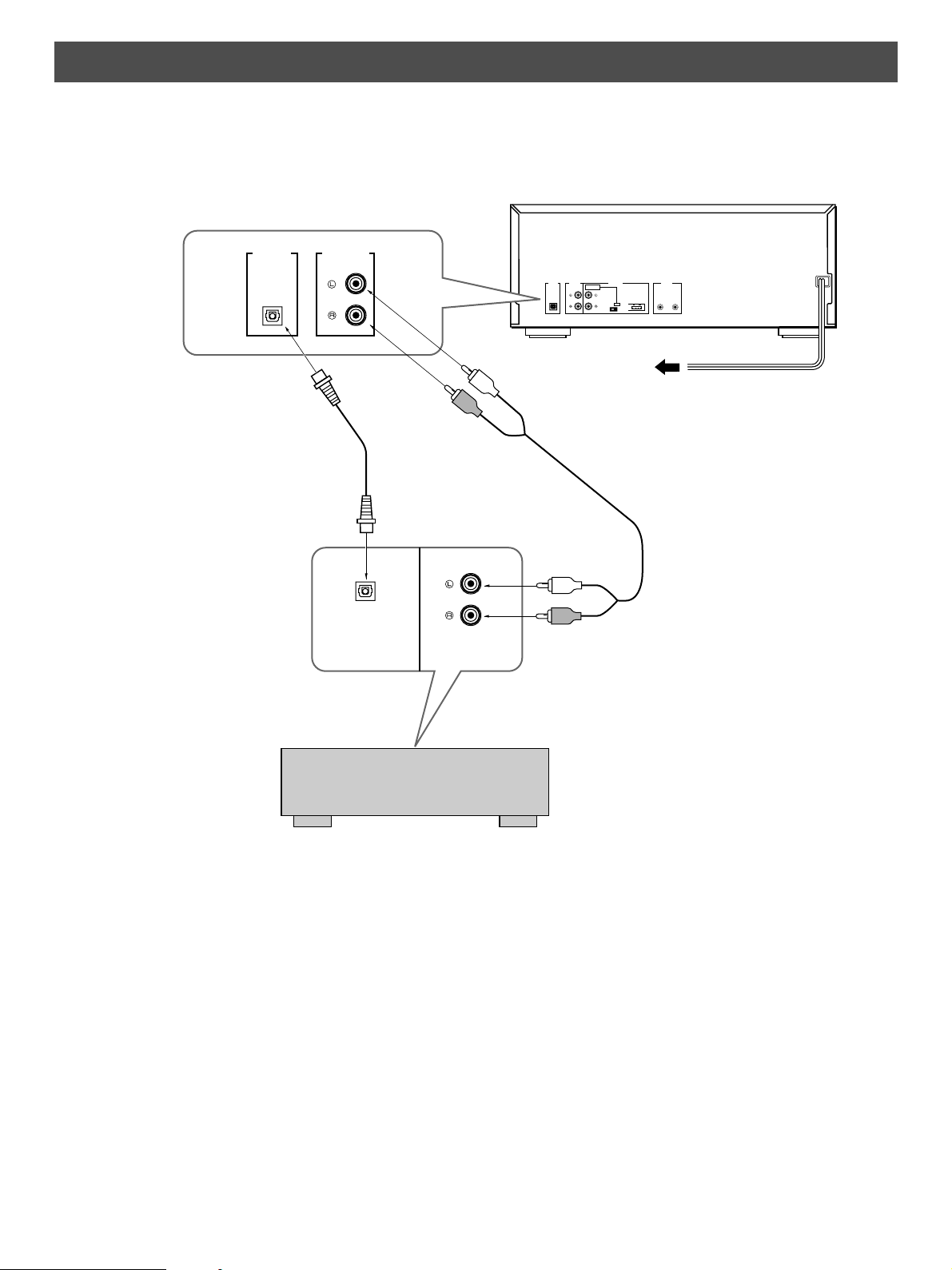
CONNECTIONS
• Never plug in this unit or other components until all connections are completed.
• Connections should be made to the correct input terminals of
the amplifier or other components.
• To connect another unit for relay play, see page 21.
• If the placement of this unit creates interference (noise) in
other equipment, such as a tuner, relocate this unit away
from the affected equipment.
U.S.A model
AUDIO
OPTICAL
2
Optical fiber cable
(not included)
OUT
LINE OUTDIGITAL
1
LINE OUT
2nd CHANGER
INPUT
1
RELAY PLAY REMOTE
CONTROL
2nd MAIN
OUT IN
CONTROL
DIGITAL
AUDIO
OUT
OPTICAL
T o AC outlet
1
Connection cord
(included)
OPTICAL
CDDIGITAL IN
Amplifier
To connect this unit to your amplifier, choose one of the following procedures:
1 When the LINE OUT (analog) terminals of
this unit are used
• Be sure that the left (“L”) and right (“R”) LINE OUT
terminals are connected to the corresponding (left and
right) terminals of the amplifier or other component.
• Connect the “LINE OUT” terminals to the “CD” (or “AUX”)
terminals of the amplifier. If the amplifier does not have
such terminals, use the “T APE PB” terminals. For
additional details concerning these connections, refer to
the operation instructions of the amplifier being used.
• The LINE OUT terminals of this unit are numbered 1.
When connecting this unit with a YAMAHA amplifier or
receiver whose terminals on the rear panel are
numbered as 1, 2, 3, etc., connect the LINE OUT
terminals of this unit to the input terminals numbered 1
on the rear panel of the amplifier or receiver.
4
2 When the DIGITAL OUT terminal of this unit
is used
This unit has a DIGITAL OUT (OPTICAL) terminal on the
rear panel.
• Before using the terminal on the rear panel, remove the
terminal’s cover .
• Make the connection from the terminal to the optical
input terminal of an amplifier or other digital audio
component by using a commercially available optical
fiber cable.
* Use an optical fiber cable that conforms to EIAJ
• Be sure to replace the terminal’s cover when the terminal
on the rear panel is not being used, in order to protect
from dust.
• The terminal can also be connected to the optical input
terminal of a DA T (Digital Audio Tape) deck or MD (Mini
Disc) deck, etc., to record a CD directly.
• The output level of this terminal is not variable.
standards. Other cables might not function correctly .
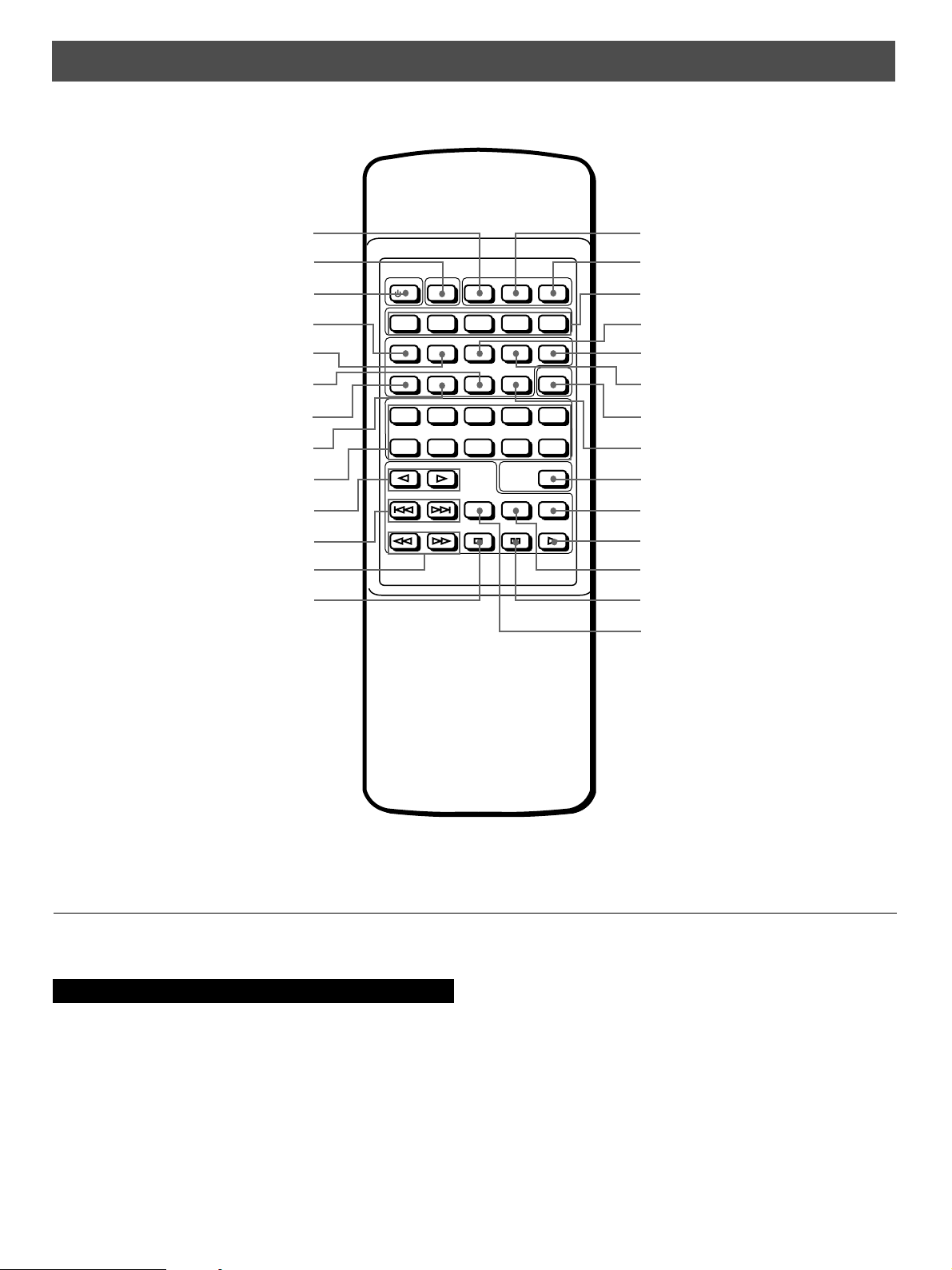
IDENTIFICATION OF COMPONENTS
REMOTE CONTROL TRANSMITTER
English
ALL button (p.8)
ACTIVE button (p.22)
POWER button (p.8)
INTRO button (p.17)
FILE MODE button (p.19)
DISC button (p.9)
FILE EDIT button (p.18)
GROUP EDIT button (p.15)
Number buttons (p.9)
DISC SKIP buttons (p.8)
SKIP buttons (p.9)
SEARCH buttons (p.10)
STOP button (p.8)
POWER ACTIVE ALL PROG +1 DISC
/ I
ABCDE
INTRO FILE MODE TEXT MODE TIME MODE TEXT SRCH
FILE EDIT GROUP EDIT DISC DELETE CAPS
1
67890
DISK SKIP
DISC GROUP
2345
ENTER
SKIP
SEARCH
INDEX REPEAT RANDOM
STOP PAUSE PLAY
PROG (program) button (p.13)
+1 DISC button (p.10)
GROUP (A – E) buttons (p.15)
TEXT MODE button (p.19)
TEXT SRCH (search) button (p.19)
TIME MODE button (p.10)
CAPS (capital letters) button (p.16)
DELETE button (p.14)
ENTER button (p.13)
RANDOM button (p.11)
PLA Y button (p.8)
REPEAT button (p.12)
P AUSE button (p.8)
INDEX button (p.17)
* This manual describes how to operate this unit by using the remote control transmitter. To operate this unit from the front panel,
use the corresponding buttons on the front panel (see page 6).
For Custom Installer
For U.S.A., Canada and Australia models only
REMOTE CONTROL (IN, OUT) terminals
These terminals are used for custom installation system. When this unit is connected to the components for custom installation
system, you can operate this unit with the system remote control.
Connect the REMOTE CONTROL IN terminal of this unit to the output terminal of the central controller for custom installation
system.
By connection the REMOTE CONTROL OUT terminal of this unit to the REMOTE CONTROL IN terminal of the other component,
you can also operate the component with the system remote control. In this way, up to 6 components can be connected in series.
5
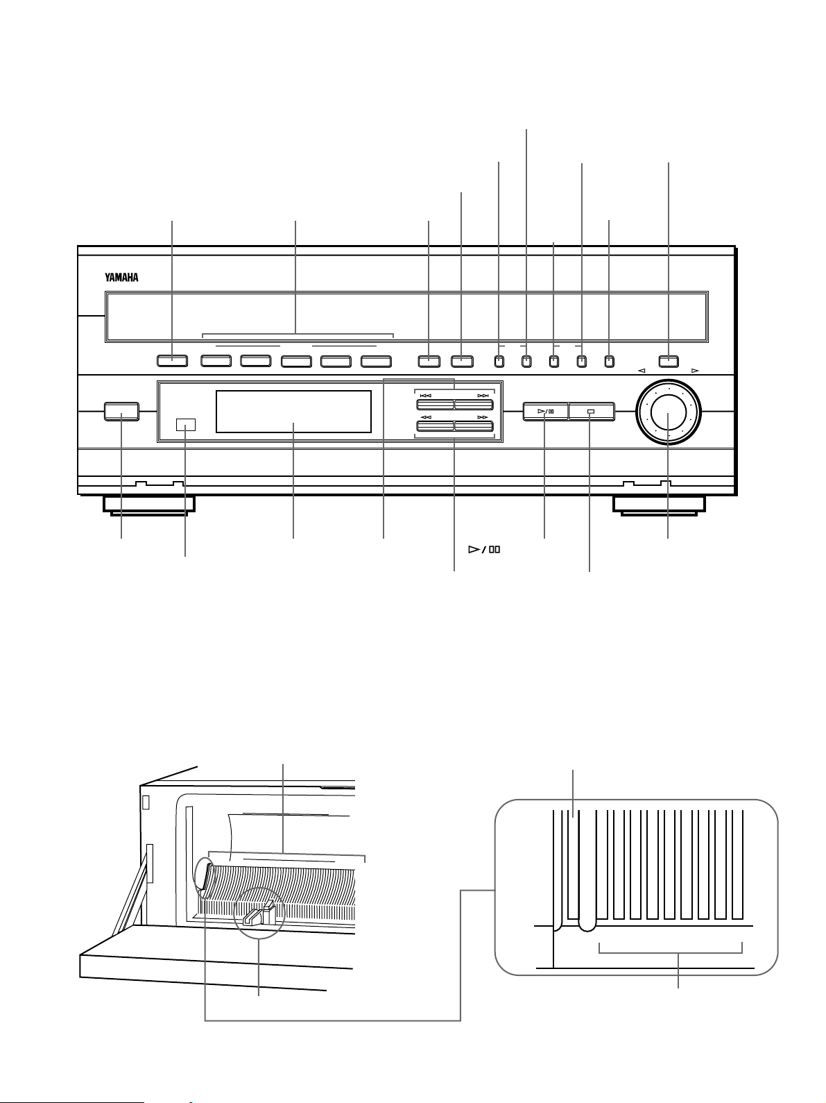
FRONT P ANEL
SINGLE
1
5
0
987
6
43
2
•
TEXT MODE button (p.19)
FILE MODE button (p.19)
GROUP EDIT
button (p.15)
ENTER button (p.13)
+1DISC button (p.10)
STANDBY/ON
STANDBY/ON
switch (p.8)
PROGRAM button (p.13)
GROUP (A – E)
buttons (p.15)
+1DISC A B C D E ALL PROGRAM
Remote control
DISC GROUP
Display panel
SKIP/CURSOR
buttons (p.9)
sensor (p.23)
ALL button
(p.8)
SKIP/CURSOR
SEARCH
SEARCH buttons
(p.10)
FILE TEXT
button (p.8)
FILE
EDIT
button
(p.18)
MODE
EDIT
FILE GROUP
(PLAY/PAUSE)
STOP button
(p.8)
DELETE
button (p.14)
DELETE ENTER
DISC/CHARACTER
JOG dial
(p.9)
* The PLA Y/PAUSE button on the front panel has the functions of both the PLAY button and the PAUSE button on the remote control
transmitter.
DISC SLOT SECTION
For an explanation on how to open the front panel, see page 7.
Disc slots (p.7)
Loader carriage (p.7)
6
Disc slot for single disc play (SINGLE) (p.10)
Slot numbers (p.7)

INSERTING CDS
English
1 Open the front panel, by pulling gently from both ends.
Magnetic
latch
Notes
• Except when inserting or removing discs, keep your hands
out of the unit while the front panel is open. You could be
injured if your hands could become entagled in the
internal mechanism.
• Keep cassette tapes, video cassettes, or floppy discs
away from the magnetic latches.
2 Slide the loader carriage to the desired slot number to
insert a disc.
Disc slots
5
•
Grasp here and slide.
Slot
number
4 Close the front panel gently.
Note
• If you leave the front panel open while a disc is in play,
when the disc is over, the unit will stop.
To remove discs
1 Open the front panel.
2 Slide the loader carriage to the slot of the disc you want
to remove.
3 Press the eject button on the loader carriage.
Loader carriage
Slot No. 0 (SINGLE) is reserved for single disc play
mode.
3 Set the disc on the loader and flip the loader upwards.
With the Label side facing right
Flip this part upward.
Notes
• Do not use 8-cm (3-inch) CDs. Even if you use the
expander rings, the unit could be damaged.
• Do not put anything other than discs in the unit.
Loader carriage
Eject button
CAUTION FOR CARRYING THIS UNIT
When you carry the unit:
1 Press STANDBY/ON and make sure “ST ANDBY”
disappears from the display .
2 Remove all CDs from the unit.
3 Disconnect the power cord from the AC outlet.
Notes
• You can insert and remove discs while playing a disc.
– Do not set a disc in the slot of the disc being played (slot
indicator flashes). The disc in play is returned to its slot
when finished. If there is a disc in the slot of the disc at
play, when the disc is finished, “TAKE OUT” appears in the
display. Remove the disc from the currently playing disc’s
slot.
– Sometimes the front panel cannot be opened while a disc
is playing. In such case, wait a few moments or until the
disc stops playing then try again.
• Insert the CD correctly and avoid abrupt eject button
operation to prevent discs from popping out or falling into the
unit during operation.
7

1
PAUSE
1
67890
2345
ABCDE
POWER ACTIVE ALL PROG +1 DISC
INTRO FILE MODE TEXT MODE TIME MODE TEXT SRCH
DISC GROUP
FILE EDIT GROUP EDIT DISC DELETE CAPS
INDEX REPEAT RANDOM
STOP PAUSE PLAY
ENTER
DISK SKIP
SKIP
SEARCH
/ I
BASIC OPERA TION
1
2
3
1 Turn the power on.
POWER
/ I
“DISC LOADING” appears in the display for a few
seconds. Then, the disc number that was played most
recently appears in the display .
2 Press DISC SKIP repeatedly until the desired disc
number appears in the display.
DISC SKIP
3
The unit plays all discs in the unit from the selected one.
PLAY
To stop play temporarily
To resume play, press P AUSE again (or press PLAY).
* The
button on the front panel can also be used to stop
play temporarily or to resume play.
To stop play completely
STOP
To turn off the unit (standby mode)
Press POWER again.
Note
• To play all the discs in the unit, make sure the “ALL” indicator
appears in the display . If not, press ALL.
In ALL play mode, the unit plays all the discs from the
selected one. Empty disc slots are skipped.
Display information during disc play
12
ALL
8
DISC TRACK
6
11
12
16
17
34
1 Shows the disc number selected or being played.
2 Shows the track number selected or being played.
3 Shows the time. (Refer to “Selecting time displays” on page
10.)
4 Shows the CD track numbers (up to 20). After each track is
5
7
8
9
10
13
14
15
18
19
20
played, its corresponding number disappears so that
remaining track numbers can be seen at a glance.
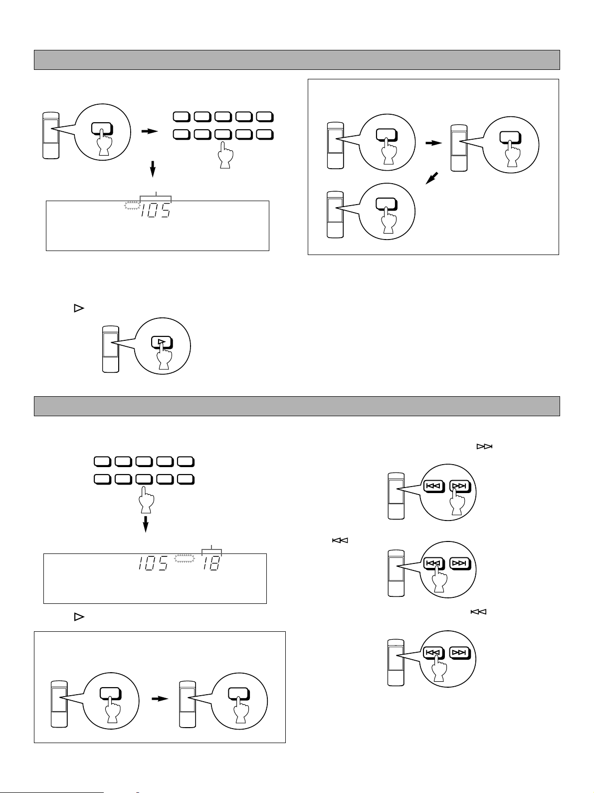
To play a specific disc
SKIP
English
1 Press DISC and the number button of the desired disc.
1
DISC
2345
67890
The selected disc number is displayed.
DISC
You can also select the disc with the JOG dial on the front
panel. In this case, turn the JOG dial on the front panel until
the desired disc number appears in the display .
2 Press to start play.
PLAY
Example: To select disc 105,
press 1, then 0, then 5.
1
5
0
Note
• If there is no disc in the slot you select, the unit plays the disc
in the next slot up which contains a disc.
To play a specific track on the disc
DIRECT PLAY
1 Select a desired track using the number buttons.
1
2345
67890
The selected track number is displayed.
ALL
2 Press to start play.
Example: To select track 25,
press 2, then 5.
* If you enter a number that is higher than the last track
number on the disc, the final track is played.
DISC TRACK
2
3
2
1
8
7
6
13
12
11
18
17
16
5
SKIP PLAY
To skip to a succeeding track, press SKIP once or
repeatedly until the desired track number appears.
SKIP
To skip to the beginning of the current track, press
SKIP
5
4
10
9
15
14
20
19
To skip to a preceding track, press SKIP
once.
SKIP
repeatedly until
the desired track number appears.
Notes
• These operations can also be performed when the unit is in
the pause or stop mode.
• If SKIP is pressed and held, the track number successively
changes to higher numbers (or lower numbers).
9
 Loading...