

Yamaha Audio CDC-675 User Manual
C D C -6 7 5 /5 7 5
NATURAL SOUND COMPACT DISC PLAYER
CHANGEUR AUTOMATIQUE DE COMPACT DISQUES
UCA
OWNER’S MANUAL
CONTENTS
CAUTION............................................................... 4
CONNECTIONS .................................................... 5
IDENTIFICATION OF COMPONENTS.................. 6
BASIC OPERATION .............................................. 8
RANDOM-SEQUENCE PLAY.............................. 13
PROGRAM PLAY................................................. 14
REPEAT PLAY..................................................... 16
INDEX SEARCH.................................................. 16
CD SYNCHRONIZED RECORDING................... 17
TRACK PROGRAMMING FOR RECORDING
TO TAPE ............................. 18
AUTOMATIC SEARCHING FOR THE PEAK
LEVEL ON A DISC ..............21
NOTES ABOUT THE REMOTE CONTROL
TRANSMITTER ................................................... 22
TIMER PLAY ........................22
NOTES ABOUT HANDLING COMPACT
DISCS.................................................................. 23
TROUBLESHOOTING......................................... 24
SPECIFICATIONS ............................................... 24
for CDC-675 only
for CDC-675 only
for CDC-675 only
MODE D’EMPLOI
TABLE DES MATIERES
ATTENTION......................................................... 26
CONNEXIONS..................................................... 27
IDENTIFICATION DES COMPOSANTS.............. 28
FONCTIONNEMENT DE BASE .......................... 30
LECTURE EN SÉQUENCE ALÉATOIRE............ 35
LECTURE PROGRAMMÉE................................. 36
LECTURE REPETÉE .......................................... 38
RECHERCHE D’INDEX....................................... 38
ENREGISTREMENT SYNCHRONISE D’UN
COMPACT DISQUE
PROGRAMMATION DES PLAGES POUR
ENREGISTREMENT SUR CASSETTE
CDC-675 seulement
RECHERCHE AUTOMATIQUE DU NIVEAU DE
CRÊTE D’UN DISQUE
CDC-675 seulement
REMARQUES CONCERNANT LA
TELECOMMANDE............................................... 44
LECTURE COMMANDÉE PAR
PROGRAMMATEUR
............................................. 39
...................................... 40
.......................................43
CDC-675 seulement
REMARQUES CONCERNANT LA MANIPULATION
DES DISQUES .................................................... 45
DEPISTAGE DE PANNES................................... 46
CARACTERISTIQUES TECHNIQUES................ 46
.......................................44
CAUTION
RISK OF ELECTRIC SHOCK
DO NOT OPEN
CAUTION: TO REDUCE THE RISK OF
ELECTRIC SHOCK, DO NOT REMOVE
COVER (OR BACK). NO USER-SERVICEABLE
PARTS INSIDE. REFER SERVICING TO
QUALIFIED SERVICE PERSONNEL.
IMPORTANT!
Please record the serial number of this unit
in the space below.
Model:
Serial No.:
The serial number is located on the rear of
the unit.
Retain this Owner’s Manual in a safe place
for future reference
SAFETY INSTRUCTIONS
Explanation of Graphical Symbols
•
The lightning flash with arrowhead
symbol, within an equilateral triangle,
is intended to alert you to the
presence of uninsulated “dangerous
voltage” within the product’s
enclosure that may be of sufficient
magnitude to constitute a risk of
electric shock to persons.
The exclamation point within an
equilateral triangle is intended to alert
you to the presence of important
operating and maintenance
(servicing) instructions in the
literature accompanying the
appliance.
WARNING
TO REDUCE THE RISK OF FIRE OR
ELECTRIC SHOCK, DO NOT EXPOSE THIS
UNIT TO RAIN OR MOISTURE.
1 Read Instructions – All the safety and operating
instructions should be read before the unit is operated.
2 Retain Instructions – The safety and operating instructions
should be retained for future reference.
3 Heed Warnings – All warnings on the unit and in the
operating instructions should be adhered to.
4 Follow Instructions – All operating and other instructions
should be followed.
5 Water and Moisture – The unit should not be used near
water – for example, near a bathtub, washbowl, kitchen
sink, laundry tub, in a wet basement, or near a swimming
pool, etc.
6 Carts and Stands – The unit should be used only with a
cart or stand that is recommended by the manufacturer.
6A A unit and cart combination should be
moved with care. Quick stops, excessive
force, and uneven surfaces may cause the
unit and cart combination to overturn.
7 Wall or Ceiling Mounting – The unit should
be mounted to a wall or ceiling only as
recommended by the manufacturer.
8 Ventilation – The unit should be situated so that its
location or position does not interfere with its proper
ventilation. For example, the unit should not be situated
on a bed, sofa, rug, or similar surface, that may block the
ventilation openings; or placed in a built-in installation,
such as a bookcase or cabinet that may impede the flow
of air through the ventilation openings.
9 Heat – The unit should be situated away from heat
sources such as radiators, stoves, or other appliances that
produce heat.
10 Power Sources – The unit should be connected to a
power supply only of the type described in the operating
instructions or as marked on the unit.
11 Power-Cord Protection – Power-supply cords should be
routed so that they are not likely to be walked on or
pinched by items placed upon or against them, paying
particular attention to cords at plugs, convenience
receptacles, and the point where they exit from the unit.
12 Cleaning – The unit should be cleaned only as
recommended by the manufacturer.
13 Nonuse Periods – The power cord of the unit should be
unplugged from the outlet when left unused for a long
period of time.
14 Object and Liquid Entry – Care should be taken so that
objects do not fall into and liquids are not spilled into the
inside of the unit.
15 Damage Requiring Service – The unit should be serviced
by qualified service personnel when:
A. The power-supply cord or the plug has been
damaged; or
B. Objects have fallen, or liquid has been spilled into the
unit; or
C. The unit has been exposed to rain; or
D. The unit does not appear to operate normally or
exhibits a marked change in performance; or
E. The unit has been dropped, or the cabinet damaged.
16 Servicing – The user should not attempt to service the unit
beyond those means described in the operating
instructions. All other servicing should be referred to
qualified service personnel.
17 Power Lines – An outdoor antenna should be located
away from power lines.
18 Grounding or Polarization – Precautions should be taken
so that the grounding or polarization is not defeated.
2
FCC INFORMATION (for US customers only)
English
1. IMPORTANT NOTICE : DO NOT MODIFY THIS UNIT!
This product, when installed as indicated in the
instructions contained in this manual, meets FCC
requirements. Modifications not expressly approved by
Yamaha may void your authority, granted by the FCC, to
use the product.
2. IMPORTANT : When connecting this product to
accessories and/or another product use only high quality
shielded cables. Cable/s supplied with this product
MUST be used. Follow all installation instructions.
Failure to follow instructions could void your FCC
authorization to use this product in the USA.
3. NOTE : This product has been tested and found to
comply with the requirements listed in FCC Regulations,
Part 15 for Class “B” digital devices. Compliance with
these requirements provides a reasonable level of
assurance that your use of this product in a residential
environment will not result in harmful interference with
other electronic devices.
This equipment generates/uses radio frequencies and, if
not installed and used according to the instructions
found in the users manual, may cause interference
harmful to the operation of other electronic devices.
Compliance with FCC regulations does not guarantee that
interference will not occur in all installations. If this product
is found to be the source of interference, which can be
determined by turning the unit “OFF” and “ON”, please try
to eliminate the problem by using one of the following
measures:
Relocate either this product or the device that is being
affected by the interference.
Utilize power outlets that are on different branch (circuit
breaker or fuse) circuits or install AC line filter/s.
In the case of radio or TV interference, relocate/reorient the
antenna. If the antenna lead-in is 300 ohm ribbon lead,
change the lead-in to coaxial type cable.
If these corrective measures do not produce satisfactory
results, please contact the local retailer authorized to
distribute this type of product. If you can not locate the
appropriate retailer, please contact Yamaha Electronics
Corp., U.S.A. 6660 Orangethorpe Ave, Buena Park, CA
90620.
The above statements apply ONLY to those products
distributed by Yamaha Corporation of America or its
subsidiaries.
WARNING
CAUTION
Use of controls or adjustments or performance of
procedures other than those specified herein may result in
hazardous radiation exposure.
DANGER
Invisible laser radiation when open and interlock failed or
defeated.
Avoid direct exposure to beam.
Laser Diode Properties
• Material: GaAlAs
• Wavelength: 780nm
• Emission Duration: continuous
• Laser Output: max. 44.6µW*
* This output is the value measured at a distance of about
200mm from the objective lens surface on the Optical Pickup Block.
We Want You Listening For A Lifetime
YAMAHA and the Electronic Industries Association’s
Consumer Electronics Group want you to get the most out of
your equipment by playing it at a safe level. One that lets the
sound come through loud and clear without annoying blaring or
distortion – and, most importantly, without affecting your
sensitive hearing. Since hearing damage from loud sounds is
As the laser beam used in this compact disc player is harmful
to the eyes, do not attempt to disassemble the cabinet. Refer
servicing to qualified personel only.
To avoid electrical shock, do not open the unit. Refer
servicing to qualified personnel only.
DANGER: The use of optical instrument with this product will
increase eye hazard.
For Canadian Customers
To prevent electric shock, match wide blade of plug to wide
slot and fully insert.
This Class B digital apparatus complies with Canadian ICES-
003.
often undetectable until it is too late, YAMAHA
and the Electronic Industries Association’s
Consumer Electronics Group recommend you to
avoid prolonged exposure from excessive
volume levels.
3
CAUTION: READ THIS BEFORE OPERATING YOUR UNIT
1 To ensure the finest performance, please read this manual
carefully. Keep it in a safe place for future reference.
2 Install your unit in a cool, dry, clean place, and in a
horizontal and stable position – away from windows, heat
sources, vibration, dust, moisture, or cold. To avoid
humming sounds, locate the unit away from other
electrical appliances, motors, and transformers. To
prevent fire or electrical shock, do not expose to rain and
water.
3 Do not operate the unit upside-down. It may overheat,
possibly causing damage.
4 Never open the cabinet. If a foreign object drops into the
set, contact your dealer.
5 Do not use force on switches, knobs or cords.
6 Do not attempt to clean the unit with chemical solvents;
this might damage the finish. Use a clean, dry cloth.
7 Be sure to read the “TROUBLESHOOTING” section on
common operating errors before concluding that your unit
is faulty.
8 Do not place another component on top of this unit,
because to do so will discolor or damage the surface of
the unit.
9 To prevent damage by lightning, disconnect the power
cord from the household AC outlet during an electrical
storm.
10 When disconnecting the power cord from the household
AC outlet, grasp the plug; do not pull the cord.
CAUTION FOR CARRYING THIS UNIT
Be sure not to carry or tip this unit with discs remaining in it.
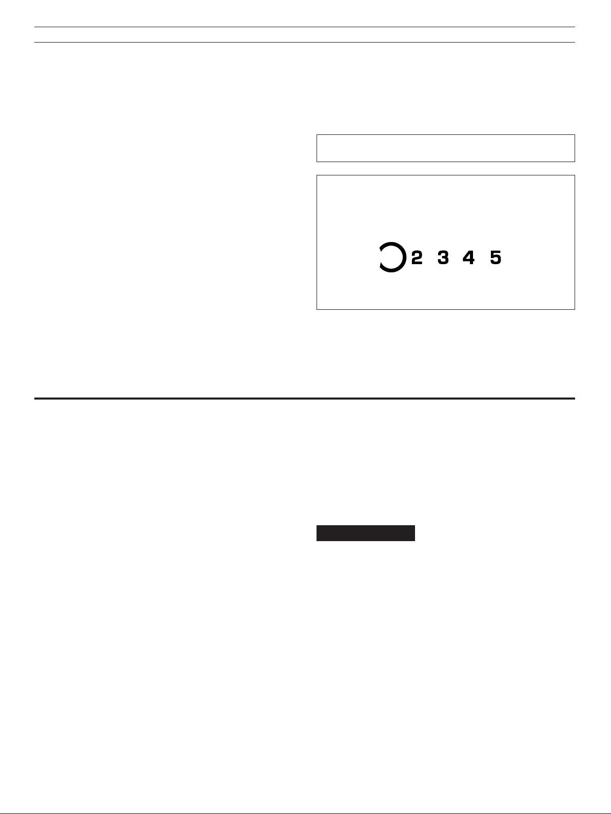
CAUTION FOR MOVING THIS UNIT
When moving this unit, first remove all discs from the disc tray and
close the tray by pressing the OPEN/CLOSE button. After you
confirm that the display lights up as shown below, switch off the
power by pressing the POWER switch, and then disconnect the
power plug from the AC outlet.
Never switch off the power untill the display lights up as above,
otherwise this unit will break down during moving because the
internal mechanism is not locked.
FEATURES
●
5-Disc Carousel Auto-changer
●
Full Opening Disc Tray for Changing 5
Discs at a Time
●
PLAYXCHANGE; Disc Changing
Capability while Playing Another
●
CD TEXT Compatibility
●
Random Access Programmable Play
●
Random-Sequence Play
●
Single Track/Entire Disc/All Disc Repeat
Play
●
Adjustable Display Brightness
●
Disc Scanning Capability Useful for Disc
Searching or Disc Checking
●
CD Synchronized Recording with a
Compatible YAMAHA Tape Deck
●
Optical Digital Output
CDC-675 only
●
Automatic Programming for Recording to
Tape
●
Timer Play Option
●
Automatic Peak Level Searching
Capability
●
Adjusting the Output Level
●
Remote Control Capability
4
●
PHONES jack
D IG IT A L INC D
O P T IC A L
O P T IC A L
D I GI T A L
A U D I O
O U T
L IN E O U T
1
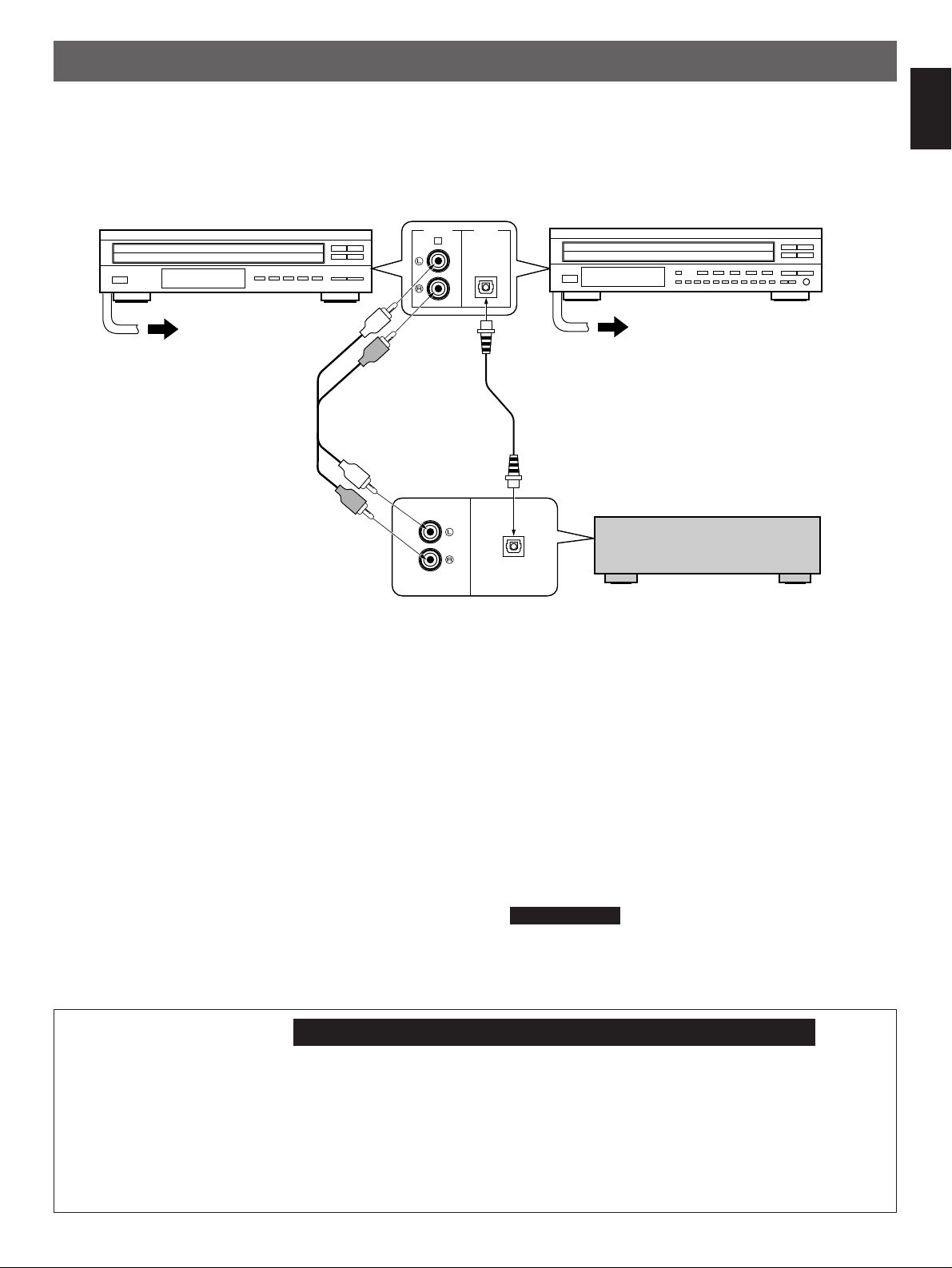
CONNECTIONS
Never plug in this unit and other components until all connections are completed.
●
Before making any connections, switch OFF the power to
the unit and the amplifier or other components.
●
Connections should be made to the correct input terminals
of the amplifier or other components.
CDC-575 CDC-675
●
If the placement of this unit causes noise in other equipment,
such as a tuner, separate them from each other.
English
To AC outlet
Optical fiber cable
➋
(not included)
Connection cord
➊
(included)
Choose one of the ways listed below to connect this unit to your amplifier.
When the LINE OUT (analog) terminals of this
unit are used (
●
Be sure that the left (“L”) and right (“R”) LINE OUT terminals
are connected to the corresponding (left and right) terminals
of the amplifier or other components.
●
Connect the “LINE OUT” terminals to the “CD” (or “AUX”)
terminals of the amplifier. If the amplifier does not have
such terminals, use the “TAPE PB” terminals. For additional
details concerning these connections, refer to the operation
instructions for the amplifier being used.
●
The LINE OUT terminals of this unit are numbered 1. When
connecting this unit with a YAMAHA amplifier or receiver
whose terminals on the rear panel are numbered as 1, 2,
3, etc., connect the LINE OUT terminals of this unit to the
input terminals numbered 1 on the rear of the amplifier or
receiver.
➊
)
When the DIGITAL AUDIO OUT (OPTICAL)
terminal of this unit is used (
●
Before using this terminal, remove the terminal’s cover by
pulling it.
●
Make the connection from this terminal to the optical input
terminal of an amplifier by using a commercially available
optical fiber cable.
* Be sure to use a high quality optical fiber cable. Other
cables might not function correctly.
●
This terminal can also be connected to the optical input
terminal of a digital audio tape deck (DAT), etc. to record CD
onto tape directly.
●
Be sure to attach the terminal cover when this terminal is not
being used in order to protect the terminal from dust.
●
CDC-675 only
Set the level of signals output into an amplifier to max. by
using the OUTPUT LEVEL buttons.
To AC outlet
Amplifier
➋
)
For Custom Installer
For U.S.A., Canada and Australia models of CDC-675 only
REMOTE CONTROL (IN, OUT) terminals
These terminals are used for custom installation system.
When this unit is connected to the components for custom
installation system, you can operate this unit with the
system remote control.
Connect the REMOTE CONTROL IN terminal of this unit to
the output terminal of the central controller for custom
installation system.
By connecting the REMOTE CONTROL OUT terminal of
this unit to the REMOTE CONTROL IN terminal of the other
component, you can also operate it with the system remote
control. In this way, up to 6 components can be connected
in series.
5
P O W ER
5
S K IP /S E AR C H
+1 0
1
2 3 4 5 6 7 8 9 0
P RO G
P LA Y X C H A N GE
O PE N /C L O SE
O U TP U T LE V E L
P HO N E S
D IS C
N A T U RA L S O UN D C O M P A C T D IS C P LA Y E R
PE A K
/
1 2 3 4
+–
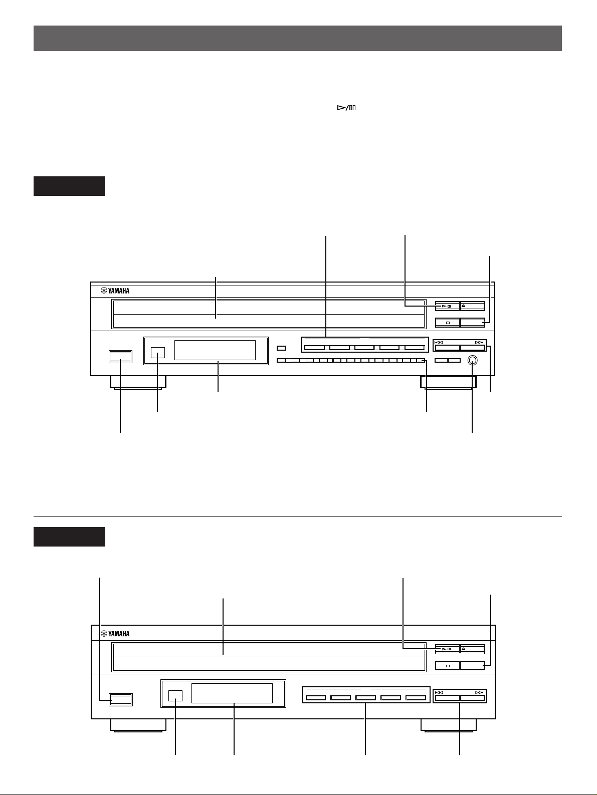
IDENTIFICATION OF COMPONENTS
N A T U RA L S O UN D C O M P A C T D IS C P LA Y E R
P O W ER
5
D IS C
1 2 3 4
S K IP /S E AR C H
P LA Y X C H A N GE
O PE N /C L O SE
/
* ( ) indicates the page number on which the control and its function are best described.
FRONT PANEL
* The control functions on the main unit and on the remote
control transmitter are virtually identical, with the exceptions
below.
CDC-675
Disc tray (p. 8)
* The (PLAY/PAUSE) button on the main unit has both
the functions of the PLAY button and the PAUSE button on
the remote control transmitter.
* The SKIP/SEARCH buttons on the main unit have both the
functions of the SKIP button and the SEARCH button on the
remote control transmitter.
Play/Pause button (p. 8, 9)DISC-select buttons (p. 8)
PLAYXCHANGE button (p. 9)
Display panel
Remote control sensor (p. 22)
PEAK button (p. 21)
SKIP/SEARCH
buttons (p. 10)
POWER switch (p. 8) PHONES jack (p. 12)
CDC-575
POWER switch (p. 8)
Disc tray (p. 8)
Play/Pause button (p. 8, 9)
PLAYXCHANGE button (p. 9)
Display panel DISC-select buttons (p. 8) SKIP/SEARCH buttons (p. 10)Remote control sensor (p. 22)
6
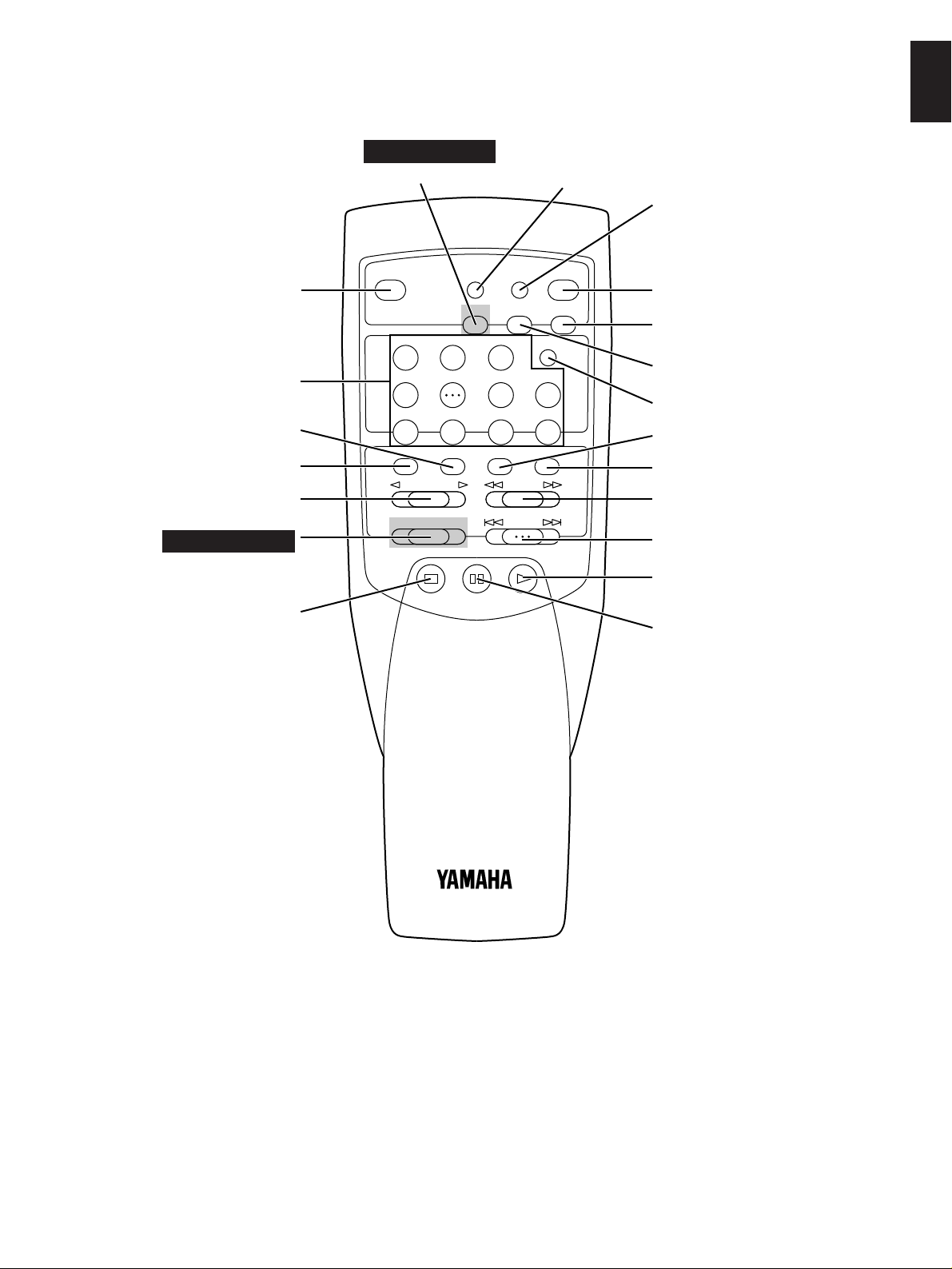
REMOTE CONTROL TRANSMITTER
T A P E C LE A R
S Y N C H R O
P R O G
D IM M E R
O P E N /
C LO S E
S T O P P A U S E P L A Y
21 3
IN D E X
87 9 0
54 6 +I0
R E P E A T R A N D O MM O D ED IS C S C A N
S E A R C H
S K IP
O U T P U T L E V E L
– +
D IS C S K I P
T E X T /
T IM E
TAPE button (p. 18)
English
CDC-675 only
DIMMER button (p. 12)
TEXT/TIME display mode-select
button (p. 11)
SYNCHRO button (p. 17)
Numeric buttons (p. 10)
Disc play MODE-select button
(p. 8)
DISC SCAN button (p. 11)
DISC SKIP button (p. 8)
CDC-675 only
OUTPUT LEVEL button (p. 12)
STOP button (p. 9)
OPEN/CLOSE button (p. 8)
PROG button (p. 14)
CLEAR button (p. 15)
INDEX button (p. 16)
REPEAT button (p. 16)
RANDOM button (p. 13)
SEARCH button (p. 10)
SKIP button (p. 10)
PLAY button (p. 8)
PAUSE button (p. 9)
Parts in the shaded areas are provided for CDC-675 only.
7
P O W E R
O P E N /
C LO S E
O P E N /
C LO S E
P L A Y
P L A Y
This manual describes how to operate this unit by using the remote control transmitter.
P OW E R
N A TU R A L S O U N D C O M P
21
S Y NC H R O
3
IN D E X
P RO GC LE A R
87 9 0
54 6 +I0
D IM M E R
O PE N /
C LO S E
T EX T /
T IM E
R EP E AT R AN D O MM O D ED IS C S C A N
S EA R C H
S KI P
S TO P P AU S E P LA Y
D IS C S K IP
5
2, 3
5
4
2 3 4
D I S C
21
T AP E
S Y NC H R O
3
IN D E X
P RO GC LE A R
87 9 0
54 6 +I0
D IM M E R
O PE N /
C LO S E
T EX T /
T IM E
R EP E AT R AN D O MM O D ED IS C S C A N
S EA R C H
S KI P
O UT P U T LE V EL
– +
S TO P P AU S E P LA Y
D IS C S K IP
2, 3
5
4
5
M O D E
D IS C S K I P
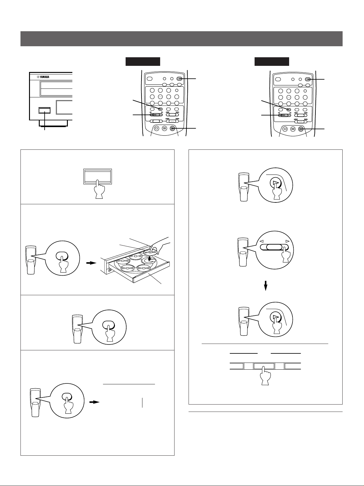
To operate this unit on the front panel, use the corresponding buttons on the front panel.
BASIC OPERATION
CDC-675
1
1 Turn the power on.
2 Open the disc tray and load discs.
Use the disc guides to align the discs correctly in the
tray.
Label side
upward
CDC-575
5 Start play from the first track of the disc 1.
* If necessary, select a desired disc by using the DISC SKIP
button or a DISC-select button.
3 Close the disc tray.
4 Select a desired disc play mode (1DISC or 5DISCS)
confirming it on the display.
1DISC
5DISCS
Shows the selected disc
sequence.
“1DISC” mode: The unit will play a designated disc only.
“5DISCS” mode: The unit will play all discs on the tray in
8
mode.
Disc tray
(On the front panel)
To turn off the power
Press the POWER switch again.
 Loading...