

Yamaha Audio AX-V401 User Manual

A X-V4 01
Natural Sound Stereo Integrated Amplifier
Préampli/ampli de puissance stéréo de la série “Natural Sound”
Natural Sound Stereo-Verstärker
Natural Sound Integrerad Stereo Förstärkare
Amplificatore integrato stereo a Suono Naturale
Amplificador integrado estéreo de Sonido Natural
Natural Sound Geïntegreerde Stereo Versterker
S
OWNER’S MANUAL
MODE D’EMPLOI
BEDIENUNGSANLEITUNG
BRUKSANVISNING
MANUALE DI ISTRUZIONI
MANUAL DE INSTRUCCIONES
GEBRUIKSAANWIJZING
SUPPLIED ACCESSORIES
ACCESSOIRES FOURNIS
MITGELIEFERTE ZUBEHÖRTEILE
MEDFÖLJANDE TILLBEHÖR
ACCESSORI IN DOTAZIONE
ACCESORIOS INCLUIDOS
BIJGELEVERDE ACCESSOIRES
●
After unpacking, check that the following parts are contained.
●
Après le déballage, vérifier que les pièces suivantes sont incluses.
●
Nach dem Auspacken überprüfen, ob die folgenden Teile vorhanden sind.
●
Kontrollera effer det apparaten packats upp att följande delar finns med.
●
Disimballato l’apparecchio, controllate di possedere tutte le parti menzionate.
●
Desembale el aparato y verifique que los siguientes accesorios están en la caja.
●
Controleer na het uitpakken of de volgende onderdelen voorhanden zijn.
●
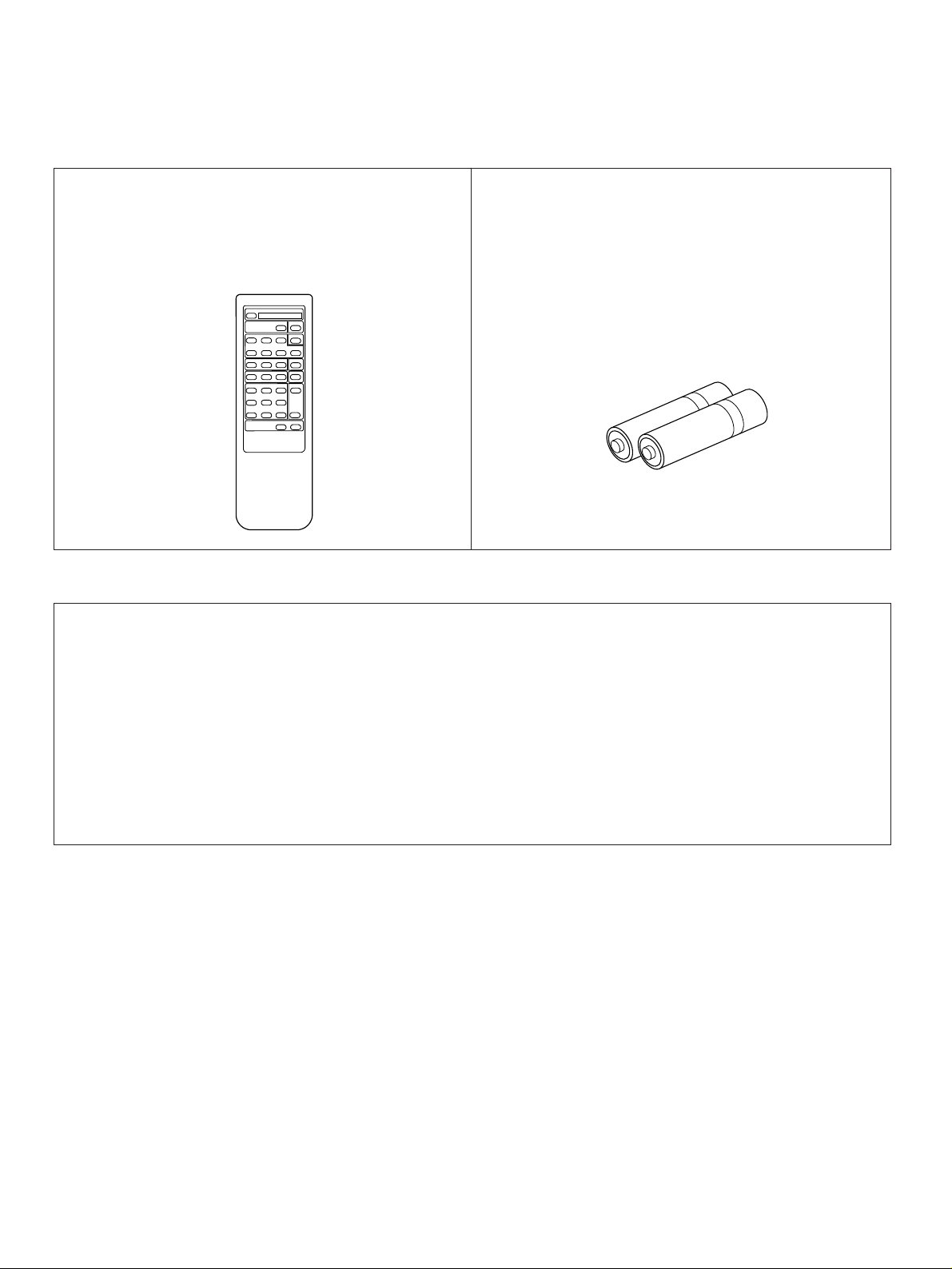
Remote Control Transmitter
●
Emetteur de télécommande
●
Fernbedienungsgeber
●
Fjärrkontrollsändare
●
Trasmittente del telecomando
●
Transmisor del control remoto
●
Afstandbediening
●
Batteries (size AA, R6, UM-3)
●
Piles (taille AA, R6, UM-3)
●
Batterien (größ AA, R6, UM-3)
●
Batterier (storlek AA, R6, UM-3)
●
Batterie (taglia AA, R6, UM-3)
●
Pilas (tamaño AA, R6, UM-3)
●
Batterijen (maat AA, R6, UM-3)
This product complies with the radio frequency interference requirements of the Council Directive 82/499/EEC and/or
87/308/EEC.
Cet appareil est conforme aux prescriptions de la directive communautaire 87/308/CEE.
Diese Geräte entsprechen der EG-Richtlinie 82/499/EWG und/oder 87/308/EWG.
Dette apparat overholder det gaeldende EF-direktiv vedrørende radiostøj.
Questo apparecchio è conforme al D.M.13 aprile 1989 (Direttiva CEE/87/308) sulla soppressione dei radiodisturbi.
Este producto está de acuerdo con los requisitos sobre interferencias de radio frequencia fijados por el Consejo Directivo
87/308 CEE.
Dit product voldoet aan de EEG normen betreffende radio-frekwentie storingen 82/499/EEG en/of 87/308/EEG.
2
Thank you for selecting this YAMAHA stereo amplifier.
FEATURES CONTENTS
•
55W + 55W (8Ω) RMS Output Power, 0.04% THD,
20–20,000 Hz
• High Dynamic Power, Low Impedance Drive
Capability
• Continuously Variable Loudness Control
• Source Direct Switch to Reproduce the Purest
Source Sound
• Video Signal Input/Output Capability
• Remote Control Capability
Supplied Accessories .....................................................2
Caution ...........................................................................3
Connections ...................................................................4
Operations ......................................................................6
Remote Control Transmitter ...........................................9
Notes about the Remote Control Transmitter .........................10
Troubleshooting ............................................................11
Specifications ...............................................................12
CAUTION: READ THIS BEFORE OPERATING YOUR UNIT.
ENGLISH
1. To assure the finest performance, please read this manual
carefully. Keep it in a safe place for future reference.
2. Install this unit in a cool, dry, clean place – away from windows,
heat sources, sources of excessive vibration, dust, moisture and
cold. Avoid sources of humming (transformers, motors). To
prevent fire or electrical shock, do not expose the unit to rain or
water.
3. Never open the cabinet. If something drops into the set, contact
your dealer.
4. Do not use force on switches, controls or connection wires. When
moving the unit, first disconnect the power plug and the wires
connected to other equipment. Never pull the wire itself.
5. The openings on the cabinet assure proper ventilation of the unit.
If these openings are obstructed, the temperature inside the
cabinet will rise rapidly and eventually damage the circuits.
Therefore, avoid placing objects against these openings and do
not install the unit where the flow of air through the ventilation
openings could be impeded.
6. Always set the VOLUME control to “–
audio source play: increase the volume gradually to an
appropriate level after the play has been started.
” before starting the
∞
7. Do not attempt to clean the unit with chemical solvents; this might
damage the finish. Use a clean, dry cloth.
8. Be sure to read the “TROUBLESHOOTING” section regarding
common operating errors before concluding that the unit is faulty.
9. When not planning to use this unit for long periods of time (ie.,
vacation, etc.), disconnect the AC power plug from the wall outlet.
10.To prevent lightning damage, disconnect the AC power plug and
disconnect the antenna cable when there is an electrical storm.
11.Grounding or polarization – Precautions should be taken so that
the grounding or polarization of an appliance is not defeated.
12.AC outlet
Do not connect audio equipment to the AC outlet on the rear panel
if that equipment requires more power than the outlet is rated to
provide.
13.Voltage Selector (General Model only)
The voltage selector on the rear panel of this unit must be set
for your local main voltage BEFORE plugging into the AC
main supply.
Voltages are 110/120/220/240 V AC, 50/60 Hz.
IMPORTANT
Please record the serial number of this unit in the space below.
Serial No.:
The serial number is located on the rear of the unit.
Retain this Owner’s Manual in a safe place for future reference.
WARNING
TO REDUCE THE RISK OF FIRE OR ELECTRIC SHOCK, DO
NOT EXPOSE THIS UNIT TO RAIN OR MOISTURE.
CAUTION (FOR CANADA MODEL)
TO PREVENT ELECTRIC SHOCK, MATCH WIDE BLADE OF
PLUG TO WIDE SLOT, AND FULLY INSERT.
FOR CANADIAN CUSTOMER
THIS DIGITAL APPARATUS DOES NOT EXCEED THE “CLASS B”
LIMITS FOR RADIO NOISE EMISSIONS FROM DIGITAL
APPARATUS SET OUT IN THE RADIO INTERFERENCE
REGULATION OF THE CANADIAN DEPARTMENT OF
COMMUNICATIONS.
CAUTION
The power switch does not disconnect the complete apparatus from
the mains line.
Special Instructions for U.K. Model
IMPORTANT
THE WIRES IN THE MAINS LEAD ARE COLOURED IN
ACCORDANCE WITH THE FOLLOWING CODE:
Blue: NEUTRAL
Brown: LIVE
As the colours of the wires in the mains lead of this apparatus may
not correspond with the coloured markings identifying the terminals
in your plug, proceed as follows:
The wire which is coloured BLUE must be connected to the terminal
which is marked with the letter N or coloured BLACK. The wire
which is coloured BROWN must be connected to the terminal which
is marked with the letter L or coloured RED. Making sure that
neither core is connected to the earth terminal of the three pin plug.
3
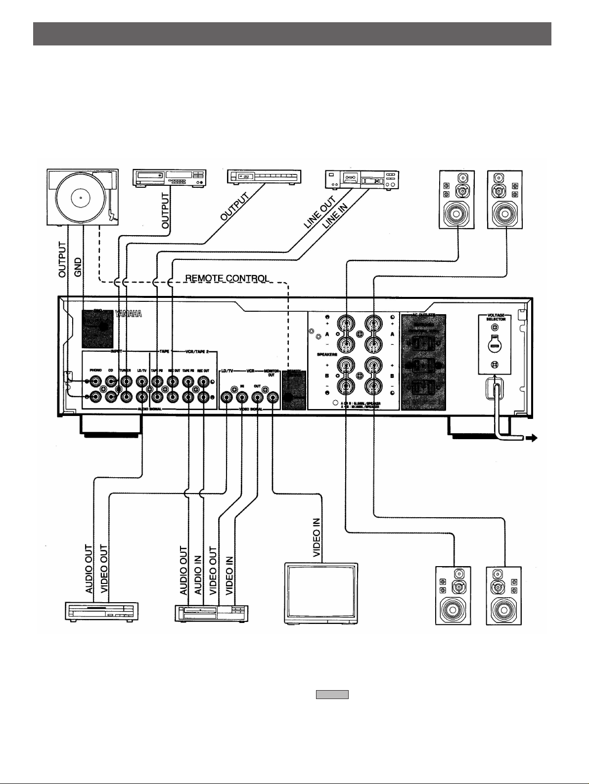
CONNECTIONS
• Before attempting to make any connections to or from this unit, be sure to first switch OFF the power to this unit and to any other
components to which connections are being made.
• When making connections between this unit and other components, be sure all connections are made correctly, that is to say L
(left) to L, R (right) to R, “+” to “+” and “–” to “–”. Also, refer to the owner’s manual for each component to be connected to this
unit.
Turntable Compact disc player Tuner
Tape deck 1 Speakers A
Right
(General model)
Left
LD player, TV tuner, etc.
Video cassette
recorder or
tape deck 2
To AC outlet
Right Left
Monitor TV Speakers B
* : Refer to “ABOUT THE ACCESSORY
TERMINALS” on page 5.
* If a tape deck is connected to the VCR/TAPE 2 (AUDIO
SIGNAL) terminals, there is no connection to the VCR
(VIDEO SIGNAL) terminals.
4
CONNECTING SPEAKERS
2
3
1
Connect the SPEAKERS terminals to your speakers with wire
of the proper gauge, cut to be as short as possible. If the
connections are faulty, no sound will be heard from the
speakers. Make sure that the polarity of the speaker wires is
correct, that is, + and – markings are observed. If these wires
are reversed, the sound will be unnatural and will lack bass.
Do not let the bare speaker wires touch each other and do
not let them touch the metal parts of this unit as this could
damage this unit and/or speakers.
●
One or two speaker systems can be connected to this unit.
If you connect only one speaker system, connect it to either
the SPEAKERS A or B terminals.
●
Use speakers with the specified impedance shown on the
rear of this unit.
How to Connect:
Red: positive (+)
Black: negative (–)
●
Banana Plug connections are also possible (except for
Scandinavian models). Simply insert the Banana Plug
connector into the corresponding terminal.
ENGLISH
Unscrew the knob.
➀
Insert the bare wire.
➁
[Remove approx. 5mm
(1/4”) insulation from
the speaker wires.]
Tighten the knob and
➂
secure the wire.
ABOUT THE ACCESSORY TERMINALS
AC OUTLETS
(Europe and General models).............3 SWITCHED OUTLETS
(Australia and U.K. models)...................1 SWITCHED OUTLET
Use these to connect the power cords from your components
to this unit.
The power to the SWITCHED outlets is controlled by this unit’s
POWER switch or the provided remote control transmitter’s
POWER key. These outlets will supply power to any
component whenever this unit is turned on.
The maximum power (total power consumption of
components) that can be connected to the SWITCHED AC
OUTLETS is 100 watts (200 watts for General model only).
REMOTE CONTROL (PHONO) connector
If you have a YAMAHA turntable with the mark, connect it
to this connector by using the cable provided with the
turntable. This connection allows you to control the turntable
from the provided remote control transmitter.
GND terminal (For turntable use)
Connecting the ground wire of the turntable to this terminal will
minimize hum, but in some cases better results may be
obtained with the ground wire disconnected.
5
 Loading...