


AX-496/396
STEREO AMPLIFIER
AMPLIFICATEUR STEREO
G B
OWNER’S MANUAL
MODE D’EMPLOI
BEDIENUNGSANLEITUNG
BRUKSANVISNING
MANUALE DI ISTRUZIONI
MANUAL DE INSTRUCCIONES
GEBRUIKSAANWIJZING
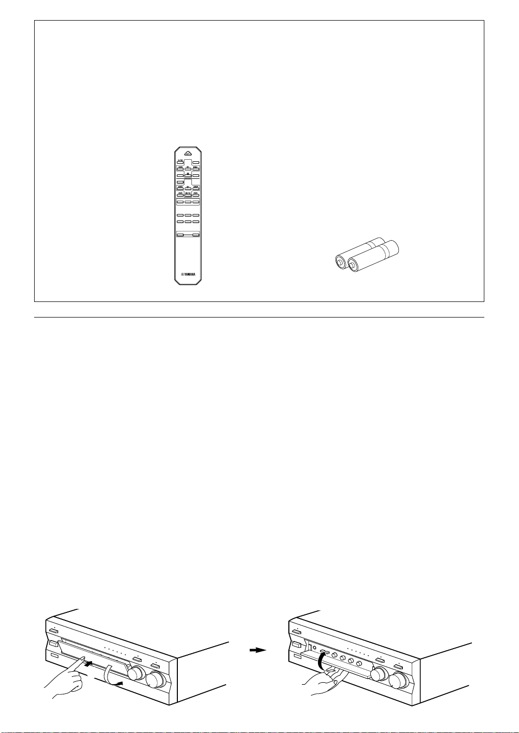
UNPACKING After unpacking, check that the following items are contained. DEBALLAGE Après le déballage, vérifier que les pièces suivantes sont incluses. AUSPACKEN Nach dem Auspacken überprüfen, ob die folgenden Teile vorhanden sind. UPPACKNING Kontrollera efter det apparaten packats upp att följande delar finns med. DISIMBALLAGGIO Verificare che tutte le parti seguenti siano contenute nell’imballaggio dell’apparecchio. DESEMBALAJE Desembale el aparato y verifique que los siguientes accesorios están en la caja. UITPAKKEN Controleer na het uitpakken of de volgende onderdelen voorhanden zijn.
● Remote control
● Télécommande
● Fernbedienung
● Fjärrkontroll
● Telecomando
● Control remoto
● Afstandbediening
DISC SKIP
MD
AUX
–
PRESET
STANDBY/ON
TUNER
VOLUME
DECK A/B
TAPE
DIR BDIR A
CD
A/B/C/D/E
+–
CD/DVD
TAPE
TUNERPHONO
+
● Batteries (size AA, R6, UM-3)
● Piles (format AA, R6, UM-3)
● Batterien (Größe AA, R6, UM-3)
● Batterier (Storl. AA, R6, UM-3)
● Batterie (dimensioni AA, o R6, o UM-3)
● Pilas (tamaño AA, tipo R6, UM-3)
● Batterijen (maat AA, R6, UM-3)
Opening and closing the front cover
Close the front cover whenever the controls inside the panel are not used.
Ouverture et fermeture du couvercle avant
Fermer le couvercle avant lorsque les commandes placées à l’intérieur du panneau ne sont pas utilisées.
Öffnen und Schließen der Reglerfachklappe
Schließen Sie die Reglerfachklappe, wenn Sie die Regler im Fach nicht verwenden.
Öppning och stängning av frontluckan
Ha frontluckan stängd när kontrollerna innanför den inte används.
Apertura e chiusura dello sportello anteriore
Richiudere sempre lo sportello anteriore quando i comandi non vengono utilizzati.
Apertura y cierre de la cubierta delantera
Cierre la cubierta delantera cuando no utilice los controles del panel.
Openen en sluiten van het voorklepje
Sluit het voorklepje steeds wanneer de bedieningsorganen binnen in het paneel niet gebruikt worden.
To open the front cover
Pour ouvrir le couvercle avant
Öffnen der Reglerfachklappe
Öppning av frontluckan
Apertura
Para abrir la cubierta delantera
Openen van het voorklepje
1
2
To close the front cover
Pour fermer le couvercle avant
Schließen der Reglerfachklappe
Stängning av frontluckan
Chiusura
Para cerrar la cubierta delantera
Sluiten van het voorklepje

Thank you for selecting this YAMAHA stereo amplifier.
FEATURES
AX-496
v
85W + 85W (8Ω) RMS Output Power, 0.019% THD, 20–20,000 Hz
AX-396
60W + 60W (8Ω) RMS Output Power, 0.019% THD, 20–20,000 Hz
Highly Dynamic Power, Low Impedance Drive Capability
v
Continuously Variable LOUDNESS Control
v
CD/DVD DIRECT AMP Switch Used to Reproduce the Purest CD and DVD Sound
v
Remote Control Capability
v
AX-496 only
REC OUT Selector Independent of Input Source Selection
v
PURE DIRECT Switch Used to Reproduce the Purest Source Sound
v
English
CONTENTS
UNPACKING ............................................................................. Inside of Front Cover
FEATURES ............................................................................................................... 1
CAUTION ...................................................................................................................2
NOTES ABOUT THE REMOTE CONTROL.............................................................. 3
CONNECTIONS........................................................................................................ 4
CONTROLS AND THEIR FUNCTIONS .................................................................... 6
OPERATION ............................................................................................................. 9
TROUBLESHOOTING ............................................................................................ 13
SPECIFICATIONS................................................................................................... 14
E-1
CAUTION: Read this before operating your unit.
1. To assure the finest performance, please read this
manual carefully. Keep it in a safe place for future
reference.
2. Install this unit in a cool, dry, clean place – away from
windows, heat sources, sources of excessive vibration,
dust, moisture and cold. Avoid sources of humming
(transformers, motors). To prevent fire or electrical
shock, do not expose the unit to rain or water.
3. Never open the cabinet. If something drops into the
set, contact your dealer.
4. Do not use force on switches, controls or connection
wires. When moving the unit, first disconnect the
power plug and the wires connected to other
equipments. Never pull the wires themselves.
5. The openings on the unit cover assure proper
ventilation of the unit. If these openings are
obstructed, the temperature inside the unit will rise
rapidly; therefore, avoid placing objects against these
openings. Install the unit in a well-ventilated area to
prevent fire or damage.
Be sure to allow a space of at least 20 cm behind, 20
cm on both sides and 30 cm above the top panel of the
unit to prevent fire or damage.
6. The voltage used must be the same as that specified
on this unit. Using this unit with a higher voltage than
specified is dangerous and may result in fire or other
accidents. YAMAHA will not be held responsible for
any damage resulting from use of this unit with a
voltage other than specified.
7. Always set the VOLUME control to “
” before starting
∞
the audio source play. Increase the volume gradually
to an appropriate level after the play has been started.
8. Do not attempt to clean the unit with chemical solvents
as this might damage the finish. Use a clean, dry
cloth.
9. Be sure to read the “TROUBLESHOOTING” section
regarding common operating errors before concluding
that the unit is faulty.
10. When not planning to use this unit for a long period
(ie., vacation, etc.), disconnect the AC power plug from
the wall outlet.
11.
To prevent lightning damage, disconnect the AC power
plug when there is an electric storm.
12. Grounding or polarization – Precautions should be
taken so that the grounding or polarization of an
appliance is not defeated.
13. Do not connect any audio equipment to the AC outlet
on the rear panel if the equipment requires more power
than the outlet is rated to provide.
For U.K. customers
If the socket outlets in the home are not suitable for the plug
supplied with this appliance, it should be cut off and an
appropriate 3 pin plug fitted. For details, refer to the
instructions described below.
Note: The plug severed from the mains lead must be
destroyed, as a plug with bared flexible cord is hazardous if
engaged in a live socket outlet.
SPECIAL INSTRUCTIONS FOR U.K. MODEL
IMPORTANT:
THE WIRES IN MAINS LEAD ARE COLOURED IN
ACCORDANCE WITH THE FOLLOWING CODE:
Blue: NEUTRAL
Brown: LIVE
As the colours of the wires in the mains lead of this
apparatus may not correspond with the coloured
markings identifying the terminals in your plug, proceed
as follows: The wire which is coloured BLUE must be
connected to the terminal which is marked with the letter
N or coloured BLACK. The wire which is coloured
BROWN must be connected to the terminal which is
marked with the letter L or coloured RED. Making sure
that neither core is connected to the earth terminal of the
three pin plug.
When this unit is turned off by pressing the STANDBY/ON
switch on the front panel or the remote control, the
STANDBY indicator on the front panel lights up. This
state is called the standby mode. In this mode, this unit is
designed to consume a small amount of power. This
unit’s power supply cannot be completely cut off from the
AC line until the POWER switch on the front panel is set
in the OFF position or the AC power cord is disconnected.
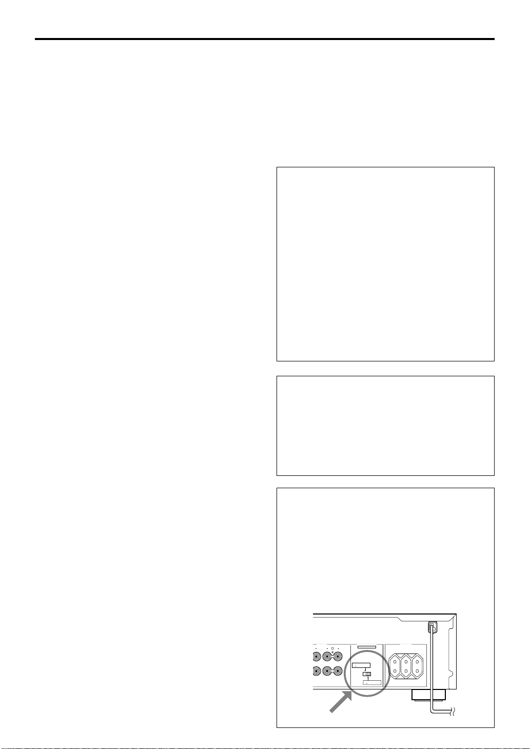
WARNING
Do not change the IMPEDANCE SELECTOR switch
setting while the power to this unit is on, otherwise
this unit may be damaged.
If this unit fails to turn on when the POWER switch is
pressed:
The IMPEDANCE SELECTOR switch may not be set to
either end. If so, set the switch to either end when this
unit’s power supply is completely cut off.
(Europe model)
SPEAKERS
EE INSTRUCTION MANUAL FOR CORRECT SETTING.
IMPEDANCE SELECTOR
SET BEFORE POWER ON
L
A OR B : 6ΩMIN. /SPEAKER
A B : I2
Ω
MIN. /SPEAKER
A OR B : 4ΩMIN. /SPEAKER
A B : 8
Ω
MIN. /SPEAKER
l00W MAX. TOTAL
AC OUTLETS
SWITCHED
MAINS
E-2
IMPEDANCE SELECTOR
NOTES ABOUT THE REMOTE CONTROL
English
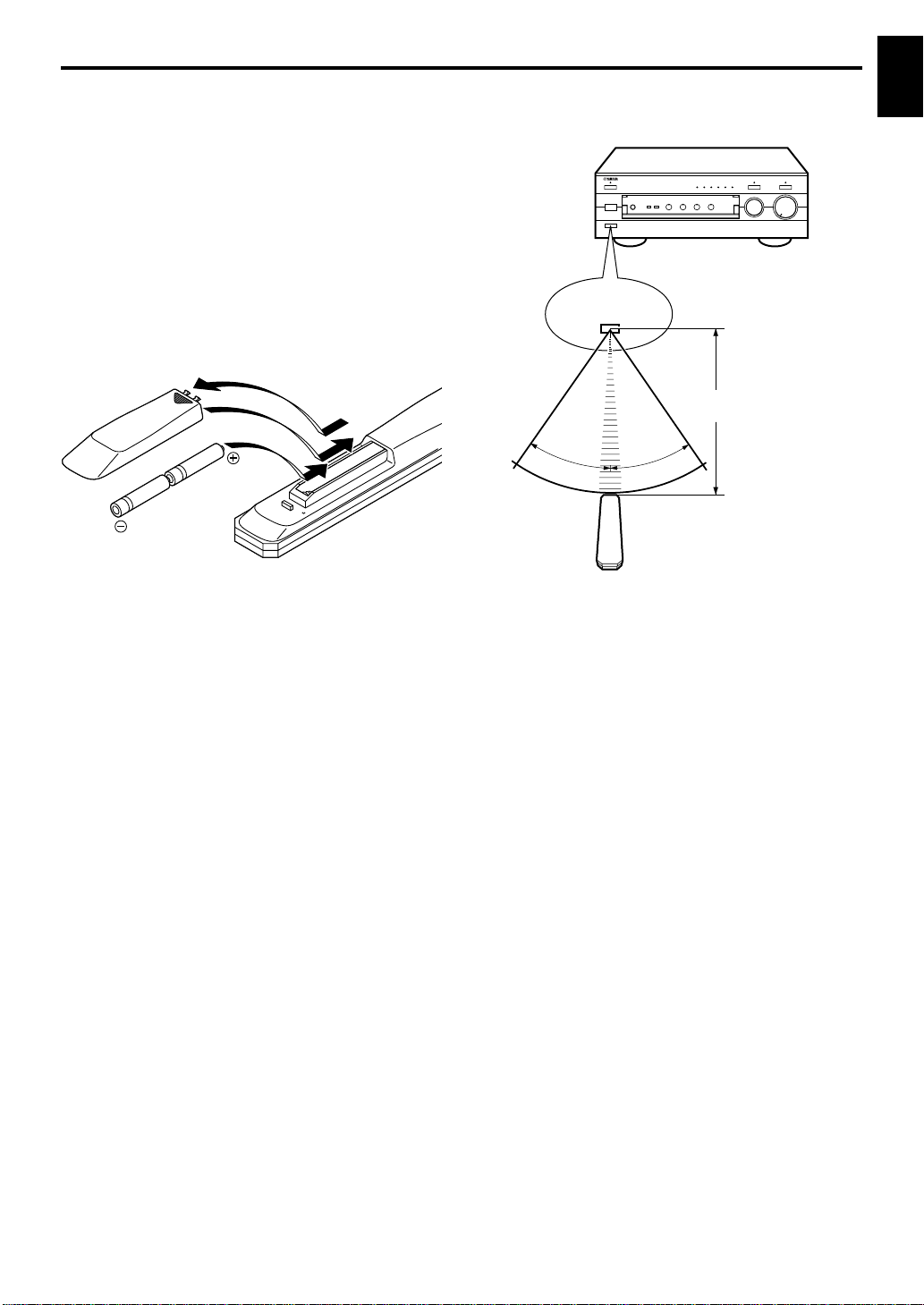
Battery installation
Since the remote control will be used for many of this unit’s
control operations, you should begin by installing the
supplied batteries.
1. Turn the remote control over and remove the battery
compartment cover by sliding it in the direction of the
arrow.
2. Insert the batteries (AA, R6, UM-3 type) according to the
polarity markings on the inside of the battery
compartment.
3. Close the battery compartment cover.
1
3
2
Battery replacement
If you notice that the remote control must be used closer to
the main unit, the batteries are weak. Replace both
batteries with new ones.
Notes
● Use AA, R6, UM-3 batteries.
● Be sure the polarities are correct. (See the illustration
inside the battery compartment.)
● Remove the batteries if the remote control is not used for
an extended period of time.
● If batteries leak, dispose of them immediately. Avoid
touching the leaked material and contact with clothing,
etc. Clean the battery compartment thoroughly before
installing new batteries.
Remote control operation range
REC OUT
CD
TAPE
TUNER
MD
PHONO
AUX
Remote control
sensor
Within approximately
6 m (19.7 feet)
30°
Notes
● The area between the remote control and the main unit
must be clear of large obstacles.
● Do not expose the remote control sensor to strong
lighting, in particular, an inverter type fluorescent lamp;
otherwise, the remote control may not work properly. If
necessary, position the main unit away from direct
lighting.
30°
E-3

CONNECTIONS
Caution: Plug in this unit and other components after all connections are completed.
● All connections must be correct, that is to say L (left) to L, R (right) to R, “+” to “+” and “–” to “–”. Also refer to the owner’s
manual for each of your components.
● Use RCA type pin plug cables for audio/video units except speakers.
● The output (or input) terminals of YAMAHA audio/video units numbered 1, 2, 3, 4, etc. on the rear panel must be
connected to the same-numbered terminals of this unit.
Turntable
GND
R
GND
R
OUTPUT
L
PHONO
1
CD/DVD
L
Tuner
OUTPUT
Tape deck, etc.
LINE IN
LINE OUT
Right Left
Speakers A
(Europe model)
L
R
TUNER
2
IN
3
(PLAY)
TAPE
OUT
4
(REC)
IN
3
(PLAY)
MD
OUT
4
(REC)
AUX
L
R
A
B
3
SPEAKERS
R
CAUTION
:SEE INSTRUCTION MANUAL FOR CORRECT SETTING.
L
IMPEDANCE SELECTOR
SET BEFORE POWER ON
A OR B : 6ΩMIN. /SPEAKER
Ω
MIN. /SPEAKER
A B : I2
A OR B : 4ΩMIN. /SPEAKER
Ω
MIN. /SPEAKER
A B : 8
*
l00W MAX. TOTAL
1
AC OUTLETS
SWITCHED
*
2
MAINS
*
OUTPUT
*
1
,
*
CD player or
DVD player
2
3
,
: Refer to page 5 for descriptions.
*
: Indicates the direction of signals.
Video cassette player,
etc.
E-4
AUDIO OUT
MD recorder, etc.
LINE OUT
LINE IN
Right
To AC outlet
Left
Speakers B
 Loading...