

Yamaha Audio AX-392 User Manual

AX-392
Natural Sound Stereo Integrated Amplifier
Préampli/ampli de puissance stéréo de la série “Natural Sound”
Natural Sound Stereo-Verstärker
Natural Sound Integrerad Stereo Förstärkare
Amplificatore integrato stereo a Suono Naturale
B G R T
Amplificador integrado estéreo de Sonido Natural
Natural Sound Geïntegreerde Stereo Versterker
OWNER’S MANUAL
MODE D’EMPLOI
BEDIENUNGSANLEITUNG
BRUKSANVISNING
MANUALE DI ISTRUZIONI
MANUAL DE INSTRUCCIONES
GEBRUIKSAANWIJZING
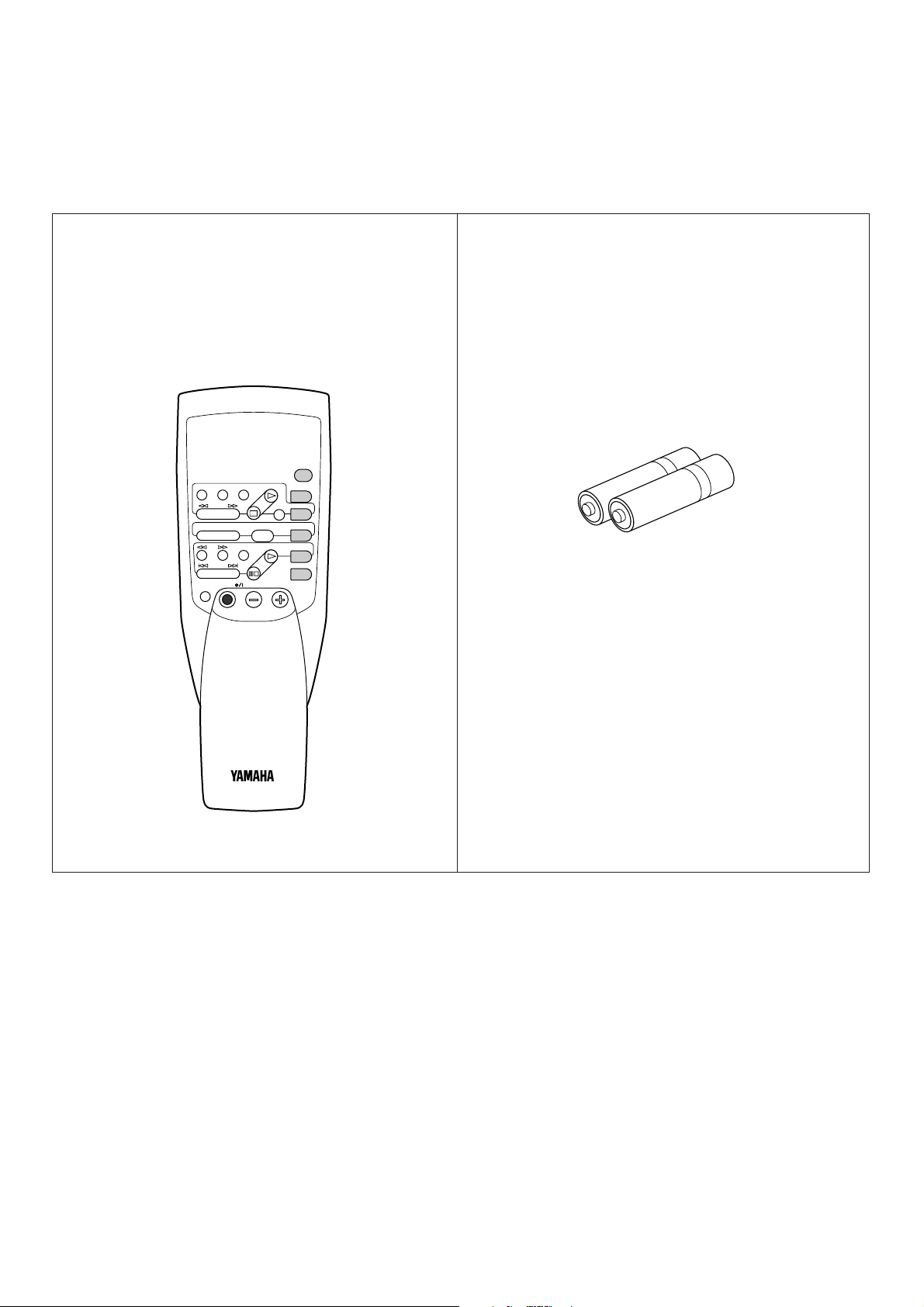
SUPPLIED ACCESSORIES
YAMAHA HiFi SYSTEM
REMOTE CONTROL TRANSMITTER
MD
REC/PAUSE
DIR BDIR A
PLAY
DISC
VOLUME
PLAY
AUX
PRESET
A/B/C/D/E
–+
SLEEP
TAPE
A/B
TUNER
CD
PHONO
POWER
ACCESSOIRES FOURNIS
MITGELIEFERTES ZUBEHÖR
MEDFÖLJANDE TILLBEHÖR
ACCESSORI IN DOTAZIONE
ACCESORIOS INCLUIDOS
BIJGELEVERDE ACCESSOIRES
●
After unpacking, check that the following parts are contained.
●
Après le déballage, vérifier que les pièces suivantes sont incluses.
●
Nach dem Auspacken überprüfen, ob die folgenden Teile vorhanden sind.
●
Kontrollera efter det apparaten packats upp att följande delar finns med.
●
Verificare che tutte le parti seguenti siano contenute nell’imballaggio dell’apparecchio.
●
Desembale el aparato y verificar que los siguientes accesorios están en la caja.
●
Controleer na het uitpakken of de volgende onderdelen voorhanden zijn.
●
Remote Control Transmitter
●
Emetteur de télécommande
●
Fernbedienung
●
Fjärrkontroll
●
Telecomando
●
Transmisor del control remoto
●
Afstandbediening
●
Batteries (size AA, R6, UM-3)
●
Piles (taille AA, R6, UM-3)
●
Batterien (Größe AA, R6, UM-3)
●
Batterier (storlek AA, R6, UM-3)
●
Batterie (dimensioni AA, R6, UM-3)
●
Pilas (tamaño AA, R6, UM-3)
●
Batterijen (maat AA, R6, UM-3)
2

Thank you for selecting this YAMAHA stereo amplifier.
FEATURES
● 60W + 60W (8Ω) RMS Output Power, 0.04% THD, 20–20,000 Hz
● High Dynamic Power, Low Impedance Drive Capability
● Continuously Variable LOUDNESS Control
● CD DIRECT AMP Switch to Reproduce the Purest CD Sound
● Remote Control Capability
CONTENTS
English
SUPPLIED ACCESSORIES ..............................................................................2
FEATURES.........................................................................................................3
CAUTION ...........................................................................................................4
NOTES ABOUT THE REMOTE CONTROL TRANSMITTER ............................5
CONNECTIONS ................................................................................................6
CONTROLS AND THEIR FUNCTIONS .............................................................8
OPERATIONS ..................................................................................................11
TROUBLESHOOTING .....................................................................................14
SPECIFICATIONS ...........................................................................................15
3
CAUTION: READ THIS BEFORE OPERATING YOUR UNIT.
MAINS
CAUTION
SEE INSTRUCTION MANUAL FOR CORRECT SETTING.
A OR B : 4ΩMIN. /SPEAKER
A B : 8
Ω
MIN. /SPEAKER
SPEAKERS
A
B
AC OUTLETS
SWITCHED
l00W MAX. TOTAL
A OR B : 8ΩMIN. /SPEAKER
A B : 12
Ω
MIN. /SPEAKER
IMPEDANCE SELECTOR
SET BEFORE POWER ON
1. To assure the finest performance, please read this manual
carefully. Keep it in a safe place for future reference.
2. Install this unit in a cool, dry, clean place – away from
windows, heat sources, sources of excessive vibration,
dust, moisture and cold. Avoid sources of humming
(transformers, motors). To prevent fire or electrical shock,
do not expose the unit to rain or water.
3. Never open the cabinet. If something drops into the set,
contact your dealer.
4. Do not use force on switches, controls or connection wires.
When moving the unit, first disconnect the power plug and
the wires connected to other equipment. Never pull the
wires themselves.
5. The openings on the cabinet assure proper ventilation of
the unit. If these openings are obstructed, the temperature
inside the cabinet will rise rapidly. Therefore, avoid placing
objects against these openings, and install the unit in wellventilated condition. Be sure to allow a space of at least 10
cm behind, 10 cm on the both sides and 20 cm above the
top panel of the unit. Otherwise it may not only damage the
unit, but also cause fire.
6. Always set the VOLUME control to “–
” before starting
∞
the audio source play: increase the volume gradually to an
appropriate level after the play has been started.
7. Do not attempt to clean the unit with chemical solvents;
this might damage the finish. Use a clean, dry cloth.
8. Be sure to read the “TROUBLESHOOTING” section
regarding common operating errors before concluding that
the unit is faulty.
9. When not planning to use this unit for long periods of
time (ie., vacation, etc.), disconnect the AC power plug
from the wall outlet.
This unit is not disconnected from the AC power source as
long as it is connected to the wall outlet, even if this unit
itself is turned off. This state is called the standby mode.
In this state, this unit is designed to consume a very small
quantity of power.
For U.K. customers
If the socket outlets in the home are not suitable for the plug
supplied with this appliance, it should be cut off and an
appropriate 3 pin plug fitted. For details, refer to the
instructions described below.
Note: The plug severed from the mains lead must be
destroyed, as a plug with bared flexible cord is hazardous if
engaged in a live socket outlet.
SPECIAL INSTRUCTIONS FOR U.K. MODEL
IMPORTANT:
THE WIRES IN MAINS LEAD ARE COLOURED IN
ACCORDANCE WITH THE FOLLOWING CODE:
Blue: NEUTRAL
Brown: LIVE
As the colours of the wires in the mains lead of this
apparatus may not correspond with the coloured markings
identifying the terminals in your plug, proceed as follows:
The wire which is coloured BLUE must be connected to the
terminal which is marked with the letter N or coloured
BLACK. The wire which is coloured BROWN must be
connected to the terminal which is marked with the letter L
or coloured RED. Making sure that neither core is
connected to the earth terminal of the three pin plug.
10.To prevent lightning damage, disconnect the AC power
plug and antenna cable when there is an electrical storm.
11.Grounding or polarization – Precautions should be taken
so that the grounding or polarization of an appliance is not
defeated.
12.Do not connect audio equipment to the AC outlet on the
rear panel if the equipment requires more power than the
outlet is rated to provide.
13.Voltage Selector (China and General Models only)
The voltage selector on the rear panel of this unit must
be set for your local main voltage BEFORE plugging
into the AC main supply.
Voltages are 110/120/220/240 V AC, 50/60 Hz.
IMPORTANT
Please record the serial number of this unit in the space
below.
Model:
Serial No.:
The serial number is located on the rear of the unit.
Retain this Owner’s Manual in a safe place for future
reference.
WARNING
TO REDUCE THE RISK OF FIRE OR ELECTRIC SHOCK,
DO NOT EXPOSE THIS UNIT TO RAIN OR MOISTURE.
4
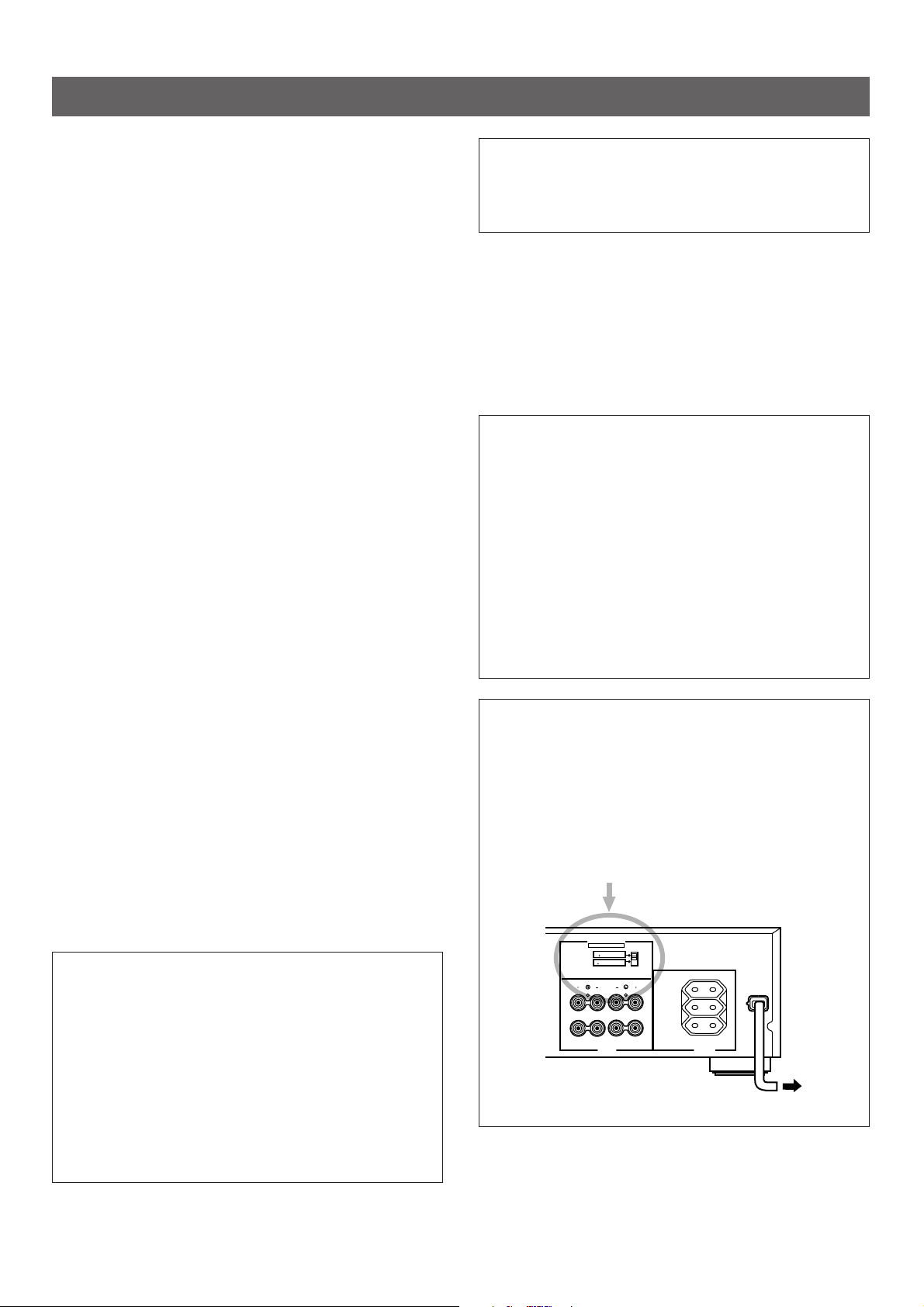
WARNING
Do not change the IMPEDANCE SELECTOR switch
setting while the power to this unit is on, otherwise this
unit may be damaged.
IF THIS UNIT FAILS TO TURN ON WHEN THE
STANDBY/ON SWITCH IS PRESSED;
The IMPEDANCE SELECTOR switch may not be set to
either end closely. If so, set the switch to either end closely.
IMPEDANCE SELECTOR
(Europe model)
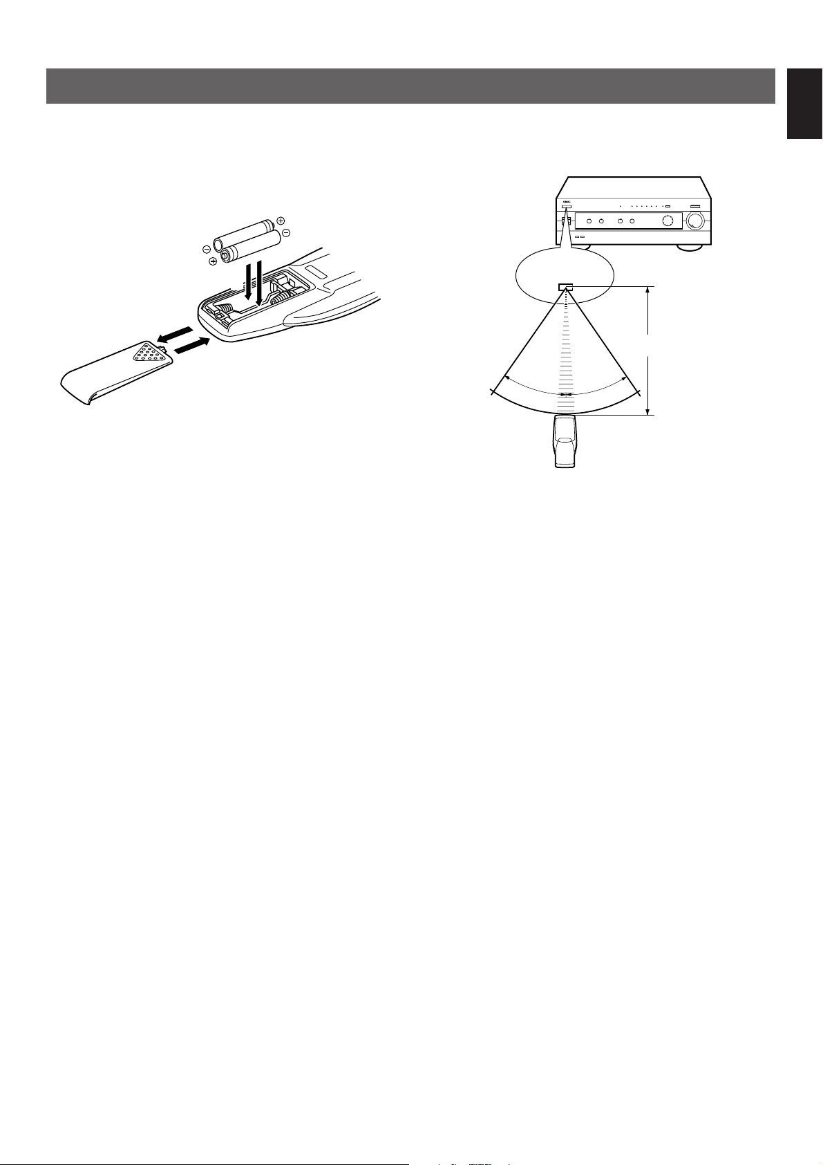
NOTES ABOUT THE REMOTE CONTROL TRANSMITTER
1
3
2
30°
30°
English
Battery installation
Battery replacement
If you find that the remote control transmitter must be used
closer to the main unit, the batteries are weak. Replace both
batteries with new ones.
Notes
●
Use only AA, R6, UM-3 batteries for replacement.
●
Be sure the polarities are correct. (See the illustration inside
the battery compartment.)
●
Remove the batteries if the remote control transmitter will
not be used for an extended period of time.
●
If batteries leak, dispose of them immediately. Avoid
touching the leaked material or letting it come in contact with
clothing, etc. Clean the battery compartment thoroughly
before installing new batteries.
Remote control transmitter operation range
Remote control
sensor
Within approximately
6 m (19.7 feet)
Notes
●
There should be no large obstacles between the remote
control transmitter and the main unit.
●
If the remote control sensor is directly illuminated by strong
lighting (especially an inverter type of fluorescent lamp etc.),
it might cause the remote control transmitter not to work
correctly. In this case, reposition the main unit to avoid
direct lighting.
5

CONNECTIONS
MDPHONOCDTUNER AUX TAPE
PLAY REC PLAY REC
21 3 43 4
GND
MAINS
CAUTION
SEE INSTRUCTION MANUAL FOR CORRECT SETTING.
A OR B : 4ΩMIN. /SPEAKER
A B : 8
Ω
MIN. /SPEAKER
SPEAKERS
A
B
AC OUTLETS
SWITCHED
l00W MAX. TOTAL
A OR B : 8ΩMIN. /SPEAKER
A B : 12
Ω
MIN. /SPEAKER
IMPEDANCE SELECTOR
SET BEFORE POWER ON
OUTPUT
LINE OUT
LINE IN
LINE OUT
LINE IN
AUDIO OUT
OUTPUT
GND
OUTPUT
Never plug in this unit and other components until all connections are completed.
●
When making connections between this unit and other components, be sure all connections are made correctly, that is to say L
(left) to L, R (right) to R, “+” to “+” and “–” to “–”. Also, refer to the owner’s manual for each component to be connected to this
unit.
●
If you have YAMAHA components numbered as 1, 2, 3, 4, etc. on the rear panel, connections can be made easily by only
connecting the output (or input) terminals of each component to the same-numbered terminals of this unit.
Speakers A
Turntable
Tape deck, etc.MD recorder, etc.
Right
Left
2
*
1
*
(Europe model)
To AC outlet
CD player
1
2
,
*
6
: Refer to “ABOUT THE ACCESSORY
*
TERMINALS” on page 7.
Tuner
Video cassette player,
LD player, etc.
Right
Left
Speakers B
 Loading...