

Yamaha Audio AX-390 User Manual

AX-390
Natural Sound Stereo Integrated Amplifier
Préampli/ampli de puissance stéréo de la série “Natural Sound”
Natural Sound Stereo-Verstärker
Natural Sound Integrerad Stereo Förstärkare
Amplificatore integrato stereo a Suono Naturale
Amplificador integrado estéreo de Sonido Natural
Natural Sound Geïntegreerde Stereo Versterker
OWNER’S MANUAL
MODE D’EMPLOI
BEDIENUNGSANLEITUNG
BRUKSANVISNING
MANUALE DI ISTRUZIONI
MANUAL DE INSTRUCCIONES
GEBRUIKSAANWIJZING
SUPPLIED ACCESSORIES
ACCESSOIRES FOURNIS
MITGELIEFERTE ZUBEHÖRTEILE
MEDFÖLJANDE TILLBEHÖR
ACCESSORI IN DOTAZIONE
ACCESORIOS INCLUIDOS
BIJGELEVERDE ACCESSOIRES
●
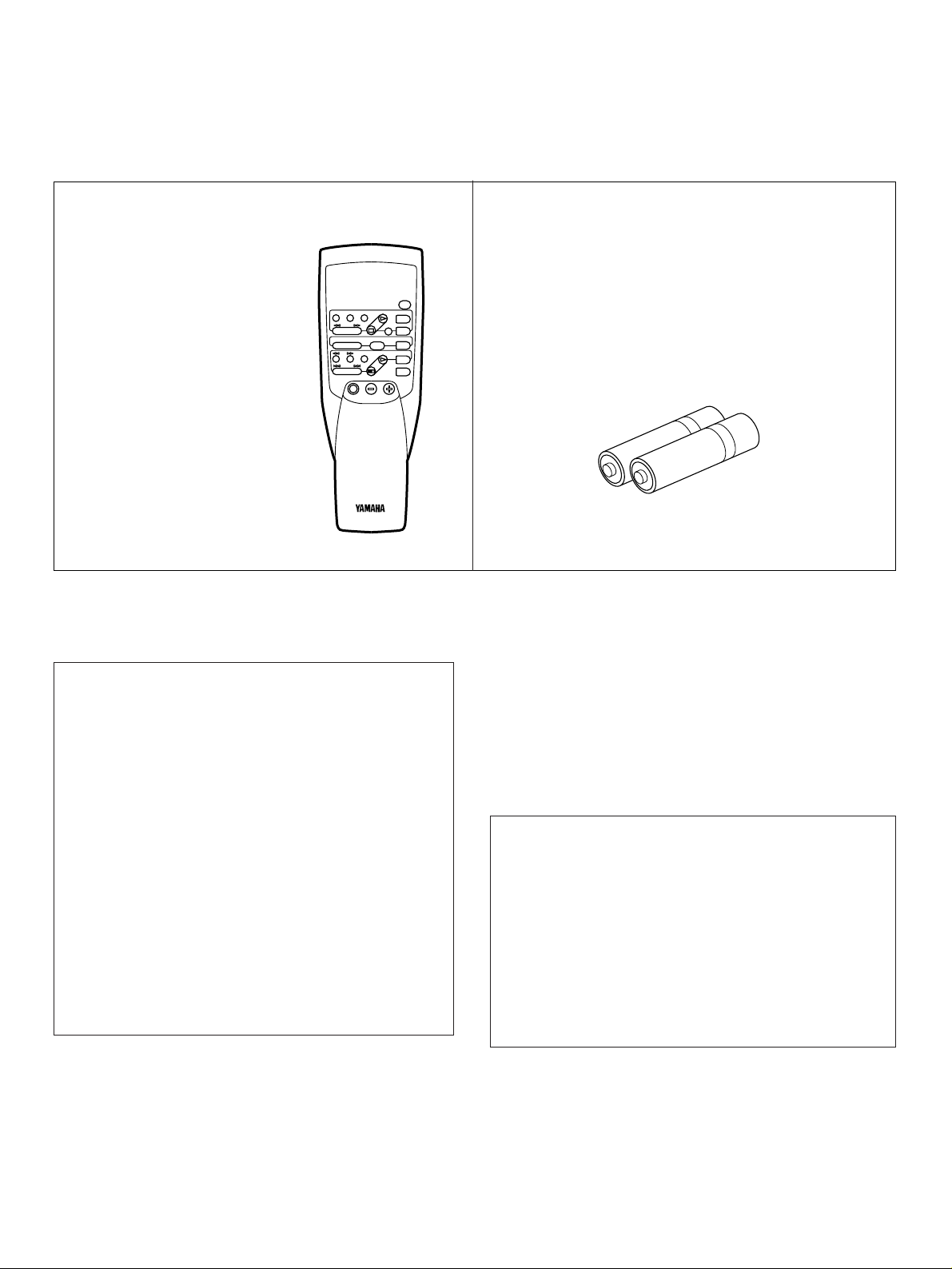
After unpacking, check that the following parts are included.
●
Après le déballage, vérifier que les pièces suivantes sont incluses.
●
Nach dem Auspacken überprüfen, ob die folgenden Teile vorhanden sind.
●
Kontrollera efter det apparaten packats upp att följande delar finns med.
●
Verificare che tutte le parti seguenti siano contenute nell’imballaggio dell’apparecchio.
●
Desembale el aparato y verificar que los siguientes accesorios están en la caja.
●
Controleer na het uitpakken of de volgende onderdelen voorhanden zijn.
●
Remote Control Transmitter
●
Emetteur de télécommande
●
Fernbedienungsgeber
●
Fjärrkontrollsändare
●
Telecomando
●
Transmisor del control remoto
●
Afstandbediening
●
Batteries (size AA, R6, UM-3)
●
Piles (taille AA, R6, UM-3)
●
Batterien (Größe AA, R6, UM-3)
●
Batterier (storlek AA, R6, UM-3)
●
Batterie (dimensioni AA, R6, UM-3)
●
Pilas (tamaño AA, R6, UM-3)
●
Batterijen (maat AA, R6, UM-3)
This product complies with the radio frequency
interference requirements of the Council Directive
82/499/EEC and/or 87/308/EEC.
Cet appareil est conforme aux prescriptions de la directive
communautaire 87/308/CEE.
Diese Geräte entsprechen der EG-Richtlinie 82/499/EWG
und/oder 87/308/EWG.
Dette apparat overholder det gaeldende EF-direktiv
vedrørende radiostøj.
Questo apparecchio è conforme al D.M.13 aprile 1989
(Direttiva CEE/87/308) sulla soppressione dei
radiodisturbi.
Este producto está de acuerdo con los requisitos sobre
interferencias de radio frequencia fijados por el Consejo
Directivo 87/308 CEE.
Dit product voldoet aan de EEG normen betreffende
radio-frekwentie storingen 82/499/EEG en/of
87/308/EEG.
For U.K. customers
If the socket outlets in the home are not suitable for the plug
supplied with this appliance, it should be cut off and an
appropriate 3 pin plug fitted. For details, refer to the
instructions described below.
Note: The plug severed from the mains lead must be
destroyed, as a plug with bared flexible cord is hazardous if
engaged in a live socket outlet.
Special Instructions for U.K. Model
IMPORTANT
THE WIRES IN THE MAINS LEAD ARE COLOURED IN
ACCORDANCE WITH THE FOLLOWING CODE:
Blue: NEUTRAL
Brown: LIVE
As the colours of the wires in the mains lead of this apparatus may
not correspond with the coloured markings identifying the terminals
in your plug, proceed as follows:
The wire which is coloured BLUE must be connected to the
terminal which is marked with the letter N or coloured BLACK. The
wire which is coloured BROWN must be connected to the terminal
which is marked with the letter L or coloured RED. Make sure that
neither core is connected to the earth terminal of the three pin plug.
2

Thank you for selecting this YAMAHA stereo amplifier.
FEATURES CONTENTS
English
●
60W + 60W (8Ω) RMS Output Power, 0.04% THD,
20–20,000 Hz
●
High Dynamic Power, Low Impedance Drive
Capability
●
Continuously Variable Loudness Control
●
CD DIRECT AMP Switch to Reproduce the Purest
CD Sound
●
Remote Control Capability
Supplied Accessories .....................................................2
Caution ...........................................................................3
Controls and Their Functions .........................................4
Connections ...................................................................6
Basic Operations ............................................................8
Notes about the Remote Control Transmitter................11
Troubleshooting ............................................................12
Specifications ...............................................................13
CAUTION: READ THIS BEFORE OPERATING YOUR UNIT.
1. To assure the finest performance, please read this manual
carefully. Keep it in a safe place for future reference.
2. Install this unit in a cool, dry, clean place – away from
windows, heat sources, sources of excessive vibration,
dust, moisture and cold. Avoid sources of humming
(transformers, motors). To prevent fire or electrical shock,
do not expose the unit to rain or water.
3. Never open the cabinet. If something drops into the set,
contact your dealer.
12.AC outlet
Do not connect audio equipment to the AC outlet on the
rear panel if that equipment requires more power than the
outlet is rated to provide.
13.Voltage Selector (General Model only)
The voltage selector on the rear panel of this unit
must be set for your local main voltage BEFORE
plugging into the AC main supply.
Voltages are 110/120/220/240V AC, 50/60 Hz.
4. Do not use force on switches, controls or connection
wires. When moving the unit, first disconnect the power
plug and the wires connected to other equipment. Never
pull the wires themselves.
5. The openings on the cabinet assure proper ventilation of
the unit. If these openings are obstructed, the temperature
inside the cabinet will rise rapidly. Therefore, avoid
placing objects against these openings, and install the unit
in well-ventilated condition. Make sure to allow a space of
at least 10 cm behind, on the both sides and above the top
panel of the unit. Otherwise it may not only damage the
unit, but also cause fire.
6. Always set the VOLUME control to “–
the audio source play. Increase the volume gradually to an
appropriate level after playback has been started.
” before starting
∞
7. Do not attempt to clean the unit with chemical solvents;
this might damage the finish. Use a clean, dry cloth.
8. Be sure to read the “TROUBLESHOOTING” section
regarding common operating errors before concluding that
the unit is faulty.
9. When not planning to use this unit for long periods of time
(ie., vacation, etc.), disconnect the AC power plug from the
wall outlet.
IMPORTANT
Please record the serial number of this unit in the space
below.
Serial No.:
The serial number is located on the rear of the unit.
Retain this Owner’s Manual in a safe place for future
reference.
WARNING
TO REDUCE THE RISK OF FIRE OR ELECTRIC SHOCK,
DO NOT EXPOSE THIS UNIT TO RAIN OR MOISTURE.
The apparatus is not disconnected from the AC power
source as long as it is connected to the wall outlet, even if
the apparatus itself is turned off.
10.To prevent lightning damage, disconnect the AC power
plug and disconnect the antenna cable when there is an
electrical storm.
11.Grounding or polarization – Precautions should be taken
so that the grounding or polarization of an appliance is not
defeated.
3
SPEAKERS
A
B
ON
OFF
ON
OFF
PHONES
POWER
TAPE 1
MONITOR
AUX
TUNER
CD
PHONO
TAPE 2
CD DIRECT
AMP
VOLUME
NATURAL SOUND STEREO AMPLIFIER AX-390
COPY
BALANCE
BASS
TREBLE
LOUDNESS
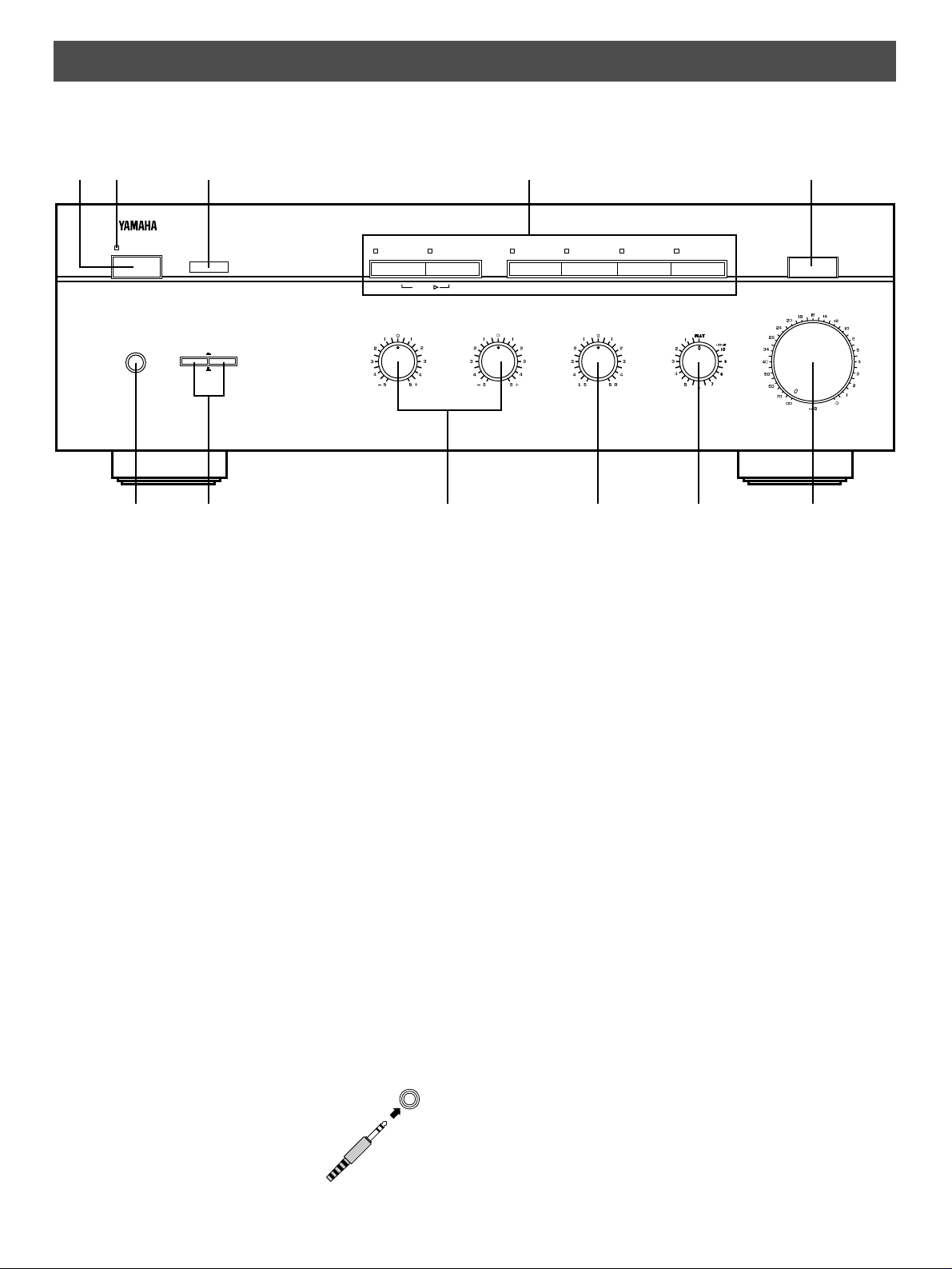
CONTROLS AND THEIR FUNCTIONS
PHONES
FRONT PANEL
12 3 4 5
67 8 9 0 A
1 POWER switch
Press this switch to switch the power on. Press it again to
switch the power off.
* Standby mode
<Europe and U.K. models only>
While the power is on, pressing the POWER key on the
remote control transmitter switches the unit to the standby
mode. (In this mode, the power indicator is half illuminated.)
2 Power indicator
Lights up while the power is on.
3 Remote control sensor
Receives signals from the remote control transmitter.
4 Input selector buttons and indicators
Select a program source to listen to. The indicator above the
selected button (source) will light up.
5 CD DIRECT AMP switch
Press this switch inward to listen to a CD source in the purest
sound. (Refer to page 10 for details.)
6 PHONES jack
When you listen with headphones, connect the headphones to
the PHONES jack. When listening with
headphones privately, set both the
SPEAKERS A and B switches to the
OFF position.
7 SPEAKERS switches
Set the switch A or B (or both A and B) for the speaker system
(connected to this unit) you will use to the ON position. Set the
switch for the speaker system you will not use to the OFF
position.
8 Tone controls
BASS
Used to increase or decrease the low frequency response.
The 0 position produces flat response.
TREBLE
Used to increase or decrease the high frequency response.
The 0 position produces flat response.
9 BALANCE control
Adjusts the balance of the output volume to the left and right
speakers to compensate for sound imbalance caused by
speaker location or listening room conditions.
0 Continuously variable LOUDNESS control
Used to compensate for the human ears’ loss of sensitivity to
high and low-frequency ranges at low volume.
A VOLUME control
Used to raise or lower the volume level.
4
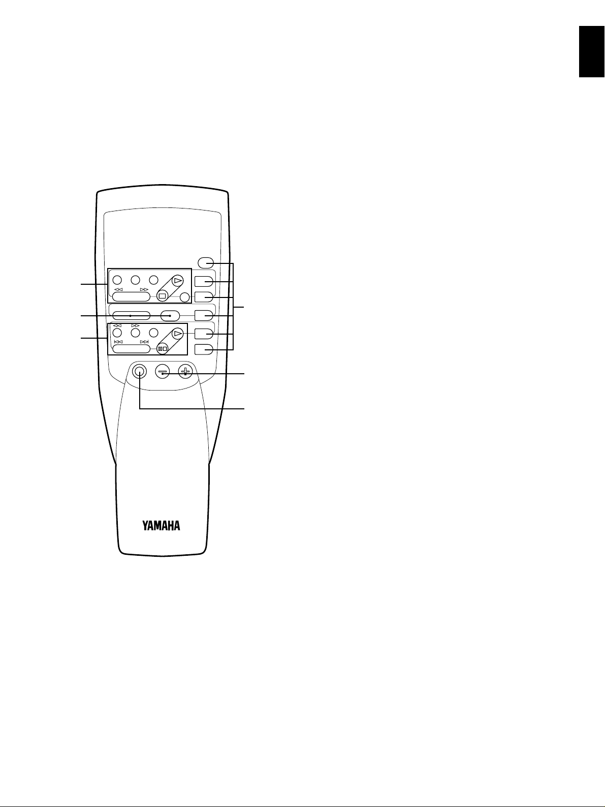
REMOTE CONTROL TRANSMITTER
YAMAHA HIFI SYSTEM
REMOTE CONTROL TRANSMITTER
TAPE 2
REC/PAUSE
DIR BDIR A
PLAY
DISC
POWER VOLUME
PLAY
AUX
PRESET
A/B/C/D/E
–+
TAPE 1
A/B
TUNER
CD
PHONO
1
3
1
2
2
3
The remote control transmitter provided with this unit is designed to control all the most commonly used functions of the unit. If the
CD player, tuner and tape deck connected to this unit are YAMAHA components designed for remote control compatibility, then this
remote control transmitter will also control various functions of each component.
For Control of This Unit
1
Input selector keys
Selects input source.
2 VOLUME +/– keys
Turns the volume level up/down.
3 POWER key
Turns the power on/off.
* <Europe and U.K. models only>
While the power is on, pressing the POWER key on the
remote control transmitter switches the unit from the
power-on mode to the standby mode, and vice versa. (In
the standby mode, the power indicator on the front panel is
half illuminated.)
English
For Other Component Control
Identify the remote control transmitter keys with your
component’s keys. If these keys are identical, their functions
will be the same. On each key function, refer to the
corresponding instruction on your component’s manual.
1 Tape deck keys
Controls tape deck.
DIR A, B and A/B are applicable only to double
*
cassette tape deck.
For a single cassette deck with automatic reverse
*
function, pressing DIR A will reverse the direction of
tape running.
2 Tuner keys
Controls tuner.
+: Selects higher preset station number.
–: Selects lower preset station number.
A/B/C/D/E Selects the group (A – E) of preset station
numbers.
3 CD player keys
Controls compact disc player.
DISC is applicable only to compact disc changer.
*
5
 Loading...