

Yamaha Audio AW4416 User Manual

Version 2.0 Manual Supplement
E

AW4416 Version 2.0 Manual Supplement
This manual supplement explains the functions and specifications
that have been added or changed in version 2.0 of the AW4416’s system software. “Operation” explains how to use the new functionality,
and “Reference” provides detailed explanations of all items in the
pages that were added. Since revisions have also occurred in the
MIDI data format in the appendices, this material is also provided.
Operation
Extensions to the Quick Rec function ............ 3
Quickly assign input sources to tracks.......... 3
Shortcut key definitions................................. 5
Added/modified MIDI functions.................... 6
Changes in the MIDI Setup page/
MIDI Sync page ......................................... 6
Using control changes to operate
AW4416 parameters .................................. 9
Using parameter changes to perform
AW4416 operations................................. 11
Transmitting internal AW4416 settings
via MIDI (Bulk Dump).............................. 11
Newly added MIDI Remote function.......... 13
Additional functionality for Automix .......... 19
Mini YGDAI plug-in system compatible
I/O card operations................................... 21
Backing up an I/O card .............................. 21
Restoring to an I/O card ............................. 22
Contents
Reference
QUICK REC screen ............................ 23
Quick Rec 2 page .........................................23
UTILITY screen.................................. 25
CTRL Key Asgn. page....................................25
MIDI screen ...................................... 27
CTL Asgn. page.............................................27
Bulk Dump page...........................................31
Remote A 1-8/Remote A 9-16/
Remote B 1-8/Remote B 9-16 pages...........33
MIDI data format .........................................37
2
Version 2.0 Manual Supplement
Operation
Extensions to the Quick Rec function
The Quick Rec screen now has two pages: Quick Rec
1 and Quick Rec 2. Operations corresponding to what
was the previous Quick Rec page are performed in
the Quick Rec 1 page, and the newly added Quick
Rec 2 page allows the various input signals/input
channels to be freely patched to the tracks of the
recorder.
By using the appropriate page (Quick Rec 1 or Quick
Rec 2), you can make patching settings more efficiently.
Quickly assign input sources to tracks
By using the Quick Rec 2 page, you can quickly
assign any input source/input channel to a recorder
track. Here’s how.
In the WORK NAVIGATE section, press the
1
[Quick Rec] key
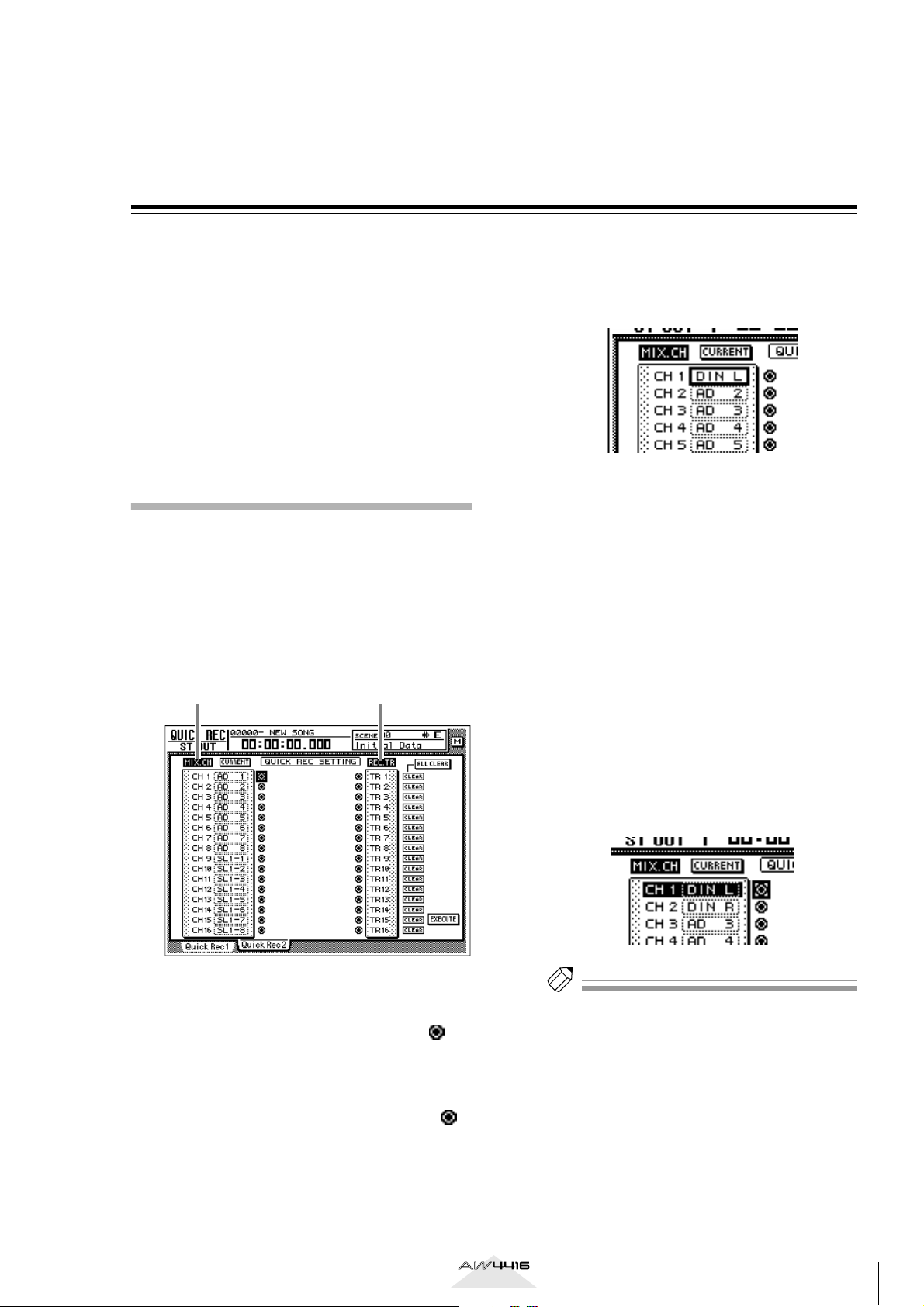
The Quick Rec 2 page will appear. This page displays the following information.
1 2
→
[F2] (Quick Rec 2) key.
To change the input source that is assigned
2
to an input channel, move the cursor to
the number box of the corresponding
channel, and turn the [DATA/JOG] dial.
The following types of input source can be
assigned to an input channel.
• AD 1–AD 8 .............Input signals from INPUT
1–8 jacks
• SL1-1–SL1-8 ............Inputs 1–8 from an I/O
card (slot 1)
• SL2-1–SL2-8 ............Inputs 1–8 from an I/O
card (slot 2)
• DIN L/DIN R ..........L or R channels from the
DIGITAL STEREO IN jack
• SMP 1–SMP 8 ..........Sampling pads 1–8
• MET ........................Internal metronome
A
MIX.CH (Input channel)
This area shows the type of input signal that is
assigned to each input channel 1–16. The
symbols (jacks) displayed at the right of this area
indicate the direct output of each input channel.
B
REC.TR (Recorder track)
This area shows tracks 1–16 (Tr1–Tr16). The
symbols (jacks) displayed at the left of this area
indicate the input to each track.
In the MIX.CH area, move the cursor to the
3
patch-source jack, and press the [ENTER]
key.
The corresponding input channel will be highlighted, and selected as the patch-source.
Tip!
If you move the cursor to a highlighted input channel
and press the [ENTER] key once again, the selection
will be cancelled.
Version 2.0 Manual Supplement
3
AW4416 Version 2.0 Manual Supplement
In the REC.TR area, move the cursor to the
4
jack for the desired patch-destination track,
and press the [ENTER] key.
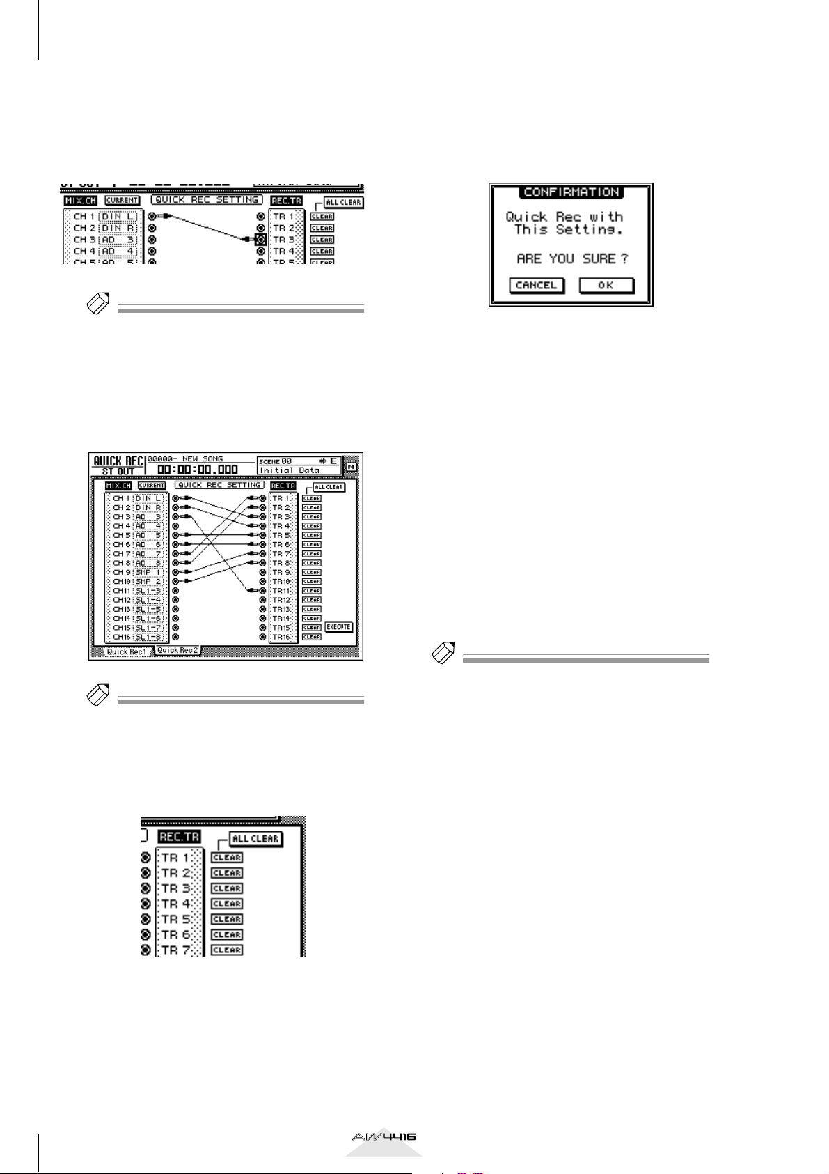
The patch-source and patch-destination in the
screen will be connected by a patch cable.
Tip!
• You may perform steps 3 and 4 in reverse order.
• It is also possible to connect the direct output of the
same channel to multiple tracks. However, it is not
possible to connect multiple direct outputs to a single track.
Make connections for other input channels
5
in the same way.
When you are finished making patch cable
6
connections, move the cursor to the EXECUTE button located in the lower right of
the display, and press the [ENTER] key.
The following popup window will appear.
To execute the Quick Rec function, move
7
the cursor to the OK button and press the
[ENTER] key.
To cancel the operation, move the cursor to the
CANCEL button and press the [ENTER] key.
When you execute Quick Rec, the internal settings of the AW4416 will change as follows.
• The input patch and recorder input settings will
be set according to the settings of the Quick
Rec 2 page.
• Assignments to the stereo bus will be forcibly
cancelled for any input channel to which a
patch cable is connected.
• Channel library number 01 will be recalled for
the monitor channel of any track to which a
patch cable is connected, restoring it to the
default condition.
Tip!
• To cancel a specific patch cable, move the cursor to
the CLEAR button located at the right of the corresponding recorder input, and press the [ENTER] key.
• To cancel all patch cables, move the cursor to the
ALL CLEAR button located at the upper right of the
display, and press the [ENTER] key.
Tip!
If desired, each input channel to which a patch cable
is connected can be initialized when you execute
Quick Rec. To do this, move the cursor to the FLAT/
CURRENT button located in the upper left of the display, and press the [ENTER] key to make the button
read “FLAT.”
[Reference pages]
Details on the Quick Rec 2 page
→
P.23
4
Version 2.0 Manual Supplement
Shortcut key definitions
The new version of the system program lets you assign
desired functions to various combinations of the
[SHIFT] key located at the right of the display (the
[CTRL] key), in order to create your own shortcut
keys.
In the UNIT section, press the [UTILITY] key
1
→
[F5] (CTRL Key Assign) key.
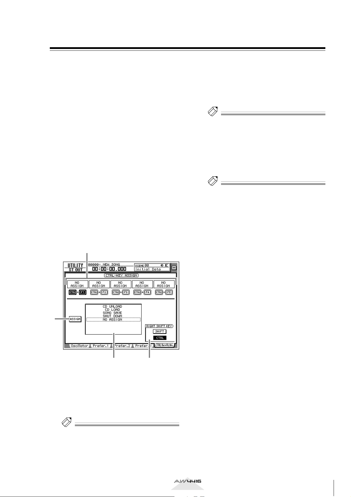
The CTRL Key Asgn. page added in version 2.0
will appear.
In the RIGHT SHIFT KEY area, move the
2
cursor to the CTRL button, and press the
[ENTER] key.
The buttons in the RIGHT SHIFT KEY area are
used to switch the function of the [SHIFT] key
located at the right of the display. When you turn
on the CTRL button, the [SHIFT] key located at
the right of the display will function as a [CTRL]
key to access shortcuts. (Even in this case, the
function of the [SHIFT] key located at the left of
the display will not be affected.)
If you turn the CTRL button on, you will be able
to assign specific functions (e.g., access a page or
turn a certain function on/off) to combinations of
the [CTRL] + [F1] – [CTRL] + [F5] keys.
1
Select the shortcut key combination
3
(CTRL+F1–CTRL+F5) to which you want to
assign a function, move the cursor to that
combination, and press the [ENTER] key.
The corresponding symbol will be highlighted,
allowing you to assign a function.
Tip!
When the AW4416 is in its initial state, all shortcut
keys are set to No Assign.
Move the cursor to the function list, and
4
use the [DATA/JOG] dial to select the function that you want to assign.
For a list of the functions that can be selected,
refer to page 25.
Tip!
If you select SCENE RECALL as the assigned function,
a field allowing you to specify the scene number will
appear at the right of the function list. Move the cursor to this area, and use the [DATA/JOG] dial to specify the scene number.
Move the cursor to the ASSIGN button,
5
and press the [ENTER] key.
A popup window will appear, asking you to confirm the assignment.
3
2
A
CTRL+F1 –CTRL+F5
Function list
B
C
Assign button
D
RIGHT SHIFT KEY area
Tip!
To return the [SHIFT] key located at the right of the
display to its normal function, move the cursor to the
SHIFT button and press the [ENTER] key.
4
To confirm the assignment, move the cur-
6
sor to the OK button and press the [ENTER]
key.
To execute the assigned function, hold
7
down the [CTRL] key (the [SHIFT] key at
the right of the display), and press the corresponding function key.
[Reference pages]
For details on the CTRL Key Asgn. page
→
P.25
Version 2.0 Manual Supplement
5
AW4416 Version 2.0 Manual Supplement
Added/modified MIDI functions
MIDI-related functionality has been significantly
enhanced in version 2.0. The following functions and
specifications have been added or modified.
●
The various items in the previous MIDI Setup page
and MIDI Sync page have been reorganized into
the MIDI Setup 1 page and MIDI Setup 2 page.
●
You can now use control changes or parameter
changes to operate the parameters of the AW4416
from an external MIDI device.
●
Internal AW4416 settings can now be output via
MIDI.
●
A “MIDI Remote” function has been added, allowing you to use faders 1–16 and [ON] keys 1–16 to
control external MIDI devices.
●
As an MTC output destination, you can now select
MIDI/TO HOST/OPTION (option slot 2) in addition
to the previous choice of the MTC OUT connector.
●
MTC is now transmitted from the MTC OUT connector at all times.
●
As the port used to transmit/receive MIDI messages, you can now select OPTION (option slot 2)
in addition to the previous choices of MIDI/TO
HOST. This setting will be valid when a I/O card
able to transmit/receive MIDI messages (such as the
mLAN card “MY8-mLAN” expected to go on sale
soon) is installed in option slot 2.
The additions and changes for each item are
explained below.
Changes in the MIDI Setup page/ MIDI Sync page
The various items in the previous MIDI Setup page
and MIDI Sync page have been reorganized into the
MIDI Setup 1 page and MIDI Setup 2 page. The content of the new pages is as follows.
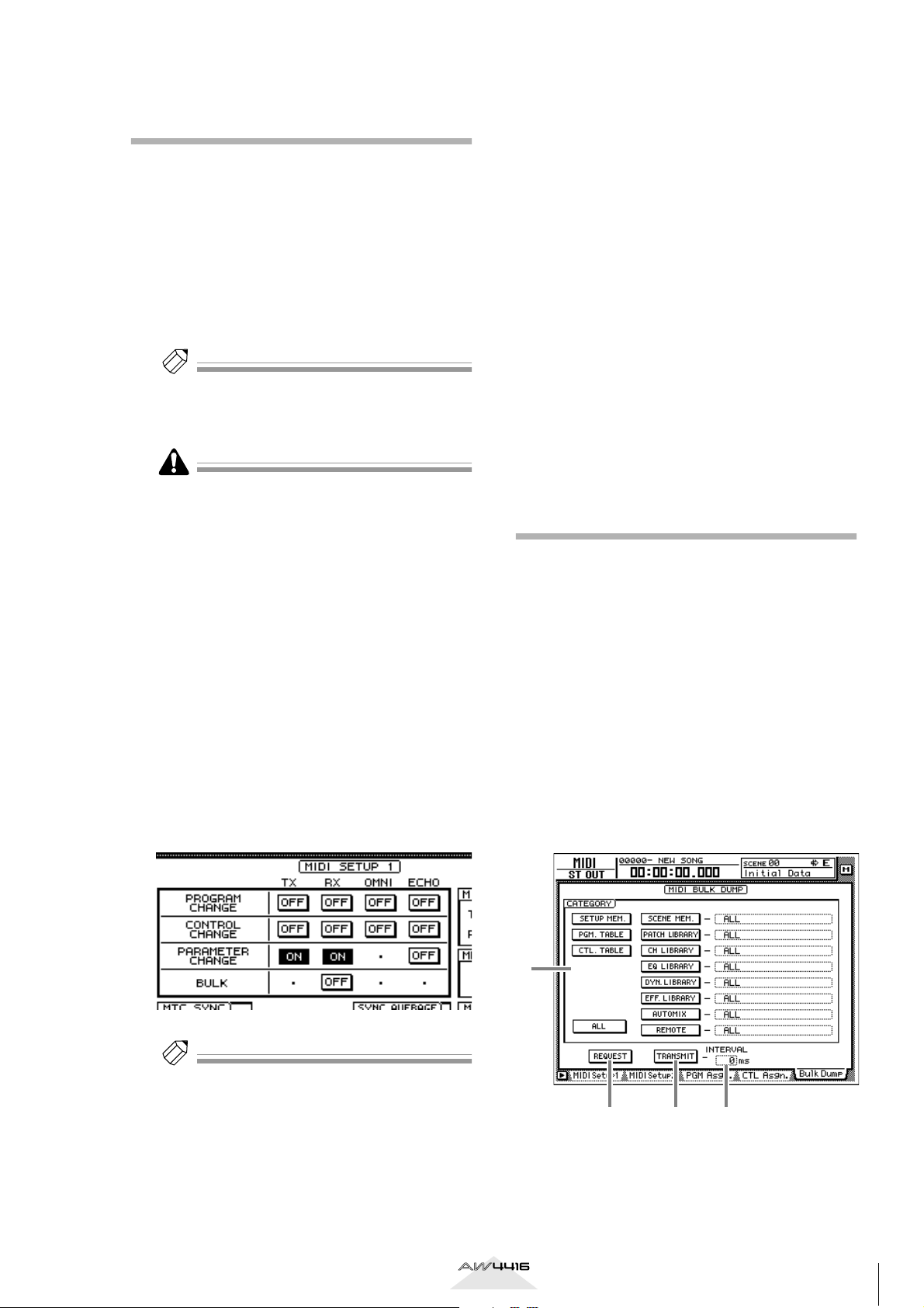
■
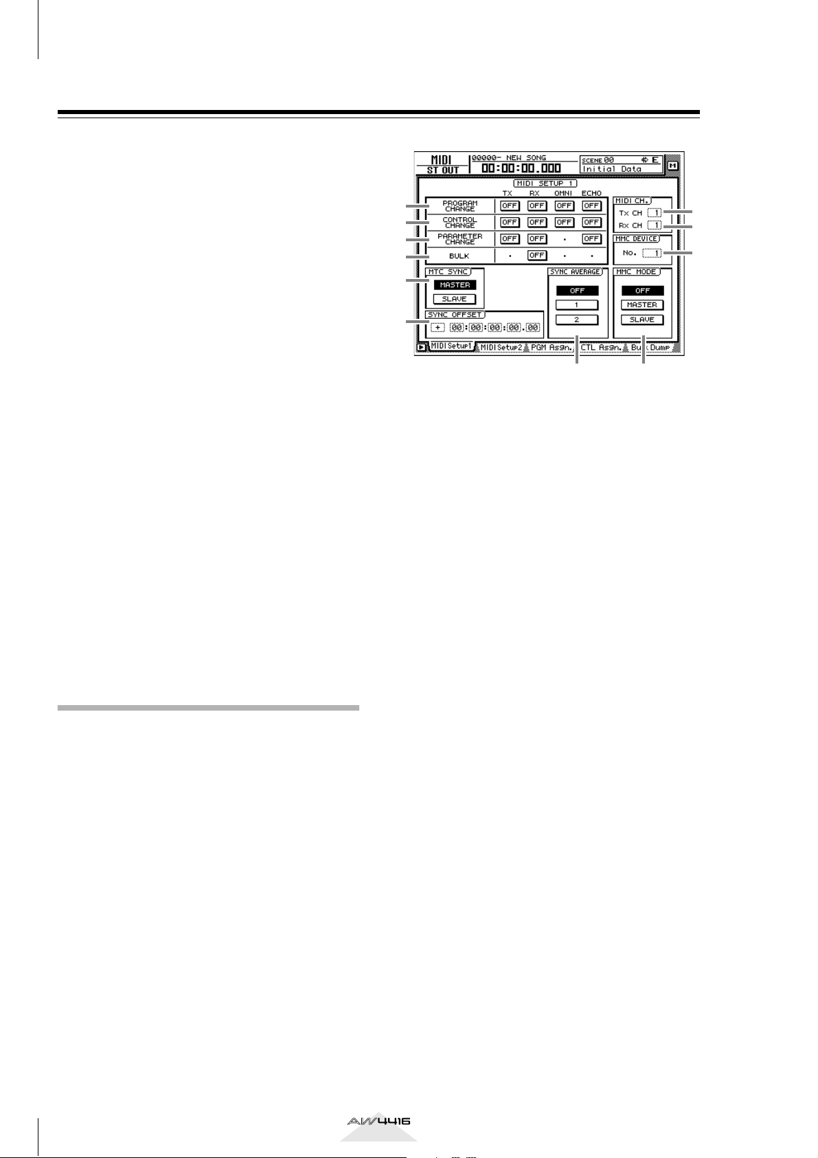
MIDI Setup 1 page
Here you can select the MIDI transmit/receive channels, turn transmission and reception of various MIDI
messages on/off, and make settings related to MIDI
synchronization.
1
2
3
4
5
6
A PROGRAM CHANGE
Here you can make settings for program change
message transmission/reception. Each button has
the following function.
● TX
If this button is on, the program change number
assigned to a scene will be transmitted when that
scene is recalled.
● RX
If this button is on, a scene will be recalled when
the program change number assigned to that
scene is received.
● OMNI
If this button is on, program changes of all MIDI
channels will be received regardless of the Rx
CH (Receive MIDI channel) setting (8).
● ECHO
If this button is on, received program changes
will be “thru-ed” (retransmitted) without change
from the MIDI OUT connector/TO HOST connector.
B CONTROL CHANGE
Here you can make settings for control change
message transmission/reception. Each button has
the following function.
● TX
If this button is on, operating a parameter of the
AW4416 will cause the control change assigned
to that parameter in the CTL Asgn. page to be
transmitted.
● RX
If this button is on, receiving a control change
will cause the AW4416 parameter assigned to
that control change in the CTL Asgn. page to
change.
● OMNI
If this button is on, control changes of all MIDI
channels will be received regardless of the Rx
CH (Receive MIDI channel) setting (8).
7
8
9
JK
6
Version 2.0 Manual Supplement
● ECHO
If this button is on, received control changes will
be “thru-ed” (retransmitted) without change from
the MIDI OUT connector/TO HOST connector/
option slot.
C PARAMETER CHANGE
Here you can make transmission/reception settings for system exclusive messages that control
the AW4416’s parameters (parameter change
messages). Each button has the following function.
● TX
If this button is on, operating a parameter of the
AW4416 will cause the corresponding parameter
change to be transmitted.
● RX
If this button is on, receiving a parameter change
will cause the corresponding AW4416 parameter
to change.
● ECHO
If this button is on, received parameter changes
will be “thru-ed” (retransmitted) without change
from the MIDI OUT connector/TO HOST connector/option slot.
D BULK
Here you can make settings for bulk data reception. If the BULK RX button is on, the AW4416
will be able to receive bulk dump data and messages requesting a bulk dump (bulk dump
requests).
E MTC SYNC
When using MTC (MIDI Time Code) to synchronize the AW4416 song with an external MIDI
device, this setting selects whether the AW4416
will function as the MTC master (MASTER button
on) or MTC slave (SLAVE button on).
In the previous version, the MTC MASTER indicator in
the level meter/counter was lit or dark depending on
whether MTC output from the MTC OUT connector
was turned on or off. However in version 2.0, MTC is
output from the MTC OUT connector at all times. For
this reason, the lit/dark status of the MTC MASTER
indicator now indicates the on/off state of MTC output from the MIDI OUT connector/TO HOST connector/option slot 2.
F SYNC OFFSET
When using the AW4416 as an MTC slave, this
lets you shift the absolute time of the AW4416
relative to the received MTC. The range is “24:00:00:00.00” – “+24:00:00:00.00”
H Rx CH (Receive channel)
This specifies the channel (1–16) of the MIDI
messages that receive received by the AW4416.
I MMC DEVICE
This sets the device ID (1–127) used to distinguish between devices when MMC (MIDI
Machine Control) messages are used to perform
remote control between the AW4416 and external MIDI devices.
J MMC MODE
Use the following three buttons to make settings
for MMC reception and transmission.
● OFF button
If this button is on, the AW4416 will not transmit
or receive MMC.
● MASTER button
If this button is on, the corresponding MMC
command will be transmitted from MIDI OUT/
TO HOST connector/option slot when you operate the transport of the AW4416.
● SLAVE button
If this button is on, the AW4416 will obey MMC
commands received from MIDI IN/TO HOST
connector/option slot.
Tip!
In order to use MMC, the device ID of the AW4416
and the external MIDI device must match. The device
ID of the AW4416 is specified by the MMC DEVICE
9
setting (
).
K SYNC AVERAGE
This sets the permissible range of variation in
MTC timing when using the AW4416 as an MTC
slave. Select one of the following three settings.
● OFF button
If this button is on, the permissible range will be
the least, and the AW4416 will synchronize to
incoming MTC with the highest precision. However if MTC with significant variation is received,
synchronization may be lost or become unstable.
This setting is suitable when two AW4416 units
are being operated in synchronization.
● 1 button/2 button
Turning on the 1 button will increase the permissible range, and turning on the 2 button will set
the permissible range to the maximum setting.
These settings are suitable when an external
device with significant variation in MTC (such as
a tape recorder or computer-based sequencer) is
used as the MTC master.
G Tx CH (Transmit channel)
This specifies the channel (1–16) of the MIDI
messages that will be transmitted from the
AW4416.
The SYNC AVERAGE setting is valid only when the
word clock source is set to “INT” (internal clock). If
the AW4416 is synchronized to an external clock,
operation will automatically be the same as when this
setting is OFF.
Version 2.0 Manual Supplement
7
AW4416 Version 2.0 Manual Supplement
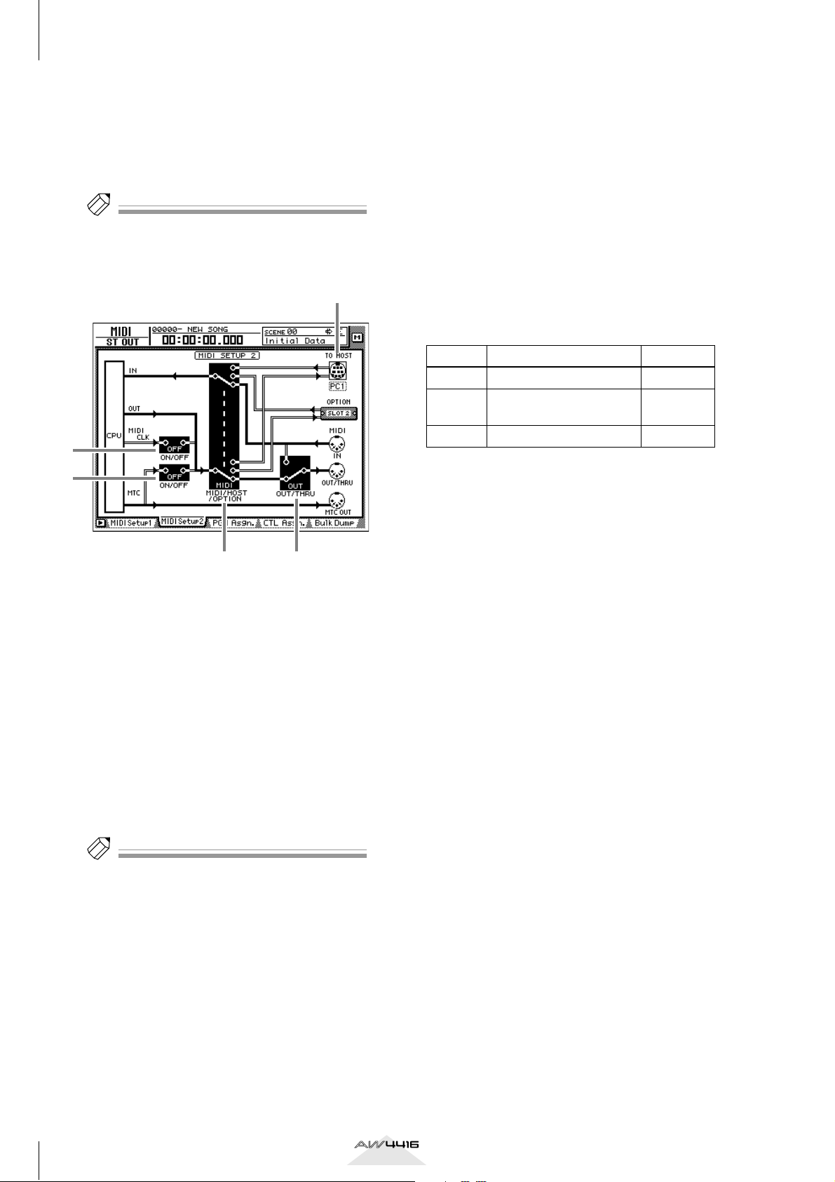
■ MIDI Setup 2 page
In this page you can select the port that will be used
for MIDI transmission and reception: MIDI OUT/
THRU connectors, TO HOST connector, or option
slot. Here you can also select the synchronization
messages that will be transmitted to external devices.
Tip!
In this page, signal routes along which MIDI messages
flow are shown by a solid line ( | ), and signal routes
along which MIDI messages do not flow are shown by
a hollow line ( || ).
3
5
4
1 2
A MIDI/HOST/OPTION switch
This selects the port that will be used to transmit/
receive MIDI messages. Move the cursor to this
area and press the [ENTER] key to cycle through
the following three settings.
• MIDI .......................The MIDI IN connector
and MIDI OUT/THRU
connector will be used.
• HOST ......................The TO HOST connector
will be used. The transmission speed is set by
the TO HOST setting.
• OPTION..................The OPTION I/O slot will
be used.
• THRU......................The MIDI messages
received at the MIDI IN
connector will be retransmitted from the OUT/
THRU connector.
• OUT........................Messages generated
within the AW4416 will
be transmitted from the
OUT/THRU connector.
C TO HOST
Set the transmission speed of the TO HOST connector according to the type of computer you are
using. Move the cursor to the TO HOST connector
graphic, and turn the [DATA/JOG] dial to select
the transmission speed from the following.
Setting Platform Speed
PC1
PC2
MAC Apple Macintosh series
*1 Select PC1 or PC2 according to the driver you are
using.
*2 Only for models that provide a modem/printer
port. On the software you are using, set the clock
to “1 MHz.”
NEC PC-9800/9821 series
IBM PC compatible, NEC
PC-9800/9821 series
*1
31.25 kbps
*2
38.4 kbps
31.25 kbps
*1
D MTC ON/OFF switch
This is an on/off switch for the MTC messages
that are sent to the MIDI OUT connector/TO
HOST connector/option slot.
E MIDI CLK ON/OFF (MIDI Clock on/off)
switch
This is an on/off switch for the MIDI Clock messages that are sent to the MIDI OUT connector/
TO HOST connector/option slot.
Tip!
The OPTION setting is valid only if an I/O card that
can transmit/receive MIDI messages (such as the
mLAN card “MY8-mLAN”; planned for availability in
the near future) is installed in option slot 2. MIDI
message transmission/reception cannot be performed via option slot 1.
B OUT/THRU switch
This switches the function of the OUT/THRU
connector. Move the cursor to this area and press
the [ENTER] key to cycle through the following
two settings.
8
Version 2.0 Manual Supplement
Using control changes to operate AW4416 parameters
In version 2.0, AW4416 parameters can be assigned
to control changes, so that AW4416 operations can be
recorded/played back on a MIDI sequencer or other
external MIDI device.
■ Assigning a parameter to a con-
trol change
Move the cursor to the CTL CHG. numeri-
2
cal box, and use the [DATA/JOG] dial to
select the control change number that you
want to assign.
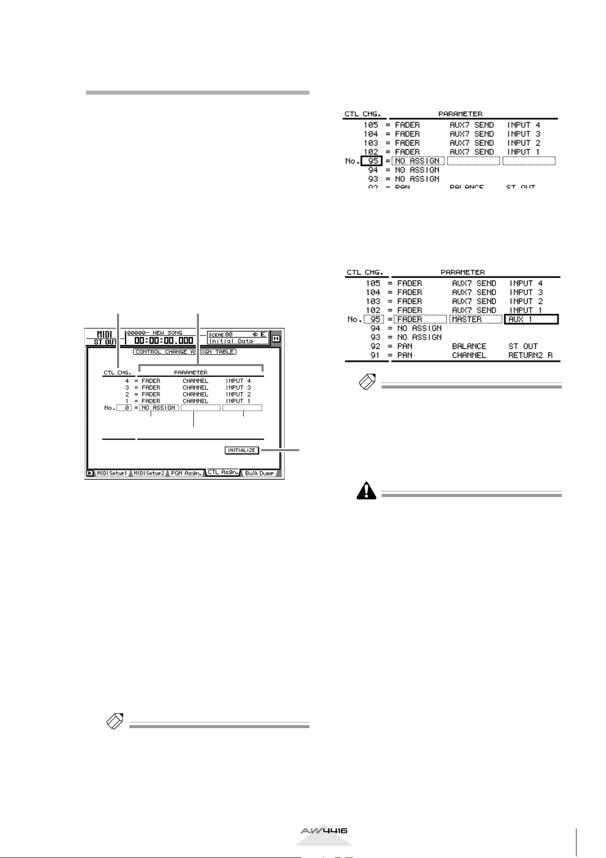
Press the [MIDI] key → [F4] (CTL Asgn.)
1
key.
The MIDI screen CTL Asgn. page added in version 2.0 will appear. In this page you can assign
AW4416 internal parameters to control change
numbers. Each part of the screen has the following function.
21
Parameter 1 Parameter 3
Parameter 2
A CTL CHG. (Control change number)
Move the cursor to this area and use the [DATA/
JOG] dial to select a control change number
from the range of 0–95 and 102–119.
B PARAMETER
This area shows the parameter that is assigned to
each control change. In the left column (parameter 1), select the type of parameter that you want
to control. In the center and right columns
(parameters 2/3), specify the values required for
that parameter. Control change numbers to
which no parameter has been assigned will be
displayed as “NO ASSIGN.”
3
Move the cursor to the various fields in the
3
PARAMETER area, and use the [DATA/JOG]
dial to set the parameter and its values.
For the available parameters and values, refer to
page 28.
Tip!
Of the parameters that can be assigned, channel
fader, AUX send, [ON] key, EQ, and pan operations
can be recorded in automix. By using automix to
record these operations, and using your MIDI
sequencer to record operations of the remaining
parameters, you can minimize the amount of MIDI
messages that are transmitted and received between
the AW4416 and your MIDI sequencer.
Control change numbers 0 and 32 are defined as
“Bank Select” (messages used to switch the voice
banks of a synthesizer, etc.). On some MIDI sequencers, bank select messages are handled differently than
other control changes, and therefore may not be suitable for use in parameter operations.
[Reference pages]
Details of the CTL Asgn. page → P.27
C INITIALIZE
This button resets the control change assignments
to the default state.
Tip!
For details on the parameters assigned to each control
change number when the AW4416 is in the default
state, refer to page 30.
Version 2.0 Manual Supplement
9
AW4416 Version 2.0 Manual Supplement
■ Recording/playing back parame-
ter operations on a MIDI
sequencer
Here’s how you can use control changes to record/
play back AW4416 parameter operations on a MIDI
sequencer.
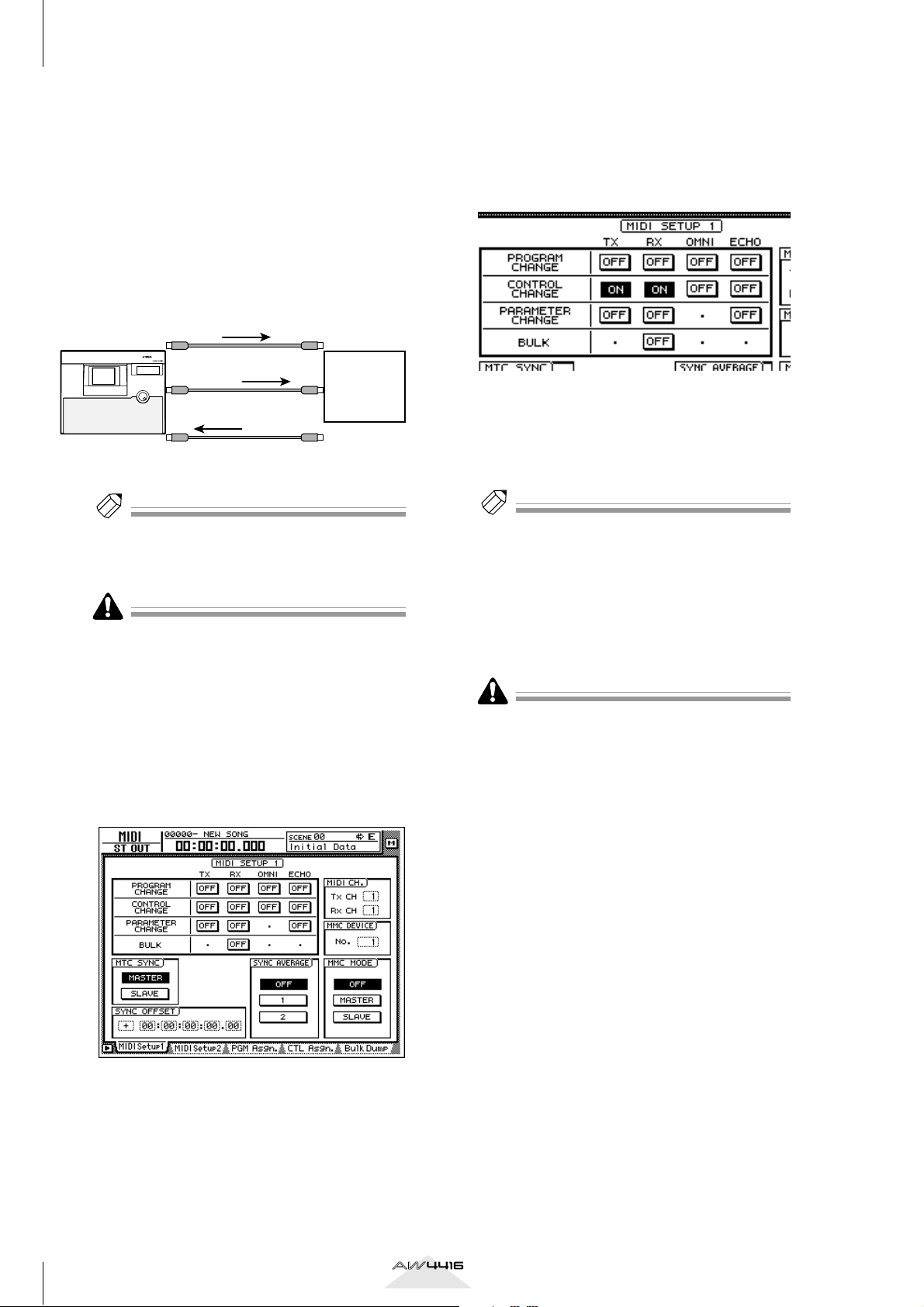
Connect the AW4416 and your MIDI
1
sequencer as shown in the following diagram, and make settings so that both
devices will operate in synchronization.
MTC master MTC slave
PROFESSIONAL AUDIO WORKSTATION
MTC OUT
connector
MIDI OUT/THRU
AW4416
connector
MIDI IN
connector
Tip!
Make sure that “MIDI” is selected as the transmission/reception port for MIDI messages, and that
“OUT” is selected as the function of the MIDI THRU/
OUT connector.
When recording/playing back control changes on
your MIDI sequencer, make sure that the MIDI Thru
function (sometimes called “Patch Thru” or “MIDI
Echo”) of your MIDI sequencer is turned off. If this
function is on, the control changes transmitted from
the AW4416 will be immediately sent back to the
AW4416, causing malfunctions.
Press the [MIDI] key → [F1] (MIDI Setup 1)
2
key.
The MIDI Setup 1 page will appear.
MTC
Control
changes
Control
changes
MIDI IN 1
connector
MIDI IN 2
connector
MIDI OUT
connector
MIDI
sequencer
With these settings, operating a parameter on the
AW4416 itself will cause the control change
assigned in the CTL Asgn. page to be transmitted.
When a control change is received from an
external device, the corresponding parameter
will change.
Move the cursor to the numerical boxes in
4
the MIDI CH. area, and use the [DATA/
JOG] dial to specify the transmit MIDI
channel and receive MIDI channel.
Tip!
• Normally you will set the transmit MIDI channel
and receive MIDI channel to the same setting.
• If the CONTROL CHANGE area OMNI button is
turned ON, control changes of all MIDI channels
will be received, regardless of the receive MIDI
channel setting.
Put your MIDI sequencer in record mode,
5
and play back the AW4416 song.
When recording parameter operations on your
sequencer, you should turn automix off (DISABLE). If
automix is on (ENABLE), the control changes corresponding to parameters recorded in the automix will
also be transmitted simultaneously.
Operate the parameters to which control
6
changes are assigned.
As the parameter is changed, the corresponding
control change will be transmitted, and recorded
on the MIDI sequencer.
Use the cursor keys and the [ENTER] key to
3
turn on the CONTROL CHANGE area TX
(transmit) button and RX (receive) button.
10
Version 2.0 Manual Supplement
When you are finished recording, press the
7
[STOP] key.
Put your MIDI sequencer in playback-ready
8
mode.
Locate to a point earlier than where you
9
begin recording parameter operations, and
play back the song.
When control changes from the MIDI sequencer
are received by the AW4416 while it is running,
the corresponding parameter will change.
Using parameter changes to perform AW4416 operations
In version 2.0, a type of system exclusive message
called “parameter changes” can be used (instead of
control changes) to operate internal parameters of the
AW4416. Here’s how to record/play back parameter
changes on your MIDI sequencer.
Make settings on the AW4416 and on your
1
MIDI sequencer so that they will operate in
synchronization using MTC.
For details on connections, refer to page 10.
Tip!
Make sure that “MIDI” is selected as the transmission/reception port for MIDI messages, and that
“OUT” is selected as the function of the MIDI THRU/
OUT connector.
Operate the desired parameters on the
5
AW4416.
As the parameter is changed, the corresponding
parameter change will be transmitted, and
recorded on the MIDI sequencer.
When you are finished recording, press the
6
[STOP] key.
Put your MIDI sequencer in playback-ready
7
mode.
On the AW4416, locate to a point earlier
8
than where you begin recording parameter
operations, and play back the song.
The MIDI sequencer will begin playback in synchronization with the AW4416. When parameter
changes from the MIDI sequencer are received
by the AW4416, the corresponding parameter
will change.
When recording/playing back parameter changes on
your MIDI sequencer, make sure that the MIDI Thru
function of your MIDI sequencer is turned off. If this
function is on, the parameter changes transmitted
from the AW4416 will be immediately sent back to
the AW4416, causing malfunctions.
Press the [MIDI] key → [F1] (MIDI Setup 1)
2
key.
The MIDI Setup 1 page will appear.
Use the cursor keys and the [ENTER] key to
3
turn on the PARAMETER CHANGE area TX
(transmit) button and RX (receive) button.
With these settings, operating a parameter on the
AW4416 itself will cause the corresponding
parameter change to be transmitted. When a
parameter change is received from an external
device, the corresponding parameter will
change.
Transmitting internal AW4416 settings via MIDI (Bulk Dump)
In version 2.0, settings of the MIDI screen and the
contents of the various libraries can be converted into
MIDI data (bulk data) and transmitted to an external
device such as a MIDI sequencer.
Connect the AW4416’s MIDI OUT/THRU
1
connector to the MIDI IN connector of the
external MIDI device, and the AW4416’s
MIDI IN connector to the MIDI OUT connector of the external MIDI device.
Press the [MIDI] key → [F5] (Bulk Dump)
2
key.
The MIDI screen Bulk Dump page will appear.
The various areas of the screen have the following functions.
Tip!
• The parameter change messages corresponding to
each parameter are fixed, and cannot be changed.
• For details on the parameters that can be controlled
by parameter changes, refer to page 47.
Put your MIDI sequencer in record mode,
4
and play back the AW4416 song.
1
A CATEGORY
Move the cursor to the category of information
that you want to transmit as bulk data, and press
the [ENTER] key to select that category.
Version 2.0 Manual Supplement
2 3 4
11
AW4416 Version 2.0 Manual Supplement
If you select a category from the right column of
buttons (SCENE MEM.–REMOTE), move the cursor to the column at the far right, and turn the
[DATA/JOG] dial to select the content within that
category that will be transmitted.
Category Values
SETUP MEM.
PGM. TABLE
CTL. TABLE
SCENE MEM. The specified scene memory
PATCH LIBRARY The specified patch library
CH LIBRARY The specified channel library
EQ LIBRARY The specified EQ library
DYN. LIBRARY The specified dynamics library
EFF. LIBRARY The specified effect library
AUTO MIX The specified automix
MIDI REMOTE Settings of the REMOTE screen
AW4416 settings other than the
following items
Settings of the MIDI screen PGM
ASGN. page
Settings of the MIDI screen CTL
ASGN. page
—
—
—
01–96 Scene number 1–96
EDIT BUFFER Current scene (current mixer settings)
ALL All scene memories + current scene
01–20 Library number 1–20
ALL All patch libraries
02–64 Library number 2–64
ALL All channel libraries
41–128 Library number 41–128
ALL All EQ libraries
41–128 Library number 41–128
ALL All dynamics libraries
42–128 Library number 42–128
ALL All effect libraries
1–16 Memory number 1–16
BUFFER Current automix
ALL All automixes + current automix
REMOTE A–
REMOTE B
ALL Settings of all pages of the REMOTE screen
Settings of the REMOTE A (REMOTE A 1-8/9-16
pages) or B (REMOTE B 1-8/9-16 pages)
B REQUEST button
When you move the cursor to this button and
press the [ENTER] key, a “bulk dump request”
message requesting the bulk dump data selected
in 1 will be transmitted from the MIDI OUT
connector/TO HOST connector/option slot.
This button is used when two AW4416 units are
connected by their respective MIDI IN/OUT connectors, and you want to copy scene memory or
library data from one unit to the other.
C TRANSMIT button
When you move the cursor to this button and
press the [ENTER] key, the bulk dump will begin.
D INTERVAL
This adjusts the interval that will be left between
data blocks when bulk data is transmitted. You
can set the interval in 1 millisecond units over a
range of 0–300 milliseconds (default= 0).
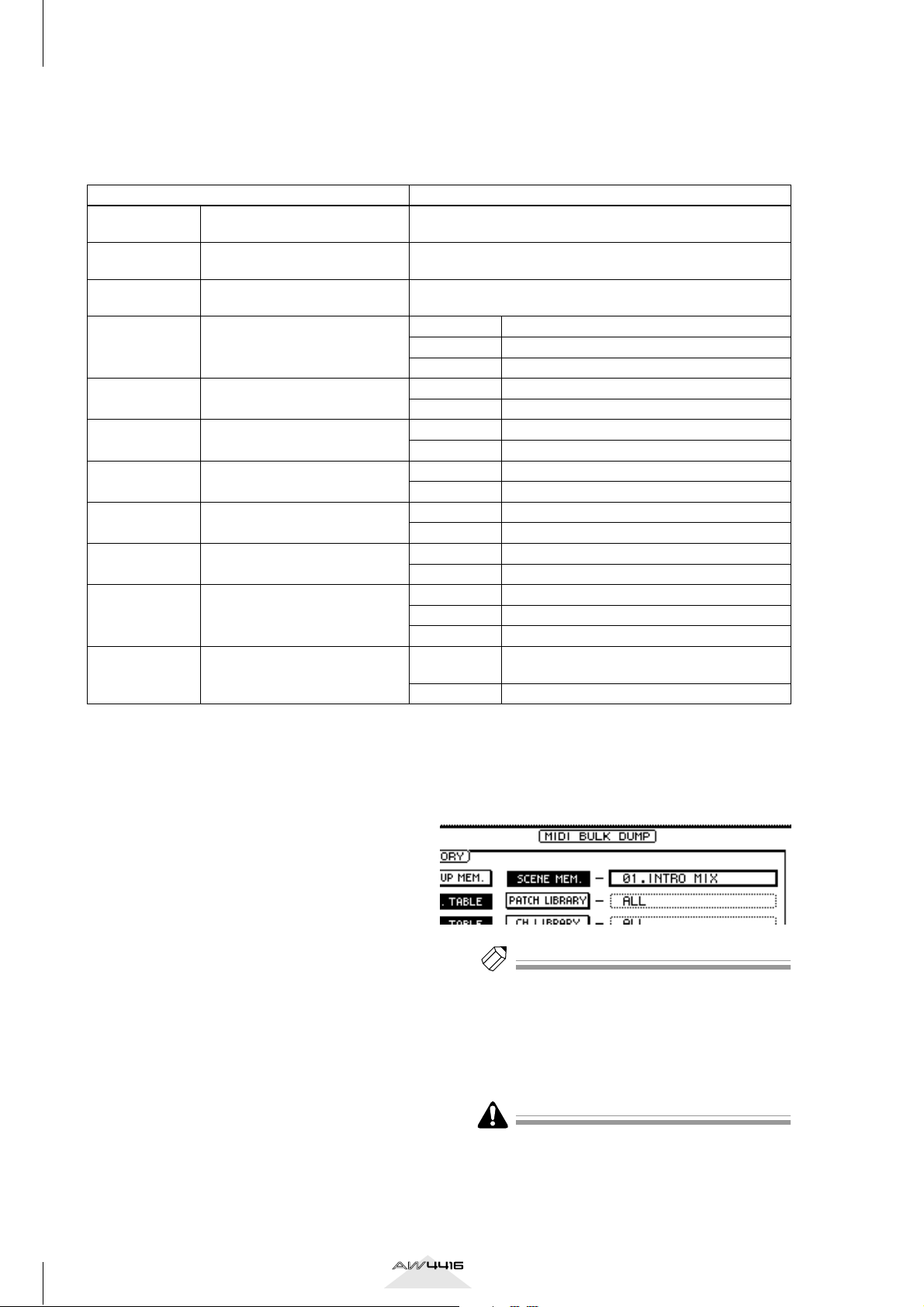
Move the cursor to the button for the bulk
3
data that you want to transmit, and press
the [ENTER] key.
The corresponding button will be turned on, and
will be selected for bulk dump.
If you selected a SCENE MEM.–REMOTE
4
button, move the cursor to the numerical
box at the right of the button, and use the
[DATA/JOG] dial to select the internal settings that you want to transmit.
Tip!
If you move the cursor to the ALL button located at
the lower left of CATEGORY and press the [ENTER]
key, all settings that can be bulk-dumped will be
selected.
Put your MIDI sequencer in record-ready
5
mode.
When recording bulk data on your MIDI sequencer,
make sure that the MIDI Thru function (sometimes
called “Patch Thru” or “MIDI Echo”) of your MIDI
sequencer is turned off. If this function is on, the bulk
data transmitted from the AW4416 will be immediately sent back to the AW4416, causing malfunctions.
12
Version 2.0 Manual Supplement
Move the cursor to the TRANSMIT button,
6
and press the [ENTER] key.
The bulk dump will begin. While the bulk dump
is occurring, a popup window will appear, indicating the current state of progress.
Tip!
You can abort the bulk dump by pressing the [ENTER]
key while the popup window is displayed.
• If an error occurs during the bulk dump, try increasing the INTERVAL setting to leave a longer pause
between the data blocks that are transmitted.
• The time required for executing the bulk dump will
depend on the category that is selected and on the
content of the data. Particularly in the case of automix, a significantly long time may be required
depending on the amount of data that is recorded.
To receive previously-stored bulk data,
7
press the [MIDI] key → [F1] (MIDI Setup 1)
key.
The MIDI screen MIDI Setup 1 page will appear.
Newly added MIDI Remote function
The new MIDI Remote function lets you use faders 1–
16 and [ON] keys 1–16 to control a connected external MIDI device.
■ About the MIDI Remote function
“MIDI Remote” is a function that lets you assign specific MIDI messages to faders 1–16 and [ON] keys 1–
16, so that these messages will be transmitted when
you operate the corresponding fader or [ON] key. The
following types of messages can be assigned.
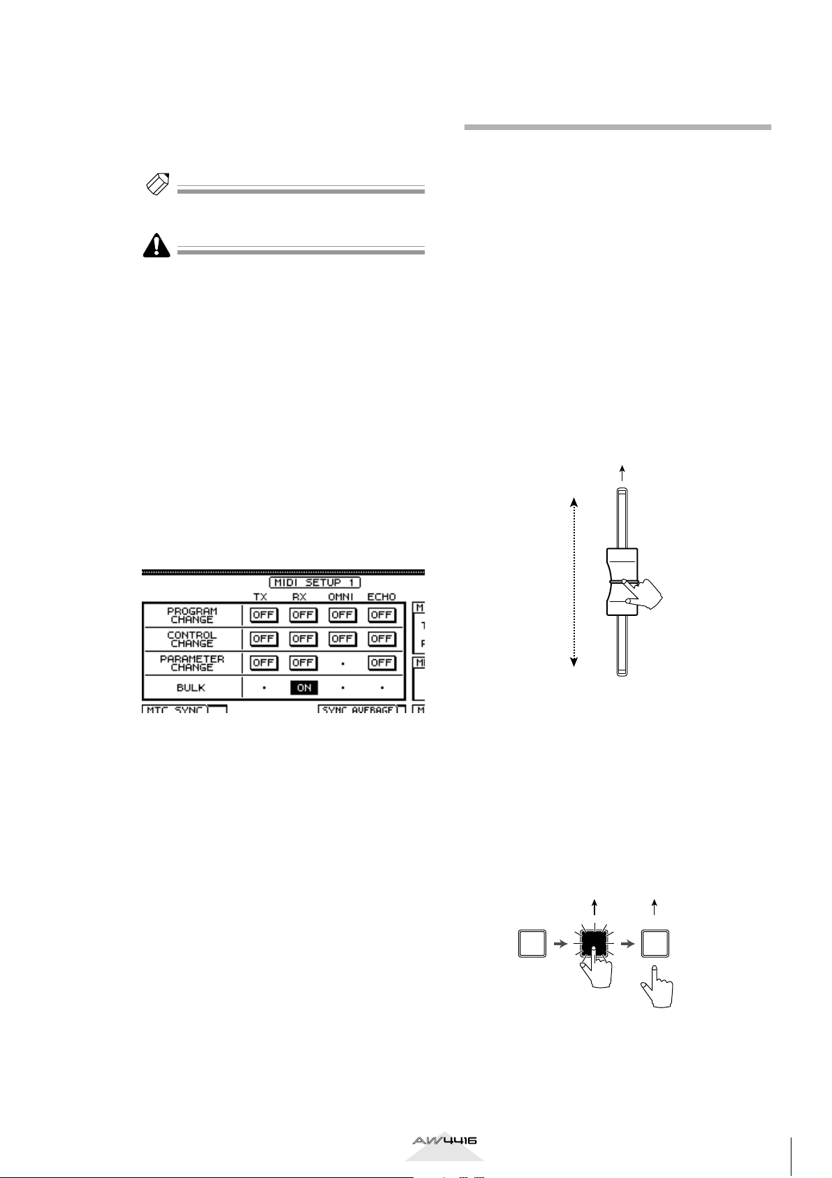
●Messages that can be assigned to faders
MIDI messages whose value changes in a range of 0–
127 can be assigned to faders. For example if you
assign control change #7 (Volume) to a fader and
specify a range of 0–127 as the control change value,
operating the fader will control the volume of a MIDI
tone generator.
Control change number 7
Move the cursor to the BULK area RX
8
(Receive) button, and press the [ENTER]
key.
The RX button will be turned on, and the
AW4416 will be ready to receive bulk data.
Make sure that the transport of the
9
AW4416 is stopped, and transmit bulk data
from your MIDI sequencer.
When all bulk data has been received, the corresponding settings and/or libraries will be
updated.
[Reference pages]
Details on the Bulk Dump page → P.31
Value= 127
Value= 0
●Messages that can be assigned to [ON] keys
MIDI messages whose value switches to 0 or 127 can
be assigned to [ON] keys. For if you assign control
change #64 (Hold) to an [ON] key and make settings
so that the value switches to either 0 or 127, turning
the [ON] key on (lit) will transmit control change #64
with a value of 127 (Hold On), and turning it off (dark)
will transmit control change #64 with a value of 0
(Hold Off).
Control change
number 64
(value=127)
Transmitted Transmitted
Transmitted
Control change
number 64
(value=0)
Version 2.0 Manual Supplement
ON ONON
13
AW4416 Version 2.0 Manual Supplement
You can also make settings so that a MIDI message
with a fixed value is transmitted only when the [ON]
key is turned on (lit). For example if you assign a program change #1 message, the corresponding program
change message will be transmitted each time you
turn the [ON] key on.
Program change
number 1
Transmitted Transmitted
ON ON ONON ON
Program change
number 1
■ Using the MIDI Remote function
with the default settings
With the default settings, MIDI messages are already
assigned to some of the faders and [ON] keys. Here’s
how to use the MIDI Remote function with the default
settings.
Tip!
For the MIDI messages that are assigned by default to
the faders/[ON] keys by the MIDI Remote function,
refer to page 35.
Connect the AW4416’s MIDI OUT/THRU
1
connector to the MIDI IN connector of the
external device.
At this time, make sure that the MIDI Setup 2
page OUT/THRU switch is set to “OUT.”
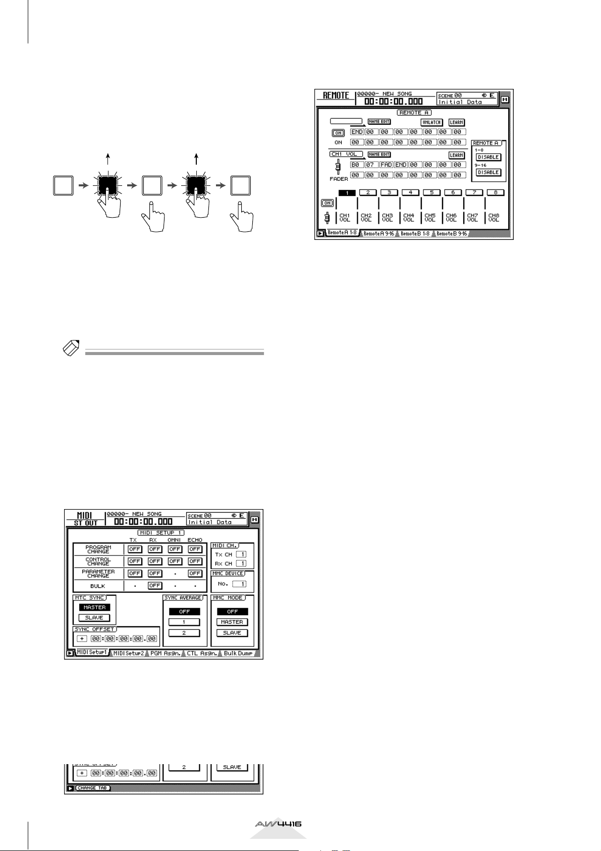
Press the [MIDI] key.
2
The MIDI screen will appear.
In this state, you can press the [F1] key to access
the REMOTE screen.
The mixing layer that had been selected until
now will be cancelled, and a special mixing
layer called Remote A/Remote B will be in effect.
Remote A and Remote B are mixing layers that
let you use faders 1–16 and [ON] keys 1–16 to
transmit MIDI messages. Settings and operations
are performed in the following four pages.
● Remote A 1-8
Assign MIDI messages to Remote A faders 1–8/
[ON] keys 1–8
● Remote A 9-16
Assign MIDI messages to Remote A faders 9–16/
[ON] keys 9–16
● Remote B 1-8
Assign MIDI messages to Remote B faders 1–8/
[ON] keys 1–8
● Remote B 9-16
Assign MIDI messages to Remote B faders 9–16/
[ON] keys 9–16
Hold down the [SHIFT] key and press the
3
[F1] key to switch tabs.
In the various pages of the MIDI screen, the
lower part of the display will show the tabs as
long as you hold down the [SHIFT] key, as shown
below.
Press one of the [F1]–[F4] keys to select the
4
mixing layer that you want to operate.
If you press the [F1]/[F2] keys, you will be able to
operate Remote A. If you press the [F3]/[F4] keys,
you will be able to operate Remote B. (In the
example screen shown above, the Remote A 1-8
page is selected.)
In the Remote A area in the right side of
5
the display, move the cursor to the DISABLE buttons for 1-8/9-16, and press the
[ENTER] key.
The button indication will change to “ENABLE,”
and the corresponding faders/[ON] keys can be
used for the MIDI Remote function.
If you set both the 1-8 and the 9-16 buttons to
“ENABLE,” remote operations can be performed
using all faders 1–16/[ON] keys 1–16 of the
same mixing layer.
14
Version 2.0 Manual Supplement
Operate faders 1–16/[ON] keys 1–16.
1
2
3
6
The MIDI messages assigned to the corresponding fader/[ON] key will be transmitted from the
MIDI OUT/THRU connector.
• In the MIDI Setup 1 page, make sure that the ECHO
button in the CONTROL CHANGE area is turned
off. If the ECHO button is turned on, control
changes received from the external device will be
re-transmitted back to the external device, causing
malfunctions.
• In the MIDI Setup 2 page, make sure that the MIDI
OUT/THRU switch is set to OUT.
• The TX, RX, and OMNI buttons in the CONTROL
CHANGE area of the MIDI Setup 1 page will not
affect MIDI Remote operations.
Press the [MIDI] key.
2
Tip!
• Even when the REMOTE screen is displayed, the
function of the faders and [ON] keys of the stereo
output channel will not change.
• The Remote A/Remote B fader positions and [ON]
key on/off status can be saved in a scene.
• Fader and [ON] key operations can also be recorded
in automix. By using automix to record operations
separately in each page, you can perform up to 32
channels of fader/[ON] key operations.
■ Assigning a MIDI message to a
fader
The MIDI Remote function lets you assign a MIDI
message of up to 16 bytes to each fader/each [ON]
key.
A message can be assigned in one of two ways. You
can input the desired message manually, one byte at a
time. Or you can capture a MIDI message received
from the MIDI IN connector/TO HOST connector/
option slot, and assign it either without change or
after editing it.
Here we will explain how to transmit a modulation
wheel message (control change #1) from a synthesizer
to the AW4416, and assign it to a desired fader.
Connect the MIDI OUT/THRU connector of
1
the AW4416 to the MIDI IN connector of
your synthesizer, and the MIDI IN connector of the AW4416 to the MIDI OUT connector of your synthesizer.
PROFESSIONAL AUDIO WORKSTATION
MIDI IN
connector
MIDI OUT
connector
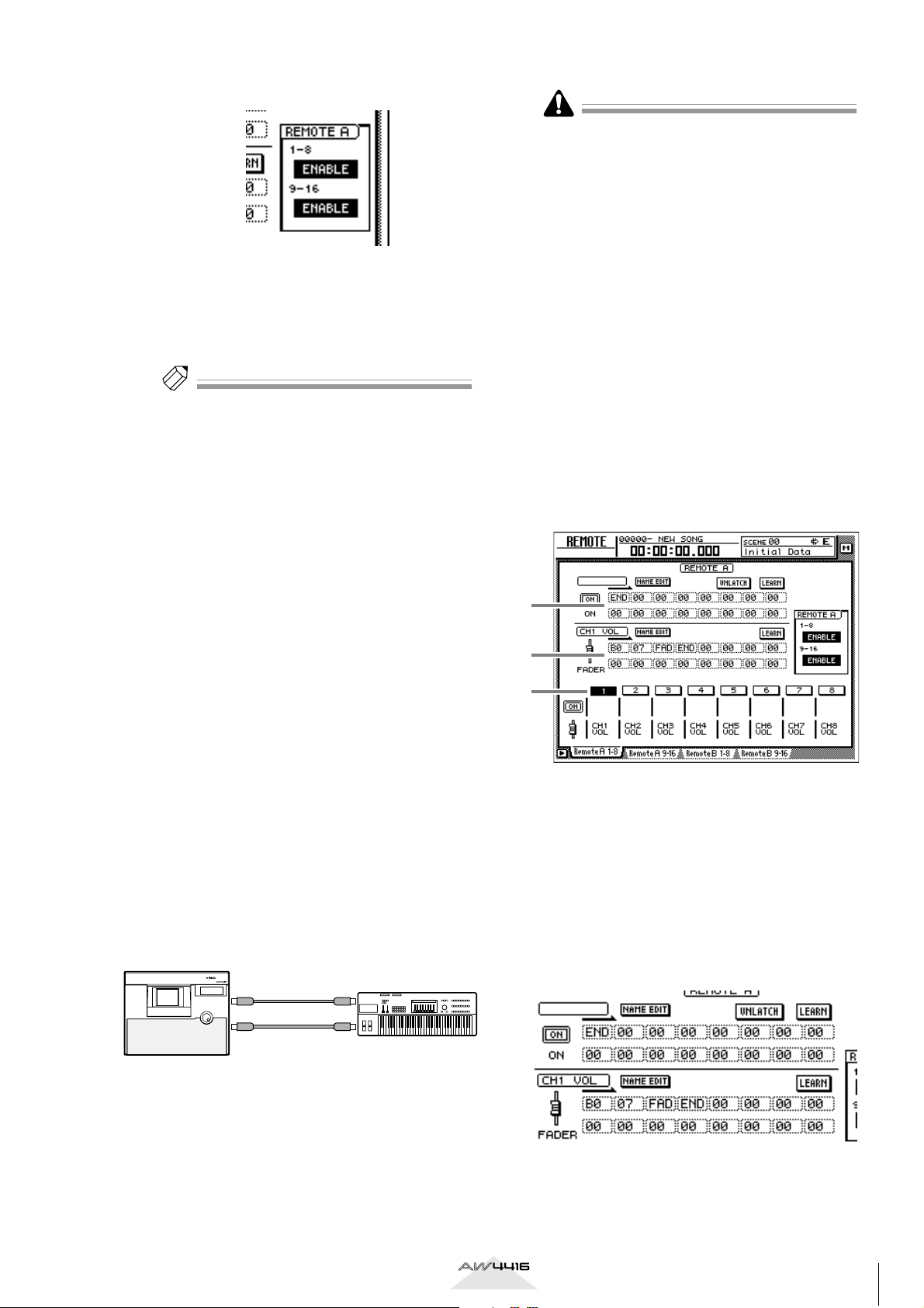
Hold down the [SHIFT] key and press the
3
[F1] key to access the REMOTE screen.
Press one of the [F1]–[F4] keys to display
4
the fader/[ON] key to which you want to
assign a MIDI message.
The Remote A 1-8 page is selected in this example.
A MIDI message assigned to the [ON] key
B MIDI message assigned to the fader
C Currently selected channel number
Press the [SEL] key for the channel to
5
which you want to assign a MIDI message.
Areas 1 and 2 will show the MIDI messages
that are assigned to the fader and [ON] key of
that channel.
AW4416
MIDI OUT/THRU
connector
MIDI IN
connector
MIDI keyboard
Version 2.0 Manual Supplement
15
 Loading...