

Page 1
PROFESSIONAL AUDIO WORKSTATION
PROFESSIONAL AUDIO WORKSTATION
Owner’s Manual
Owner’s Manual
Keep This Manual For Future Reference.
Keep This Manual For Future Reference.
E
Page 2
FCC INFORMATION (U.S.A.)
1. IMPORTANT NOTICE: DO NOT MODIFY THIS UNIT! This product, when installed as indicated in the instructions contained in this manual, meets FCC
requirements. Modifications not expressly approved by Yamaha may void your authority, granted by the FCC, to use the product.
2. IMPORTANT: When connecting this product to accessories and/or another product use only high quality shielded cables. Cable/s supplied with this product MUST
be used. Follow all installation instructions. Failure to follow instructions could void your FCC authorization to use this product in the USA.
3. NOTE: This product has been tested and found to comply with the requirements listed in FCC Regulations, Part 15 for Class “B” digital devices. Compliance with
these requirements provides a reasonable level of assurance that your use of this product in a residential environment will not result in harmful interference with
other electronic devices. This equipment generates/uses radio frequencies and, if not installed and used according to the instructions found in the users manual, may
cause interference harmful to the operation of other electronic devices. Compliance with FCC regulations does not guarantee that interference will not occur in all
installations. If this product is found to be the source of interference, which can be determined by turning the unit “OFF” and “ON”, please try to eliminate the
problem by using one of the following measures: Relocate either this product or the device that is being affected by the interference. Utilize power outlets that are on
different branch (circuit breaker or fuse) circuits or install AC line filter/s. In the case of radio or TV interference, relocate/reorient the antenna. If the antenna lead-in
is 300 ohm ribbon lead, change the lead-in to coaxial type cable. If these corrective measures do not produce satisfactory results, please contact the local retailer
authorized to distribute this type of product. If you can not locate the appropriate retailer, please contact Yamaha Corporation of America, Electronic Service
Division, 6600 Orangethorpe Ave, Buena Park, CA 90620
The above statements apply ONLY to those products distributed by Yamaha Corporation of America or its subsidiaries.
ADVARSEL!
Lithiumbatteri—Eksplosionsfare ved fejlagtig
håndtering. Udskiftning må kun ske med batteri
af samme fabrikat og type. Levér det brugte
batteri tilbage til leverandoren.
VARNING
Explosionsfara vid felaktigt batteribyte. Använd
samma batterityp eller en ekvivalent typ som
rekommenderas av apparattillverkaren.
Kassera använt batteri enligt fabrikantens
instruktion.
VAROITUS
Paristo voi räjähtää, jos se on virheellisesti
asennettu. Vaihda paristo ainoastaan
laitevalmistajan suosittelemaan tyyppiin. Hävitä
käytetty paristo valmistajan ohjeiden
mukaisesti.
CAUTION
RISK OF ELECTRIC SHOCK
DO NOT OPEN
CAUTION: TO REDUCE THE RISK OF
ELECTRIC SHOCK, DO NOT REMOVE
COVER (OR BACK). NO USER-SERVICEABLE
PARTS INSIDE. REFER SERVICING TO
QUALIFIED SERVICE PERSONNEL.
The above warning is located on the
rear of the unit.
WARNING: THIS APPARATUS MUST BE EARTHED
IMPORTANT
THE WIRES IN THIS MAINS LEAD ARE COLOURED IN
ACCORDANCE WITH THE FOLLOWING CODE:
GREEN-AND-YELLOW : EARTH
BLUE : NEUTRAL
BROWN : LIVE
As the colours of the wires in the mains lead of this apparatus may
not correspond with the coloured markings identifying the terminals in
your plug, proceed as follows:
The wire which is coloured GREEN and YELLOW must be
connected to the terminal in the plug which is marked by the letter E
or by the safety earth symbol or coloured GREEN and YELLOW.
The wire which is coloured BLUE must be connected to the terminal
which is marked with the letter N or coloured BLACK.
The wire which is coloured BROWN must be connected to the
terminal which is marked with the letter L or coloured RED.
* This applies only to products distributed by YAMAHA KEMBLE
MUSIC (U.K.) LTD.
• Explanation of Graphical Symbols
The lightning flash with arrowhead symbol
within an equilateral triangle is intended to
alert the user to the presence of uninsulated
“dangerous voltage” within the product’s
enclosure that may be of sufficient magnitude to constitute a risk of electric shock to
persons.
The exclamation point within an equilateral triangle is intended to alert the user to
the presence of important operating and
maintenance (servicing) instructions in the
literature accompanying the product.
Page 3

NEDERLAND THE NETHERLANDS
● Dit apparaat bevat een lithium batterij voor geheugen
back-up.
● Raadpleeg uw leverancier over de verwijdering van de
batterij op het moment dat u het apparaat ann het einde
van de levensduur afdankt of de volgende Yamaha Service
Afdeiing:
Yamaha Music Nederland Service Afdeiing
Kanaalweg 18-G, 3526 KL UTRECHT
Tel. 030-2828425
● Gooi de batterij niet weg, maar lever hem in als KCA.
● This apparatus contains a lithium battery for memory
back-up.
● For the removal of the battery at the moment of the
disposal at the end of the service life please consult your
retailer or Yamaha Service Center as follows:
Yamaha Music Nederland Service Center
Address: Kanaalweg 18-G, 3526 KL
UTRECHT
Tel: 030-2828425
● Do not throw away the battery. Instead, hand it in as small
chemical waste.
Page 4

Important
Important
Read the following before operating the AW2816
■
Warnings
• Do not place a container with liquid or small
metal objects on top of this unit. Liquid or metal
objects inside this unit are a fire and electrical
shock hazard.
• Do not allow water to enter this unit or allow the
unit to become wet. Fire or electrical shock may
result.
• Connect this unit’s power cord only to an AC outlet of the type stated in this Owner’s Manual or as
marked on the unit. Failure to do so is a fire and
electrical shock hazard.
• Do not scratch, bend, twist, pull, or heat the
power cord. A damaged power cord is a fire and
electrical shock hazard.
• Do not place heavy objects, including this unit, on
top of the power cord. A damaged power cord is a
fire and electrical shock hazard. In particular, be
careful not to place heavy objects on a power cord
covered by a carpet.
• To avoid possible electrical shock, do not install
an I/O card, hard disk, or CD-RW drive in the unit
while the power cable is connected to the AC outlet.
• Use the ground connector on the rear panel to
securely ground the device. If the device is not
grounded, you may suffer a dangerous electrical
shock.
• If you notice any abnormality, such as smoke,
odor, or noise, or if a foreign object or liquid gets
inside the unit, turn it off immediately. Remove the
power cord from the AC outlet. Consult your
dealer for repair. Using the unit in this condition is
a fire and electrical shock hazard.
• Should this unit be dropped or the cabinet be
damaged, turn the power switch off, remove the
power plug from the AC outlet, and contact your
dealer. If you continue using the unit without
heeding this instruction, fire or electrical shock
may result.
• If the power cord is damaged (i.e., cut or a bare
wire is exposed), ask your dealer for a replacement. Using the unit with a damaged power cord
is a fire and electrical shock hazard.
• Do not modify the unit. Doing so is a fire and electrical shock hazard.
• Do not apply force to, disassemble, or modify the
I/O card, the PC board of the hard disk, or the connectors on the unit. Otherwise, malfunction, fire,
or electrical shock may result.
• If lightning begins to occur, turn off the power
switch of the unit as soon as possible, and unplug
the power cable plug from the electrical outlet.
• If there is a possibility of lightning, do not touch
the power cable plug if it is still connected. Doing
so may be an electrical shock hazard.
■
Cautions
• This unit has ventilation holes at the bottom to prevent the internal temperature rising too high. Do
not block them. Blocked ventilation holes are a
fire hazard.
• Hold the power cord plug when disconnecting it
from an AC outlet. Never pull the cord. A damaged power cord is a potential fire and electrical
shock hazard.
• Do not touch the power plug with wet hands.
Doing so is a potential electrical shock hazard.
• Always touch a well-grounded metal surface or
the like to fully discharge any static electric charge
on your body and clothing before handling an I/O
card or hard disk.
Neglecting this precaution can cause damage to
the unit from static electricity.
• Be careful not to touch the leads (metal feet) on
the rear side when handling an I/O card or hard
disk. Touching the leads can cause contact defects.
• Use only the included power supply cable for this
unit. Using other types may be a fire hazard.
■
Operating Notes
• The digital circuits of this unit may induce a slight
noise into nearby radios and TVs. If noise occurs,
relocate the affected equipment.
• Using a mobile telephone near this unit may
induce noise. If noise occurs, use the telephone
away from the unit.
• XLR-type connectors are wired as follows:
pin 1: ground, pin 2: hot (+), and pin 3: cold (–).
• Insert TRS phone jacks are wired as follows:
sleeve: ground, tip: send, and ring: return.
• If the message “LOW BATTERY” appears when
you turn on this unit, contact your dealer as soon
as possible about replacing the internal data
backup battery.
We recommend that you save the data on CD-RW
drive or external SCSI device before replacing the
battery.
• The performance of components with moving
contacts, such switches, rotary controls, faders,
and connectors, deteriorates over time. The rate of
deterioration depends on the operating environment and is unavoidable. Consult your dealer
about replacing defective components.
iv
Page 5

v
Handling the CD-R/RW media
Please observe the following points when handling
the disk.
Failure to do so may cause problems such as the
recorded data being lost, the drive to malfunction, or
the printed label to become blurred.
• Do not place the disk in locations of direct sunlight, high temperature, or high humidity.
• Do not touch either surface of the disk.
• Hold the disk at the edges. Gently wipe dust or
dirt off of the recording surface of the disk.
• Do not wipe the disk with chemicals or detergents.
• Do not bend or drop the disk.
• Use an air duster or cleaner to remove dust. Vigorously rubbing the surface of the disk with a dry
cloth may scratch the disk.
• Do not write on the disk or affix labels to it.
Storing produced data
Produced data can be lost due to breakdown or mistaken operation. We recommend that you store all
important data on CD-R or CD-RW disks or other
external storage medium.
Responsibility for loss of data,
etc.
• Yamaha will accept no responsibility for any damages (including consequential or incidental)
incurred by the customer or any third party as a
result of loss or impairment of the data stored on
the CD-R media, regardless of whether such loss
could have been or actually was foreseen by
Yamaha.
• Nor does Yamaha guarantee the media against any
defect that may render it unusable.
Cautions for handling optional
equipment
• For inquiries concerning I/O card, hard disk, or
CD-RW drive handling, please consult your
Yamaha dealer.
• Always switch off the power for the main unit and
all peripherals, unplug the power cord for the
main unit from the outlet, then disconnect the
cables connecting the main unit with the peripherals before starting installation work.
• Wear thick gloves when working on this equipment to avoid cutting your hands on metal fittings
or the like on the main unit, I/O card, hard disk, or
CD-RW drive.
• Always touch a well-grounded metal surface or
the like to fully discharge any static electric charge
on your body and clothing before starting to work
on this equipment.
• Take extreme care to avoid touching any terminals
or board surface parts.
• In order to protect the electronic circuits of the I/O
card, hard disk, CD-RW drive, etc. from damage
due to static electricity, when handling any of this
equipment, take the most extreme care to avoid
touching IC leads or other electronic parts.
• Be careful not to drop any screws into the main
unit. If you switch the power on with a dropped
screw still in the main unit, the main unit may
malfunction or break down. If a dropped screw
can not be retrieved, consult your Yamaha dealer.
• If the hard disk or CD-RW drive breaks down, contact the store where you purchased that equipment.
Except for duplication for personal use or when there
is no copyright problem, the duplication or transfer of
commercially sold music/sound data without the permission of the copyright holder is prohibited. When
using this equipment, please consult with a copyright
specialist.
■
Warning
The Yamaha Professional Audio Workstation is
designed to be used professionally and responsibly by
recording industry professionals. The reproduction,
distribution, or, in some instances, the public performance, of all or a portion of a sound recording or
musical composition protected by copyright, without
having obtained a proper license from the relevant
copyright holders, may constitute copyright infringement and may otherwise violate copyright laws and
other laws. In addition, laws (such as the Audio Home
Recording Act and the Digital Millennium Copyright
Act in USA) contain certain restrictions and requirements that may apply to your use of works protected
by copyright and related information and data that
may accompany such works. Violation of such laws
may result in civil remedies and, in some cases, criminal liability.
Because violations of copyright laws may be serious
offenses, you should consult a lawyer familiar with
the law of copyright, including all laws that may be
applicable to your use of the Workstation (such as the
Audio Home Recording Act and the Digital Millennium Copyright Act in USA), if you have any questions regarding your intended use of all or parts of
sound recordings or musical compositions protected
by copyright.
Page 6

Table of contents
Table of contents
Before you begin .....................1
Checking the included items ...................1
Installing an internal hard disk ................2
About the internal hard disk..........................2
Installation ....................................................2
Installing a CD-RW drive.........................4
About the CD-RW drives ..............................4
CD-RW drive settings ...................................4
Installation procedure ...................................5
Removing the transport protection pad...7
Manual eject (emergency disc removal) .......7
Attaching an external SCSI device...........8
About external SCSI devices .........................8
Connection procedure..................................8
Installing I/O card .................................10
About I/O cards ..........................................10
Installation procedure .................................10
Please observe the following points.......11
Turning the power on .................................11
Setting the internal clock ............................11
Turning the power off .................................12
Chapter1
Top panel...............................................13
Analog input/output section........................13
WORK NAVIGATE section.........................14
UNIT section ..............................................14
MIXER section.............................................14
FADER MODE section................................15
MIXING LAYER section ..............................15
Fader section ..............................................16
Display section ...........................................17
REC TRACK SELECT section .......................18
RECORDER section ....................................18
AUTOMATION section ..............................19
SCENE MEMORY section ...........................19
CURSOR/JOG&SHUTTLE section...............19
LOCATE section..........................................20
Transport section ........................................21
Rear panel..............................................22
Front panel ............................................24
Chapter2
Parts and their functions 13
Welcome to the world
of the AW2816 ..........25
Features of the AW2816........................25
Mixer section ..............................................25
Recorder section.........................................25
CD-RW drive (option).................................26
Other features .............................................26
Signal flow within the AW2816.............27
Input patch .................................................27
Input channels 1–8 .....................................28
Return channels 1/2....................................29
Recorder input patch ..................................29
Monitor channels 1–16...............................30
Digital cascade connection.........................30
Oscillator....................................................30
Stereo output channel.................................31
Buses 1–8 ...................................................31
AUX buses 1–6 ...........................................31
Output patch ..............................................32
Internal effects 1/2 ......................................32
Monitor output/headphone output..............32
The track structure of the AW2816.......33
Audio tracks................................................33
Virtual tracks...............................................33
The stereo track ..........................................33
About the display...................................34
Cursor.........................................................34
Buttons........................................................35
Knobs/faders/numerical boxes ....................35
Tabs ............................................................35
Basic operation of the AW2816 ............36
Accessing screens and pages ......................36
Switching a button on/off............................36
Editing the value of a fader/knob/numerical
box ............................................................36
Using the additional function buttons.........37
Inputting text...............................................37
Selecting a channel.....................................38
Chapter3
Let’s record on the
AW2816 .................... 41
Connections and setup ..........................41
Making connections ...................................41
Creating a new song ...................................42
Word clock settings ....................................44
Recording the first track ........................46
Setting the input level .................................46
Pairing two channels...................................47
Patching input signals to recorder inputs ....48
Adjusting the monitor level.........................50
Recording ...................................................51
Recording additional tracks
(Overdubbing)......................................52
Setting the input level .................................52
Patching the input signal to the recorder input
Adjusting the monitor level.........................54
Applying the equalizer to the input signal...54
Applying the dynamics processor to the input
signal.........................................................55
Recording ...................................................57
Mixing to the stereo track (Mixdown) ...58
Adjusting the mix balance ..........................58
Using the internal effects.............................59
Recording on the stereo track .....................60
Saving your song....................................62
Advanced techniques on the AW2816 ..63
Manually re-recording only a specific area
(Manual Punch-in/out)...............................63
Automatically re-recording only a specific area
(Auto Punch-in/out) ...................................64
Switching virtual tracks...............................66
Operating multiple faders together
(Fader Groups)...........................................67
Operating multiple [ON] keys together
(Mute Groups) ...........................................68
Using the Solo function ..............................69
Chapter4
Assigning signals to input channels/return
channels (Input Patch)..........................71
Assigning signals to the recorder inputs
(Recorder Input Patch).........................73
Assigning signals to output jacks/output
channels (Output Patch) ......................74
Using the patch library ..........................76
Storing the patching settings to the library ..76
Recalling patching settings from the library 77
Inserting an external effect into a channel
Quickly assigning input signals to tracks
(Quick Rec) ..........................................80
Chapter5
Input/output patching 71
Using the internal
.........................52
.......................78
effects ....................... 83
About the internal effects ......................83
Using AUX send/return to apply an effect
Check the patching.....................................84
Recalling an effect program from the library
Switching between pre-fader/post-fader......86
Adjusting the return level............................87
Adjusting the send level..............................87
—Operation section—
Inserting an effect into a specific channel
Change the patching.................................. 88
Inserting the effect into a channel .............. 88
Recalling an effect program ....................... 89
Applying effects while you record ........ 90
Change the patching.................................. 90
Insert the effect into a channel ................... 90
Start recording............................................ 91
Adjusting the effect parameters............ 92
Saving an effect program ...................... 93
Chapter6
Transport/Locate
operations.................95
Transport key functions ........................ 95
Fast forward-play/Fast reverse-play
(the Shuttle function)........................... 95
Searching for a point while you listen
(the Nudge function) ........................... 96
Searching for a point while viewing the
waveform............................................. 97
Rewinding for a specific distance
(Rollback) ............................................ 98
Repeatedly playing a specified region
(A-B Repeat) ........................................ 99
Locating to a specified point............... 100
Locating to the zero location of the counter
Setting the relative time zero location...... 101
Using various locate points to locate.. 102
Using markers to locate...................... 103
Editing the location of a locate point or
marker ............................................... 104
The relation between the Start point and time
code ....................................................... 105
Deleting a locate point/marker........... 106
Deleting from within the screen............... 106
Deleting by using key operations............. 106
Chapter7
Editing tracks and
virtual tracks........... 107
Editing tracks and virtual tracks.......... 107
Tracks, parts, and regions ................... 108
Naming a track or region.................... 109
Editing a virtual track name ..................... 109
Editing a region name .............................. 110
Editing the audio data of tracks 1–16 . 111
Editing entire Tracks................................. 111
Editing by Part.......................................... 113
Editing by Region..................................... 114
Editing the audio data of virtual tracks
1–8..................................................... 116
Editing commands............................... 118
Commands and parameters of the TRACK
menu ...................................................... 118
Commands and parameters of the PART
menu ...................................................... 121
Commands and parameters of the REGION
menu ...................................................... 125
Chapter8
Scene memory
operations...............127
About scene memories........................ 127
Parameters included in a scene................ 127
About scene numbers .............................. 127
Storing a scene.................................... 128
84
Storing a scene by operations in the screen
Storing a scene by key operations............ 128
84
Recalling a scene................................. 129
Recalling a scene by operations in the screen
Recalling a scene by key operations ........ 129
...................... 88
.................... 101
...................... 129
128
vi
Table of contents
Page 7

Editing the name of a scene ................ 130
Protecting a scene............................... 131
Changing the order of scenes ............. 132
Chapter9
About automix .................................... 133
What is automix?......................................133
What can be recorded in automix?...........133
How the automix is related to the song ....133
Creating a new automix...................... 134
Recording and playing an automix ..... 135
Recording fader operations in the automix135
Playing back the automix .........................136
Recording additional fader operations of other
channels..................................................137
Recording additional mix elements .... 138
Re-recording only part of the automix
(Punch-in/out) ................................... 139
Re-recording fader operations ............ 141
Editing individual automix events....... 143
Storing an automix.............................. 145
Recalling an automix .......................... 146
Chapter10
About songs ........................................ 147
What is a song?.........................................147
Song structure...........................................147
Song recording time..................................147
Saving the current song ...................... 148
Loading a song .................................... 149
Editing the song name/comment ........ 150
Protecting a song ................................ 151
Duplicating a song .............................. 152
Deleting an unwanted song ................ 153
Deleting unused audio data from a song
(Optimize) ......................................... 154
Importing mixer data from an existing song
Importing tracks from an existing song156
Chapter11
Formatting the internal hard disk ....... 159
Formatting an external drive .............. 160
Erasing CD-RW media ........................ 161
Backing up songs ................................ 162
Selecting the backup format for a removable
drive........................................................162
Executing the backup ...............................162
Restoring backup data ........................ 164
Tidying up the data of the internal hard disk
(Defrag) ............................................. 166
Writing a track to a WAV file
(Exporting a WAV file) ...................... 167
Cautions when writing to a WAV file .......167
Checking the free space on the internal hard
disk .........................................................167
Exporting tracks to WAV files ...................168
Exporting virtual tracks to WAV files ........171
Loading a WAV file into a track
(Importing a WAV file)...................... 172
Loading CD audio into a track
(CD-DA Import) ................................ 174
Enabling CD-DA loading..........................174
Loading CD-DA data and assigning it to a track
Playing an audio CD (CD Play)........... 177
Chapter12
About mastering ................................. 179
Stereo tracks that can be mastered..... 179
Media that can be used with the CD-RW
drive .................................................. 179
Track At Once and Disc At Once ....... 180
Checking the free space on the internal
hard disk............................................ 181
Using automix .........133
Managing songs.....147
.................... 155
Using the internal hard
disk/external storage
devices ...................159
.......................175
Mastering...............179
Setting the mastering mode ................ 181
Executing mastering............................ 182
Finalizing a disc .................................. 185
Chapter13
What you can do using MIDI.............. 187
MIDI connectors and the TO HOST
connector .......................................... 188
Using the MIDI connectors to connect the
AW2816 to external devices ............. 189
Making connections .................................189
Enabling the MIDI IN connector and MIDI
OUT/THRU connector............................189
Using the TO HOST connector to connect
the AW2816 and your computer....... 190
Making connections .................................190
Enabling the TO HOST connector............190
Using MTC to synchronize the AW2816
and an external device....................... 192
Using MIDI clock to synchronize the
AW2816 and an external device ....... 194
Using MMC to control the AW2816... 196
Synchronizing two AW2816 units ...... 197
Remotely switching AW2816 scenes .. 200
Controlling AW2816 parameters from an
external device .................................. 202
Using control changes to operate parameters
Using system exclusive to operate parameters
Remotely controlling an external MIDI
device ................................................ 206
About the MIDI Remote function..............206
Using the default MIDI Remote settings....207
Assigning MIDI messages to faders ...........208
Assigning MIDI messages to the [ON] keys
Sending the AW2816’s internal settings via
MIDI (Bulk Dump)............................. 212
Chapter14
Assigning a functions to the [CTRL] key +
function keys ..................................... 215
Making fine adjustments to the pitch of an
entire song (Vari-pitch)...................... 217
Saving channel settings (Channel Library)
Storing channel settings in a library ..........218
Recalling channel settings from a library ..219
Editing the title of a channel library ..........219
Saving equalizer settings (EQ Library) 220
Storing EQ settings in a library..................220
Recalling EQ settings from a library..........221
Editing the title of an EQ library................221
Storing dynamics processor settings
(Dynamics Library) ............................ 222
Storing dynamics processor settings in a library
Recalling dynamics processor settings from a
library......................................................223
Editing the title of a dynamics library........223
Copying attenuator settings to all channels
Copying delay time/phase settings to all
channels............................................. 225
Copying pan settings to all channels... 226
Copying fade times to all channels ..... 226
Dithering digital signals ...................... 227
Using the test tone oscillator .............. 228
Using the metronome ......................... 229
Mixing and recording multiple channels
Pingpong-recording multiple tracks to one
or two tracks...................................... 232
MIDI....................... 187
.......................202
.......................204
210
Other functions..... 215
.................... 218
.......................222
.................... 224
230
Before you begin
Parts and their functions
1
Welcome to the world of the AW2816
2
Let’s record on the AW2816
3
Input/output patching
4
Using the internal effects
5
Transport/Locate operations
6
Editing tracks and virtual tracks
7
Scene memory operations
8
Using automix
9
Managing songs
10
Using the internal hard disk/
external storage devices
11
Mastering
12
MIDI
13
Other functions
14
Table of contents
vii
Page 8

Table of contents
SONG screen
FILE screen
CD screen
QUICK REC screen
SETUP screen
UTILITY screen
MIDI screen
PATCH screen
VIEW screen
PAN/ROUTE screen
EQ/ATT/GRP screen
DYN/DLY screen
AUX1–AUX4 screens
AUX5/EFF1, AUX6/EFF2 screens
REMOTE screen
HOME screen
TRACK screen
EDIT screen
AUTOMIX screen
SCENE screen
—Reference section—
How to read the Reference section .... 236
SONG screen ........................237
Song List page ..................................... 237
Setting page......................................... 238
Song Edit page..................................... 240
Tempo Map page ................................ 241
Shut Down page.................................. 243
FILE screen........................... 244
Backup page........................................ 244
Restore page........................................ 246
Disk Util. page .................................... 248
CD screen ............................250
CD Write page .................................... 250
CD Play page ...................................... 252
QUICK REC screen................254
Quick Rec page................................... 254
SETUP screen .......................256
D.in Setup page................................... 256
Monitor page ...................................... 258
Dither Out page.................................. 259
Dither TRK page.................................. 260
Solo Setup page................................... 261
UTILITY screen.....................263
Oscillator page.................................... 263
Prefer.1 page....................................... 264
Prefer. 2 page...................................... 266
Prefer. 3 page...................................... 268
CTRL Key Asgn. page .......................... 270
MIDI screen .........................272
MIDI Setup 1 page.............................. 272
MIDI Setup 2 page.............................. 275
PGM Asgn. page.................................. 276
CTL Asgn. page ................................... 277
Bulk Dump page ................................. 281
PATCH screen ......................283
Patch IN page ..................................... 283
Patch OUT page.................................. 284
Patch Lib page..................................... 286
Plug-in page ........................................ 287
VIEW screen ........................288
CH View page ..................................... 288
Library page ........................................ 291
PAN/ROUTE screen.............. 293
Pan 1–8/Pan MONI page.................... 293
Pair page .............................................295
EQ/ATT/GRP screen ............ 296
EQ/Att page ........................................ 296
Library page ........................................ 298
Fader Grp page ................................... 300
Mute Grp page.................................... 301
DYN/DLY screen.................. 302
Dyn. Edit page..................................... 302
Library page ........................................ 304
Dly/ø1–8/Dly/øMONI page ............... 306
AUX1–AUX4 screens............307
Pre/Pst page ........................................ 307
AUX5/EFF1, AUX6/EFF2
screens ................................309
Eff. Edit page ....................................... 309
Library page ........................................ 311
Pre/Pst page ........................................ 313
REMOTE screen.................... 314
Remote A–Remote D pages ................ 314
HOME screen ....................... 318
IN/Rtn/MONI page............................. 318
Bus page.............................................. 319
Omni/ST page..................................... 320
Option page........................................ 321
TRACK screen ...................... 322
TR View page...................................... 322
V. Track page...................................... 324
Stereo page ......................................... 325
Mark Adj. page.................................... 327
EDIT screen.......................... 329
TR Edit page ........................................ 329
V.TR Edit page..................................... 331
CD Import page .................................. 333
WavImport page ................................. 335
TR Import page ................................... 337
AUTOMIX screen ................. 338
Main page ........................................... 338
Memory page...................................... 341
Fader Edit page ................................... 343
Event List page .................................... 344
SCENE screen ....................... 346
Scene Mem page................................. 346
Fade Time page................................... 348
RCL. Safe page .................................... 349
Sort page............................................. 350
METER screen ...................... 351
Meter 1 page....................................... 351
Meter 2 page....................................... 353
METER screen
viii
Table of contents
Page 9

—Appendix—
Preset EQ Program Parameters........... 356
Preset Effects Programs....................... 360
Effects Parameters............................... 362
Dynamics Processors .......................... 377
Preset Dynamics Programs .......................377
Preset Dynamics Program Parameters 382
Troubleshooting.................................. 388
Display message list ............................ 392
Messages ..................................................392
Popup messages .......................................394
Messages at power-on ..............................395
Specifications...................................... 396
General Specifications..............................396
Mixer section............................................397
Recorder section.......................................399
Controls....................................................400
Control I/O ...............................................400
Dimensions ......................................... 401
MIDI data format................................ 402
MIDI Implementation Chart ............. 414
Index....................................415
Appendix Index
Block diagram
Table of contents
ix
Page 10

Before you begin
This chapter explains preparations you need to make before using the
AW2816, such as checking the included items and installing options.
Checking the included items
Please make sure that the package contains the following items. If any items are missing, please contact
your dealer.
• AW2816 mixer/recorder unit: 1
• Owner’s manual (this document): 1
• Tutorial: 1
• Power supply cable: 1
• CD-ROM: 1
• Screws for installing 2.5 inch hard disk/CD-RW
drive: 8
Before you begin
■ Copyright
No part of the AW2816 software or the manuals may
be reproduced or distributed in any form or by any
means without the prior written authorization of
Yamaha Corporation.
© 2000 Yamaha Corporation. All rights reserved.
■ Trademarks
ADAT MultiChannel Optical Digital Interface is a
trademark and ADAT and Alesis are registered trademarks of Alesis Corporation. Apple and Macintosh are
registered trademarks of Apple Computer, Inc. Tascam
Digital Interface is a trademark and Tascam and Teac
are registered trademarks of Teac Corporation.
MS-DOS is a registered trademark and Windows is a
trademark of Microsoft Corporation. Yamaha is a
trademark of Yamaha Corporation. All other trademarks are the property of their respective holders and
are hereby acknowledged.
Yamaha website
<http://www.yamaha.co.jp/product/proaudio/
homeenglish/>
Operation section
1
Page 11
Before you begin
Installing an internal hard disk
You must install a hard disk in the AW2816 before using it. If you attempt to use the
AW2816 without installing a hard disk, the recorder section and mixer section will
fail to operate correctly, and the AW2816 will be damaged as well.
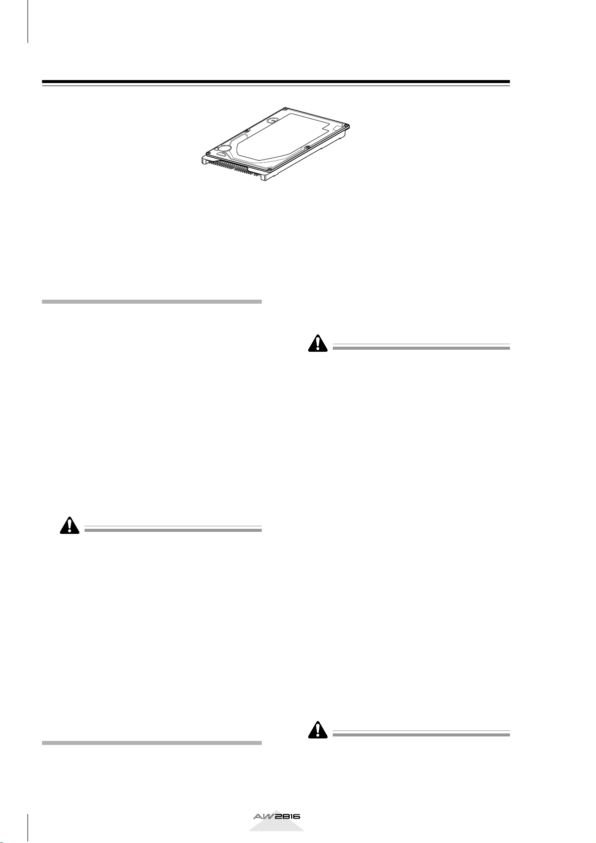
About the internal hard disk
On the AW2816, all data necessary for reproducing a
composition (mixer settings, recorder settings, audio
data etc.) is stored on the hard disk as a “song.”
An internal hard disk is installed by attaching it to the
inside of the hard disk cover plate located on the bottom panel of the AW2816. Hard disks with the following specifications can be used.
• Type: IDE 2.5 inch (attachment location conforms to SFF-8201)
• Thickness: no particular limitation
• Capacity: no particular limitation (however, the
AW2816 can use a maximum capacity of 64 GB)
• Models known to work: consult your local
Yamaha distributor or refer to the website at the
following URL.
<http://www.aw2816.com/>
• By “models known to work,” we mean commercially
available models that Yamaha has obtained, installed
in the AW2816, and successfully tested by means of
various operational tests. However, we cannot take
into account slight differences in performance that
may occur due to the manufacturing tolerances of
each manufacturer.
• Hard disks are precision devices. Strong physical
shock, magnetism, static electricity, or excessive current etc. can damage the data on a hard disk. You
must use media such as an external SCSI device or
CD-RW to backup your important musical data.
• Please be aware that Yamaha Corporation will
accept no responsibility for any damages, neither
direct nor indirect, resulting from the use of any of
the above hard disks.
The following steps describe the procedure by which
the 2.5 inch IDE hard disk is attached to the hard disk
cover plate located on the bottom of the AW2816 for
installation.
• Hard disks are precision devices. Do not subject
them to physical shock or static electricity, etc.
• Do not place a hard disk nearby devices that produce a strong magnetic field, or in locations of
extreme cold, heat, or moisture.
• Before you handle a hard disk, touch your hand to a
grounded metallic object to release any static
charge that may be present in your body or clothing.
If you fail to do so, static electricity may damage the
hard disk.
• Never attempt to disassemble a hard disk or apply
excessive force to it.
• In order to install the internal hard disk, you will
need to turn the AW2816 upside down. Please make
sure that your work surface is spacious enough.
• The AW2816 is shipped with four screws for attaching a 2.5 inch hard disk, and four screws for attaching a CD-RW drive, making a total of eight included
screws of the same type.
You will need the following items.
1
• The AW2816 itself
• A 2.5 inch IDE hard disk (sold separately) for
installation
• Four screws included with the AW2816 for
attaching the 2.5 inch hard disk
• A philips (+) screwdriver
• Work surface
Make sure that the power of the AW2816
2
is turned off. For safety’s sake, disconnect
the power cable from the AC outlet.
Installation
Please read and observe the cautions on installing
optional equipment listed at the beginning of this
manual.
2
Always switch off the power for the main unit and all
peripherals, unplug the power cord for the main unit
from the outlet, then disconnect the cables connecting the main unit with the peripherals before starting
installation work.
Operation section
Page 12
Spread a soft cloth over your work surface,
3
and place magazines or books to support
the four corners of the AW2816 so that the
faders, keys, and other controllers on the
top panel will not be damaged. Then turn
the AW2816 face down.
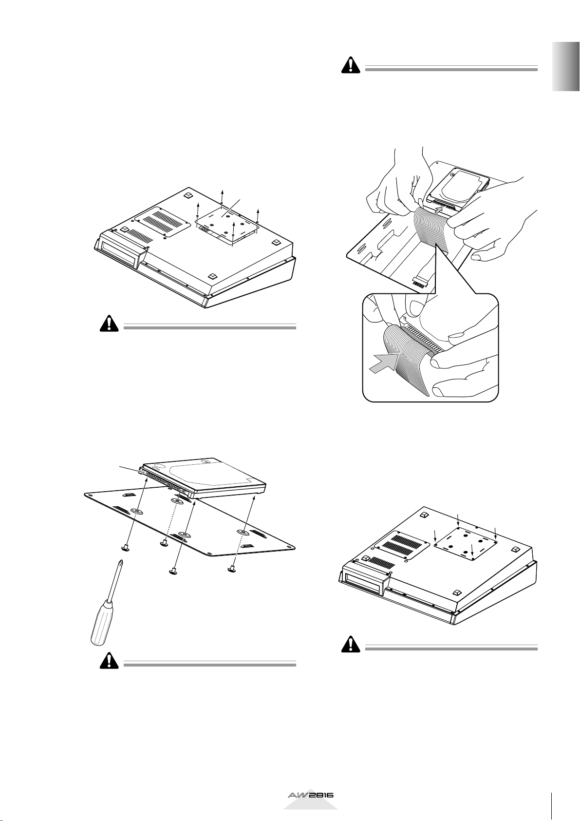
From the bottom, unfasten the hard disk
4
cover plate to which the internal 2.5 inch
IDE hard disk will be attached.
Hard disk
cover plate
The screws you remove will be used again to fasten
the cover plate, so be careful not to lose them.
• Even if the connector is difficult to insert, do not
attempt to insert it by applying excessive force.
Doing so may damage the hard disk, or you may
injure yourself.
• When inserting the connector, be careful that it is
not mis-aligned up/down or left/right.
Before you begin
Turn over the hard disk cover plate. As
5
shown in the illustration, place the hard
disk to be installed on the cover plate,
align the screw holes of the hard disk with
the holes of the cover panel, and use a
screwdriver and the included screws to fasten the hard disk at four locations.
Connector
As shown in the illustration place the cover
7
plate with the attached hard disk back
onto the bottom panel of the AW2816,
and fasten the cover plate to the bottom
panel using the four screws that you
removed in step 4.
If you fail to tighten the screws all the way, the hard
disk may vibrate and fail to operate correctly.
Pull out the flat cable from inside the
6
AW2816, and plug the flat cable into the
connector of the hard disk as shown in the
illustration. Press both ends of the flat
cable connector to ensure that it is firmly
plugged in all the way.
Operation section
• You must use the same screws that you removed in
step 4, or identical screws. Using longer screws may
damage the interior of the unit, or may cause electrical shock.
• Do not turn on the power of the AW2816 until all
options have been installed.
• When you turn on the power of the AW2816 after
installing a new hard disk, formatting of the hard
→
disk will begin automatically (
P.11).
3
Page 13
Before you begin
Installing a CD-RW drive
About the CD-RW drives
A CD-RW drive is an option that allows you to create
music CD’s, to backup/restore internal hard disk data,
to play a music CD or to read a CD-ROM. An internal-type CD-RW drive can be installed by removing
the CD-RW drive cover from the front panel. CD-RW
drives with the following specifications can be used.
• Interface: ATAPI
• Models known to work: consult your local
Yamaha distributor or refer to the website at the
following URL.
<http://www.aw2816.com/>
• CD-RW drives designed for internal installation can
be installed in the AW2816. Please be aware that
internal CD-RW drives designed for use with the
AW4416 cannot be used in the AW2816.
In the case of external SCSI-connected CD-RW
drives, a CD-RW drive usable with the AW4416 can
also be used with the AW2816.
• By “models known to work,” we mean commercially
available models that Yamaha has obtained, installed
in the AW2816, and successfully tested by means of
various operational tests. However, we cannot take
into account slight differences in performance that
may occur due to the manufacturing tolerances of
each manufacturer.
• Please be aware that Yamaha Corporation will
accept no responsibility for any damages, neither
direct nor indirect, resulting from the use of any of
the above CD-RW drives.
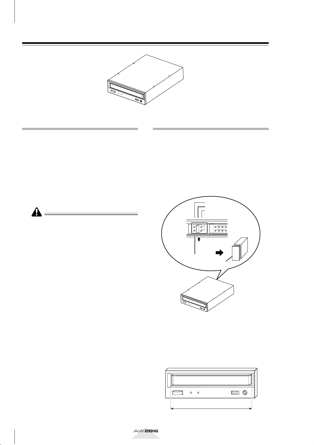
CD-RW drive settings
Insert the jumper (included with the CD-RW drive)
into the jumper switch on the rear panel of the CDRW drive to set your CD-RW drive to function as a
SLAVE unit. The AW2816 will not start up if the CDRW is set to a mode other than SLAVE.
• If you are installing a CD-RW drive manufactured by Yamaha, it will be set to SLAVE when
shipped from the factory, so you do not need to
change the setting.
CSEL
SLAVE
MASTER
Set to SLAVE
Jumper switch
Jumper
For details on this setting, refer to the manual that
came with your CD-RW drive.
4
* Note that the cover panel of the AW2816 cannot be
attached to a CD-RW drive with a lid-type tray. The
AW2816’s cover panel can be attached to a CD-RW
drive with a tray of the following dimensions.
Maximum 138 mm
Operation section
Page 14
Installation procedure
Power supply
connector
Flat cable
Please carefully read the cautions for installing
optional equipment given at the beginning of this
manual.
You will need the following items.
1
• The AW2816 itself
• Internal CD-RW drive (option)
• Four screws (included with the AW2816) for
attaching the CD-RW drive
• Philips (+) screwdriver
• Work surface
• In order to install the CD-RW drive you will need to
turn the AW2816 on its back. Make sure that you
have a sufficiently broad work surface.
• The AW2816 is shipped with four screws for attaching the 2.5 inch hard disk, and four screws for
attaching the CD-RW drive, making a total of eight
screws of the same type.
Make sure that the power of the AW2816
2
is turned off. For safety’s sake, disconnect
the power cable from the AC outlet.
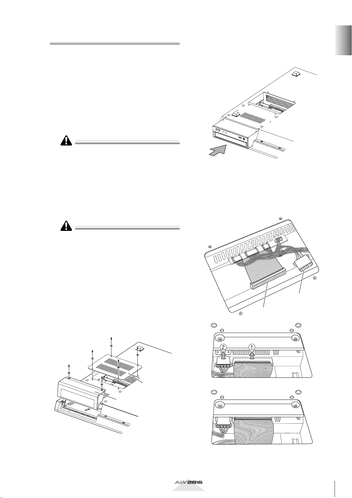
Turn the CD-RW drive over, and insert it lit-
5
tle by little, stopping when the connector
end of the CD-RW drive enters the opening
in the bottom of the AW2816.
Connect the flat cable (1) and CD-RW
6
drive power supply connector (2) (from
inside the AW2816) to the connectors of
the CD-RW drive. Connect the flat cable
first, and then the power supply connector.
Before you begin
Always switch off the power for the main unit and all
peripherals, unplug the power cord for the main unit
from the outlet, then disconnect the cables connecting the main unit with the peripherals before starting
installation work.
Spread a soft cloth over your work surface,
3
and place magazines or books to support
the four corners of the AW2816 so that the
faders, keys, and other controllers on the
top panel will not be damaged. Then turn
the AW2816 face down.
Remove the CD-RW drive cover from the
4
front panel, and remove the bottom panel.
Bottom panel
CD-R/RW drive
cover panel
Operation section
5
Page 15
Before you begin
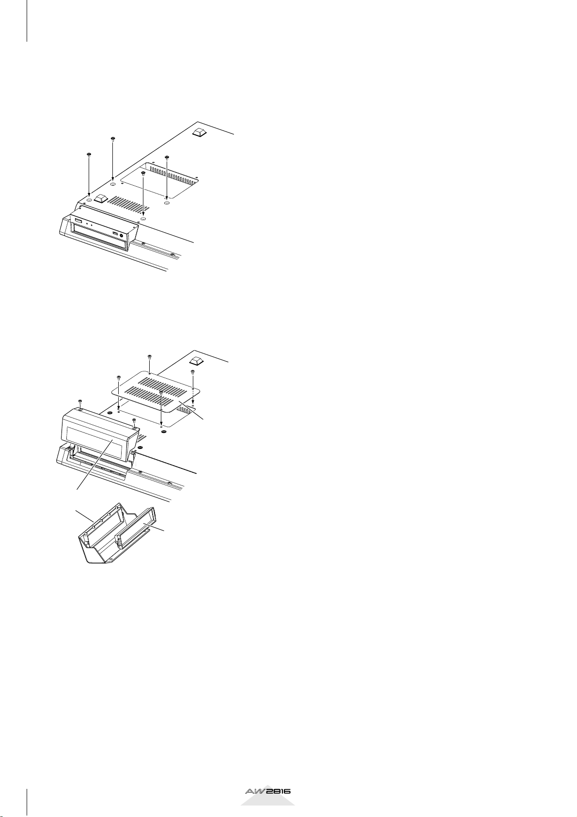
Align the fastening screw-holes on the bot-
7
tom of the CD-RW drive with the screwholes in the AW2816, and using a screwdriver and the included screws, fasten it in
four locations.
Re-attach the CD-RW drive cover and the
8
bottom panel that you removed in step 4.
At this time, remove the inner cover from
the CD-RW drive cover.
CD-R/RW drive
cover panel
Bottom panel
Inner cover
6
Operation section
Page 16
Removing the transport protection pad
The disc tray of some CD-RW drive models contains a
transport protection pad that protects the internal
mechanism from physical shock suffered during shipment. If your CD-RW drive contains this protective
pad, please remove it before use.
Be sure to save the transport protection pad for the
next time you need to transport the unit.
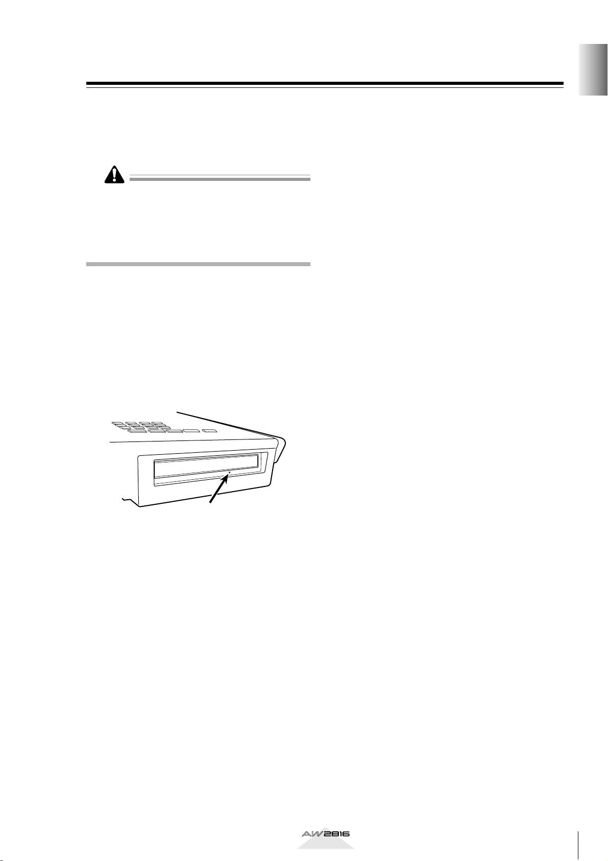
Manual eject (emergency disc
removal)
Manual eject allows you to remove the disc manually
in the case of an emergency such as a malfunction of
the disc tray mechanism (usually temporary) or a
power failure. Please be aware that using this method
frequently can cause the CD-RW drive to malfunction. For the location of the eject hole and the procedure, refer to the manual of your CD-RW drive.
In order to perform this operation, you will need a
pin-like object 2 mm or less in diameter, such as a
straightened paper clip.
Before you begin
Eject Hall
Insert a pin-like object 2 mm
or less in diameter.
* This diagram shows a CD-RW drive manufac-
tured by Yamaha Corporation.
Operation section
7
Page 17
Before you begin
Attaching an external SCSI device
About external SCSI devices
The external SCSI devices referred to here are storage
devices used to backup/restore the internal data of the
AW2816, and can be connected to the SCSI connector on the rear panel of the AW2816. The following
types of storage device can be used.
• Type of drive: MO drives (128 MB, 230 MB,
540MB, 640 MB 1.3 GB), hard disk drives, CDRW drives
• Interface: SCSI-2
• Models known to work: consult your local
Yamaha distributor or refer to the website at the
following URL.
<http://www.aw2816.com/>
• By “models known to work,” we mean commercially
available models that Yamaha has obtained, connected to the AW2816, and successfully tested by
means of various operational tests. However, we
cannot take into account slight differences in performance that may occur due to the manufacturing tolerances of each manufacturer.
• Please be aware that Yamaha Corporation will
accept no responsibility for any damages, neither
direct nor indirect, resulting from the use of any of
the above storage devices.
It is not possible to directly record or play back audio
signals in realtime on an external storage device connected to the SCSI connector.
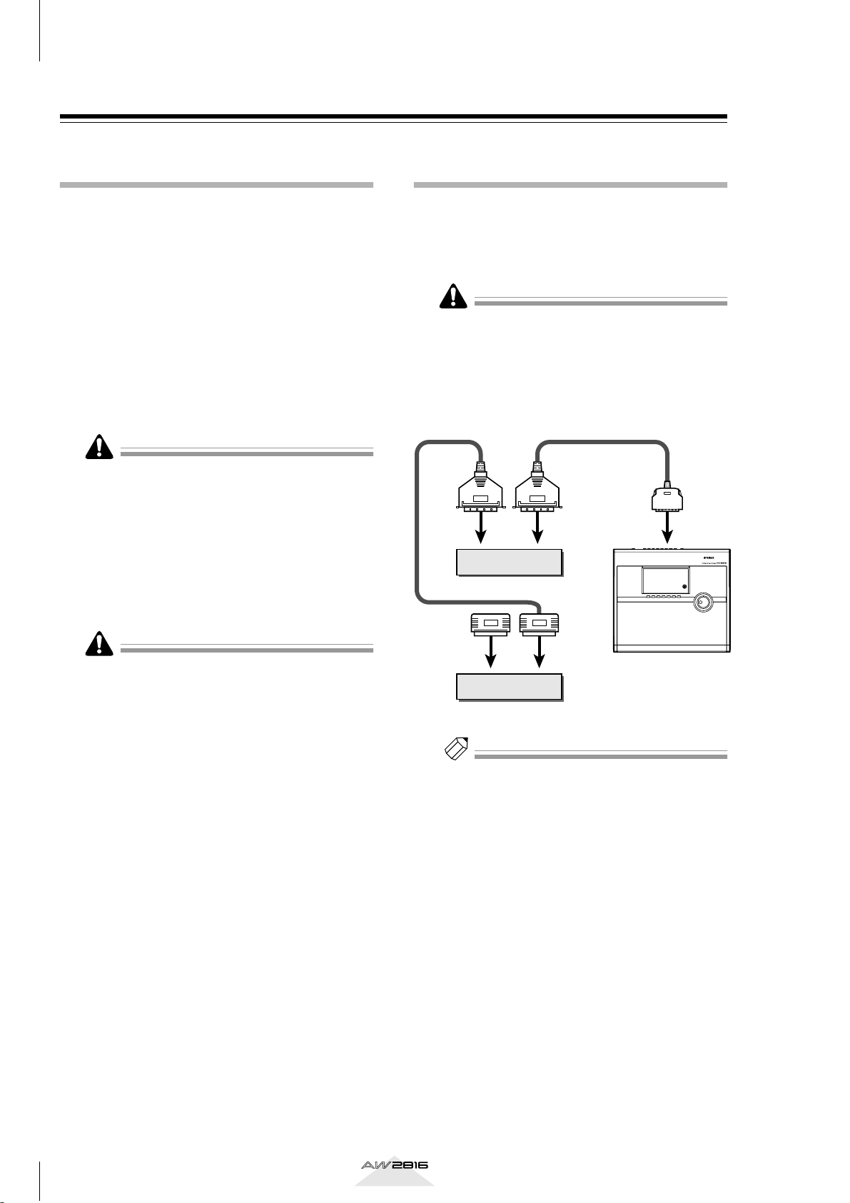
Connection procedure
Make sure that the power is turned off for
1
the AW2816 and for the external SCSI
device(s), and use a SCSI cable to connect
the SCSI connectors of each device.
Use only good-quality SCSI cables.
When connecting an external SCSI device, use
only high impedance SCSI cables of 100 ohms
(±10 ohms) impedance that are 1 meter or
shorter in length.
SCSI
connector
External SCSI device 1
Terminator
SCSI
connector
External SCSI device 2
SCSI
connector
AW2816
ID=6 (fixed)
SCSI
connector
SCSI
connector
Note
• A maximum of seven SCSI devices (SCSI ID= 0–5,7)
can be connected in a daisy-chain.
• When connecting multiple SCSI devices, you must
make sure that the SCSI ID of each device does not
conflict with any other device. (For details on how
to set the SCSI ID, refer to the manuals for your
SCSI devices.)
• The SCSI ID of the AW2816 itself is fixed at “6.”
8
Operation section
Page 18

Attach a terminator to the last SCSI device
2
in the chain.
A “terminator” is a device that terminates the
SCSI signal at the end of the chain, and is normally attached to the vacant SCSI connector of
the last device in the daisy chain. If the SCSI
device itself has a built-in terminator, turn it on.
(For details on how to turn on the internal terminator, refer to the manual of your SCSI device.)
Before using an external SCSI device, you will need to
format it. For details on this procedure, refer to
page 160.
■ About terminators
“Termination” refers to the process of applying a resistor appropriate for the impedance of the SCSI bus to
terminate the end of the circuit. The resistor required
for this is called the “terminator.” Normally, a terminator must be installed at the beginning and end of the
SCSI bus (in the case of the example in the previous
page, this would be the AW2816 itself, and the SCSI
device connected to the end of the daisy chain).
However, this is only a general principle, and is not
an absolute. Depending on the combination of SCSI
devices, the order of connection, or on the length of
the SCSI cables, there may be cases in which better
results are obtained by terminating only one end of
the chain. If problems occur such as the AW2816 failing to start up when an external SCSI device is connected, try defeating the terminator of the external
SCSI device. (The terminator inside the AW2816 is
always on, and cannot be defeated.)
●External SCSI devices with 25-pin connectors
Most SCSI cables with 25-pin connectors at both
ends do not meet SCSI specifications. For this reason if the system includes a SCSI device that uses a
25-pin connector, the problems may be due to this
type of cable.
●Daisy-chain connection
Sometimes the operation of a SCSI bus will be
unstable because of daisy-chain connections. Connect only the SCSI device you are using to the
AW2816.
●Power supply of SCSI devices
When using the system, turn on the power of all
connected SCSI devices. Operation of the SCSI bus
cannot be guaranteed if one of the connected
devices is not turned on.
Before you begin
■ About SCSI errors
The SCSI bus is able to transfer data in a stable manner only if all connected SCSI devices are operating
correctly. If the SCSI bus of the AW2816 is connected
to a device whose operation is unstable or which produces noise, errors may occur in other devices, or the
AW2816 may fail to start up correctly. If such problems occur, check the following points.
●Check the SCSI ID
Make sure that the SCSI ID of each SCSI device
(including the AW2816) does not conflict with the
SCSI ID of any other device. The SCSI ID of the
AW2816 is fixed at “6.”
●Check the terminator
Check the location of the terminator. Under certain
conditions, better results may be obtained by terminating only one end of the SCSI chain.
●Check the SCSI cables
Since errors are often caused by low-quality SCSI
cables or unnecessarily long SCSI cables, you
should avoid using such cables. Please use doubleshielded cables that are as short as possible. It is
also important that the shield within the cable is
grounded to the connector.
Operation section
9
Page 19
Before you begin
Installing I/O card
About I/O cards
I/O cards compatible with the Yamaha mini-YGDAI
format can be installed in the OPTION I/O slot
located on the rear panel of the AW2816 in order to
add input/output ports. For example by installing an
ADAT format compatible I/O card into an OPTION I/
O slot, you can transmit/receive eight channels of digital audio to/from an ADAT format digital recorder.
At present, the following types of I/O cards can be
used.
●MY8-AT
This card transmits and receives eight channels of
Alesis ADAT format digital signals.
●MY8-TD
This card transmits and receives eight channels of
TASCAM format digital signals.
●MY8-AE
This card transmits and receives eight channels of
AES/EBU format digital signals.
●MY8-AD
This is an A/D card with eight channels of analog
input jacks (balanced TRS phone jacks).
●MY4-AD
This is an A/D card with four channels of analog
input jacks (balanced XLR jacks).
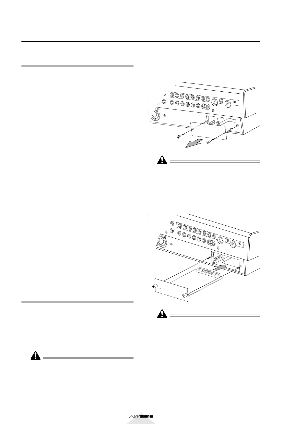
From the OPTION I/O slot located on the
2
rear panel of the AW2816, remove the two
screws that hold the cover in place.
Please keep the cover and screws you removed in a
safe place.
Slide the I/O card along the rails inside the
3
slot until it clicks into place.
Tighten the two screws included with the
4
I/O card to fasten the card securely.
●MY4-DA
This is a D/A card with four channels of analog output jacks (balanced XLR jacks).
For up-to-date information on available MY cards,
contact your local Yamaha distributor or check the following website.
<http://www.aw2816.com/>
Installation procedure
Please carefully read the cautions for installing
optional devices, given at the beginning of this manual.
Make sure that the power of the AW2816
1
is turned off. For safety’s sake, disconnect
the power cable from the AC outlet.
Always switch off the power for the main unit and all
peripherals, unplug the power cord for the main unit
from the outlet, then disconnect the cables connecting the main unit with the peripherals before starting
installation work.
Please note that if the screws are loose, the card may
not be grounded correctly.
10
Operation section
Page 20
Please observe the following points
This section explains how to turn the power of the AW2816 on and off, and how to set
the internal clock.
Turning the power on
When turning on the power of a system that includes
the AW2816, each device must be turned on in the
following order.
1 Any storage devices connected to the SCSI
connector of the AW2816, and external tone
generators connected to the input/output
jacks
B The AW2816 itself
C The monitor system connected to the output
jacks or the AW2816
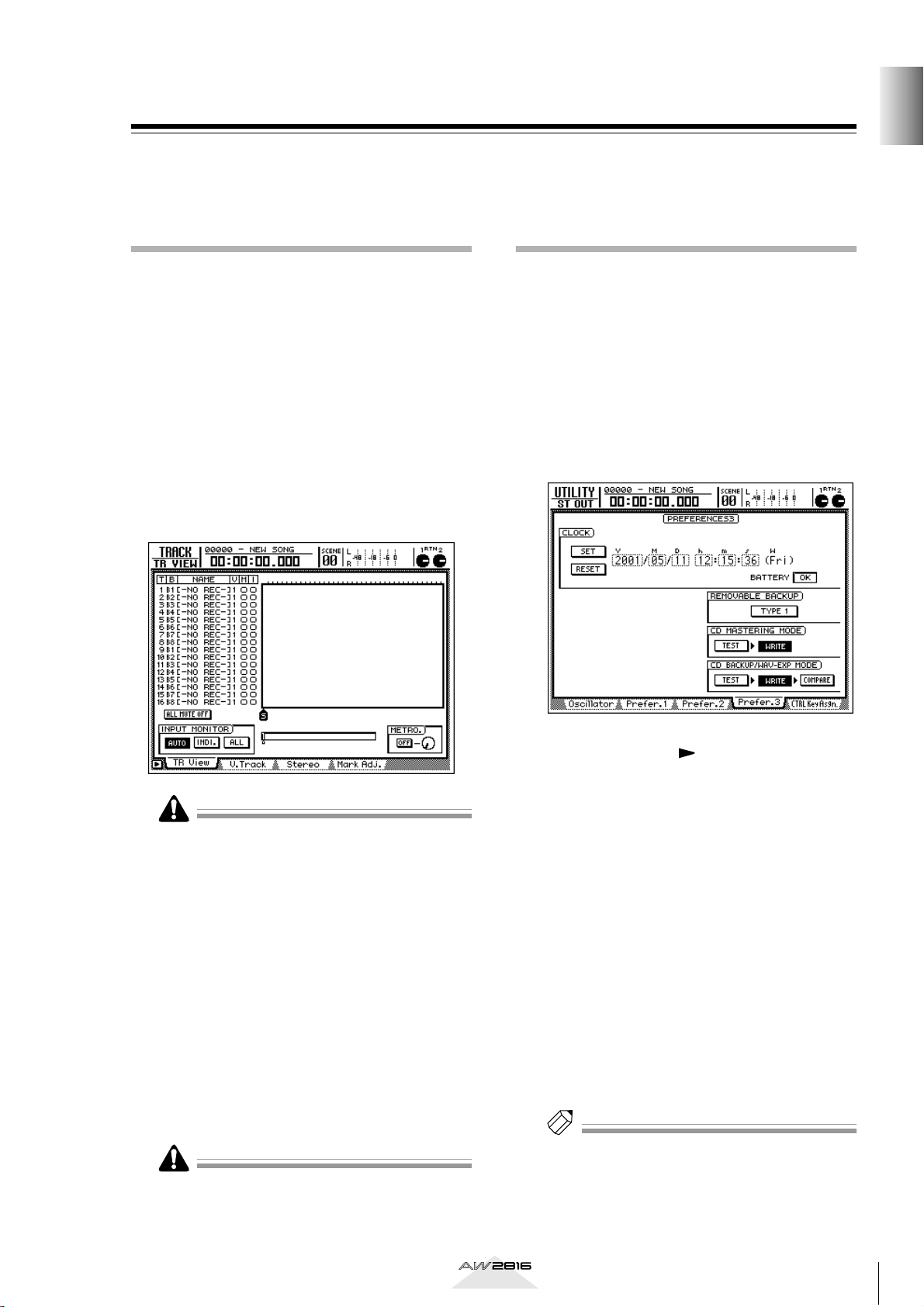
Following the opening screen, the following screen
will appear in the display of the AW2816.
Setting the internal clock
When the AW2816 is shipped from the factory, the
internal clock is set to Japan time. When you save a
song you created on the AW2816, the date and time
will be stored according to this internal clock.
Use the following procedure to set the date and time
of the internal clock after replacing the internal battery, or if you need to set the clock for any other reason.
Press the [UTILITY] key → [F4] key.
1
The following screen will appear.
Before you begin
• If the AW2816 is powered-on when a SCSI-connected external device is turned off, it may not start
up correctly.
• Do not turn off the power of a SCSI-connected
device while the AW2816 is in use.
• Before turning the power on, check that the power
cable plug is firmly connected to the AW2816 and to
the AC outlet. If the power is accidentally disconnected (turned off) while the AW2816 is in use, the
AW2816 itself and/or the hard disk may be damaged.
The first time the power is turned on after a new internal hard disk is installed in the AW2816, the display
will indicate “Format OK? [Y (Enter)/N (Any)].” If you
press the [ENTER] key at this time, the hard disk will
be formatted automatically, and the screen shown
above will appear when formatting has been completed.
Never turn off the power of the AW2816 while formatting is in progress. Doing so may damage the hard
disk itself.
Use the CURSOR [ ] key to move the cur-
2
sor (the blinking area in the display) to the
Y (year) field in the CLOCK area, and turn
the [DATA/JOG] dial to set the year.
The clock field will begin blinking.
In the same way, input the M (month), D
3
(date), h (hour), m (minute), and s (second) fields.
The W (weekday) field will be set automatically
according to the date.
When you have input all of the values, use
4
the CURSOR keys to move the cursor to
the SET button, and press the [ENTER] key.
The CLOCK area will stop blinking, and the new
date and time will take effect. If you decide not
to change the date and time, move the cursor to
the RESET button and press the [ENTER] key.
Tip!
The internal clock continues to operate even when the
power of the AW2816 is turned off. Once you have
set the clock, you will not need to reset it unless you
change the battery.
Operation section
11
Page 21

Before you begin
Turning the power off
When turning off the power of a system that includes
the AW2816, each device must be turned off in the
following order.
1 The monitor system connected to the output
jacks or the AW2816
B The AW2816 itself
C Any storage devices connected to the SCSI
connector of the AW2816, and external tone
generators connected to the input/output
jacks
When turning off the power of the AW2816 itself, you
must use the shutdown procedure described below.
In the WORK NAVIGATE section located on
1
the top panel of the AW2816, press the
[SONG] key.
Press the [F5] (SHUT DOWN) key located
2
below the display.
Press the [ENTER] key.
3
A message will ask you whether you want to save
the current song.
Use the CURSOR keys located in the right
4
center of the top panel to move the cursor
to the OK button, and press the [ENTER]
key.
When a message of “Now safe to turn off”
5
appears, turn off the [POWER] switch of
the rear panel.
• If you turn off the power of the AW2816 without
using the above shutdown procedure, the data on
the hard disk may be damaged.
• Never turn off the power while the access indicator
which indicates the access status of the internal hard
disk is lit. Doing so may damage the hard disk itself.
12
Operation section
Page 22
Chapter
234
1
1
Analog input/output section
Parts and their functions
This chapter explains the functions of each part of the AW2816’s top
panel, rear panel, and front panel.
1
Parts and their functions
The names of controllers (keys and knobs etc.) on the top panel are enclosed in square brackets
[ ] in order to distinguish them from the software knobs and buttons that appear in the display.
Example: [SEL] key, [GAIN] control
Top panel
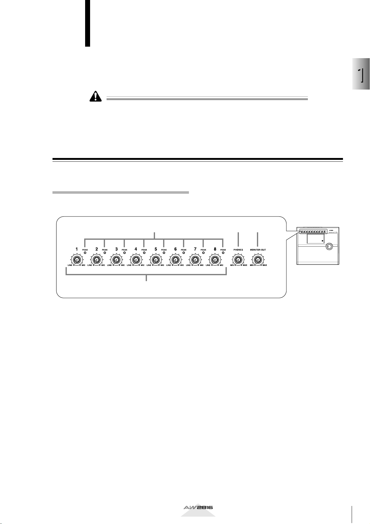
A [GAIN] control
These knobs adjust the input sensitivity of INPUT
jacks 1–8 over a range of +4 dB to –46 dB. They
support signals ranging from line level devices
such as synthesizers to mic inputs.
B [PEAK] indicators
A [PEAK] indicator will light red if the input signal
that has passed through the [GAIN] control
reaches a level 3 dB below the clipping point. In
order to record at the optimal level, adjust the
[GAIN] control (1) so that this indicator flickers
briefly when you play most loudly.
C [PHONES] (headphones) control
This knob adjusts the volume of the headphones
connected to the rear panel PHONES jack.
D [MONITOR OUT] control
This knob adjusts the level of the signal that is output from the rear panel MONITOR OUT jacks.
Operation section
13
Page 23
Chapter
Parts and their functions
1
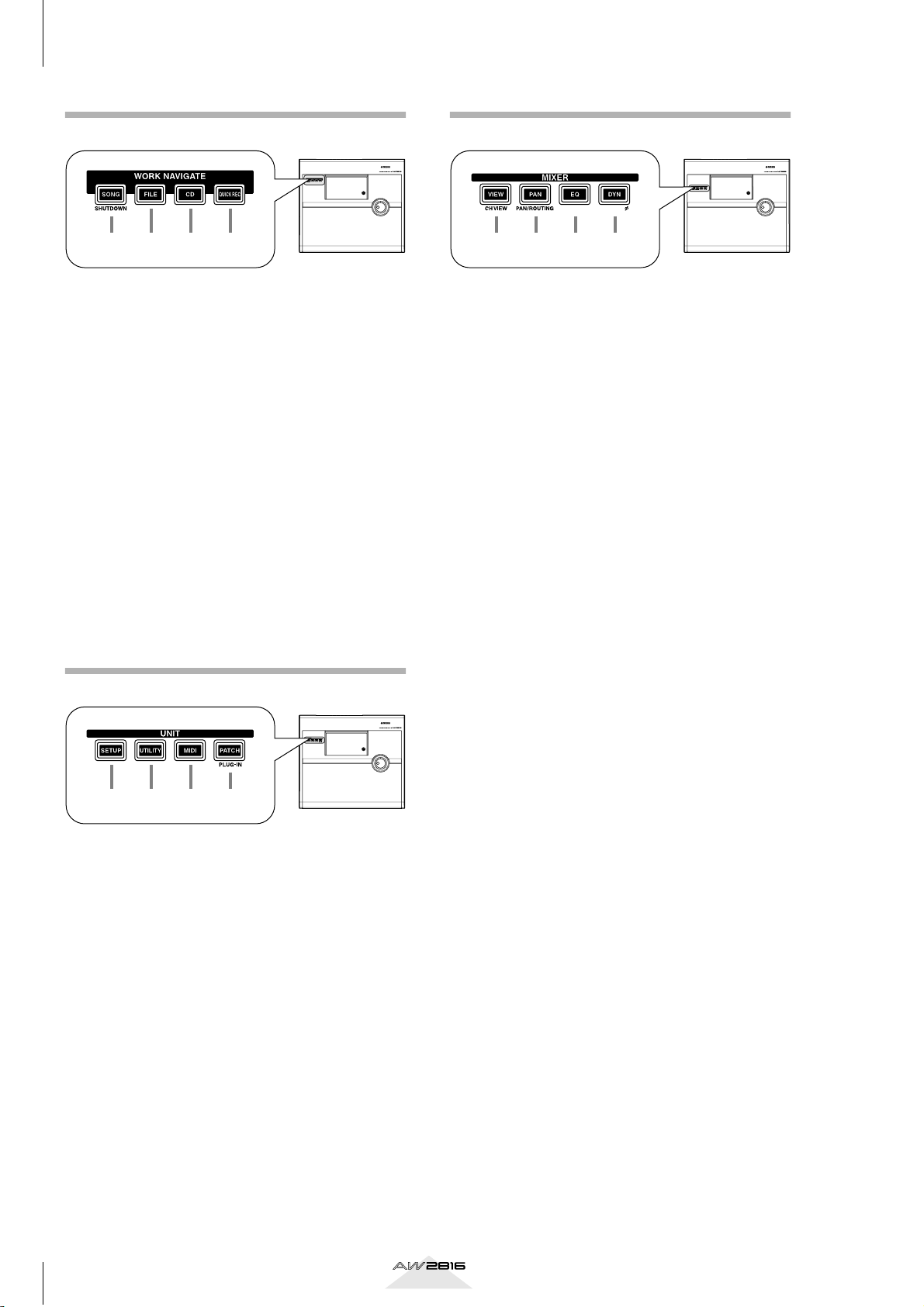
WORK NAVIGATE section
MIXER section
EQ/ATT/GRP
DYN/DLY/
EQ/ATT/GRP
DYN/DLY/
1 2 3 4
A [SONG] key
This key accesses the SONG screen, where you
can save or load songs, or shut down the AW2816.
B [FILE] key
This key accesses the FILE screen, where you can
backup and restore songs, and format or erase an
internal/external drive.
C [CD] key
This key accesses the CD screen, where you can
use an optional CD-RW drive to create an audio
CD, or play back an audio CD.
D [QUICK REC] (Quick Record) key
This key accesses the QUICK REC screen, where
you can instantly patch input signals to tracks.
UNIT section
1 2 3 4
A [VIEW] key
This key accesses the VIEW screen, where you can
view all mix parameters for a specified channel.
B [PAN] key
This key accesses the PAN/ROUTE screen, where
you can set pan and routing for each channel.
C EQ (Equalizer) key
This key accesses the EQ/ATT/GRP screen, where
you can set the EQ and attenuator of each channel, and make fader group and mute group settings.
D [DYN] (Dynamics) key
This key accesses the DYN/DLY screen, where you
can make dynamics processor settings for a
selected channel, and set the delay and phase of
each channel.
1 2 3 4
A [SETUP] key
This key accesses the SETUP screen, where you
can make basic settings for the AW2816 such as
word clock, dither, and solo.
B [UTILITY] key
This key accesses the UTILITY screen, where you
can operate the test tone oscillator, and make settings for the operating environment of the
AW2816.
C [MID] key
This key accesses the MIDI screen, where you can
make MIDI-related settings.
D [PATCH] key
This key accesses the PATCH screen, where you
can patch external inputs/outputs to internal signal
routes.
14
Operation section
Page 24
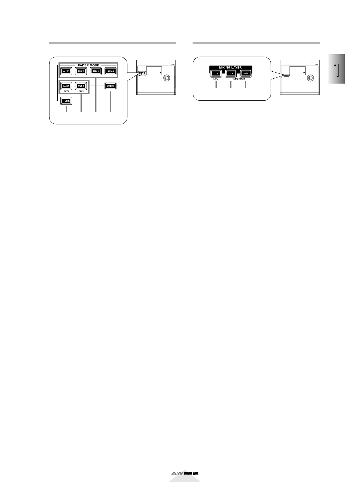
FADER MODE section
MIXING LAYER section
1
Parts and their functions
1 2 3
1234
This section selects the parameters that will be controlled by the top panel faders 1–8. The selected key
will light.
A [HOME] key
When this key is on, you can use faders 1–8 to
control the input levels of the channels currently
selected in the MIXING LAYER section. The display will show the HOME screen, where you can
view meters that indicate the input/output levels of
each channel.
B [AUX 5]/[AUX 6] keys
When these keys are on, you can use faders 1–8 to
adjust the send levels of the signals sent to internal
effects 1/2 from the channels currently selected in
the MIXING LAYER section. The display will show
the AUX5/EFF1 screen or AUX6/EFF2 screen,
where you can make on/off and pre/post settings
for the signals sent from each channel to internal
effects 1/2, and set effect parameters.
A INPUT [1-8] key
B RECORDER [1-8] key
C RECORDER [9-16] key
These keys select the channels (mixing layer) that
will be operated by [SEL] keys 1–8, [ON] keys 1–
8, and faders 1–8.
The currently selected key will light. When the
respective key is selected, the [SEL] keys 1–8,
[ON] keys 1–8, and faders 1–8 will operate the
mixing layers listed below.
● When the INPUT [1-8] key is lit
Input channels 1–8
● When the RECORDER [1-8] key is lit
Monitor channels 1–8
●When the RECORDER [9-16] key is lit
Monitor channels 9–16
For details on channels and mixing layers, refer to
page 38.
C [AUX 1]–[AUX 4] keys
When this key is on, you can use faders 1–8 to
control the send levels of the signals sent to AUX
buses 1–4 from the channels selected in the MIXING LAYER section. The display will show the
AUX 1–AUX 4 screens, where you can make on/
off and pre/post settings for the signals sent from
each channel to AUX 1–4.
D [REMOTE] key
When this key is on, you can use faders 1–8 and
[ON] keys 1–8 to remotely control external MIDI
devices. The display will show the REMOTE
screen, where you can make settings related to
remote control.
Operation section
15
Page 25
Chapter
Parts and their functions
1
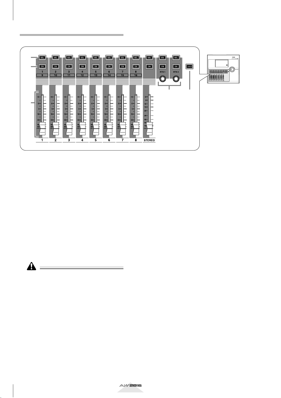
Fader section
1
2
3
54
A [SEL] keys (1–8/STEREO/RTN 1/RTN 2)
These keys select the channel for operation.
B [ON] keys (1–8/STEREO/RTN 1/RTN 2)
These keys turn each channel on/off.
C Faders (1–8/STEREO)
According to the settings of the FADER MODE
section and MIXING LAYER section, these moving
faders adjust either the input level of each channel
or the send level of each channel to AUX buses 1–
6.
D [RTN 1]/[RTN 2] controls
According to the settings of the FADER MODE
section, these knobs adjust either the level of
return channels 1/2 (effect return) or the send level
from return channels 1/2 to AUX buses 1–6.
Return channel 1 does not have a send level to AUX
bus 5. Similarly, return channel 2 does not have a send
level to AUX bus 6.
E [SOLO] key (1–16/STEREO/RTN 1/RTN 2)
This key switches the Solo function on/off.
16
Operation section
Page 26
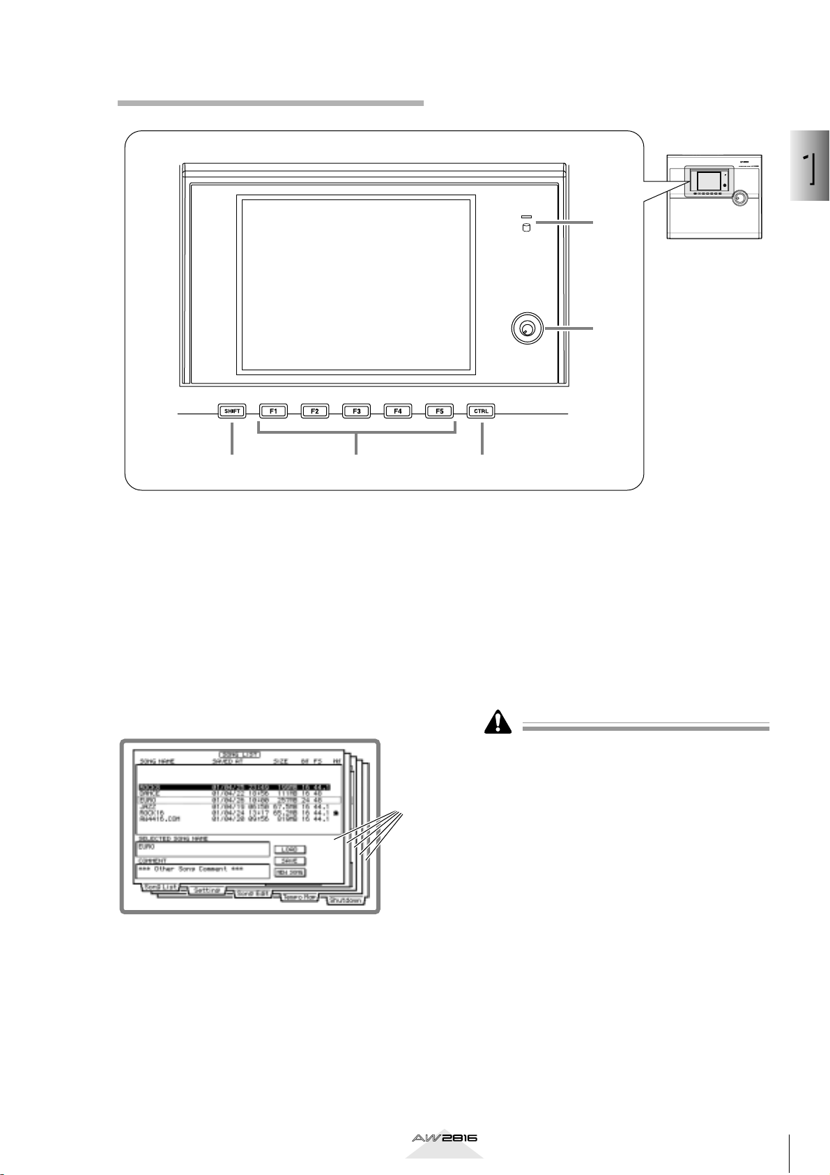
Display section
1
Parts and their functions
6
1
5
42 3
A Display
This is a 320 x 240 pixel liquid crystal display with
backlight, that displays the mix parameter settings
and the current operating status.
When you press one of the keys in the WORK
NAVIGATE or UNIT section, the screen for the
corresponding key will appear. Most screens consist of multiple “pages” (the name of the pages in
each screen are indicated by tabs at the bottom of
the screen), and you can use the [F1]–[F5] keys
(3) to access the desired page.
Screen
pages
D [CTRL] (Control) key
This key is used in conjunction with the function
keys (3) to execute user-defined functions.
E Contrast
This knob adjusts the brightness of the display.
F Access indicator
This indicator indicates the access status of the
internal hard disk. When the hard disk is being
read or written, this indicator will light.
Never turn off the power of the AW2816 when the
access indicator is lit. Doing so will not only damage
the data on the internal hard disk, but may also damage the hard disk itself. When you want to turn off the
power of the AW2816, you must perform the shut-
→
down procedure (
P.12).
B [SHIFT] key
This key is used in conjunction with the function
keys (3) to execute additional functions.
C [F1]–[F5] (Function 1–5) keys
These keys select pages within the currently
selected screen. When the [SHIFT] key or [CTRL]
key is held down, these keys execute additional
functions assigned to each key.
Operation section
17
Page 27
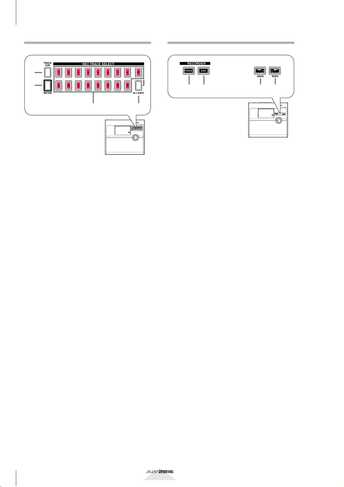
Chapter
Parts and their functions
1
REC TRACK SELECT section
1
RECORDER section
2
3
A [CUE] key
This key allows the output of tracks 1–16 or the
stereo track to be monitored directly from the
MONITOR OUT jacks without passing through
the monitor channel.
Use the REC TRACK SELECT keys (3) to select a
track. When you press the [CUE] key, the [CUE]
key and the REC TRACK SELECT keys will blink,
allowing you to select a track. Press a REC TRACK
SELECT key to select a track, and that key will
light.
B [METER] key
This key accesses the METER screen, where you
can view meters of the input/output level of tracks
1–16 and the output level of the stereo output
channel.
1 2 3 4
4
A [TRACK] key
This key accesses the TRACK screen, where you
can operate the audio tracks of the recorder section.
B [EDIT] key
This key accesses the EDIT screen, where you can
edit the audio tracks that have been recorded.
C [UNDO] key
This key cancels the most recently performed
recording or editing operation, returning to the
previous state (Undo). When the Undo function is
available, the [UNDO] key will light.
D [REDO] key
This key re-executes the recording or editing operation that was cancelled by the [UNDO] key
(Redo). When the Redo function is available, the
[REDO] key will light.
C REC TRACK SELECT [1]–[16]/[ST]
These keys select the recording track (tracks 1–16
or the stereo track).
D [ALL SAFE] key
This key cancels record-ready mode for all tracks.
If any tracks are muted, all muting will be cancelled.
18
Operation section
Page 28
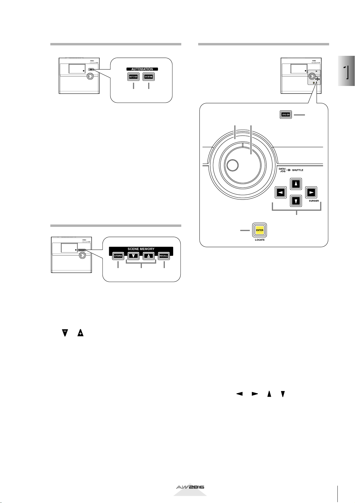
AUTOMATION section
CURSOR/JOG&SHUTTLE section
1
1 2
A [AUTOMIX] key
This key accesses the AUTOMIX screen, where
you can perform automix operations. By using
automix, operations of mix parameters such as the
faders and [ON] keys can be recorded in realtime.
B [SCENE] key
This key accesses the SCENE screen, where you
can perform scene memory operations. By using
scene memories, you can save the current state of
the mixer section and the input/output patching
state.
SCENE MEMORY section
Parts and their functions
1
23
4
5
1 3
2
A [STORE] key
This key saves the current state of the mixer section and input/output patching to the scene number shown in the display.
B [ ]/[ ] keys
These keys select the store destination or recall
source scene number.
C [RECALL] key
This key recalls the scene number currently shown
in the display.
A [JOG ON] key
This key is an on/off switch for the Nudge function
(a destination that repeatedly plays a specified
region before or after the current location) controlled by the [DATA/JOG], [SHUTTLE] dial. When
the Nudge function is on, the [JOG ON] key will
light.
B [DATA/JOG] dial
Depending on the on/off status of the [JOG ON]
key and the [NUM LOCATE] key of the Locate section, this dial is used to edit parameter values or to
operate the Nudge function.
C [SHUTTLE] dial
Depending on the on/off status of the [JOG ON]
key, this dial rewinds or fast-forwards the playback
(review or cue), or operates the Nudge function.
D CURSOR [ ]/[ ]/[ ]/[ ] keys
These keys are used to move the cursor (the blinking box) in the display.
E [ENTER] key
This key is used to operate a button displayed in
the screen, to finalize a numerical value that you
input, or to execute a specific function.
Operation section
19
Page 29
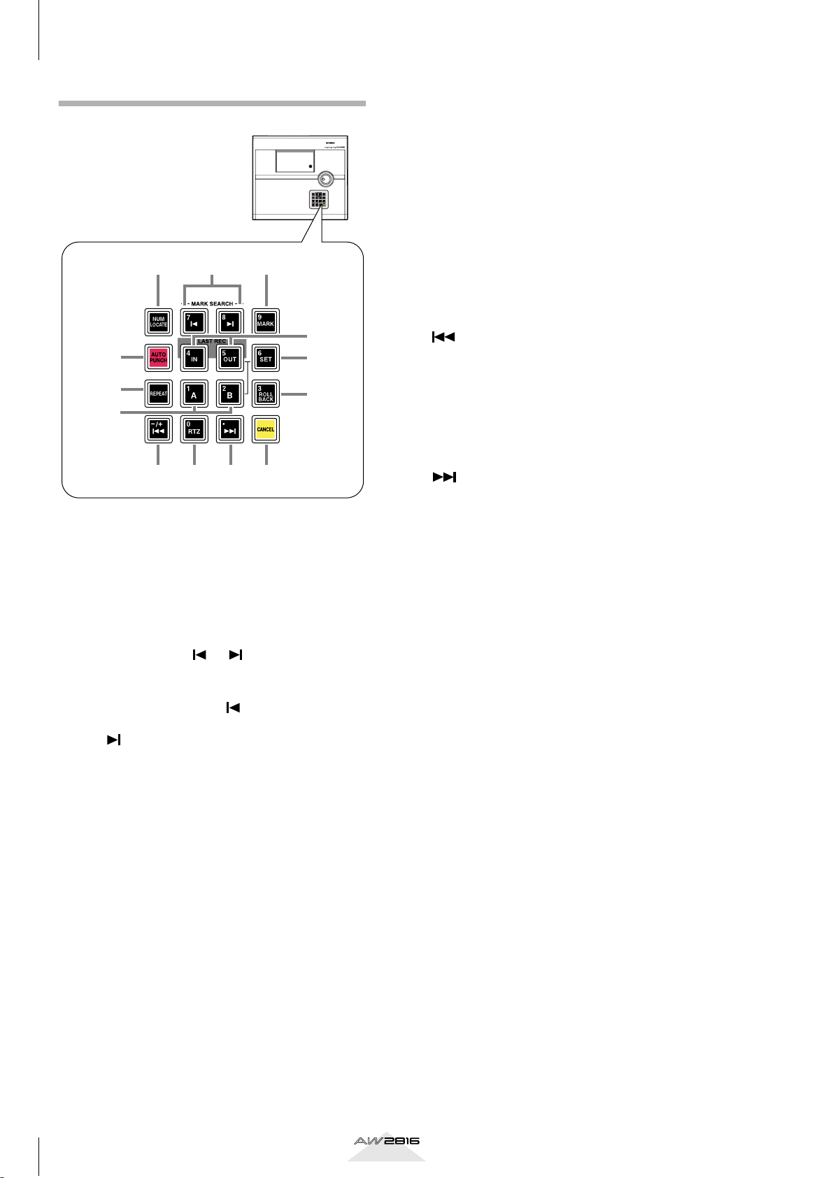
Chapter
Parts and their functions
1
LOCATE section
132
G [REPEAT] key
This key is an on/off switch for the A-B Repeat
function which repeatedly plays a specified
region.
H [A]/[B] keys
These keys set the beginning (A point) and end (B
point) of the region played by the A-B Repeat function. These keys can also be used as locate keys to
specify the A point or B point as locate destinations.
I [ROLL BACK] key
This key rewinds the current location by a specified distance.
5
4
7
6
9
8
JKLM
A [NUM LOCATE] key
This key is used to specify a location numerically.
When this key is lit, you can use the numeric keys
or the [DATA/JOG] dial to input a location, and
press the [ENTER] key to execute the locate operation.
B MARK SEARCH [ ]/[ ] keys
These keys are used to search for markers placed
in a song. If a marker has been placed earlier than
the current location, the [ ] key will light. If a
marker has been placed after the current location,
the [ ] key will light.
J [ ] key
This key locates to the absolute time zero location
(start point).
K [RTZ] (Return to zero) key
This key locates to the counter zero location
(when the counter is displaying measures, this will
be the beginning of the first measure).
L [ ] key
This key locates to the last location at which audio
is recorded (end point).
M [CANCEL] key
In conjunction with the LAST REC [IN]/[OUT]
keys, [A]/[B] keys, and [MARK] keys, this key
erases a locate point from the song.
C [MARK] key
This key sets a marker at the current location of the
song.
D [AUTO PUNCH] key
This key turns the auto punch-in/out function on/
off.
E LAST REC [IN/[OUT] (Last recording in/
out) key
These keys set the recording start location (In
point) and end location (Out point) for auto
punch-in/out. When these keys are lit, you can use
them as locate keys to move to the point at which
recording most recently began (In point) or ended
(Out point).
F [SET] key
This key is used in conjunction with the LAST REC
[IN]/[OUT] keys or the [A]/[B] keys to set the current location of the song to a locate point.
20
Operation section
Page 30
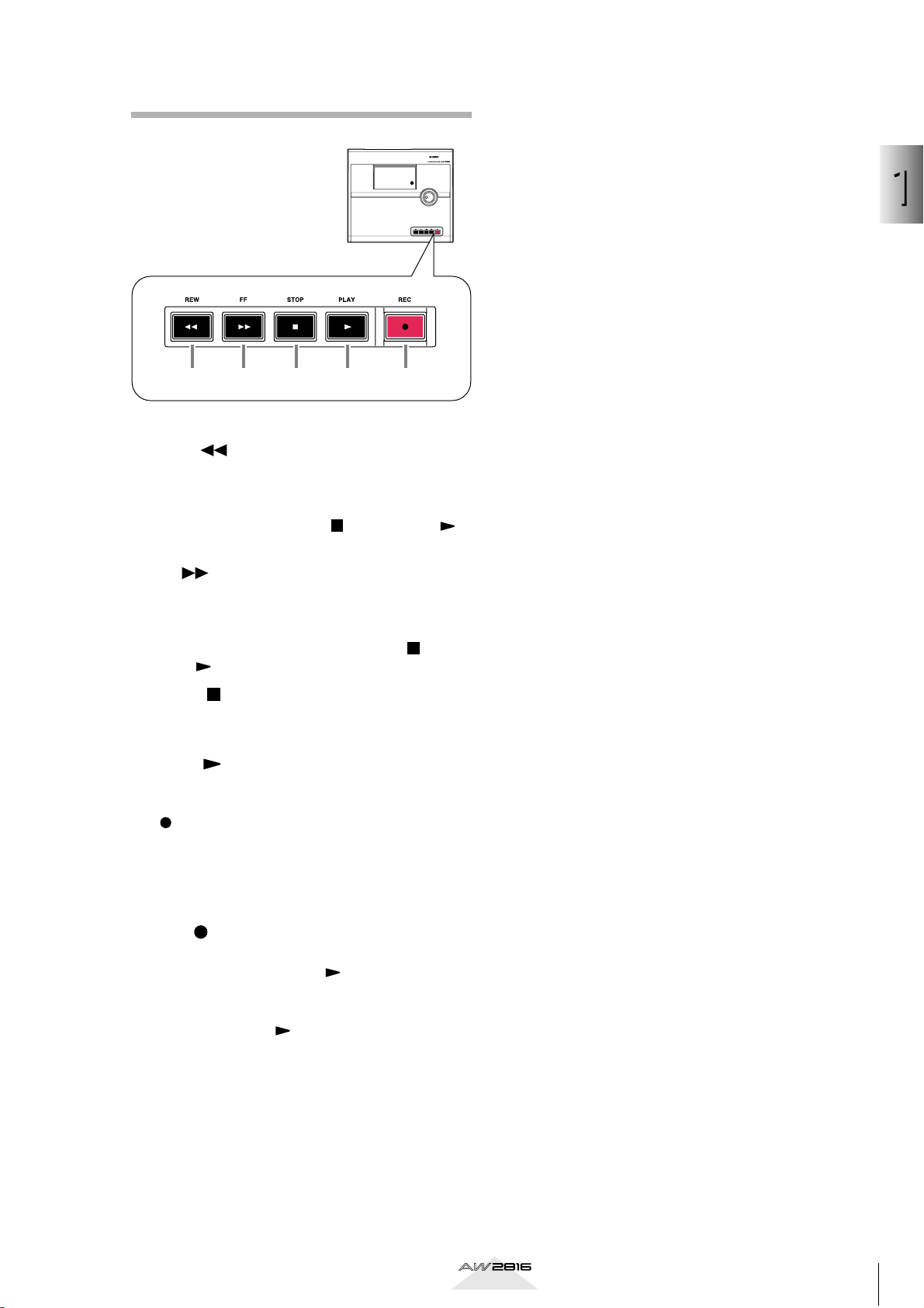
Transport section
1 2 3 4 5
A REW [ ] (Rewind) key
This key rewinds from the current location. Each
time you press this key, you will switch between
8X speed and 16X speed rewinding. To stop
rewinding, press the STOP [ ] key or PLAY [ ]
key.
1
Parts and their functions
B FF [ ] (Fast-forward) key
This key fast-forwards from the current location.
Each time you press this key, you will switch
between 8X speed and 16X speed fast-forwarding.
To stop fast-forwarding, press the STOP [ ] key or
PLAY [ ] key.
C STOP [ ] key
This key stops playback, recording, fast-forward,
or rewind.
D PLAY [ ] key
When the recorder is stopped, pressing this key
will begin playback. (If you hold down the REC
[ ] key and press this key, recording will begin.)
Pressing this key during rewind or fast-forward will
switch to normal-speed playback.
Pressing this key during recording will stop recording and continue pressing (i.e., punch-out).
E REC [ ] (Record) key
When the recorder is stopped, holding down this
key and pressing the PLAY[ ] key will begin
recording.
During playback, holding down this key and
pressing the PLAY [ ] key will switch from playback to recording (i.e., punch-in).
Operation section
21
Page 31

Chapter
Parts and their functions
1
Rear panel
A [PHANTOM +48V ON/OFF] switch
This switch supplies +48 V phantom power to the
INPUT (XLR) 1/2 jacks (2). Turn this switch ON
when condenser mics that require an external
power supply are connected to the INPUT 1/2
(XLR) jacks.
432
9OPQR786T SU
• If plugs are inserted into both the XLR jack and TRS
phone jack of INPUT 1/2, the TRS phone jack will
take priority.
• Phantom power is not supplied from the INPUT 1/2
(TRS phone) jack.
15JN M L K
• This switch must be turned off if devices not requiring an external power supply are connected to the
INPUT 1/2 (XLR) jacks.
• If the phantom power supply is turned on, power will
be supplied to both the INPUT (XLR) 1 and 2 jacks.
B INPUT 1/2 (XLR) jacks
These are XLR-3-31 type input jacks for connecting balanced condenser mics or line level devices.
The nominal input level is +4 dB to –46 dB. The
pin wiring is as follows.
Male XLR connector
1 (ground)
3 (cold)
2 (hot)
C INPUT 1/2 (TRS phone) jacks
These are balanced TRS phone input jacks.
Devices with unbalanced output, such as synthesizers, can also be connected. The nominal input
level is –46 dB – +4 dB. The pin wiring is as follows.
Tip (hot)
1/4" TRS phone plug
Ring (cold)
Sleeve (ground)
D INPUT 3–8 (TRS phone) jacks
These are balanced TRS phone input jacks. The
specifications of these jacks are the same as for the
INPUT 1/2 (phone) jacks.
E INPUT 8 (Hi-Z) jack
This is a high-impedance unbalanced phone input
jack. Instruments with a high output impedance
such as passive-type electric guitars can be connected directly to this jack. The nominal input
level is –46 dB to +4 dB.
If plugs are inserted into both the TRS phone jack and
the Hi-Z jack for INPUT 8, the Hi-Z jack will take priority.
F OPTION I/O slot
An optional I/O card can be installed in this slot.
Tip!
For details on installing an I/O card, refer to page 10.
G STEREO OUT jacks
These unbalanced RCA phono jacks are analog
outputs for the signal selected in the PATCH
screen Patch OUT page (→P.284). The nominal
output level is –10 dBV.
H MONITOR OUT jacks
These balanced TRS phone jacks are analog outputs for monitoring the stereo bus, internal metronome, solo signal, or direct output of recorder
tracks 1–16. The nominal output level is +4 dB.
22
Operation section
Page 32

I OMNI OUT jacks
These unbalanced phone jacks are analog outputs
for the signals selected in the PATCH screen Patch
OUT page (→P.284). The nominal output level is
0 dB.
J PHONES jack
A set of stereo headphones can be connected to
this jack. This jack will always output the same signal as the MONITOR OUT jacks.
K DIGITAL STEREO IN jack
This is a coaxial jack for digital input of a stereo
signal. It supports the IEC 958 consumer format.
L DIGITAL STEREO OUT jack
This is a coaxial jack for digital output of the signal
selected in the PATCH screen Patch OUT page
(→P.284). It supports the IEC 958 consumer for-
mat.
M SCSI connector
This is a D-sub half-pitch 50 pin SCSI connector
compatible with the SCSI-2 specification. External
SCSI-2 devices such as CD-RW drives or MOD
drives can be connected here.
The MTC OUT connector is dedicated to transmitting MTC (MIDI Time Code).
S POWER switch
This switch turns the power on/off.
To turn the power on/off, you must use the procedures described in “Turning the power on” and
“Turning the power off,” pages 11–12.
T AC INLET connector
The included power cable is inserted into this connector to supply power. Use only the included
cable.
U Grounding terminal
This terminal is used when grounding the chassis
of the AW2816. To prevent electrical shock, you
must make this connection before plugging the
power cable into the AC outlet. This connection
will also help prevent hum and other noise.
1
Parts and their functions
• To connect an external device, use only a high
impedance SCSI cable with impedance of 100 ohms
(±10 ohms) and a length of 1 meter or less.
• External devices connected to the SCSI connector are
used mainly to back up song data. It is not possible to
record a song using an external SCSI device instead
of the internal hard disk.
N TO HOST connector
This is an 8-pin mini-DIN connector that can be
connected directly to the serial port of a PC or
Macintosh for use with MIDI application programs.
O FOOT SW jack
An optional foot switch (Yamaha FC5) can be connected to this jack. You can use the foot switch to
perform transport operations such as playback/
stop, and to control manual punch-in/out.
Foot switches other than the Yamaha FC5 (or equivalent) may not operate correctly.
P MIDI IN connector
Q MIDI OUT/THRU connector
R MTC OUT connector
These connectors can be connected to external
MIDI devices to exchange MIDI messages.
The MIDI IN connector is for reception only.
The MIDI OUT/THRU connector can be switched
internally to function either as a MIDI OUT connector (to transmit the AW2816’s own MIDI messages) or as a MIDI THRU connector (to retransmit received messages without change).
Operation section
23
Page 33

Chapter
Parts and their functions
1
A CD-RW drive cover
This covers the installation bay for the optional
CD-RW drive.
Tip!
For details on installing a CD-RW drive, refer to
page 4.
Front panel
1
24
Operation section
Page 34

Chapter
2
Welcome to the world of the AW2816
This chapter explains the features and signal flow of the AW2816,
and covers basic operation.
2
Features of the AW2816
The AW2816 is an audio workstation that combines a
digital mixer, hard disk recorder, and multi-effect unit.
It allows you to carry out the entire music production
process — multi-track recording, mixing, audio editing, effect processing, and CD production
out needing any other equipment. This section
explains the features of each section of the AW2816.
*1:A separately sold internal or external CD-RW
drive is required.
Mixer section
• Maximum 28 channel input/18 bus configuration
A total of 28 input channels are provided: 8 input
channels to which analog inputs, digital stereo
inputs, or OPTION I/O slot inputs can be freely
assigned, 16 recorder monitor channels, and 2
return channels (stereo). There are a total of 18 output buses: 8 group buses, 6 AUX buses, stereo bus
and the SOLO bus (stereo).
• 4-band EQ and dynamics processors on all channels
Each channel including the stereo output has 4band full-parametric EQ and a dynamics processor
(except for the two return channels).
• Two high-quality multi-effect units are built-in
The two multi-effect units provide spatial effects,
modulation effects, guitar effects, and more. The
effect units can be used via AUX bus send/return, or
can be inserted into any desired channel.
• Scene/library functionality
Mix parameters and effect settings can be saved as a
“scene,” and recalled by operating the keys of the
top panel or by transmitting program change messages from an external MIDI device. Up to 96
scenes can be used for each song. The AW2816 also
provides various libraries in which EQ, dynamics
processor, channel, and patching settings can be
stored independently.
(*1)
— with-
Welcome to the world of the AW2816
• Full-automated mixing
The AW2816 features nine 60 mm motor-drive faders. Fully automated mixing allows time-axis
recording of not only scene memory and library
recall operations, but also fader movements, pan
operations, and EQ operations.
Recorder section
• Efficient data management
The audio data, scene memories, libraries, and
automix data used by a single composition is saved
together on the internal hard disk as a “song.” The
desired song can be recalled at any time. Songs can
also be backed up on external media such an MO
disk or CD-R/RW disc.
• Support for large hard disks up to 64 GB
Separately sold hard disks for internal installation
(2.5 inch IDE type) up to 64 GB (maximum 6.4 GB
per song) are supported. An internal hard disk can
store up to 30,000 songs.
• 16 x 8 virtual tracks + stereo track
The track structure of a song consists of 16 tracks x
8 virtual tracks + stereo track (total 130 tracks). For
each song, you can select the quantization word
length (16 bits/24 bits) and sampling frequency
(44.1 kHz/48 kHz). Simultaneous playback of 16
tracks or simultaneous recording of 8 tracks is supported (for a 16 bit song), making the AW2816 ideal
for live recording or pingpong recording. The 16
tracks can be mixed down directly to a stereo track
within the AW2816. This allows unified management of the multi-track material and the two-track
stereo mix.
• Versatile editing functions
Editing can be performed at any level: song, track,
part, or region. Editing functions include “Time
Compression” that compresses or expands the time
in a range of 50%–200%, and a “Pitch Change”
command that shifts the pitch up or down in a range
of one octave. Undo/Redo functions are also provided, and you can retrace your editing as far as 15
previous operations.
Operation section
25
Page 35

Chapter
Welcome to the world of the AW2816
2
CD-RW drive (option)
• CD-RW drive can be installed internally
Stereo tracks on the hard disk can be used to produce an audio CD off-line. The CD-RW drive can
also be used to store recorded data for backup.
Playback of audio CD’s and loading from CD-ROM
is also supported.
Other features
• Simple panel layout and efficient operation
A large backlit LCD screen provides excellent visibility. The AW2816 is designed with a graphical
user interface for easy and intuitive operation.
• Option I/O card slot
A wide variety of input/output formats including
ADAT, TASCAM, AES/EBU, and analog are supported. The AW2816’s open architecture ensures
excellent expandability.
• Import/export audio data
WAV files can be loaded from CD-ROM or MO
disk, and audio from tracks recorded on the
AW2816 can be converted and written as a WAV
file. This allows audio files to be exchanged with
waveform editing software running on your computer. Track audio data and some song data is compatible with the AW4416, allowing AW4416 data to
be imported from external media.
• Rich array of MIDI functionality
MIDI messages such as control changes and parameter changes can be used to record AW2816 operations on an external device, and to remotely control
the AW2816 from an external device. In addition,
desired MIDI messages can be assigned to the faders and [ON] keys so that the controllers of the
AW2816 can control external MIDI devices.
26
Operation section
Page 36

Signal flow within the AW2816
The following diagram shows the general signal flow
within the AW2816. As you can see from this diagram, the AW2816 is divided into input patch, output
patch, mixer, recorder, and CD-RW drive (option) sections.
INPUT jacks 1–8
I/O
card
DIGITAL STEREO
IN jack
AW2816
OPTION I/O
slot
Effect 1
Effect 2
Internal effects
Metronome
×8
×8
Input patch
×2
×2
×2
Mixer section
Input channels 1–8
Monitor channels 1–16
Return channels 1/2
Buses 1–8
AUX buses 1–6
STEREO bus
SOLO bus
Stereo output channel
Channel insert I/O
Recorder
input patch
×16 ×16×2
Recorder section
×2
CD Play
CD Write
DATA
Back Up/Restore
Import/Export
×4
Output patch
Effect patch
OPTION I/O
×8
slot
×2
×2
×2
Metronome
×2
×2
Internal effects
CD-RW drive
2
Welcome to the world of the AW2816
OMNI OUT jacks 1-4
I/O card
STEREO OUT jacks
DIGITAL STEREO OUT jack
MONITOR OUT jacks
PHONES jack
Effect 1
Effect 2
Input patch
Input Patch is the section where input signals are
assigned to input channels 1–8 and return channels 1/
2. The following types of input signals can be
selected.
• MIC/LINE INPUT
Input signals from analog INPUT jacks 1–8.
• OPTION IN
Input signals from an I/O card installed in the rear
panel OPTION I/O slot. A maximum of 8 channels
of signals can be input simultaneously.
• EFFECT 1/2
Return signals from internal effects 1/2.
• DIGITAL STEREO IN
Input signal from the DIGITAL STEREO IN jack.
• METRONOME
Playback sound of the internal metronome.
The following input signals can be assigned to each
channel.
Input
channels 1–
8 (mono)
MIC/LINE
INPUT
OPTION IN
EFFECT 1
EFFECT 2
DIGITAL STE-
REO IN
METRO-
NOME
Return
channel 1
(stereo)
Return
channel 2
(stereo)
Operation section
27
Page 37

Chapter
Welcome to the world of the AW2816
2
MIC/LINE INPUT
INPUT
1-2
INPUT
3-8
Hi-z
INPUT 8
ONLY
OPTION I/O SLOT
EFFECT1
EFFECT2
DIGITAL STEREO IN
SLOT IN
COAXIAL
PHANTOM
LINE MIC
LINE MIC
+48V
PEAK
AD
PEAK
AD
8
2
2
2
METRONOME
Input channels 1–8
INPUT1-24
INPUT PATCH
INPUT1-24
These are monaural input channels used mainly for
inputting mics or line-level instruments. The signals
that are input to input channels 1–8 pass through an
attenuator, phase, 4-band EQ, dynamics processor,
and delay, and are sent to buses 1–8, the stereo bus,
and AUX buses 1–6. Input channels 1–8 also have a
direct output (DIRECT OUT), which allows them to be
sent directly from various output jacks or to the
recorder section.
30
SELECTED INSERT RETURNS
INPUT 1(...8)
METER
ATT
INPUT SELECT
INSERT
4BAND EQ
METER
(EQ)
Mono in X 8
DY-
NAMICS
METER
(Gain Reduction)
INPUT
DELAY
METER
LEVEL
ON
METER
PRE/POST ON
PREFADER LISTEN/
AFTER PAN
PAN
SOLO
AUX
CH DIRECT OUT
BUS 1
BUS 2
BUS 3
BUS 4
BUS 5
BUS 6
BUS 7
BUS 8
STEREO L
STEREO R
SOLO L
SOLO R
...
AUX 1
AUX 4
AUX 5(EFF1)
AUX 6(EFF2)
28
Operation section
Page 38

Return channels 1/2
Recorder input patch
These are stereo input channels used mainly for inputting the return signal from internal effects 1/2. However, the input signal assignment can be changed in
the input patch section, allowing these to be used as
additional input channels.
Each of these channels is structured the same as the
input channels except for the following differences:
1 Stereo
B No dynamics processor
C No direct output
D No send level from return channel 1 to AUX
bus 5
E No send level from return channel 2 to AUX
bus 6
Tip!
Since return channels 1/2 are stereo, adjacent oddnumbered/even-numbered signals will be assigned to
them when MIC/LINE INPUT or OPTION IN are
selected as the input signal. Also, if DIGITAL STEREO
IN is selected, both L and R signals will be assigned.
This section assigns input signals to the tracks of the
recorder. The following signals can be selected for
tracks 1–16.
• BUS 1–8
The output signals of buses 1–8.
• DIRECT OUT 1–8
The direct output signals of input channels 1–8.
When recording on the stereo track, the output signal of the stereo bus that has passed through the stereo output channel (STEREO) will be input.
RECORER INPUT 1~16
BUS 1~8
CH DIRECT OUT1~8
STEREO
8
8
2
SELECT
16
DITHER
RECORDER INPUT
1(...16)
2
Welcome to the world of the AW2816
• Return channel 1 has no AUX bus 5 send level, and
return channel 2 has no AUX bus 6 send level. This is
so that the signal returned from an internal effect to
a return channel will not be sent to the same effect,
producing a loop.
• Even if other input signals are assigned to return
channels 1/2, the send level to the corresponding
AUX bus will not be available.
RETURN 1(...2)
METER
ATT
METER
INPUT SELECT
ATT
INSERT
4BAND EQ
INSERT
4BAND EQ
Stereo in X 2
METER
(EQ)
METER
(EQ)
INPUT
DELAY
INPUT
DELAY
METER
METER
METER
METER
ON
LEVEL
RETURN1 can not be assigned to AUX5(EFF1)
RETURN2 can not be assigned to AUX6(EFF2)
PREFADER LISTEN/
AFTER PAN
SOLO
PAN
SOLO
PAN
PRE/POST ON AUX
BUS 1
BUS 2
BUS 3
BUS 4
BUS 5
BUS 6
BUS 7
BUS 8
STEREO L
STEREO R
SOLO L
SOLO R
...
AUX 1
AUX 4
AUX 5(EFF1)
AUX 6(EFF2)
Operation section
29
Page 39

Chapter
Welcome to the world of the AW2816
2
Monitor channels 1–16
These are monaural channels assigned to the output
of tracks 1–16 of the recorder section. Depending on
the input monitor setting and the state of the transport,
these will input either the signals that are currently
being input to tracks 1–16 or the playback signals of
tracks 1–16.
Only when you are playing back the stereo track
included in the song, the output of the stereo track is
patched to monitor channels 1/2, and tracks 1–16 will
be forcibly muted during this time.
Each of these channels is structured the same as the
input channels except for the fact that the direct output is fixed at a location immediately before the attenuator.
RECORDER MONI 1(...16)
METER
RECORDER
DIRECT OUT
INPUT PATCH
INSERT
(EQ)
DY-
NAMICS
METERMETER
(Gain Reduction)
ATT
4BAND EQ
Mono in X 16
RECORDER
RECORDER
REPRO1-16
RECORDER
ST Trk L/R
16
INPUT
MONITOR
16
2
RECORDER INPUT1-16
Digital cascade connection
The input signal from the rear panel DIGITAL STEREO
IN connector can be cascade-connected directly to
the stereo bus, instead of being routed through the
input patch section and patched to an input channel.
This is convenient when you want to link an external
digital mixer or similar device with the mixer section
of the AW2816. Cascade connection settings are
made in the SETUP screen D.in Setup page.
METER METER
ON
INPUT
DELAY
LEVEL
PREFADER LISTEN/
AFTER PAN
PAN
PRE/POST ON
SOLO
AUX
BUS 1
BUS 2
BUS 3
BUS 4
BUS 5
BUS 6
BUS 7
BUS 8
STEREO L
STEREO R
SOLO L
SOLO R
...
AUX 1
AUX 4
AUX 5(EFF1)
AUX 6(EFF2)
Oscillator
The AW2816 contains an oscillator that allows you to
select either sine wave (100 Hz, 1 kHz, 10 kHz) or
white noise. The oscillator signal can be sent to buses
1–8, AUX buses 1–6, or the stereo bus. Oscillator settings are made in the UTILITY screen Oscillator page.
STEREO L
STEREO R
SOLO L
SOLO R
...
AUX 1
DIGITAL STEREO IN L
DIGITAL STEREO IN R
(BUS CASCADE)
OSC
ENABLE
ATT
LEVELON
BUS 1
BUS 2
BUS 3
BUS 4
BUS 5
BUS 6
BUS 7
BUS 8
30
AUX 4
AUX 5(EFF1)
AUX 6(EFF2)
Operation section
Page 40

Stereo output channel
This is a stereo output channel that processes the signals sent from each channel to the stereo bus. It provides a 4-band EQ and dynamics processor identical
to those provided on the input channels. The output
signal of the stereo output channel is sent via the output patch section to the various output jacks, and is
also simultaneously output to the MONITOR OUT
jacks and PHONES jack.
When you use an internal or external CD-RW drive to
play back an audio CD, the CD audio signal is
patched to the pre-fader location of the stereo output
channel.
STEREO L
STEREO R
SOLO L
SOLO R
...
AUX 1
AUX 4
AUX 5(EFF1)
AUX 6(EFF2)
ATT
ATT
4BAND EQ
4BAND EQ
METER
(EQ)
METER
(EQ) (Gain Reduction)
DY-
NAMICS
DY-
NAMICS
METER
METER
INSERT
METER
CD PlayBack
CD-RW DRIVE
L
R
ON BAL
CD PLAY mode
LEVEL
2
Welcome to the world of the AW2816
STEREO
METER
METER
OUTPUT PATCH
Buses 1–8
The signals sent from each channel to buses 1–8 pass
through a master level, and are sent to the output
patch section. The master level of buses 1–8 is controlled in the HOME screen Bus page.
AUX buses 1–6
The signals sent from each channel to AUX buses 1–6
pass through a master level, and are sent to the output
patch section. The master level of AUX buses 1–6 is
controlled in the HOME screen Bus page.
BUS 1
BUS 2
BUS 3
BUS 4
BUS 5
BUS 6
BUS 7
BUS 8
STEREO L
STEREO R
SOLO L
SOLO R
...
AUX 1
AUX 4
AUX 5(EFF1)
AUX 6(EFF2)
METER
METER
LEVEL
LEVEL
METER
METER
BUS 1(...8)
AUX1(...6)
OUTPUT PATCH
Tip!
With the AW2816’s default settings, the output of
AUX buses 5/6 is sent to the output patch section, and
also assigned to the input of internal effects 1/2.
Operation section
31
Page 41

Chapter
Welcome to the world of the AW2816
2
Output patch
Internal effects 1/2
This section assigns output signals to OMNI OUT
jacks 1–4, the STEREO OUT jacks, DIGITAL STEREO
OUT jack, and an I/O card installed in the OPTION I/
O slot. The following output signals can be selected.
• STEREO
The output signal of the stereo bus routed through
the stereo output channel.
• BUS 1–8
The output signals of buses 1–8.
• AUX 1–6
The output signals of AUX buses 1–6.
• CH DIRECT OUT 1–8
The direct output of input channels 1–8.
• INSERT SEND
Insertion outputs for inserting internal effects into
each channel.
• RECORDER DIRECT OUT 1–16
The direct output of tracks 1–16 of the recorder section.
Tip!
In general, these output signals can be assigned to any
output jack or output channel. For the STEREO OUT
jacks and DIGITAL STEREO OUT jacks, two adjacent
odd-numbered → even-numbered signals will always
be assigned.
STEREO OUT
DIGITAL STEREO
OUT
2
OPTION I/O SLOT
8
SLOT OUT
OMNI OUT
DA
DA
L
–10dBV
R
COAXIAL
X 4
0dB
STEREO
BUS1~8
AUX1~6
CH DIRECT OUT1~8
INSERT SEND
RECORDER DIRECT
OUT 1~16
2
8
6
8
30
16
DITHER
OUTPUT PATCH
DITHER
DA
DA
METER
METER
METER
With the AW2816’s default settings, the outputs of
AUX buses 5/6 are patched to the inputs of internal
effects 1/2 respectively. Also, the outputs of effects 1/2
are assigned to return channels 1/2.
If desired, you may defeat these assignments and
insert internal effects 1/2 into desired channels, or use
AUX buses 5/6 and return channels 1/2 for other purposes.
AUX5(EFF1),
AUX6(EFF2)
INSERT SEND
EFFECT
2
30
SELECT
EFFECT
X 2
(EEF)
METER
METER
(EEF)
EFFECT1/2
Monitor output/headphone output
For monitoring purposes, the AW2816 provides
MONITOR OUT jacks and a PHONES jack. The type
of signal that is output from these jack will change as
follows, depending on the state of the AW2816.
1 When the AW2816 is in the default state
The signal of the stereo output channel will be output directly to the MONITOR OUT jacks/PHONES
jack.
B When the [SOLO] key is on
The signal of the channel selected by the [ON] key
will be sent to the SOLO bus, and will be output
from the MONITOR OUT jacks/PHONES jack.
During this time, other signals will be muted.
C When the [CUE] key is on
The direct output signal of the track selected by
the REC TRACK SELECT [1]–[16]/[ST] keys will be
output from the MONITOR OUT jacks/PHONES
jack. During this time, other signals will be muted.
D When the internal metronome is on
The metronome signal will be mixed into the output signals of (1)–(3).
RECORDER
DIRECT OUT 1
RECORDER
DIRECT OUT 16
RECORDER ST Trk
DIRECT OUT L
RECORDER ST Trk
DIRECT OUT R
STEREO L
STEREO R
SOLO L
SOLO R
METRONOME
ATTON
MIXER
SOLO Logic
SELECT
RECORDER
TRACK CUE
Logic
PHONES
MONITOR
DA
DA
PHONES
MONITOR
OUT
L
+4dB
R
32
Tip!
• The MONITOR OUT jacks and PHONES jack always
output the same signal. However, the level adjustment is independent: the output level of the MONITOR OUT jacks is adjusted by the [MONITOR
OUT] control, and the output level of the PHONES
jack is adjusted by the [PHONES] control.
• If both the [SOLO] key and the [CUE] key are turned
on, only the [CUE] key will be valid.
Operation section
Page 42

The track structure of the AW2816
This section explains the track structure of the
AW2816. The recorder section of the AW2816 handles three types of tracks: audio tracks, virtual tracks,
and the stereo track.
Audio tracks
These are the physical tracks on which recording and
playback is performed, and are also referred to simply
as “tracks.” When the AW2816 is in the default state,
the outputs of buses 1–8 are patched to the inputs of
tracks 1–8/9–16, and the outputs of tracks 1–16 are
patched to monitor channels 1–16, allowing up to sixteen tracks to be recorded simultaneously. (However
since there are only eight mixer input channels, only
eight input signals can normally be recorded independently.)
However, the number of tracks that can be played
back simultaneously is affected by the number of
tracks that are being recorded simultaneously. If you
increase the number of tracks for simultaneous
recording, tracks will automatically be muted accordingly.
The following tables show the number of tracks that
can be simultaneously recorded and simultaneously
played back, and the number of tracks that will be
muted in each case, for 16 bit and 24 bit songs.
• 16 bit song
Number of
tracks recorded
simultaneously
0–816 0
9–16 0 16
Number of
tracks played
back
simultaneously
Number of
tracks muted
In either case, simply defeating record-ready mode
will not defeat track muting. To defeat muting, you
must access the METER screen (→P.351) and turn off
muting for each track, or use the [ALL SAFE] key. (If
you use the [ALL SAFE] key, muting and record-ready
mode will be defeated simultaneously for all tracks.)
Virtual tracks
These are virtual tracks that can be selected. On the
AW2816, one virtual track 1–8 can be selected for
each audio track 1–16, and used for recording/playback.
The following illustration is a conceptual diagram of
virtual tracks. The horizontal rows correspond to
audio tracks 1–16, and the vertical columns to virtual
tracks 1–8. The shaded areas are virtual tracks that are
currently selected for recording/playback.
Audio tracks
2 3 4 5 6 7 8 9 10 11 12 13 14 15 16
1
1
Virtual tracks
2
3
4
5
6
7
8
For example if you are recording a solo part on a
track, you can switch virtual tracks while recording
multiple takes, and select the best take later.
The stereo track
2
Welcome to the world of the AW2816
• 24 bit song
Number of
tracks recorded
simultaneously
0160
1–214 2
3–412 4
5–88 8
9–16 0 16
Number of
tracks played
back
simultaneously
For example with a 24 bit song, if you set four tracks
to record-ready mode, four tracks will automatically
be muted. (Unrecorded tracks will be muted first.)
Note that for either a 16 bit or a 24 bit song, setting
nine or more tracks to record-ready mode will cause
all tracks to be muted, so that it will no longer be possible to monitor the track playback.
Number of
tracks muted
Operation section
The “stereo track” is independent from the “audio
tracks.” It is used mainly as a master track for creating
an audio CD. The AW2816 provides one stereo track
for each song.
The input of the stereo track is always connected
internally to the output of the stereo output channel.
You can record the stereo bus signal simply by putting
the stereo track in record mode.
While the stereo track is being recorded, audio tracks
1–16 can only be played back, and cannot be
recorded. When the stereo track is played back, the
stereo track output is automatically assigned to monitor channels 1/2. During this time, audio tracks 1–16
are forcibly muted, and cannot be unmuted.
33
Page 43

Chapter
Welcome to the world of the AW2816
2
About the display
This section explains what you will see in the LCD
display of the top panel. The display shows the following information.
1
2
35 764
8
A Screen name
This is the name of the currently selected screen.
B Page name/channel
The information appearing here will depend on
the screen, and will be either the name of the page
selected within that screen, or the channel that is
selected for operation.
C Song name
This is the name of the currently selected song.
D Counter
This counter shows the current location of the
song. The counter display units can be selected
from the following. (→P.238).
•Time display (SECOND)
............................... Hours: Minutes: Seconds.
Milliseconds
•Time code display (TIME CODE)
............................... Hours: Minutes: Seconds:
Frames. Sub-frames
•Measure display (MEASURE)
............................... Measures. Beats. Ticks (1/960
of a quarter note)
F Level meters L/R
These level meters show the output level of the
stereo output channel (the signal after passing
through EQ and the dynamics processor).
G RTN 1/2 knobs
These knobs indicate the input levels of return
channels 1/2, or the send level from return channel 1 to AUX bus 6 (the send level from return
channel 2 to AUX bus 5). The knob will be high-
lighted at the –∞ dB, 0 dB, and +6 dB positions.
Tip!
When the AW2816 is in the default state, the name
(scene name) of the selected scene and the current
tempo/time signature information will be briefly displayed in the 6 and 7 areas when you press the [ ]/
[ ] keys of the SCENE MEMORY section.
H Main screen
The information displayed in this area will depend
on the key that was pressed last. The main screen
area uses the following user interface conventions.
Cursor
Tip!
In the TRACK screen TR View page, you can hold
down the [SHIFT] key and press the [F1] key to make
the counter indicate the remaining time for recording.
E Scene number
This is the scene number of the currently selected
scene (the current scene). If the mix parameters of
the last stored/recalled scene have been edited, an
“E” symbol will be displayed at the lower right.
34
The blinking frame within the display is called the
“cursor.” When an item in the screen is enclosed by
the cursor, this indicates that the corresponding item
is selected for editing or operations.
Cursor
Operation section
Page 44

Buttons
Buttons in the display are used to switch a parameter
on/off, or to select one of multiple choices. Currentlyon buttons are highlighted as white text on a black
background, and currently-off buttons are displayed
as black text on a white background.
Off
On
Knobs/faders/numerical boxes
Knobs/faders/numerical boxes in the display are used
to edit the value of the corresponding parameter. The
value of a knob or fader is displayed below or at the
right of it.
2
Welcome to the world of the AW2816
• Knob • Fader • Numerical box
Tabs
If a screen contains multiple pages, the name of each
page will appear at the bottom of the display. The area
in which each name is displayed is called a “tab.”
Tabs are used to switch between pages within a
screen.
For some screens, additional tabs or buttons can be
accessed in this area. Such screens are indicated by a
symbol at the lower left of the display.
Operation section
35
Page 45

Chapter
Welcome to the world of the AW2816
2
Basic operation of the AW2816
This section explains basic operations of the AW2816,
such as screen operations and selecting channels.
Accessing screens and pages
When you want to operate a mix parameter or edit an
internal setting of the AW2816, you must first recall
the desired screen in the display. if a screen is divided
into multiple pages, select the desired page after
recalling the screen.
Press the key for the desired screen.
1
When you press a key in the top panel WORK
NAVIGATE, UNIT, MIXER, FADER MODE,
RECORDER, or AUTOMATION sections or the
[METER] key, the corresponding screen will
appear. For example, the following illustration
shows the PATCH screen that will appear when
you press the [PATCH] key of the UNIT section.
Tip!
• You can also move successively between the pages
of a screen by repeatedly pressing the same key in
step 1.
• In this manual, consecutive key operations are listed
→
as “[PATCH] key
and then press the [F2] key).
[F2] key” (press the [PATCH] key
Switching a button on/off
A button displayed in the screen can be switched on/
off as follows.
Use the CURSOR keys to move
1
the cursor to the desired button.
Press the [ENTER] key.
2
The button will be switched on/off. A
highlighted button is currently “on.”
Editing the value of a fader/
knob/numerical box
Tip!
If the screen contains multiple pages, the mostrecently operated page of that screen will appear.
To select another page within that screen,
2
press the function key ([F1]–[F5]) that corresponds to the desired page.
The tabs displayed at the bottom of the screen
correspond to the function keys ([F1]–[F5]) as
shown in the following illustration. For example
if you want to access the Patch OUT page of the
PATCH screen, press the [F2] key.
The value of a fader/knob/numerical box displayed in
the screen can be edited as follows.
Use the CURSOR keys to move the cursor
1
to the desired fader/knob/numerical box.
Turn the [DATA/JOG] dial to edit the value.
2
36
Operation section
Page 46

Using the additional function
buttons
When a symbol is shown in the lower left of the
display, you can press and hold the [SHIFT] key to
access new buttons in the bottom of the display, and
use various additional functions.
In a screen that displays a symbol in the
1
lower left, press and hold the [SHIFT] key.
While the [SHIFT] key is held, new function buttons will be displayed in the tab area at the bottom of the display.
3
2
1
4
5
2
Welcome to the world of the AW2816
1
Continue to hold the [SHIFT] key, and press
2
the function key ([F1]–[F5] key) corresponding to the desired button.
The function assigned to the corresponding button will be executed.
Tip!
In this manual, key operations such as the above
where one key is held down while another is pressed
are given as “[SHIFT] key + [F3] key” (hold down the
[SHIFT] key and press the [F3] key).
Inputting text
When you create a new song, or when you save a
scene memory or library, a popup window will
appear, allowing you to assign a name to the song or
settings. Text can be input in a popup window as follows.
Perform a scene or library Save operation,
1
or create a new song.
When you save a scene or library, a TITLE EDIT
popup window will appear, allowing you to
assign a name to the scene or library.
When you create a new song, a NAME EDIT
popup window will appear, allowing you to
assign a name to the song.
3
4
2
5
The popup window contains the following areas and
functions.
1 Text input box
Characters, numerals, and symbols you input are
displayed in this box. When you store a library or
scene for the first time, a default name will be displayed here. The highlighted area indicates the
character that can now be edited.
B SHIFT LOCK button
This switches the type of character that will be
input from the character palette (5).
C [///] buttons
These buttons move the highlighted area within
the text input box. The / buttons are used
only in a popup window that allows more than 16
characters to be input.
D INS button/DEL button
The INS button inserts a space at the highlighted
area of the text input box. Subsequent characters
will be moved backward.
The DEL button deletes the highlighted character
in the text input box. Subsequent characters will
be moved forward.
E Character palette
Operation section
Here you can select the character that will be
input into the text input box (1). In conjunction
with the on/off state of the SHIFT LOCK button,
the following characters/symbols/numerals can be
input.
A B C D E F G H I J K L M N O P Q R S T U V W X Y Z
a b c d e f g h i j k l m n o p q r s t u v w x y z
spc (space) 1 2 3 4 5 6 7 8 9 0 , . ! " # & / * - + < > : ;
37
Page 47

Chapter
Welcome to the world of the AW2816
2
Use the [CURSOR] keys to move the cursor
2
within the character palette to the button
for the character you want to input, and
press the [ENTER] key.
The corresponding character/symbol/numeral
will be input, and the highlighted area in the text
input box will move to the right.
Use the same procedure to input the
3
remaining characters.
Tip!
• Instead of the / buttons, you can also use the
[DATA/JOG] dial to move the highlighted area left
or right.
• If you want to correct a character that you input by
mistake, use the
dial to specify the location of that character, and use
the text palette to select a new character.
When you are finished inputting the name,
4
move the cursor to the OK button, and
press the [ENTER] key.
If you are saving a scene or library, the new name
will be confirmed at this stage, and the TITLE
EDIT popup window will close.
If you are creating a new song, the NAME EDIT
window will close, and a COMMENT EDIT window will appear, allowing you to assign a comment to the song. Operations in this window are
the same as in the NAME EDIT window.
/ buttons or the [DATA/JOG]
Selecting a channel
In order to operate the mix parameters of a channel
on the AW2816, you must first select the channel that
you want to operate. Here’s how to select a channel.
Use the keys of the MIXING LAYER section
1
to select the mixing layer that you want to
operate.
In the AW2816, the controls for the monaural
channels in the top panel ([SEL] keys 1–8, [ON]
keys 1–8, faders 1–8) are shared between input
channels 1–8 and monitor channels 1–16. For
this reason, you must first select the mixing layer
(group of eight channels) that contains the channel you want to operate.
According to the key you select in the MIXING
LAYER section, the channels operated by the
fader section will change as follows.
Tip!
• If you decide to cancel the operation, move the cursor to the CANCEL button and press the [ENTER]
key. The name you input will be discarded, and the
previous screen will reappear.
• A scene or library can be given a name of up to 16
characters, and a song name and comment can be
up to 64 characters long.
Return channel 2
Return channel 1
Stereo output
channel
Input channels 1–8
Monitor channels 1–8
Monitor channels 9–16
Tip!
The [SEL] keys, [ON] keys, and faders (controls) of the
stereo output channel and return channels 1/2 are not
affected by operations of the MIXING LAYER section
keys.
If you want to operate the faders, use the
2
[HOME] key and [AUX 1]–[AUX 6] keys of
the FADER MODE section to select the
fader mode.
Faders 1–8 are used to adjust the input levels of
the currently selected mixing layer or the send
levels to AUX 1–6. To select the parameters that
will be controlled by faders 1–8, use the keys of
the FADER MODE section.
38
Operation section
Page 48

The following table shows how the parameters controlled by faders 1–8 will change depending on the
fader mode.
Fader
mode
HOME
AUX 1
AUX 2
AUX 3
AUX 4
AUX 5
AUX 6
Fader
mode
HOME
AUX 1
AUX 2
AUX 3
AUX 4
AUX 5
AUX 6
MIXING LAYER : INPUT [1–8]
Input levels of input channels 1–8
Send levels from input channels 1–8
to AUX bus 1
Send levels from input channels 1–8
to AUX bus 2
Send levels from input channels 1–8
to AUX bus 3
Send levels from input channels 1–8
to AUX bus 4
Send levels from input channels 1–8
to AUX bus 5 (effect 1)
Send levels from input channels 1–8
to AUX bus 6 (effect 2)
STEREO fader [RTN 1] control [RTN 2] control
Output level of the stereo output
channel
Faders 1–8
MIXING LAYER : RECORDER [1–8]
Input levels of monitor channels
1–8
Send levels from monitor channels
1–8 to AUX bus 1
Send levels from monitor channels
1–8 to AUX bus 2
Send levels from monitor channels
1–8 to AUX bus 3
Send levels from monitor channels
1–8 to AUX bus 4
Send levels from monitor channels
1–8 to AUX bus 5 (effect 1)
Send levels from monitor channels
1–8 to AUX bus 6 (effect 2)
Level of return channel 1 Level of return channel 2
Send level from return channel 1 to
AUX bus 1
Send level from return channel 1 to
AUX bus 2
Send level from return channel 1 to
AUX bus 3
Send level from return channel 1 to
AUX bus 4
—
Send level from return channel 1 to
AUX bus 6 (effect 2)
MIXING LAYER : RECORDER [9–16]
Input levels of monitor channels
9–16
Send levels from monitor channels
9–16 to AUX bus 1
Send levels from monitor channels
9–16 to AUX bus 2
Send levels from monitor channels
9–16 to AUX bus 3
Send levels from monitor channels
9–16 to AUX bus 4
Send levels from monitor channels
9–16 to AUX bus 5 (effect 1)
Send levels from monitor channels
9–16 to AUX bus 6 (effect 2)
Send level from return channel 2 to
AUX bus 1
Send level from return channel 2 to
AUX bus 2
Send level from return channel 2 to
AUX bus 3
Send level from return channel 2 to
AUX bus 4
Send level from return channel 1 to
AUX bus 5 (effect 1)
—
2
Welcome to the world of the AW2816
To operate the mix parameters of a specific
3
channel, access the corresponding screen/
page, and press the [SEL] key of the desired
channel.
To set mix parameters such as pan, EQ, and
dynamics, access the screen/page for that parameter, and press the [SEL] key for the desired channel to select it. (Alternatively, you can select the
channel before you access the screen/page.)
The [SEL] key of the corresponding channel will
light. Also, that channel will be selected in the
display as the object of operations.
Operation section
39
Page 49

Chapter
3
Let’s record on the AW2816
As a way to explain the basic operations of multi-track recording and
mixdown on the AW2816, this chapter describes how you can successively record instruments such as rhythm machine (drums), bass,
guitar, and keyboard to create a song. You will also learn more
advanced techniques that you will find convenient.
Connections and setup
3
This section explains connections to external devices,
creating a new song, word clock settings, and other
things that you need to do before you begin recording.
Making connections
The following diagram shows common examples of
audio signal connections. Refer to this diagram and
connect the mics, instruments, or external devices
that you will use.
Synthesizer
Mics for
recording drums
INPUT 1 2 3–8
Rhythm machine
INPUT 8
(HI-Z)
I/O card
Let’s record on the AW2816
Electric guitar/
electric bass
Digital MTR
MONITOR OUT
MONITOR system
AW2816
VOL VOL
PHONES
Headphones
Operation section
OPTION
SLOT
DIGITAL
STEREO OUT
DIGITAL
STEREO IN
DAT recorder
00.00.00.00
DAT
41
Page 50

Chapter
Let’s record on the AW2816
3
• Connect line-level instruments (rhythm machines
and synthesizers) to the INPUT 1–8 (phone)
jacks.
• If you use mics, connect them to the INPUT 1–8
(phone) jacks or the INPUT 1/2 (XLR) jacks.
• If you use condenser mics that require phantom
power, connect them to the INPUT 1/2 (XLR)
jacks, and turn the rear panel [PHANTOM +48V
ON/OFF] switch on.
• If you are connecting an electric guitar or electric
bass via a direct box or pre-amp, connect it to an
INPUT 1/2 (XLR) jack or INPUT 1–8 (phone)
jack, depending on the type of output connector.
• If you are directly connecting a high impedance
instrument such as an electric guitar or electric
bass with passive pickups, connect it to the
INPUT 8 (HI-Z) jack.
Creating a new song
On the AW2816, all information needed to reproduce
a song (mixer settings, recorder settings, audio data,
etc.) is managed as a “song.” When you want to begin
a new recording, you must start by creating a new
song.
Use the CURSOR [ ]/[ ]/[ ]/[ ] keys
3
to move the cursor to the NEW SONG button in the lower right of the screen, and
press the [ENTER] key.
A popup window will appear, asking you
whether you want to save the song currently
being operated (referred to as the “current
song”).
Tip!
When you format the internal hard disk, a new
44.1 kHz/16 bit song will be created, and will be
loaded the next time the AW2816 is powered-on. If
you want to use this song, the following procedure is
not necessary.
Turn on the power in the following order:
1
external devices connected to the AW2816
→ the AW2816 itself → your monitor sys-
tem.
When you turn on the power of the AW2816, the
song that was used most recently will be loaded
automatically.
If SCSI devices are connected to the AW2816, the
AW2816 may not start up correctly if its power is
turned on when the connected SCSI devices are still
powered-off. SCSI devices must be turned on before
the AW2816.
Press the [SONG] key → [F1] key.
2
The SONG screen Song List page will appear. In
this page you can create a new song, and save/
load existing songs.
Move the cursor to the YES button if you
4
want to save the current song, or to the
NO button if you do not want to save it,
and press the [ENTER] key.
The NEW SONG SETTING popup window will
appear.
1
In this popup window you can specify the
attributes of the new song.
1 Fs
This selects the sampling frequency (44.1 kHz/
48 kHz) of the audio data that will be recorded on
the hard disk. Move the cursor to either the 44.1
kHz button or the 48 kHz button, and press the
[ENTER] key.
2
42
B Recbit
This selects the number of quantization bits
(16 bit/24 bit) of the audio data that will be
recorded on the hard disk. Move the cursor to the
16 BIT button or the 24 BIT button, and press the
[ENTER] key.
Operation section
Page 51

Use the Fs and Recbit buttons to select the
5
sampling frequency and number of quantization bits for the newly created song.
• It is not possible to change the sampling frequency
or quantization after creating the song.
• The quantization you select here will affect the
number of tracks that can be played back simultaneously while multiple tracks are being recorded
simultaneously. If you need 8 tracks of simultaneous
recording and 16 tracks of simultaneous playback,
→
you must select 16 bit (
• If you intend to write the song to an audio CD, you
must select 44.1 kHz as the sampling frequency. It is
not possible to create an audio CD from a song
whose sampling frequency is 48 kHz.
Move the cursor to the OK button and
6
press the [ENTER] key.
The MIXER DATA IMPORT popup window will
appear. In this popup window you can choose to
import (load) various settings such as mixer data
(not audio data) from the current song into the
newly created song. For this example, you do not
need to make any selection here.
P.33).
Use the character palette to input a song
8
name of up to 64 characters. (For details
on inputting characters, refer to page 37.)
When you are finished, move the cursor to
the OK button and press the [ENTER] key.
A COMMENT EDIT popup window will appear,
allowing you to assign a comment to the new
song.
As desired, input a comment in the same
9
way as you input the song name. Then
move the cursor to the OK button and
press the [ENTER] key.
The new song will be created.
3
Let’s record on the AW2816
Tip!
• If you select 48 kHz as the sampling frequency, a
popup window will appear following step 5, informing you that it will not be possible to create a CD
from this song. Move the cursor to the OK button
and press the [ENTER] key.
• Mixer data can be imported even after a new song is
→
created (
Move the cursor to the OK button and
7
press the [ENTER] key.
A NAME EDIT popup window will appear,
allowing you to assign a name to the new song.
P.155).
Tip!
• The song name and comment can be modified even
→
after the new song is created (
• In steps 5–8, you can cancel creation of a new song
by moving the cursor to the CANCEL button and
pressing the [ENTER] key.
P.150).
Operation section
43
Page 52

Chapter
Let’s record on the AW2816
3
Word clock settings
“Word clock” is clock data that acts as the timing reference for digitally processing the audio data. If digital audio data is being transmitted or received
between the AW2816 and an external digital audio
device, each device must be using the same word
clock. Specifically, one device must be set to operate
as the “word clock master” (the device that transmits
word clock data), and the remaining devices must be
set to operate as “word clock slaves” (devices that follow the word clock provided by the master).
If you are digitally connecting an external device such
as a digital MTR or sampler to the AW2816, select the
word clock master as described below.
• Be aware that if your system contains an unsynchronized device, dropouts and click noise will occur.
• Even if an external device is not digitally connected,
a message of “WRONG WORD CLOCK!” will
appear if the word clock setting is inappropriate,
and it will not be possible to record correctly. Please
check the word clock settings as explained in the following procedure.
Press the [SETUP] key → [F1] key.
1
The SETUP screen D.in Setup page will appear,
in which you can make word clock settings.
• INT
Use the internal clock of the AW2816.
A button will be highlighted to indicate
that it has been selected as the current
word clock source.
An X superimposed on a button indicates that no digital audio signal is
being input to the corresponding slot or
jack.
A diagonal line/superimposed on a button indicates that a digital audio signal
is being input to the corresponding slot
or jack, but is not synchronized to the
internal clock of the AW2816.
Buttons without an X or/indicate that a
digital audio signal is being input to the
corresponding slot or jack, and is synchronized to the internal clock of the
AW2816.
In the WORD CLOCK SOURCE area, select
2
the desired clock source, and move the
cursor to the corresponding button.
The clock source you should select will depend
on the system in which you are using the
AW2816. Several typical examples are described
below.
• Using the AW2816 as the word clock master
If no digital audio device is connected to the
AW2816, or if you want the AW2816 to be the
word clock master that the other external devices
(e.g., digital MTR) will follow, turn on the INT
button. You should also use this setting when
recording from the AW2816’s DIGITAL STEREO
OUT jack to a DAT recorder or MD recorder.
In the WORD CLOCK SOURCE area of this page,
you can select one of the following word clock
sources to which the AW2816 will synchronize.
• SLOT 1/2–7/8
The clock data included in the input signal of the
digital I/O card will be used as the word clock
source. You can select one pair of input channels
(1/2–7/8) from the digital I/O card, and the
AW2816 will synchronize to the clock data
included in that input signal.
• D.ST IN
The clock data included in the input signal of the
DIGITAL STEREO IN connector will be used as
the word clock source.
OPTION
I/O SLOT
AW2816
(word clock master)
WORD CLOCK SOURCE
= INT
Set the digital MTR so that it will use the word
clock included in the input signal from the
AW2816.
Digital I/O card
Word clock
Digital MTR
(word clock slave)
44
Operation section
Page 53

• Using the digital MTR as the word clock master
In this case, the digital MTR will be the word
clock master, and the AW2816 will follow the
word clock included in the input signal from the
digital I/O card. Turn on one of the SLOT 1/2–7/8
buttons.
OPTION
I/O SLOT
Word clock
After selecting the appropriate button,
3
press the [ENTER] key.
The AW2816 will switch to the specified clock
source. The sampling frequency of the signal currently selected as the clock source will be indicated by the Fs (sampling frequency) field in the
upper left of the display.
AW2816
(word clock slave)
WORD CLOCK SOURCE
= SLOT 1/2–7/8
Digital I/O card
Digital MTR
(word clock master)
Set the digital MTR so that it will operate using its
own internal clock.
• Using a DAT recorder or MD recorder as the
word clock master
If you want to record the signal from a DAT
recorder or MD recorder into the AW2816 via
the DIGITAL STEREO IN jack, turn on the D.ST
IN button.
DIGITAL
STEREO IN
jack
AW2816
(word clock slave)
WORD CLOCK SOURCE
= D.ST IN
Most consumer DAT recorders and MD recorders are
designed to forcibly lock to the word clock of the
input signal during recording. Such DAT recorders
can be used as a word clock master only during playback.
DIGITAL
STEREO OUT
jack
Word clock
00.00.00.00
DAT
DAT recorder
(word clock master)
3
Let’s record on the AW2816
• If you are using the internal clock of the AW2816 as
the clock source, the sampling frequency selected
when you created the current song will be the sampling frequency of the entire system.
• If you want the AW2816 to follow an external clock
source, you must make sure that the sampling frequency of the song matches the value displayed in
the Fs field. If these values are different, the pitch
may change when you set the clock source back to
“INT” (internal clock).
• A certain amount of time may be required for the
AW2816 to switch clock sources, and there may be
silence during this time.
• After switching the clock source, verify that an X or/
symbol is not superimposed on the button you
selected in step 3. If an X or/symbol is displayed, or
if an error message is displayed, check whether the
clock setting and connections of the external device
is appropriate.
Operation section
45
Page 54

Chapter
Let’s record on the AW2816
3
Recording the first track
This section explains the procedure for recording the
first track. As an example, we will assume that you
want a rhythm machine (or drum mics) connected to
INPUT jacks 1/2 to be recorded on tracks 1/2.
The procedure described below assumes that the
AW2816 is in the default state. If internal settings
have already been modified, recall scene number 00
from scene memory to return the internal settings of
→
the AW2816 to the default state (
P.129).
Setting the input level
While producing sound on the instrument
1
connected to the INPUT 1/2 jacks, adjust
[GAIN] controls 1/2 so that PEAK indicators
1/2 flicker faintly at the loudest volume levels.
Tip!
The [GAIN] controls adjust the sensitivity of the analog inputs. In order to record with the widest dynamic
range and least noise, set the [GAIN] controls as high
as possible without allowing clipping to occur.
Press the [HOME] key → [F1] key.
2
The HOME screen IN/Rtn/MON page will
appear. This page displays meters that show the
input levels of the input channels, return channels, and monitor channels.
In the MIXING LAYER section, press the
3
INPUT [1-8] key to select input channels 1–
8 as the mixing layer.
The INPUT [1-8] key will light, and now you can
use [SEL] keys 1–8, [ON] keys 1–8, and faders 1–
8 to control input channels 1–8.
Tip!
• “Mixing layer” refers to the group of channels that
is being controlled by the panel controls ([SEL] keys
→
1–8, [ON] keys 1–8, and faders 1–8) (
• Even when you switch to a different mixing group,
the fader locations and [ON] key status of the previous mixing layer are remembered, and the faders
and keys will return to their previous status when
you recall that mixing layer once again.
In the lower left of the IN/Rtn/MON page,
4
make sure that the POST FADER button is
turned on.
If another button (PRE EQ/POST EQ) is on, move
the cursor to the POST FADER button and press
the [ENTER] key. Now the meters will indicate
the post-fader input levels.
Tip!
The pre-EQ input levels will be displayed if the PRE
EQ button is on, and the post-EQ pre-fader input levels will be displayed if the POST EQ button is on.
Make sure that [ON] keys 1/2 are on (lit),
5
and raise faders 1/2 to the 0 dB position.
P.38).
46
Operation section
Page 55

While producing sound on your instru-
6
ment, watch the level meters in the screen
to see the input levels for input channels 1/
2.
When the AW2816 is in the default state, the
input signals of the INPUT 1–8 jacks are assigned
to input channels 1–8 respectively, as shown in
the following diagram. This means that the signals from the rhythm machine (drum recording
mics) connected to the INPUT 1/2 jacks are connected to input channels 1/2.
Input
patch
INPUT jack 1
INPUT jack 2
INPUT jack 3
INPUT jack 8
For this example, raise the faders of input channels 1/2 to the 0 dB position, and watch the
meters in the HOME screen IN/Rtn/MON page to
verify that the signals are being input.
Mixer section
Input channel 1
Input channel 2
Input channel 3
Input channel 8
Pairing two channels
The AW2816 allows adjacent odd-numbered → even-
numbered input channels or monitor channels to be
specified as a stereo pair. When two channels are
paired, their mix parameters will be linked, with the
exception of phase, pan, and effect insert. When
inputting a stereo source, it is convenient to pair the
input channels.
To assign input channels 1/2 as a stereo
1
pair, hold down [SEL] key 1 and press [SEL]
key 2.
When you simultaneously press two adjacent
odd-numbered → even-numbered [SEL] keys, a
CHANNEL PAIRING popup window will appear,
allowing you to specify how pairing will occur.
Move the cursor to one of the following
2
buttons.
3
Let’s record on the AW2816
Tip!
• If the level meters for input channels 1/2 reach the
“OVER” position, check whether faders 1/2 are at
the 0 dB position, and then lower [GAIN] controls
1/2.
• The type of signal assigned to input channels 1–8
can be changed if necessary. For details refer to
page 71.
• INPUT x→y (x=odd number, y=even number)
The parameters of the odd-numbered channel
will be copied to the even-numbered channel.
• INPUT y→x (x=odd number, y=even number)
The parameters of the even-numbered channel
will be copied to the odd-numbered channel.
• RESET BOTH
The parameters of both channels will be reset to
the default values.
When you have selected the pairing
3
method, press the [ENTER] key.
The two channels will be paired.
Tip!
• If you select RESET BOTH, faders 1/2 will move
down to the -infinity position. Raise them back to
0 dB.
• To cancel pairing, hold down one of the [SEL] keys
and press the other [SEL] key to display a popup
window that will ask whether you really want to
cancel pairing. Move the cursor to the OK button
and press the [ENTER] key.
• Pairing can also be set/cancelled in the PAN screen
→
Pair page (
P.295).
Operation section
When channels are paired, you must operate only one
of the faders of the pair. If you attempt to move both
faders simultaneously, the motors will be strained,
causing malfunctions.
47
Page 56

Chapter
Let’s record on the AW2816
3
Patching input signals to
recorder inputs
When recording on the AW2816, you can either send
the signals of each input channel directly to the
recorder inputs (tracks), or send them via buses 1–8 to
the recorder inputs. In this example, we will change
the internal settings as shown in the following diagram, so that the signals from the rhythm machine
(drum recording mics) connected to input channels 1/
2 are sent directly to the inputs of tracks 1/2.
Mixer section Recorder section
INPUT jack 1
INPUT jack 2
Input channel 1
Input channel 2
Tip!
If you want to mix multiple input channels and record
them on one or two tracks, it is convenient to route
them through buses 1–8 and send them to the
recorder tracks. This method of recording is explained
in chapter 14, “Mixing and recording multiple chan-
→
nels” (
P.230).
Press the [PAN] key → [F1] key.
1
The PAN/ROUTE screen Pan 1-8 page will
appear. In this page you can set the pan (or balance) of each channel, and assign it to buses.
Track 1
Track 2
Mixer section
Monitor channel 1
Monitor channel 2
Stereo bus
Tip!
When the AW2816 is in the default state, input channels 1–8 are assigned to the stereo bus, and can be
monitored from the MONITOR OUT jacks/PHONES
jack. However in this example we want to send the
input signals directly to the recorder tracks and monitor via the monitor channels for those tracks, and this
is why we defeated the assignment from the input
channels to the stereo bus.
Move the cursor to the ST button of input
2
channel 1, and press the [ENTER] key to
turn it off.
Now the input signal of input channels 1/2 will
no longer be sent to the stereo bus. In this example, input channels 1/2 have been paired, so that
when you operated the ST button of input channel 1, input channel 2 followed the setting.
48
3
Operation section
Press the [PATCH] key → [F1] key.
The PATCH screen Patch IN page will appear. In
this page you can select the signals that will be
assigned (patched) to the input of each channel
and to the inputs of the recorder.
Page 57

When the AW2816 is in the default state, the
outputs of buses 1–8 (BUS 1–BUS 8) are assigned
to recorder inputs 1–8/9–16 as shown in the diagram below.
Recorder
Mixer section Recorder section
Buses 1–8
Move the cursor to the RECORDER TRACK
4
INPUT ASSIGN area. Change the recorder
input 1 setting to “DIR 1,” and the
recorder input 2 setting to “DIR 2.”
The DIR 1–DIR 8 settings indicate the direct output (with the initial settings, the post-fader input
signal) of input channels 1–8. As shown in the
diagram below, patching “DIR 1” and “DIR 2” to
recorder inputs 1/2 will cause the input signal of
input channels 1/2 to be sent directly to tracks 1/
2.
Press the REC TRACK SELECT [1]/[2] keys.
5
The REC TRACK SELECT [1]/[2] keys will begin
blinking, and tracks 1/2 will be in record-ready
mode.
input patch
×8
×8
Tracks 1–8
Tracks 9–16
Tip!
The METER screen has two pages, Meter 1 and Meter
2, and you can switch between these by using the
[F1]/[F2] keys or by repeatedly pressing the [METER]
key. The functions of the meter area are the same for
both pages.
In the INPUT MONITOR area, make sure
7
that the AUTO button is on.
The three buttons in the INPUT MONITOR area
located in the lower right of the METER screen
are used to select the input metering mode (the
way in which input metering of each track is
switched). When the AUTO button is on, the signal being monitored for record-ready tracks will
change automatically depending on the running
mode, as shown in the following table.
Running mode Monitored signal
Stopped Track input source
Playing Track playback
Recording Track input source
While playing sounds on the instrument
8
connected to the INPUT 1/2 jacks, check
level meters 1/2.
The level of the signals input to tracks 1/2 will be
displayed in level meters 1/2. (However at this
stage, they will not yet be output to the MONITOR OUT jacks/PHONE jack.) If the level meters
reach the OVER position, check whether the
fader 1/2 (input level of input channels 1/2) settings are appropriate.
3
Let’s record on the AW2816
Press the [METER] key.
6
The METER screen will appear, displaying meters
that indicate the input/output levels of tracks 1–
16.
Operation section
Tip!
You can use the Quick Rec screen to make the settings
of steps 1–6 in a single operation. For details on the
Quick Rec function, refer to page 80.
49
Page 58

Chapter
Let’s record on the AW2816
3
Adjusting the monitor level
Now we will send the signal of the rhythm machine
(drum recording mics) via monitor channels 1/2 to the
stereo bus, and monitor it from the MONITOR OUT
jacks or PHONES jack.
Press the RECORDER [1-8] key.
1
Monitor channels 1–8 are selected as the mixing
layer that will be controlled by the panel controllers.
Set monitor channels 1/2 as a stereo pair.
2
By simultaneously pressing adjacent odd-num-
bered → even-numbered [SEL] keys, you can pair
monitor channels in the same way as input channels.
Move the cursor to the PAN knob of moni-
5
tor channel 1, and turn the [DATA/JOG]
dial to set the pan value to “L16” (far left).
In the same way, set the PAN knob of monitor channel 2 to “R16” (far right).
Press the [PAN] key → [F2] key.
3
The PAN/ROUTE screen Pan MONI page will
appear. In this page you can make pan settings
and bus assignments for monitor channels 1–16.
In the monitor channel 1/2 area, make sure
4
that the ST buttons are on and the 1–8
buttons are off.
The signal of the rhythm machine (drum recording mics) will be sent via monitor channels 1/2 to
the stereo bus.
Tip!
Even when channels are paired, the PAN knob, phase,
and effect insert settings will not be linked.
Make sure that [ON] keys 1/2 and the STE-
6
REO [ON] key are turned on.
Press the [METER] key to display the METER
7
screen.
While playing sounds on your instrument,
8
raise faders 1/2 and the STEREO fader. Also
use the [MONITOR OUT] control/
[PHONES] control to adjust the monitor
level.
The signal of the stereo bus can be monitored
through your monitor system or headphones. If
the L/R level meters reach the OVER location,
lower the STEREO fader.
50
Tip!
The monitor channels affect the signal after it has
passed through the recorder. This means that operating the pan, fader, and [ON] keys of the monitor
channels will not affect the signal recorded on the
recorder.
Operation section
Page 59

Recording
Now we will record the signal of the rhythm machine
(drum recording mics) on tracks 1/2.
Press the [METER] key → [F2] key to display
1
the METER screen Meter 2 page.
The METER screen Meter 2 page will display the
input/output levels of tracks 1–16 and the output
level of the stereo output channel, as well as a
counter in large numerals.
Press the [RTZ] key of the Locate section.
2
The counter in the display will rewind to zero
(00:00:00.000).
Begin performing on your instrument.
4
Tip!
When recording a live performance such as drums or
guitar on the first track, you may wish to monitor the
click of the internal metronome as you record. Metronome operation is explained in chapter 14, “Using the
→
metronome” (
When you are finished playing, press the
5
STOP [ ] key.
The REC [ ] key and PLAY [ ] key will go dark,
and recording will end.
To hear the recorded content, press the
6
[ ] key of the Locate section, and then
press the PLAY [ ] key.
When you press the PLAY [ ] key, you will be
able to monitor the playback of the recorded
tracks. If you decide to re-record, stop the song,
press the [UNDO] key to cancel the previous
recording, and repeat steps 2–5.
Tip!
By pressing the [IN] key of the Locate section you can
instantly return to the location where recording was
last begun.
P.229).
3
Let’s record on the AW2816
Tip!
When the song is in the initial state, the counter will
indicate the current location in units of “hours: minutes: seconds. millisecond” units. If desired, you can
change this to time code display (hours: minutes: seconds: frames. subframes) or measure display (mea-
→
sures: beats. ticks) (
If the [SONG], [FILE], [CD], or [EDIT] keys have been
pressed, the keys of the Locate section and Transport
section will not be valid (or their function may
change). Select other keys before you continue.
To begin recording, press the REC [ ] key
3
of the Transport section, and then press
the PLAY [ ] key.
The REC [ ] key and PLAY [ ] key will light,
and recording on tracks 1/2 will begin. During
recording, the REC TRACK SELECT [1]/[2] keys
will light.
P.238).
Be aware that if a button other than AUTO (i.e.,
INDI./ALL) is turned on in the INPUT MONITOR
area of the METER screen, it may not be possible to
monitor the playback sound unless you cancel recordready mode for the tracks.
If you are satisfied with the content that
7
was recorded, press the STOP [ ] key to
stop the song.
Press the REC TRACK SELECT [1]/[2] keys
8
to cancel record-ready mode for tracks 1/
2.
• By using the [ALL SAFE] key in the REC TRACK
SELECT section, you can cancel record-ready mode
for all tracks in a single operation.
• If you want to take a break at this point, we recom-
→
mend that you save the song (
P.62).
Operation section
51
Page 60

Chapter
Let’s record on the AW2816
3
Recording additional tracks (Overdubbing)
This section explains how you can listen to the rhythm
machine (drums) recorded on tracks 1/2 while you
overdub an electric bass connected to the INPUT 8
(HI-Z) jack onto track 3.
Setting the input level
While playing the bass connected to the
1
INPUT 8 (HI-Z) jack, adjust [GAIN] control
8 so that PEAK indicator 8 flickers faintly
when you play the loudest.
Tip!
• The INPUT 8 (HI-Z) jack is for directly connecting
instruments with a high output impedance, such as
an electric guitar or electric bass with passive pickups.
• It is not possible to use the INPUT 8 TRS phone jack
and HI-Z jack simultaneously. If plugs are inserted
into both, the HI-Z jack will take priority.
Press the [HOME] key → [F1] key.
2
The HOME screen IN/Rtn/MON page will
appear. In the lower left of the screen, make sure
that the POST FADER button is turned on.
While producing sound on your instru-
5
ment, watch the level meters in the screen
and check the input level of input channel
8.
When the AW2816 is in the default state, the
input signal of INPUT jack 8 is patched to input
channel 8. If the input channel 8 level meter
reaches the “OVER” position, make sure that
fader 8 is in the 0 dB position, and lower [GAIN]
control 8.
Patching the input signal to the
recorder input
Now we will change the internal settings so that the
bass signal that is being input to input channels 8 will
be sent to the input of track 3.
Press the INPUT [1-8] key to select input
3
channels 1–8 as the mixing layer.
Make sure that [ON] key 8 is turned on,
4
and raise fader 8 to the 0 dB position.
Press the [VIEW] key → [F1] key.
1
The VIEW screen CH View page will appear. This
page displays all mix parameters of the currently
selected channel. (Here you can also edit the
main parameters of the channel.) It is convenient
to use this page when you want to edit the mix
parameters of a specific channel.
In “Recording the first track,” we used the PAN/
ROUTE screen to defeat the stereo bus assignment, but here we will use the VIEW screen CH
View page to perform the same operation.
52
Operation section
Page 61

Press the INPUT [1-8] key → [SEL] key 8.
2
On the AW2816, you specify the channel that
you want to operate by first selecting the mixing
layer in the MIXING LAYER section, and then
using a [SEL] key to select the desired channel.
(The [SEL] key of the selected channel will light.)
In the CH View page, the currently selected
channel is shown in the upper left of the display.
Press the [METER] key.
7
The METER screen will appear. In the INPUT
MONITOR area, make sure that the AUTO button is turned on.
Move the cursor to the ST button in the
3
PAN/ROUT area, and press the [ENTER] key
to switch it off.
Now the input signal of input channel 8 will no
longer be sent to the stereo bus.
Press the [PATCH] key → [F1] key.
4
The PATCH screen Patch IN page will appear.
Move the cursor to the RECORDER TRACK
5
INPUT ASSIGN area, and change the setting of recorder input 3 to “DIR 8.”
Now the input signal of input channel 8 (bass)
will be sent directly to track 3.
While playing the bass connected to INPUT
8
(HI-Z) jack 8, watch level meter 3.
The level of the signal sent to the input of track 3
will be displayed in level meter 3. If the level
meter reaches the OVER position, check whether
fader 8 (input level of input channel 8) is set
appropriately.
3
Let’s record on the AW2816
Press the REC TRACK SELECT [3] key.
6
The REC TRACK SELECT [3] key will begin blinking, and track 3 will be in record-ready mode.
Operation section
53
Page 62

Chapter
Let’s record on the AW2816
3
Adjusting the monitor level
Next we will send the bass signal via monitor channel
3 to the stereo bus, mix it with the signal of the previously-recorded tracks 1/2, and monitor it from the
MONITOR OUT jacks or PHONES jack.
Press the RECORDER [1-8] key → [SEL] key
1
3.
[SEL] key 3 will light, and monitor channel 3 will
be selected for operations.
Press the [VIEW] key → [F1] key
2
The VIEW screen CH View page will display the
mix parameters of monitor channel 3.
Applying the equalizer to the
input signal
The AW2816 provides 4-band full-parametric EQ on
all channels. Here’s how to use the input channel EQ
to process the signal before it is recorded on the track.
Press the INPUT [1-8] key → [SEL] key 8.
1
[SEL] key 8 will light, and input channel 8 will be
selected for operations.
Press the [EQ] key → [F1] key.
2
The EQ screen EQ/Att page will appear, in which
you can edit the EQ for input channel 8.
Make sure that the ST button is turned on
3
in the PAN/ROUT area.
The signal of monitor channel 3 will be sent to
the stereo bus.
Move the cursor to the PAN knob, and set
4
the bass to a stereo location that is most
comfortable for monitoring.
Tip!
If you move the cursor to the PAN knob and press the
[ENTER] key, the knob will be reset to the center.
Make sure that [ON] key 3 is turned on.
5
Then while you play on your bass, raise
fader 3 to a volume that is comfortable for
monitoring.
Make sure that the ON/OFF button in the
3
upper left of the display is turned ON.
The ON/OFF button switches the EQ on/off. If it
is turned OFF, press the [ENTER] key to switch it
ON.
Tip!
When the EQ/Att page is displayed, you can simply
press the [ENTER] key (regardless of the cursor location) to switch the ON/OFF button.
While playing sounds on your instrument,
4
adjust the EQ parameters.
To adjust the EQ parameters, move the cursor in
the lower part of the display, and use the [DATA/
JOG] dial to edit the values. For each of the
LOW, L-MID, H-MID, and HIGH bands, you can
edit the following parameters.
• Q knob
This knob specifies the steepness at which the
region of the center frequency specified by the F
knob will be boosted/cut. The range is 10–0.10,
and the curve will become steeper as this value
decreases. For the LOW/HIGH bands, this knob
is also used to switch the equalizer type.
54
• F (Frequency) knob
This knob specifies the center frequency at which
the boost/cut will occur. The range is 21 Hz–
20.1 kHz for each band.
Operation section
Page 63

• G (Gain) knob
This knob sets the amount of boost/cut over a
range of -18.0 dB– +18 dB. When “HPF” is
selected for the LOW band EQ, or when “LPF” is
selected for the HIGH band EQ, this knob also
switches the filter on/off.
Tip!
• The LOW band EQ will change to “L.SHELF” (low
shelving) if the Q knob is turned fully clockwise, and
to “HPF” (high pass filter) if the Q knob is turned
fully counter-clockwise.
• The HIGH band EQ will change to “H.SHELF” (high
shelving) if the Q knob is turned fully clockwise, and
to “LPF” (low pass filter) if the Q knob is turned
fully counter-clockwise.
• With the default settings, “L.SHELF” is selected for
the LOW band, and “H.SHELF” is selected for the
HIGH band.
The signal level after passing through the EQ is shown
in the upper right of the display. If this meter reaches
the “OVER” position, use the ATT. knob located in the
upper left of the display to lower the level of the signal that is input to the EQ.
Applying the dynamics processor to the input signal
All channels of the AW2816 (except for return channels 1/2) provide a dynamics processor that can be
used as a compressor, limiter, or gate. This section
explains how to use the dynamics processor of the
input channel to process the bass sound before it is
recorded on the track.
Press the INPUT [1-8] key → [SEL] key 8.
1
[SEL] key 8 will light, and input channel 8 will be
selected for operations.
Press the [DYN] key → [F2] key.
2
The DYN/DLY screen Library page will appear. In
this page you can save dynamics processor settings (programs) in a special memory area (the
dynamics library), or load previously-saved programs. Dynamics library numbers 001–040 contain preset programs suitable for many types of
instruments, which you may find convenient to
use.
3
Let’s record on the AW2816
Tip!
• It is also possible to apply EQ to the signal of the
monitor channel instead of to the input channel. By
using this method, you can process only the signal
being monitored, without affecting the signal that is
recorded on the recorder.
• The EQ library (special memory for storing EQ settings) contains preset EQ settings (programs) suitable for many types of instruments, which you may
find convenient to use.
Turn the [DATA/JOG] dial to scroll the list,
3
and select the program that you want to
load.
The row enclosed by a dotted frame in the list is
the currently selected program. For this example,
let’s select a program named “E.B. Finger.”
Operation section
55
Page 64

Chapter
Let’s record on the AW2816
3
Move the cursor to the RECALL button at
4
the left of the library list, and press the
[ENTER] key.
A CONFIRMATION popup window will appear,
asking you whether you really want to recall the
data.
Move the cursor to the OK button and
5
press the [ENTER] key.
The “E.B. Finger” program will be loaded into the
dynamics processor of input channel 8.
The upper right of the display contains a meter that
indicates the signal level after passing through the
dynamics processor. Be careful that this meter does
not reach the “OVER” level.
Tip!
• The dynamics processor provides five types: CMP
(compressor), EXP (expander), GAT (gate), CPS
(compander soft), and CPH (compander hard). Each
of these types has different parameters. (refer to
page 382 for the parameters of each type.)
• In the Dyn.Edit page, it is not possible to switch the
dynamics processor type. If you want to use a specific type, you must start by loading a dynamics
library program that uses that type, and then edit
the parameters as desired.
Press the [F1] key.
6
The DYN/DLY screen Dyn.Edit page will appear.
In this page you can edit the parameters of the
dynamics processor.
Press the [ENTER] key to turn on the ON/
7
OFF button located in the lower left of the
display.
The ON/OFF button switches the dynamics processor on/off. This enables the dynamics processor of input channel 8.
Tip!
In the Dyn.Edit page, you can press the [ENTER] key
to switch the ON/OFF button regardless of the location of the cursor.
While playing your instrument, edit the
8
dynamics processor parameters as desired.
To adjust the parameters, move the cursor to the
PARAMETER area in the lower right of the display, and use the [DATA/JOG] dial to edit the
value.
56
Operation section
Page 65

Recording
Now we will record the bass sound on track 3.
In the Locate section, press the [ ] key.
1
The counter in the display will rewind to the zero
location (00:00:00.000).
To begin recording, hold down the REC
2
[ ] key and press the PLAY [ ] key.
The REC [ ] key and PLAY [ ] key will light,
and recording will begin.
While listening to the rhythm machine
3
(drums) you previously recorded on tracks
1/2, play your bass.
If you want to change the monitor balance
between the rhythm machine (drums) and bass,
press the RECORDER [1-8] key of the MIXING
LAYER section, and adjust faders 1–3.
When you are finished playing, press the
4
STOP [ ] key.
The REC [ ] key and PLAY [ ] key will go dark,
and recording will stop.
3
Let’s record on the AW2816
To listen to the recorded content, press the
5
[ ] key, and then press the PLAY [ ]
key.
If you decide to re-do the recording, stop the
song, press the [UNDO] key to cancel the previous recording, and then repeat steps 1–4.
Tip!
You can press the [IN] key of the Locate section to
return instantly to the location at which recording
was last begun.
If you are satisfied with your recording,
6
press the REC TRACK SELECT [3] key to disable record-ready mode.
Tip!
• You can also re-record from the middle of the song.
If you are repeatedly re-recording the same region,
it is convenient to set a marker or a locate point at
→
that location for quick access (
auto punch-in/out function (
• The basic procedure described above also applies
when you want to record additional instruments on
the remaining tracks. Go ahead and record the
remaining instruments for your song in the same
way.
P.102), or to use the
→
P.64).
Operation section
57
Page 66

Chapter
Let’s record on the AW2816
3
Mixing to the stereo track (Mixdown)
This section explains how to mix the signals recorded
on tracks 1–16 down to a stereo signal, use the internal effect processors to add effects, and record the
result on the stereo track.
Adjusting the mix balance
Here’s how to set the mix balance of the signals
recorded on tracks 1–16, and use the EQ and dynamics processors to process the sounds.
Make sure that record-ready mode is
1
defeated for all tracks 1–16, and that the
REC TRACK SELECT [1]–[16] keys are dark.
Also make sure that the input channel 1–8
[ON] keys are all dark.
Tip!
If necessary, you can mix down the input signals from
input channels 1–8 in addition to the signals of tracks
1–16. In this case, turn on the [ON] keys for the input
channels that you want to use.
Press the [PAN] key → [F2] key.
2
The PAN/ROUTE screen Pan MONI page will
appear. In this page you can make pan settings
and bus assignments for monitor channels 1–16.
Use the PAN knobs of monitor channels 1–
4
16 to adjust the stereo position of each
track.
Raise the STEREO fader to the 0 dB posi-
5
tion. Make sure that the [ON] keys and
STEREO [ON] keys of monitor channels 1–
16 are lit.
Press the [METER] key.
6
The METER screen will appear.
Play back the song from the beginning,
7
and set the mix balance of the tracks.
To set the mix balance, operate the faders while
using the RECORDER [1-8] key and [9-16] key of
the MIXING LAYER section to switch mixing layers. If the output level of the stereo output channel (L/R) reaches OVER in the METER screen,
lower the STEREO fader.
If you want to use EQ to process a specific
8
track, press its [SEL] key to select the moni-
tor channel, and press the [EQ] key → [F1]
key.
The EQ screen EQ/Att page will appear. Edit the
EQ parameters (→P.54).
If you want to use the dynamics processor
9
to process a specific track, press its [SEL]
key to select the monitor channel, and
press the [DYN] key → [F2] key.
The DYN/DLY screen Library page will appear.
Load the desired dynamics program (→P.55). To
edit the dynamics processor parameters, press
the [DYN] key → [F1] key to display the DYN/
DLY screen Dyn.Edit page.
For monitor channels 1–16, turn on the ST
3
button and turn off the bus assign 1–8 buttons.
With these settings, the signals of monitor channels 1–16 will be sent to the stereo bus.
Tip!
The input of the stereo track is always patched to the
output of the stereo output channel. For this reason,
sending the signals of monitor channels 1–16 to the
stereo bus allows them to be recorded via the stereo
output channel onto the stereo track.
58
Operation section
Page 67

Using the internal effects
The AW2816 contains two multi-effect units (effect 1/
2). These internal effects can be used either via AUX
send/return or by insertion into a desired channel. In
this section we will explain how to use an AUX bus to
apply reverb to the signal of each track.
Press the [PATCH] key → [F1] key.
1
The PATCH screen Patch IN page will appear,
allowing you to patch an input signal to each
channel.
Make sure that in the RTN1 (return channel 1)
area the ST button is turned on, and that the two
PAN knobs are spread apart to left and right.
With these settings, the return signal from effect 1
will be sent to the stereo bus, and mixed with the
signals of the monitor channels.
Press the [AUX 5] key → [F2] key.
3
The [AUX 5] key will light, and the AUX5/EFF 1
screen Library page will appear. In this page,
effect library programs can be loaded/saved for
internal effect 1. The display will show a list of
the saved programs.
3
Let’s record on the AW2816
Make sure that in the EFFECT PATCH area EFF 1
is set to “AUX 5,” and that in the MIXER CHANNEL INPUT ASSIGN area RTN1 is set to “EFF1 L/
R.”
With these settings, the signal of each channel
will be routed through AUX bus 5 and sent to the
input of effect 1. Also, the output signal of effect
1 will be sent to return channel 1.
Tip!
• If these parameters are set differently, move the cursor to the corresponding field and turn the [DATA/
JOG] dial to change the setting.
• With the default settings of an AW2816 song, the
output of AUX buses 5/6 is patched to the input of
internal effects 1/2, and the output of internal
effects 1/2 is patched to the input of return channels
1/2. Thus, if you are using the default settings, it will
not be necessary to change the patching.
Press the [PAN] key → [F1] key.
2
The PAN/ROUTE screen Pan 1-8 page will
appear.
Move the cursor to the library list, and turn
4
the [DATA/JOG] dial to display “002.
Reverb Room” at the cursor location.
In this example we will load a room reverb program.
Move the cursor to the RECALL button and
5
press the [ENTER] key.
A popup window will appear, asking you to confirm that you want to load the effect program.
Move the cursor to the OK button and
6
press the [ENTER] key.
The “Reverb Room” effect program will be
loaded into internal effect 1.
Operation section
59
Page 68

Chapter
Let’s record on the AW2816
3
Press the [AUX 5] key → [F3] key.
7
The AUX5/EFF1 screen Pre/Post page will appear.
In this page, the signal sent from each channel to
AUX bus 5 can be switched on/off, and you can
select the location from which the signal will be
sent (pre-fader or post-fader).
Make sure that in the REC MONITOR (monitor
channel) area, the POST/PRE switch of each
channel is set to “POST,” and the ON/OFF button
is turned “ON.”
Tip!
By using the GBL (Global) buttons located in the right
of the destination, you can switch all channels to PRE
(pre-fader) or POST (post-fader) at one touch.
While you play back the song from the
8
beginning, operate the faders to adjust the
send levels of the signals that are sent from
monitor channels 1–16 to AUX bus 5.
When the [AUX 5] key is lit, faders 1–8 will
adjust the send levels from each channel to AUX
bus 5. While using the RECORDER [1-8]/[9-16]
keys to switch the mixing layer, adjust the send
level of the signals that are sent from monitor
channels 1–16 to AUX bus 5.
If you want to adjust the return level from
9
effect 1, press the [HOME] key and adjust
the [RTN1] control.
The [RTN 1] control is not valid while the [AUX
5] key is lit. If you want to adjust the return level
of effect 1 (the level of return channel 1), press a
FADER MODE section key other than [AUX 5]
(such as the [HOME] key), and then press the
[RTN1] control.
Tip!
Settings for effect 2 can be made in essentially the
same way, with the difference that AUX bus 6 is used
instead of AUX bus 5, and that return channel 2 is
used instead of return channel 1.
Recording on the stereo track
The AW2816 has a stereo track that is independent of
audio tracks 1–16, and is used as a master track to
create a final mix. When using a CD-RW drive to create an audio CD, this stereo track is what will be written to the CD. (However, only the stereo track of
songs with a sampling frequency of 44.1 kHz can be
written to an audio CD.)
Once you have decided on the mix balance and effect
amounts for tracks 1–16, you are ready to mix down
to the stereo track and create the final song.
Press the REC TRACK SELECT [ST] key.
1
The stereo track will be in record-ready mode.
Press the [METER] key.
2
The METER screen will appear.
Play back the song from the beginning,
3
and watch the level in the L/R meter.
The input of the stereo track is always internally
connected to the stereo output channel of the
mixer. Thus, you can use the L/R meter of the
METER screen to monitor the input levels of the
stereo track. If the L/R meter reaches OVER,
lower the STEREO fader.
If you want to use EQ to process the input
4
signal of the stereo track, press the STEREO
[SEL] key to select the stereo output chan-
nel, and press the [EQ] key → [F1] key.
The EQ screen EQ/Att page will appear. Make the
desired settings for the EQ parameters (→P.54).
Tip!
EQ library numbers 30–32 contain presets that can be
used for overall EQ, and you may find it convenient to
use these. (For details on using the EQ library, refer to
page 220.)
If you want to use the dynamics processor
5
to process the input signal of the stereo
track, press the STEREO [SEL] key to select
the stereo output channel, and press the
[DYN] key → [F2] key.
The DYN/DLY screen Library page will appear.
Load the desired dynamics program (→P.55). If
you want to edit the dynamics processor parame-
ters, press the [DYN] key → [F1] key to access the
DYN/DLY screen Dyn.Edit page.
60
Tip!
Dynamics library numbers 36–40 contain preset programs for limiters for two-track mixdown and overall
compression.
Operation section
Page 69

Rewind to the beginning of the song. Then
6
hold down the REC [ ] key of the transport section and press the PLAY [ ] key.
Recording on the stereo track will begin.
When recording ends, press the STOP [ ]
7
key.
To hear the stereo track that was recorded,
8
press the RECORDER section keys [TRACK]
→ [F3].
The TRACK screen Stereo page will appear, in
which you can play back or erase the stereo
track. With the default settings of the AW2816,
the M (Mute) button in the upper left of the
screen is turned on, so that the stereo track is
muted.
Press the REC TRACK SELECT [ST] key.
11
The blinking TRACK [CUE] key and REC TRACK
SELECT [ST] key will now be steadily lit, and the
stereo track has been selected as the signal for
monitoring.
When you use the TRACK [CUE] key, the signal will be
sent directly to the MONITOR OUT jacks/PHONES
jack (i.e., without passing through a channel), meaning that it will not be possible to use a fader to adjust
the level. Lower the [MONITOR OUT] control/
[PHONES] control so that a high volume is not produced suddenly from your monitor speakers/headphones.
Press the Locate section [RTZ] key, and
12
then press the Transport section PLAY [ ]
key.
The “flat” (unprocessed) signal of the stereo track
can now be monitored directly from the MONITOR OUT jacks/PHONES jack.
Tip!
As an alternative way to monitor the flat signal of the
stereo track, you can save a scene in which monitor
channels 1/2 and the stereo output channel are set to
their default settings, and recall this scene when you
want to play back the stereo track.
3
Let’s record on the AW2816
Move the cursor to the M (Mute) button,
9
and press the [ENTER] key.
Muting of the stereo track will be disabled, and it
can now be played.
At this time, the stereo track will automatically
be assigned to monitor channels 1/2, and the
other monitor channels will be muted. If you play
back the song now, you can monitor the stereo
track via monitor channels 1/2 → stereo bus.
However if you play back with the AW2816 in
this state, the playback sound will be affected by
the settings (pan, EQ, dynamics processor) of
monitor channels 1/2 and the stereo output channel, meaning that you may not be monitoring the
“flat” sound. For this reason, we will monitor the
stereo track by sending it directly to the MONITOR OUT jacks/PHONES jack.
In the level meter/counter section, turn on
10
the TRACK [CUE] key.
The TRACK [CUE] key is used to send the signal
of the desired track directly to the MONITOR
OUT jacks/PHONES jack.
If you are satisfied with the recorded result,
13
turn off the TRACK [CUE] key.
The REC TRACK SELECT [ST] key will go dark at
the same time. To defeat muting of audio tracks
1–16, access the TRACK screen Stereo page and
turn the M (Mute) button on once again.
Tip!
Each song has only one stereo track. If you perform
the mixdown again, it will be overwrite the previous
stereo track. However even in this case, you can use
the [UNDO]/[REDO] keys to compare the previous
and most recent versions.
Tip!
If you press the TRACK [CUE] button when stereo
track muting is disabled, the TRACK [CUE] key will
blink and the REC TRACK SELECT [ST] key will blink
red. This indicates that only the stereo track can be
selected as the signal for monitoring.
Operation section
61
Page 70

Chapter
Let’s record on the AW2816
3
Saving your song
On the AW2816, all data required for reproducing a
completed composition (mixer, settings, recorder settings, audio data, etc.) is saved on the internal hard
disk as a “song.”
If you accidentally turn off the power of the AW2816
before saving the song, the audio track and stereo
track data as well as the mixer settings will be lost.
When you have finished creating your song, you must
use the following procedure to save it.
• If you turn off the power of the AW2816 without
saving the current song, any changes you made to
the settings within the current song will be lost.
• To turn off the power of the AW2816, you must use
→
the Shutdown procedure (
Press the [SONG] key → [F1] key.
1
The SONG screen Song List page will appear.
P.12).
Move the cursor to the OK button and
3
press the [ENTER] key.
The song will be saved.
Tip!
• In actuality, performing certain operations (such as
Shutdown) will automatically save the current song.
However as a precaution against the power being
accidentally turned off during editing, we strongly
recommend that you save the song regularly, not
just after mixdown is completed.
• For details on how to load a song that was saved,
refer to page 149.
Move the cursor to the SAVE button in the
2
bottom of the window, and press the
[ENTER] key.
A CONFIRMATION popup window will appear,
asking you to confirm that you want to save the
song.
Tip!
Instead of pressing the [SONG] key in step 1, you can
hold down the [SHIFT] key and press the [SONG] key
to access the Song list page, and the cursor will automatically move to the SAVE button. This method can
be used as a shortcut to save the current song.
62
Operation section
Page 71

Advanced techniques on the AW2816
This section introduces more advanced recording and
mixing techniques that you will find useful.
Manually re-recording only a specific area (Manual Punch-in/out)
If you make a mistake while recording a performance,
you can re-record just the portion of the track that
contains the mistake. This section will explain how to
use the transport keys or a foot switch (Yamaha FC-5)
to manually punch-in/out.
Locate the song to a point ahead of where
1
you will punch-in.
Tip!
• If you want to use a foot switch (Yamaha FC-5) to
perform manual punch-in/out, connect the foot
switch to the rear panel FOOT SW jack before you
continue.
• For details on Locate operations, refer to “Chapter
6. Transport/Locate operations.”
Press the [REC TRACK SELECT] key for the
2
track that you want to record.
The [REC TRACK SELECT] key will blink, and it
will be in record-ready mode.
Press the PLAY [ ] key. (Alternatively,
4
press the foot switch.)
Song playback will begin.
Operation may not be correct if you use a foot switch
other than the Yamaha FC-5.
At the location that you want to punch-in,
5
press the REC [ ] key + PLAY [ ] key (or
press the foot switch).
The REC [ ] key will light, and recording will
begin on the track you selected in step 2.
At the location that you want to punch-
6
out, press the PLAY [ ] key (or press the
foot switch).
The REC [ ] key will go dark, and you will
return to normal playback mode.
To stop the song, press the STOP [ ] key
7
(or press the foot switch).
The song will stop.
To listen to the recorded result, locate to
8
the location of step 1, and press the PLAY
[ ] key.
3
Let’s record on the AW2816
Press the [TRACK] key → [F1] key.
3
In the INPUT MONITOR area, make sure that the
AUTO button is turned on. If it is not turned on,
move the cursor to the AUTO button and press
the [ENTER] key.
Tip!
When using punch-in/out, select AUTO (auto input)
as the input monitor mode. This mode lets you monitor the track playback of record-ready tracks before
you punch-in, and the input source after you punchin.
Tip!
If you made a mistake during recording, press the
[UNDO] key while stopped to automatically cancel
the previous recording operation.
The following diagram shows the procedure for manual punch-in/out.
1
2
3
16
Recording PlaybackPlayback
REC TRACK
SELECT
Punch-in Punch-out
Operation section
63
Page 72

Chapter
Let’s record on the AW2816
3
Automatically re-recording only a
specific area (Auto Punch-in/out)
It is also possible to automatically punch-in/out when
you come to a pre-specified point. This is called “auto
punch-in/out.” This section explains the procedure for
auto punch-in/out.
Locate the song to the point where you
1
want to punch-in. Then hold down the
[SET] key and press the LAST REC [IN] key.
In order to use the auto punch-in/out function,
you must first specify the punch-in and punchout points. Use the two locate buttons In point
and Out point to specify these points.
When you hold down the [SET] key and press the
LAST REC [IN] key, the LAST REC [IN] key will
light, indicating that this location has been
assigned as the In point.
Press the [REC TRACK SELECT] key of the
3
track that you want to re-record.
The [REC TRACK SELECT] key will blink, and it
will be in record-ready mode.
Press the [TRACK] key → [F1] key.
4
In the INPUT MONITOR area, make sure that the
AUTO button is turned on. If it is not on, move
the cursor to the AUTO button and press the
[ENTER] key.
In the Locate section, make sure that the
5
LAST REC [IN]/[OUT] keys are lit, and press
the [AUTO PUNCH] key.
The [AUTO PUNCH] key will light, and you will
locate to a point a certain time ahead of the
punch-in point (the pre-roll time).
Tip!
Unless you specify otherwise, the locations at which
recording most recently began and ended will be
assigned as the In point and Out point respectively.
Locate the song to the point where you
2
want to punch-out. Then hold down the
[SET] key and press the LAST REC [OUT]
key.
The LAST REC [OUT] key will light, indicating
that this location has been assigned as the Out
point.
Be aware that auto punch-in/out cannot be executed
if the Out point is set earlier than the In point, or if
the In point and Out point are too close (less than
approximately 100 msec).
Tip!
• When executing auto punch-in/out, you can specify
a fixed length of playback that will occur immediately before punch-in and immediately after punchout. The length of playback before the punch-in
time is called the “pre-roll time,” and the length of
playback after the punch-out time is called the
“post-roll time.”
• With the factory settings, the pre-roll/post-roll times
are set to 5 seconds respectively, but you may
→
change these settings if desired (
• The point at which pre-roll begins is called the “preroll point,” and the point at which post-roll ends is
called the “post-roll point.”
While the [AUTO PUNCH] key is lit, Transport/Locate
operations other than the STOP [ ]/PLAY [ ]/REC
[ ] keys are disabled.
P.266).
Tip!
Fine adjustments can be made to the in/out point
locations in millisecond units or sub-frame units, as
necessary. For details refer to page 104.
64
Operation section
Page 73

To rehearse auto punch-in/out, press the
Rehearsal
Rehearsal
Actual
recording
PlaybackPlayback
Recording PlaybackPlayback
Locate
Auto
punch-in
point
Pre-roll
point
Post-roll
point
Auto
punch-out
point
1
2
3
16
REC TRACK
SELECT
6
PLAY [ ] key.
A The PLAY [ ] key will light, and playback
will begin from the pre-roll point.
B When you reach the auto punch-in point, the
REC [ ] key will begin blinking, and the signal being monitored for the track you
selected in step 3 will switch from the track
playback sound to the input signal (the
recording source). However, recording will
not actually occur.
C When you reach the auto punch-out point,
the REC [ ] key will go dark, and the signal
being monitored will switch back to the track
playback sound.
D When you reach the post-roll point, the trans-
port will return to the pre-roll point and stop.
To actually perform auto punch-in/out,
8
make sure that the transport is stopped,
and hold down the REC [ ] key and press
the PLAY [ ] key.
A The PLAY [ ] key will light, the REC [ ]
will blink, and playback will begin from the
pre-roll point.
B When you reach the auto punch-in point, the
REC [ ] key will change from blinking to
steadily lit, and recording will begin on the
track you selected in step 1 (punch-in).
C When you reach the auto punch-out point,
the REC [ ] key will resume blinking,
recording will be defeated, and you will
return to playback mode (punch-out).
D When you reach the post-roll point, the trans-
port will return to the pre-roll point and stop.
3
Let’s record on the AW2816
If you want to rehearse again, press the
7
PLAY [ ] once again while stopped.
Tip!
If you press the [REPEAT] key before or during
1–4
rehearsal, operations
(The A-B Repeat function will be disabled during this
time.) If you want to stop repeating rehearsal, press
the [REPEAT] key once again or press the STOP [ ]
key.
of step 6 will be repeated.
If you want to listen to the recorded result,
9
press the [AUTO PUNCH] key to make it go
dark, and then press the PLAY [ ] key.
Tip!
If you make a mistake while recording with auto
punch-in/out, press the [UNDO] key while stopped.
The previous recording operation will be cancelled,
and the state before recording will be recovered.
The following diagram shows the auto punch-in/out
procedure.
Operation section
65
Page 74

Chapter
Let’s record on the AW2816
3
Switching virtual tracks
On the AW2816, you can select and record or playback one of eight virtual tracks 1–8 for each of the
audio tracks 1–16.
For example when you are recording a solo part on
one of the tracks, you can switch virtual tracks to
record several takes, and later select the virtual track
that contains the best take. In this section we will
explain how to switch the virtual track that will be
used by a track.
Press the [TRACK] key → [F2] key.
1
The display will show the TRACK screen V.Track
page.
1 2 3
Move the cursor to the number of the vir-
2
tual track that you want to assign to the
track, and press the [ENTER] key.
The selected virtual track number will be highlighted. Now you can record or playback using
the newly selected virtual track.
If you want to specify pairing between
3
tracks, move the cursor to the heart symbol ( ) for the corresponding tracks, and
press the [ENTER] key.
The heart symbol will be joined, and the two
tracks will be paired. To cancel pairing, move the
cursor to the heart symbol once again, and press
the [ENTER] key.
This page contains the following information.
A Track number
This is the track number 1–16.
B Track name
This is the name assigned to the virtual track that
is selected for each track. Virtual tracks that have
already been recorded will be assigned a default
name of “V.Tr x-y” (“x” is the track number 1–16,
and “y” is the virtual track number 1–8).
This name can be changed later if desired
(→P.109). Virtual tracks that have not yet been
recorded will be displayed as “-NO REC-”.
C Virtual track
The highlighted number is the virtual track that is
currently selected for each track 1–16. In the
illustration above, virtual track 1 is assigned to all
tracks 1–16 (this is the default state).
Of the virtual tracks that are not currently
selected, the track numbers that have been
recorded will be displayed with a frame; e.g., .
Tip!
Adjacent odd-numbered → even-numbered tracks
(tracks 1/2, 3/4, ... tracks 15/16) can be paired in the
same way as channels. Paired tracks will operate in
tandem when selected for track editing operations or
when switching virtual tracks.
66
Operation section
Page 75

Operating multiple faders
together (Fader Groups)
“Fader grouping” is a function that lets you operate
the faders of multiple channels as a group. Channels
that are registered in the same fader group can be
controlled together by operating just one of the faders.
Press the [EQ] key → [F3] key.
1
The EQ screen FaderGrp page will appear. In this
page you can assign input channels 1–8/monitor
channels 1–16 to fader groups A–D. The row
where the cursor is located is the currently
selected fader group.
Operate the fader of a channel assigned to
6
a fader group.
The faders of all channels belonging to that fader
group will move.
Tip!
• If you want to adjust the position of a channel fader
after that channel has already been assigned to a
fader group, turn the ENABLE button off to temporarily defeat that fader group.
• When screens other than the FaderGrp page are displayed, you can press and hold a [SEL] key to temporarily exclude that channel from the fader group. By
holding down the [SEL] key of a channel and operating its fader, you can operate the desired channel
independently of its fader group.
3
Let’s record on the AW2816
Use the CURSOR [ ]/[ ] keys to select a
2
fader group A–D.
Use the keys of the MIXING LAYER section
3
to select a mixing layer, and use the [SEL]
keys to select the channels that you want
to assign to that fader group.
When a channel is assigned to a fader group, a
“ ” symbol will be displayed in the A–D rows.
To cancel an assignment, press the same [SEL]
key once again.
Tip!
While this page is displayed, the lit/dark status of the
[SEL] keys will indicate whether each channel is
assigned to the fader group.
Repeat steps 2–3 to make assignments for
4
the other fader groups.
Make sure that the A–D ENABLE buttons
5
are on (highlighted).
The A–D ENABLE buttons switch the corresponding fader group on/off. To turn a button on, move
the cursor to that button and press the [ENTER]
key.
Operation section
67
Page 76

Chapter
Let’s record on the AW2816
3
Operating multiple [ON] keys
together (Mute Groups)
“Mute grouping” is a function that lets you operate the
[ON] of multiple channels as a group. Channels that
are registered in the same mute group can be turned
on/off together by operating just one of the [ON] keys.
Press the [EQ] key → [F4] key.
1
The EQ screen MuteGrp page will appear. In this
page you can assign input channels 1–8/monitor
channels 1–16 to mute groups E–H. The row
where the cursor is located is the currently
selected mute group.
Operate the [ON] key of a channel
6
assigned to a mute group.
The on/off status will be switched for the [ON]
keys of all channels belonging to that mute
group.
Tip!
• On/off settings of the [ON] keys may be mixed
within the same mute group. This is convenient
when you want to switch between two channels during playback.
• If you want to change the setting of an [ON] key
after that channel has already been assigned to a
mute group, turn the ENABLE button off to temporarily defeat that mute group.
Use the CURSOR [ ]/[ ] keys to select a
2
mute group E–H.
Use the keys of the MIXING LAYER section
3
to select a mixing layer, and use the [SEL]
keys to select the channels that you want
to assign to that mute group.
When a channel is assigned to a mute group, a
“ ” symbol will be displayed in the E–H rows.
To cancel an assignment, press the same [SEL]
key once again.
Tip!
While this page is displayed, the lit/dark status of the
[SEL] keys will indicate whether each channel is
assigned to the mute group.
Repeat steps 2–3 to make assignments for
4
the other mute groups.
Make sure that the E–H ENABLE buttons
5
are on (highlighted).
The E–H ENABLE buttons switch the corresponding mute group on/off. To turn a button on, move
the cursor to that button and press the [ENTER]
key.
68
Operation section
Page 77

Using the Solo function
The AW2816 contains a very flexible Solo function.
By pressing the [SOLO] key on the top panel and then
pressing the [ON] key for a desired channel, you can
monitor that channel by itself.
Press the [SETUP] key → [F5] key.
1
The SET UP screen Solo Setup page will appear.
In this page you can make various settings for the
Solo function.
Move the cursor to the SEL MODE area,
3
and select one of the following two modes
to specify how the Solo function will operate.
• LAST SOLO
While the [SOLO] key is on, only the channel
that was last selected by its [ON] key will be
monitored.
• MIX SOLO
While the [SOLO] key is on, all channels that are
selected by their [ON] keys will be monitored.
If you selected RECORDING SOLO in the
4
STATUS area, move the cursor to the SEL
MODE area, and select one of the following two choices to specify the location
from which the signal will be sent to the
SOLO bus.
• PRE FADER
The pre-fader signal will be sent to the SOLO
bus. In this case, the pan and fader settings of the
channel will be ignored, and the signal sent to
the MONITOR OUT jacks/PHONES jack will be
monaural.
3
Let’s record on the AW2816
Move the cursor to the STATUS area, and
2
select one of the following two modes to
specify how the Solo function will operate.
• RECORDING SOLO
In this mode, the signal of the channel being
soloed will be routed through a dedicated SOLO
bus and output from the MONITOR OUT jacks/
PHONES jack. The signals being output to the
stereo bus or buses 1–8 will not be affected. This
method also lets you monitor a channel that is
not assigned to the stereo bus or buses 1–8, or
even a channel whose [ON] key is turned off.
This solo mode is convenient when you want to
monitor a specific input source during multitrack recording without affecting the signals that
are being recorded on the tracks.
• MIXDOWN SOLO
In this mode, only the signal of the channel being
soloed will be routed through the stereo bus and
output from the MONITOR OUT jacks/PHONES
jack. Other channels will be muted. With this
method, it is not possible to monitor a channel
that is not assigned to the stereo bus, or a channel whose [ON] key is turned off.
This solo mode is convenient when you are mixing down, and want to send only a specific track
to the stereo bus while muting all other tracks.
• AFTER PAN
The post-fader/pan signal will be sent to the
SOLO bus, In this case, the pan and fader settings of the channel will affect the signal sent to
the MONITOR OUT jacks/PHONES jack.
If you selected MIXDOWN SOLO in the
5
STATUS area, move the cursor to the SOLO
SAFE CHANNEL area, and select the channels that you want to set to Solo Safe.
Solo Safe is a function that excludes specified
channels from Solo operations when MIXDOWN
SOLO is selected. In the SOLO SAFE CHANNEL
area, move the cursor to the buttons of channels
that you want to set to Solo Safe, and press the
[ENTER] key. (You may select more than one
channel.)
Tip!
For example if you turn on the RTN1/RTN2 buttons in
the SOLO SAFE CHANNEL area, the soloed channels
will be monitored with reverb or other effect applied.
Operation section
69
Page 78

Chapter
Let’s record on the AW2816
3
To enable the Solo function, press the
6
[SOLO] key.
The [SOLO] key and [ON] keys 1–8 will blink.
Use the keys of the MIXING LAYER section
7
to select the desired mixing layer, and use
the [ON] keys to select the channel that
you want to solo.
The corresponding channel will be soloed, and
all other [ON] keys will go dark.
Operation while the Solo function is enabled will
depend on the settings of the SETUP screen Solo
Setup page.
To defeat the Solo function, press the
8
[SOLO] key once again.
70
Operation section
Page 79

Chapter
4
Input/output patching
This chapter explains how input/output signals and input/output
jacks can be assigned to the various signal routes within the
AW2816.
Assigning signals to input channels/
return channels (Input Patch)
In the Input Patch section, input signals such as signals
received at the input jacks, the output from the internal effects, and the output of the internal metronome
can be assigned to input channels 1–8 and return
channels 1/2.
1
INPUT
jacks
I/O card
DIGITAL STEREO
IN jack
2
3
8
OPTION I/O
slot
Metronome
Effect 1
Effect 2
Input Patch
×8
×2
×1
×2
×2
With the default settings of an AW2816 song, the
input signals shown in the following diagram are
assigned to input channels 1–8 and return channels 1/
2.
Mixer section
Input channel 1
Input channel 2
Input channel 3
Input channel 8
Return channel 1
Return channel 2
4
Input/output patching
Tip!
To return the input patch section to its default state,
recall scene number 00 or patch library number 00.
To change the patching shown above, use the following procedure.
Press the [PATCH] key → [F1] (Patch IN)
1
key.
The PATCH screen Patch IN page will appear,
where you can patch input channels and
recorder inputs. The MIXER CHANNEL INPUT
ASSIGN area of this page displays the signals that
are assigned to input channels 1–8 and return
channels 1/2
1
2
Operation section
A Signals assigned to input channels 1–8
B Signals assigned to return channels 1/2
71
Page 80

Chapter
Input/output patching
4
Move the cursor to the channel whose
2
patching you want to change, and use the
[DATA/JOG] dial to select the desired signal.
The following signals can be assigned to each
channel.
• Input channels 1–8
AD 1–AD 8 INPUT jacks 1–8
SLT-1–SLT-8 INPUT 1–8 of an I/O card
DIN L/DIN R
MET Internal metronome
• Return channels 1/2
EFF1 L/R Return from internal effect 1
EFF2 L/R Return from internal effect 2
AD 1/2–AD 7/8 INPUT jacks 1/2–7/8
SLT-1/2–SLT-7/8 INPUT 1/2–7/8 of an I/O card
DIN L/R
Display Signal type
L or R channel of the DIGITAL
STEREO INPUT jack
Display Signal type
(*1)
(*2)
DIGITAL STEREO INPUT jack
(stereo)
*1. Only return 1 can be selected
*2. Only return 2 can be selected
For example if you change input channel 2 to
“AD 1” (INPUT jack 1) from the default setting,
the input signal of INPUT jack 1 will be sent to
both input channels 1 and 2, as shown in the diagram below.
INPUT patch
1 (AD 1)
INPUT
jacks
2 (AD 2)
3 (AD 3)
8 (AD 8)
Tip!
• You can use the patch library to save the edited
patching status. For details refer to page 76.
• Return channels 1/2 can also be used as input channels.
Mixer section
Input channel 1
Input channel 2
Input channel 3
Input channel 8
72
Operation section
Page 81

Assigning signals to the recorder inputs
(Recorder Input Patch)
In the Recorder Input Patch section you can assign the
output signals of buses 1–8 and the direct outputs of
input channels 1–8 to the inputs of recorder tracks 1–
16 (recorder inputs 1–16).
Mixer section Recorder section
Buses 1–8
Direct output of
input channels 1–8
To change the patching shown above, use the following procedure.
Recorder input
×8
×8
Press the [PATCH] key → [F1] (Patch IN) key
1
to access the PATCH screen Patch IN page.
The RECORDER CHANNEL INPUT ASSIGN area
of this page displays the signals that are assigned
to recorder inputs 1–16.
With the default settings of an AW2816 song, the bus
1–8 signals are assigned to recorder inputs 1–16 as
shown in the diagram below.
patch
Track 1–8
Track 9–16
Move the cursor to the recorder input
2
whose patching you want to change, and
use the [DATA/JOG] dial to select the
desired signal.
The following types of signal can be assigned to
the input of each track.
Display Signal type
BUS 1–BUS 8 Buses 1–8
DIR 1–DIR 8
Direct output of input channels 1–8
4
Input/output patching
INPUT
jacks
When you change recorder inputs 1–8 to “DIR
1”–”DIR 8,” the signals of input channels 1–8
will be sent (without passing through buses 1–8)
to tracks 1–8 as shown in the diagram below. This
method is useful when you want to record the
sounds of individual instruments directly on
tracks without mixing them with other instruments.
Recorder
Mixer section
1
2
3
8
Input channel 1 (DIR 1)
Input channel 2 (DIR 2)
Input channel 3 (DIR 3)
Input channel 8 (DIR 8)
input patch
Recorder
section
Track 1
Track 2
Track 3
Track 8
Tip!
If you have selected “DIR 1”–”DIR 8,” you can choose
either the pre-EQ signal or the pre-fader signal as the
signal that will be sent to the recorder input. This
selection is made in the UTILITY screen Prefer.1 page
(→P.264).
Operation section
73
Page 82

Chapter
Input/output patching
4
Assigning signals to output jacks/
output channels (Output Patch)
In the Output Patch section, signals such as buses 1–8,
AUX buses 1–6, the stereo bus, and direct outputs
from the recorder can be assigned to output jacks
such as the STEREO OUT jacks and OMNI OUT jacks
1–4, or output channels of the OPTION I/O slot.
Mixer section
AUX buses 1–4
AUX buses 5/6
Buses 1–8
Stereo output channel
Direct output of
input channels 1–8
Channel insert send
Recorder section
Direct output of tracks 1–16
Output
×4
×2
×8
×2
×8
×30
×16
Patch
With the default settings of the AW2816, the following signals are assigned to the various output jacks
and output channels.
OMNI OUT jacks 1–4
OPTION I/O
slot
I/O card
STEREO OUT jacks
DIGITAL STEREO OUT jack
To change the patching shown above, use the following procedure.
Press the [PATCH] key → [F2] (Patch OUT)
1
key.
The PATCH screen Patch OUT page will appear.
The various areas of the display show the patching status for each input jack.
1
2
3
4
A OMNI OUT jacks 1–4
B DIGITAL STEREO OUT jack
Move the cursor to the output jack whose
2
patching you want to change, and use the
[DATA/JOG] dial to select the signal that
you want to assign.
The following types of signals can be assigned to
each output jack.
• OMNI OUT jacks 1–4
Display Signal type
ST L/ST R L/R stereo output channels
BUS 1–BUS 8 Buses 1–8
DIR 1–DIR 8
AUX 1–AUX 6 AUX buses 1–6
RDR 1–RDR 16 Direct output of tracks 1–16
Direct output of input channels 1–8
C STEREO OUT jacks
D Output channels 1–8 of an I/O card (OPTION
I/O slot)
74
Operation section
Page 83

• DIGITAL STEREO OUT jack
• STEREO OUT jacks
Display Signal type
ST L/R Stereo output channel (L/R)
BUS 1/2–7/8 Buses 1/2–7/8
DIR 1/2–DIR 7/8
AUX 1/2–AUX 5/6 AUX buses 1/2–5/6
RDR 1/2–RDR15/16Direct output of tracks 1/2–15/
Direct output of input channels 1/2–7/8
16
• OUTPUT 1–8 of an I/O card (OPTION I/O slot)
Display Signal type
ST L/ST R L/R stereo output channels
BUS 1–BUS 8 Buses 1–8
DIR 1–DIR 8
AUX 1–AUX 6 AUX buses 1–6
RDR 1–RDR 16 Direct output of tracks 1–16
Direct output of input channels 1–8
4
Input/output patching
• In the various areas of the Patch OUT page, you may
see indications such as “I-I8” or “I-M16.” These indicate that the insert send of an input channel (if the
indication starts with “I-I”) or the insert send of a
monitor channel (if the indication starts with “I-M”)
has been patched to that output jack.
• When the above selections are grayed, this indicates
that the corresponding insert send is invalid. Be
aware that in this case, no signal will be output from
that jack. (For details on patching a channel insert
send to an output jack, refer to page 78.)
Operation section
75
Page 84

Chapter
Input/output patching
4
Using the patch library
Up to 20 different patching settings you make in the
PATCH screen Patch IN page and Patch OUT page
can be stored in an area of internal memory called the
“patch library.” The contents of the patch library are
saved on the internal hard disk as part of the song.
Here we will explain how to perform patch library
operations.
Storing the patching settings to
the library
Here’s how to assign a name to the patching settings,
and store them in the patch library.
Press the [PATCH] key → [F3] (Patch Lib.)
1
key.
The PATCH screen Patch Lib page will appear.
The list in the lower part of screen shows the
contents of the patch library.
Use the CURSOR [ ]/[ ]/[ ]/[ ] keys
4
and the [ENTER] key to assign a name to
the patching settings.
For details on inputting characters, refer to
page 37.
Tip!
You can also omit inputting a name, and save directly
to the library. To do so, go to the UTILITY screen Pre-
→
fer. 1 page ([UTILITY] key
STORE CONFIRMATION setting. In this state if you
execute step 3, the settings will be saved in the library
with a name of “New Data.”
To execute the Store operation, move the
5
cursor to the OK button and press the
[ENTER] key.
To abort the Store operation, move the cursor to
the CANCEL button and press the [ENTER] key.
When the Store operation is executed, the patching settings stored in the list will be displayed.
[F2] key) and turn off the
Use the [DATA/JOG] dial to select the patch
2
library number (01–20) into which you will
store.
Tip!
Library number 00 contains a recall-only preset that
resets all patching settings to their default state. Thus,
it is not possible to store to number 00.
Move the cursor to the STORE button and
3
press the [ENTER] key.
A TITLE EDIT popup window will appear, allowing you to assign a name to the patching settings.
76
Operation section
Page 85

Recalling patching settings from
the library
Here’s how to recall (load) patching settings that were
saved to the library.
Press [PATCH] key → [F3] (Patch Lib.) key
1
to display the PATCH screen Patch Lib
page.
Use the [DATA/JOG] dial to select the
2
patching settings that you want to recall.
Move the cursor to the RECALL button and
3
press the [ENTER] key.
A popup window will appear, asking you to confirm the recall operation.
4
Input/output patching
To execute the Recall operation, move the
4
cursor to the OK button and press the
[ENTER] key.
To abort the Recall operation, move the cursor to
the CANCEL button and press the [ENTER] key.
Tip!
• You can also cause the patching settings to be
recalled immediately, without having to see the confirmation popup window. To do so, access the UTILITY screen Prefer.1 page ([UTILITY] key
and turn off the RECALL CONFIRMATION setting.
• By using automix, you can automatically recall a
patch library at the desired point in a song. For
details on automix, refer to page 133.
→
[F2] key),
Operation section
77
Page 86

Chapter
Input/output patching
4
Inserting an external effect into a channel
You can patch input/output jacks into an insert I/O
point of a desired channel, and insert an external
effect. For example this method can be used when
you want to apply a studio chorus effect while recording a guitar, or when you want to apply an external
compressor/limiter on the stereo bus signal during
mixdown.
Use the keys of the MIXING LAYER section
1
and the [SEL] keys to select the desired
channel.
Press the [VIEW] key → [F1] (CH View) key.
2
The VIEW screen CH View page will appear. In
this example, we have selected monitor channel
1.
Move the cursor to the ASSIGN button of
3
the EFFECT INSERT area, and press the
[ENTER] key.
The EFF.INSERT SETTING popup window will
appear. This window lets you insert an internal
effect or external effect into the selected channel.
Move the cursor to the EXTERNAL button,
4
and press the [ENTER] key.
The SEND area and RTN. area of the popup window will show the type of input/output jack or
input/output channel that is patched.
Tip!
By using the INT.EFF 1 button or INT.EFF 2 button of
the EFF.INSERT SETTING popup window, you can
insert internal effect 1/2 into that channel. For details
refer to page 88.
Move the cursor to the SEND area, and use
5
the [DATA/JOG] dial to select the output
jack or output channel that you want to
assign as the insert send.
The following types of jack can be selected.
• If an input channel 1–8 or a monitor channel 1–
16 is selected
Display Content
OMNI 1–OMNI 4 OMNI OUT 1–4 jacks
SLT 1–SLT 8
D STO L/D STO R
STOUT L/STOUT
R
• If a return channel 1/2 or the stereo output
channel is selected
Display Content
OMNI 1/2–OMNI
3/4
SLT 1/2–SLT 7/8
D STOUT DIGITAL STEREO OUT jack (L/R)
STOUT STEREO OUT jacks (L/R)
Output channels 1–8 of the
OPTION I/O slot
L or R channel of the DIGITAL
STEREO OUT jack
L or R channel of the STEREO
OUT jacks
OMNI OUT 1/2–3/4 jacks
Output channels 1/2–7/8 of the
OPTION I/O slot
78
Operation section
Page 87

Move the cursor to the RTN. area, and use
6
the [DATA/JOG] dial to select the input jack
or input channel that you want to assign as
the insert return.
The following types of jack can be selected.
• If an input channel 1–8 or a monitor channel 1–
16 is selected
Display Content
AD 1–AD 8 INPUT jacks 1–8
SLT 1–SLT 8
D STIN L/D STIN
R
• If return channel 1/2 or the stereo output channel is selected
Display Content
AD 1/2–AD 7/8 INPUT jacks 1/2–7/8
SLT 1/2–SLT 7/8
DSTI L/R DIGITAL STEREO IN jacks (L/R)
INPUT 1–8 of an I/O card
(OPTION I/O slot)
L or R channel of the DIGITAL
STEREO OUT jack
Input channels 1/2–7/8 of the
OPTION I/O slot
When you have finished making patching
7
settings, move the cursor to the OK button
and press the [ENTER] key.
The EFFECT INSERT area will indicate “ON
(EXTERNAL),” and the input/output jacks/input/
output channels will be assigned to the insert I/O
point.
For example if you have selected “OMNI 1” as
the insert send of the monitor channel 1, and
selected “AD 1” as the insert return, the signal
flow will be as follows.
In this state if you access the PATCH screen Patch
OUT page, the OMNI OUT ASSIGN 1 area will
indicate “I-M 1.” This indication means that the
insert send of monitor channel 1 has been
assigned to OMNI OUT jack 1.
If you change the “I-M 1” setting, the insert I/O
point patching will be defeated. If you do so, be
aware that you will need to make the settings
once again, starting with step 1.
Tip!
• External effects can be patched for multiple channels. However, it is not possible for multiple insert
sends to use the same output jack or output channel.
• If you want to save the insert I/O patching settings
you make here, store the current state as a scene
memory. Insert I/O point information cannot be
stored in a patch library or channel library.
4
Input/output patching
External effect
INPUT OUTPUT
OMNI OUT jack 1 INPUT jack 1
INPUT
PATCH
Ø
Monitor channel 1
EQ DYNATT
Operation section
79
Page 88

Chapter
Input/output patching
4
Quickly assigning input signals to tracks
(Quick Rec)
Quick Rec is a function that lets you quickly switch
the patching so that the desired input signal can be
recorded on the desired track, while you view the
routing in a special screen. By using this function, you
can quickly record each instrument on its own track
without changing the INPUT jack connections.
Press the [QUICK REC] key.
1
The QUICK REC screen will appear. This screen
displays the following information.
1 2
1 MIX. CH
This area shows the type of input signals that are
assigned to input channels 1–8 (CH 1–CH 8). The
(jack) symbols displayed at the right of the box
indicate the direct output of each input channel.
In the MIX. CH area, move the cursor to
3
the input channel jack for the desired
patch source, and press the [ENTER] key.
The selected input channel will be highlighted.
In the following illustration, input channel 7 has
been selected.
Tip!
If you move the cursor to the jack of a highlighted
input channel and press the [ENTER] key once again,
the selection will be cancelled.
Move the cursor to a jack symbol in the
4
REC. TR area, then move the cursor to the
recorder input (1–16) for the desired patch
destination, and press the [ENTER] key.
A patch cable will connect the patch source
direct output to the patch destination recorder
input.
B REC. TR
This area shows tracks 1–16 (TR 1–TR 16) of the
recorder section. The (jack) symbols displayed
at the left of the box indicate the inputs of each
track (recorder inputs 1–16).
If you want to change the input signal of a
2
patch source input channel, move the cursor to the numerical box of that channel,
and turn the [DATA/JOG] dial.
Tip!
• Steps 3 and 4 can be performed in the opposite
order.
• The direct output of a channel can be patched to
multiple recorder inputs. However, it is not possible
to patch multiple direct outputs to one recorder
input.
80
Operation section
Page 89

In the same way, use patch cables to con-
5
nect other direct outputs and recorder
inputs.
Tip!
• To cancel an individual patch cable, move the cursor
to the CLEAR button located at the right of the REC.
TR area, and press the [ENTER] key.
• To cancel all patch cables, move the cursor to the
ALL CLEAR button located in the upper right of the
display, and press the [ENTER] key.
A maximum of eight patch cables can be connected.
After all eight have been connected, it will not be possible to change the connections unless you cancel one
of the patch cables.
To execute Quick Rec, move the cursor to
8
the OK button and press the [ENTER] key.
To abort the operation, move the cursor to the
CANCEL button and press the [ENTER] key.
When you execute Quick Rec, the internal settings of the AW2816 will change as follows.
• Input patch and recorder input patch settings will
change according to the selected input signals
and patch cable connections.
• Assignments to the stereo bus will be forcibly
defeated for input channels to which patch cable
are connected.
• If the FLAT button is on, mix parameters of patch
source input channels will be initialized.
• Channel library number 01 will be recalled for
track monitor channels to which a patch cable is
connected, initializing their mix parameters.
Hold down the REC [ ] key and press the
9
PLAY [ ] key.
When you execute Quick Rec, all tracks to
which a patch cable is connected will be set to
record-ready mode. Thus, you can simply hold
down the REC [ ] key and press the PLAY [ ]
key to begin recording on the corresponding
tracks.
4
Input/output patching
If you want the patch source channel to
6
return to the default state when you
change the patching, turn on the FLAT
button in the lower left of the display.
If the FLAT button is on (highlighted), channel
library number 01 will be recalled to input channels to which a patch cable is connected when
you execute Quick Rec, and the mix parameters
will be initialized.
When you have finished making all neces-
7
sary patch cable connections, move the
cursor to the EXECUTE button in the lower
right of the display, and press the [ENTER]
key.
A popup window will ask you to confirm execution of Quick Rec.
Operation section
81
Page 90

Chapter
Effect 1
Input channel
EQ DYNATT
INPUT
PATCH
Ø
5
Using the internal effects
This chapter explains how to use the two effects built into the
AW2816.
About the internal effects
The AW2816 contains two multi-effect units, called
“effect 1” and “effect 2.” These internal effects can be
used in the following two ways.
■ Using an effect via AUX send/
return
In this method, the input signal from each channel is
sent via an AUX bus to the input of internal effect 1/2,
and the output signal of effect 1/2 is returned to the
stereo bus or bus 1–8 and mixed with other signals.
This method is used when you want several channels
to share an effect such as reverb or delay.
With the default settings of the AW2816, the inputs of
effects 1/2 are patched to AUX buses 5/6 respectively,
and the output of effects 1/2 are patched to return
channels 1/2.
Mixer section
Input channels 1–8
Monitor channels 1–16
Effect 1
Effect 2
Return channel 1
Return channel 2
AUX bus 5
AUX bus 6
Effect 1
Effect 2
■ Inserting an effect into a specific
channel
In this method, the internal effect is released from its
assignment to the AUX bus or return channel, and
inserted into a specific channel. Use this method
when you want to apply the effect only to a specific
channel.
5
Using the internal effects
An effect can be inserted into the following channels.
• Input channels 1–8
• Monitor channels 1–16
• Return channels 1/2
• Stereo output channel
Tip!
The location at which the effect is inserted (insert I/O
point) will be immediately after the attenuator (for an
input channel, monitor channel, or return channel) or
immediately after the dynamics processor (for the stereo output channel). For details refer to page 27,
“Signal flow within the AW2816.”
The signals sent from input channels 1–8 and monitor
channels 1–16 to AUX buses 5/6 are input to effects 1/
2 respectively. You can adjust the AUX 5/6 send levels
for each channel, and switch between pre-fader and
post-fader send.
The signals that are output from effects 1/2 are sent to
return channels 1/2. By assigning return channels 1/2
to buses 1–8 or the stereo bus, you can mix them with
the original (unprocessed) sound of the input or monitor channel.
Operation section
An internal effect that has been inserted into a channel cannot be used via AUX send/return or inserted
into another channel.
83
Page 91

Chapter
Using the internal effects
5
Using AUX send/return to apply an effect
This section describes the example of using effect 1
via AUX bus 5 in a send/return configuration.
Check the patching
First we will check whether the AUX send/return
patching for effect 1 is set appropriately.
Press the [PATCH] key → [F1] key.
1
The PATCH screen Patch IN page will appear.
Recalling an effect program from
the library
The internal effects of the AW2816 allow you to use
41 different effect types, such as REVERB HALL, GATE
REVERB, and STEREO DELAY. With the factory settings, 41 effect programs using these effect types are
preset in an area of internal memory called the “effect
library.” Here’s how to recall an effect program into
effect 1.
Press the [AUX 5] key → [F2] key.
1
The AUX5/EFF1 screen Library page will appear,
in which you can store or recall effect programs.
A list of the effect programs is shown in the lower
part of the display.
In the EFFECT PATCH area, make sure that
2
EFF1 is set to “AUX 5.”
In the EFFECT PATCH area of the Patch IN page,
you can select whether effect 1/2 will be used via
an AUX bus or inserted into a specific channel.
With the default settings of the AW2816, AUX 5
(AUX bus 5) is assigned to EFF 1 (effect 1), and
AUX 6 (AUX bus 6) is assigned to EFF 2 (effect 2),
as shown in the illustration above.
Tip!
If EFF1 is set to “INSERT,” move the cursor to the setting and turn the [DATA/JOG] dial. In the popup window that appears, move the cursor to the OK button,
and press the [ENTER] key to switch EFF1 to the “AUX
5” setting.
In the MIXER CHANNEL INPUT ASSIGN
3
area, make sure that RTN 1 is set to “EFF1
L/R.”
In the MIXER CHANNEL INPUT ASSIGN area of
the Patch IN page, you can select the signal that
will be assigned to the input channels/return
channels of the mixer. With the default settings,
“EFF1 L/R” (L/R outputs of effect 1) is assigned to
RTN1 (return channel 1).
Tip!
Effect library numbers 001–041 contain read-only
effect programs using each effect type.
The AW2816’s effect library can be used by both
effect 1 and effect 2. However, effect programs that
use “HQ-Pitch” (library number 19) can be used only
by effect 2.
Tip!
If RTN1 is set differently, move the cursor to the setting and turn the [DATA/JOG] dial to change it to
“EFF1 L/R.”
84
Operation section
Page 92

Turn the [DATA/JOG] dial to select the pro-
2
gram that you want to recall.
The row enclosed by the dotted frame is the currently selected effect program. When you select
an effect program, the effect type used by that
program will be displayed at the right of the list.
For this example, let’s select the “Reverb Room”
program which uses the REVERB ROOM effect
type.
Tip!
When this page is displayed, you can use the [DATA/
JOG] dial to select a program regardless of the location of the cursor.
Move the cursor to the RECALL button and
3
press the [ENTER] key.
A popup window will appear, asking you to confirm the effect program recall operation.
Press the [F1] key.
5
The Eff.Edit page will appear, allowing you to
edit the parameters of the effect.
In the lower right of the display, make sure
6
that the MIX BAL knob is set to 100%.
The Eff.Edit page displays the effect parameters
for the currently-used effect type. For any effect
type, the MIX BAL knob (which adjusts the balance between the original sound and effect
sound) will be located at the lower right.
If you are using the effect via AUX send/return,
you will need to set the MIX BAL parameter to
100% (so that only the effect sound will be output). To change this setting, move the cursor to
the MIX BAL knob, and turn the [DATA/JOG]
dial.
Tip!
• For the preset programs in library numbers 001–
041, the MIX BAL knob is set to 100% by default.
• For details on the type and function of the effect
parameters for each effect type, refer to the “Effect
parameter list” at the end of this manual.
5
Using the internal effects
Tip!
It is also possible to recall an effect program directly,
without displaying the above popup window. To do
so, access the UTILITY screen Prefer.1 page ([UTILITY] key → [F2] key), and turn the RECALL CONFIRMATION setting OFF.
To recall the effect program, move the cur-
4
sor to the OK button and press the [ENTER]
key.
The selected effect program will be recalled to
effect 1, and its name will be displayed in the
CURRENT EFFECT NAME area at the upper left
of the display.
If you decide not to recall the effect program,
move the cursor to the CANCEL button and press
the [ENTER] key.
Operation section
85
Page 93

Chapter
Using the internal effects
5
Switching between pre-fader/
post-fader
Here’s how to select the output position (pre-fader/
post-fader) from which the signal will be sent from
each channel to AUX bus 5.
Press the [AUX 5] key → [F3] key.
1
The AUX5/EFF1 screen Pre/Post page will appear.
Here you can select either pre-fader or post-fader
as the point from which the signal will be output
from each channel to AUX bus 5 and sent to
effect 1.
To switch between pre-fader and post-
2
fader, move the cursor to the PRE/POST
button of the corresponding channel, and
press the [ENTER] key.
Each time you press the [ENTER] key, the display
will alternate between PRE (pre-fader) and POST
(post-fader). (With the default settings of the
song, all channels will be set to POST.)
If PRE (pre-fader) is selected, the signal can be
sent to AUX bus 5/effect 1 without regard to the
position of the channel faders. If POST (postfader) is selected, the signal that has passed
through the faders will be sent to AUX bus 5/
effect 1. (This means that no effect will be
applied to a channel whose fader is turned
down.)
1
2
3
A Input channels
B Monitor channels
C Return channel
D PRE/POST button
E ON/OFF button
Tip!
• If you move the cursor to the PRE button or POST
button in the GBL area at the right of the display
and press the [ENTER] key, all channels will switch
to pre-fader or post-fader.
• It is not possible to send the signal from return
channel 1 to effect 1 (AUX bus 5), or from return
channel 2 to effect 2 (AUX bus 6). This is to prevent
a loop from occurring between the return channel
and the effect.
• Because of the reason described above, return channel 1 (return channel 2) is not displayed in the
54
AUX5/EFF1 screen (AUX6/EFF2 screen) Pre/Post
page.
Make sure that the ON/OFF button is
3
turned ON for each channel to which you
want to apply the effect.
The ON/OFF buttons are used to switch the AUX
send on/off for each channel. If a button is turned
OFF, move the cursor to that button and press the
[ENTER] key.
86
Operation section
Page 94

Adjusting the return level
Adjusting the send level
Here’s how to adjust the level of return channel 1 (the
level of the effect sound returned from effect 1), and
send it to the stereo bus.
Make sure that the [ON] key of return
1
channel 1 is on (lit).
If it is off, press the [ON] key to turn it on.
Press the [SEL] key of return channel 1.
2
Return channel 1 will be selected.
Press the [VIEW] key → [F1] key.
3
The VIEW screen CH View page will appear.
In the PAN/ROUT area, make sure that the
4
ST button is turned on.
If the ST button is off, move the cursor to the button and press the [ENTER] key. Now the return
signal from effect 1 will be sent to the stereo bus,
and mixed with the signals from the other channels.
Turn the [RTN 1] control to adjust the level
5
of return channel 1 (the level of the effect
sound returned from effect 1).
The current level is shown by the FADER in the
lower part of the CH View page, and by the RTN
1 knob in the upper right. With the default settings of the AW2816, the level of return channels
1/2 is set to nominal level (0 dB).
Tip!
The RTN 1/2 knobs in the upper right of the screen
are always displayed, regardless of the currently
selected screen. The knob will be highlighted when
the level is -infinity, 0 dB, or +6 dB.
Here’s how to adjust the send level of the channel(s)
that will use effect 1.
Press the [AUX 5] key.
1
The AUX5/EFF1 screen will appear. When this
screen is displayed, you can use faders 1–8 to
adjust the send level from each channel to AUX
bus 5 (effect 1).
Tip!
The AUX5/EFF1 screen contains three pages: the
Eff.Edit page, Library page, and Pre/Post page. However, the above operations can be performed when
any of these pages are displayed. The Pre/Post page is
convenient when you want to view the numerical
value of the send levels for each channel.
Use the keys of the MIXING LAYER section
2
to select a mixing layer.
If you want to apply the effect to input channels
1–8, press the INPUT [1-8] key. If you want to
apply the effect to monitor channels 1–8/9–16,
press the RECORDER [1-8]/[9-16] key.
Use faders 1–8 to adjust the send level of
3
each channel.
If you are applying the effect to the monitor
channels, play back the song while you adjust
the send level of each channel.
Use the [RTN 1] control to readjust the
4
return level as necessary.
5
Using the internal effects
Operation section
87
Page 95

Chapter
Using the internal effects
5
Inserting an effect into a specific channel
The internal effects of the AW2816 can also be
inserted into a specific channel. This is convenient
when you want to apply an internal effect to an input
source while recording it, or when you want to apply
an effect only to a specific track (monitor channel)
during mixdown. As an example, here’s how to insert
effect 2 into monitor channel 1.
Change the patching
With the default settings of the AW2816, AUX bus 6 is
patched to the input of effect 2, and the output of
effect 2 is patched to return channel 2. In order to
insert effect 2 into a specific channel, you must first
defeat this patching.
Press the [PATCH] key → [F1] key.
1
The PATCH screen Patch IN page will appear.
Move the cursor to the OK button and
3
press the [ENTER] key.
In the EFFECT PATCH area, the EFF2 setting will
change to “INSERT.” Now effect 2 can be
inserted into the desired channel.
Effect 2 cannot be used via AUX send/return unless
you change the EFFECT PATCH area EFF2 parameter
from “INSERT” back to “AUX 6.”
Tip!
When you make the above setting, the Patch IN page
RTN 2 area will change to an indication of “––”. This
indicates that the effect 2 output which had been
patched to return channel 2 has been cancelled, and
that no signal is currently assigned.
Inserting the effect into a channel
Now that we have specified effect 2 for insertion,
here’s how to insert it into monitor channel 1.
Move the cursor to the EFFECT PATCH area
2
EFF2 parameter, and turn the [DATA/JOG]
dial.
A popup window will appear, asking you
whether you really want to use effect 2 for insertion.
Press the RECORDER [1-8] key → [SEL] key
1
1.
Monitor channel 1 will be selected.
Press the [VIEW] key → [F1] key.
2
The VIEW screen CH View page will appear. This
shows the mix settings of monitor channel 1.
88
Operation section
Page 96

Move the cursor to the ASSIGN button of
3
the EFFECT INSERT area, and press the
[ENTER] key.
The EFF.INSERT SETTING popup window will
appear. In this popup window you can use the
following four buttons to select the to insert
effect.
• OFF................... Cancel effect insertion.
• INT.EFF1 ........... Insert effect 1.
• INT.EFF2 ........... Insert effect 2.
• EXTERNAL......... Insert an external effect.
To insert effect 2, move the cursor to the
4
INT.EFF2 button, and press the [ENTER]
key.
The SEND area in the popup window will
change to “EFF2,” and the RTN. area will change
to “EFF 2L.” This indicates that the input of effect
2 is patched to the insert send of monitor channel
1, and the L output of effect 2 is patched to the
insert return.
Recalling an effect program
Here’s how to recall an effect program for use by
effect 2.
Press the [AUX 6] key → [F2] key.
1
The AUX6/EFF2 screen Library page will appear.
Use the [DATA/JOG] dial to select the effect
2
program that you want to recall.
Move the cursor to the RECALL button and
3
press the [ENTER] key.
The selected program will be recalled to effect 2.
Press the [F1] key.
4
The Eff.Edit page will appear.
Move the cursor to the MIX BAL. knob,
5
and turn the [DATA/JOG] dial to adjust the
balance between the original sound and
the effect sound.
When you insert an internal effect into a specific
channel, use the Eff.Edit page MIX BAL. knob to
adjust the balance between the original sound
and the effect sound. Adjust this setting to an
appropriate level as necessary.
5
Using the internal effects
Tip!
• By moving the cursor to the RTN. area and turning
the [DATA/JOG] dial, you can switch between “EFF
2L” and “EFF 2R.”
• If you insert an effect into a stereo channel (return
channel 1/2 or the stereo output channel), the L/R
outputs of the effect will be returned to the L/R
inputs of the channel.
When you have finished making settings,
5
move the cursor to the OK button and
press the [ENTER] key.
The popup window will close, and the EFFECT
INSERT area will indicate “ON [INT.EFF2].” This
means that that effect 2 is inserted into the corresponding channel (in this example, monitor
channel 1).
Tip!
To cancel the insertion, turn on the OFF button in the
EFF.INSERT SETTING popup window. Also, a popup
window asking you to confirm cancellation of the
insertion will appear if you insert effect 2 into
another channel.
Operation section
89
Page 97

Chapter
Using the internal effects
5
Applying effects while you record
If you have inserted an internal effect into an input
channel, the input source processed by the effect can
be recorded on a track. Here we will explain how to
insert effect 1 into input channel 1, and record the
processed sound directly onto track 3.
Change the patching
First we will change the patching of effect 1, input
channel 1, and track 3.
Press the [PATCH] key → [F1] key.
1
The PATCH screen Patch IN page will appear.
Move the cursor to the RECORDER TRACK
4
INPUT ASSIGN area, and change the
recorder input 3 setting to “DIR 1” (direct
output of input channel 1).
Now the input signal of input channel 1 will be
sent directly to track 3.
Insert the effect into a channel
Here’s how to insert effect 1 into input channel 1.
Press the INPUT [1-8] key → [SEL] key 1.
1
Input channel 1 will be selected.
Move the cursor to the EFFECT PATCH
2
area, and change the EFF1 setting to
“INSERT.”
Now effect 1 can be inserted into the desired
channel.
Move the cursor to the MIXER CHANNEL
3
INPUT ASSIGN area, and select the input
source that you want to assign to input
channel 1.
For example if you want the input signal of
INPUT jack 1 to be assigned to input channel 1,
select “AD 1.”
Press the [VIEW] key → [F1] key.
2
The VIEW screen CH View page will appear.
Move the cursor to the ASSIGN button of
3
the EFFECT INSERT area, and press the
[ENTER] key.
The EFF.INSERT SETTING popup window will
appear.
Move the cursor to the INT.EFF 1 button,
4
and press the [ENTER] key.
The SEND setting in the popup window will
change to “EFF1,” and the RTN. setting will
change to “EFF 1L.”
90
Operation section
Page 98

Move the cursor to the OK button and
5
press the [ENTER] key.
The CH View page EFFECT INSERT area will display “ON [INT.EFF1],” indicating that effect 1 has
been inserted into input channel 1.
Turn off the ST button in the PAN/ROUT
6
area.
In generally, you will monitor the signal that is
sent to the stereo bus via monitor channel 3
when the recording. For this reason, you need to
turn off the ST button of input channel 1, so that
the input signal of input channel 1 will not be
sent directly to the stereo bus, duplicating the
signal.
Press the [AUX 5] key → [F2] key, and recall
7
the effect program that you want to use for
effect 1.
For details on recalling an effect program, refer to
page 84.
Start recording
Press the [VIEW] key → [F1] key to display
1
the VIEW screen CH View page.
Press the RECORDER [1-8] key → [SEL] key
2
3.
Monitor channel 3 will be selected.
Turn the ST button in the PAN/ROUT area.
3
The input signal of monitor channel 3 (the signal
recorded on track 3) will be sent to the stereo
bus.
Raise the STEREO fader and fader 3 to the
4
0 dB position.
Press the REC TRACK SELECT [3] key to put
5
track 3 in record-ready mode.
Now the input signal of input channel 1 can be
monitored from the MONITOR OUT jacks.
Press the [METER] key.
6
The METER screen will appear, where you can
view input/output level meters for tracks 1–16.
Press the INPUT [1-8] key, and while play-
7
ing the instrument connected to the
INPUT jack 1, use fader 1 to adjust the
recording level.
5
Using the internal effects
Press the REC [ ] key + PLAY [ ] key to
8
start recording.
Operation section
91
Page 99

Chapter
Using the internal effects
5
Adjusting the effect parameters
You can freely edit the parameters of the effect programs built into the AW2816 to create the sound you
want. You can also save an edited program in the
effect library. As an example, here’s how to edit the
effect program of effect 2.
Press the [AUX 6] key → [F2] key.
1
The AUX6/EFF2 screen Library page will appear,
in which you can perform effect library operations.
Move the cursor to the knob of the effect
4
parameter that you want to edit, and use
the [DATA/JOG] dial to edit the value.
Tip!
For details on the parameters and functions of each
effect type, refer to the “Effect parameter list” at the
end of this manual.
From library numbers 001–041, select the
2
effect program that you want to edit, and
recall it.
It is not possible to change the effect type of the
effect program that you recall. Thus, even if you want
to create an effect program from scratch, you must
start by recalling a program that uses the desired
effect type from the effect library.
Press the [F1] key.
3
The Eff.Edit page will appear, where you can edit
the recalled effect program. The lower part of the
screen will show knobs for the parameters that
can be edited.
92
Operation section
Page 100

Saving an effect program
Up to 86 different effect programs that you edited can
be stored (saved) in vacant locations of the effect
library, and recalled later. Here’s how the effect program you edited for effect 2 can be stored in the
library.
Tip!
• Programs stored in the effect library are saved on
the hard disk as part of the song data.
• By using the MIDI Bulk Dump function, specific
effect programs that you stored in the effect library
can be backed up on a MIDI sequencer or other
external MIDI device. For details on Bulk Dump,
refer to page 212.
Press the [AUX 6] key → [F2] key.
1
The AUX6/EFF2 screen Library page will appear.
Use the character palette to input a name.
4
For details on inputting characters, refer to
page 37.
To store the program, move the cursor to
5
the OK button and press the [ENTER] key.
To cancel without storing, move the cursor to the
CANCEL button and press the [ENTER] key.
Tip!
You can also store directly without inputting the
library title. To do so, go to the UTILITY screen Pre-
→
fer.1 page ([UTILITY] key
STORE CONFIRMATION parameter OFF.
[F2] key), and turn the
5
Using the internal effects
Use the [DATA/JOG] dial to select the store
2
destination library number (042–128).
Library numbers 001–041 are recall-only. They cannot be stored.
Move the cursor to the STORE button, and
3
press the [ENTER] key.
The TITLE EDIT popup window will appear,
allowing you to input a name (library title) for the
effect program.
Operation section
93
 Loading...