

Page 1
Owner’s ManualOwner’s ManualOwner’s Manual
Keep This Manual For Future Reference.
E
Page 2

FCC INFORMATION (U.S.A.)
1. IMPORTANT NOTICE: DO NOT MODIFY THIS UNIT! This product, when installed as indicated in the instructions contained in this manual, meets FCC
requirements. Modifications not expressly approved by Yamaha may void your authority, granted by the FCC, to use the product.
2. IMPORTANT: When connecting this product to accessories and/or another product use only high quality shielded cables. Cable/s supplied with this product MUST
be used. Follow all installation instructions. Failure to follow instructions could void your FCC authorization to use this product in the USA.
3. NOTE: This product has been tested and found to comply with the requirements listed in FCC Regulations, Part 15 for Class “B” digital devices. Compliance with
these requirements provides a reasonable level of assurance that your use of this product in a residential environment will not result in harmful interference with
other electronic devices. This equipment generates/uses radio frequencies and, if not installed and used according to the instructions found in the users manual, may
cause interference harmful to the operation of other electronic devices. Compliance with FCC regulations does not guarantee that interference will not occur in all
installations. If this product is found to be the source of interference, which can be determined by turning the unit “OFF” and “ON”, please try to eliminate the
problem by using one of the following measures: Relocate either this product or the device that is being affected by the interference. Utilize power outlets that are on
different branch (circuit breaker or fuse) circuits or install AC line filter/s. In the case of radio or TV interference, relocate/reorient the antenna. If the antenna lead-in
is 300 ohm ribbon lead, change the lead-in to coaxial type cable. If these corrective measures do not produce satisfactory results, please contact the local retailer
authorized to distribute this type of product. If you can not locate the appropriate retailer, please contact Yamaha Corporation of America, Electronic Service
Division, 6600 Orangethorpe Ave, Buena Park, CA 90620
The above statements apply ONLY to those products distributed by Yamaha Corporation of America or its subsidiaries.
IMPORTANT
THE WIRES IN MAINS LEAD ARE COLOURED IN
ACCORDANCE WITH THE FOLLOWING CODE:
BLUE : NEUTRAL
BROWN : LIVE
As the colours of the wires in the mains lead of this apparatus
may not correspond with the coloured markings identifying the
terminals in your plug proceed as follows:
The wire which is coloured BLUE must be connected to the
terminal which is marked with the letter N or coloured BLACK.
The wire which is coloured BROWN must be connected to the
terminal which is marked with the letter L or coloured RED.
Making sure that neither core is connected to the earth terminal of
the three pin plug.
* This applies only to products distributed by YAMAHA KEMBLE
MUSIC (U.K.) LTD.
Page 3

PRECAUTIONS – for safe operation –
WARNING
Installation
•Connect this unit’s power cord only to an AC outlet
of the type stated in this Owner’s Manual or as
marked on the unit. Failure to do so is a fire and electrical shock hazard.
•Do not allow water to enter this unit or allow the
unit to become wet. Fire or electrical shock may
result.
•Do not place a container with liquid or small metal
objects on top of this unit. Liquid or metal objects
inside this unit are a fire and electrical shock hazard.
•Do not place heavy objects, including this unit, on
top of the power cord. A damaged power cord is a
fire and electrical shock hazard. In particular, be
careful not to place heavy objects on a power cord
covered by a carpet.
•Do not install a CD-RW drive into this device while
the power cable is plugged into an AC outlet. Doing
so is an electrical shock hazard.
•Use the ground connector on the rear panel to
securely ground the device. If the device is not
grounded, you may suffer a dangerous electrical
shock.
Operation
•Do not scratch, bend, twist, pull, or heat the power
cord. A damaged power cord is a fire and electrical
shock hazard.
•Do not modify the unit. Doing so is a fire and electrical shock hazard.
•If lightning begins to occur, turn off the power
switch of the unit as soon as possible, and unplug the
power cable plug from the electrical outlet.
•If there is a possibility of lightning, do not touch the
power cable plug if it is still connected. Doing so may
be an electrical shock hazard.
•Use only the included AC adaptor (PA-300) for this
unit. Using other types may be a fire and electrical
shock hazard.
In case an abnormality occurs during operation
•If the power cord is damaged (i.e., cut or a bare wire
is exposed), ask your dealer for a replacement. Using
the unit with a damaged power cord is a fire and electrical shock hazard.
• Should this unit and AC adaptor be dropped or the
cabinet be damaged, turn the power switch off,
remove the power plug from the AC outlet, and contact your dealer. If you continue using the unit without heeding this instruction, fire or electrical shock
may result.
•If you notice any abnormality, such as smoke, odor,
or noise, or if a foreign object or liquid gets inside the
unit, turn it off immediately. Remove the power cord
from the AC outlet. Consult your dealer for repair.
Using the unit in this condition is a fire and electrical
shock hazard.
CAUTION
Installation
•Hold the power cord plug when disconnecting it
from an AC outlet. Never pull the cord. A damaged
power cord is a potential fire and electrical shock
hazard.
•Do not touch the power plug with wet hands. Doing
so is a potential electrical shock hazard.
•This unit has ventilation holes at the bottom and rear
to prevent the internal temperature rising too high.
Do not block them. Blocked ventilation holes are a
fire hazard.
In particular, do not
- place the unit on its side or upside down,
- place the unit in any poorly-ventilated location
such as a bookcase or closet.
-cover the unit with a table cloth or place it on a
carpet or bed.
•Always touch a well-grounded metal surface or the
like to fully discharge any static electric charge on
your body and clothing before handling a CD-RW
drive.
Neglecting this precaution can cause damage to the
unit from static electricity.
•Be careful not to touch the leads (metal feet) on the
rear side when handling a CD-RW drive. Touching
the leads can cause contact defects.
Operation
•Do not cover or wrap the AC adaptor with a cloth or
blanket. Heat may build up under the cloth or blanket, melting the case, or causing fire. Use only in a
well-ventilated environment.
3
Page 4
■
PRECAUTIONS
PRECAUTIONS – for correct operation –
Connector pin assignments
• XLR-type connectors are wired as follows: pin 1:
ground, pin 2: hot (+), and pin 3: cold (–).
Interference with other electrical devices
•The digital circuits of this unit may induce a slight
noise into nearby radios and TVs. If noise occurs,
relocate the affected equipment.
Replacing abrasive parts
•The performance of components with moving contacts, such switches, rotary controls, faders, and connectors, deteriorates over time. The rate of
deterioration depends on the operating environment
and is unavoidable. Consult your dealer about
replacing defective components.
Influence on cell phone usage
•Using a mobile telephone near this unit may induce
noise. If noise occurs, use the telephone away from
the unit.
Be sure to turn off the power when you are finished
When using the AC adaptor, a small amount of electrical current will still be flowing even if the power is turned off
(i.e., the power switch set to “STANDBY”). The standby current consumption is designed to be as small as possible.
If you will not be using this product for an extended period of time, be sure to unplug the AC adaptor from the AC
outlet.
Handling the CD-R/RW media
Please observe the following points when handling the disc.
Failure to do so may cause problems such as the recorded data being lost, the drive to malfunction, or the
printed label to become blurred.
•Do not place the disc in locations of direct sunlight, high temperature, or high humidity.
•Do not touch either surface of the disc.
Hold the disc at the edges.
•Gently wipe dust or dirt off of the recording surface of the disc.
Use an air duster or cleaner to remove dust. Vigorously rubbing the surface of the disc with a dry cloth may
scratch the disc.
•Do not write on the disc or affix labels to it.
•Do not wipe the disc with chemicals or detergents.
•Do not bend or drop the disc.
Storing produced data
Produced data can be lost due to breakdown or mistaken operation. We strongly recommend that you store all
data on CD-R/CD-RW discs.
Responsibility for loss of data, etc.
Yamaha will accept no responsibility for any damages (including consequential or incidental) incurred by the
customer or any third party as a result of loss or impairment of the data stored on the CD-R media, regardless
of whether such loss could have been or actually was foreseen by Yamaha.
Nor does Yamaha guarantee the media against any defect that may render it unusable.
4
Page 5
Cautions for handling optional equipment
•For inquiries concerning CD-RW drive handling, please consult your Yamaha dealer.
•Always switch off the power for the main unit and all peripherals, unplug the AC adaptor for the main unit
and the outlet, then disconnect the cables connecting the main unit with the peripherals before starting
installation work.
•Wear thick gloves when working on this equipment to avoid cutting your hands on metal fittings or the like
on the main unit or CD-RW drive.
•Always touch a well-grounded metal surface or the like to fully discharge any static electric charge on your
body and clothing before starting to work on this equipment.
•Take extreme care to avoid touching any terminals or board surface parts.
•In order to protect the electronic circuits of the CD-RW drive, etc. from damage due to static electricity,
when handling any of this equipment, take the most extreme care to avoid touching IC leads or other electronic parts.
•Be careful not to drop any screws into the main unit. If you switch the power on with a dropped screw still in
the main unit, the main unit may malfunction or break down. If a dropped screw can not be retrieved, consult your Yamaha dealer.
•If the CD-RW drive breaks down, contact the store where you purchased that equipment.
Copyright Notice
Copyright and other intellectual property laws in various countries permit reproduction of copyrighted materials under certain requirements. The observance of applicable laws for use of this product, however, is your
responsibility. Yamaha disclaims any liability for violation of such laws in association with the use of this product.
Although this product is designed for original music production, it can be utilized to make reproduction of
copyrighted music and other sound products. While certain reproduction and use of reproduced materials are
permitted under applicable laws, such reproduction and use without license may constitute copyright infringement and other violation of laws. Since violation of such laws can have serious consequences, you may wish to
consult a legal expert about your planned use of this product.
This product incorporates and bundles computer programs and contents in which Yamaha owns copyrights or
with respect to which it has license to use others' copyrights. Such copyrighted materials include, without limitation, all computer software, styles files, MIDI files, WAVE data and sound recordings. Any unauthorized use
of such programs and contents outside of personal use is not permitted under relevant laws. Any violation of
copyright has legal consequences. DON'T MAKE, DISTRIBUTE OR USE ILLEGAL COPIES.
The illustrations and LCD screens as shown in this owner’s manual are for instructional purposes only, and
may appear somewhat different from those on your instrument.
5
Page 6

Contents
Contents
1 Before you start ...............................9
Introduction...............................................................9
Remember to back up your data ................................9
About the CD-RW drive............................................10
Installing the CD-RW drive .......................................10
Removing the CD-RW drive......................................11
Using the CD-RW drive ............................................11
Connecting the AC adaptor .....................................12
Turning the power on/off.........................................12
2 Introducing the AW16G ................13
Features of the AW16G ............................................13
AW16G terminology ................................................15
Recorder section .................................................15
Mixer section......................................................15
Quick Loop Sampler section ...............................16
Overall................................................................16
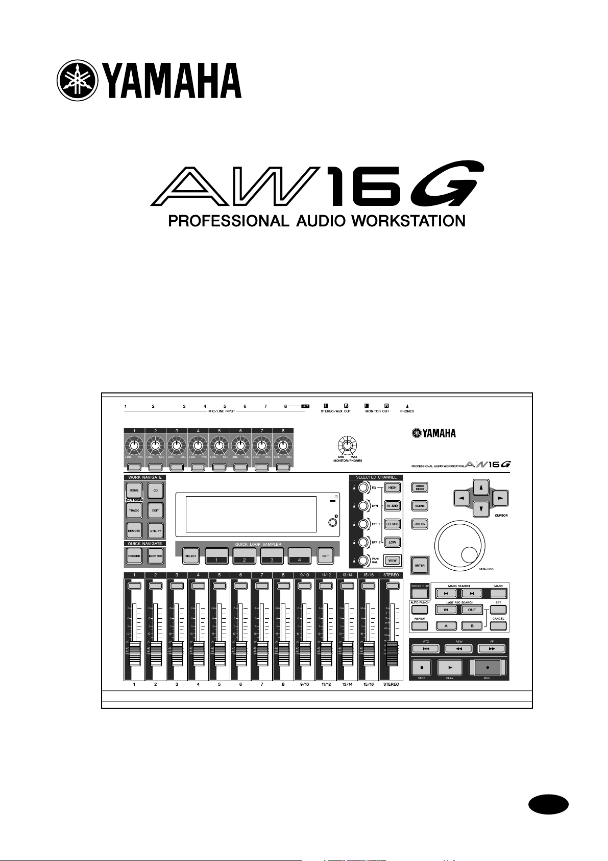
Parts of the AW16G and what they do .....................17
Top panel ...........................................................17
Rear panel ..........................................................21
Front panel .........................................................22
Basic operation on the AW16G.................................23
Viewing the display.............................................23
Accessing a screen/page/channel........................23
Switching a button on/off...................................24
Editing a value in the display ..............................24
Inputting text .....................................................24
Using the Selected Channel section ....................25
3 Listening to the demo song...........27
Connect external devices and turn on the
power ....................................................................27
Loading the demo song ...........................................28
Playing the demo song ............................................29
Mixing the demo song.............................................30
4 Recording to a sound clip ..............33
Connecting your instrument or mic .........................33
Adjusting the input level ..........................................34
Recording/playing a sound clip ................................35
5 Track recording .............................39
Creating a new song ................................................39
Direct recording and Bus recording..........................40
Assigning input signals to tracks (Direct
recording)..............................................................42
Assigning input signals to tracks (Bus recording) ......45
Enabling the metronome .........................................47
Recording on a track ................................................48
Pairing input channels/track channels ......................49
Using the input library..............................................50
Using the EQ library .................................................52
Using the dynamics library .......................................53
6 Overdubbing.................................. 55
About overdubbing..................................................55
Assigning the input signal to a track.........................56
Instantly recalling an EQ library ................................56
Instantly recalling a dynamics library ........................57
Setting the mix balance and pan..............................57
Overdubbing ...........................................................58
Punch-in/out............................................................59
Manual punch-in/out .........................................59
Auto punch-in/out..............................................59
Using the Undo List..................................................61
Switching virtual tracks ............................................62
Saving the current song ...........................................63
Loading an existing song .........................................64
7 Various types of playback ............. 65
Using the locator......................................................65
Using markers ..........................................................67
Adjusting the position of a locate point or
marker ...................................................................68
Erasing a locate point or marker ...............................69
Repeatedly playing a specific region (the A-B
Repeat function) ....................................................70
Finding a location while you listen to the
sound (the Nudge function) ..................................71
Finding a location while you view the waveform ......72
8 Using libraries and scene
memories.................................. 73
About the libraries....................................................73
About scene memories.............................................73
Basic operation for libraries and scene memories......74
Storing library or scene data ...............................74
Recalling library or scene data.............................75
Deleting library or scene data .............................75
Naming library or scene data..............................76
Details on libraries and scene memory .....................77
Input library........................................................77
EQ library ...........................................................77
Dynamics library.................................................78
Effect library .......................................................78
Mastering library ................................................78
Sample library ....................................................78
Channel library ...................................................79
Scene memories .................................................79
Using the Recall Safe function ..................................80
9 Mixdown and bounce operations . 81
About mixdown and bouncing ................................81
Preparing for mixdown ............................................83
Using the internal effects via send/return .................84
Recording on the stereo track...................................86
Bounce (ping-pong) recording procedure ................87
Convenient functions during mixdown/bounce
operations..............................................................89
6
Page 7

Adding input signals or pad performances
during mixdown ..............................................89
Using meters to check the level of each
channel............................................................ 90
Viewing all parameters for a certain channel....... 90
Initializing a channel .......................................... 91
Editing the EQ parameters.................................. 92
Editing the dynamics parameters........................ 93
Editing the parameters of an internal effect ........ 94
Inserting an effect into a track channel ............... 96
10 Creating an audio CD ..................97
Creating an audio CD .............................................. 97
Types of media that you can use with the CD-
RW drive................................................................ 97
Methods of writing an audio CD.............................. 98
Basic settings for the CD-RW drive ........................... 99
Writing audio data (Track At Once) ....................... 100
Writing audio data (Disc At Once) .........................102
Finalizing CD-R/RW media ..................................... 104
Erasing CD-RW media............................................ 105
Playing an audio CD ..............................................106
11 Quick loop sampler.................... 107
About the quick loop sampler................................ 107
Using sample libraries ............................................109
Recording/playing a pad performance ................... 110
Importing from an audio CD/WAV file to a pad .....112
Importing from an audio track/stereo track to a
pad ..................................................................... 114
Sampling an external input signal.......................... 115
Editing the sample name ....................................... 117
Trimming the playback region ............................... 118
Switching the playback mode for each pad ........... 119
Using the Slice function .........................................120
Deleting an unwanted sample ...............................122
Copying or deleting a song ...................................140
Optimizing a song ................................................. 141
Creating a tempo map .......................................... 142
Importing data from an existing song.................... 144
Backing up songs and sample libraries ................... 145
Restoring songs or sample libraries ........................147
Exchanging song data with the AW4416/AW2816 148
14 MIDI and utility functions......... 149
What you can do using MIDI ................................. 149
Basic MIDI settings ................................................ 150
Transmitting the AW16G’s settings via MIDI
(Bulk Dump)........................................................ 154
Using the MIDI Remote function............................ 155
About the MIDI Remote function .....................155
Using the MIDI Remote function presets ..........155
Using the user-defined Remote function........... 157
Using the test tone oscillator.................................. 159
Digital input settings/Checking and initializing the
internal hard disk................................................. 160
Overall settings for the AW16G.............................. 162
15 Using the AW16G with
external devices ..................... 163
Using the AW16G with a “workstation synth”........ 163
Synchronizing the AW16G with the
workstation’s sequencer................................. 163
Recording/playing AW16G mix operations on
the workstation’s sequencer........................... 164
Switching AW16G scenes from the
workstation’s sequencer................................. 165
Remotely controlling a tone generator module...... 166
Using external effects............................................. 167
Connecting an MD recorder .................................. 169
Mixing down to an MD recorder...................... 169
Recording audio data from an MD recorder ..... 170
12 Track editing .............................123
What you can do using editing commands............ 123
Basic procedure for track editing ...................... 124
List of editing commands....................................... 126
ERASE............................................................... 126
DELETE............................................................. 127
INSERT ............................................................. 127
COPY ............................................................... 128
MOVE ..............................................................129
EXCHANGE ......................................................130
TIME COMP/EXP (Time Compression/
Expansion) .....................................................130
PITCH CHANGE................................................ 131
EXPORT............................................................ 131
Exporting WAV files and importing audio CD or
WAV files .............................................................132
Exporting WAV files.......................................... 132
Importing from an audio CD or WAV file.......... 133
13 Song management..................... 137
About songs ..........................................................137
Editing the song name........................................... 138
Editing various settings for the song ......................139
Appendix ........................................ 171
Input library list ..................................................... 171
Mastering library list .............................................. 172
EQ library list ......................................................... 173
Dynamics Parameters ............................................ 174
Dynamics library list............................................... 177
Effects library list.................................................... 178
Effects Parameters.................................................. 180
Sample library list ..................................................192
Troubleshooting .................................................... 194
Display message list ............................................... 198
About the CD-ROM included with the AW16G ...... 200
Caution............................................................ 200
Contents of the CD-ROM................................. 200
Restoring the internal hard disk to the
factory-set condition ......................................200
Installing a remote file...................................... 201
MIDI data format................................................... 204
MIDI Implementation Chart................................... 211
Specifications......................................................... 212
Dimensions............................................................ 214
Index..................................................................... 215
Block diagram........................................................ 218
7
Page 8

Contents
8
Page 9

Note
■
■
■
■
■
■
Chapter 1
Before you start
This chapter explains what you should know before you begin using
the AW16G.
Introduction
Check the included items
The AW16G package contains the following items. If any
are missing, please contact your dealer.
•The AW16G
•AC adaptor (PA-300)
• Owner’s manual (this book)
• CD-ROM
Copyright
This product incorporates and bundles computer programs and contents in which Yamaha owns copyrights or
with respect to which it has license to use other’s copyrights. Such copyrighted materials include, without limitation, all computer software, styles files, MIDI files,
WAVE data and sound recordings. Any unauthorized use
of such programs and contents outside of personal use is
not permitted under relevant laws. Any violation of copyright has legal consequences. DON’T MAKE, DISTRIBUTE OR USE ILLEGAL COPIES.
Trademarks
• Macintosh is a registered trademark of Apple Computer, Inc. USA in the United States and other countries.
•Windows is a registered trademark of Microsoft Corporation USA in the United States and other countries.
• Cubase VST is a trademark of Steinberg Media Technologies AG.
• Logic Audio is a trademark of Emagic Soft- and Hardware GmbH.
• Cakewalk is a registered trademark of Twelve Tone
Systems, Inc.
• ProTools is a trademark or registered trademark of
Avid Technology, Inc. and affiliated companies.
• Other company names and product names in this
document are the trademarks or registered trademarks of their respective owners.
Yamaha website
http://www.yamahasynth.com
http://www.yamaha.co.jp/product/proaudio/homeenglish/
Yamaha manual library
http://www2.yamaha.co.jp/manual/english/
Remember to back up your data
Storing produced data
Produced data can be lost due to breakdown or mistaken
operation. We recommend that you store all important
data on CD-R or CD-RW discs or other external storage
medium.
Note
A CD-RW drive (the separately sold CDRW16G) is necessary in order to back up data.
Responsibility for loss of data, etc.
Yamaha will accept no responsibility for any damages
(including consequential or incidental) incurred by the
customer or any third party as a result of loss or impairment of the data stored on the CD-R media, regardless of
whether such loss could have been or actually was foreseen by Yamaha.
Nor does Yamaha guarantee the media against any defect
that may render it unusable.
9
Page 10
Before you start
■
1
B
C
D
E
F
G
About the CD-RW drive
A CD-RW drive is a device that lets you create or play
audio CDs, backup and restore data from the internal
hard disk, and read data from a CD-ROM. An optional
CDRW16G can be installed in the AW16G. Please be
aware that other CD-RW drives cannot be installed in the
AW16G.
•Even if a CD-RW drive is operating normally, it may fail
a read or write operation approximately once in five
hundred times.
•Yamaha will take no responsibility for any damages,
direct or consequential, that may result from the use of
the above CD-RW drive.
Handling
Do not drop the drive or subject it to strong
physical shock.
Never touch the objective lens.
Be careful that the objective lens does not
become dusty or dirty.
If the objective lens becomes dusty, use a
commercially available blower etc. to blow the
dust off with clean air.
Before installing the drive, touch a grounded
metal object so that the drive is not damaged
by any static electricity that may be in your
body.
Since the inside of the drive contains powerful
magnetic circuitry, do not allow any magnetic
material to come near the drive. (In particular,
any metallic fragments, screws, or pins that
enter the drive mechanism will cause operation to fail.)
Do not press on the upper cover.
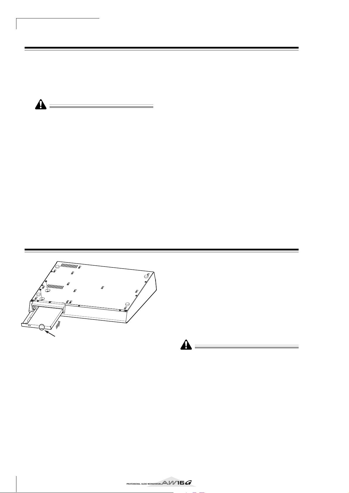
Installing the CD-RW drive
4
3
Push the drive here.
Turn off the power of the AW16G.
1
As described in “Turning the power off (shut down)”
( → p. 12), turn off the power of the AW16G. For
safety’s sake, also unplug the AC adaptor and the
AW16G from the electrical outlet.
Turn the AW16G over on its face.
2
Be careful not to drop the AW16G on the floor, or
damage the components of the top panel. Spread
out a soft cloth on a level surface, and stack magazines etc. to support each of the four corners of the
upside-down AW16G.
Insert the CD-RW drive into the slot.
3
Insert the CD-RW drive into the slot by pressing
slightly right of center on the back edge of the drive.
The slot cover swings open. When the CD-RW drive
reaches the back of the slot, continue applying pressure until you feel the connector click into place.
You will need to apply about as much pressure as
when pressing an elevator button.
Fasten the CD-RW drive with screws.
4
Use the two included screws to fasten the CD-RW
drive in place (“4” in the diagram at left).
Be sure to follow installation steps 1–4 exactly as
directed. In particular, reading and writing may not occur
correctly if the screws have not been tightened sufficiently.
10
Page 11

Note
■
Removing the CD-RW drive
4
3,5
CD-RW drive cover
Turn off the power of the AW16G.
1
As described in “Turning the power off (shut down)”
( → p. 12), turn off the power of the AW16G. For
safety’s sake, also unplug the AC adaptor and the
AW16G from the electrical outlet.
Turn the AW16G over on its face.
2
Be careful not to drop the AW16G on the floor, or
damage the components of the top panel.
Remove the CD-RW drive cover.
3
Remove the black screw that holds the CD-RW
drive cover in place (“3” in the diagram at left).
Do not lose the screw that you removed.
Pull the CD-RW drive out of the slot.
4
Remove the two screws that fasten the CD-RW
drive in place, and pull out the CD-RW drive (“4” in
the diagram at left).
Grasp here with your
thumb and first finger.
< Bottom of the CD-RW drive >
• Do not lose the screws that you removed.
• Be careful not to cut yourself on any sharp metal edge.
Attach the CD-RW drive cover.
5
Using the black screw that you removed in step 3,
attach the CD-RW drive cover.
The cover may crack
if you attempt to pull
out the CD-RW drive
by grasping the black
cover.
1
Before you start
Using the CD-RW drive
The CD-RW drive installed in the AW16G is shipped
with a protective pad on the disc tray to prevent it from
being damaged during transportation. Before you use the
AW16G, you must remove this protective pad.
To insert a disc into the CD-RW drive, press the eject
switch. The disc tray will open. Place the disc on the tray,
and gently push the disc tray in.
Note
The disc tray is ejected electrically. If the disc tray is not
ejected when you press the eject switch, turn on the
power of the AW16G and press the eject switch once
again.
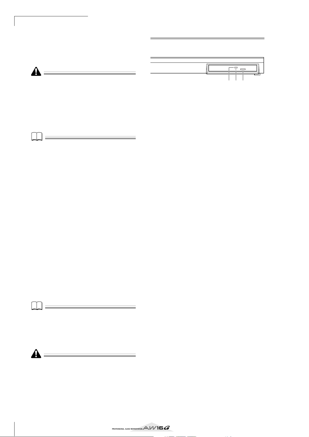
Eject buttonEject hole
Removing a CD in an emergency
If you are unable to remove the disc by pressing the eject
switch, insert a wire of less than 2 mm diameter (such as
a straightened paper clip) into the eject hole, and push
gently. However, pressing the eject switch will not eject
the disc when the AW16G is in the following states, so
do not use this method in such cases.
• When the AW16G's power is “STANDBY“
• When the disc is being accessed (data is being read,
written, or erased)
• While in CD PLAY mode
This removal method is for use in emergencies such as
when you cannot remove the disc due to a malfunction of
the disc tray or a power failure. Do not use this method
unnecessarily, since doing so will damage the CD-RW
drive.
11
Page 12
Before you start
Tip!
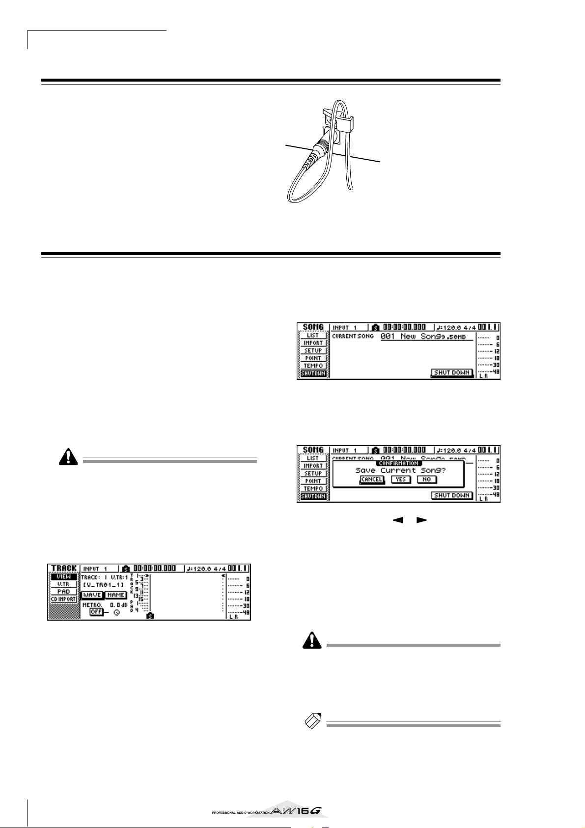
Connecting the AC adaptor
When connecting the included AC adaptor (PA-300), you
must first connect it to the DC IN jack of the AW16G,
and then to the AC wall outlet. After connecting the AC
adaptor to the AW16G, wrap the cable around the hook
as shown in the diagram. This will prevent the cable from
being accidentally pulled out, causing the AW16G to
unexpectedly lose power.
Turning the power on/off
DC IN
You must use the following procedure to switch the
power of the AW16G between ON and STANDBY. If you
fail to follow this procedure, the internal hard disk or
your external monitor system may be damaged.
■ Turning the power on
In a system that includes the AW16G, turn the power of
each device on in the following order.
1 External devices such as audio sources and
effect processors connected to the input/output jacks of the AW16G
B The AW16G itself
C The monitor system connected to the
AW16G’s output jacks
Before you turn on the power, make sure that the AC
adaptor is firmly connected to the AW16G and to the AC
outlet. If the power is disconnected while the AW16G is
being used, the AW16G itself or the hard disk may be
damaged.
When you turn on the power of the AW16G, an opening
screen will appear, and then the following screen will
appear.
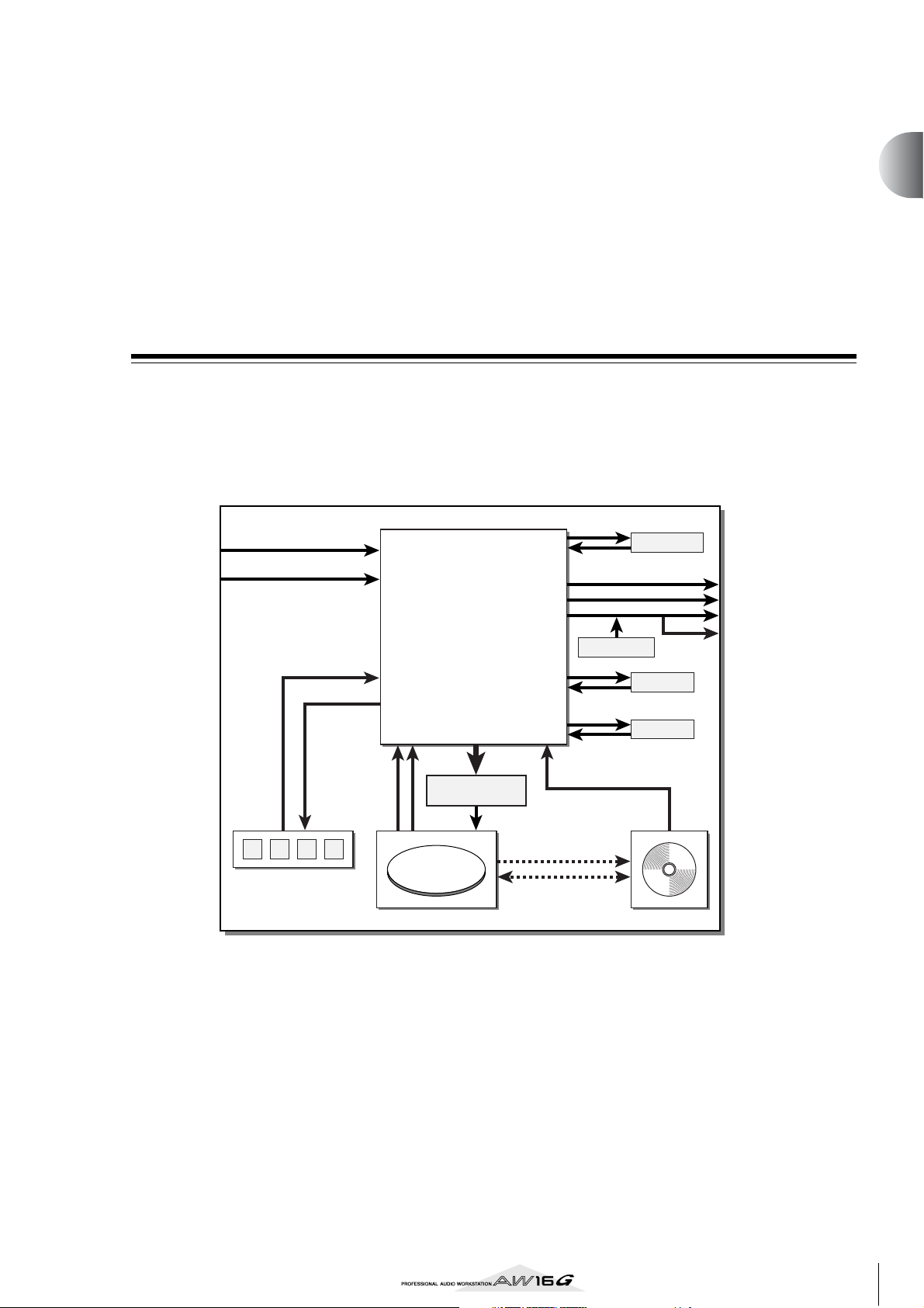
In the work navigate section located in the
1
upper left of the top panel, press the [SONG]
key several times to access the following
SHUTDOWN page.
Press the [ENTER] key located in the middle
2
right of the top panel.
A popup window will ask you whether you want to
save the current song.
Using the CURSOR [ ]/[ ] keys located in
3
the upper right of the top panel, move the
cursor (the blinking area in the screen) to the
YES button if you want to save the current
song, or to the NO button if you do not want
to save it. Then press the [ENTER] key.
■ Turning the power off (shut down)
In a system that includes the AW16G, turn the power of
each device off in the following order.
1 The monitor system connected to the
AW16G’s output jacks
B The AW16G itself
C External devices such as audio sources and
effect processors connected to the input/output jacks of the AW16G
When turning off the power of the AW16G, you must
perform the following “shut-down” procedure.
12
When the “Now safe to turn off...” message
4
appears, turn off the [POWER] switch located
on the rear panel.
If you turn off the power of the AW16G without performing the above shutdown procedure, not only will any
unsaved changes be lost, but you also risk damaging the
data on the hard disk, and damaging or drastically shortening the lifespan of the hard disk itself and the internal
CD-RW drive. Please use caution.
Tip!
A small amount of electrical current is flowing even when
the power is in STANDBY mode. If you will not be using
the AW16G for an extended period of time, be sure to
disconnect the AC adaptor from your AC outlet.
Page 13
Introducing the AW16G
This chapter describes the features of the AW16G, the name of each
part and its function, and introduces terminology you need to know
when using the AW16G.
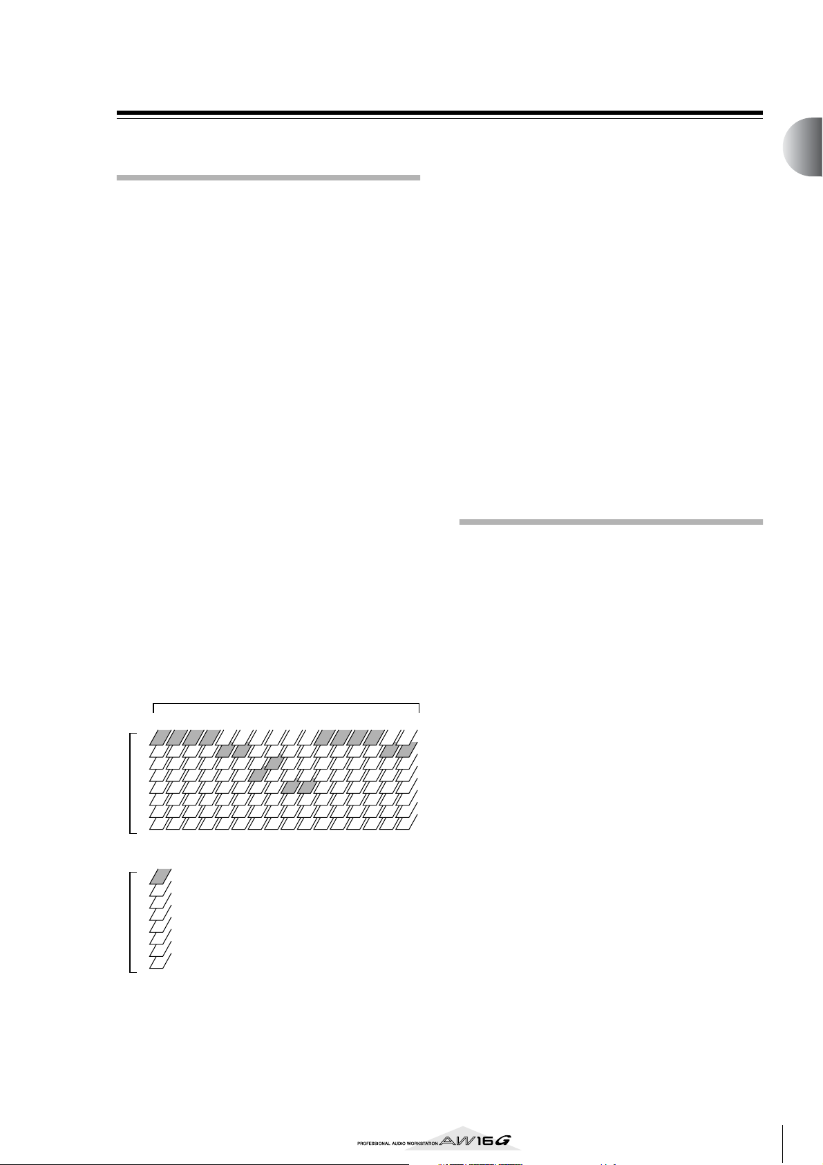
Features of the AW16G
The AW16G is an audio workstation that combines a digital mixer, multi-effect processor, hard disk recorder,
sampler, and CD-RW drive.
The following diagram shows the signal flow within the
AW16G.
Chapter 2
INPUT jacks 1–8
DIGITAL
STEREO IN jack
1 2 3 4
Quick loop sampler
×8
Input channels 1–8
×2
Track channels 1–16
Return channels 1/2
Pad channels 1–4
Buses L/R
AUX buses 1/2
Effect buses 1/2
×8
Stereo buses L/R
×2
Stereo output channel
Recorder input
patching
×2 ×16 ×16
Recorder
Mixer
×2
×2
×2
×2
×2
×2
×2
×2
×2
×2
CD Write
DATA
Backup/Restore
Import/Export
Sound clip
STEREO/AUX OUT jacks
DIGITAL STEREO OUT jack
MONITOR OUT jacks
PHONES jack
Metronome
Effect 1
Internal effects
Effect 2
CD Play
CD-RW drive
Now let’s take a more detailed look at each section of the
AW16G.
■ Mixer section
● Full-fledged mixer with 36 input channels
The AW16G contains a digital mixer with a total of
36 input channels, including analog inputs x 8, stereo digital input x 1, recorder tracks x 16, and effect
returns x 2. Audio quality is guaranteed by 24-bit AD/
DA and 32-bit internal processing. A Hi-Z input jack
for directly connecting an electric guitar or bass is
also provided.
● Totally redesigned operation
The AW16G is designed to be operated directly by
the musician (guitarist, vocalist, drummer etc.). With
a minimum number of steps, you can assign input
signals to tracks, switch the monitor signal, and
record with effects, EQ, and dynamics processing
applied.
13
Page 14

Introducing the AW16G
● Four-band EQ and dynamics processors on each
channel
Four-band full-parametric EQ and dynamics processing is provided on virtually every channel. You can
recall the desired preset from the library, and use the
panel knobs and keys to quickly adjust the settings.
● Two high-quality multi-effect units are built-in
The two built-in effect units deliver a wide variety of
effects including spatial-type effects such as reverb
and delay, modulation type effects such as chorus
and flanger, and guitar-type effects such as distortion
and amp simulation. These effects can be used either
via send/return, or inserted into a desired channel.
■ Recorder section
● 8-track simultaneous recording/16-track simulta-
neous playback
You can record multiple tracks of instruments one by
one, or set up multiple mics to record a drum set or a
live performance by an entire band. A stereo track for
direct mixdown of all 16 tracks is also provided, letting you manage the multi-track audio and the twotrack mix as a single package of data.
For the multi-tracks as well as the stereo track, you
can use eight virtual tracks for each track. When
recording parts or during mixdown, you can switch
virtual tracks to record multiple takes, and select the
best take later.
● Versatile editing functionality
Audio data recorded on a track can be copied,
moved, or edited using a variety of commands. You
can make detailed edits, or even make radical
changes to the structure of the song by using the
same riff repeatedly or increasing the number of choruses.
“Time Compression” lets you compress or expand the
time axis of the audio data in a range of 50%–200%.
“Pitch Change” lets you modify the pitch in a range
of one octave upward or downward. You can use the
Undo function to reverse the results of as many as the
last fifteen editing operations.
● A variety of Locate methods, and auto punch-in/out
Seven locate points (start/end, relative zero, A/B, in/
out) and 99 markers can be assigned at any desired
point in the song, for quick access via Locate operations. Auto punch-in/out and A-B repeat playback
functions are also provided. The AW16G also has a
metronome that follows the tempo map.
● Sound Clip function
The Sound Clip function lets you record and play
back an input signal without affecting the recorder
tracks. You can use this as a sketch for your ideas for a
song or arrangement.
■ Quick Loop Sampler section
The AW16G has a built-in pad-type sampler. You can
assign sixteen stereo waveforms to the four pads with
sample banks. Sampling uses the same 16-bit 44.1 kHz
high quality as recording. Audio tracks from the hard
disk, external input from the mixer, or WAV files from a
CD-ROM disc can also be loaded.
The timing at which each pad is pressed can be recorded
on a dedicated pad track, and edited later. Drum phrases
from the sample library can be assigned to pads, and you
can then record pad operations to use this function as a
simple rhythm machine.
The maximum polyphony is four stereo notes, and the
maximum playback time is a total of 44 seconds of stereo
for the entire Quick Loop Sampler.
■ CD-RW drive
A dedicated CD-RW drive (the CDRW16G, option) can
be installed in the AW16G. If this is installed, you can
produce an audio CD from the stereo tracks of the songs
recorded on the hard disk. Markers assigned within a
song can also be used as the track numbers of the CD.
You can even use advanced techniques such as assigning
more than one track number within a single song.
The CD-RW drive can also be used to backup/restore
songs, to play back audio CDs, and to load WAV data
from a CD-ROM.
14
Page 15
AW16G terminology
Recorder section
■ Tracks
A location where data is recorded is called a “track.” The
AW16G’s recorder section uses the following types of
track.
● Audio tracks
The physical tracks used to record and play back
audio data are called “audio tracks,” or simply
“tracks.” The AW16G has sixteen audio tracks. You
can record eight tracks simultaneously, and play back
16 tracks simultaneously.
● Stereo track
Independently from audio tracks 1–16, the AW16G
has a “stereo track” that records and plays a stereo
audio signal.
The stereo track is used mainly as a dedicated mixdown track for recording the final mix.
● Virtual tracks
Each audio track 1–16 and the stereo track consists of
eight tracks. Each of these eight tracks is called a “virtual track.” For the audio tracks and the stereo track,
only one virtual track can be recorded or played at
any time. However, you can switch virtual tracks to
continue recording other takes while preserving the
previously-recorded content.
The diagram below shows the concept of virtual
tracks. The horizontal rows indicate audio tracks 1–
16, and the vertical columns correspond to virtual
tracks 1–8. The shaded areas indicate the virtual track
that is currently selected for recording or playback.
Audio tracks
1
2 3 4 5 6 7 8 9 10 11 12 13 14 15 16
1
2
3
4
5
6
Virtual tracksVirtual tracks
7
8
Stereo track
1
2
3
4
5
6
7
8
■ Paired tracks
For audio tracks 9/10–15/16, adjacent pairs of tracks are
handled by the mixer as a single unit. These pairs of
tracks are referred to as “paired tracks.” A paired track
can be used to record a stereo source, or a dual-guitar
performance, etc.
■ Locate points/markers
Locations within a song that you specified in order to
execute a function such as auto punch-in/out or A-B
repeat playback are called “locate points.” Locate points
include the in/out points and the A/B points, and you can
use the keys of the Locate section to move instantly to
these points.
Independently of the locate points, you can assign
“markers” at desired locations within a song so that you
will be able to find these locations quickly. The AW16G
lets you set up to ninety-nine markers (1–99). By using
the keys of the Locate section you can move instantly to
the previous or next marker.
Mixer section
■ Channels
A signal route that processes a single signal within the
mixer and sends it to various sections is called a “channel.” The mixer section of the AW16G lets you use the
following channels.
● Input channels 1–8
These apply EQ and dynamics processing to the signals that are input from MIC/LINE INPUT jacks 1–8,
and send them to the recorder tracks or to the STEREO OUT jacks.
● Track channels 1–16
These channels apply EQ and dynamics processing to
the audio playback signals from audio tracks 1–16 of
the recorder, and send the signals to the stereo track
and the STEREO OUT jacks. You can also perform
“bounce recording” by sending these channels to different tracks.
● Return channels 1/2
These channels send the return signals from the internal effects to the stereo track and the STEREO OUT
jacks.
● Pad channels 1–4
These channels apply EQ and dynamics processing to
the playback of Quick Loop Sampler pads 1–4, and
send the signals to the stereo track and the STEREO
OUT jacks.
● Stereo output channel
This applies EQ and dynamics processing to the signal of the stereo bus (which combines the signals of
the various channels), and sends it to the stereo track
or to the STEREO OUT jacks. The same signal is also
output from the MONITOR OUT jacks and from the
PHONES jack.
2
Introducing the AW16G
15
Page 16

Introducing the AW16G
■ Paired channels
For track channels 9/10–15/16, pad channels 1–4, and
return channels 1/2, the parameters (except for pan and
phase) are always linked for adjacent pairs of channels.
These are called “paired channels.”
For input channels 1–8 and track channels 1–8, you can
also switch two adjacent odd-numbered/even-numbered channels to function as paired channels. The
parameters (except for pan and phase) of paired channels
will be linked, so that adjusting one parameter will cause
the same parameter of the other channel to follow.
■ Buses
A signal route that mixes the signals from multiple channels and send them to an output jack or recorder track
input is called a “bus.”
Unlike channels, which handle only a single signal, a
bus can combine multiple signals into one or two, and
send them to a destination. (The term “bus” comes from
the vehicle that carries numerous people simultaneously.)
The AW16G’s mixer section lets you use the following
buses.
● Stereo bus
This mixes the input signals to stereo, and sends them
via the stereo output channel to the stereo track of
the recorder or to the STEREO OUT jacks.
● AUX buses 1/2
These combine the signals from the various track,
input, return, and pad channels, and output them via
the STEREO/AUX OUT jacks to an external device.
Use these when you will use an external effect processor, or to create a mix differing from the stereo
channel for musicians to monitor.
● Effect buses 1/2
These combine the signals from the track, input,
return, and pad channels, and input them to built-in
effects 1 and 2. (However, it is not possible for the
return channel 1/2 signals to be returned to the input
of the same effect.)
● Buses L/R
These combine the signals of track, input channels,
and send them to recorder track inputs.
Quick Loop Sampler section
■ Sample banks and samples
In the Quick Loop Sampler section you can assign stereo
waveforms to the four pads, and strike the pads to play
them back. These stereo waveforms are called “samples.”
The memories to which the samples are assigned are
called “sample banks,” and each pad provides four sample banks (A–D).
■ Pad track
The AW16G can realtime-record and play back your
strikes on the pads. The memory that records these pad
operations is called the “pad track.” Unlike the tracks
that record audio, the pad track simply records the timing at which you “pressed a pad” or “released a pad.”
Overall
■ Songs
The smallest unit by which the AW16G manages a composition is called a “song.” When you save a song on the
hard disk, all data necessary for reproducing that song
will be saved; i.e., not just the audio data, but also mixer
settings and the samples used by the quick loop sampler.
You can return to the original state at any time by loading
the saved song.
■ Scenes and scene memories
A “scene” is a stored set of settings for the mixer section
and effects. The area of memory that holds the scenes is
called “scene memory,” and 96 scenes can be stored for
each song. Scene memories are saved on the hard disk as
part of the song.
■ Libraries
A “library” is an area of memory that stores individual
settings such as for EQ or dynamics. The AW16G has
separate libraries for EQ, dynamics, effect, channel,
input, and mastering settings. Each library is saved on the
hard disk as part of the song.
■ Tempo map
The “tempo map” records changes in tempo and time
signature that occur during the course of a song. The
tempo map is saved on the hard disk as part of the song.
16
■ System data
Various global settings that apply to all songs are collectively referred to as “system data.” System data is stored
on the hard disk independently of the individual songs.
Page 17
Parts of the AW16G and what they do
This section explains the names and functions of the various items on the AW16G’s top panel, rear panel, and
front panel.
Top panel
2
Introducing the AW16G
Work Navigate section
(P. 18)
Input/output section
(P. 18)
Display (P. 18)
Selected Channel section
(P. 19)
Data entry/control section
(P. 20)
Quick Navigate section
(P. 18)
Quick Loop Sampler
section (P. 18)
Mixer section
(P. 19)
Locate section
(P. 20)
Transport section
(P. 21)
17
Page 18
Introducing the AW16G
■ Input/output section
1
2
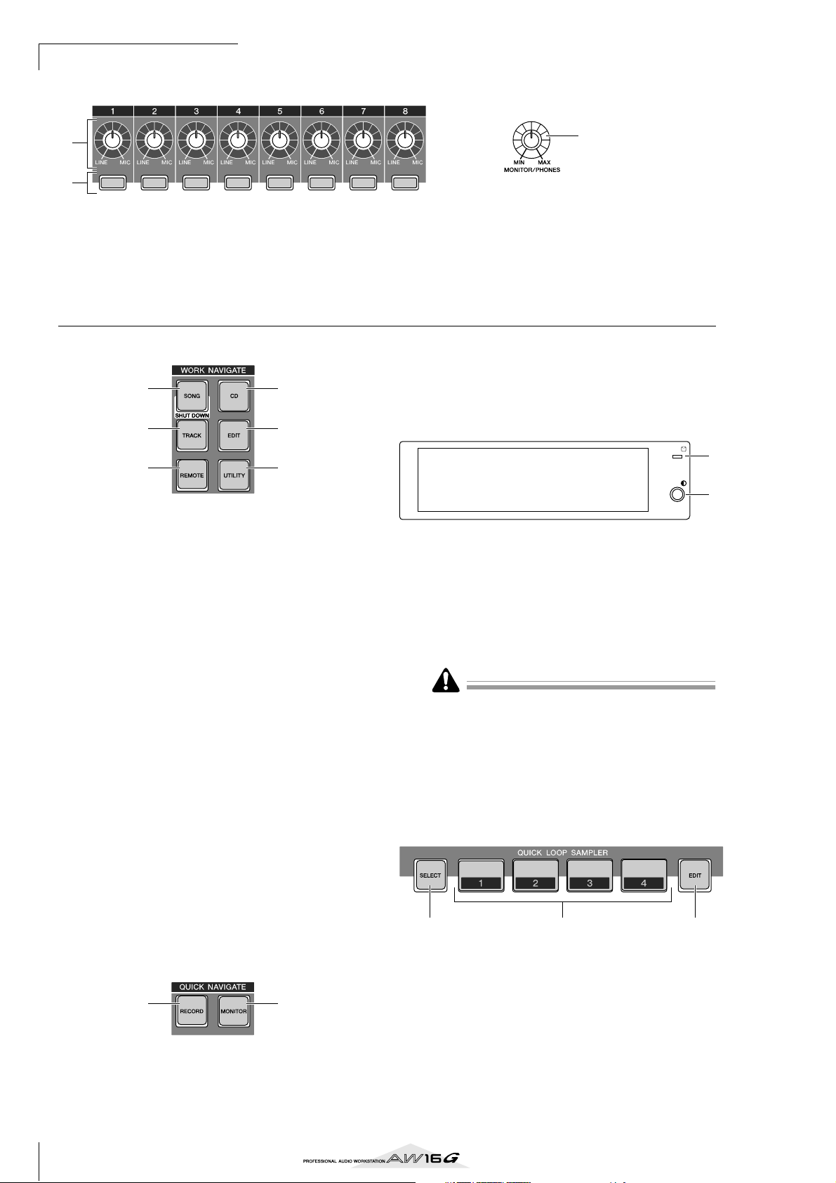
1 [GAIN] knobs 1–8
These adjust the sensitivity of the signals that are
input from the rear panel MIC/LINE INPUT jacks 1–8.
B [INPUT SEL] keys 1–8
These keys select the mixer input channel that you
will operate.
■ Work Navigate section
1
3
5
1 [SONG] key
This key accesses the SONG screen, where you can
save or load songs, and perform the shut-down procedure.
B [CD] key
This key accesses the CD screen, where you can
write or play an audio CD, and backup or restore
data.
C [TRACK] key
This key accesses the TRACK screen, where you can
check whether each track contains data, and switch
the virtual tracks that will be used for recording and
playback.
D [EDIT] key
This key accesses the EDIT screen, where you can
copy or erase tracks.
E [REMOTE] key
This key accesses the REMOTE screen, where you
can use the front panel faders and [TRACK SEL]
keys to control an external MIDI device or
sequencer software on your computer.
F [UTILITY] key
This key accesses the UTILITY screen, where you
can make MIDI, oscillator, and digital input settings, and format the hard disk.
2
4
6
■ Quick Navigate section
21
1 [RECORD] key
This key accesses the RECORD screen, where you
can quickly assign the signal to be recorded to the
input of each track, and make settings for recording.
3
C [MONITOR/PHONES] knob
This knob adjusts the level of the signal that is output from the MONITOR OUT jacks and the
PHONES jack.
B [MONITOR] key
This key accesses the MONITOR screen, where you
can quickly select the signal to be monitored, or
switch the stereo track playback on/off.
■ Display
1
2
This is a backlit liquid crystal display that indicates the
current operating status or the settings of the various
parameters. The screens that are displayed will depend
on the front panel keys and knobs that are operated.
1 Access indicator
This indicator indicates the access status of the
internal hard disk. When the hard disk is being read
or written, this indicator will light.
Never turn off the power of the AW16G when the access
indicator is lit. Doing so will not only damage the data on
the internal hard disk, but may also damage the hard disk
itself. When you want to turn off the power of the AW16G,
you must perform the shutdown procedure (→ p. 12).
B Contrast
Adjusts the brightness of the display.
■ Quick Loop Sampler section
1 32
1 [PAD SEL] key
Hold down this key and press a pad 1–4 to select a
pad for operations.
B Pads 1–4
Each of these pads plays back the sample that has
been assigned to it.
C [SAMPLE EDIT] key
This key accesses the SAMPLE screen, where you
can make settings and perform operations for the
quick loop sampler.
18
Page 19
■ Mixer section
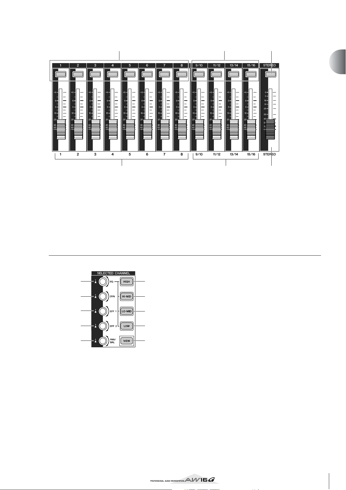
1
4 5
1 [TRACK SEL] keys 1–8
B [TRACK SEL] keys 9/10–15/16
C [STEREO SEL] key
Use these keys to select the mixer track channels or
recorder tracks that you want to control.
2 3
2
Introducing the AW16G
6
D Faders 1–8
E Faders 9/10–15/16
Normally, these faders adjust the playback level of
each recorder track. By changing the internal settings, you can also use these faders to control the
input levels of input channels 1–8 and pads 1–4.
F [STEREO] fader
This adjusts the output level of the stereo bus.
■ Selected Channel section
1
2
3
4
5
1 [EQ] knob
Turning this knob will adjust the EQ (equalizer) gain
for the currently selected channel. You can press
this knob to access the EQ screen, where you can
adjust all of the EQ settings.
B [DYN] knob
Turning this knob will adjust the dynamics depth for
the currently selected channel. You can press this
knob to access the DYN screen, where you can
adjust all of the dynamics settings.
6
7
8
9
J
C [EFF 1] knob
D [EFF 2] knob
Turning these knobs will adjust the amount of signal
that is sent from the currently selected channel to
the internal effects 1 and 2 (i.e., effect send levels 1
and 2). You can press these knobs to access the
EFF1 or EFF2 screens, where you can adjust the
parameters of the internal effects.
E [PAN/BAL] knob
Turning this knob will adjust the pan of the currently selected channel (or the balance of the stereo
output channel). You can press this knob to access
the PAN screen, where you can adjust pan for multiple channels.
F [HIGH] key
G [HI-MID] key
H [LO-MID] key
I [LOW] key
These keys select one of the four EQ bands (HIGH,
HI-MID, LO-MID, LOW) to be adjusted.
J [VIEW] key
This key accesses the VIEW screen, where you can
check the level of each channel, or perform onscreen adjustments to the faders and other mix
parameters of each channel.
19
Page 20
Introducing the AW16G
Tip!
■ Data entry/control section
1
2
3
5
6
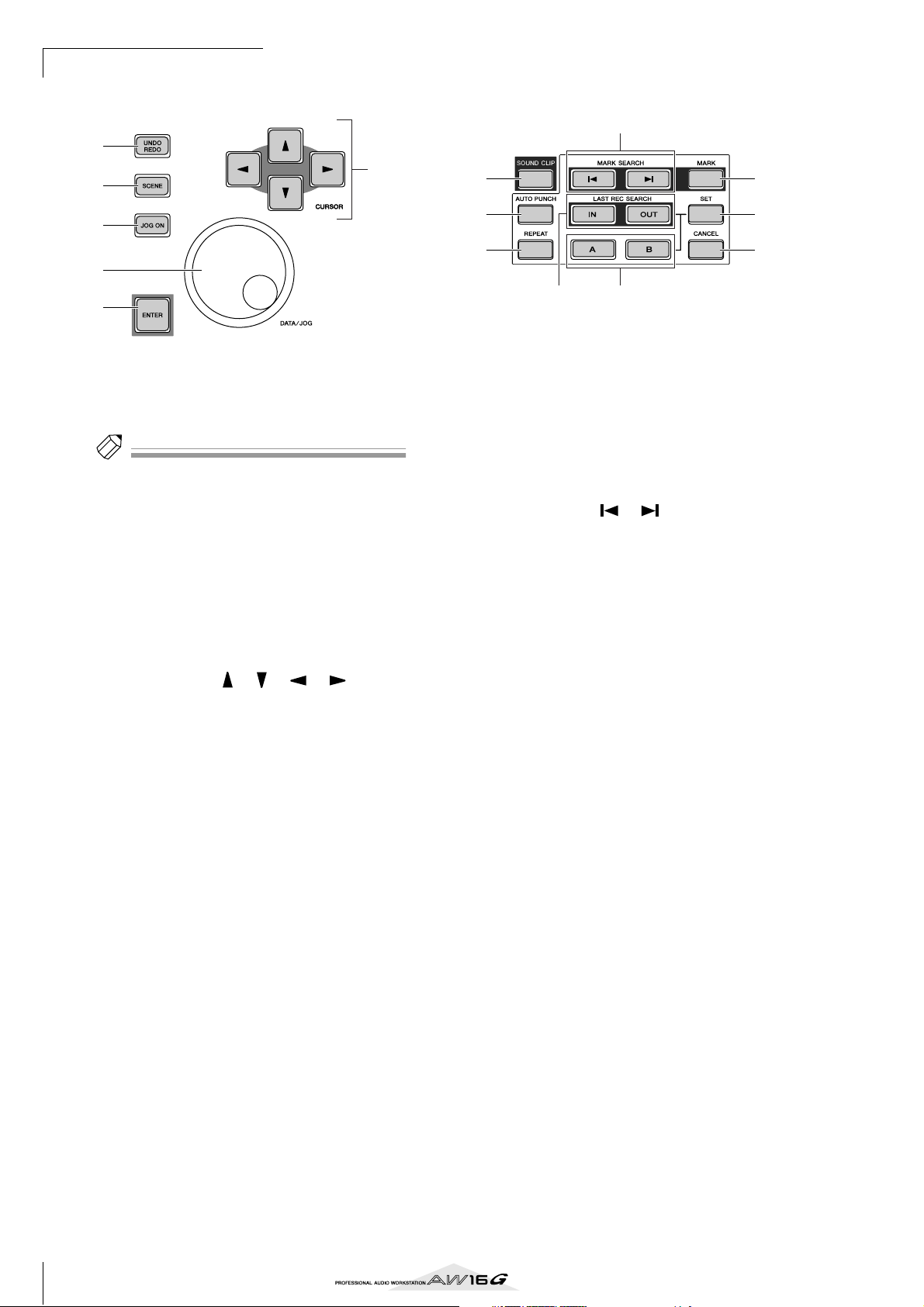
1 [UNDO/REDO] key
This key cancels the results of a recording or track
editing operation (Undo), or re-executes a cancelled operation (Redo).
Tip!
• This key will light if Undo can be performed.
• If you press and hold this key, the UNDO LIST screen
will appear. Here you can turn the [DATA/JOG] dial to
revert as many as the last fifteen operations (→ p. 61).
B [SCENE] key
This key accesses the SCENE screen, where you can
save or recall scene memories.
C [JOG ON] key
This key is an on/off switch for the Nudge function
(→ p. 71) which uses the [DATA/JOG] dial (5).
When this function is on, the key will light.
D [CURSOR] keys ([ ]/[ ]/[ ]/[ ] keys)
These keys move the cursor in the screen (the blinking frame) to select a specific item.
E [DATA/JOG] dial
Use this dial to change the value of a parameter. If
the [JOG ON] key (3) is on, this dial operates the
Nudge function.
F [ENTER] key
Use this key to operate a button displayed in the
screen, or to execute a specific function.
4
■ Locate section
4
1
2
3
5
1 [SOUND CLIP] key
This key accesses the CLIP screen, where you can
record or play sound clips.
B [AUTO PUNCH] key
This key switches the audio punch-in/out function
on/off, letting you automate recording.
C [REPEAT] key
This key switches the A-B repeat function on/off, letting you repeatedly play a specified region.
D MARK SEARCH [ ]/[ ] keys
These keys search for markers placed within the
song.
E [IN]/[OUT] keys
These keys specify the points at which auto punchin/out recording will begin (the In point) and end
(the Out point). These keys can also be used as
locate keys to move directly to the In point or Out
point.
F [A]/[B] keys
These keys specify the points at which the Repeat
function will begin (point A) and end (point B).
These keys can also be used as locate keys to move
directly to point A or point B.
G [MARK] key
This key places a mark at the current location of the
song.
H [SET] key
Use this key in conjunction with the [IN]/[OUT]
keys or the [A]/[B] keys to register the current location as a locater.
I [CANCEL] key
Use this key in conjunction with the [IN]/[OUT]
keys or the [A]/[B] keys to cancel a locater that you
registered.
6
7
8
9
20
Page 21
■ Transport section
Tip!
12 3
4 5 6
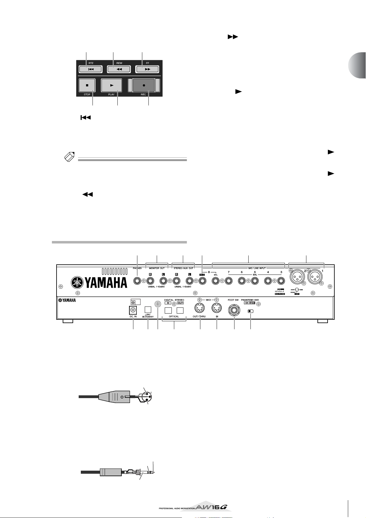
1 RTZ [ ] key
This key moves directly to the relative zero time
location. Used in conjunction with the [SET] key,
this registers the current location as the relative zero
time.
Tip!
Broadly speaking, the times displayed in the AW16G’s
counter can be either absolute time (ABS) or relative
time (REL). The absolute time zero location is fixed, but
the relative time zero location can be freely specified.
B REW [ ] key
This key rewinds the current location. Each time
you press this key, you will alternate between 8x
speed and 16x speed.
C FF [ ] key
This key fast-forwards the current location. Each
time you press this key, you will alternate between
8x speed and 16x speed.
D STOP [■] key
This key stops playback, recording, fast-forward, or
rewind.
E PLAY [ ] key
If you press this key while the recorder is stopped,
playback will begin.
If you press this key during fast-forward or rewind,
normal-speed playback will begin.
If you press this key during recording, recording
will stop and playback will resume (“punch-out”).
F REC [●] key
If you hold down this key and press the PLAY [ ]
key while the recorder is stopped, recording will
begin.
If you hold down this key and press the PLAY [ ]
key during playback, you will switch from playback
to recording (“punch-in”).
2
Introducing the AW16G
Rear panel
1 MIC/LINE INPUT (XLR) jacks 1/2
These are XLR-3-31 type balanced input jacks. The
nominal input level is –46 to +4 dB. Mics, direct
boxes, or line level devices with balanced output
jacks can be connected here. The pin configuration
is shown below.
Male XLR connector
B MIC/LINE INPUT (TRS phone) jacks 3–8
These are TRS phone type 1/4" input jacks (balanced). The nominal input level is –46 to +4 dB.
Devices such as synthesizers or rhythm machines
with unbalanced outputs can also be connected
here. The pin configuration is shown below.
1/4" TRS phone plug
1 (ground)
2 (hot)
Ring (cold)
3 (cold)
Tip (hot)
145 236
8 7M LN J 9K
C MIC/LINE INPUT jack 8 (Hi-Z)
This is a high impedance 1/4" phone input jack
(unbalanced). The nominal input level is –46 to +4
dB. An instrument with high output impedance
such as an electric guitar or bass with passive-type
pickups can be connected here.
D STEREO/AUX OUT jacks
These are 1/4" phone output jacks (unbalanced) that
output the signals of the stereo bus or AUX bus 1/2.
E MONITOR OUT jacks
These are 1/4" phone output jacks (unbalanced) for
connection to your monitor setup, such as a stereo
system or powered speakers.
F PHONES jack
This is a 1/4" TRS phone output jack for connecting
your headphones for monitoring.
Sleeve (ground)
21
Page 22
Introducing the AW16G
Note
Note
G PHANTOM +48V switch
This switch supplies phantom power to MIC/LINE
(XLR) jacks 1/2.
Turn this switch on if you connect condenser mics
requiring external +48V power to MIC/LINE INPUT
(XLR) jacks 1/2.
•You must turn this switch off if a device not requiring
an external power supply is connected to the INPUT
(XLR) 1/2 jacks.
• If phantom power is turned on, power will be supplied
to both the INPUT (XLR) 1/2 jacks.
H FOOT SW jack
A separately sold foot switch (Yamaha FC5) can be
connected here to control transport operations such
as start/stop, or to perform punch-in/out.
Note
The appropriate operation may not occur if you use a
foot switch other than the Yamaha FC5 (or equivalent).
I MIDI IN connector
J MIDI OUT/THRU connector
These connectors allow MIDI messages to be
exchanged with external devices.
MIDI IN receives MIDI messages.
MIDI OUT/THRU can be internally switched to
function either as a MIDI OUT jack (which transmits MIDI messages generated within the AW16G)
or MIDI THRU jack (which re-transmits messages
that are received at the MIDI IN jack).
K DIGITAL STEREO IN/OUT jacks
These are optical jacks that allow digital audio signals to be exchanged with external devices. They
support the IEC958 consumer format.
L Grounding terminal
This is a terminal for electrically grounding the
AW16G. To prevent electrical shock, you must connect this terminal to an electrical ground before you
plug the AC adaptor into an AC outlet. Grounding
will also help prevent hum and noise.
M POWER switch
This switches the power between ON and
STANDBY.
Front panel
■ CD-RW drive
123
1 Eject button
This switch ejects the disc tray.
B Eject hole
This hole allows you to open the disc tray manually.
C Access indicator
This indicator will light while the CD inserted in the
drive is being accessed.
Note
When switching the power of the AW16G between ON
and STANDBY, you must follow the “Turning the power
on/off” (→ p. 12) procedures described.
N DC IN connector
Connect the included AC adaptor (PA-300) to this
connector.
Use only the included AC adaptor (PA-300) for this unit.
Using other types may be a fire and electrical shock hazard.
22
Page 23
Basic operation on the AW16G
Tip!
This section explains basic operations on the AW16G.
Viewing the display
The display of the AW16G shows the following information.
12 354
1 Screen name
This is the name of the currently selected screen.
B Selected channel
This indicates the mixer channel that is selected for
operations. The display has the following significance.
TRACK 1–8 ...........................Track channels 1–8
TRACK 9/10–15/16...............Track channels 9/10–15/16
INPUT 1–8............................Input channels 1–8
STEREO.................................Stereo output channel
PAD 1–4................................Pad channels 1–4
Operating the knobs or keys of the Selected Channel section will edit the parameters of the channel
that is selected here.
C Counter (left side)
This indicates the current location within the song.
When the AW16G is in the default state, this
counter will indicate the absolute time (the time
from where you began recording the song) in units
of hours/minutes/seconds/milliseconds. At the left
of this value is displayed the locate point or marker
that was passed most recently.
D Counter (right side)
This indicates the current location within the song
in units of measures/beats. The measures/beats are
calculated according to the tempo and time signature specified in the tempo map for the song. The
current tempo and time signature are displayed at
the left of this value.
E Main screen
The information displayed in this area will depend
on the key that was last pressed. The following types
of object are displayed in the main screen.
● Cursor
The blinking frame within the display is
called the “cursor.” When an object in the
screen is enclosed by the cursor, that
object is selected for operations.
● Buttons
Buttons in the display are used to
switch a parameter on/off, to select
one of multiple choices, or to execute a specific function. A button
that is currently on will be displayed in black with white text. A
button that is currently off will be
displayed in white with black text.
● Knob/fader/parameter display area
The knob/fader/parameter display area within the
display is used to edit the value of the corresponding parameter.
Knob fader parameter display
area
● Page display area
Most screens are divided by function into two or more “pages.” The
page display area lists the pages
that can be selected within that
screen. The name of the currently
selected page is highlighted.
Accessing a screen/page/channel
When you want to edit an internal setting of the AW16G,
or to edit a parameter that cannot be operated by a fader
or knob shown in the display, you will need to access the
desired screen and page.
Press the key or knob for the desired screen.
1
The keys and knobs of various sections listed below
have their own screens, and the corresponding
screen will be displayed when you press a key or
knob.
• All keys in the Work Navigate section
• All keys in the Quick Navigate section
•The [VIEW] key of the Selected Channel section
• All knobs of the Selected Channel section
•The [SAMPLE EDIT] key of the Quick Loop Sampler section
Tip!
When you switch screens, the page that was last used in
that screen will be displayed.
2
Introducing the AW16G
23
Page 24
Introducing the AW16G
To switch pages within a screen, you can
2
either repeatedly press the same key as in
step 1, or hold down the same key as in step
1 and use the CURSOR [ ]/[ ] keys.
If there are more pages than can
be shown in one screen, an
arrow like the following will
appear in the page display area.
This arrow means that one or
more additional hidden pages
exist in that direction.
To access a hidden page, hold down the same key
as in step 1, and press the [CURSOR] key of the
same direction as the arrow.
In pages that display a list of parameters for multiple
channels, the screen may be divided into a page for
the input channels/pad channels and a page for the
track channels, since not all of the parameters can
be shown in a single screen. In this case, use the
[INPUT SEL] keys, pads 1–4, or [TRACK SEL] keys
to select the channels that you want to view.
Switching a button on/off
Here’s how to switch a button in the screen on/off.
Use the [CURSOR] keys to
1
move the cursor to the
desired button in the
screen.
Press the [ENTER] key.
2
The button will be switched on/
off.
If you move the cursor to a button that executes a specific
function and then press the
[ENTER] key, that function will
be executed.
Editing a value in the display
Here’s how to edit the value of a fader, knob, or parameter shown in the display.
Use the [CURSOR]
1
keys to move the cursor to the desired
fader, knob, or parameter value.
Turn the [DATA/JOG]
2
dial to edit the value.
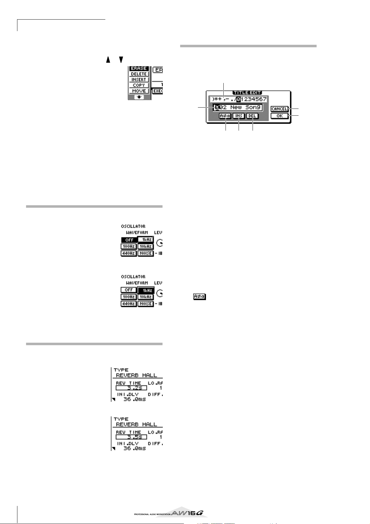
Inputting text
When you create a new song or save a scene memory or
library setting, a popup window will appear, allowing
you to assign a name for the song or setting.
2
1
5 6 7
This popup window contains the following items and
functions.
1 Text input box
This box lets you input characters, numerals, and
symbols. When you save the data for the first time,
the box will contain a default name.
You can input a scene/library name or song name of
up to twelve characters.
B Text palette
This displays the characters, numerals, and symbols
that can be input in the text input box.
C CANCEL button
If you move the cursor to this button and press the
[ENTER] key, you will return to the previous screen
without changing the name.
D OK button
If you move the cursor to this button and press the
[ENTER] key, the scene/library will be saved or the
new song will be created.
E button
If you move the cursor to this button and press the
[ENTER] key, the character that is currently selected
in the text input box will be switched between
uppercase and lowercase.
F INS button
When you move the cursor to this button and press
the [ENTER] key, a space will be inserted at the
location of the currently selected character (underlined), and subsequent characters will move one
character backward.
G DEL button
When you move the cursor to this button and press
the [ENTER] key, the currently selected character
(underlined) will be deleted, and subsequent characters will move one character forward.
To assign a new name, use the [CURSOR] keys to
move the cursor in the text input box to the character that you want to change, and turn the [DATA/
JOG] dial to select a character.
When you have finished inputting the name, move
the cursor to the OK button and press the [ENTER]
key to apply the new name.
3
4
24
Page 25
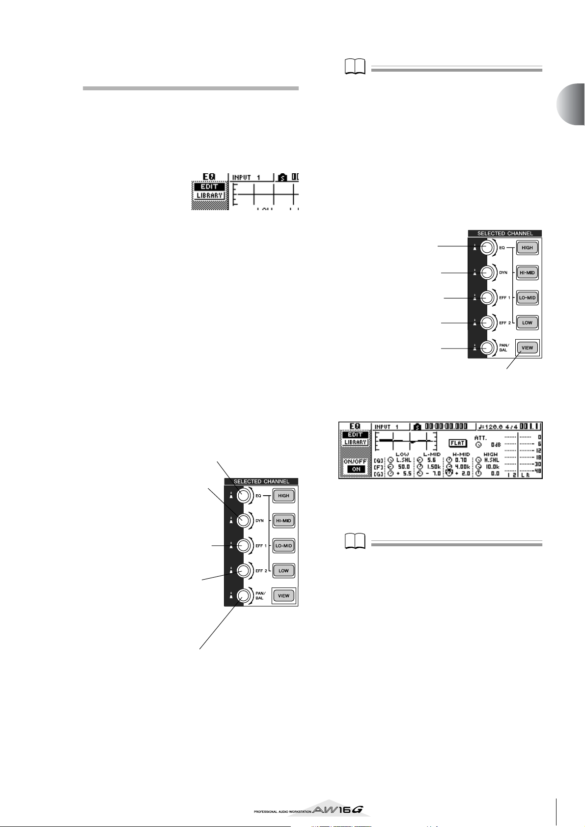
Using the Selected Channel sec-
Note
Note
tion
You can use the knobs and keys of the Selected Channel
section to directly operate the mix parameters (EQ,
dynamics, pan, etc.) of the currently selected channel.
Use the [TRACK SEL] keys, [INPUT SEL] keys,
1
[STEREO SEL] keys, or pads 1–4 to select the
channel that you want to operate.
When using the
Selected Channel
section, you must
first select the
channel that you
want to operate. The currently selected channel is
indicated in the upper left of the screen.
The channels correspond to each key or pad as follows.
[TRACK SEL] keys 1–8...........Track channels 1–8
[TRACK SEL] keys
9/10–15/16...........................Track channels 9/10–15/16
[INPUT SEL] keys 1–8 ...........Input channels 1–8
[STEREO SEL] key..................Stereo output channel
Pads 1–4................................Pad channels 1–4
According to the parameter you want to edit,
2
turn the five knobs of the Selected Channel
section.
The following items will change when you turn
each knob.
Turn the [EQ] knob
This changes the amount of boost/cut for the selected
EQ band. To select the EQ band, use the [HIGH], [HIMID], [LO-MID], and [LOW] keys located at the right.
Note
• Simply turning the knobs of the Selected Channel section will not cause the screen to change.
• If you turn the [DYN] knob immediately after recalling
a preset library that includes dynamics settings, multiple dynamics parameters will change simultaneously,
affecting the way in which dynamics processing is
applied. The depth of this change will depend on the
library that is recalled.
If you want to access the screen for a param-
3
eter and edit it in greater detail, press one of
the five knobs or the [VIEW] button.
Pressing each knob or button will access the following screens.
Press the [EQ] knob
The EQ screen will appear.
Press the [DYN] knob
The DYN screen will appear.
Press the [EFF 1] knob
The EFF 1 screen will appear.
Press the [EFF 2] knob
The EFF 2 screen will appear.
Press the [PAN/BAL] knob
The PAN screen will appear.
Press the [VIEW] key
The VIEW screen will appear.
● EQ screen EDIT page
2
Introducing the AW16G
Turn the [DYN] knob
This changes the depth of dynamics processing.
Turn the [EFF 1] knob
This adjusts the level of the signal
that is sent from that channel to
internal effect 1. (If the stereo output
channel is selected, this adjusts the
return level from internal effect 1.)
Turn the [EFF 2] knob
This adjusts the level of the signal
that is sent from that channel to
internal effect 2. (If the stereo output
channel is selected, this adjusts the
return level from internal effect 2.)
Turn the [PAN/BAL] knob
This adjusts the pan of the signal that is sent from that
channel to the stereo bus. (If the stereo output channel is selected, this adjusts the balance of the left and
right channels.)
Move the cursor in the screen to the desired
4
parameter, and use the [DATA/JOG] dial or
the [ENTER] key to operate the parameter.
Note
• If you change individual parameters in the DYN screen,
the parameter that you operate last will be assigned to
the [DYN] knob.
• If you want to return to the state in which turning the
[DYN] knob will adjust multiple parameters simultaneously, you must once again recall the library containing the dynamics settings you recalled prior to editing
in the DYN screen.
25
Page 26

Introducing the AW16G
26
Page 27
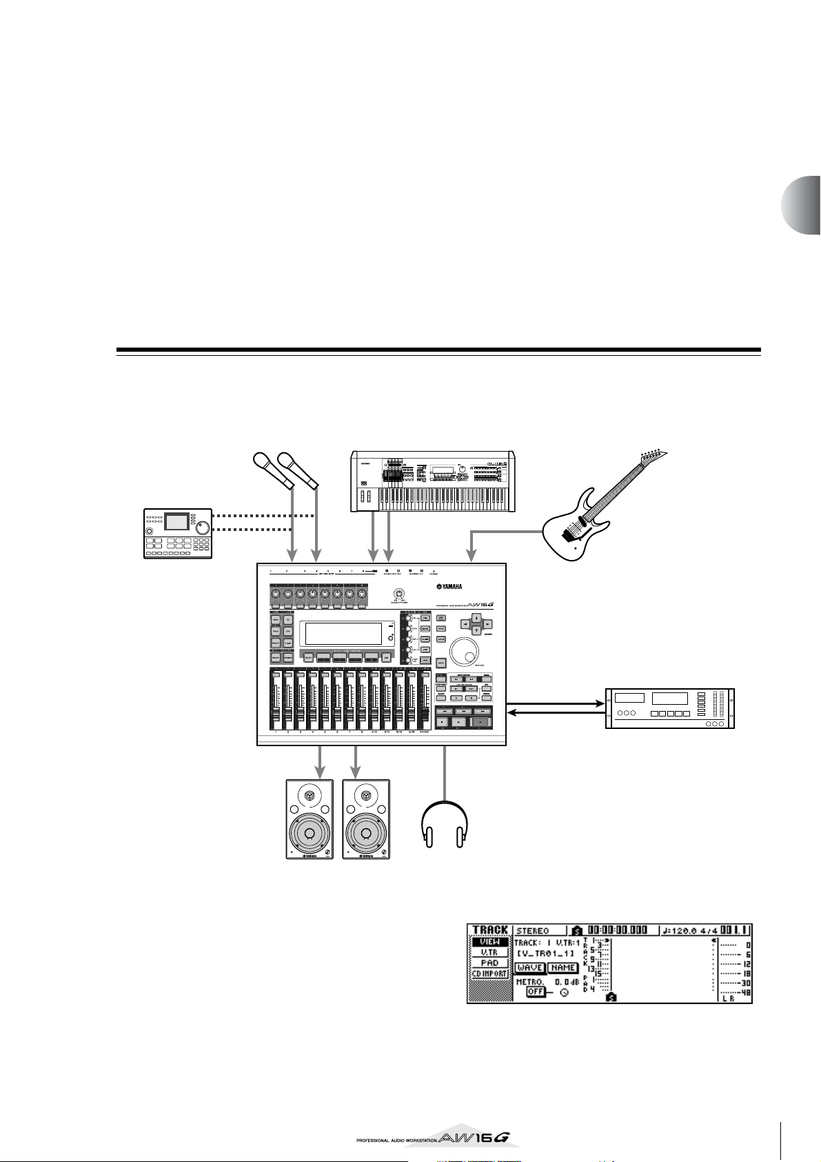
Chapter 3
Listening to the demo song
When the AW16G is shipped from the factory, its hard disk contains
a demo song. This chapter explains how to play back the demo song
while you operate the faders and keys of the front panel.
Connect external devices and turn on the
power
The following diagram shows a typical example of connections to the AW16G. Connect your mics, instruments,
and external devices as shown in this diagram.
SynthesizerMics
MUSIC
SYNTHESIZER
PRODUCTION
Sequencer
Sampling
Integrated
Real-timeExternalControl
Surface
Modular
SynthesisPlug-in
SONG SCENE
REC
System
Rhythm machine
INPUT 1 2 3–8
MONITOR OUT
VOL VOL
Monitor system
When you have finished making connections, turn on
the power switch of each device in the following order.
1 External devices such as audio sources or
effect processors connected to the input/output jacks of the AW16G
B The AW16G itself
C The monitor system connected to the output
jacks of the AW16G
INPUT 8
(HI-Z)
PHONES
Headphones
Electric guitar/
Electric bass
DAT recorder, MD
DIGITAL
STEREO OUT
DIGITAL
STEREO IN
recorder, etc.
00.00.00.00
After the opening screen, the following screen will
appear.
When you turn on the power of the AW16G, the lastused song will be loaded automatically. When you turn
on the power of the AW16G with the factory settings, a
blank song will be loaded, so you can start recording
immediately.
27
Page 28
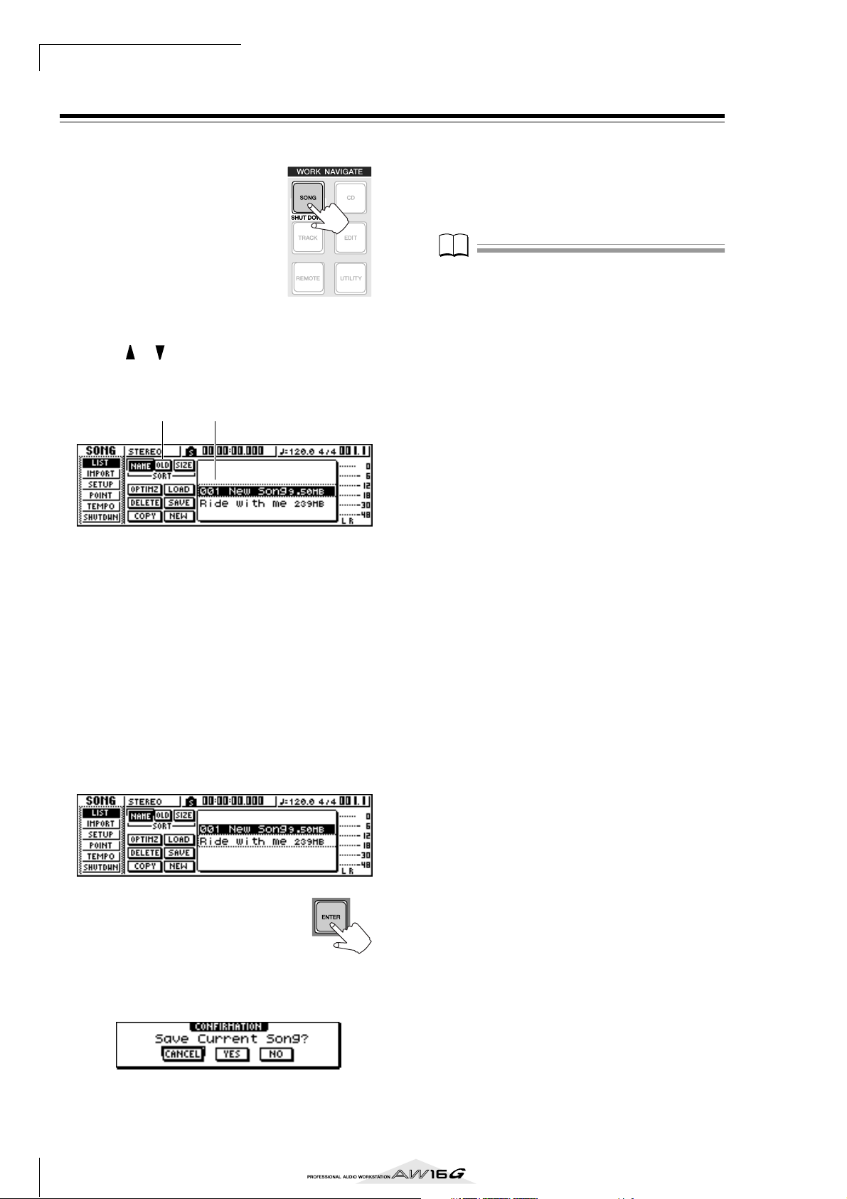
Listening to the demo song
Note
Loading the demo song
Here’s how to load the demo song from the hard disk.
In the work navigate sec-
1
tion, press the [SONG] key.
The SONG screen will appear,
where you can save or load
songs.
Either press the [SONG] key repeatedly or
2
hold down the [SONG] key and use the CURSOR [ ]/[ ] keys to access the LIST page.
In this page, you can select a song on the hard disk,
and load or delete it.
21
1 List
This area lists the songs that are saved on the hard
disk. The line enclosed by the dotted frame in the
center of the list indicates the song that is selected
for operations. The highlighted line indicates the
song that is currently loaded into the AW16G. (This
is called the “current song.”)
B SORT field
These three buttons let you select how the songs in
the list will be sorted. Choose the NAME button
(sort alphabetically), OLD button (sort by save date),
or SIZE button (sort by size).
Move the cursor to either YES (save the cur-
5
rent song) or NO (don’t save the current
song), and press the [ENTER] key.
The song data will be loaded, and “Ride with me”
will become the current song.
Note
If you select NO, any changes that you made to the current song since you last saved it will be lost.
Turn the [DATA/JOG] dial to select the song
3
“Ride with me.”
Move the cursor to the LOAD
4
button in the screen, and press
the [ENTER] key.
A popup window like the following
will appear. This window asks you
whether you want to save the current
song.
28
Page 29
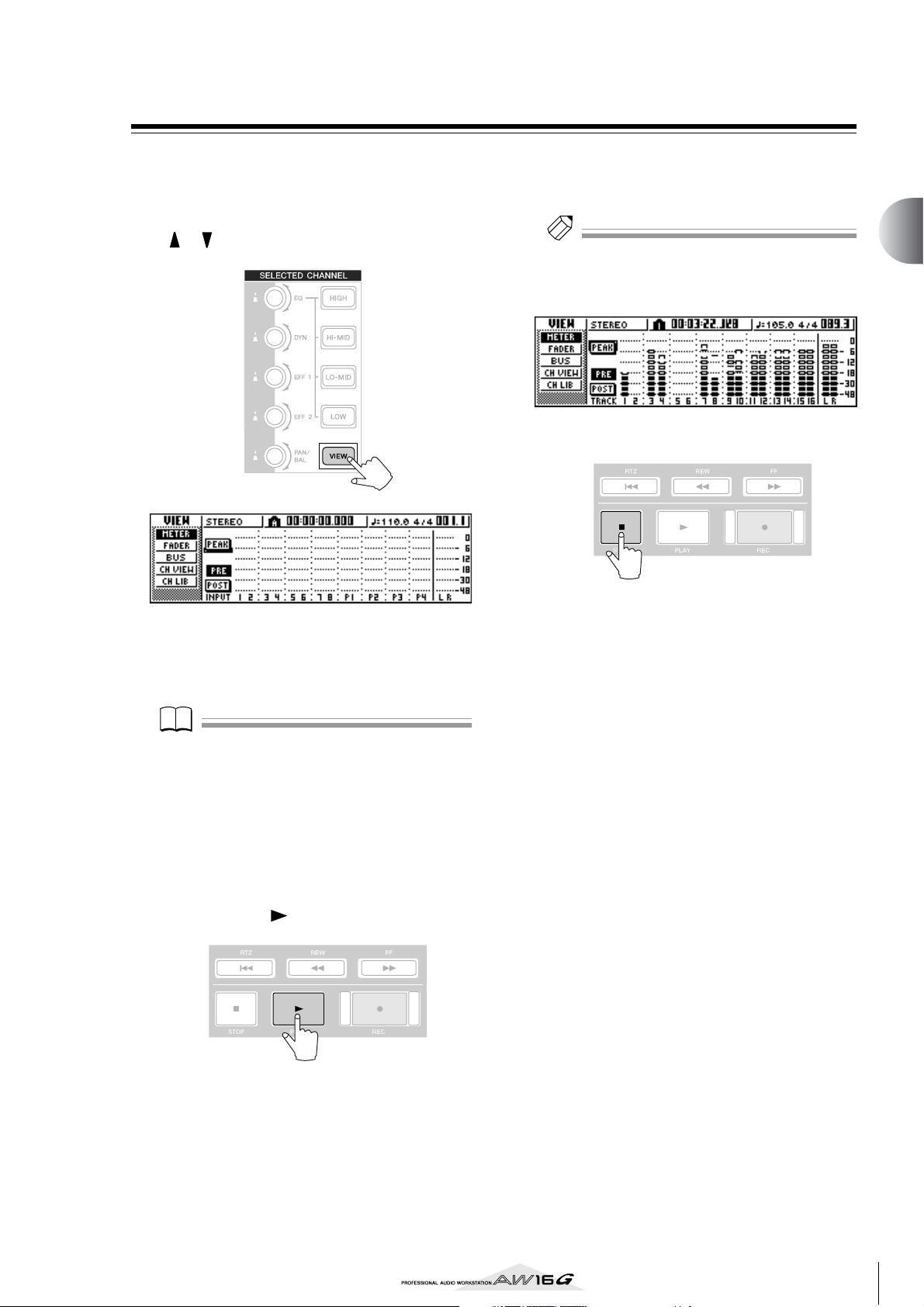
Playing the demo song
Note
Tip!
Here’s how to play back the demo song you loaded, and
adjust the monitor level.
Either press the [VIEW] key repeatedly or hold
1
down the [VIEW] key and use the CURSOR
[ ]/[ ] keys to access the VIEW screen
METER page.
To adjust the monitor level appropriately, use
4
the AW16G’s [MONITOR PHONES] knob and
the volume control of your monitor system.
Tip!
The demo song uses the Scene function to switch the settings of the mixer. This means that playback will occur
using the pre-specified balance — you do not need to
operate the faders.
To stop the song, press the STOP [■] key.
5
3
Listening to the demo song
The VIEW screen METER page contains meters that
show the input level of each channel and the output
level of the stereo output channel. It is convenient
to display this page when you want to check the
level of each track.
Note
Make sure that the selected channel area at the upper left
of the METER page indicates either TRACK 1–8 or TRACK
9/10–15/16. If neither of these are displayed, press either
the [TRACK SEL] key 1–8 or 9/10–15/16.
Lower the AW16G’s [STEREO] fader to the -
2
infinity position. Also make sure that the
AW16G’s [MONITOR PHONES] knob and the
volume of your monitor system are turned
down.
Press the PLAY [ ] key.
3
The demo song will begin playing, and the level of
each track channel will be displayed in the METER
page of the VIEW screen.
29
Page 30
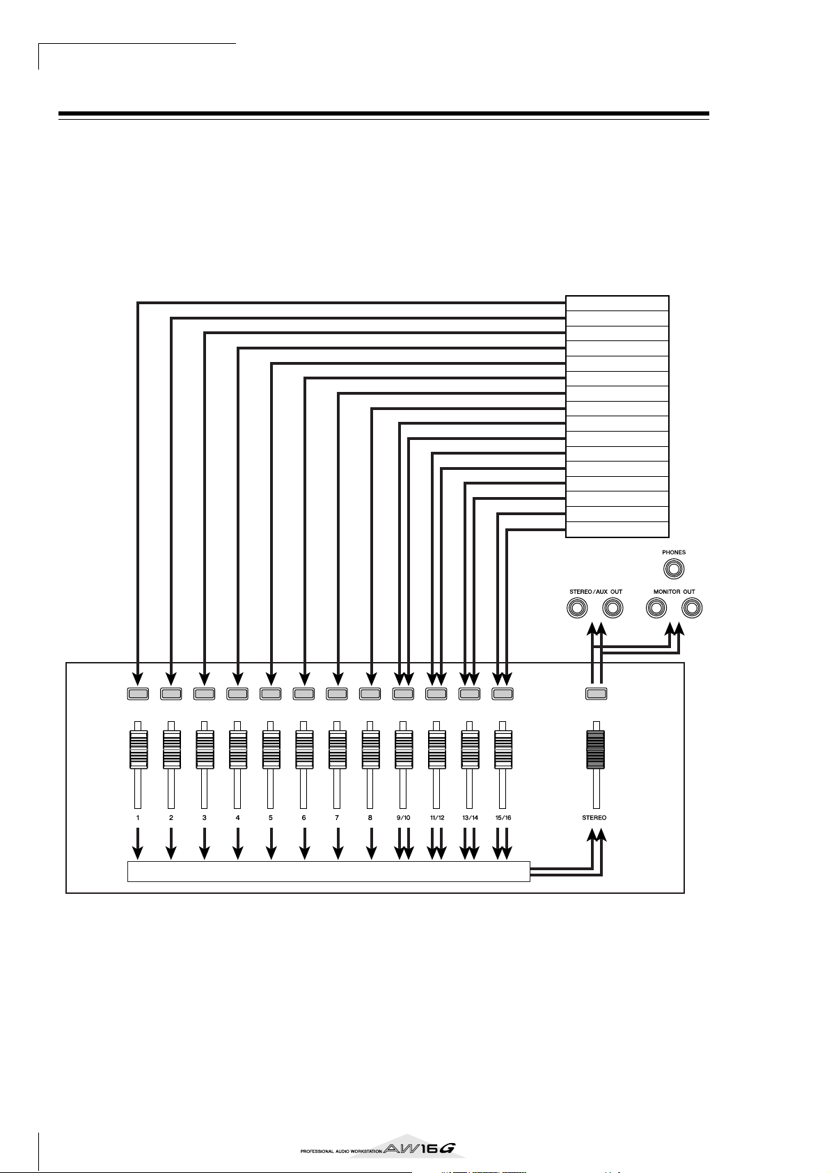
Listening to the demo song
Mixing the demo song
When you play back a song, tracks 1–16 of the recorder
are directly connected to track channels 1–8 and 9/10–
15/16 of the mixer. The signals that pass through track
channels 1–8 and 9/10–15/16 are sent to the stereo bus,
routed through the stereo output channel, and sent from
the STEREO/AUX OUT jacks or the MONITOR OUT
jacks.
● Signal flow during song playback
Recorder section
Track 1
Track 2
Track 3
Track 4
Track 5
Track 6
Track 7
Track 8
Track 9
Track 10
Track 11
Track 12
Track 13
Track 14
Track 15
Track 16
Track
channels
Stereo bus
Track channels 1–8 and 9/10–15/16 are directly controlled by the faders and [TRACK SELECT] keys of the
panel. Here’s how you can adjust the mix level of each
track channel and switch it on/off while the song plays
back.
30
Stereo output
channel
Mixer section
Page 31
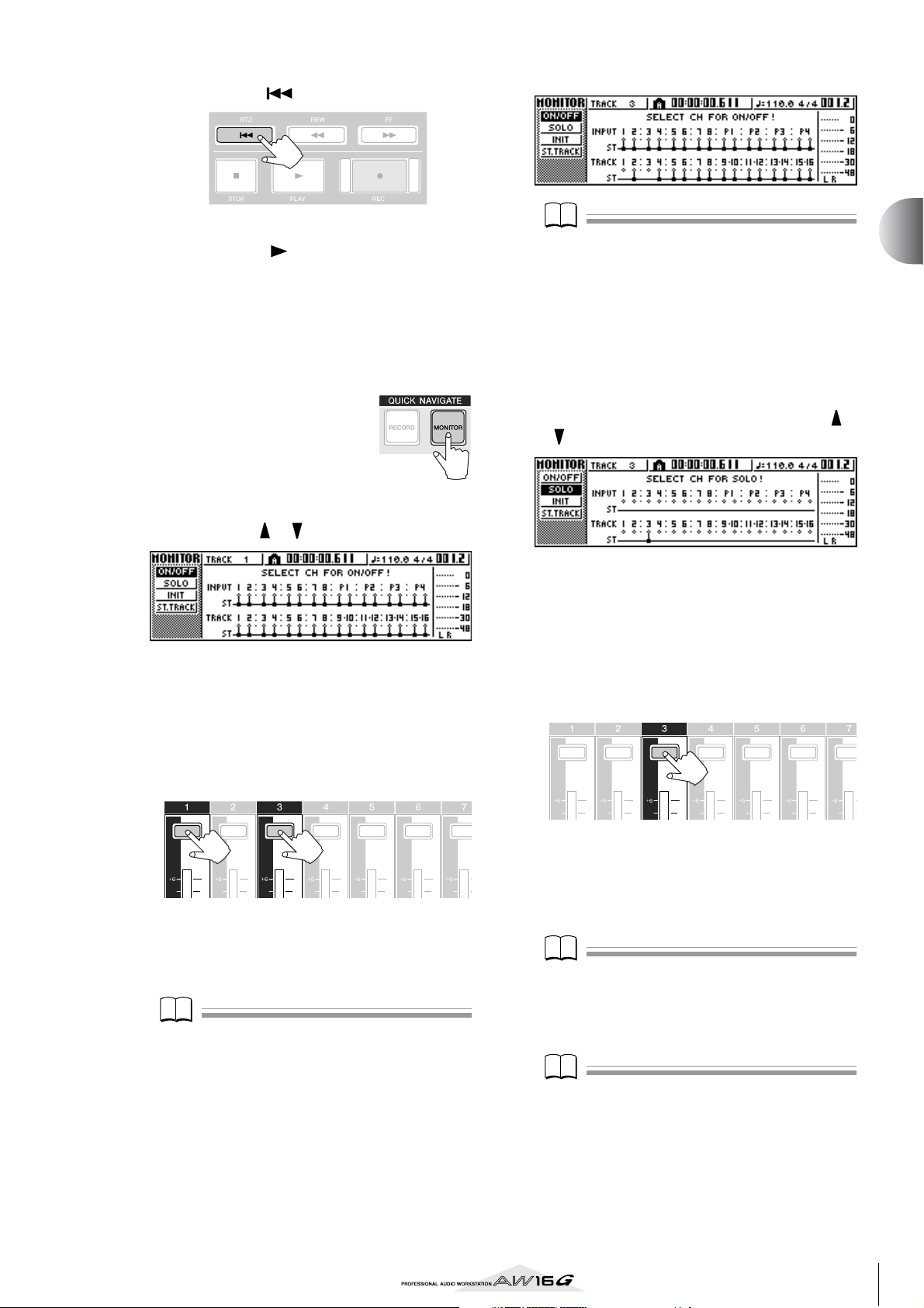
Press the RTZ [ ] key.
Note
Note
Note
Note
1
The demo song will be rewound to the beginning.
Press the PLAY [ ] button.
2
The demo song will begin playing.
While listening to the demo song, try operat-
3
ing faders 1–8 and 9/10–15/16.
Notice that the level of the corresponding track will
change. Operating the [STEREO] fader will change
the overall level of the song.
To mute the playback of a
4
specific track, access the
MONITOR screen ON/
OFF page, either by
repeatedly pressing the
[MONITOR] key or by
holding down the [MONITOR] key and using
the CURSOR [ ]/[ ] keys.
The MONITOR screen ON/OFF page lets you
switch each channel on/off. A channel that is
switched off in this page will not be sent to the stereo bus or AUX bus, and will be muted.
Note
In this page, pressing the [STEREO SEL] key will have no
effect.
To cancel the muted state, press the same
6
[TRACK SEL] key you pressed in step 5, to
make the indicator light green.
If you want to monitor the playback of just a
7
specific track, access the MONITOR screen
SOLO page by either repeatedly pressing the
[MONITOR] key or by holding down the
[MONITOR] key and using the CURSOR [ ]/
[] keys.
The SOLO page of the MONITOR screen lets you
mute all other channels while listening to only a
specific channel. (This is called the “solo” function.)
When you sol a channel in this page, the signals of
the remaining channels will be muted, and will no
longer be sent to the stereo bus or AUX buses.
Press the [TRACK SEL] key of the track chan-
8
nel that you want to solo.
3
Listening to the demo song
Press the [TRACK SEL] key(s) for the track
5
channel(s) that you want to mute. (You may
select more than one channel.)
For example if you press [TRACK SEL] keys 1 and 3,
the screen will change as follows, and track channels 1 and 3 will be muted. At this time, [TRACK
SEL] keys 1 and 3 will go dark. The graphic in the
display will also indicate this.
Note
The [TRACK SEL] key you press last will always light
orange regardless of the mute status. This indicates that
this channel is the “selected channel” (→ p. 25).
For example if you press [TRACK SEL] key 3, the
screen will change as follows, and channels other
than track channel 3 will be muted. At this time,
[TRACK SEL] key 3 will light orange, and the other
[TRACK SEL] keys and [INPUT SEL] keys will go
dark.
Note
Only one channel can be soloed at a time.
To cancel soloing, press the currently
9
selected [TRACK SEL] key (lit orange) once
again.
Note
While playing the demo song, the level or the on/off status of a channel you adjusted manually may return to its
previous setting. This is because the Scene function has
switched the state of the mixer settings, and is not a malfunction (
to temporarily prevent scenes from being recalled. (→
p. 80)
→
p. 142). You can use the Recall Safe function
31
Page 32

Listening to the demo song
32
Page 33

Chapter 4
Recording to a sound clip
The AW16G has a Sound Clip function that lets you record and play
back independently of the recorder section. You can use a sound clip
to quickly record and play back your performances on an audio
source connected to the AW16G or on the pads. This is an ideal way
to capture ideas for a song or arrangement, or to record a simple
accompaniment for practicing a part.
This chapter explains how an instrument or mic connected to an
input jack can be recorded as a sound clip.
Connecting your instrument or mic
First, the instrument or mic that you want to record must
be connected to a MIC/LINE INPUT jack. The various
types of jack are compatible with the following sources.
● MIC/LINE INPUT (XLR) jacks 1/2
These are XLR-type balanced input jacks. Use a male
XLR ↔ female XLR cable to connect your mic, direct
box, or a guitar/bass preamp that has a balanced output jack.
Balanced cable
(male XLR ↔ female XLR)
MIC/LINE INPUT
(XLR) jacks 1/2
● MIC/LINE INPUT (TRS phone) jacks 3–8
These are TRS-type balanced input jacks. Use a 1/4"
TRS phone ↔ female XLR cable to connect your mic,
direct box, or a guitar/bass preamp that has a balanced output jack.
Mic
Preamp or effect proces-
sor with balanced output
Direct box
Electric
guitar/bass
Alternatively, you can use a 1/4" phone ↔ 1/4"
phone cable to connect an instrument with unbalanced output, such as a synthesizer or rhythm
machine.
1/4" phone ↔ phone cable
MIC/LINE INPUT
(TRS phone) jacks
3–8
● MIC/LINE INPUT jack 8 (Hi-Z)
Use a 1/4" phone ↔ phone cable to directly connect
an electric guitar/bass that has passive pickups.
1/4" phone ↔ phone cable
MIC/LINE INPUT
(HI-Z) jacks 8
Synthesizer/
rhythm machine
Electric guitar/bass
with passive pickups
1/4" TRS phone ↔ female XLR
cable
Preamp or effect proces-
sor with balanced output
Direct box
MIC/LINE INPUT
(TRS phone) jacks
3–8
Mic
Electric
guitar/bass
33
Page 34

Recording to a sound clip
Note
Tip!
Adjusting the input level
The signals that are input from MIC/LINE INPUT jacks 1–
8 are sent to input channels 1–8 respectively. Here's how
to adjust the input level of the input channel, and make
settings so that you can hear the sound from your monitor system via the stereo bus.
Lower the [STEREO] fader to the –∞ position.
1
Also turn down the [GAIN] knob for the MIC/
LINE INPUT jack to which your instrument/
mic is connected.
Press and hold the [INPUT SEL] key for the
2
jack to which your instrument/mic is connected.
When you press and hold an [INPUT SEL] key, the
INPUT SETTING popup window will appear, allowing you to make settings for the corresponding input
channel. The following diagram is an example of
the screen that will appear if you press and hold
[INPUT SEL] key 1.
2
4
1 INPUT LEVEL knob
Move the cursor to this knob and turn the [DATA/
JOG] dial to adjust the level of the input channel.
Normally you will leave this at the default setting of
0 dB. The current level is shown by the value (dB
units) above the knob.
B Stereo bus assign switch
When you move the cursor to this knob and press
the [ENTER] key, the signal that is sent from the corresponding input channel to the stereo bus will be
switched on/off.
C Level meter
This indicates the input level of the input channel.
The symbol in the window indicates the location at which the level is detected.
D EXIT button
Move the cursor to this button and press the
[ENTER] key to close the popup window and return
to the previous screen.
1 3
While you watch the level meter in the
3
popup window, produce sound on your
instrument, and turn the [GAIN] knob to
adjust the input level.
As you turn the [GAIN] knob toward the right, the
level meter in the popup window will move more
widely. (However, you will not yet hear anything
from your monitor system.)
For the best audio quality, adjust the level as high as
possible without allowing the meter to clip when
the loudest volume occurs.
While you play your
4
instrument, raise the
[STEREO] fader to the
0 dB position.
The LR meters at the right
of the screen will now
move. As you turn the
[MONITOR/PHONES] knob toward the right, you
should begin to hear sound from your monitor system.
Note
If you still do not hear sound after raising the [STEREO]
fader, check the INPUT SETTING popup window to make
sure that the stereo bus assign switch is turned on, and
that the INPUT LEVEL knob value has not been set below
0.0 dB.
To exit the INPUT SETTING popup window,
5
move the cursor to the EXIT button and press
the [ENTER] key.
You will return to the previous screen.
Tip!
The level settings described above are the basic settings
for any type of recording --- not just for a sound clip. By
using the [GAIN] knob to raise the level as far as possible
without allowing distortion to occur, you can ensure that
the input signal is converted into digital form with the
highest possible quality before it is input to the mixer section. If the [GAIN] knob is not raised sufficiently, you
may not be taking full advantage of the available dynamic
range of the mixer section and recorder section. When
the input LEVEL knob and [STEREO] fader are set to the
0 dB position, the input level will be output without
change to the recorder and monitor.
34
Page 35

Recording/playing a sound clip
Now that preparations are complete, let's record to a
sound clip.
The post-fader signal of the stereo output channel can be
recorded directly on a sound clip. For playback, the signal will be sent immediately before the stereo output
channel fader. (EQ and dynamics cannot be applied to
the playback of a sound clip.)
● Signal flow when using a sound clip
SONG SCENE
REC
4
Recording to a sound clip
MUSIC
SYNTHESIZER
PRODUCTION
Sequencer
Sampling
Integrated
Real-timeExternalControl
Surface
Modular
SynthesisPlug-in
System
MIC/LINE
INPUT jacks
Input
channels
Metronome
Sound clip
Stereo output
channel
Stereo bus
Mixer section
35
Page 36
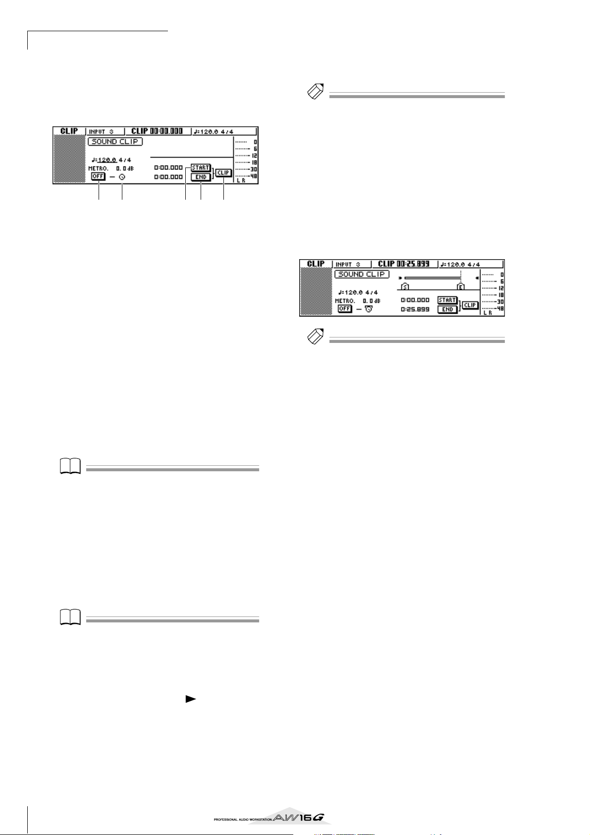
Recording to a sound clip
Note
Note
Tip!
Tip!
■ Recording a sound clip
In the Locate section, press the [SOUND
1
CLIP] key.
The CLIP screen will appear, where you can record
and play sound clips.
1 42 3 5
1 Metronome button
Switches the metronome on/off.
B Metronome knob
Adjusts the volume level of the metronome. The
value shown above the knob shows the current setting in dB units.
C START button
Specifies the current location as the start point of
the sound clip (the location at which playback will
begin). The current location is shown in minutes/
seconds/milliseconds at the left.
D END button
Specifies the current location as the end point of the
sound clip (the location at which playback will
end). The current location is shown in minutes/seconds/milliseconds at the left.
E CLIP button
When you turn this button on, the START button
(3) and END button (4) settings will be enabled.
Note
Recording and playback in the Recorder section cannot
be performed while the CLIP screen is displayed.
Play your instrument in time with the metro-
5
nome.
Tip!
• The metronome sound will not be recorded in the
sound clip. If necessary, you can move the cursor to the
metronome knob and turn the [DATA/JOG] dial to
adjust the volume level of the metronome sound.
• In addition to an instrument connected to the MIC/
LINE INPUT jacks, your performance on the quick loop
sampler pads can also be recorded.
• The knobs/keys of the selected channel are active even
while the CLIP screen is displayed. If necessary, you can
record the signal processed by EQ and dynamics (→
p. 50).
To stop recording, press the STOP [■] key.
6
The display will show S and E symbols to indicate
the start point and end point.
Tip!
•With the default settings of the AW16G, a maximum of
30 seconds can be recorded in a sound clip. If you continue recording for longer than 30 seconds, the last 30
seconds of your playing before you stopped recording
will be recorded. (However, the counter display during
recording will continue to advance.)
• In the UTILITY screen PREFER page, you can specify up
to 180 seconds as the maximum length that can be
recorded in a sound clip. You are free to make this setting before creating a new song, but this cannot be
changed once the song has been created. (
→
p. 162)
If you want to use the metronome, move the
2
cursor to the metronome button and press
the [ENTER] key.
The time signature and tempo used by the metronome are displayed above the metronome button.
To change the tempo of the metronome,
3
move the cursor to the tempo value and turn
the [DATA/JOG] dial.
Note
The time signature of the metronome is determined by
the tempo map setting immediately prior to accessing the
CLIP screen. Please be aware that the setting cannot be
edited from this screen. (For details on tempo map settings → p. 142)
In the Transport section, hold down the REC
4
[●] key and press the PLAY [ ] key.
The metronome will begin sounding, and the
counter display will advance. The counter in the
CLIP screen always starts from 0, and indicates the
current time in minutes/seconds/milliseconds. This
counter is separate from the counter of a conventional song.
36
Page 37
■ Playing a sound clip
Tip!
Note
Tip!
Note
Tip!
To hear the content that you recorded in the
1
sound clip, press the PLAY [ ] key.
The region from where you began recording to
where you stopped recording will play repeatedly.
To stop, press the STOP [■] key. If you record again,
the previous data will be overwritten.
In the CLIP screen, the keys of the Transport section
will have the following functions.
Key Function
Returns to the location at which
RTZ [ ] key
REW [ ] key
FF [ ] key
STOP [■] key
PLAY [ ] key
REC [●] key
you began recording. If the CLIP
button is on, this returns to the
Start point.
Rewinds the current location
toward the beginning. You will
stop when you reach the location
at which you began recording or
the Start point.
Fast-forwards the current location. You will stop when you reach
the location at which you stopped
recording or the End point.
Stops playback, recording, rewind,
or fast-forward.
Starts playback. Pressing this key
during playback does nothing.
If you hold down this key while
stopped and press the PLAY [ ]
key, recording will begin. Pressing
this key during playback does
nothing.
To execute the CLIP screen, press the
5
[SOUND CLIP] key.
A popup window will ask you for confirmation.
Move the cursor to the OK button to exit the CLIP
screen or to the CANCEL button to cancel, and
press the [ENTER] key.
When you exit the CLIP screen, you will return to
the TRACK screen VIEW page. However you can
press the [SOUND CLIP] key at any time to play
back the previously recorded content or record a
new performance.
Note
When you record a sound clip, the previous recording
will be lost. Please be aware that the Undo function cannot be used to recover a deleted sound clip.
Tip!
•A popup window will also ask you to confirm that you
want to exit the CLIP screen if you press a key in the
Work Navigate section or Quick Navigate section while
playback is stopped in the CLIP screen.
• The recorded contents of the sound clip are stored for
each song.
4
Recording to a sound clip
Tip!
You will not hear the metronome and pads 1–4 while a
sound clip is playing. However, you can still monitor the
signals of input channels 1–8.
If you want to change the playback region of
2
the sound clip, stop at the location that you
want to specify as the Start point, move the
cursor to the START button, and press the
[ENTER] key.
The current location will be registered as the Start
point.
In the same way, stop at the location that
3
you want to specify as the End point, move
the cursor to the END button, and press the
[ENTER] key.
Stop playback, move the cursor to the CLIP
4
button, and press the [ENTER] key.
The CLIP button will turn on, and the specified Start
point and End point will be enabled.
Note
The START button, END button, and CLIP button are disabled while the sound clip is playing.
Tip!
The region of data between the specified Start point and
End point can be copied to an audio track of the
Recorder section by using the EDIT screen COPY command (→ p. 128).
37
Page 38

Recording to a sound clip
38
Page 39

Chapter 5
Tip!
Tip!
Track recording
This chapter explains how to create a new song, and record the
audio signal from an instrument or mic connected to the AW16G
onto the first track of your song.
Creating a new song
In order to begin recording on the AW16G, you must first
create a new song.
Tip!
When you start up the AW16G for the first time, an
empty song will be loaded automatically. If you use this
automatically-loaded song, the procedure described here
is not necessary.
In the Work Navigate section, either press the
1
[SONG] key repeatedly or hold down the
[SONG] key and use the CURSOR [ ]/[ ]
keys to access the LIST page.
Move the cursor to the NEW button and
2
press the [ENTER] key.
A popup window will ask you whether you want to
save the current song.
Move the cursor to either YES (if you want to
3
save the current song) or NO (if you do not
want to save the current song), and press the
[ENTER] key.
Next, a popup window will appear, allowing you to
specify the items whose settings will be carried over
from the current song.
For example if you have saved effect settings in a
library for the current song and would like to use
these settings for the new song as well, you would
turn on the LIBRARY button.
Use the buttons to choose the items that will
4
be carried over from the current song. Then
move the cursor to the OK button and press
the [ENTER] key.
The TITLE EDIT popup window will appear, allowing you to assign a name to the song.
Assign a name to the song (for details on
5
assigning a name → p. 24).
To create the new song, move the cursor to
6
the OK button and press the [ENTER] key.
A new song will be created, and you will return to
the SONG screen LIST page.
Tip!
• If you move the cursor to the CANCEL button (instead
of the OK button) and press the [ENTER] key, you will
return to the SONG screen LIST page without creating
a new song.
•You may also edit the song name later (→ p. 138).
You may choose one or more of the following items
if desired.
SCENE button ............ Scene memories
LIBRARY button......... EQ, dynamics, effects, and channel
libraries
TEMPO button ........... Tempo map
39
Page 40

Track recording
Direct recording and Bus recording
Instruments/mics connected to the AW16G can be
assigned to tracks in one of the following two ways.
■ Direct recording
With this method, input channels are assigned to
tracks in a one-to-one correspondence. This method
requires the same number of tracks as the number of
input channels you use. However, this method has
the advantage that you will be free to adjust the volume, pan (stereo position), and tone of each instrument after it has been recorded.
Synthesizer/
rhythm machine
Recorder section
Track 1
Track 2
Track 3
Track 4
Track 5
Track 6
Track 7
Track 8
MIC/LINE
INPUT jacks
Input
channels
Stereo output
channel
Mixer section
40
Page 41

■ Bus recording
Note
With this method, you can send multiple input channels to the L/R bus, and assign the mixed signal to
one or two tracks. This method requires fewer tracks.
However, you will need to decide on the final volume, pan, and tone of each instrument at the time of
recording. (You will not be able to adjust these independently after recording.)
MIC/LINE
INPUT jacks
Synthesizer/
rhythm machine
5
Track recording
Input
channels
Recorder section
Track 1
Track 2
Track 3
Track 4
Track 5
Track 6
Track 7
Track 8
Note
The way in which you assign the input signals to tracks
will depend on the method you choose.
Stereo output
channel
L/R bus
Mixer section
41
Page 42

Track recording
Tip!
Assigning input signals to tracks
(Direct recording)
Lower the [STEREO] fader to the –∞ position.
1
Connect instruments/mics to MIC/LINE
2
INPUT jacks 1–8.
In the Quick Navigate sec-
3
tion, either press the
[RECORD] key repeatedly or
hold down the [RECORD]
key and use the CURSOR
[ ]/[ ] keys to access the
DIRECT page of the RECORD screen.
The [INPUT SEL] keys and [TRACK SEL] keys will
blink red.
The screen will indicate how input channels are
connected to tracks.
C 1-8 button
If you move the cursor to this button and press the
[ENTER] key, input channels 1–8 will be connected
to tracks 1–8.
D 9-16 button
If you move the cursor to this button and press the
[ENTER] key, input channels 1–8 will be connected
to tracks 9–16.
E SAFE button
If you move the cursor to this button and press the
[ENTER] key, all connections will be cancelled.
Press the [INPUT SEL] key for the input chan-
4
nel to which your instrument/mic is connected.
The corresponding [INPUT SEL] key will light red,
and the remaining [INPUT SEL] keys will go dark. If
this input channel is not yet assigned to a track, all
[TRACK SEL] keys will blink red. This blinking indicates that the tracks can be selected as the recording destination.
1
2
543
1 INPUT
Indicates the connection status of input channels 1–
8.
If you move the cursor to numbers 1–8 and press
the [ENTER] key, the INPUT SETTING popup window will appear, allowing you to make settings for
the corresponding input channel.
If you move the cursor to the symbol and press
the [ENTER] key, the symbol will be highlighted,
and the corresponding input channel will be
selected as a recording source.
B TRACK
Indicates the connection status of tracks 1–16.
If you move the cursor to the symbol and press
the [ENTER] key, the symbol will be highlighted,
and the corresponding track will be selected as a
recording destination.
In the screen, the symbol
for that input channel will be
highlighted.
Tip!
•You can also select an input channel by moving the cursor to the symbol of the desired input channel and
pressing the [ENTER] key.
• If you select an input channel to which a track is
already assigned, only the corresponding [TRACK SEL]
key will blink red.
• If you press and hold the [INPUT SEL] key of an input
channel, the INPUT SETTING popup window will
appear, allowing you to make settings for the corresponding input channel. To exit this window and return
to the previous screen, move the cursor to the EXIT button and press the [ENTER] key.
42
Page 43
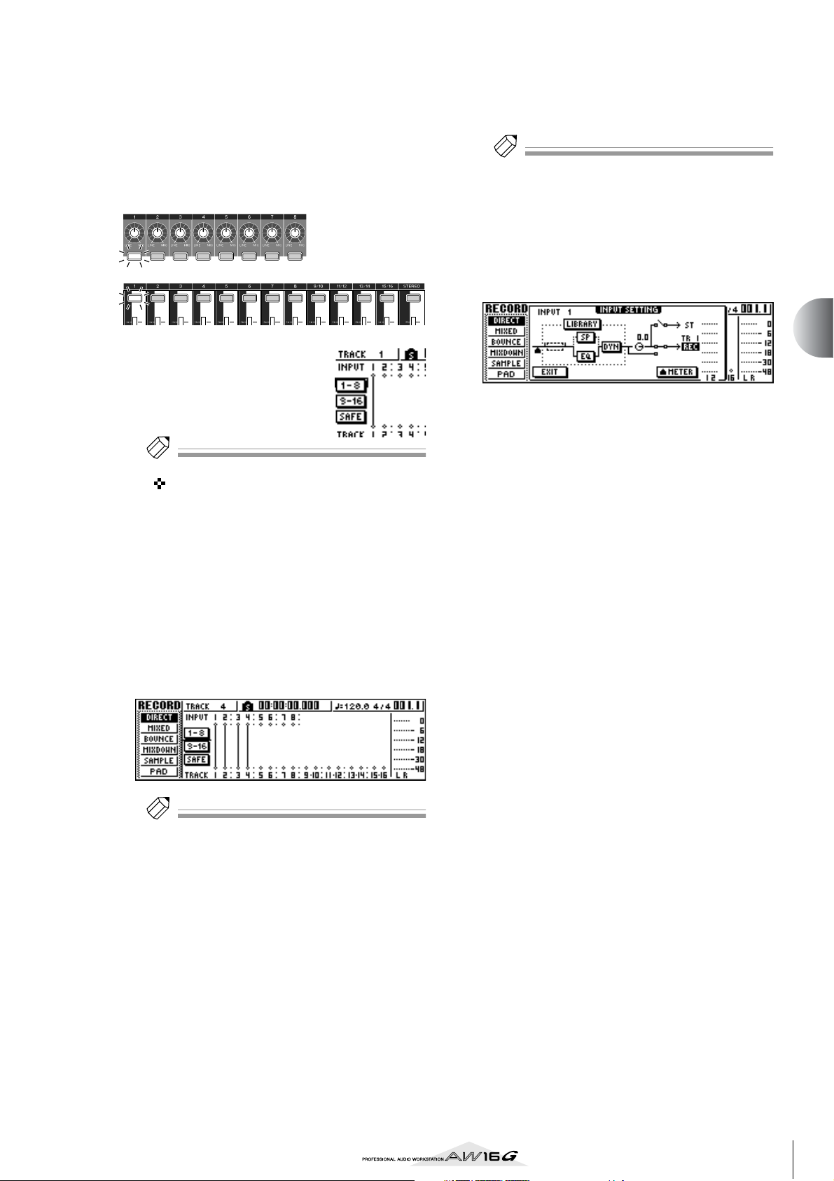
Press the [TRACK SEL] key of the track on
Tip!
Tip!
Tip!
5
which you want to record.
The selected input channel and track will be connected internally. At this time, only the selected
[INPUT SEL] key and [TRACK SEL] key will be
blinking red. The blinking [TRACK SEL] key indicates that the corresponding track is in record-ready
mode.
Press and hold the [INPUT SEL] key for the
7
recording-source input channel, to access the
INPUT SETTING popup window.
Tip!
You can also access the INPUT SETTING popup window
by moving the cursor to an input channel number in the
RECORD screen DIRECT page, and pressing the [ENTER]
key.
Use the [GAIN] knob to adjust the input level
8
of the signal.
For details on adjusting the input level, refer to
“Recording to a sound clip” (→ p. 33).
In the screen, a line will be
drawn to indicate the connection.
Tip!
•You can also select a track by moving the cursor to the
symbol of the desired track and pressing the
[ENTER] key.
• The input channel and track will be internally con-
nected even if you first press the [TRACK SEL] key and
then press the [INPUT SEL] key afterward.
•When an input channel is selected as a recording
source, its assignment to the stereo bus will automatically be turned off, and it will be connected to allow
monitoring via the track channel.
•EQ and dynamics settings will be flat for a track chan-
nel that is selected as the recording destination.
If you want to record more than one instru-
6
ment or mic simultaneously, assign other
input channels to tracks in the same way.
Tip!
•To cancel a connection that you made, press the
[INPUT SEL] key to make it light red, and then press the
[TRACK SEL] key of the track that is selected as the
recording destination. To cancel all connections, move
the cursor to the SAFE button and press the [ENTER]
key.
•To change the recording destination, press the [INPUT
SEL] key to make it light red, and then press the [TRACK
SEL] key of a different track.
• If both the recording-source inputs and the recording-
destination tracks are paired, two adjacent odd-numbered/even-numbered channels will be simultaneously
assigned to two adjacent odd-numbered/even-numbered tracks.
If an input channel is connected to a recording-destination, that recording-destination and the METER
button will be added to the display in the INPUT
SETTING popup window.
By moving the cursor to the METER button and
pressing the [ENTER] key, you can switch the location at which the level is detected between “prefader” (default setting; immediately after A/D) and
“post-fader” (after the signal has passed through EQ,
dynamics, and the level knob). Check that the
increase in level after passing through EQ and
dynamics does not cause the signal to clip.
Raise the [STEREO] fader to the 0 dB position.
9
To monitor the signal that you are recording,
10
raise the fader of the track channel that you
selected as the recording destination.
Normally when recording, you do not monitor the
input channel signal before it is recorded, but rather
the signal after passing through the recorder, via the
track channel. This lets you monitor the signal that
is actually being recorded, and also lets you adjust
the volume and tone of the monitor signal without
affecting the signal that is being recorded.
If the track channel fader for the recording-destination track is set to the 0 dB position, the monitor
level during recording will be the same as the playback level after recording.
5
Track recording
43
Page 44

Track recording
Note
● Monitor signal flow during recording
Recorder section
Track 1
Track 2
Track 3
Track 4
Track 5
Track 6
Track 7
Track 8
from the input
channels
Track
channels
To adjust the pan of the
11
monitor signal, press the
[TRACK SEL] key for the
corresponding track
channel, and turn the
[PAN/BAL] knob of the
Selected Channel section.
Stereo output channel
Stereo bus
Mixer section
Note
The pan setting of an input channel will have no effect if
that input channel is assigned to a track by direct recording.
44
Page 45

Assigning input signals to tracks
Tip!
Tip!
(Bus recording)
Lower the [STEREO] fader to the –∞ position.
1
Connect instruments/mics to MIC/LINE
2
INPUT jacks 1–8.
In the Quick Navigate section, either press
3
the [RECORD] key repeatedly or hold down
the [RECORD] key and use the CURSOR [ ]/
[] keys to access the MIXED page of the
RECORD screen.
In the MIXED page of the RECORD screen, you can
assign the input channel signals to any one or two
tracks via the L/R bus.
1 2
3
45
1 INPUT
Selects the record-source input channel.
B L/R bus
The two horizontal lines indicate the bus L/R signal
route. You can check the on/off status of the signal
that is sent from the record-source input channel(s)
to bus L or R, and check the tracks that will be the
record-destination of the L/R bus.
C TRACK
Selects the track(s) that will be the record-destination of the L/R bus signal.
D SAFE button
To cancel all record-sources and record-destinations, move the cursor to this button and press the
[ENTER] key.
E BUS button
When you move the cursor to this button and press
the [ENTER] key, a dedicated fader and level meter
for the L/R bus will appear in the right of the screen.
You can use this to adjust the master level of the L/R
bus.
The current setting [INPUT SEL] key will light
orange, and that input channel will be selected for
operations.
In the screen, the symbol
for the corresponding input
channel will be highlighted,
and a line will appear, indicating that this channel is connected to the bus.
Tip!
•You can also select an input channel by moving the cursor to the symbol for the desired input channel and
pressing the [ENTER] key.
• If you press and hold the [INPUT SEL] key of an input
channel, the INPUT SETTING popup window will
appear, allowing you to make settings for the corresponding input channel. To close this popup window
and return to the previous screen, move the cursor to
the EXIT button and press the [ENTER] key.
Repeatedly press the same
5
[INPUT SEL] key as in step
4, and the signal sent
from that input channel to
the L/R bus will be
switched on/off.
Each time you press the
[INPUT SEL] key, the screen
will change as follows.
5
Track recording
Press the [INPUT SEL] key for the input chan-
4
nel to which you connected your instrument
or mic.
Tip!
For an input channel that is selected as a record-source,
the assignment to the stereo bus will automatically be
turned off, and connections will be made so that the signal can be monitored via the track channel.
45
Page 46

Track recording
Tip!
Note
Tip!
As necessary, use the same procedure to
6
specify other input channels as recordingsources.
Press the [TRACK SEL] key(s) for the record-
7
destination track(s).
You can select up to two tracks as the record-destination.
If you select track 1, 3, 5, or 7, the signal will be
connected to bus L. If you select track 2, 4, 6, or 8,
the signal will be connected to bus R. If you select
tracks 9/10–15/16, odd-numbered tracks will be
connected to bus L, and even-numbered tracks will
be connected to bus R.
The screen will display lines to indicate how the
signals are connected to the track(s).
Tip!
•EQ and dynamics settings will be flat for a track channel whose track has been selected as a record-destination.
• If a single track is selected, the pan of the track channel
will be centered. If a paired track (→ p. 49) is selected,
the odd-numbered/even-numbered track channels will
be panned to left and right respectively.
• The connection will be cancelled if you once again
press the [TRACK SEL] key of a currently selected track.
For each input channel to which you con-
8
nected an instrument or mic, press and hold
the [INPUT SEL] key to access the INPUT SETTING popup window, and use the [GAIN]
knob to adjust the input level of the signal.
For details on adjusting the input level, refer to
“Recording to a sound clip” (→ p. 33).
To adjust the volume balance of each input
12
channel, repeatedly press the [VIEW] key in
the Selected Channel section to access the
FADER page.
When you want to set the volume balance of the
input channels, it is convenient to use the FADER
page of the VIEW screen. Here you can adjust the
on/off status and input levels for the input channels,
pad channels, and track channels — all in one
page.
While producing sound on your instruments,
13
use the [INPUT SEL] keys or CURSOR [ ]/
[] keys to move the cursor to the input
channel that you want to control, and turn
the [DATA/JOG] dial to adjust the volume
balance.
Note
We recommend that you not use the [GAIN] knob to
adjust the volume balance of the input channels. This will
degrade the S/N ratio, and may cause the sound to distort.
Tip!
•You can also use the INPUT LEVEL knob in the INPUT
SETTING popup window to adjust the volume balance
of the input channels.
• Normally, the panel faders are dedicated to the track
channels. However by changing an internal setting, you
can use the faders to control the input levels of the
input channels. (→ p. 162)
Raise the [STEREO] fader to the 0 dB position.
9
Raise the track channel fader for the record-
10
destination track, so that the monitor level is
appropriate.
Now you will be able to monitor the signal that is
being sent to the track(s) via the L/R bus.
To set the pan of each input channel, use the
11
[INPUT SEL] key to select a channel, and turn
the [PAN/BAL] knob of the Selected Channel
section.
When you use bus recording, it will not be possible
to adjust the pan or volume balance for individual
instruments after they have been recorded on the
track(s). This means that you must finalize the pan
and volume balance when you send the signals
from the input channels to the L/R bus.
46
Page 47

Enabling the metronome
Tip!
Before you begin recording, set the tempo and volume of
the metronome. If you will not be using the metronome
while recording, you can skip the following procedure.
In the Work Navigate section, repeatedly
1
press the [TRACK] key or hold down the
[TRACK] key and use the CURSOR [ ]/[ ]
keys to access the VIEW page.
1 2
1 Metronome button
Switches the metronome on/off.
B Metronome knob
Adjusts the metronome volume level. The current
value is shown above the knob in dB units.
Move the cursor to the metronome button
2
and press the [ENTER] key.
The metronome will be turned on.
Move the cursor to the TEMPO field of the
5
event, and turn the [DATA/JOG] dial to set
the tempo value.
You can set a tempo in a range of 30–250 (BPM).
If necessary, move the cursor to the METER
6
field and turn the [DATA/JOG] dial to change
the time signature.
You can set a time signature in a range of 1/4–8/4.
Tip!
• It is also possible to change the tempo or time signature
during a song. For details, refer to “Song management”
(→ p. 137).
• It is also possible to use the Quick Loop Sampler as a
rhythm machine, instead of the metronome. For details,
refer to “Using sample libraries” (→ p. 109).
5
Track recording
When you press the [PLAY] key to begin play-
3
back, the metronome will begin sounding. As
necessary, move the cursor to the metronome knob and turn the [DATA/JOG] dial to
adjust the metronome level.
If you want to change the tempo or time signature,
press the [STOP] key to stop playback, and perform
the following procedure.
In the Work Navigate section, repeatedly
4
press the [SONG] key or hold down the
[SONG] key and use the CURSOR [ ]/[ ]
keys to access the TEMPO page.
The TEMPO page lets you create a tempo map that
specifies the tempo and time signature of the song.
The tempo and time signature that you specify here
will be the basis for the measure/beat display
counter, the internal metronome, and the MIDI
clock messages generated by the AW16G.
1
1 Tempo map events
These are the events recorded in the tempo map.
When you create a new song, a tempo map event of
time signature = 4/4 and tempo = 120 will be created at the beginning of the song (measure 1, beat
1).
47
Page 48

Track recording
Note
Recording on a track
Now that you have completed your preparations, let’s
record on a track.
In the Work Navigate section, repeatedly
1
press the [TRACK] key or hold down the
[TRACK] key and use the CURSOR [ ]/[ ]
keys to access the VIEW screen.
2 3
5 6
4
1 Track view
Graphically indicates the presence of data and
markers in tracks 1–16, pad tracks 1–4, and the stereo track.
B TRACK field
Selects the track that you want to operate in the
screen. You can select 1–16 (audio track 1–16), ST
(stereo track), or PAD 1–4 (pad track 1–4).
Note
Changing the track here will not change the track to be
recorded.
C V.TR field
If you selected 1–16 or ST in the TRACK field, this
area will indicate the number of the currently
selected virtual track.
D Track name
Displays the name that has been assigned to the virtual track. If nothing has been recorded, a name of
“-NO REC-” will be assigned.
E WAVE button
When you move the cursor to this button and press
the [ENTER] key, the waveform of the currently
selected track will be displayed. This button will
appear only if you have selected 1–16 or ST in the
TRACK field.
F NAME button
When you move the cursor to this button and press
the [ENTER] key, the TITLE EDIT popup window
will appear, allowing you to assign a name to the
track.
1
Play your instrument in time with the metro-
3
nome.
The metronome sound will not be recorded on the
track. If necessary, move the cursor to the metronome knob and turn the [DATA/JOG] dial to adjust
the metronome volume level.
To stop recording, press the STOP [■] key.
4
I (In point) and O (Out point) symbols will appear in
the track view of the VIEW page, indicating the
location of the most recent recording operation.
The [UNDO/REDO] key of the data entry/control
section will light. This indicates that you can press
the [UNDO/REDO] key to execute the Undo function.
To hear the recorded content from the
5
beginning, press the RTZ [ ] key to return
the counter display to zero, and press the
PLAY [ ] key.
If you want to redo the recording, press the
6
[UNDO/REDO] key.
The [UNDO/REDO] key will go dark, and you will
return to the state prior to recording. Repeat steps
2–5.
When you finish recording, press the Quick
7
Navigate Section [RECORD] key once again,
move the cursor to the SAFE button, and
press the [ENTER] key.
A popup window will ask you for confirmation, so
move the cursor to the OK button and press the
[ENTER] key. Assignments of the input signals to
tracks will be cancelled. It will no longer be possible to press the [REC] key, and this will prevent
recording from occurring accidentally.
If you are satisfied with the recorded content,
8
save the song. (For details on saving → p. 63)
Please be aware that the recorded content will be
lost if you turn off the power of the AW16G before
saving the song.
In the Transport section, hold down the REC
2
[●] key and press the PLAY [ ] key.
The metronome will begin sounding, and the
counter display will advance.
In the track view within the screen, the vertical line
that indicates the current location will advance
toward the right.
48
Page 49
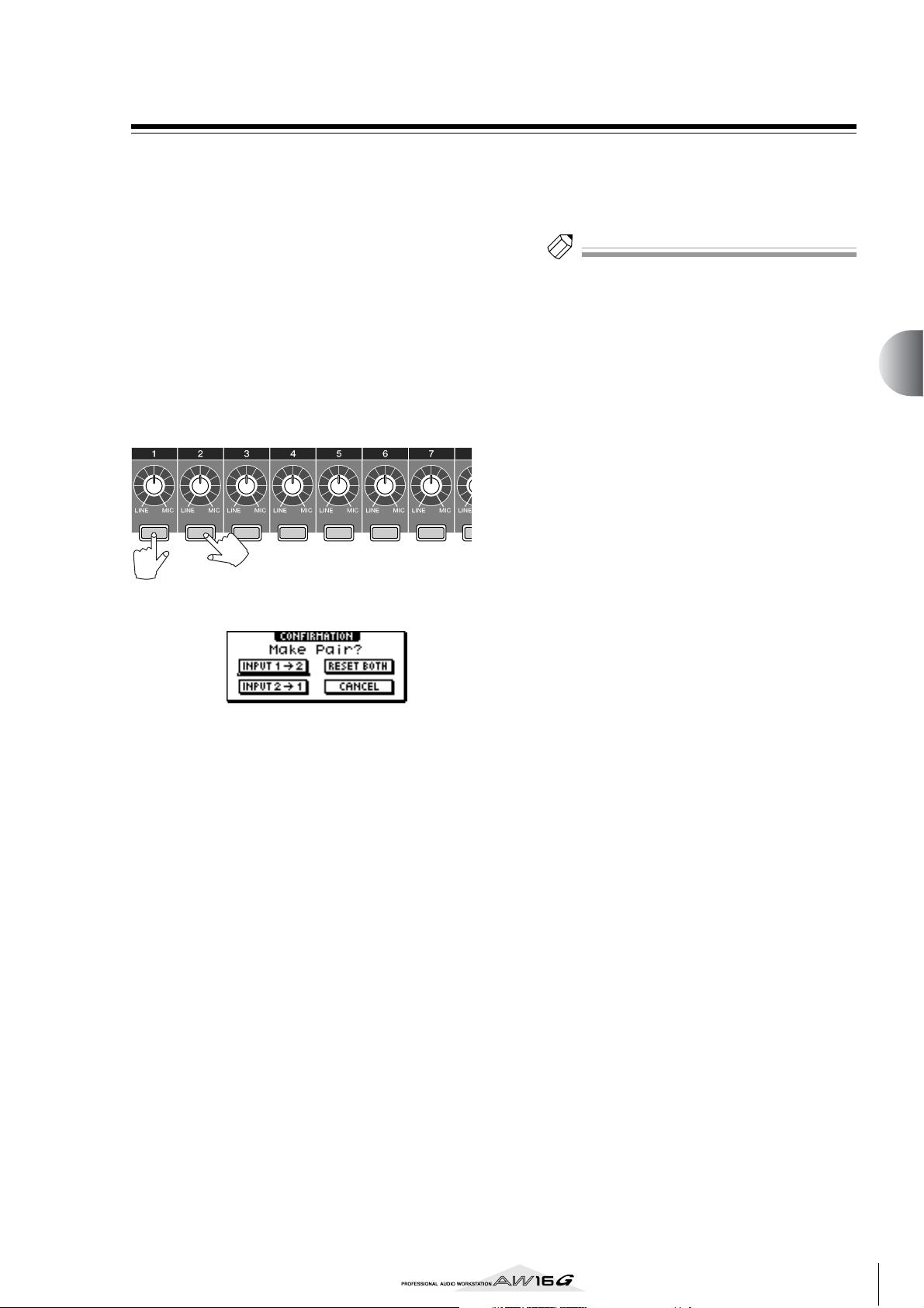
Pairing input channels/track channels
Tip!
Pad tracks 1–4 and track channels 9/10–15/16 are permanently paired.
However, you may also specify pairing for adjacent oddnumbered/even-numbered input channels (1/2, 3/4, 5/6,
7/8) or track channels (1/2, 3/4, 5/6, 7/8). When two
channels are paired, most of their parameters will be
linked, so that operating one of the channels will cause
the same setting to occur on the other channel as well.
This is convenient when you are recording a stereo audio
source, or when you want to play back two bus-recorded
tracks as a single stereo track.
Hold down the [INPUT SEL] key (or [TRACK
1
SEL] key) of one channel that you want to
pair, and then press the other [INPUT SEL]
key (or [TRACK SEL] key).
A popup window will appear, asking you to confirm
the pairing.
To cancel pairing, press the OK button. If you
4
decide not to cancel pairing, move the cursor
to the CANCEL button and press the [ENTER]
key.
Tip!
In the case of paired channels, setting the pan to far left
or far right will produce nominal level. (The levels before
and after passing through Pan will be the same.) In the
case of paired channels, setting the pan to center will
produce nominal level.
5
Track recording
Move the cursor to one of the following but-
2
tons and press the [ENTER] key.
INPUT (TRACK) x → y (x= odd number,
y= even number)........ Copy the settings of input (track)
channel x to y, and pair them.
INPUT (TRACK) y → x (x= odd number,
y= even number)........ Copy the settings of input (track)
channel y to x, and pair them.
RESET BOTH.............. Initialize both input (track) chan-
nels, and pair them.
CANCEL..................... Cancel pairing.
When input channels are paired, all mix parameters
other than the [GAIN] knob and phase/pan settings
will be linked.
When track channels are paired, all mix parameters
other than the phase/pan settings will be paired.
Operating just the odd-numbered fader will adjust
the level of both odd-numbered/even-numbered
channels. (While channels are paired, the evennumbered fader has no effect.)
To defeat pairing, hold down the [INPUT SEL]
3
key (or [TRACK SEL] key) of one of the channels, and press the other [INPUT SEL] key (or
[TRACK SEL] key).
A popup window will ask you to confirm that you
want to cancel pairing.
49
Page 50

Track recording
Note
Note
Using the input library
The input library is a library of settings used to apply
internal effects, EQ, or dynamics settings to the input signal when you want to record the processed signal. Here’s
how to apply input library settings to the signal of an
input channel.
Press and hold the [INPUT SEL] key of the
1
input channel for which you want to use the
input library. The INPUT SETTING popup
window will appear.
Move the cursor to the LIBRARY button, and
2
press the [ENTER] key.
The following popup window will appear.
In this popup window, you can select whether the
internal effect 1 or 2 will be patched to the input
channel.
Note
When you use the input library, internal effect 1 or 2 will
be disconnected from the send/return of the mixer, and
patched to a specific input channel. For this reason, you
can use the internal effects on a maximum of two channels.
Turn the [DATA/JOG] dial to select the
4
desired input library data.
The input library data is organized into the following categories.
Number Abbreviation Category
00
01–25
26–30
31–35 BA Data suitable for bass.
36–40 VO Data suitable for vocals
EG Data suitable for electric
AG Data suitable for acoustic
Data for initializing the
input channel
guitar.
guitar.
Note
All input library data is read-only.
Select the desired data, and press the
5
[ENTER] key.
A popup window will ask you to confirm the recall
operation.
Move the cursor to the OK button and press
6
the [ENTER] key.
The data of the selected library will be loaded, and
the internal effect, EQ (or speaker simulator), and
dynamics effect will be applied to the input signal.
Move the cursor to the EFF1 button or EFF2
3
button, and press the [ENTER] key.
The INPUT LIBRARY popup window will appear,
allowing you to select an input library.
1
2
3
1 List
This is the library list. The line surrounded by a dotted line in the middle of the list is the data that is
selected for loading. When you turn the [DATA/
JOG] dial, the data in the list will scroll upward or
downward.
B RECALL button
Move the cursor to this button and press the
[ENTER] key to load the currently selected data.
C EXIT button
Move the cursor to this button and press the
[ENTER] key to close the popup window.
50
Page 51
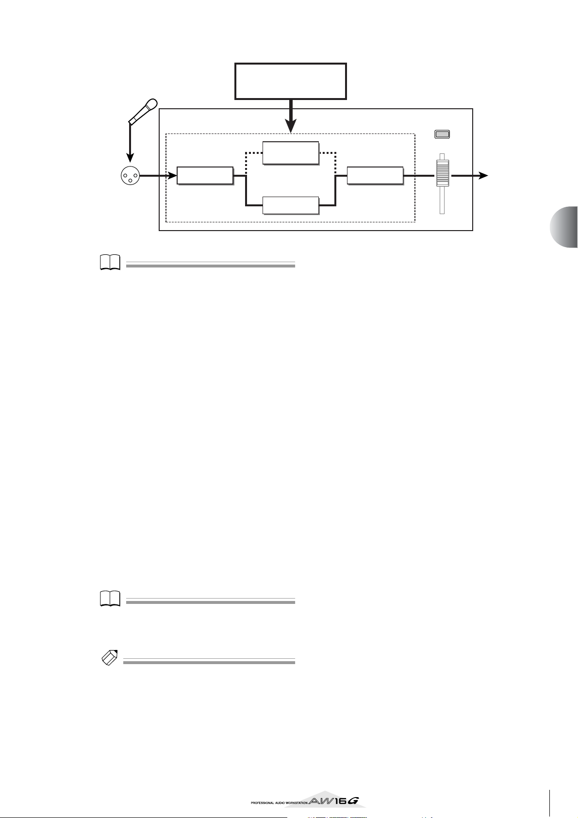
Note
Note
Tip!
MIC/LINE
INPUT jack
Input library
Speaker
simulator
Internal effect
Note
If the input channel is paired, the same settings will be
applied to both channels.
If you want to adjust the effect, use the
7
[INPUT SEL] key to select the input channel.
While you produce sound on your instrument, adjust the [EQ] knob, [DYN] knob, or
[EFF 1]/[EFF 2] knobs of the Selected Channel
section.
Immediately after you select an input library, turning the knobs of the Selected Channel section will
control the following items.
Turning the [EQ] knob ......Adjusts the amount of boost/
cut for each EQ band. To select
the band that will be adjusted,
use the [HIGH] key, [HI-MID]
key, [LO-MID] key, or [LOW]
key located at the right.
Turning the [DYN] knob....Simultaneously adjusts multi-
ple dynamics parameters to
adjust the dynamics effect. The
result will depend on the
library that you selected.
Turning the [EFF 1] knob...Adjusts the balance of direct
sound and processed sound
for internal effect 1.
Turning the [EFF 2] knob...Adjusts the balance of direct
sound and processed sound
for internal effect 2.
EQ
Input channel
Dynamics
to the bus
INPUT LEVEL
5
Track recording
Note
Depending on the input library you select, the level of
the input channel may change. Re-adjust the volume balance using the INPUT LEVEL knob in the INPUT SETTING popup window.
Tip!
If turning the [EQ] knob or [DYN] knob does not produce
the desired result, you can reload new settings from the
EQ library or dynamics library (→ p. 77, 78).
In the same way, select input library settings
8
for the other input channels.
However, a maximum of two input channels can
use the internal effects at the same time.
51
Page 52
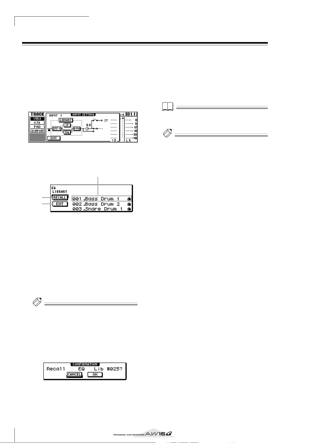
Track recording
Tip!
Note
Tip!
Using the EQ library
The EQ library contains EQ settings appropriate for a
variety of instruments. Use these when you want to apply
EQ to an input channel while you record, or when you
want to modify the EQ settings after recalling an input
library.
Press and hold the [INPUT SEL] key of the
1
input channel for which you want to use the
input library, to access the INPUT SETTING
popup window.
Move the cursor to the EQ button in the
2
screen, and press the [ENTER] key.
The EQ library will appear.
1
2
3
Move the cursor to the EXIT button and press
5
the [ENTER] key.
If you want to adjust the EQ settings, press
6
the [HIGH] key, [HI-MID] key, [LO-MID] key,
or [LOW] key of the Selected Channel section
to select the band, and turn the EQ knob to
adjust the amount of boost/cut.
Note
If turning the EQ knob does not change the tone, check
whether EQ may have been turned off for that channel
(→ p. 92).
Tip!
If necessary, you can also adjust the frequency and Q
parameters of each band. For details, refer to “Using
libraries and scene memories” (→ p. 73).
1 List
This is the library list. The line surrounded by a dotted line in the middle of the list is the data that is
selected for loading. When you turn the [DATA/
JOG] dial, the data in the list will scroll upward or
downward.
B RECALL button
Move the cursor to this button and press the
[ENTER] key to load the currently selected data.
C EXIT button
Move the cursor to this button and press the
[ENTER] key to close the popup window.
Tip!
You can also access the EQ library by pressing the [EQ]
knob of the Selected Channel section. For details, refer to
“Using libraries and scene memories” (→ p. 73).
Turn the [DATA/JOG] dial to select the library
3
that you want to use, and press the [ENTER]
key.
A popup window will ask you to confirm the library
recall operation.
Move the cursor to the OK button and press
4
the [ENTER] key.
The selected library will be loaded.
52
Page 53

Using the dynamics library
Tip!
Note
Tip!
The dynamics library contains dynamics settings suitable
for a variety of instruments. As for the EQ library, you can
use this to apply dynamics processing to an input channel while you record, or when you want to modify the
dynamics settings after recalling an input library.
Press and hold the [INPUT SEL] key of the
1
input channel for which you want to use the
dynamics library, to access the INPUT SETTING popup window.
Move the cursor to the DYN button in the
2
screen, and press the [ENTER] key.
The dynamics library will appear.
1
2
3
Move the cursor to the EXIT button and press
5
the [ENTER] key.
If you want to adjust the dynamics settings,
6
turn the [DYN] knob of the Selected Channel
section.
Turning the [DYN] knob immediately after a library
has been recalled will simultaneously adjust multiple dynamics parameters to control the dynamics
effect. (The result will depend on the library that
you select.)
Note
If turning the [DYN] knob does not change the tone,
check whether dynamics may have been turned off for
that channel (→ p. 93).
Tip!
If necessary, you can also make detailed adjustments to
the individual dynamics parameters. For details, refer to
“Using libraries and scene memories” (→ p. 73).
5
Track recording
1 List
This is the library list. The line surrounded by a dotted line in the middle of the list is the data that is
selected for loading. When you turn the [DATA/
JOG] dial, the data in the list will scroll upward or
downward.
B RECALL button
Move the cursor to this button and press the
[ENTER] key to load the currently selected data.
C EXIT button
Move the cursor to this button and press the
[ENTER] key to close the popup window.
Tip!
You can also access the dynamics library by pressing the
[DYN] knob of the Selected Channel section. For details,
refer to “Using libraries and scene memories” (→ p. 73).
Turn the [DATA/JOG] dial to select the library
3
that you want to use, and press the [ENTER]
key.
A popup window will ask you to confirm the library
recall operation.
Move the cursor to the OK button and press
4
the [ENTER] key.
The selected dynamics library will be loaded.
53
Page 54

Track recording
54
Page 55

This chapter explains how you can record additional performances
on other tracks while you listen to the previously-recorded tracks.
This chapter also explains how to switch virtual tracks and save
songs.
About overdubbing
“Overdubbing” is the process of recording additional
performances on other tracks while you monitor the
playback of previously-recorded tracks.
The diagram below shows the signal flow when you play
back tracks 1–4 and overdub track 5. In this example, the
signal that is input from MIC/LINE INPUT jack 1 is routed
through recorder track 5 and sent to track channel 5. This
signal is then sent to the stereo bus, mixed with the playback sound of track channels 1–4, and output from the
STEREO/AUX OUT jacks and the MONITOR OUT jacks /
PHONES jack.
● Signal flow when overdubbing
Chapter 6
Overdubbing
MIC/LINE
input jacks
Input
channels
Recorder section
Track 1
Track 2
Track 3
Track 4
Track 5
Track 6
Track 7
Track 8
Track
channels
Stereo output
channel
Stereo bus
Mixer section
55
Page 56
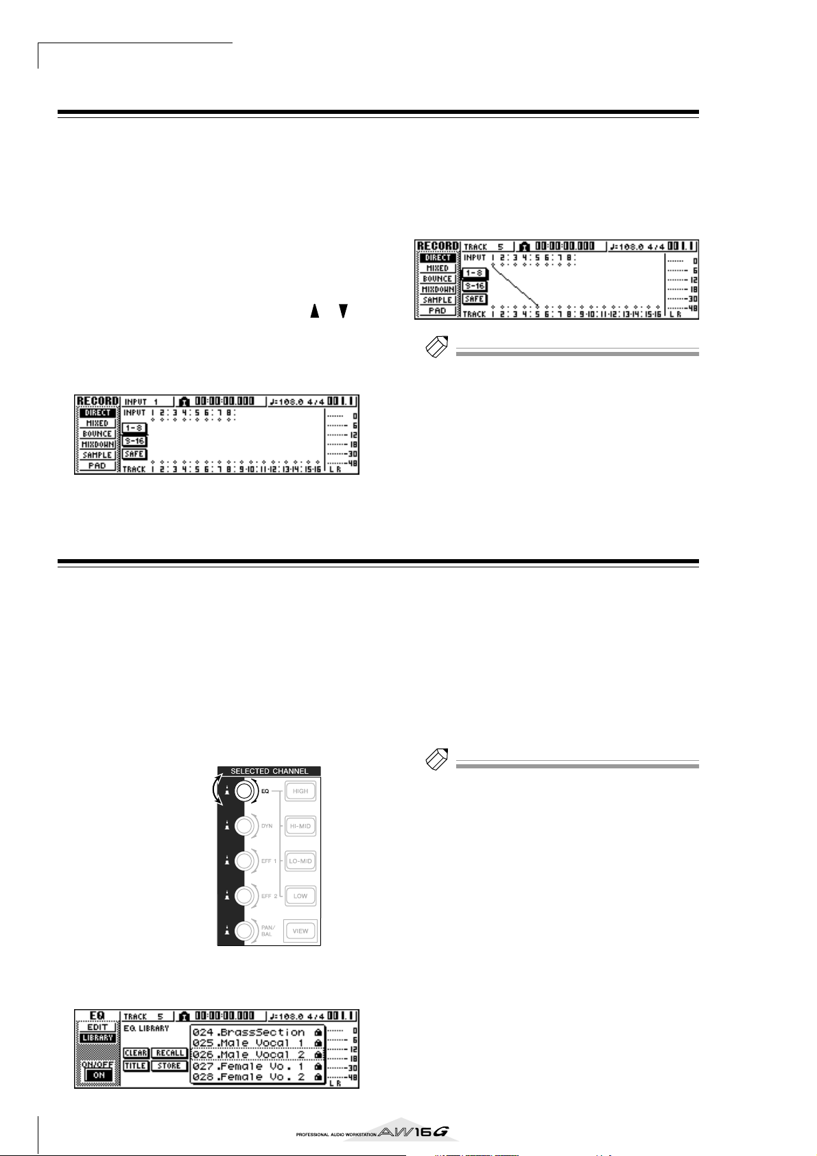
Overdubbing
Tip!
Tip!
Assigning the input signal to a track
In order to overdub, you must first assign the mic or
instrument to a new track. The basic procedure is the
same as when recording the first track.
Lower the [STEREO] fader to the –∞ position.
1
Connect your instrument or mic to a MIC/
2
LINE INPUT jack.
In the Work Navigate Section, repeatedly
3
press the [RECORD] key or hold down the
[RECORD] key and use the CURSOR [ ]/[ ]
keys to access the DIRECT page of the
RECORD screen.
The [INPUT SEL] key and [TRACK SEL] key will
blink red.
Assign the input channel to which your
4
instrument/mic is connected to a new track,
and adjust the level.
For details on this step, refer to “Track recording” (→
p. 39). The diagram below shows an example of
when input channel 1 is assigned to track 5.
Tip!
In this example we will use “direct recording,” in which
one input channel is assigned to one track. However, you
may also use “bus recording,” in which multiple input
channels are sent to the L/R bus and recorded on one or
two tracks.
Instantly recalling an EQ library
The chapter entitled “Track recording” explained how to
access the LIBRARY page of the EQ screen and load an
EQ library to change the EQ. This section explains how
you can instantly recall an EQ library.
Press the [INPUT SEL] key of the input chan-
1
nel for which you want to use a library.
The corresponding input channel will be selected
for operations.
In the Selected Channel section, press down
2
the [EQ] knob and turn it.
Turn while pressing
Turn the [DATA/JOG] dial to select an EQ
3
library. Then move the cursor to the RECALL
button and press the [ENTER] key.
The selected library will be loaded.
If you want to adjust the EQ settings, use the
4
[HIGH] key, [HI-MID] key, [LO-MID] key, and
[LOW] key of the Selected Channel section to
select the EQ band, and turn the [EQ] knob
to adjust the amount of boost or cut.
Tip!
If necessary, you can make detailed adjustments to EQ
parameters such as the center frequency and Q (→ p. 92).
When you turn the [EQ] knob to left or right while
pressing it, the LIBRARY page of the EQ screen will
appear.
56
Page 57

Instantly recalling a dynamics library
Tip!
Tip!
A dynamics library can be instantly recalled in the same
way as an EQ library.
In the Selected Channel section, press down
1
the [DYN] knob and turn it.
Turn while pressing
When you turn the [DYN] knob to left or right while
pressing it, the LIBRARY page of the DYN screen
will appear.
Turn the [DATA/JOG] dial to select a DYN
2
library. Then move the cursor to the RECALL
button and press the [ENTER] key.
The selected library will be loaded.
If you want to adjust the dynamics effect,
3
turn the [DYN] knob in the Selected Channel
section.
Tip!
• In the same way, you can press and turn the [EFF1] knob
or [EFF2] knob in the Selected Channel to recall an
effect library.
• If necessary, you can make detailed adjustments to the
dynamics parameters (→ p. 93).
6
Overdubbing
Setting the mix balance and pan
Here’s how to set the volume balance and pan for the
previously-recorded tracks and the tracks that you now
will be overdubbing.
While you play back the song, raise the track
1
channel faders for the previously-recorded
tracks to an appropriate monitoring level.
Press the track channel [TRACK SEL] key for a
2
previously-recorded track, and use the [PAN/
BAL] knob of the Selected Channel section to
set the pan.
Stop the recorder, and while producing
3
sound on your instrument, adjust the fader of
the recording-destination track channel so
that the monitoring level is appropriate.
The track channel for the recording-destination
track will send the input signal to the stereo bus
while recording or stopped, and will send the track
playback signal to the stereo bus during playback.
This means that in order to monitor the input signal,
you must stop the recorder.
Press the [TRACK SEL] key for the recording-
4
destination track channel, and use the [PAN/
BAL] knob of the Selected Channel section to
set the pan.
In the same way as for the input channel signal, you
can also use EQ and dynamics to process the track
channel. To do this, press the [TRACK SEL] key to
select the track channel, and use the [EQ] knob or
[DYN] knob of the Selected Channel section to
recall a library and adjust the settings. This procedure will not affect the signal that is recorded on the
track.
Tip!
The position of the track channel faders will not affect
the recording level. However if you set the faders to 0 dB,
the playback volume will be the same as when you
recorded the tracks.
57
Page 58
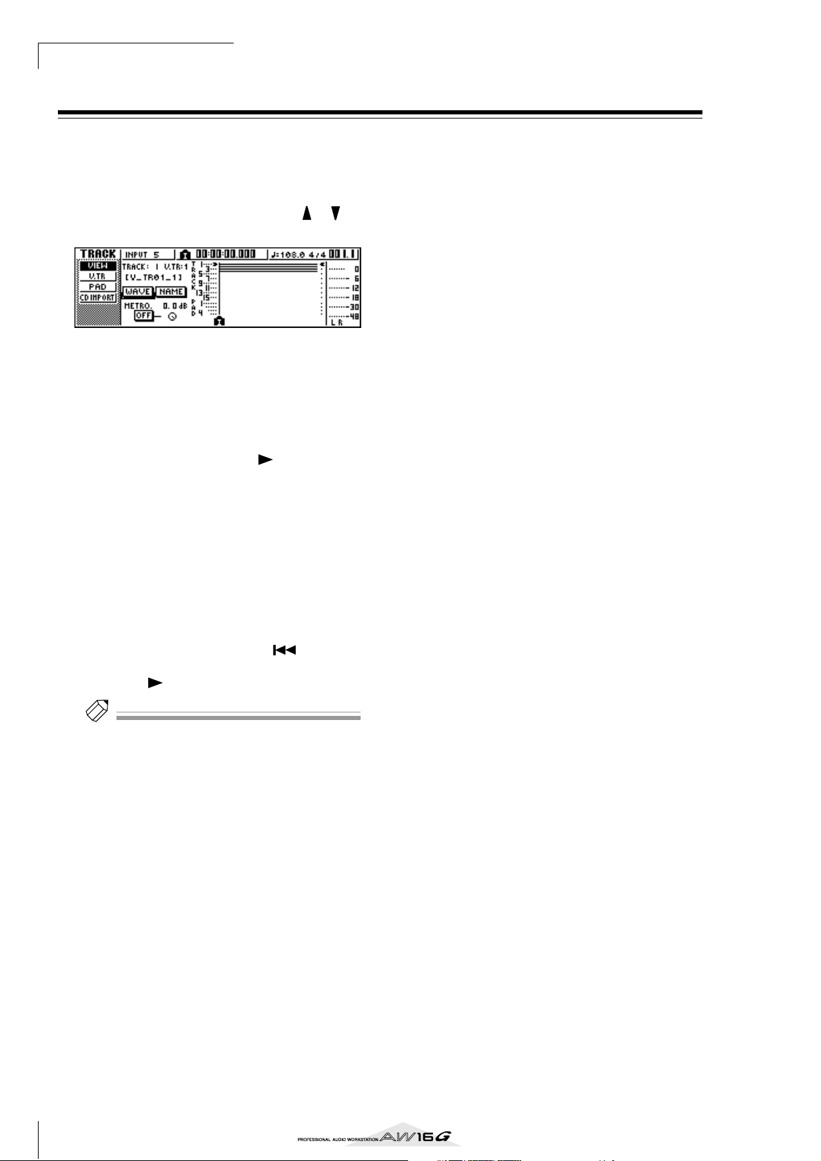
Overdubbing
Tip!
Overdubbing
Now you can overdub onto the track that you selected as
the recording-destination.
In the Work Navigate section, repeatedly
1
press the [TRACK] key or hold down the
[TRACK] key and use the CURSOR [ ]/[ ]
keys to access the VIEW page.
Move the cursor to the metronome button,
2
and press the [ENTER] key to switch the setting on or off as desired.
You can perform overdubbing whether the metronome is on or off.
In the transport section, hold down the REC
3
[●] key and press the PLAY [ ] key.
The metronome will begin sounding, and the
counter display will advance.
While monitoring the previously-recorded
4
tracks, play the instrument that you want to
overdub.
To stop recording, press the STOP [■] key.
5
The [UNDO/REDO] key in the data entry / control
section will light.
To listen to the recorded performance from
6
the beginning, press the RTZ [ ] key to
return the counter display to zero, and press
the PLAY [ ] key.
Tip!
If you recorded from the middle of the song, you can
press the [IN] key to move to the location at which you
began recording.
If you are satisfied with the recorded perfor-
7
mance, save the song. (For details on saving
→ p. 63)
If you decide to re-do the recording, press the
[UNDO/REDO] key to cancel the recording, and
repeat steps 3–7.
58
Page 59

Punch-in/out
If you make a mistake while overdubbing, you can rerecord just the region in which you made the mistake.
This process is called “punch-in/out.”
Punch-in/out can be performed either as “manual punchin/out” in which you switch between recording and playback manually, or as “auto punch-in/out” in which
recording and playback will switch automatically when
you reach the locations you specify beforehand.
Manual punch-in/out
Here’s how to perform punch-in/out using the keys of the
transport section or a foot switch.
If you want to perform punch-in/out using a
1
foot switch, connect a separately sold foot
switch (Yamaha FC5 or equivalent) to the
rear panel FOOT SW jack.
Access the DIRECT page of the RECORD
2
screen, and make sure that your instrument/
mic is assigned to the track on which you
want to punch-in.
At this time, the [INPUT SEL] key of the recordingsource and the [TRACK SEL] key of the recordingdestination will blink red.
At the point where you want to stop record-
6
ing, press the PLAY [ ] key (or press the foot
switch).
The recording-destination track will switch from
recording back to playback (“punch-out”).
To stop playback, press the STOP [■] key (or
7
press the foot switch).
To listen to the newly-recorded content,
8
locate to a point just before the punch-in
point, and press the PLAY [ ] key.
If you are satisfied with the newly-recorded
9
content, save the song. (For details on saving
→ p. 63)
If you decide to re-do the recording, press the
[UNDO/REDO] key to cancel the recording, and
repeat steps 4–9.
The following diagram shows the manual punch-in/
out procedure.
1
2
3
4
5
16
play playrecord
6
Overdubbing
Locate to a point earlier than where you want
3
to punch-in.
You may find it convenient to register a marker at a
location one or two measures earlier than the point
at which you want to punch-in, so you can quickly
return to that point. (For details on registering a
marker → p. 67)
In the transport section, press the PLAY [ ]
4
key. (Alternatively, press the foot switch.)
The song will begin playing. At this time, the track
playback sound of the recording-destination track
channel will be sent to the stereo bus, so you will
not be able to monitor the input signal.
At the point where you want to begin
5
recording, hold down the PLAY [ ] key and
press the REC [●] key (or press the foot
switch once again), and begin playing your
instrument.
The recording-destination track will switch from
playback to recording (“punch-in”).
The recording-source [INPUT SEL] key and the
recording-destination [TRACK SEL] key will light
red, and the signal of the corresponding track channel will switch from the track playback to the input
signal.
punch-in punch-out
Auto punch-in/out
Auto punch-in/out is a function that performs the punchin and punch-out operations automatically. In order to
use this function, you must first specify the punch-in
location (the In point) and the punch-out location (the
Out point).
Access the DIRECT page of the RECORD
1
screen, and make sure that your instrument/
mic is assigned to the track on which you
want to punch-in.
The recording-source [INPUT SEL] key and the
recording-destination [TRACK SEL] key will blink
red.
59
Page 60

Overdubbing
Tip!
Tip!
Locate to the point at which you want to
2
punch-in.
In the Locate section, hold down the [SET]
3
key and press the [IN] key.
The current location will be registered as the In
point.
Locate to the point at which you want to
4
punch-out.
In the Locate section, hold down the [SET]
5
key and press the [OUT] key.
The current location will be registered as the Out
point.
Tip!
• If you want to set the In and Out points more precisely,
you can use the Nudge function (→ p. 71) which repeatedly plays a short region before or after the current
location, or use the WAVE DISPLAY popup window (→
p. 72) which lets you view the contents of the track as a
waveform.
• The In point and Out point will be updated each time
you record. The location at which you last started
recording will be registered as the In point, and the
location at which you last stopped recording will be
registered as the Out point.
In the Locate section, press the [AUTO
6
PUNCH] key.
The [AUTO PUNCH] key will light, and the Auto
Punch-in/out function will be enabled. You will
automatically locate to a point a specific distance
(the “pre-roll time”) ahead of the In point. This point
is called the “pre-roll point.”
To rehearse the auto punch-in/out, press the
7
PLAY [ ] key.
1 The PLAY [ ] key will light, and playback will
begin from the pre-roll point.
B When you reach the auto punch-in point, the
REC [●] key will begin blinking, and the signal
that you are monitoring from the recordingdestination track channel will switch from the
track playback to the input signal (recordingsource). (However, recording will not actually
occur.)
C When you reach the auto punch-out point, the
REC [●] key will go dark, and the signal that
you are monitoring from the recording-destination track channel will return to the track
playback.
D When you reach a point that is a specific dis-
tance (the “post-roll time”) after the Out point
(this point is called the “post-roll point”), you
will return to the pre-roll point and stop.
To perform the actual auto punch-in/out,
8
stop the recorder, then hold down the REC
[●] key and press the PLAY [ ] key.
1 Only the PLAY [ ] key will light, and play-
back will begin from the pre-roll point.
B When you reach the auto punch-in point, the
REC [●] key will light, and recording will begin
(“punch-in”).
C When you reach the auto punch-out point, the
REC [●] key will go dark, recording will stop,
and you will return to playback mode
(“punch-out”).
D When you reach the post-roll point, you will
return to the pre-roll point and stop.
To check the newly-recorded content, press
9
the [AUTO PUNCH] key to make it go dark,
and then press the PLAY [ ] key.
If you are satisfied with the newly-recorded
10
content, save the song. (For the Save procedure → p. 63)
If you decide to re-do the recording, press the
[UNDO/REDO] key to discard the newly-recorded
content, and repeat steps 6–9.
The following diagram shows the auto punch-in/out
procedure.
Auto
punch-out
point
1
2
3
4
5
16
actual recording
locate
Pre-roll
point
rehearsal
Auto
punch-in
point
play playrehearsal
punch-in punch-out
Post-roll
point
Tip!
• If you turn the Locate section [REPEAT] key on before
step 7, operations 1–4 of step 7 will be repeated up
to fifteen times. (The A-B Repeat function is disabled
during this time.) If you want to stop repeating the
rehearsal, press the [REPEAT] key once again or press
the STOP [■] key.
•With the initial settings of the AW16G, the pre-roll and
post-roll times are each set to four seconds. You can
adjust these values in a range of 0–5 seconds (→ p. 162).
60
Page 61

Using the Undo List
Note
By using the AW16G’s Undo function, you can not only
cancel the most recent recording or editing operation,
but can even backtrack through your work for as many as
fifteen previous steps. This is convenient when, for example, after performing several overdubs, you decide that
you would rather go back to the state immediately after
you had recorded the third solo.
Press and hold the [UNDO/REDO] key.
1
The UNDO LIST popup window will appear.
1
1 Undo list
This is a list of the previously-performed recording
and editing operations.
From the left, the list shows a step number that indicates the order in which the operations were performed, the content of the operation, and the track/
virtual track that was affected by the recording or
editing operation.
The current song is now in the state of the step that
is highlighted.
The step enclosed by a dotted frame indicates the
step to which the Undo function will return the
song.
Turn the [DATA/JOG] dial to select a step
2
number.
Move the cursor to the OK button and press
3
the [ENTER] key.
The current song will revert to the state of the step
you selected.
6
Overdubbing
Move the cursor to the EXIT button and press
4
the [ENTER] key.
The popup window will close, and you will return
to the previous screen.
Note
Please note that if you perform recording or editing after
“undoing” back to a certain step, the undo/redo data
subsequent to that step will be erased. For example if you
“undo” the previous three steps, and then perform a
recording or editing operation, the undo/redo data for
the previous steps 1 and 2 will be erased.
61
Page 62
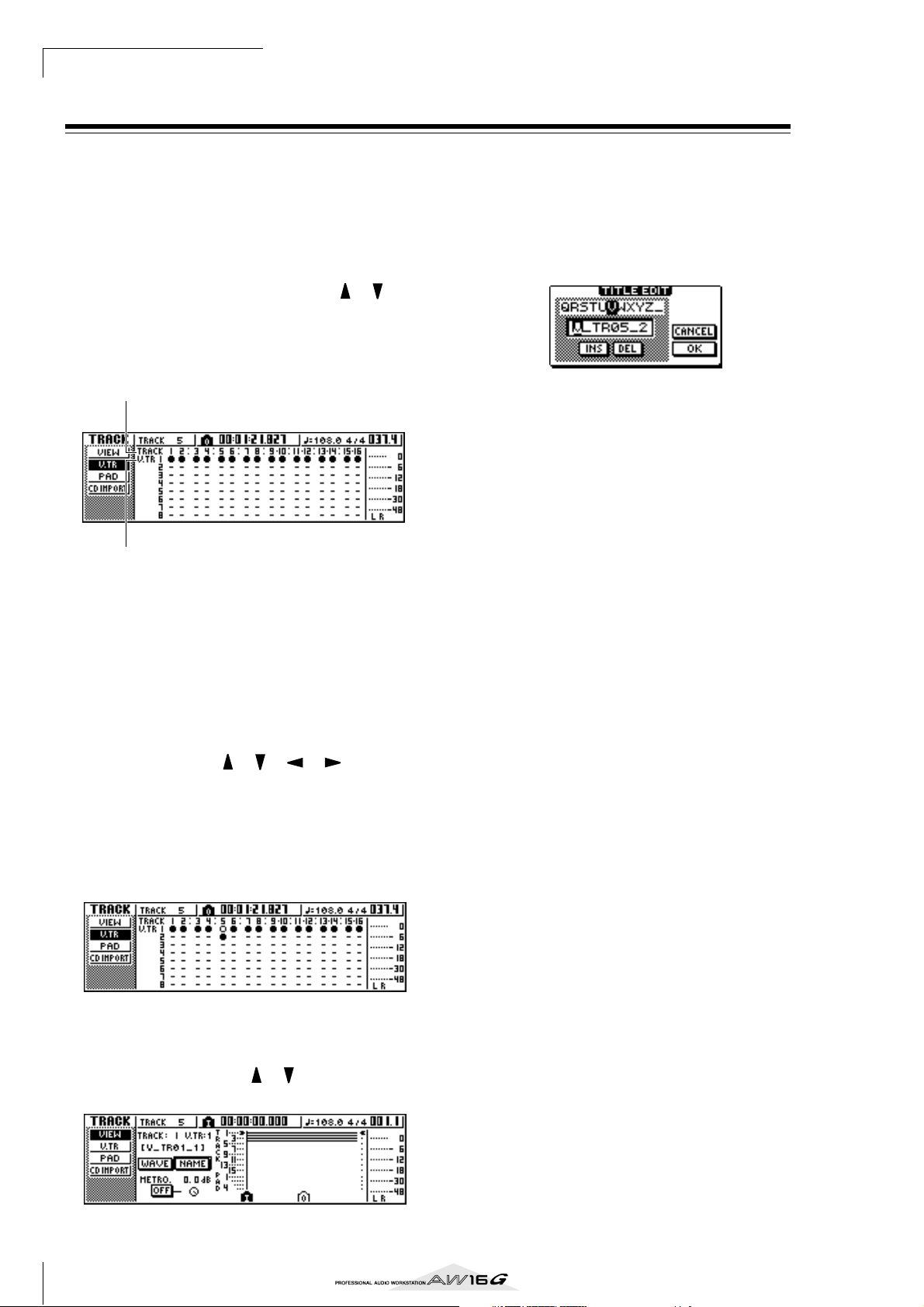
Overdubbing
Switching virtual tracks
Each audio track 1–16 contains eight virtual tracks. After
overdubbing a solo part, you can switch the virtual track
for that track, and record a different take while preserving the previously-recorded content. Here’s how to
switch the virtual track that is selected for a track.
In the Work Navigate section, repeatedly
1
press the [TRACK] key or hold down the
[TRACK] key and use the CURSOR [ ]/[ ]
keys to access the V.TR page.
In the V.TR page you can switch the virtual track (1–
8) that will be used for recording/playback by each
audio track 1–16.
1
2
1 TRACK
Indicates the track number 1–16.
B V.TR
Indicates the status of virtual tracks 1–8. The virtual
track that is currently selected for each track is indicated by a “●” symbol. Of the virtual tracks that are
currently not selected, those that have been
recorded are indicated by “❍”, and those that have
not yet been recorded are indicated as “-”.
Move the cursor to the TRACK field, and turn
5
the [DATA/JOG] dial to select a track number.
Move the cursor to the NAME button and
6
press the [ENTER] key.
The TITLE EDIT popup window will appear, allowing you to assign a name to the virtual track.
Assign a new name to the virtual track.
7
For details on how to assign a name, refer to page
24.
Use the CURSOR [ ]/[ ]/[ ]/[ ] keys to
2
select the virtual track number that you want
to assign to the desired track.
Press the [ENTER] key.
3
The “●” symbol will be displayed at the position of
the newly-selected virtual track. This virtual track
will now be used for recording/playback.
If you want to assign a name to each virtual
4
track, repeatedly press the Work Navigate
[TRACK] key or hold down the [TRACK] key
and use the CURSOR [ ]/[ ] keys to access
the VIEW page.
62
Page 63

Saving the current song
Note
Tip!
This section explains how to save the current song to the
hard disk. If you accidentally turn off the power of the
AW16G without saving the song, all recordings or operations that you performed since last saving the song will
be lost. You should make a habit of saving the song at
appropriate breaks in your work.
In the Work Navigate section, repeatedly
1
press the [SONG] key or hold down the
[SONG] key and use the CURSOR [ ]/[ ]
keys to access the LIST page.
In this page you can select a song on the hard disk,
and load or delete it.
12
3
1 List
This is a list of the songs saved on the hard disk. The
line enclosed by a dotted frame in the center of the
list is the song to which your operation you perform
will apply. The highlighted line is the song that is
currently loaded into the AW16G. (This is referred
to as the “current song.”)
B SORT field
Use these three buttons to select how the songs in
the list will be sorted. You can choose NAME (sort
alphabetically), OLD (sort by date of saving), or
SIZE (sort by size).
C SAVE button
When you move the cursor to this button and press
the [ENTER] key, the current song will be saved.
To save the song, move the cursor to the OK
3
button and press the [ENTER] key.
If you move the cursor to the CANCEL button
(instead of the OK button) and press the [ENTER]
key, the Save operation will be cancelled.
Note
• The song save operation always saves the current song,
regardless of the song that is selected in the list.
•You cannot save a song that is protected. If for example
you have edited the mixer settings and need to save the
song, you must disable the protect setting and then save
the song. (Making various settings for a song → p. 139)
Tip!
• If necessary, you can change the name of the song
before you save it (→ p. 138).
• In the following situations, a popup window will ask
whether you want to save the current song; when you
load an existing song from the hard disk, when you create a new song, or when you shut-down the AW16G.
• However, we recommend that you frequently save the
song you are working on, as a safeguard against accidents such as the AW16G’s power cable being accidentally disconnected.
6
Overdubbing
Move the cursor to the SAVE button and
2
press the [ENTER] key.
A popup window will ask you to confirm that you
want to save the current song.
63
Page 64

Overdubbing
Note
Loading an existing song
Here’s how to load an existing song from the hard disk.
In the Work Navigate section, repeatedly
1
press the [SONG] key or hold down the
[SONG] key and use the CURSOR [ ]/[ ]
keys to access the LIST page.
Turn the [DATA/JOG] dial to select a song.
2
Move the cursor to the LOAD button in the
3
screen, and press the [ENTER] key.
A popup window will ask you whether you want to
save the current song.
Move the cursor to either YES (if you want to
4
save the current song) or NO (if you do not
want to save the current song), and press the
[ENTER] key.
The song you selected will be loaded.
Note
If you select NO, all changes you made after last saving
the current song will be lost.
64
Page 65

Chapter 7
Tip!
Tip!
Various types of playback
This chapter explains how to use the locator and marker functions,
and various other playback methods provided by the AW16G.
Using the locator
“Locate points” are locations you specify within a song
in order to execute functions such as auto punch-in/out
and A-B repeat. You can use this function to “locate”
(move the current location of the song) to one of these
points just by pressing a single key. On the AW16G, you
can use the following locate points.
● In/out points
These locate points are used to specify the region for
auto punch-in/out (→ p. 59). Normally, the beginning
and end of the recording you last performed will be
automatically set as the In point and Out point. However, you may change these points as desired.
● A/B points
These locate points are used to specify the region for
the A-B Repeat function (→ p. 70). The A point and B
point can be set to any point in a song, either by
pressing a key or by operations in the screen.
● Start/end points
These locate points normally correspond to the
beginning and end of the song. When you create a
new song, the Start point will initially be set to absolute time 00:00:00.000. When you record, the end of
the song will automatically be set as the End point. If
you record past the previously-set End point, the End
point will automatically move back.
If you select SEC or T.C. as the counter display format,
the Start point will be the basis (the zero point) of the
time and time code that are displayed. This means
that if you change the Start point, the display will
change as follows, depending on the counter display
format.
Tip!
When you create an audio CD, the Start and End points
can be used to specify the region of the stereo track that
will be written to the audio CD (→ p. 98).
Start point
Counter
display format
Start point
Counter
display format
= 00:00:00:00.00
00:00:00:00.00 00:00:05:00.00 00:00:10:00.00
ABS
00:00:00:00.00 00:00:05:00.00
SEC
00:00:00:00.00 00:00:05:00.00
T.C
S
= 00:00:05:00.00
00:00:00:00.00 00:00:05:00.00 00:00:10:00.00
ABS
–00:00:05:00.00 00:00:00:00.00 00:00:05:00.00
SEC
23:59:55:00.00 00:00:00:00.00 00:00:05:00.00
T.C
S
00:00:10:00.00
00:00:10:00.00
Tip!
When the AW16G transmits MTC to an external device,
the Start point will be the basis (the zero point) of the
time code that is generated. The Start point will also be
the basis (measure 1 beat 1) for the measures displayed in
the counter.
● Relative zero point
This locate point stores the relative zero position.
When you press the RTZ [ ] key in the transport
section, you will move to this location. If the song is
in the initial state, the relative zero point will be the
same as absolute time 00:00:00.000, but you can
change this if desired by using key operations or
operations in the screen.
If you select REL as the counter display format, the
current location will be displayed with the Relative
Zero point as 0.
65
Page 66

Various types of playback
Note
Tip!
The following procedure shows how to register the
current location in one of the locate points, and then
move the song to that locate point.
Move the song to the point that you want to
1
register as a locate point.
You can set a locate point whether the song is playing or stopped.
Hold down the [SET] key and press the key
2
for the desired locate point.
The locate points correspond to the following keys.
In point
Out point
A point
B point
Relative Zero
point
To move to a locate point you registered,
3
press the corresponding key while the song is
stopped or playing.
The song will move to that location, and an icon
will appear at the left side of the counter to indicate
the currently selected locate point.
Locator icon
This icon will remain visible until you play or
rewind/fast-forward past the previous or next locate
point or marker location.
Locate points that you register are displayed in the
TRACK screen VIEW page or PAD page as shown
below.
Locator icon
Tip!
•Locate point settings are stored on the hard disk as part
of the song.
•Locate points can be adjusted as desired (→ p. 68).
Locate points other than the Start point and End point
may also be erased (→ p. 69).
[IN] key...................... In point
[OUT] key.................. Out point
[A] key ....................... A point
[B] key........................ B point
RTZ [ ] key ......... Relative Zero point
Note
• If you want to change the Start point or End point, use
the SONG screen POINT page. These points cannot be
set by key operations.
• The In point and Out point will be updated automatically when you perform a recording operation.
66
Page 67

Using markers
Tip!
Note
Tip!
“Markers” are symbols that you assign at desired locations in a song, so that you can move quickly to a desired
point. You can assign up to 99 markers in each song. Use
the [ ]/[ ] keys to find and move to markers.
Move to the position in the song at which
1
you want to assign a marker.
You can assign a marker whether the song is playing
or stopped.
Press the [MARK] key.
2
The top line of the display will briefly indicate
“MARK POINT SET.” This indicates that a marker
has been set. A new marker will be added each
time you press the [MARK] key.
Markers are automatically numbered 1–99 starting
at the beginning of the song. If you register a new
marker between two existing markers, subsequent
markers will be automatically renumbered upward.
Register a new marker
Press the [ ] key to locate to the previous
3
marker, or press the [ ] key to locate to the
next marker.
The song will move to that location, and an icon
will appear at the left of the counter to indicate the
currently selected marker number.
Marker icon
This icon will remain visible until you play or
rewind/fast-forward past the previous or next locate
point or marker location.
Markers that you register are displayed in the
TRACK screen VIEW page or PAD page as shown
below.
7
Various types of playback
Tip!
•Marker settings are stored on the hard disk as part of
the song.
•Markers can be deleted (→ p. 69) or moved (→ p. 68) as
desired.
• If you press the [MARK] key at a location in which a
marker has already been registered, the display will
indicate “CANNOT SET MARK,” and a new marker will
not be created.
Marker icon
Note
Markers other than the marker displayed at the left of the
counter are shown as icons without a number, and indicate their approximate location.
Tip!
When creating an audio CD, you can use markers to
divide the stereo track into the tracks that will be written
to the audio CD (
→
p. 98).
67
Page 68

Various types of playback
Tip!
Note
Adjusting the position of a locate point or
marker
Here’s how you can adjust the position of a previouslyregistered locate point or marker.
In the Work Navigate section, repeatedly
1
press the [SONG] key or hold down the
[SONG] key and use the CURSOR [ ]/[ ]
keys to access the POINT page.
In the POINT page you can adjust the time location
of each locate point and marker.
2 31
1 LOCATOR button
B MARKER button
These buttons select whether the screen will show
locate points or markers. The button that is currently
turned on will be highlighted.
C Locator point/marker display area
This area shows a list of the locate points or markers, depending on whether you have selected the
LOCATOR button or the MARKER button.
If you want to adjust the position of a locate
2
point, make sure that the LOCATE button is
turned on (highlighted) in the display.
When the LOCATOR button is on, the POINT page
will display the positions of each locate point.
The format in which the position is displayed will
depend on the locate point. The following table
shows the display format for each locate point.
Locate
point
REL.ZERO Time code
START Time code Measure/beat
END Time code Measure/beat
IN Counter display format Measure/beat
OUT Counter display format Measure/beat
A Counter display format Measure/beat
B Counter display format Measure/beat
POSITION field MEAS field
Tip!
If a locate point has not been registered, the numerical
field will indicate “–”.
Move the cursor to the locate point value
3
that you want to adjust, and turn the [DATA/
JOG] dial to change the value.
Only in the case of the Start point, a “Change
START Position?” popup window will ask you for
confirmation when you attempt to change the
value. Move the cursor to the OK button and press
the [ENTER] key, and then change the value.
Note
Changing the Start point will mean that locations already
recorded in a track will move relative to the measure
lines defined by the tempo map. Please be aware of this if
you are using measure display for the metronome or for
the quick loop sampler.
1 2 3
1 Locate points
Shows the type of locate point and its abbreviation.
B POSITION
Shows the position of each locate point as time
code or the counter display format.
C MEAS
Shows the position of each locate point as measures/beats. This value is calculated according to
the tempo and time signature of the tempo map (→
p. 142).
To adjust the location of a marker, move the
4
cursor to the MARKER button in the display
and press the [ENTER] key.
When the MARKER button is on, the POINT page
will list the markers that have been registered.
2 3 4
5
1 List
Lists the markers that have been registered. The line
that is enclosed by a dotted frame is selected for
operations.
B MARKER
These are the marker numbers 01–99.
C POSITION
Shows the position of each marker, in the counter
display format.
1
68
Page 69
D MEAS
Note
Note
Shows the position of each marker, in measure/beat
units.
E DELETE button
To delete the currently selected marker, move the
cursor to this button and press the [ENTER] key.
Move the cursor to the MARKER area, and
5
turn the [DATA/JOG] dial to scroll the list so
that the dotted frame encloses the marker
number that you want to edit.
Move the cursor to the value that you want
6
to edit, and turn the [DATA/JOG] dial to edit
the value.
Note
You cannot change the location beyond the next or previous marker.
Erasing a locate point or marker
If necessary, you can erase a previously-registered locate
point (except for the Relative Zero, Start, and End points)
or marker.
Note
A locate point that you erase cannot be recovered.
■ Erasing a locate point
To erase a locate point, hold down the [CANCEL] key in
the Locate section, and press the corresponding locate
key ([IN]/[OUT] key, [A]/[B] key). That locate point will
be erased, and a message of “LOCATE POINT ERASED”
will be displayed for a time.
■ Erasing a marker
You can erase a marker in one of two ways; using key
operations, or in the screen.
To erase a marker using key operations, locate to the
marker that you want to erase. Then hold down the
[CANCEL] key of the Locate section and press the
[MARK] key. The corresponding marker will be erased,
and a message of “MARK POINT ERASED” will be displayed for a time.
To erase a marker by operations in the screen, access the
list of markers in the POINT page of the SONG screen,
select the marker that you want to erase, move the cursor
to the DELETE button and press the [ENTER] key.
7
Various types of playback
69
Page 70

Various types of playback
Tip!
Note
Tip!
Tip!
Repeatedly playing a specific region
(the A-B Repeat function)
The AW16G provides an “A-B Repeat” function that
repeatedly plays the region between the A point and B
point. This is useful when you want to repeatedly play
back a certain region of the song while you adjust the
mix.
Register the A point and B point to the loca-
1
tions at which you want the repeated playback to start and end.
For details on how to set the A point and B point,
refer to “Using markers” (→ p. 67).
Tip!
If you set the B point earlier than the A point, the B -> A
region will play repeatedly.
While the transport is stopped, press the
2
[REPEAT] key.
The [REPEAT] key will light, and the A-B Repeat
function will be on. The song will automatically
locate to the A point.
Note
The A and B points must be at least one second apart. If
they are closer than this, a message of “REPEAT POINTS
TOO CLOSE” will appear when you press the [REPEAT]
key, and repeat playback will not be possible.
To begin repeat playback, press the PLAY
3
[] key.
Playback will begin from the A point. When you
reach the B point, you will automatically return to
the A point and continue playback.
Tip!
• Playback will stop automatically when the A/B region
has been repeated 99 times.
• If you press the [REPEAT] key while the song is playing,
repeat playback between the A and B points will begin
automatically, regardless of the current position.
To stop playback, press the STOP [■] key.
4
Playback will stop, but the A-B Repeat function will
remain turned on.
When the A-B Repeat function is on, pressing the
PLAY [ ] key will immediately resume repeat
playback, regardless of the current position.
To cancel repeat playback, press the [REPEAT]
5
key.
The [REPEAT] key will go dark, and the A-B Repeat
function will be cancelled. If you cancel the A-B
Repeat function during repeat playback, normal
playback will occur from that point.
Tip!
If you perform a recording operation while the A-B
Repeat function is on, the A-B Repeat function will be
temporarily disabled.
70
Page 71

Finding a location while you listen to the
Tip!
Note
sound (the Nudge function)
“Nudge” is a function that repeatedly plays a short region
before or after the current location. By using the Nudge
function, you can find a precise location while listening
to the playback. This is useful when you need to specify a
location precisely, such as when specifying the auto
punch-in/out points, or when editing the contents of a
track.
Locate to the vicinity of the point you want
1
to find.
With the transport stopped, press the [JOG
2
ON] key.
The [JOG ON] key will light, and the Nudge function will be turned on. A fixed region (referred to as
the “nudge time”) starting at the current location
will play repeatedly.
To move the current location forward, turn
3
the [DATA/JOG] dial toward the right. To
move the current location backward, turn
the [DATA/JOG] dial toward the left.
If time display is selected as the counter display format, you can move the current location forward or
backward in millisecond units. If time code display
is selected, you can move in sub-frame units.
Current
location
If you want to change the playback duration
5
or the playback mode, repeatedly press the
Work Navigate section [UTILITY] key or hold
down the [UTILITY] key and use the CURSOR
[ ]/[ ] keys to access the PREFER page of
the UTILITY screen.
1 NUDGE MODE
Specifies the region of sound (before or after the
current location) that will be played by the Nudge
function.
B NUDGE TIME
Specifies the duration of the region that will be
played by the Nudge function.
To change the playback duration (nudge
6
time), move the cursor to the value of the
NUDGE TIME field, and use the [DATA/JOG]
dial to set the nudge time.
You can set the nudge time in a range of 25 ms –
800 ms. (Default = 500 ms).
12
7
Various types of playback
Song
track
Nudge time
Tip!
Even while using the Nudge function, you can use locate
points or markers to change the location, or register
locate points or markers (→ p. 65).
To turn off the Nudge function, press the
4
[JOG ON] key or the transport section STOP
[■] key.
The [JOG ON] key will go dark, and the Nudge
function will be turned off.
To change the playback position (nudge
7
mode), move the cursor to the NUDGE
MODE button, and press the [ENTER] key to
switch between the following two nudge
modes.
● AFTER
Repeatedly play for the duration of the nudge time,
starting at the current location (default).
● BEFORE
Repeatedly play for the duration of the nudge time,
ending at the current location.
NUDGE MODE: BEFORE NUDGE MODE: AFTER
Current location Current location
Note
You cannot change the nudge time or nudge mode while
using the Nudge function. You must turn off the Nudge
function, and change these settings while the [JOG ON]
key is dark.
71
Page 72

Various types of playback
Tip!
Tip!
Finding a location while you view the
waveform
The AW16G lets you find a location while viewing the
waveform of the sound recorded on the track.
Locate to the vicinity of the point you want
1
to find.
Repeatedly press the Work Navigate section
2
[TRACK] key or hold down the [TRACK] key
and use the CURSOR[ ]/[ ] keys to access
the VIEW page of the TRACK screen.
Move the cursor to the TRACK field, and turn
3
the [DATA/JOG] dial to select the number of
the track whose waveform you want to view.
Move the cursor to the WAVE button and
4
press the [ENTER] key.
The WAVE DISPLAY popup window will appear.
This popup window displays the waveform of the
audio data recorded in the current track of the track
(1–16) you selected in step 3.
1 32
D AMP
By moving the cursor to this area and turning the
[DATA/JOG] dial, you can expand or shrink the
waveform display in the amplitude axis. The value
of this field indicates the level range of the waveform displayed in the WAVE DISPLAY popup window. If you select 0 dB, the top and bottom edges of
the screen will correspond to the maximum level.
E LISTEN button
If you move the cursor to this button and press the
[ENTER] key, the waveform in the display area of
the WAVE DISPLAY popup window will be played
once. During playback, the vertical line (pointer)
that indicates the current location will move, and
the counter value will also change.
You cannot perform conventional transport operations when playing back by pressing the LISTEN
button.
F EXIT button
If you move the cursor to this button and press the
[ENTER] key, you will exit the WAVE DISPLAY
popup window and return to the previous VIEW
page.
Tip!
Even after displaying the WAVE DISPLAY popup window,
you can use the [TRACK SEL] keys to switch the track for
viewing.
645
1 TRACK
Indicates the currently selected track number. You
can also move the cursor to this field and turn the
[DATA/JOG] dial to switch tracks.
B Counter
Displays the location of the vertical line (pointer)
indicating the current location in the WAVE DISPLAY popup window. You can move the cursor to
this field and turn the [DATA/JOG] dial to move the
current location forward or backward.
C TIME
By moving the cursor to this area and turning the
[DATA/JOG] dial, you can expand or shrink the
waveform display in the time axis. The value of this
field indicates the length of time displayed in the
WAVE DISPLAY popup window.
If you select 1SEC, the distance from the left edge to
the right edge of the screen will correspond to one
second. Selecting SAMPLE will produce the highest
magnification, and each horizontal pixel will correspond to one sample (1/44,100 second).
As necessary, move the cursor to the TIME/
5
AMP fields and turn the [DATA/JOG] dial to
adjust the vertical and horizontal scale of the
waveform display.
To specify a location within the popup win-
6
dow, move the cursor to the counter and
turn the [DATA/JOG] dial.
Turning the dial toward the right will move the
pointer forward, and turning the dial toward the left
will move it backward. If necessary, you can use the
LISTEN button to play the waveform region shown
in the WAVE DISPLAY popup window, and check
the location by listening.
Tip!
•You can also change the pointer position by using the
locate points or markers that are registered in the song
(→ p. 65, 67).
• The position displayed in the counter can be registered
as a locate point or marker (→ p. 65, 67).
When you have finished specifying the loca-
7
tion, move the cursor to the EXIT button and
press the [ENTER] key.
You will return to the previous VIEW page, and the
location that you specified in the popup window
will remain the current location. As desired, register
the location as a locate point or marker.
72
Page 73
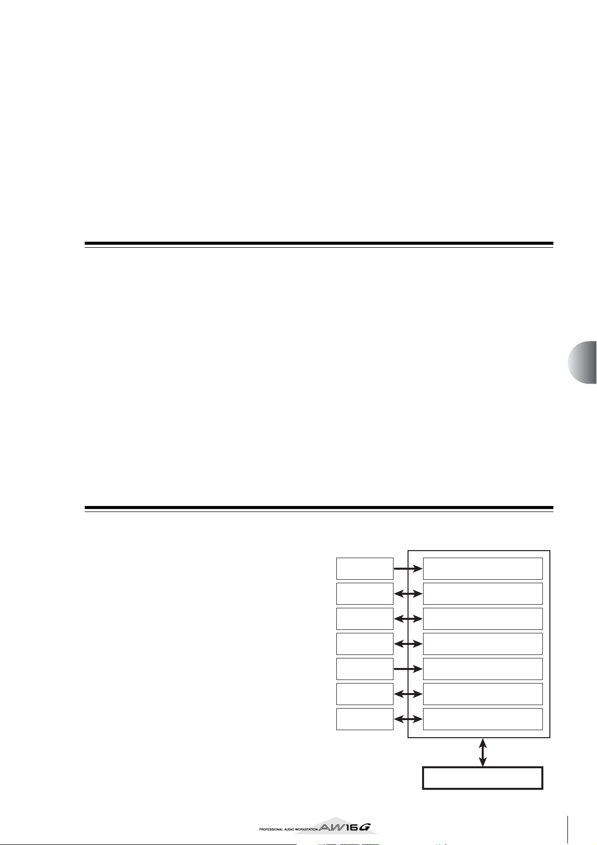
Chapter 8
Using libraries and scene
memories
This chapter explains how to use libraries and scene memories.
About the libraries
Memory areas that store settings for sections such as EQ,
dynamics, and effects are called “libraries.” By recalling
(loading) data from a library, you can instantly use the
desired set of settings. Most types of library also let you
store the current settings. The AW16G provides the following libraries.
● Input channel library
EQ, dynamics, and internal effect settings can be
loaded from this library into the currently selected
input channel. This library is read-only, and cannot
be used to store your own settings.
● EQ library
EQ settings can be loaded from this library into the
currently selected channel.
About scene memories
On the AW16G, settings for the mix parameters of all
channels and the effect parameters etc. can be stored in
internal memory as a “scene” with the name you specify.
When you recall one of the various libraries described
above, the library settings you recall will be loaded into
the settings that you are currently using (referred to as the
“current scene”). You can then save the current settings
as a scene memory, which will contain the settings that
you loaded from a library. Libraries and scene memories
are saved on the hard disk as part of the song.
The following diagram shows how libraries, scene, and
the song are related to each other on the AW16G.
● Dynamics library
Dynamics settings can be loaded from this library
into the currently selected channel.
● Effect library
Effect settings can be loaded from this library into
internal effects 1/2.
● Mastering library
EQ and dynamics settings can be loaded from this
library into the stereo channel. This library is readonly, and cannot be used to store your own settings.
● Sample library
Sets of samples can be loaded from this library into
the Quick Loop Sampler.
● Channel library
Major mix parameters can be loaded from this library
into a channel.
Current scene
Input library
EQ library EQ for the selected channel
Dynamics
library
Effect library
Mastering
library
Sample
library
Channel
library
EQ/dynamics/effects for an
input channel
Dynamics for the selected
channel
Internal effects 1/2
EQ/dynamics for the stereo
output
Sample data for the Quick Loop
Sampler
Mix parameters for each
channel
Scene memory
73
Page 74

Using libraries and scene memories
Note
Tip!
Note
Tip!
Basic operation for libraries and scene
memories
Here are the basic procedures for recalling and storing a
library or scene.
Storing library or scene data
Here’s how to store the current settings in a library or
scene memory.
Note
The input library and mastering library, and the EQ,
dynamics, or effect libraries accessed from the INPUT
SETTING popup window are all read-only, and therefore
have no STORE button.
Access the desired library page or the scene
1
memory page.
For details on how to access each library or scene
memory page, refer to the explanations on page 77
and following. The illustration below shows an
example of when you have selected the LIBRARY
page of the EQ screen.
5 3 124
Turn the [DATA/JOG] dial to scroll the list so
2
that the dotted frame encloses the library or
scene to which you want to store the data.
Regardless of where the cursor is located, turning
the [DATA/JOG] dial will scroll the list.
Move the cursor to the STORE button and
3
press the [ENTER] key.
The TITLE EDIT popup window will appear, allowing you to assign a name to the data.
Note
• If you selected read-only data (indicated by a “lock”
icon) in step 2, a message of “Read Only” will appear,
and it will not be possible to execute the Store operation.
• Scene number 00 is read-only data used to initialize the
current scene. Scene numbers 01–96 are writable data.
Assign a name to the data as desired. Then
4
move the cursor to the OK button and press
the [ENTER] key. (For details on how to
assign a name → p. 24)
The library or scene will be stored.
1 List
This area lists the data stored in the library or scene
memory. The line enclosed by the dotted frame
indicates the data that is selected for operations.
Read-only data is indicated by a “lock” icon.
B RECALL button
Recalls the library data or scene that is selected in
the list.
C STORE button
Stores the current settings into the location selected
in the list.
D CLEAR button
Deletes the library or scene that is selected in the
list.
E TITLE button
Accesses the TITLE EDIT popup window, where you
can edit the name of the library or scene selected in
the list.
Tip!
For some libraries or scene memories, buttons other than
those listed here may appear, or some of these buttons
may not appear. For details, refer to the explanations on
page 77 and following.
Tip!
You have the option of making settings so that the TITLE
EDIT popup window does not appear when you perform
the Store operation. For details, refer to “Overall settings
for the AW16G” (→ p. 162).
74
Page 75

Recalling library or scene data
Tip!
Note
Note
Deleting library or scene data
Here’s how to recall (load) settings from a library or
scene.
Access the desired library or scene memory
1
page.
For details on how to access each library or scene
memory page, refer to the explanations on page 77
and following.
The illustration below shows an example of when
you have selected the LIBRARY page of the EQ
screen.
Turn the [DATA/JOG] dial to scroll the list so
2
that the library data or scene you want to
recall is enclosed by the dotted frame.
Move the cursor to the RECALL button, and
3
press the [ENTER] key.
A popup window will ask you to confirm the Recall
operation.
Here’s how you can delete unwanted library or scene
memory data.
Note
The input library and mastering library, and the EQ,
dynamics, and effect libraries accessed from the INPUT
SETTING popup window are all read-only, and do not
have a CLEAR button.
Access the page for the desired library or
1
scene memory.
The illustration below shows an example of when
you have selected the LIBRARY page of the EQ
screen.
Turn the [DATA/JOG] dial to scroll the list so
2
that the library data or scene you want to
delete is enclosed by the dotted frame.
Move the cursor to the CLEAR button and
3
press the [ENTER] key.
A popup window will appear, asking you to confirm
the Delete operation.
8
Using libraries and scene memories
To execute the recall, move the cursor to the
4
OK button and press the [ENTER] key.
The library or scene will be recalled.
Tip!
You have the option of making settings so that the confirmation popup window does not appear when you perform the Recall operation. For details, refer to “Overall
settings for the AW16G” (→ p. 162).
Note
If you selected read-only data (indicated by a “lock”
icon) in step 2, a message will indicate “Read Only,” and
the Delete operation will not be executed.
To execute the Delete operation, move the
4
cursor to the OK button and press the
[ENTER] key.
The library or scene will be deleted.
75
Page 76

Using libraries and scene memories
Note
Note
Naming library or scene data
Here’s how you can assign a new name to existing
library or scene data.
Note
The input library and mastering library, and the EQ,
dynamics, or effect libraries accessed from the INPUT
SETTING popup window are all read-only, and therefore
have no TITLE button.
Access the page for the desired library or
1
scene memory.
The illustration below shows an example of when
you have selected the LIBRARY page of the EQ
screen.
Turn the [DATA/JOG] dial to scroll the list so
2
that the library data or scene you want to
rename is enclosed by the dotted frame.
Move the cursor to the TITLE button and
3
press the [ENTER] key.
The TITLE EDIT popup window will appear.
Note
If you selected read-only data (indicated by a “lock”
icon) in step 2, a message of “Read Only” will appear,
and you will be unable to edit the name.
Assign a name to the data. Then move the
4
cursor to the OK button and press the
[ENTER] key. (For details on assigning a name
→ p. 24)
The edited name will be finalized.
76
Page 77
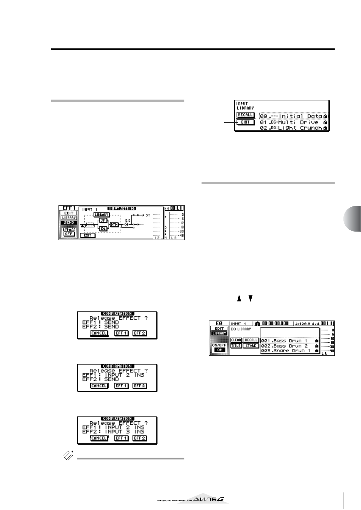
Details on libraries and scene memory
Tip!
This section explains how to access each type of library
or scene memory, and describes the functions that are
unique to each of these screens.
Input library
From this library you can recall EQ, dynamics, and internal effect settings to the currently selected input channel.
Use this when you want to apply EQ, dynamics, and
internal effects to the input signal that you are recording.
Library numbers 00–40 are all read-only, and 00 is data
for initializing an input channel.
In order to use the input library, you will need to insert
internal effect 1 or 2 into that input channel.
■ Recalling input library data
Press and hold the [INPUT SEL] key for the
1
desired input channel.
The INPUT SETTING popup window will appear.
Move the cursor to the LIBRARY button and
2
press the [ENTER] key.
A popup window will ask you whether you want to
insert internal effect 1 or 2 into that input channel.
This popup window will change as follows,
depending on how internal effects 1/2 are being
used.
● If the song is in the default state
Move the cursor to the EFF1 or EFF2 button
3
and press the [ENTER] key.
The corresponding insert effect will be inserted into
the input channel, and the INPUT LIBRARY popup
window will appear.
1
1 EXIT button
Closes the popup window and returns to the previous INPUT SETTING popup window.
EQ library
From this library you can recall EQ settings to the currently selected channel. Of library numbers 001–128,
numbers 001–040 are read-only, and 041–128 can be
written.
■ Recalling EQ library data
Use the [INPUT SEL] keys, [TRACK SEL] keys,
1
[STEREO SEL] key, or pads 1–4 to select the
channel into which you want to recall the EQ
settings.
Perform one of the following actions to
2
access the LIBRARY page of the EQ screen
• Press the [EQ] knob repeatedly
• Hold down the [EQ] knob and press the CURSOR [ ]/[ ] keys
• Hold down the [EQ] knob and turn it to left or
right
8
Using libraries and scene memories
● If effect 1 is already inserted into a specific input
channel
● If effects 1 and 2 are already inserted into specific
input channels
Tip!
If an effect has already been inserted into that input
channel, the INPUT LIBRARY popup window will appear
immediately.
You can also recall EQ library data into an input
channel directly from the INPUT SETTING popup
window. To do so, move the cursor to the EQ button
in the window and press the [ENTER] key.
77
Page 78
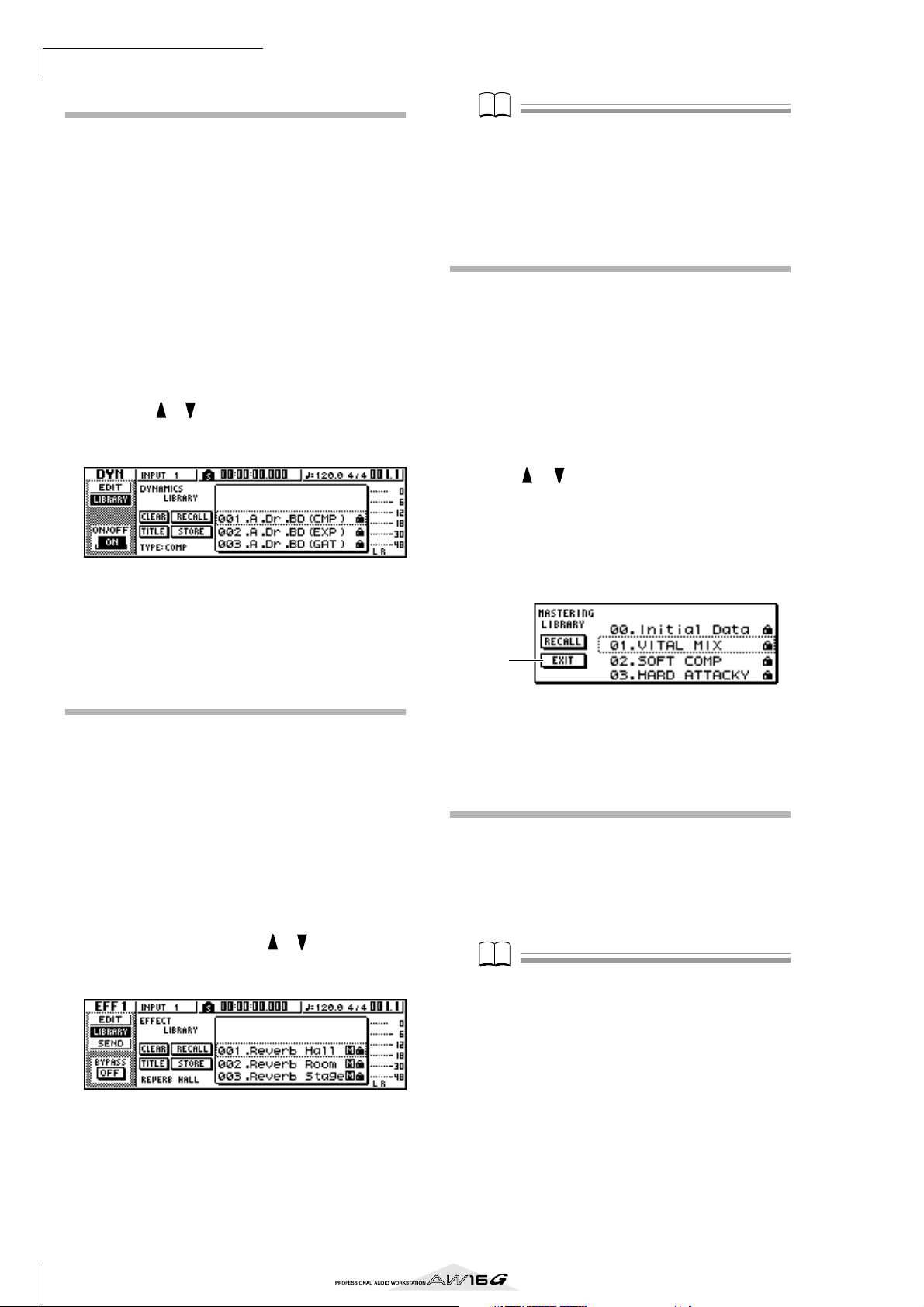
Using libraries and scene memories
Note
Note
Dynamics library
From this library you can recall dynamics settings to the
currently selected channel. Of library numbers 001–128,
numbers 001–040 are read-only, and 041–128 can be
written.
■ Recalling dynamics library data
Use the [INPUT SEL] keys, [TRACK SEL] keys,
1
[STEREO SEL] key, or pads 1–4 to select the
channel into which you want to recall the
dynamics settings.
Perform one of the following actions to
2
access the LIBRARY page of the DYN screen
• Press the [DYN] knob repeatedly
• Hold down the [DNY] knob and press the CURSOR [ ]/[ ] keys
• Hold down the [DYN] knob and turn it to left or
right
You can also recall dynamics library data into an
input channel directly from the INPUT SETTING
popup window. To do so, move the cursor to the
DYN button in the window and press the [ENTER]
key.
Note
• The [M] symbol indicates monaural input, and [S] indicates that stereo input is supported. If an effect indicated by [M] is inserted into paired channels (such as
the stereo output channel), the sense of stereo will be
lost.
• 019. HQ.Pitch cannot be recalled to effect 1.
Mastering library
This library contains settings used to apply EQ and
dynamics processing to the stereo output channel during
mixdown. It contains EQ and dynamics settings suitable
for processing the final mix. All library numbers 00–13
are read-only, and 00 is data for initializing the stereo
output channel.
■ Recalling mastering library data
Repeatedly press the [RECORD] key or hold
1
down the [RECORD] key and use the CURSOR [ ]/[ ] keys to access the MIXDOWN
page of the RECORD screen.
Move the cursor to the LIBRARY button in the
2
screen, and press the [ENTER] key.
The MASTERING LIBRARY popup window will
appear.
1
Effect library
This library is used by internal effects 1/2. Of library
numbers 001–128, numbers 001–041 are read-only, and
042–128 can be written.
■ Recalling effect library data
Perform one of the following actions to
1
access the LIBRARY page of the EFFECT 1/2
screen
• Press the [EFFECT 1] or [EFFECT 2] knob repeatedly
• Hold down the [EFFECT 1] or [EFFECT 2] knob
and press the CURSOR [ ]/[ ] keys
• Hold down the [EFFECT 1] or [EFFECT 2] knob
and turn it to left or right
You can also recall library data for an effect that has
been inserted in the input channel directly from the
INPUT SETTING popup window. To do so, move
the cursor to the EFF1 or EFF2 button in the window
and press the [ENTER] key.
1 EXIT button
Closes the popup window and returns to the previous MIXDOWN page.
Sample library
This library contains sets of up to sixteen samples for use
with the Quick Loop Sampler. Sets of drum loop or
sound-effect samples are saved on the hard disk as sample libraries. When you recall one of these, those samples will be assigned to the pads and sample banks, so
you can immediately play them from the pads.
Note
Unlike the other libraries, the sample library data is
shared by all songs.
78
Page 79

■ Recalling sample library data
Tip!
Repeatedly press the Quick Loop Sampler section [SAMPLE EDIT] key or hold down the [SAMPLE EDIT] key and
use the CURSOR [ ]/[ ] keys to access the LIBRARY
page of the SAMPLE screen.
1
4 5
32
1 SORT field
Use these three buttons to specify how the library
data in the list will be sorted. You can choose NAME
(sort alphabetically), OLD (sort by save date), or
SIZE (sort by size).
B LISTEN button
If you move the cursor to this button, press the
[ENTER] key, and then press a pad, the sample
assigned to sample bank A of the library will play.
C DELETE button
Deletes the selected library data from the hard disk.
D PROTECT button
When you move the cursor to this button and press
the [ENTER] key, the Protect setting will be
switched on/off for the library data selected in the
list. Library data for which Protect is turned on is
indicated by a “lock” icon, and cannot be edited or
deleted.
E NEW button
Creates new library data on the hard disk.
■ Recalling channel library data
Repeatedly press the Selected Channel section [VIEW]
key or hold down the [VIEW] key and use the CURSOR
[ ]/[ ] keys to access the CH LIB page of the VIEW
screen.
Tip!
• Data for parameters that do not exist in the recall-destination channel will be ignored.
• If the recall-destination is the stereo output channel or
a paired channel, the parameters will be the same for
the L and R channels, with the exception of Phase and
Pan (phase and pan settings will not change).
Scene memories
Scene memories recall the effect parameter and mix
parameter settings of all channels.
Scene number 00 is read-only data used to initialize the
current scene. Scene numbers 01–96 are writable data.
■ Recalling a scene memory
In the data entry/control section, repeatedly press the
[SCENE] key or hold down the [SCENE] key and use the
CURSOR [ ]/[ ] keys to access the LIBRARY page of
the SCENE screen.
8
Using libraries and scene memories
Channel library
This library contains mix parameter settings that can be
loaded into a channel. It is convenient to use this library
when you want to use the settings of a specific channel
for another channel. Library numbers 00–01 are readonly data for initializing a channel, and 02–64 can be
written.
Channel library data contains the following parameters.
• Channel on/off
• Attenuator
• EQ on/off
• EQ parameter settings
• Dynamics processor on/off
• Dynamics processor parameter settings
•Fader position
•Aux buses 1/2 pre-fader/post-fader setting
• Send levels to Aux buses 1/2
• Effect buses 1/2 pre-fader/post-fader setting
• Send levels to effect buses 1/2
1
1 PROTECT button
When you move the cursor to this button and press
the [ENTER] key, the Protect setting will be
switched on/off for the scene selected in the list.
Scene data for which Protect is turned on is indicated by a “lock” icon, and cannot be edited or
deleted.
79
Page 80

Using libraries and scene memories
Tip!
Using the Recall Safe function
You can specify that specific faders or specific channels
will be excluded from Recall operations when the scene
is changed either manually or from an external MIDI
device. This function is called “Recall Safe.”
For example, this is convenient if you are performing a
mixdown while switching scenes, but want to control
specific channels manually.
In the data entry/control section, repeatedly
1
press the [SCENE] key or hold down the
[SCENE] key and use the CURSOR [ ]/[ ]
keys to access the RCL SAFE page of the
SCENE screen.
1 32
1 FADER RECALL SAFE
Here you can select the fader(s) for which recall
safe will be enabled. The fader(s) you select here
will not change even when another scene is
recalled. These buttons correspond to the faders as
follows.
PAD 1–4..................... Pad channel 1–4 faders
INPUT 1–8................. Input channel 1–8 faders
TRACK 1–8,
9-10–15-16 ................ Track channel 1–8 and 9/10–15/16
faders
B ENABLE/DISABLE button
This button switches Fader Recall Safe between
ENABLE and DISABLE states. Move the cursor to
this button and press the [ENTER] key to switch the
display between ENABLE and DISABLE.
C CH RECALL SAFE
Selects the channel(s) for which Recall Safe will be
enabled. Mix parameters of the selected channel(s)
will not change even when another scene is
recalled. The buttons correspond to the following
channels.
PAD ............................All pad channels
INPUT........................ All input channels
TRACK ....................... All track channels
RTN............................ Return channels 1/2
ST OUT...................... Stereo output channel
Select the fader(s) or channel(s) that you
2
want to set to Recall Safe, and turn the corresponding button(s) on (highlighted).
If you selected a fader in step 2, move the
3
cursor to the ENABLE/DISABLE button and
press the [ENTER] key to switch the display to
ENABLE.
Fader or channel Recall Safe has now been
enabled. The selected fader(s) and/or channel(s) will
not be affected by scene recall operations until you
change this setting.
Tip!
The settings of the RCL SAFE page are shared by all
songs.
80
Page 81

Chapter 9
Mixdown and bounce operations
This chapter explains mixdown operations, in which you mix previously-recorded tracks and record the result on the stereo track. This
chapter also explains how you can use bounce (ping-pong) recording
to combine multiple tracks to one or two tracks.
About mixdown and bouncing
“Mixdown” is the process by which the signals recorded
on the recorder tracks are mixed to stereo, and recorded
on the internal stereo track to complete the song. The
contents of the stereo track can be used without further
processing as material to create an audio CD.
The diagram below shows the signal flow during mixdown. The playback of each track is sent to the stereo
bus, passes through the stereo output channel, and is
recorded on the stereo track. At this time you also add
the signals from pad channels 1–4 and input channels 1–
8.
● Signal flow during mixdown
Recorder section
Track 1
MUSIC
SYNTHESIZER
PRODUCTION
Sequencer
Sampling
Integrated
Real-timeExternalControl
Surface
Modular
SynthesisPlug-in
SONG SCENE
REC
System
Track 2
Track 3
Track 4
Pad
channels
1–4
1 2 3 4
MIC/LINE
INPUT jacks
Input
channels
1–8
Stereo bus
Track
channels
1–16
Sound
clip
Stereo
output
channel
Mixer section
81
Page 82

Mixdown and bounce operations
“Bounce” is the process by which the signals recorded
on multiple tracks are mixed to the stereo bus, and rerecorded on one or two other tracks. (This process is also
called “ping-pong recording.”)
The diagram below shows the signal flow during bouncing. This process differs from mixdown in several points;
you use the L/R bus instead of the stereo bus, only the
track channels are the recording sources, and that the
recording-destination is one or two vacant tracks. This
diagram shows an example in which the track 1–8 signals are bounced to tracks 9/10. After bouncing, you can
switch the virtual tracks for tracks 1–8, and use these
tracks to record other instrumental performances.
● Signal flow during bouncing
Recorder section
Track 1
Track 2
Track 3
Track 4
Track 5
Track 6
Track 7
Track 8
Track 9
Track 10
Track
channels
Stereo
output
channel
Stereo bus
Mixer section
82
Page 83

Preparing for mixdown
Tip!
Tip!
Note
To prepare for mixdown, select the track channels that
you will mix down, and adjust the balance and tone of
each track.
Lower the [STEREO] fader to the –∞ position.
1
In the Quick Navigate section, repeatedly
2
press the [RECORD] key or hold down the
[RECORD] key and use the CURSOR [ ]/[ ]
keys to access the MIXDOWN page of the
RECORD screen.
The MIXDOWN page is where you can perform
mixdown operations. In this page you can select the
channels that will be recorded via the stereo bus
onto the stereo track.
2 1 3
4
If you want to use the mastering library,
4
move the cursor to the LIBRARY button and
press the [ENTER] key.
The MASTERING LIBRARY popup window will
appear. Turn the [DATA/JOG] dial to select the
desired library data, then move the cursor to the
RECALL button and press the [ENTER] key.
Tip!
The mastering library contains data for loading EQ/
dynamics settings into the stereo output channel. (For
details, refer to → p. 78)
If you want to adjust the pan of each track
5
channel, repeatedly press the Selected Channel section [PAN/BAL] knob or hold down the
[PAN/BAL] knob and use the CURSOR [ ]/
[] keys to access the PAN page of the PAN
screen.
In this page you can set pairing, phase, and pan for
each channel.
1 REC button
Puts the stereo track in record-ready mode.
B SAFE button
Defeats the record-ready state of the stereo track.
C LIBRARY button
Accesses the mastering library.
D Stereo bus
Indicates the on/off status of the channels being sent
to the stereo bus. The numbers within the screen
correspond to the following channels.
INPUT 1–8................. Input channels 1–8
P1–P4......................... Pad channels 1–4
TRACK 1–16 .............. Track channels 1–16
Use the [INPUT SEL] keys,
3
[TRACK SEL] keys, and pad
keys 1–4 to select the channels
that you want to send to the
stereo bus.
The screen will change as follows
each time you press a key or pad
repeatedly.
Tip!
• All channels will be turned on by default. However in
order to obtain the best S/N ratio, you should turn off
any channels that you are not using.
•You can also add the signals of the input channels or
pad channels to the mixdown (→ p. 89).
1
2 3
1 PAIR
Indicates the paired status of adjacent odd-numbered/even-numbered channels. A heart symbol
indicates channels that are paired, and a broken
heart symbol indicates channels that are not paired.
You can also set or defeat pairing in this page by
moving the cursor to a heart symbol and pressing
the [ENTER] key.
Note
Track channels 9/10–15/16 and pad channels 1–4 always
function as paired channels. Pairing cannot be defeated
for these channels.
B PHASE
Switches the phase of the signal of each channel
between normal and reversed. Move the cursor to
this location and press the [ENTER] key to switch
between N (Normal) and R (Reverse) phase.
C PAN
Adjusts the pan (the left/right position when the signal is sent to the stereo bus or L/R bus) of each
channel.
9
Mixdown and bounce operations
83
Page 84

Mixdown and bounce operations
Note
Tip!
Tip!
Note
• If the page is different than shown above, make sure
that you have selected track channels as the object of
operations. (This is indicated in the upper left of the
screen.) If input channels and pad channels are
selected, press any one of the [TRACK SEL] keys.
•Even if channels are paired, their phase and pan are not
linked. Set these parameters individually for each channel.
Move the cursor to the PAN knob of each
6
track channel, and turn the [DATA/JOG] dial
to adjust the pan setting.
Tip!
Another way of adjusting the pan is to press a [TRACK
SEL] key to select a track channel, and then turn the
[PAN/BAL] knob in the Selected Channel section. This
method is convenient when you want to adjust the pan
without displaying a different screen.
If you use the [PAN/BAL] knob to adjust the pan of track
channels 9/10–15/16, moving the knob will initially
cause only the pan value of one side to change. When
that pan value reaches the far right or left, the other pan
value will then begin to change.
Raise the [STEREO] fader to the 0 dB position.
7
While you play back the song, raise the track
8
channel faders to an appropriate level. If necessary, adjust the EQ and dynamics of each
track channel.
You can adjust the track channel EQ/dynamics in a
similar way as for the input channels; press a
[TRACK SEL] key to select a track channel, and use
the Selected Channel section [EQ] knob and [DYN]
knob.
Using the internal effects via send/return
You can use the internal effects via send/return to add
effects to the mixdown. As an example, here’s how to use
internal effect 1 in this way.
■ Internally connecting an internal
effect via send/return
The “Track recording” chapter explained how to insert an
internal effect into an input channel by using the input
library. If an insert effect has been inserted in a channel,
you must first “un-insert” that effect (cancel the insertion)
before you can use it in a send/return configuration.
Press any [INPUT SEL] key to select an input
1
channel for operations.
Repeatedly press the [EFF1] knob or hold
2
down the [EFF1] knob and use the CURSOR
[ ]/[ ] keys to access the SEND page of the
EFF1 screen.
The SEND page of the EFF1 screen will appear.
1
Tip!
If the page you see is different than shown above, make
sure that input channels are selected as the object of your
operations. (This is shown in the upper left of the screen.)
If track channels are selected, press one of the [INPUT
SEL] keys.
Move the cursor to the EFF INSERT field of
3
the channel into which effect 1 is inserted,
and press the [ENTER] key.
A popup window will ask you to confirm that you
want to cancel (release) the effect insertion.
Move the cursor to the OK button and press
4
the [ENTER] key.
Insertion of insert effect 1 into that channel will be
cancelled, and now you are free to use this effect in
the mixer section via send/return.
1 EFF INSERT
Inserts/cancels an insert effect for a specific channel. The display will indicate “on” for a channel into
which an effect is currently inserted.
84
Page 85

■ Adjusting the effect send level
Note
Tip!
Tip!
Here’s how to load an effect library into internal effect 1,
and adjust the level (effect send level) of the signal that is
sent from each channel via effect bus 1 to internal effect
1.
Repeatedly press the [EFF1] knob or hold
1
down the [EFF1] knob and use the CURSOR
[ ]/[ ] keys to access the LIBRARY page of
the EFF1 screen.
Select the effect library that you want to use,
2
and load it into internal effect 1.
In this example, we will select a reverb-type library.
Press the [EFF1] knob once to access the
3
SEND page of the EFF1 screen.
If insert effect 1 is connected via the mixer section
send/return, the following items will be added to
the SEND page of the EFF1 screen.
1
While you play back the song, move the cur-
5
sor to the EFF knobs in the screen, and adjust
the level of the signal that is sent from each
channel to internal effect 1.
Tip!
Another way of adjusting the send level to internal effect
1 is to press a [TRACK SEL] key to select a track channel,
and then turn the [EFF1] knob of the Selected Channel
section. This method is convenient if you want to adjust
the effect level without displaying a different screen.
To adjust the master level of the effect send,
6
repeatedly press the Selected Channel section [VIEW] key or hold down the [VIEW] key
and use the CURSOR [ ]/[ ] keys to access
the BUS page of the VIEW screen.
The BUS page of the VIEW screen lets you use onscreen faders to adjust the master level of each bus.
32 4 51
2
1 EFF
Adjusts the send level of the signal that is sent from
each channel to insert effect 1.
B PRE/POST
Selects the location from which the signal from
each channel will be sent to insert effect 1. Move
the cursor to this area and press the [ENTER] key to
switch between the following two settings.
PRE (pre-fader) .......... The signal from immediately
before the fader will be sent.
POST (post-fader) ...... The signal from immediately after
the fader will be sent.
Note
If the page you see is different than shown above, make
sure that track channels are selected as the object of your
operations. (This is shown in the upper left of the screen.)
If input channels/pad channels are selected, press one of
the [TRACK SEL] keys.
Move the cursor to the PRE/POST field in the
4
screen, and press the [ENTER] key to specify
the location from which the signal will be
sent from each channel to internal effect 1.
Select POST if you want the volume of the effect
sound to be affected by the fader position. Select
PRE if you want to set the volume of the effect
sound independently of the fader position.
1 PEAK button
This is an on/off switch for the peak hold function of
the level meters. If this button is on, a peak indicator will show the level meter peaks, and will
remain displayed. To reset this indicator, you can
temporarily switch the PEAK button off. This setting
is shared with the METER page of the VIEW screen.
B PRE/POST button
This selects whether the level meters of the BUS
page will indicate the pre-fader level (PRE) or the
post-fader level (POST). This setting is independent
from the METER page of the VIEW screen.
C AUX
D EFF
E BUS
Use these faders to adjust the master levels of AUX
buses 1/2, effect buses 1/2, and the L/R bus. The
level of each bus is indicated by the level meters at
the right of each fader.
Move the cursor to the fader for effect bus 1,
7
and use the [DATA/JOG] dial to raise or lower
it.
Tip!
You can also adjust the level of the return signal that is
returned from the internal effect to the mixer section. For
details, refer to “Editing the parameters of an internal
effect” (→ p. 94).
9
Mixdown and bounce operations
85
Page 86

Mixdown and bounce operations
Tip!
Tip!
Note
Tip!
Recording on the stereo track
Here’s how to record the final mix on the stereo track.
In the Quick Navigate section, repeatedly
1
press the [RECORD] key or hold down the
[RECORD] key and use the CURSOR [ ]/[ ]
keys to access the MIXDOWN page of the
RECORD screen.
Move the cursor to the REC button of the
2
MIXDOWN page, and press the [ENTER] key
to turn the button on.
The panel [STEREO] key will blink red. This blinking indicates that the stereo track is in record-ready
mode.
Press the RTZ [ ] key to rewind the song.
3
Then hold down the REC [●] key and press
the PLAY [ ] key.
The song will begin playing, and the playback will
be recorded on the stereo track.
Tip!
The data that is recorded here on the stereo track will be
the data that is used to create an audio CD. If you want
to precisely specify the beginning or end of the song, it is
convenient to use Auto Punch-in/out (→ p. 59).
1 ST.TRACK ON/OFF button
Switches stereo track playback on/off.
B Virtual track
Selects the virtual track that is assigned to the stereo
track. The currently selected virtual track is indicated by a “●.” Of the other virtual tracks, those
that have already been recorded are indicated by
“O,” and the unrecorded tracks are indicated by “-”.
C Track view
In this area, markers and the presence or absence of
track data are displayed graphically.
D PRE/POST buttons
These buttons select whether the level meter in the
ST.TRACK page will indicate the pre-fader level
(PRE) or the post-fader level (POST). This setting is
shared with the BUS page of the VIEW screen.
E Level meter
This indicates the output level of the stereo track.
Switch the ST.TRACK ON/OFF button ON.
6
When this button is on, the stereo track output will
be sent to a point directly before the [STEREO]
fader, and can be monitored from the STEREO/AUX
OUT jacks or the MONITOR OUT jacks. At this
time, the record-ready status of all tracks will be
cancelled.
Tip!
Even while the stereo track is playing, you can still monitor the signals from the input channels.
When you reach the end of the song, move
4
the cursor to the SAFE button in the screen
and press the [ENTER] key.
A popup window will ask you to confirm that you
want to cancel record-ready mode. Move the cursor
to the OK button and press the [ENTER] key.
To play back the stereo track, repeatedly
5
press the Quick Navigate section [MONITOR]
key or hold down the [MONITOR] key and
use the CURSOR [ ]/[ ] keys to access the
ST.TRACK page of the MONITOR screen.
1
32
54
Note
EQ and dynamics processing are applied to the playback
of the stereo track.
Press the RTZ [ ] key to rewind the song,
7
and press the PLAY [ ] key.
The stereo track will be played back. Use the [STEREO] fader to adjust the monitor level.
When playback ends and you want to move to a
different screen, switch the ST.TRACK ON/OFF button OFF.
Tip!
If desired, you can use the [UNDO/REDO] button to cancel the recording that was made on the stereo track (→
p. 61), or use the ST.TRACK page to switch virtual tracks
and record another take (→ p. 62).
86
Page 87

Bounce (ping-pong) recording procedure
Tip!
Tip!
Here’s how to perform the bounce (ping-pong) recording
procedure, which lets you combine multiple tracks onto
one or two tracks.
Lower the [STEREO] fader to the –∞ position.
1
In the Quick Navigate section, repeatedly
2
press the [RECORD] key or hold down the
[RECORD] key and use the CURSOR [ ]/[ ]
keys to access the BOUNCE page of the
RECORD screen.
In the BOUNCE page you can select the bouncesource tracks, and record them via the L/R bus onto
one or two bounce-destination tracks.
1 25
3
4
1 TRACK (upper line)
Selects the bounce-source tracks.
B Bus L/R
The two horizontal lines indicate the L/R bus signal
route. This lets you see the on/off status of the signals that are sent from the bounce-source tracks,
and see the selected bounce-destination track(s).
C TRACK (lower line)
Here you can select the bounce-destination track(s).
D SAFE button
When you move the cursor to this button and press
the [ENTER] key, all bounce-source and bouncedestination assignments will be cancelled.
E BUS button
When you move the cursor to this button and press
the [ENTER] key, the right side of the screen will
show a fader for adjusting the output level of the L/R
bus, and a dedicated level meter for the L/R bus.
In the upper TRACK area,
3
select a bounce-source
track, move the cursor to
the symbol for that
track, and press the
[ENTER] key.
Each time you press the
[ENTER] key, the screen will
change as follows.
Tip!
If a track channel is selected as a bounce-source, its
assignment to the stereo bus will automatically be turned
off.
Select other bounce-source tracks in the
4
same way.
Use the [TRACK SEL] keys to select a bounce-
5
destination track.
The [TRACK SEL] key will blink red, indicates that
the corresponding track is selected as the bouncedestination. A line will appear in the screen to indicate the connection to the track. (To cancel your
selection, press the same key once again.)
You can select up to two bounce-destination tracks.
If you select track 1, 3, 5, or 7, bus L will be connected. If you select track 2, 4, 6, or 8, bus R will be
connected. If you select track 9/10–15/16, bus L
will be connected to the odd-numbered track, and
bus R will be connected to the even-numbered
track.
9
Mixdown and bounce operations
Tip!
• If you move the cursor to the SAFE button and press the
[ENTER] key, all connections will be cancelled.
• EQ and dynamics settings will be “flat” for the track
channels of the tracks you select as the recording-destination.
• If you select an unpaired track, the pan of the track
channel will be at the center position. If you select
paired tracks, the pan of adjacent odd-numbered/evennumbered track channels will be spread to left and right
respectively.
87
Page 88
Mixdown and bounce operations
Note
Tip!
Raise the [STEREO] fader and the faders of
6
the track channel(s) you selected as the
bounce-destination to the 0 dB position.
While you play back the song, raise the fad-
7
ers of the bounce-source track channels to an
appropriate level. Adjust the pan, EQ, and
dynamics of each track channel as necessary.
Note
The bounce-destination faders will not affect the content
that is recorded. However, the bounce-source faders
specify the volume balance that will be recorded.
Press the RTZ [ ] key to rewind the song.
8
Then hold down the REC [●] key and press
the PLAY [ ] key.
The song will begin playing back, and will be
recorded on the bounce-destination track(s).
When you reach the end of the song, stop
9
the song and press the RTZ [ ] key to
rewind.
To check the recorded result, move the cur-
10
sor to the SAFE button and press the [ENTER]
key to cancel the recording settings.
Access the ON/OFF page of the MONITOR
11
screen (→ p. 31), turn off all track channels
other than the bounce-destination, and press
the PLAY [ ] key.
Tip!
• If you attempt to change the screen or page without
using the SAFE button, a popup window asking “Clear
Current REC Setting?” will appear, asking you whether
it is ok to clear the current recording settings. Move the
cursor to the OK button and press the [ENTER] key.
• If desired, you can use the [UNDO/REDO] button to
cancel the bounce-recording operation (→ p. 61), or
switch the virtual track of the bounce-destination and
record another take (→ p. 62).
88
Page 89

Convenient functions during mixdown/
Note
bounce operations
Here are some convenient functions that you can use
during mixdown or bounce operations.
Adding input signals or pad performances during mixdown
During mixdown, you can add signals from the input
channels or pad channels. For example, you could add a
performance from a workstation-type synthesizer (with
built-in sequencer) that is synchronized to the AW16G
song, or add sound effects that have been assigned to the
pads. To do this, perform the following steps after you
have completed “Preparing for mixdown” (→ p. 83).
In the Quick Navigate section, repeatedly
1
press the [RECORD] key or hold down the
[RECORD] key and use the CURSOR [ ]/[ ]
keys to access the MIXDOWN page of the
RECORD screen.
Press the [INPUT SEL] key or pad that corre-
2
sponds to the input channel or pad channel
you want to use, to add that channel as a
mixdown-source.
In the Selected Channel section, repeatedly
5
press the [VIEW] key or hold down the [VIEW]
key and use the CURSOR [ ]/[ ] keys to
access the FADER page of the VIEW screen.
In the FADER page of the VIEW screen, you can use
on-screen faders to adjust the faders (input level) of
each channel.
1
2
1 ON/OFF buttons
These buttons switch each channel on/off.
B Faders
These faders adjust the input level of each channel.
While you play back the song, move the cur-
6
sor to the on-screen faders and turn the
[DATA/JOG] dial to adjust the level of the
input channels/pad channels that you want
to use.
9
Mixdown and bounce operations
In the Selected Channel section, repeatedly
3
press the [PAN/BAL] knob or hold down the
[PAN/BAL] knob and use the CURSOR [ ]/
[] keys to access the PAN page of the PAN
screen.
Note
If the page you see is different than shown above, make
sure that input channels/pad channels are selected as the
object of your operations. (This is shown in the upper left
of the screen.) If track channels are selected, press one of
the [INPUT SEL] keys or pads.
Move the cursor to the PAN knob of the
4
channel you want to use, and turn the
[DATA/JOG] dial to adjust the pan setting.
If necessary, adjust EQ, dynamics, and the
7
send level to the internal effects for each
input channel or pad channel.
Now you have completed the preparations for adding input channel or pad channel signals to the mixdown. Record the mixdown on the stereo channel
as described in “Recording on the stereo track” (→
p. 86).
89
Page 90
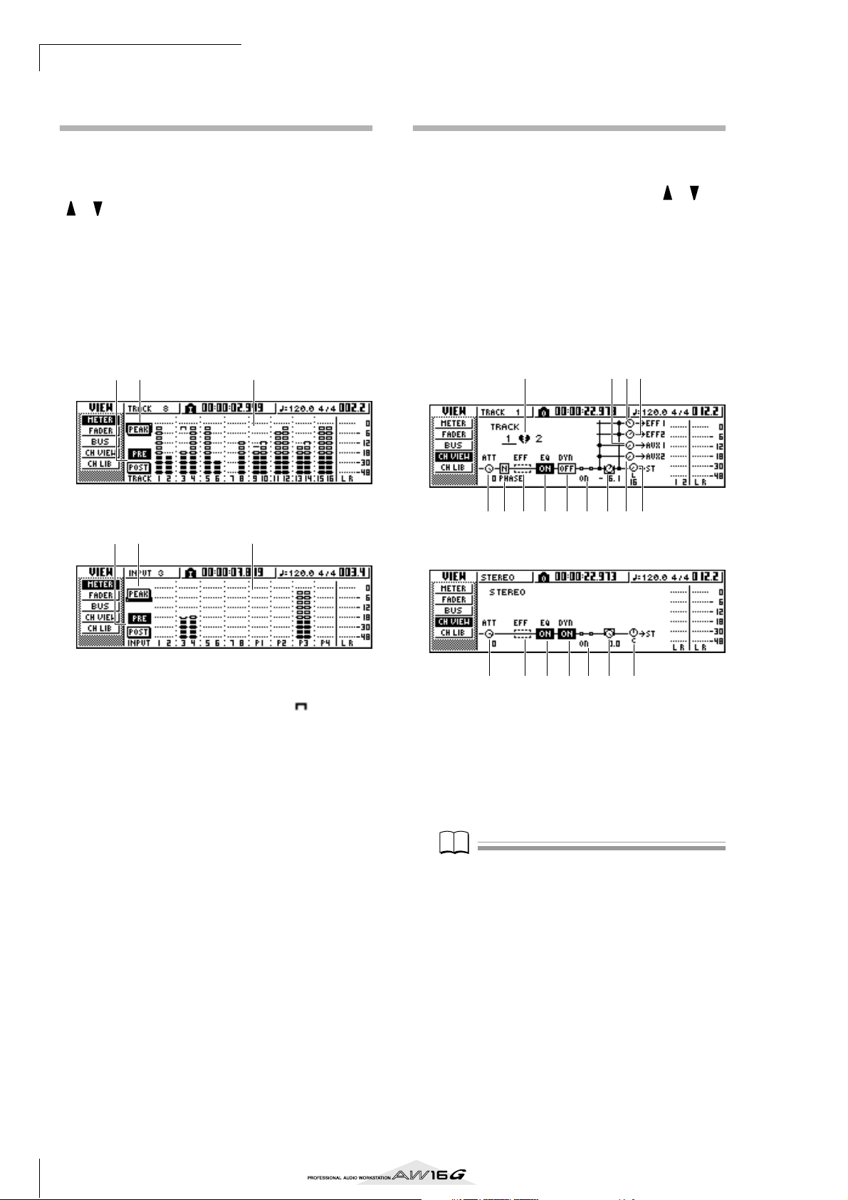
Mixdown and bounce operations
Note
Using meters to check the level of each channel
During mixdown or bouncing, you can watch meters
that indicate the input levels in a single screen. To do so,
repeatedly press the Selected Channel section [VIEW]
key or hold down the [VIEW] key and use the CURSOR
[ ]/[ ] keys to access the METER page of the VIEW
screen.
In the METER page, the display will change depending
on the channel that is currently selected (shown in the
upper left of the screen). Press an [INPUT SEL] key to
view the meters for the input channels/pad channels, or
press a [TRACK SEL] key to view the meters for the track
channels.
● If a track channel is selected
1 32
Viewing all parameters for a certain channel
Sometimes you will want to see all mix parameters for a
certain channel in a single screen. To do this, repeatedly
press the Selected Channel section [VIEW] key or hold
down the [VIEW] key and use the CURSOR [ ]/[ ]
keys to access the CH VIEW page of the VIEW screen.
(Some items can also be edited from this page.)
The display in the CH VIEW page will change depending
on the currently selected channel (shown in the upper
left of the screen). Use the [INPUT SEL] keys, pads 1–4,
[TRACK SEL] keys, and [STEREO SEL] key to select the
channel that you want to view.
● If an input channel, pad channel, or track channel is
selected
1
89J
● If an input channel/pad channel is selected
1 32
1 PEAK button
This button switches the level meter peak hold function on/off. When this button is on, a indicator
will show the peaks of the level meters, and this
indicator will be held. To reset the indicator, temporarily turn off the PEAK button. This setting is shared
with the BUS page of the VIEW screen.
B PRE/POST buttons
These buttons select whether the level meters in the
METER page will indicate the pre-fader levels (PRE)
or the post-fader levels (POST). This setting is independent from the BUS page of the VIEW screen.
C Level meters
These indicate the input level of each channel.
2 3 4 5 6 M K L7
● If the stereo output channel is selected
2 4 5 6 N7 L
1 Pairing
Indicates the pairing status of adjacent odd-numbered/even-numbered channels. Paired channels
are indicated by a heart-shaped symbol, and
unpaired channels are indicated by a broken heart.
Move the cursor here and press the [ENTER] key to
switch pairing on/off.
Note
Pairing cannot be switched off for track channels 9/10–
15/16, pad channels 1–4, and the stereo channel.
B ATT knob
Move the cursor to this knob and turn the [DATA/
JOG] dial to adjust the attenuation of the signal over
a range of 0 to –96 dB before it enters the EQ. This
is the same function as the ATT. knob in the EDIT
page of the EQ screen.
C Phase (except for the stereo output chan-
nel)
Move the cursor here and press the [ENTER] key to
switch the phase of the signal between N (Normal)
and R (Reverse).
90
Page 91

D Effect insert
Note
Note
This lets you insert an internal effect into the channel. When you move the cursor here and press the
[ENTER] key, a popup window will appear, allowing you to select internal effect 1 or 2.
E EQ
Move the cursor here and press the [ENTER] key to
switch EQ on/off.
F DYN
Move the cursor here and press the [ENTER] key to
switch dynamics on/off.
G ON/OFF
Move the cursor here and press the [ENTER] key to
switch the channel on/off.
H EFF1 (except for the stereo output channel)
I EFF2 (except for the stereo output channel)
J AUX1 (except for the stereo output chan-
nel)
K AUX2 (except for the stereo output chan-
nel)
Move the cursor to these knobs and turn the [DATA/
JOG] dial to adjust the send levels to effect buses 1/
2 and AUX buses 1/2.
By moving the cursor to the left of the knob and
pressing the [ENTER] key, you can switch between
pre-fader (send the pre-fader signal to the bus) and
post-fader (send the post-fader signal to the bus).
L PAN/BALANCE knob
Move the cursor to this knob and turn the [DATA/
JOG] dial to adjust the pan (or balance, in the case
of the stereo output channel) of the signal that is
sent from the channel to the stereo bus or L/R bus.
M FADER knob (except for the stereo output
channel)
Move the cursor to this knob and turn the [DATA/
JOG] dial to adjust the level of the signal that is sent
from the channel to the stereo bus or L/R bus. The
range is –∞ to +6 dB.
Note
The FADER knob of a track channel will follow the operation of the corresponding panel fader 1–8 or 9/10–15/16.
However, please note that if you adjust an on-screen
knob and then operate the panel fader, the value will not
change until the fader passes the current value.
Phase no change no change no change
Attenuation 0 dB 0 dB 0 dB
EQ ON ON ON
EQ parameters flat flat flat
Dynamics on/off OFF OFF OFF
Dynamics type COMP COMP COMP
Dynamics
parameters
Pan
Fader 0 dB
* If FADER FLIP is set to TRACK in the UTILITY screen PREFER page.
no effect no effect no effect
If paired: L channel = L16,
R channel = R16
If unpaired: center
N OUTPUT LEVEL (only for the stereo output
channel)
Move the cursor to this knob and turn the [DATA/
JOG] dial to adjust the output level of the signal that
is sent from the stereo output channel to the STEREO/AUX OUT jacks and MONITOR OUT jacks.
The range is –∞ to 0 dB.
Note
The OUTPUT LEVEL knob will follow the operation of
the panel [STEREO FADER]. However, please note that if
you adjust the on-screen knob and then operate the panel
fader, the value will not change until the fader passes the
current value.
Initializing a channel
The mix parameters (EQ, dynamics, pan, etc.) of a channel can be reset to their default settings in a single operation. This function lets you start mixdown or bounce
operations with the track channels “zeroed,” and provides an easy way to reset the levels back to the nominal
setting if you can no longer hear any sound.
In the Quick Navigate section, repeatedly
1
press the [MONITOR] key or hold down the
[MONITOR] key and use the CURSOR [ ]/
[] keys to access the INIT page.
In this page you can separately initialize the mix
parameters of input channels 1–8, pad channels 1–
4, or track channels 1–16.
Press the [INPUT SEL] key, pad, or [TRACK
2
SEL] key for the channel that you want to initialize.
When you press a key or pad, the upper line of the
screen will indicate “CH.PARAMETER INITIALIZED,” and the corresponding channel will be initialized. (Channel library 00 will be recalled.)
An initialized channel will have the following mix
parameter settings.
Input channel Pad channel Track channel
L channel = L16
R channel = R16
*
0 dB no change
If paired: L channel = L16,
R channel = R16
If unpaired: center
*
9
Mixdown and bounce operations
91
Page 92

Mixdown and bounce operations
Tip!
Editing the EQ parameters
The chapters entitled “Track recording” and “Overdubbing” explained how to load an EQ library and use the
Selected Channel section [EQ] knob to make adjustments. Here’s how you can make more detailed adjustments to the EQ parameters.
Press an [INPUT SEL] key, a pad 1–4, a
1
[TRACK SEL] key, or the [STEREO SEL] key to
select the channel whose EQ you want to
adjust.
If desired, load library data from the EQ
2
library.
Repeatedly press the Selected Channel sec-
3
tion [EQ] knob or hold down the [EQ] knob
and use the CURSOR [ ]/[ ] keys to access
the EDIT page of the EQ screen.
The EDIT page of the EQ screen lets you edit all of
the EQ parameters.
2 4 536
81
7
1 ON/OFF button
Switches the EQ on/off.
B Response curve
Graphically indicates the approximate response of
the EQ.
C FLAT button
Move the cursor to this button and press the
[ENTER] key to reset the boost/cut amount of all
bands to 0 dB.
D ATT. (Attenuation) knob
Attenuates the signal immediately before it is input
to the EQ, over a range of –96 to 0 dB. This is used
mainly to prevent the signal from clipping when
you use the EQ to boost a specific frequency region.
E Output meter
Indicates the level of the signal after it has passed
through the EQ.
F Q knobs
Specify the Q (steepness) at which each band
(HIGH, HI-MID, LO-MID, LOW) will be boosted or
cut. The range is 10–0.10, and higher settings will
produce a steeper curve.
G F (Frequency) knobs
Specify the center frequency of the boost/cut, over a
range of 21.2 Hz–20.0 kHz.
H G (Gain) knobs
Specify the amount of boost/cut, over a range of
–18.0 dB to +18.0 dB.
Move the cursor to the parameter that you
4
want to edit, and use the [DATA/JOG] dial to
adjust the value.
To switch the LOW band type, move the cur-
5
sor to the LOW band Q knob and turn the
[DATA/JOG] dial toward the left.
With the default EQ settings, the LOW band is a
shelving type. (The value field for the Q knob will
indicate “L.SHL”.)
If you turn the Q knob toward the left, the Q knob
value field will change to a numerical value, and
will switch to the same boost/cut type as the HIMID and LO-MID bands.
If you continue turning the Q knob toward the left,
the Q knob value field will indicate “HPF,” and the
LOW band will function as a high-pass filter. If
“HPF” is selected, you can use the LOW band G
knob to switch the high-pass filter on/off.
To switch the HIGH band type, turn the
6
HIGH band Q knob all the way to the left.
With the default EQ settings, the HIGH band is a
shelving type. (The value field for the Q knob will
indicate “H.SHL”.)
If you turn the Q knob toward the left, the Q knob
value field will change to a numerical value, and
will switch to the same boost/cut type as the HIMID and LO-MID bands.
If you continue turning the Q knob toward the left,
the Q knob value field will indicate “LPF,” and the
HIGH band will function as a low-pass filter. If
“LPF” is selected, you can use the HIGH band G
knob to switch the low-pass filter on/off.
To switch the EQ on/off, press the [ENTER]
7
key.
In the EDIT page, you can press the [ENTER] key to
switch the EQ on/off (except when the cursor is
located at the FLAT button).
Tip!
• If the meter display clips because you boosted a certain
band, lower the ATT. knob to attenuate the signal.
• The [EQ] knob of the Selected Channel section will still
operate even while the EDIT page of the EQ screen is
displayed.
92
Page 93
Editing the dynamics parameters
Note
Note
Tip!
You can perform detailed editing of the dynamics parameters in the same way as for the EQ parameters.
Press an [INPUT SEL] key, a pad 1–4, a
1
[TRACK SEL] key, or the [STEREO SEL] key to
select the channel whose dynamics parameters you want to edit.
From the dynamics library, recall the settings
2
that are closest to what you have in mind.
Repeatedly press the Selected Channel sec-
3
tion [DYN] knob or hold down the [DYN]
knob and use the CURSOR [ ]/[ ] keys to
access the EDIT page of the DYN screen.
2 4
1 3 7 56
1 ON/OFF button
Switches dynamics on/off.
B TYPE
Indicates the currently selected dynamics type. The
displayed indication has the following meaning.
COMP........................ Compressor
EXPAND..................... Expander
GATE.......................... Gate
COMPAND-H............ Compander (hard)
COMPAND-S............. Compander (soft)
DUCKING ................. Ducking
Note
You will not be able to select LEFT if you have selected
input channel 1, pad channel 1, track channel 1, or the
stereo output channel.
Tip!
Dynamics settings and operation are linked for paired
channels and for the stereo output channel. In this case,
dynamics processing will operate simultaneously for both
channels if either channel exceeds the threshold level.
E GR (Gain Reduction)
Indicates the amount of gain reduction produced by
the dynamics processor, in a range of –18 dB to
0 dB.
F Output meter
Indicates the level of the signal after it has passed
through the dynamics processor.
G Parameters
Here you can edit the parameters of the dynamics
processor. The type of parameters and their ranges
will differ depending on the dynamics processor
type. For details on the types of parameter and their
function, refer to the appendix.
Move the cursor to the parameter that you
4
want to edit, and use the [DATA/JOG] dial to
edit the value.
To switch dynamics on/off, press the [ENTER]
5
key.
In the EDIT page, you can press the [ENTER] key to
switch dynamics on/off regardless of the cursor
location.
Please be aware that if you edit even one parameter
in the EDIT page of the DYN screen, the operation
of the Selected Channel section [DYN] knob will
change as follows for that channel.
9
Mixdown and bounce operations
Note
You cannot change the dynamics type in this page. If you
want to use a different type, you must recall library settings that use the desired type.
C Response curve
This graph indicates the approximate response of
dynamics settings. The horizontal axis of the graph
is the input level, and the vertical axis is the output
level.
D KEYIN SOURCE
Selects one of the following as the trigger signal
(key-in signal) that will control dynamics processing.
SELF ........................... The post-EQ signal of the currently
selected channel
LEFT ........................... The post-EQ signal of the adjacent
channel to the left
AUX1 ......................... The signal immediately before the
master send level of the AUX 1 bus
AUX2 ......................... The signal immediately before the
master send level of the AUX 2 bus
93
Page 94
Mixdown and bounce operations
Note
1 Immediately after recalling a read-only library
that contains dynamics settings, turning the
[DYN] knob will simultaneously adjust multiple parameters to affect the dynamics processing. (The amount of change will depend
on the last-recalled library.)
Editing the parameters of an internal effect
By using the EDIT page of the EFF1 screen or EFF2
screen, you can make detailed edits to the effect parameters of the internal effects 1 and 2.
If an effect is internally connected via send/return in the
mixer section, the parameters (EQ, pan, AUX send, etc.)
of the return channel that processes the return signal can
also be edited in this page.
As an example, here’s how you can edit the settings of
internal effect 1, internally connected via send/return.
For internal effect 1, recall an effect library
1
that uses the desired effect type.
You cannot change the effect type (e.g., reverb,
delay) in the EDIT page. You must first recall library
settings that use the desired type.
In the Selected Channel section, repeatedly
2
press the [EFF1] knob or hold down the
[EFF1] knob and use the CURSOR [ ]/[ ]
keys to access the EDIT page of the EFF1
screen.
The EDIT page lets you edit all of the effect parameters.
B For a channel for which you edited even one
parameter in the EDIT page of the DYN
screen, turning the [DYN] knob will adjust
only the last-edited parameter. (The lastedited parameter is remembered for each
channel.)
C If you once again recall a read-only library
that contains dynamics settings, turning the
[DYN] knob will again simultaneously adjust
multiple parameters.
2 3 4
1 5
1 BYPASS ON/OFF button
Switches effect bypass on/off. The effect will not be
heard if this button is on.
B TYPE
Indicates the type of the currently selected effect.
Note
You cannot change the effect type in this page. If you
want to use a different type, you must recall library settings that use the desired effect type.
C STEREO/MONO
Indicates whether the effect is stereo or monaural. A
stereo-input effect is indicated by , and a monaural-input effect is indicated by .
D USED AS
Indicates how this effect is being used. If the effect
is internally connected to the mixer section via
send/return, this will indicate “EFF1” or “EFF2.” If
the effect is inserted into a specific channel, this
will indicate the name of the channel into which
the effect is inserted (e.g., “INPUT 1”).
94
Page 95

E Parameter page/Return channel page
Tip!
Note
In this area you can edit the various effect parameters. The content and range of the parameters will
depend on the currently-used effect type.
If the effect is internally connected to the mixer section via send/return, this area will show the mix
parameters of the return channel, allowing you to
edit them.
Move the cursor to the effect parameter that
3
you want to edit, and turn the [DATA/JOG]
dial to edit the value.
Depending on the effect type, this area may be used
to show multiple parameter pages. In this case,
repeatedly press the CURSOR [ ] key to access
the parameter page that contains the parameter you
want to edit.
For example, the illustration below shows the
parameter pages for the STEREO DELAY effect type.
1 EFF2SEND
Adjusts the level at which the signal is sent from the
return channel to the other internal effect.
Note
You cannot send the signal from return channel 1 to
insert effect 1 (since this would mean sending the signal
back to the same effect itself). For this reason, the EDIT
page of the EFF1 screen has no send level to effect 1. For
the same reason, the EDIT page of the EFF2 screen has no
send level to effect 2.
B AUX1SEND
C AUX2SEND
These adjust the send level of the signal that is sent
from the return channel to AUX buses 1/2.
D EFF2 PRE/POST
Switches the signal that is sent from the return channel to the other effect bus between pre-fader and
post-fader.
E AUX1 PRE/POST
F AUX2 PRE/POST
These switch the signals that are sent from the
return channel to AUX buses 1/2 between pre-fader
and post-fader.
MIX BAL. parameter
Tip!
The parameter pages show the parameters that are specific to that effect type. However for all effect types, the
lower right of the last parameter page will have a MIX
BAL. parameter which sets the mix balance between the
effect sound and the original sound.
To edit the mix parameters of the return
4
channel, access the last parameter page, and
then press the CURSOR [ ] key once again.
If the effect is internally connected to the mixer section via send/return, you can repeatedly press the
CURSOR [ ] key to access the mix parameters of
the return channel. The following pages are the
same for all effect types.
21 3
21 3
9
Mixdown and bounce operations
4 5 6
1 EQ HIGH GAIN
B EQ HIGH FREQ
C EQ HIGH Q
D EQ H-MID GAIN
E EQ H-MID FREQ
F EQ H-MID Q
These specify the gain, frequency, and Q for the
HIGH and HI-MID bands of the return channel EQ.
The range of each parameter is the same as in the
EDIT page of the EQ screen.
4 5 6
95
Page 96
Mixdown and bounce operations
Note
Note
Tip!
21 3
4 5 6
1 EQ L-MID GAIN
B EQ L-MID FREQ
C EQ L-MID Q
D EQ LOW GAIN
E EQ LOW FREQ
F EQ LOW Q
These specify the gain, frequency, and Q for the LOMID and LOW bands of the return channel EQ. The
range of each parameter is the same as in the EDIT
page of the EQ screen.
Inserting an effect into a track channel
The chapter “Track recording” explained how to insert an
internal effect into an input channel. In the same way,
you can also insert an effect into a track channel or pad
channel. As an example, here’s how to insert internal
effect 1 into a track channel for use during mixdown or
bouncing.
In the Selected Channel section, repeatedly
1
press the [EFF1] knob or hold down the
[EFF1] knob and use the CURSOR [ ]/[ ]
keys to access the SEND page of the EFF1
screen.
Note
If the displayed page is different than shown above, make
sure that a track channel is selected as the object of operations. (This is indicated in the upper left of the screen.)
If an input channel/pad channel is selected, press any one
of the [TRACK SEL] keys.
1 2 3
1 PAN L
B PAN R
Independently specify the return channel panning
for the L and R channels.
C RETURN
Adjusts the input level for return channel 1.
Access the desired return channel page,
5
move the cursor to a parameter, and turn the
[DATA/JOG] dial.
To switch effect bypass on/off, press the
6
[ENTER] key.
In the EDIT page, you can press the [ENTER] key to
switch bypass on/off regardless of the current location.
Move the cursor to the EFF INSERT field of
2
the track channel into which you want to
insert an effect, and press the [ENTER] key.
A popup window will appear, asking whether it is
ok to release internal effect 1 from the send/return
connection.
Move the cursor to the OK button and press
3
the [ENTER] key.
Internal effect 1 will be inserted into the
4
selected track channel.
Press the [EFF1] knob twice to access the
5
LIBRARY page of the EFF1 screen.
Select the library that you want to use for
6
that channel.
Note
If you insert an internal effect into a channel, the SEND
page of the EFF1 screen will no longer show return channel pages 1–4. To adjust the balance between the original
sound and the effect sound, use the MIX BAL. parameter
that is shown in the last parameter page.
96
Tip!
You can also insert an effect by using the effect insert
field in the CH VIEW page of the VIEW screen (→ p. 91).
Page 97
Chapter 10
Note
Creating an audio CD
This chapter explains how you can use the CD-RW drive to create an
audio CD, and how to play back an audio CD.
Creating an audio CD
On the AW16G, you can select one or more songs on the
hard disk, and write the audio data from the stereo track
of each song to a CD-R/RW disc in CD-DA format. The
CD-R/RW media to which you write this data can be
played by the CD-RW drive or a conventional CD player
in the same way as any audio CD.
Note
Some CD players that do not support CD-R/RW media
may not be able to play back a CD you create.
In order to create a CD, you must first register one or
more songs in a “track list,” and then write the virtual
track currently selected for the stereo track of each song
(the “current track”) to the CD in the order specified by
the track list.
A maximum of 99 tracks (areas on CD media to which
audio data can be written individually) can be written to
one volume of CD-R/RW media, and each track must be
at least four seconds long. The maximum length of time
that can be written is approximately 74 minutes for
650 MB media, or approximately 80 minutes for 700 MB
media.
Types of media that you can use with the
CD-RW drive
The CD-RW drive of the AW16G can use two types of
media: “CD-R” which lets you record and add data, and
“CD-RW” which lets you erase previously-recorded data
and rewrite it. Each type of media has the following characteristics.
● CD-R
You can write data to this media, and add additional
data later. You cannot erase and rewrite data that has
already been written. Once you perform a process
known as “finalizing the disc,” the audio data written
to the CD-R can be played by the CD-RW drive or by
most CD players.
● CD-RW
In addition to writing and adding data, this media lets
you erase all recorded data and rewrite it. Audio data
written to a CD-RW can be played back by the CDRW or by CD players that support CD-RW media.
97
Page 98
Creating an audio CD
Note
A
Methods of writing an audio CD
There are two ways in which you can write audio data to
CD-R/RW media.
● Track At Once
This method writes the data in units of CD tracks. The
advantage of this method is that you can add new
data to media that already contains existing data.
With the Track At Once method, the data from the
beginning to the end of the stereo track of a song is
written to the CD as one track. (Even if there is a portion during the song that contains no data, it will be
written as silent audio data.)
Since each track is written individually when you use
this method, an interval of approximately two seconds will be created between each track.
Start
Song A
Song B
Audio CD
Track 1
End
Start End
Track 2
interval (2 seconds)
In order for a disc written using Track At Once to be
playable by the CD-RW drive or a CD player, you
must perform a process known as “finalizing” to
write track information to the disc. Once you have
finalized a disc, you cannot write any more data to it.
● Disc At Once
This method writes all tracks at once. Similarly to
when using the Track At Once method, the data from
the beginning to the end of the stereo track of each
song is written to the CD as one track.
However since writing does not stop until all data
has been written, there will be no gap between the
tracks.
Start
Song A
Marker = off
Song B
Marker = off
Audio CD
Track 1
no gap
End
Start End
Track 2
When using Disc At Once to write a CD, you can use
the start point, end point and markers that were
assigned within the AW16G song to divide a single
continuous song into multiple tracks for writing.
For example, this is convenient when you have
recorded a live performance as a single song, and
want to assign track numbers while leaving the playback in continuous form.
Start
Song A
Marker = on
End
2
Start End1 2
Song B
Marker = off
udio CD
Track 1
Track 21Track 3
Track 4
Note
•A track shorter than four seconds cannot be written to
an audio CD. If you use start point/end point/markers
to divide a song into multiple tracks, make sure that
each track is at least four seconds long.
• If the length of the stereo track exceeds the writable
length of the media, you can create an audio CD by
adjusting the start point/end point so that the region is
within the allowable length. (
Media that you write using Disc At Once will be
finalized automatically, and can be played back by a
CD-RW drive or CD player that supports that type of
media. However, no further data can be written to a
disc that was written using Disc At Once.
→
p. 102)
98
Page 99
Basic settings for the CD-RW drive
Note
Before you actually write data to a CD, you will need to
make basic settings for the CD-RW drive.
In the Work Navigate section, repeatedly
1
press the [CD] key or hold down the [CD]
key and use the CURSOR [ ]/[ ] keys to
access the SETTING page of the CD screen.
621
5 8 734
1 CD-RW MEDIA ERASE
Erases the data that was written to CD-RW media.
For details, refer to “Erasing CD-RW media” (→
p. 105).
B AUDIO WRITE SPEED
Selects the speed at which audio data will be written to CD-R/RW media.
C TEST button
Specifies whether a writing test will be performed
when you execute writing.
D WRITE button
Specifies whether the actual writing operation will
be performed.
E UNDERRUN PROTECT button
Enables/disables the function that prevents buffer
underrun (an error that can occur when data transfer cannot keep up with writing speed).
F DATA WRITE SPEED
This indicates the speed at which data other than
CD audio (e.g., backup data or WAV files) is written
to CD-R/RW media. Normally this will indicate x8.
This will indicate x4 if the media supports a maximum writing speed of x4. This field is for display
only, and cannot be edited.
G COMPARE button
If this button is on, the original data will be compared with the backed-up data or the exported
WAV file after a backup or export operation is performed, to check whether any errors occurred while
writing the data.
H MOTOR ON ACCESS/DISC IN button
Selects one of the following two choices to specify
how the drive will operate when CD-R/RW media is
inserted.
ACCESS...................... The drive will spin only when
access is required.
DISC IN ..................... The drive will spin whenever
media is inserted.
Move the cursor to the AUDIO WRITE SPEED
2
field, and turn the [DATA/JOG] dial to select
the writing speed.
You can select either x8 (eight times as fast as audio
playback) or x4 (four times as fast as audio playback). Normally you should use x8, and drop down
to x4 if errors occur during writing.
Use the TEST button and WRITE button to
3
select the writing operation(s).
The TEST button and WRITE button specify whether
a writing test and/or the actual writing operation
will be performed. The combination of buttons that
are on will determine the operation(s) that will
occur, as follows.
Only the TEST button on .........Only a writing test will be
performed.
Only the WRITE button on......Writing will occur imme-
diately.
Both the WRITE button and
TEST button on...........First a writing test will be per-
formed, and then the actual writing
will be performed.
Depending on the media and the state of the hard
disk, it is possible that an error may occur while the
data is being written. (If you are using a CD-R, this
will make the media unusable.) Thus, you can turn
on the TEST button to check whether an error will
occur before you actually write the disc. If an error
occurs during the test, halt the procedure, and
either lower the writing speed or set the UNDERRUN PROTECT button to ENABLE.
If desired, set the UNDERRUN PROTECT but-
4
ton to ENABLE.
The CD-RW drive of the AW16G has a function to
prevent “buffer underrun” errors which can occur if
data transfer cannot keep up with the writing speed.
If you switch the UNDERRUN PROTECT button to
the “ENABLE” setting, this function will be enabled,
and buffer underruns will be prevented.
Note
If this button is set to ENABLE, the TEST button will automatically be turned off. Also, if the TEST button is turned
on, this button will automatically be set to DISABLE.
10
Creating an audio CD
99
Page 100

Creating an audio CD
Tip!
Writing audio data (Track At Once)
Here’s how to use the Track At Once method to write stereo tracks from songs saved on the hard disk to CD-R/RW
media. Use this method if you expect to be adding tracks
to the disc later, or if you want a two-second gap
between tracks.
Make sure that the appropriate virtual track is
1
selected for the stereo track of the song(s)
you want to write.
Only the virtual track that can be played by the stereo track (i.e., the “current track”) will be written to
disc. If the correct virtual track is not selected, load
that song, use the ST.TRACK page of the MONITOR
screen to switch to the correct virtual track, and
then save the song.
Repeatedly press the [CD] key or hold down
2
the [CD] key and use the CURSOR [ ]/[ ]
keys to access the CD WRITE page of the CD
screen.
Immediately after you access this page, the
following two buttons will appear in the display.
1 2
1 TRACK AT ONCE button
Creates an audio CD using the Track At Once
method.
B DISC AT ONCE button
Creates an audio CD using the Disc At Once
method.
Insert CD-R/RW media in the drive, move the
3
cursor to the TRACK AT ONCE button, and
press the [ENTER] key.
A display like the following will appear.
3 1
6 5 42
1 Song list
This is a list of the songs containing stereo tracks
that will be written to the CD-R/RW media. The line
enclosed by a dotted frame is currently selected for
operations. If no songs have been registered, this
will indicate “-NO TRACK-”.
If audio data has already been written to the
inserted CD-R/RW media but the media has not yet
been finalized, a title of “--EXIST--” will be displayed for the already-written data.
B FINALIZE button
Finalizes the inserted media by writing track information to it.
C INS button
Inserts a new song in front of the song currently
selected in the list.
D NEW button
Adds a song at the end of the song list.
E DEL button
Deletes the selected song from the list.
F EXECUTE button
Executes writing to the CD media.
100
Tip!
If you have inserted CD-RW media that contains data
written using other than the Track At Once method, a
popup window will appear immediately after step 3, asking whether you want to erase the data. If you want to
erase the entire media, move the cursor to the OK button. If you want to cancel creation of an audio CD, move
the cursor to the CANCEL button. Then press the
[ENTER] key.
Move the cursor to the NEW button, and
4
press the [ENTER] key.
The song list will show information (track number/
song name/size of the stereo track) for the song that
will be written to track 1 of the CD.
 Loading...