


YZFR6V(C)
SERVICE MANUAL
LIT-11616-19-78 2C0-28197-10

EAS20050
©2005 by Yamaha Motor Corporation, U.S.A.
YZFR6V(C)
SERVICE MANUAL
First edition, December 2005
All rights reserved.
Any reproduction or unauthorized use
without the written permission of
Yamaha Motor Corporation, U.S.A.
is expressly prohibited.
Printed in U.S.A.
P/N LIT-11616-19-78

EAS20070
NOTICE
This manual was produced by the Yamaha Motor Company, Ltd. primarily for use by Yamaha dealers
and their qualified mechanics. It is not possible to include all the knowledge of a mechanic in one manual. Therefore, anyone who uses this book to perform maintenance and repairs on Yamaha vehicles
should have a basic understanding of mechanics and the techniques to repair these types of vehicles.
Repair and maintenance work attempted by anyone without this knowledge is likely to render the vehicle unsafe and unfit for use.
This model has been designed and manufactured to perform within certain specifications in regard to
performance and emissions. Proper service with the correct tools is necessary to ensure that the vehicle will operate as designed. If there is any question about a service procedure, it is imperative that you
contact a Yamaha dealer for any service information changes that apply to this model. This policy is
intended to provide the customer with the most satisfaction from his vehicle and to conform to federal
environmental quality objectives.
Yamaha Motor Company, Ltd. is continually striving to improve all of its models. Modifications and significant changes in specifications or procedures will be forwarded to all authorized Yamaha dealers and
will appear in future editions of this manual where applicable.
NOTE:
• This Service Manual contains information regarding periodic maintenance to the emission control system. Please read this material carefully.
• Designs and specifications are subject to change without notice.
EAS20080
IMPORTANT MANUAL INFORMATION
Particularly important information is distinguished in this manual by the following.
The Safety Alert Symbol means ATTENTION! BECOME ALERT! YOUR
SAFETY IS INVOLVED!
Failure to follow WARNING instructions could result in severe injury or death
WARNING
to the vehicle operator, a bystander or a person checking or repairing the vehicle.
CAUTION:
NOTE:
A CAUTION indicates special precautions that must be taken to avoid damage to the vehicle.
A NOTE provides key information to make procedures easier or clearer.
EAS20090
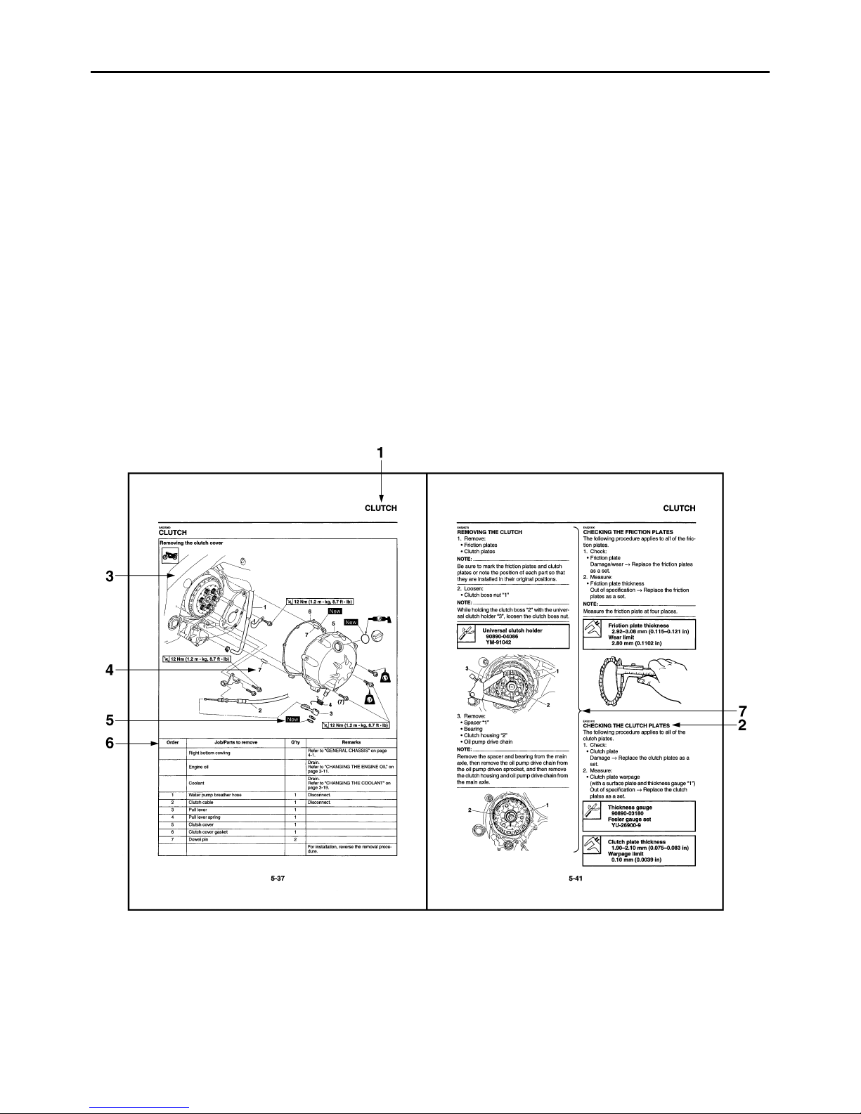
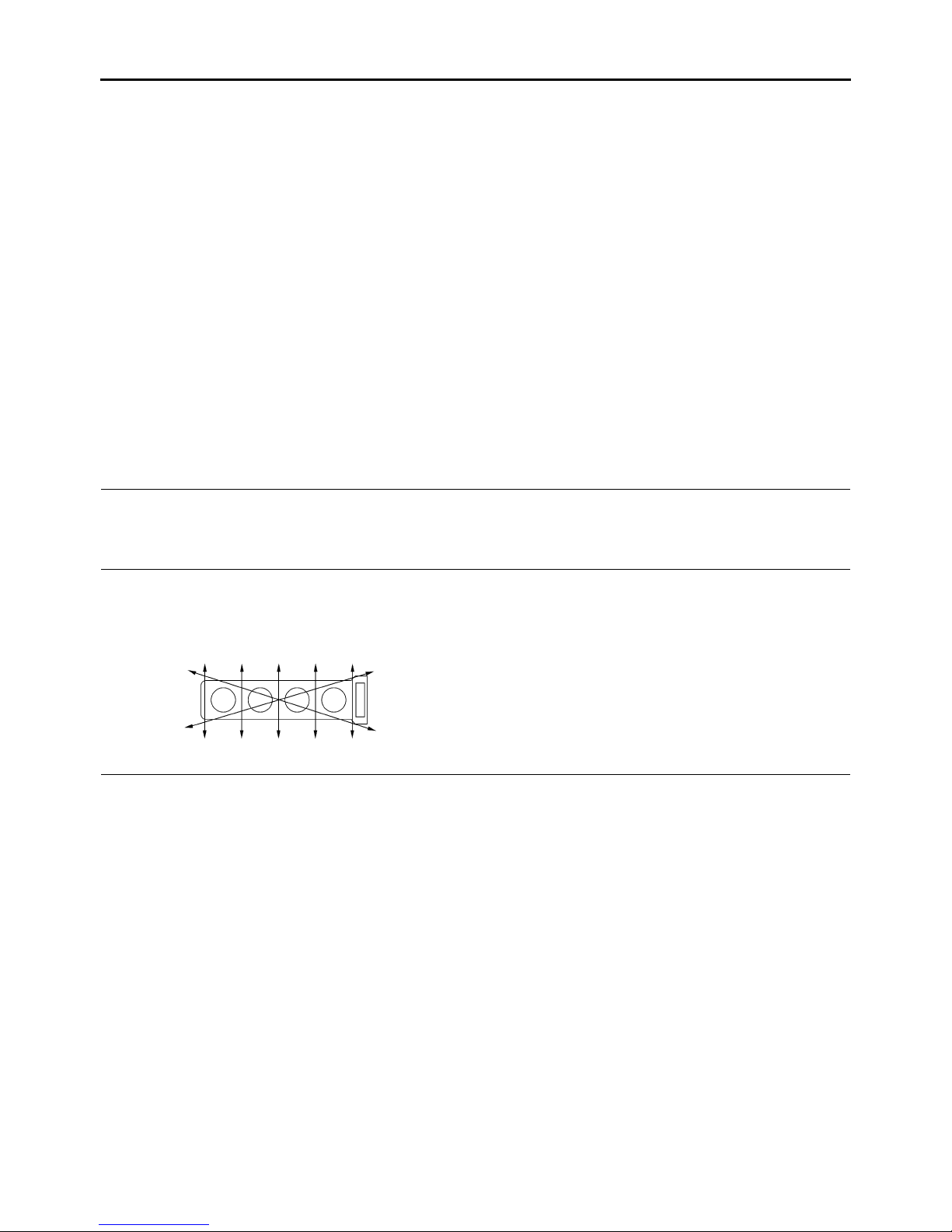
HOW TO USE THIS MANUAL
This manual is intended as a handy, easy-to-read reference book for the mechanic. Comprehensive
explanations of all installation, removal, disassembly, assembly, repair and check procedures are laid
out with the individual steps in sequential order.
• The manual is divided into chapters and each chapter is divided into sections. The current section title
“1” is shown at the top of each page.
• Sub-section titles “2” appear in smaller print than the section title.
• To help identify parts and clarify procedure steps, there are exploded diagrams “3” at the start of each
removal and disassembly section.
• Numbers “4” are given in the order of the jobs in the exploded diagram. A number indicates a disassembly step.
• Symbols “5” indicate parts to be lubricated or replaced.
Refer to “SYMBOLS”.
• A job instruction chart “6” accompanies the exploded diagram, providing the order of jobs, names of
parts, notes in jobs, etc.
• Jobs “7” requiring more information (such as special tools and technical data) are described sequentially.
EAS20100
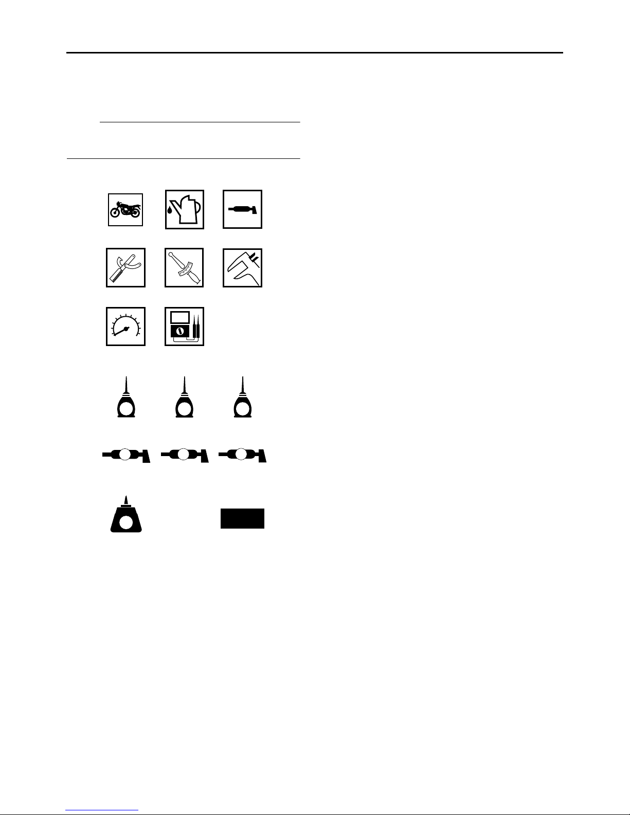
SYMBOLS
The following symbols are used in this manual
for easier understanding.
NOTE:
The following symbols are not relevant to every
vehicle.
123
456
T
.
R
.
78
1. Serviceable with engine mounted
2. Filling fluid
3. Lubricant
4. Special tool
5. Tightening torque
6. Wear limit, clearance
7. Engine speed
8. Electrical data
9. Engine oil
10.Gear oil
11.Molybdenum disulfide oil
12.Wheel bearing grease
13.Lithium-soap-based grease
14.Molybdenum disulfide grease
15.Apply locking agent (LOCTITE
®
16.Replace the part with a new one.
).
91011
E
G
M
12 13 14
B
LS
M
15 16
LT
New

EAS20110
TABLE OF CONTENTS
GENERAL INFORMATION
SPECIFICATIONS
PERIODIC CHECKS AND ADJUSTMENTS
CHASSIS
ENGINE
1
2
3
4
5
COOLING SYSTEM
FUEL SYSTEM
ELECTRICAL SYSTEM
TROUBLESHOOTING
6
7
8
9

GENERAL INFORMATION
IDENTIFICATION ............................................................................................ 1-1
VEHICLE IDENTIFICATION NUMBER..................................................... 1-1
MODEL LABEL ......................................................................................... 1-1
FEATURES ..................................................................................................... 1-2
OUTLINE OF THE FI SYSTEM................................................................. 1-2
FI SYSTEM ............................................................................................... 1-3
YCC-T (Yamaha Chip Controlled Throttle)................................................ 1-4
INSTRUMENT FUNCTIONS..................................................................... 1-7
IMPORTANT INFORMATION ....................................................................... 1-11
PREPARATION FOR REMOVAL AND DISASSEMBLY ........................ 1-11
REPLACEMENT PARTS ........................................................................ 1-11
GASKETS, OIL SEALS AND O-RINGS.................................................. 1-11
LOCK WASHERS/PLATES AND COTTER PINS................................... 1-11
BEARINGS AND OIL SEALS.................................................................. 1-12
CIRCLIPS................................................................................................ 1-12
1
CHECKING THE CONNECTIONS................................................................ 1-13
SPECIAL TOOLS.......................................................................................... 1-14
EAS20130
IDENTIFICATION
EAS20140
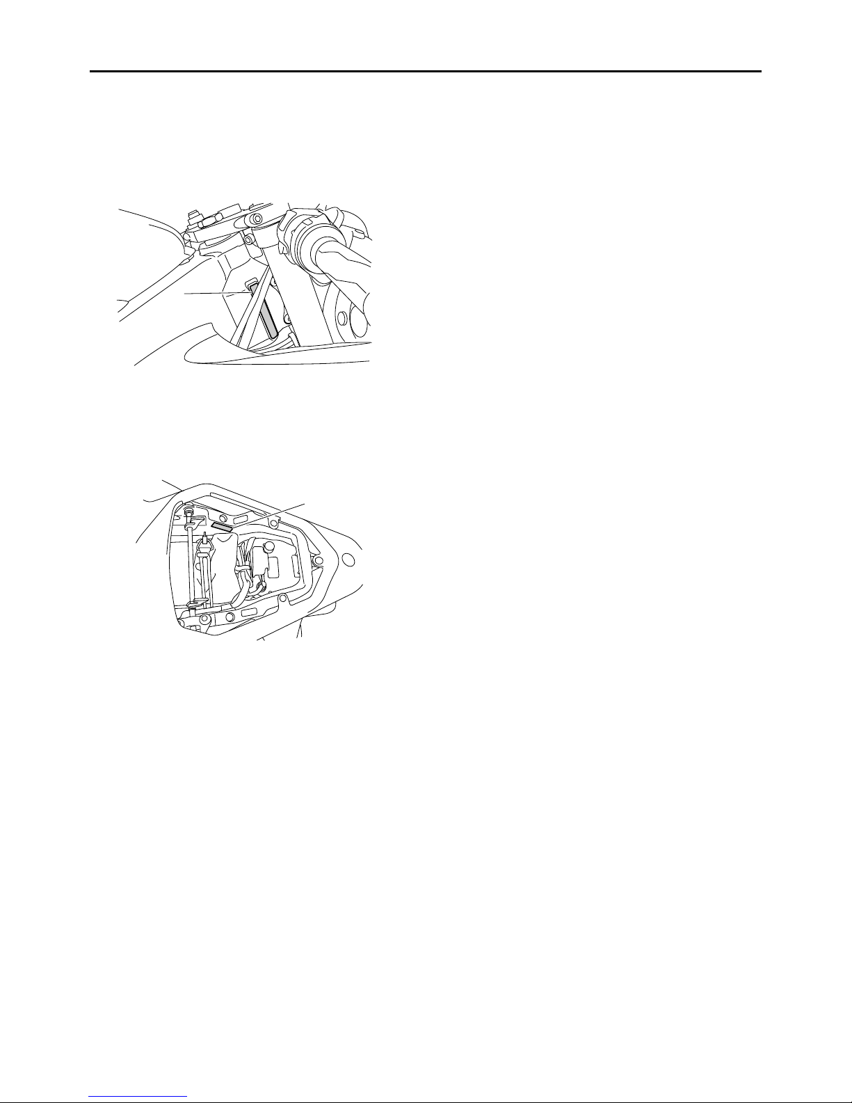
VEHICLE IDENTIFICATION NUMBER
The vehicle identification number “1” is stamped
on the right side of the steering head pipe.
1
EAS20150
MODEL LABEL
The model label “1” is affixed to the frame under
the passenger seat. This information will be
needed to order spare parts.
IDENTIFICATION
1
1-1
FEATURES
EAS20170
FEATURES
ET2C01025
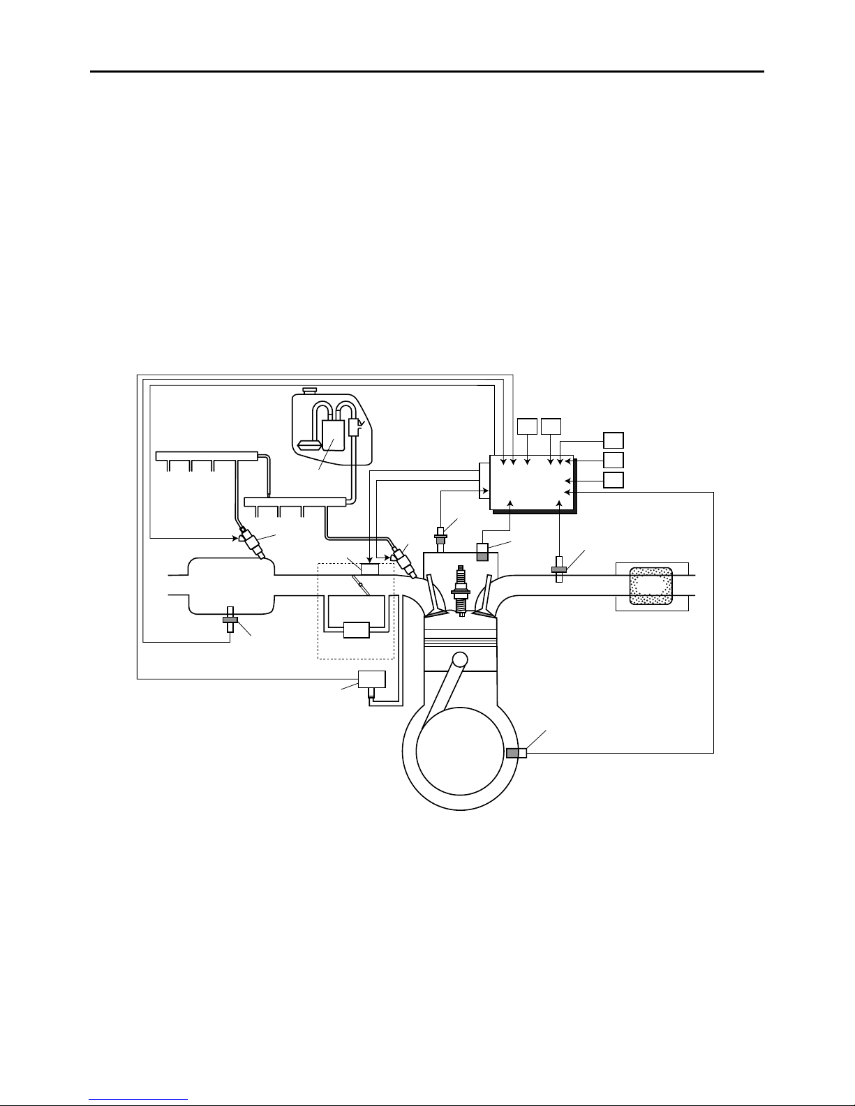
OUTLINE OF THE FI SYSTEM
The main function of a fuel supply system is to provide fuel to the combustion chamber at the optimum
air-fuel ratio in accordance with the engine operating conditions and the atmospheric temperature. In
the conventional carburetor system, the air-fuel ratio of the mixture that is supplied to the combustion
chamber is created by the volume of the intake air and the fuel that is metered by the jet used in the
respective carburetor.
Despite the same volume of intake air, the fuel volume requirement varies by the engine operating conditions, such as acceleration, deceleration, or operating under a heavy load. Carburetors that meter the
fuel through the use of jets have been provided with various auxiliary devices, so that an optimum airfuel ratio can be achieved to accommodate the constant changes in the operating conditions of the engine.
As the requirements for the engine to deliver more performance and cleaner exhaust gases increase,
it becomes necessary to control the air-fuel ratio in a more precise and finely tuned manner. To accommodate this need, this model has adopted an electronically controlled fuel injection (FI) system, in place
of the conventional carburetor system. This system can achieve an optimum air-fuel ratio required by
the engine at all times by using a microprocessor that regulates the fuel injection volume according to
the engine operating conditions detected by various sensors.
The adoption of the FI system has resulted in a highly precise fuel supply, improved engine response,
better fuel economy, and reduced exhaust emissions.
1
22
21
20
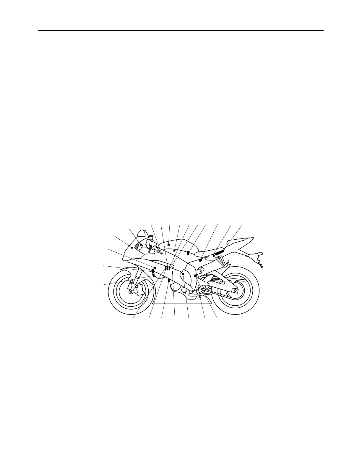
1. Air temperature sensor
2. Engine trouble warning light
3. Air induction system solenoid
4. Throttle servo motor
5. Atmospheric pressure sensor
6. Secondary injectors
7. Primary injectors
8. Intake air pressure sensor
9. Fuel pump
10.Relay unit (fuel pump relay)
11.Lean angle sensor
12.ECU (engine control unit)
13.EXUP servo motor
14.O
sensor
2
2
6 7 83 45 9 11 12
15.Speed sensor
16.Coolant temperature sensor
17.Crankshaft position sensor
18.Throttle position sensor (for throttle cable
19.Throttle position sensor (for throttle valves)
20.Spark plug
21.Ignition coil
22.Cylinder identification sensor
141516171819
pulley)
10
13
1-2
FEATURES
ET2C01019
FI SYSTEM
The fuel pump delivers fuel to the fuel injector via the fuel filter. The pressure regulator maintains the
fuel pressure that is applied to the fuel injector at only 324 kPa (3.24 kg/cm², 46.1 psi). Accordingly,
when the energizing signal from the ECU energizes the fuel injector, the fuel passage opens, causing
the fuel to be injected into the intake manifold only during the time the passage remains open. Therefore, the longer the length of time the fuel injector is energized (injection duration), the greater the volume of fuel that is supplied. Conversely, the shorter the length of time the fuel injector is energized
(injection duration), the lesser the volume of fuel that is supplied.
The injection duration and the injection timing are controlled by the ECU. Signals that are input from the
throttle position sensor (for throttle cable pulley), throttle position sensor (for throttle valves), coolant
temperature sensor, atmospheric pressure sensor, cylinder identification sensor, lean angle sensor,
crankshaft position sensor, intake air pressure sensor, air temperature sensor, speed sensor and O
sensor enable the ECU to determine the injection duration. The injection timing is determined through
the signals from the crankshaft position sensor. As a result, the volume of fuel that is required by the
engine can be supplied at all times in accordance with the driving conditions.
2
#3#1 #2 #4
19
18
A
C
1
2
#3#1 #2 #4
16
13
3
5
4
8
9
10
11
12
B
17
15
14
67
1. Secondary injector
2. Fuel pump
3. Primary injector
4. Cylinder identification sensor
5. ECU (engine control unit)
6. Throttle position sensor (for throttle cable
pulley)
7. Throttle position sensor (for throttle valves)
8. Speed sensor
9. Air temperature sensor
10.Lean angle sensor
11.O
sensor
2
12.Catalytic converter
13.Coolant temperature sensor
14.Crankshaft position sensor
15.Intake air pressure sensor
16.Throttle servo motor
17.Throttle body
18.Atmospheric pressure sensor
19.Air filter case
A. Fuel system
B. Air system
C. Control system
1-3

FEATURES
ET2C01026
YCC-T (Yamaha Chip Controlled Throttle)
Mechanism characteristics
Yamaha developed the YCC-T system employing the most advanced electronic control technologies.
Electronic control throttle systems have been used on automobiles, but Yamaha has developed a faster, more compact system specifically for the needs of a sports motorcycle. The Yamaha-developed
system has a high-speed calculating capacity that produces computations of running conditions every
1/1000th of a second.
The YCC-T system is designed to respond to the throttle action of the rider by having the ECU instantaneously calculate the ideal throttle valve opening and generate signals to operate the motor-driven
throttle valves and thus actively control the intake air volume.
The ECU contains three CPUs with a capacity about five times that of conventional units, making it possible for the system to respond extremely quickly to the slightest adjustments made by the rider. In particular, optimized control of the throttle valve opening provides the optimum volume of intake air for
easy-to-use torque, even in a high-revving engine.
Aims and advantages of using YCC-T
• Increased engine power
By shortening the air intake path, higher engine speed is possible → Increased engine power.
• Improved driveability
Air intake volume is controlled according to the operating conditions → Improved throttle response to
meet engine requirement.
Driving force is controlled at the optimal level according to the transmission gear position and engine
speed → Improved throttle control.
• Engine braking control
Due to the throttle control, optimal engine braking is made possible.
• Simplified idle speed control (ISC) mechanism
The bypass mechanism and ISC actuator are eliminated → A simple mechanism is used to maintain
a steady idle speed.
• Reduced weight
Compared to using a sub-throttle mechanism, weight is reduced.
A
1
5
1. Throttle position sensor (for throttle cable
pulley)
2. Throttle servo motor
3. Throttle position sensor (for throttle valves)
4. Throttle valves
5. Throttle cable pulley with linkage guard
A. To throttle grip
2
3
4
1-4
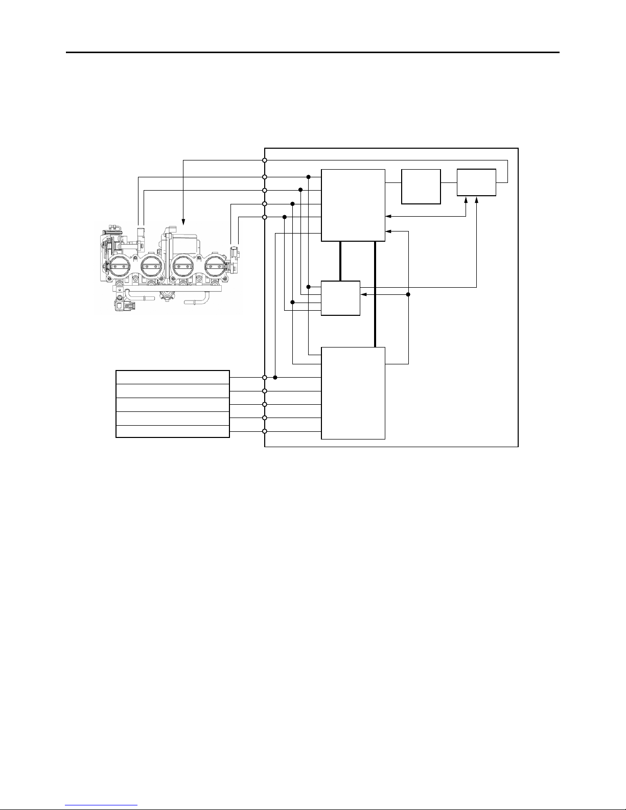
YCC-T system outline
1
2
FEATURES
4
13
8
9
5
10
1
2
3
6
11
12
14
15
7
16
17
18
1. Throttle position sensor (for throttle cable
pulley)
2. Throttle servo motor
3. Throttle position sensor (for throttle valves)
4. ECU (engine control unit)
5. ETV main CPU (32 bit)
6. ETV sub CPU (16 bit)
7. FI CPU (32 bit)
8. Throttle servo motor driver
9. Throttle servo motor driver operation
10.Throttle servo motor driver operation sensing
11.Emergency stop
12.Engine revolution (pulse signal)
13.Sensor input
14.Neutral switch
15.Crankshaft position sensor
16.Speed sensor
17.Coolant temperature sensor
sensing/shut off circuit
feedback/emergency stop
18.Atmospheric pressure sensor
1-5
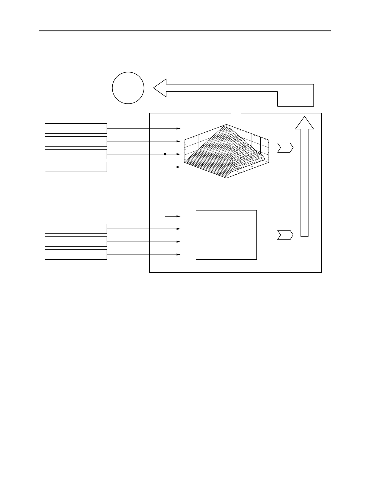
YCC-T control outline
15 M
FEATURES
16
1
2
3
4
8
9
10
11
17
5
6
7
12
13
14
18
19
1. Throttle position sensor (for throttle cable
pulley)
2. Throttle position sensor (for throttle valves)
3. Crankshaft position sensor
4. Speed sensor
5. Coolant temperature sensor
6. Neutral switch
7. Atmospheric pressure sensor
8. Throttle position (for throttle cable pulley) (two
signals)
9. Throttle position (for throttle valves) (two
signals)
10.Engine revolution
11.Vehicle speed
12.Coolant temperature
13.Neutral/In gear
14.Atmospheric pressure
15.Throttle servo motor
16.ECU (engine control unit)
17.Base map
18.Idle speed control
19.Calculated throttle valve opening angle
1-6
FEATURES
ET2C01020
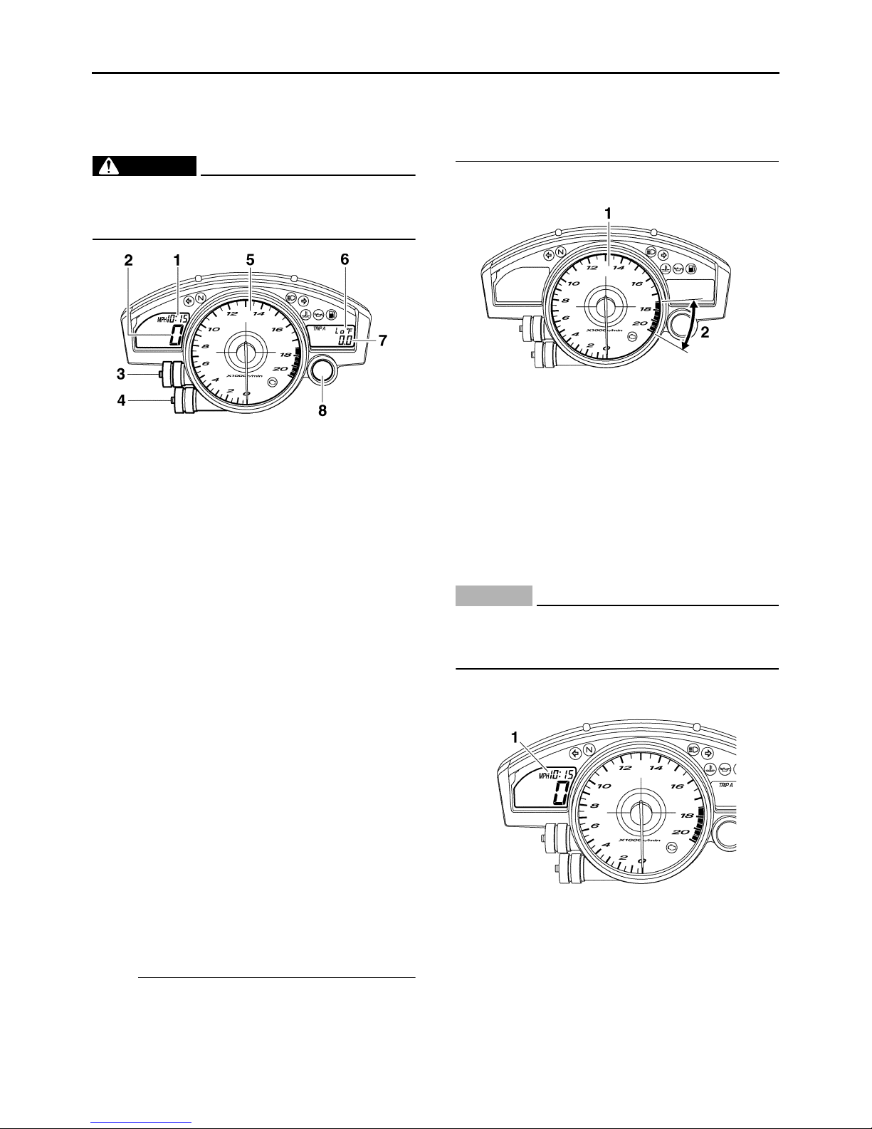
INSTRUMENT FUNCTIONS
Multi-function meter unit
EW2C01003
WARNING
Be sure to stop the vehicle before making
any setting changes to the multi-function
meter unit.
1. Clock
2. Speedometer
3. “SELECT” button
4. “RESET” button
5. Tachometer
6. Coolant temperature display/air intake
temperature display
7. Odometer/tripmeters/fuel reserve
tripmeter/stopwatch
8. Shift timing indicator light
The multi-function meter unit is equipped with
the following:
• a speedometer (which shows the riding speed)
• a tachometer (which shows engine speed)
• an odometer (which shows the total distance
traveled)
• two tripmeters (which show the distance traveled since they were last set to zero)
• a fuel reserve tripmeter (which shows the distance traveled since the fuel level warning light
came on)
• a stopwatch
• a clock
• a coolant temperature display
• an air intake temperature display
• a self-diagnosis device
• a display brightness and shift timing indicator
light control mode
NOTE:
• Be sure to turn the key to “ON” before using the
“SELECT” and “RESET” buttons.
• To switch the speedometer and odometer/trip-
meter displays between kilometers and miles,
press the “SELECT” button for at least one
second.
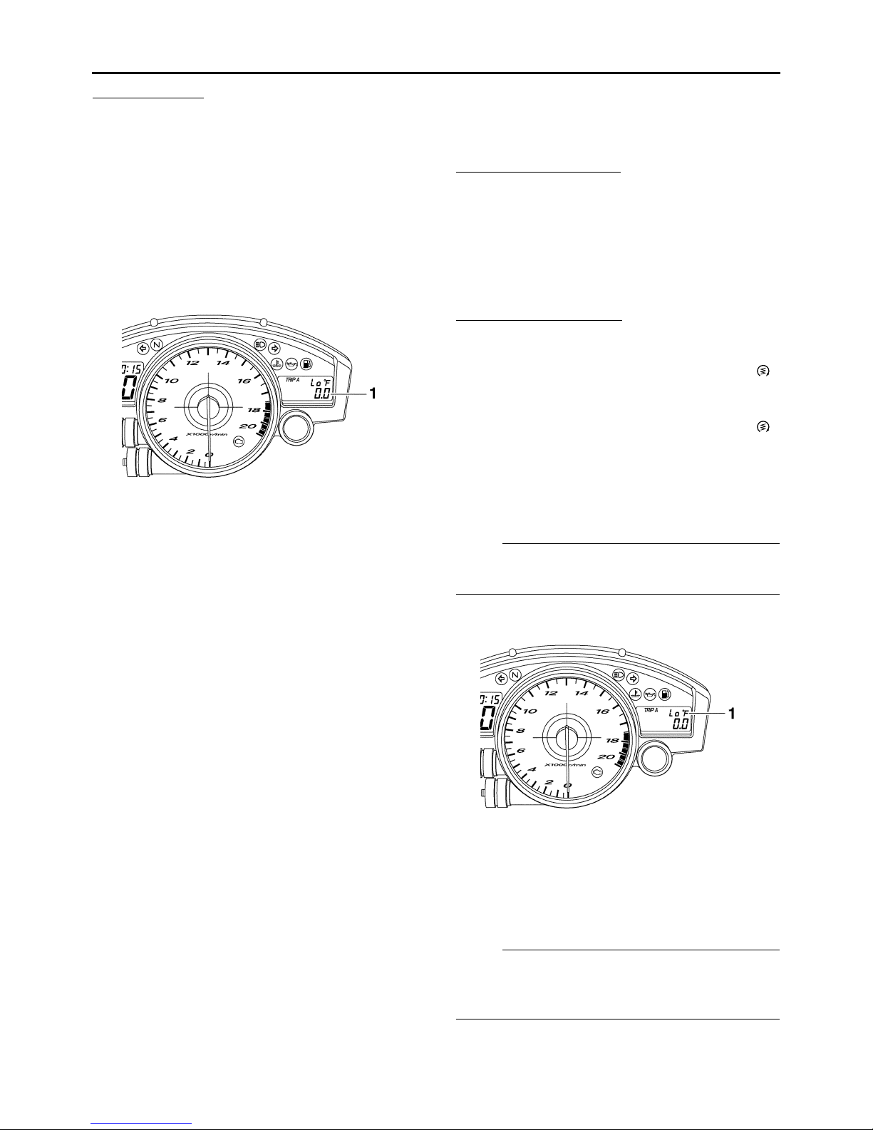
Tachometer
1. Tachometer
2. Tachometer red zone
The electric tachometer allows the rider to monitor the engine speed and keep it within the ideal
power range.
When the key is turned to “ON”, the tachometer
needle will sweep once across the r/min range
and then return to zero r/min in order to test the
electrical circuit.
EC2C01020
CAUTION:
Do not operate the engine in the tachometer
red zone.
Red zone: 17500 r/min and above
Clock mode
1. Clock
Turn the key to “ON”.
1-7
FEATURES
To set the clock:
1. Push the “SELECT” button and “RESET” but-
ton together for at least two seconds.
2. When the hour digits start flashing, push the
“RESET” button to set the hours.
3. Push the “SELECT” button, and the minute
digits will start flashing.
4. Push the “RESET” button to set the minutes.
5. Push the “SELECT” button and then release
it to start the clock.
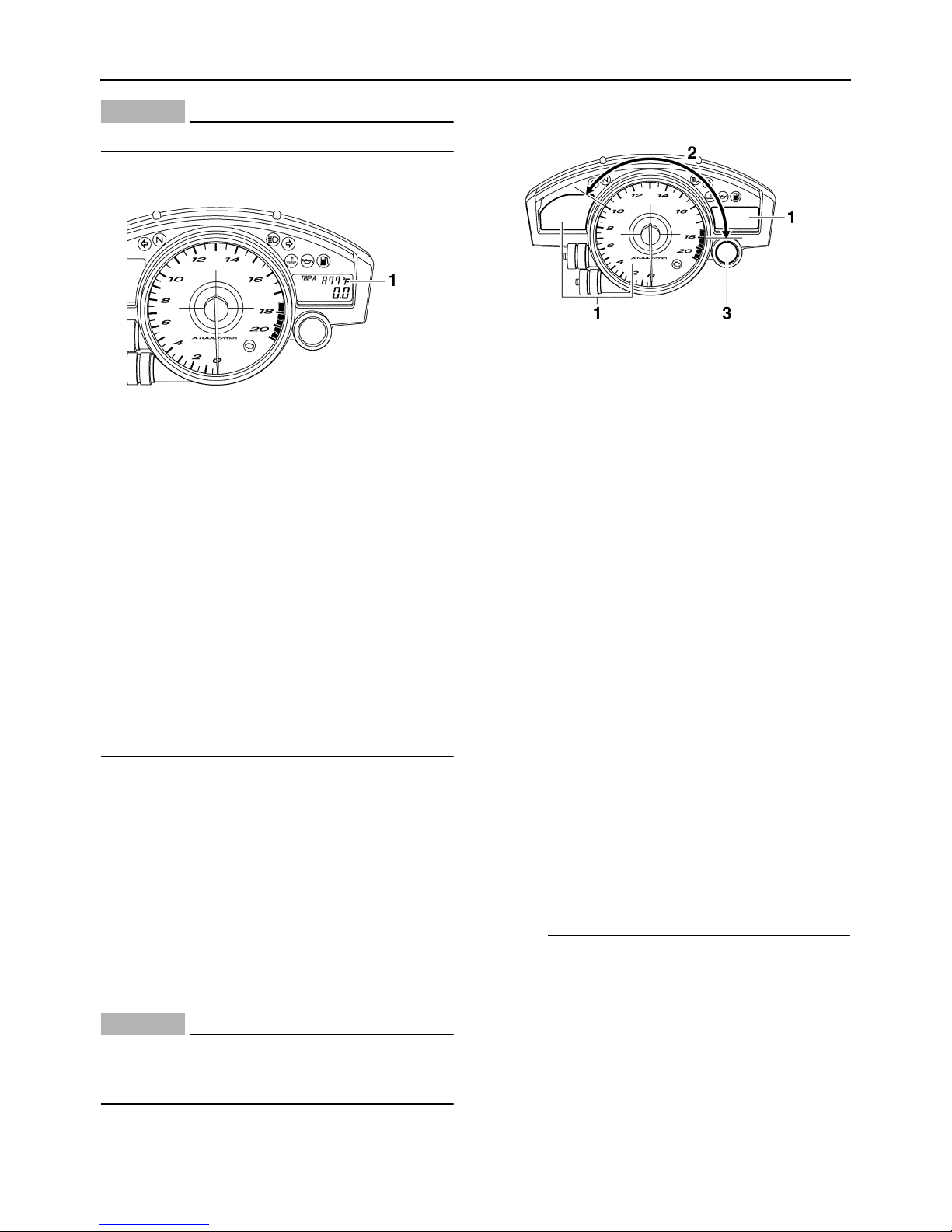
Odometer, tripmeter, and stopwatch modes
1. Odometer/tripmeters/fuel reserve
tripmeter/stopwatch
Push the “SELECT” button to switch the display
between the odometer mode “ODO”, the tripmeter modes “TRIP A” and “TRIP B” and the stopwatch mode in the following order:
TRIP A → TRIP B → ODO → Stopwatch →
TRIP A
If the fuel level warning light comes on, the
odometer display will automatically change to
the fuel reserve tripmeter mode “F-TRIP” and
start counting the distance traveled from that
point. In that case, push the “SELECT” button to
switch the display between the various tripmeter, odometer, and stopwatch modes in the following order:
F-TRIP → Stopwatch → TRIP A → TRIP B →
ODO → F-TRIP
To reset a tripmeter, select it by pushing the “SE-
LECT” button, and then push the “RESET” button for at least one second. If you do not reset
the fuel reserve tripmeter manually, it will reset
itself automatically and the display will return to
the prior mode after refueling and traveling 5 km
(3 mi).
Stopwatch mode
To change the display to the stopwatch mode,
select it by pushing the “SELECT” button. (The
stopwatch digits will start flashing.) Release the
“SELECT” button, and then push it again for a
few seconds until the stopwatch digits stop
flashing.
Standard measurement:
1. Push the “RESET” button to start the stopwatch.
2. Push the “SELECT” button to stop the stopwatch.
3. Push the “SELECT” button again to reset the
stopwatch.
Split-time measurement:
1. Push the “RESET” button to start the stopwatch.
2. Push the “RESET” button or start switch “”
to measure split-times. (The colon “:” will start
flashing.)
3. Push the “RESET” button or start switch “”
to display the final split-time or push the “SE-
LECT” button to stop the stopwatch and display total elapsed time.
4. Push the “SELECT” button to reset the stopwatch.
NOTE:
To change the display back to the prior mode,
push the “SELECT” button for a few seconds.
Coolant temperature display
1. Coolant temperature display
The coolant temperature display indicates the
temperature of the coolant. Push the “RESET”
button to switch the coolant temperature display
to the air intake temperature display.
NOTE:
When the coolant temperature display is selected, “C” is displayed for one second, and then the
coolant temperature is displayed.
1-8
FEATURES
EC2C01021
CAUTION:
Do not operate the engine if it is overheated.
Air intake temperature display
1. Air intake temperature display
The air intake temperature display indicates the
temperature of the air drawn into the air filter
case. Push the “RESET” button to switch the
coolant temperature display to the air intake
temperature display.
NOTE:
• Even if the air intake temperature is set to be
displayed, the coolant temperature warning
light comes on when the engine overheats.
• When the key is turned to “ON”, the coolant
temperature is automatically displayed, even if
the air intake temperature was displayed prior
to turning the key to “OFF”.
• When the air intake temperature display is selected, “A” is displayed before the temperature.
Self-diagnosis device
This model is equipped with a self-diagnosis device for various electrical circuits.
If any of those circuits are defective, the engine
trouble warning light will come on, and then the
odometer/trip meter/fuel reserve trip meter/stopwatch display will indicate a two-digit error code
(e.g., 11, 12, 13).
If the display indicates an error code, note the
code number, and then check the vehicle. Refer
to “FUEL INJECTION SYSTEM” on page 8-33.
EC2C01022
CAUTION:
If the display indicates an error code, the vehicle should be checked as soon as possible
in order to avoid engine damage.
Display brightness and shift timing indicator
light control mode
1. Display brightness
2. Shift timing indicator light
activation/deactivation
3. Shift timing indicator light
This mode cycles through five control functions,
allowing you to make the following settings in the
order listed below.
• Display brightness:
This function allows you to adjust the brightness of the displays and tachometer to suit the
outside lighting conditions.
• Shift timing indicator light activity:
This function allows you to choose whether or
not the indicator light should be activated and
whether it should flash or stay on when activated.
• Shift timing indicator light activation:
This function allows you to select the engine
speed at which the indicator light will be activated.
• Shift timing indicator light deactivation:
This function allows you to select the engine
speed at which the indicator light will be deactivated.
• Shift timing indicator light brightness:
This function allows you to adjust the brightness of the indicator light to suit your preference.
NOTE:
In this mode, the odometer/trip meter/fuel reserve trip meter/stopwatch display shows the
current setting for each function (except the shift
timing indicator light activity function).
1-9

FEATURES
To adjust the brightness of the multi-function
meter displays and tachometer:
1. Turn the key to “OFF”.
2. Push and hold the “SELECT” button.
3. Turn the key to “ON”, and then release the
“SELECT” button after five seconds.
4. Push the “RESET” button to select the desired brightness level.
5. Push the “SELECT” button to confirm the se-
lected brightness level. The control mode
changes to the shift timing indicator light activity function.
To set the shift timing indicator light activity function:
1. Push the “RESET” button to select one of the
following indicator light activity settings:
• The indicator light will stay on when activated.
(This setting is selected when the indicator
light stays on.)
• The indicator light will flash when activated.
(This setting is selected when the indicator
light flashes four times per second.)
• The indicator light is deactivated; in other
words, it will not come on or flash. (This setting is selected when the indicator light flashes once every two seconds.)
2. Push the “SELECT” button to confirm the se-
lected indicator light activity. The control
mode changes to the shift timing indicator
light activation function.
To set the shift timing indicator light deactivation
function:
NOTE:
• The shift timing indicator light deactivation
function can be set between 10000 r/min and
18000 r/min. From 10000 r/min to 13000 r/min,
the indicator light can be set in increments of
500 r/min. From 13000 r/min to 18000 r/min,
the indicator light can be set in increments of
200 r/min.
• Be sure to set the deactivation function to a
higher engine speed than for the activation
function, otherwise the shift timing indicator
light will remain deactivated.
1. Push the “RESET” button to select the de-
sired engine speed for deactivating the indicator light.
2. Push the “SELECT” button to confirm the se-
lected engine speed. The control mode
changes to the shift timing indicator light
brightness function.
To adjust the shift timing indicator light brightness:
1. Push the “RESET” button to select the de-
sired indicator light brightness level.
2. Push the “SELECT” button to confirm the se-
lected indicator light brightness level. The display will return to the odometer or tripmeter
mode.
To set the shift timing indicator light activation
function:
NOTE:
The shift timing indicator light activation function
can be set between 10000 r/min and 18000
r/min. From 10000 r/min to 13000 r/min, the indicator light can be set in increments of 500 r/min.
From 13000 r/min to 18000 r/min, the indicator
light can be set in increments of 200 r/min.
1. Push the “RESET” button to select the desired engine speed for activating the indicator
light.
2. Push the “SELECT” button to confirm the se-
lected engine speed. The control mode
changes to the shift timing indicator light deactivation function.
1-10
EAS20180
IMPORTANT INFORMATION
EAS20190
PREPARATION FOR REMOVAL AND
DISASSEMBLY
1. Before removal and disassembly, remove all
dirt, mud, dust and foreign material.
2. Use only the proper tools and cleaning equipment.
Refer to “SPECIAL TOOLS” on page 1-14.
3. When disassembling, always keep mated
parts together. This includes gears, cylinders,
pistons and other parts that have been “mat-
ed” through normal wear. Mated parts must
always be reused or replaced as an assembly.
IMPORTANT INFORMATION
EAS20210
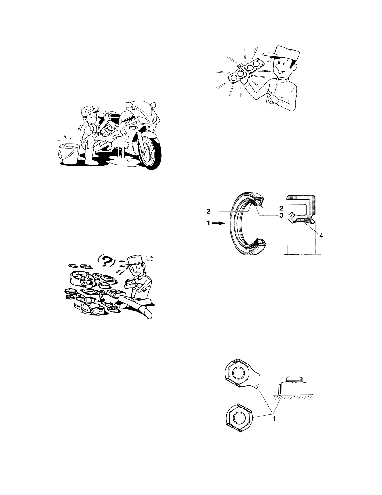
GASKETS, OIL SEALS AND O-RINGS
1. When overhauling the engine, replace all
gaskets, seals and O-rings. All gasket surfaces, oil seal lips and O-rings must be cleaned.
2. During reassembly, properly oil all mating
parts and bearings and lubricate the oil seal
lips with grease.
4. During disassembly, clean all of the parts and
place them in trays in the order of disassembly. This will speed up assembly and allow for
the correct installation of all parts.
5. Keep all parts away from any source of fire.
EAS20200
REPLACEMENT PARTS
Use only genuine Yamaha parts for all replacements. Use oil and grease recommended by
Yamaha for all lubrication jobs. Other brands
may be similar in function and appearance, but
inferior in quality.
1. Oil
2. Lip
3. Spring
4. Grease
EAS20220
LOCK WASHERS/PLATES AND COTTER
PINS
After removal, replace all lock washers/plates
“1” and cotter pins. After the bolt or nut has been
tightened to specification, bend the lock tabs
along a flat of the bolt or nut.
1-11

EAS20230
BEARINGS AND OIL SEALS
Install bearings “1” and oil seals “2” so that the
manufacturer’s marks or numbers are visible.
When installing oil seals, lubricate the oil seal
lips with a light coat of lithium-soap-based
grease. Oil bearings liberally when installing, if
appropriate.
ECA13300
CAUTION:
Do not spin the bearing with compressed air
because this will damage the bearing surfaces.
IMPORTANT INFORMATION
EAS20240
CIRCLIPS
Before reassembly, check all circlips carefully
and replace damaged or distorted circlips. Always replace piston pin clips after one use.
When installing a circlip “1”, make sure the
sharp-edged corner “2” is positioned opposite
the thrust “3” that the circlip receives.
1-12

EAS20250
CHECKING THE CONNECTIONS
Check the leads, couplers, and connectors for
stains, rust, moisture, etc.
1. Disconnect:
• Lead
• Coupler
• Connector
2. Check:
• Lead
• Coupler
• Connector
Moisture → Dry with an air blower.
Rust/stains → Connect and disconnect several times.
CHECKING THE CONNECTIONS
Pocket tester
90890-03112
NOTE:
• If there is no continuity, clean the terminals.
• When checking the wire harness, perform
steps (1) to (3).
• As a quick remedy, use a contact revitalizer
available at most part stores.
Analog pocket tester
YU-03112-C
3. Check:
• All connections
Loose connection → Connect properly.
NOTE:
If the pin “1” on the terminal is flattened, bend it
up.
4. Connect:
• Lead
• Coupler
• Connector
NOTE:
Make sure all connections are tight.
5. Check:
• Continuity
(with the pocket tester)
1-13

SPECIAL TOOLS
EAS20260
SPECIAL TOOLS
The following special tools are necessary for complete and accurate tune-up and assembly. Use only
the appropriate special tools as this will help prevent damage caused by the use of inappropriate tools
or improvised techniques. Special tools, part numbers or both may differ depending on the country.
When placing an order, refer to the list provided below to avoid any mistakes.
NOTE:
• For U.S.A. and Canada, use part number starting with “YM-”, “YU-”, or “ACC-”.
• For others, use part number starting with “90890-”.
Tool name/Tool No. Illustration
Pocket tester
90890-03112
Analog pocket tester
YU-03112-C
Valve lapper
90890-04101
Valve lapping tool
YM-A8998
Vacuum gauge
90890-03094
Carburetor synchronizer
YU-44456
Reference
pages
1-13, 5-35,
8-83, 8-84,
8-85, 8-89,
8-90, 8-91,
8-92, 8-93,
8-94, 8-95,
8-96, 8-97,
8-98, 8-99,
8-100, 8-101
3-5
3-7
Compression gauge
90890-03081
Engine compression tester
YU-33223
Extension
90890-04136
YU-44456
3-10
3-10
1-14
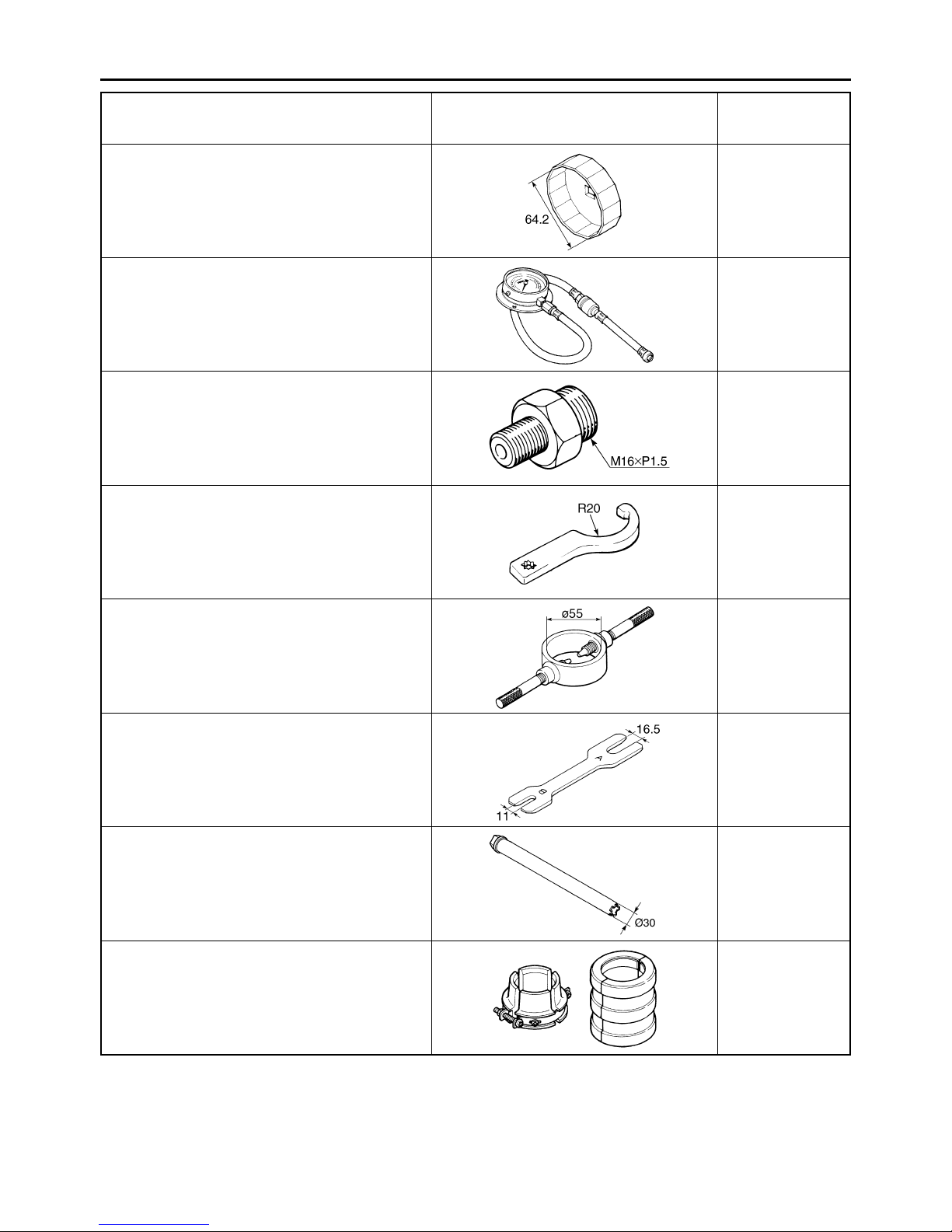
SPECIAL TOOLS
Tool name/Tool No. Illustration
Oil filter wrench
90890-01426
YU-38411
Oil pressure gauge set
90890-03120
Oil pressure adapter H
90890-03139
Steering nut wrench
90890-01403
Spanner wrench
YU-33975
Reference
pages
3-11
3-13
3-13
3-27, 4-58
Fork spring compressor
90890-01441
YM-01441
Rod holder
90890-01434
Damper rod holder double ended
YM-01434
Damper rod holder
90890-01506
YM-01506
Fork seal driver
90890-01442
Adjustable fork seal driver (36–46 mm)
YM-01442
4-47, 4-52
4-47, 4-52
4-48, 4-49
4-50
1-15
SPECIAL TOOLS
Tool name/Tool No. Illustration
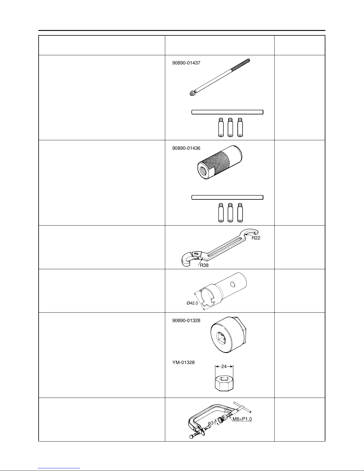
Rod puller
90890-01437
Universal damping rod bleeding tool set
YM-A8703
Rod puller attachment (M10)
90890-01436
Universal damping rod bleeding tool set
YM-A8703
Reference
pages
4-51, 4-52
YM-A8703
4-51, 4-52
YM-A8703
Ring nut wrench
90890-01268
Spanner wrench
YU-01268
Ring nut wrench
90890-01507
YM-01507
Damper rod holder (24 mm)
90890-01328
YM-01328
Valve spring compressor
90890-04019
YM-04019
4-58
4-67, 4-69
4-67, 4-68
5-19, 5-24
1-16
SPECIAL TOOLS
Tool name/Tool No. Illustration
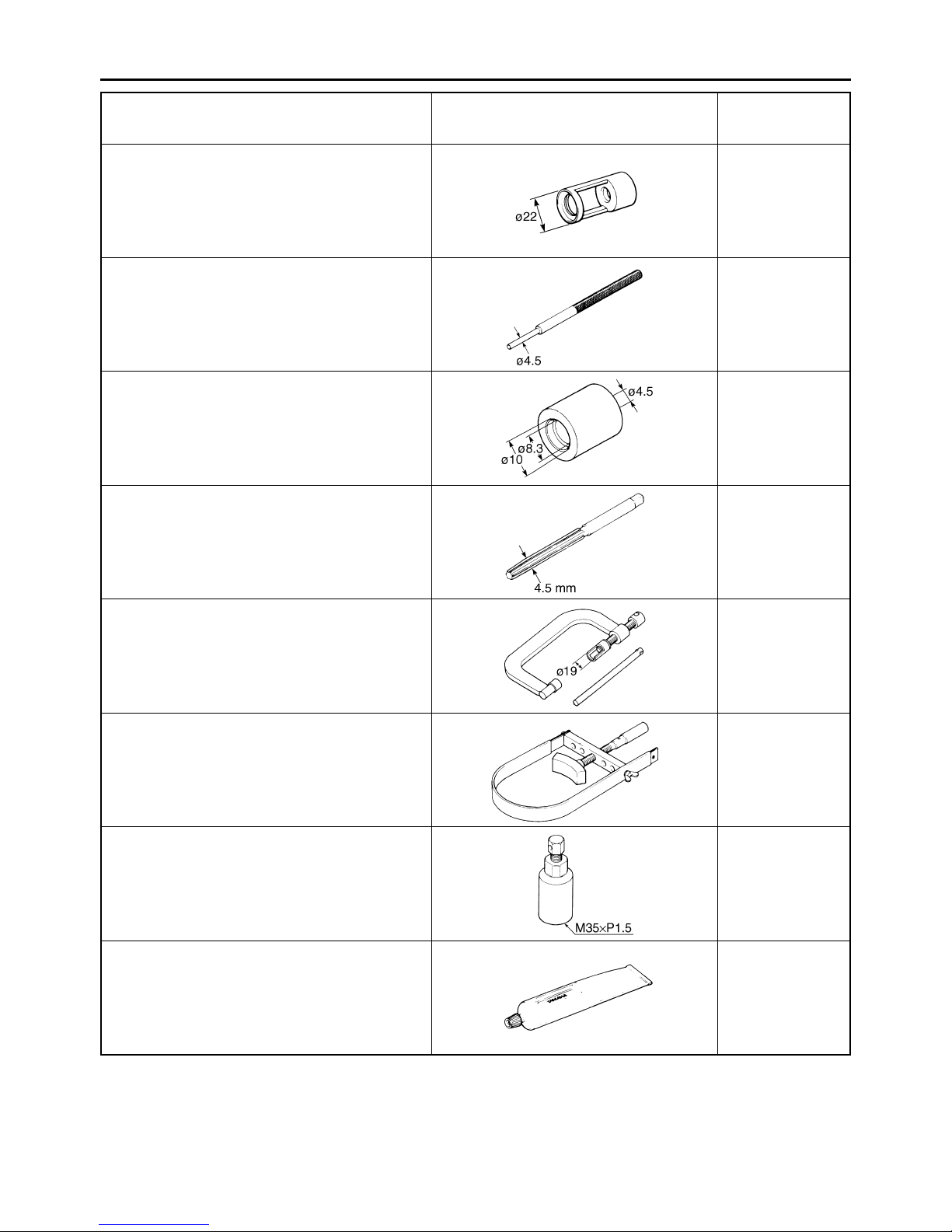
Valve spring compressor attachment
90890-04108
Valve spring compressor adapter 22 mm
YM-04108
Valve guide remover (ø4.5)
90890-04116
Valve guide remover (4.5 mm)
YM-04116
Valve guide installer (ø4.5)
90890-04117
Valve guide installer (4.5 mm)
YM-04117
Valve guide reamer (ø4.5)
90890-04118
Valve guide reamer (4.5 mm)
YM-04118
Reference
pages
5-19, 5-24
5-21
5-21
5-21
Valve spring compressor
90890-04109
Sheave holder
90890-01701
Primary clutch holder
YS-01880-A
Flywheel puller
90890-01404
Flywheel puller
YM-01404
Yamaha bond No. 1215
90890-85505
®
(Three Bond No.1215
)
5-24
5-28, 5-29,
5-31
5-28
5-29, 5-31,
5-57
1-17

SPECIAL TOOLS
Tool name/Tool No. Illustration
Universal clutch holder
90890-04086
YM-91042
Thickness gauge
90890-03180
Feeler gauge set
YU-26900-9
Piston pin puller set
90890-01304
Piston pin puller
YU-01304
0.30
0.35
0.40
0.25
0.20
0.15
0.10
0.05
0.03
Reference
pages
5-41, 5-45
5-41
0.50
5-60
Radiator cap tester
90890-01325
Radiator pressure tester
YU-24460-01
Radiator cap tester adapter
90890-01352
Radiator pressure tester adapter
YU-33984
YU-01304
6-3
YU-24460-01
6-3
YU-33984
1-18
SPECIAL TOOLS
Tool name/Tool No. Illustration
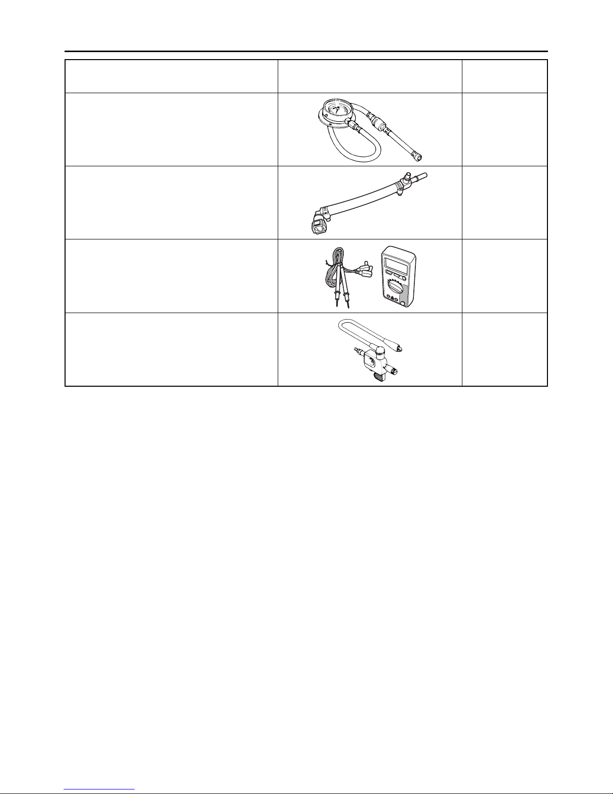
Pressure gauge
90890-03153
Pressure gauge
YU-03153
Fuel pressure adapter
90890-03176
YM-03176
Digital circuit tester
90890-03174
Model 88 Multimeter with tachometer
YU-A1927
Ignition checker
90890-06754
Opama pet-4000 spark checker
YM-34487
Reference
pages
7-12
7-12
7-13
8-92
1-19

SPECIFICATIONS
GENERAL SPECIFICATIONS ........................................................................ 2-1
ENGINE SPECIFICATIONS............................................................................ 2-2
CHASSIS SPECIFICATIONS........................................................................ 2-10
ELECTRICAL SPECIFICATIONS................................................................. 2-13
TIGHTENING TORQUES.............................................................................. 2-16
GENERAL TIGHTENING TORQUE SPECIFICATIONS......................... 2-16
ENGINE TIGHTENING TORQUES......................................................... 2-17
CHASSIS TIGHTENING TORQUES....................................................... 2-21
LUBRICATION POINTS AND LUBRICANT TYPES .................................... 2-25
ENGINE .................................................................................................. 2-25
CHASSIS ................................................................................................ 2-27
2
LUBRICATION SYSTEM CHART AND DIAGRAMS ................................... 2-29
ENGINE OIL LUBRICATION CHART ..................................................... 2-29
LUBRICATION DIAGRAMS.................................................................... 2-31
COOLING SYSTEM DIAGRAMS.................................................................. 2-43
CABLE ROUTING......................................................................................... 2-47

GENERAL SPECIFICATIONS
EAS20280
GENERAL SPECIFICATIONS
Model
Model 2C05/2C08 (USA)
2C06 (California)
Dimensions
Overall length 2040 mm (80.3 in)
Overall width 700 mm (27.6 in)
Overall height 1100 mm (43.3 in)
Seat height 850 mm (33.5 in)
Wheelbase 1380 mm (54.3 in)
Ground clearance 130 mm (5.12 in)
Minimum turning radius 3600 mm (141.7 in)
Weight
With oil and fuel 182.0 kg (401 lb) (USA)
183.0 kg (403 lb) (California)
Maximum load 193 kg (425 lb) (USA)
192 kg (423 lb) (California)
2-1

ENGINE SPECIFICATIONS
EAS20290
ENGINE SPECIFICATIONS
Engine
Engine type Liquid-cooled 4-stroke, DOHC
Displacement 599 cm³ (36.55 cu.in)
Cylinder arrangement Forward-inclined parallel 4-cylinder
Bore × stroke 67.0 × 42.5 mm (2.64 × 1.67 in)
Compression ratio 12.8 :1
Standard compression pressure (at sea level) 1550 kPa/400 r/min (220.5 psi/400 r/min) (15.5
kgf/cm²/400 r/min)
Minimum–maximum 1300–1600 kPa (184.9–227.6 psi) (13.0–16.0
kgf/cm²)
Starting system Electric starter
Fuel
Recommended fuel Premium unleaded gasoline only
Fuel tank capacity 17.5 L (4.62 US gal) (3.85 Imp.gal)
Fuel reserve amount 3.5 L (0.92 US gal) (0.77 Imp.gal)
Engine oil
Lubrication system Wet sump
Type YAMALUBE 4, SAE10W30 or SAE20W40
Recommended engine oil grade API service SF, SG type or higher
Engine oil quantity
Total amount 3.40 L (3.59 US qt) (2.99 Imp.qt)
Without oil filter cartridge replacement 2.40 L (2.54 US qt) (2.11 Imp.qt)
With oil filter cartridge replacement 2.60 L (2.75 US qt) (2.29 Imp.qt)
Oil cooler capacity (including all routes) 0.23 L (2.43 US qt) (2.02 Imp.qt)
Oil pressure (hot) 80.0 kPa/1300 r/min (11.6 psi/1300 r/min) (0.80
kgf/cm²/1300 r/min)
Oil filter
Oil filter type Cartridge (paper)
Oil pump
Oil pump type Trochoid
Inner-rotor-to-outer-rotor-tip clearance Less than 0.12 mm (0.0047 in)
Limit 0.20 mm (0.0079 in)
Outer-rotor-to-oil-pump-housing clearance 0.090–0.150 mm (0.0035–0.0059 in)
Limit 0.220 mm (0.0087 in)
Oil-pump-housing-to-inner-and-outer-rotor
clearance 0.06–0.11 mm (0.0024–0.0043 in)
Limit 0.18 mm (0.0071 in)
Bypass valve opening pressure 78.4–117.6 kPa (11.4–17.1 psi) (0.78–1.18
kgf/cm²)
Relief valve operating pressure 660.0–740.0 kPa (95.7–107.3 psi) (6.60–7.40
kgf/cm²)
Pressure check location MAIN GALLERY
Cooling system
Radiator capacity (including all routes) 2.30 L (2.43 US qt) (2.02 Imp.qt)
2-2
ENGINE SPECIFICATIONS
Coolant reservoir capacity (up to the maximum level
mark) 0.25 L (0.26 US qt) (0.22 Imp.qt)
Radiator cap opening pressure 107.9–137.3 kPa (15.6–19.9 psi) (1.08–1.37
kgf/cm²)
Thermostat
Valve opening temperature 71 °C (159.8 °F)
Valve full open temperature 85 °C (185 °F)
Valve lift (full open) More than 8 mm (0.31 in)
Thermo sensor
Model/manufacturer K003T20191/MITSUBISHI
Resistance at 80 °C 290–354 Ω
Radiator core
Width 374.0 mm (14.72 in)
Height 257.8 mm (10.15 in)
Depth 24.0 mm (0.94 in)
Water pump
Water pump type Single-suction centrifugal pump
Reduction ratio 85/41 × 29/31 (1.939)
Impeller shaft tilt limit 0.15 mm (0.006 in)
Spark plug (s)
Manufacturer/model NGK/CR10EK
Spark plug gap 0.6–0.7 mm (0.024–0.028 in)
Cylinder head
Volume 7.40–8.20 cm³ (0.45–0.50 cu.in)
Warpage limit 0.05 mm (0.0020 in)
Camshaft
Drive system Chain drive (right)
Camshaft cap inside diameter 22.500–22.521 mm (0.8858–0.8867 in)
Camshaft journal diameter 22.459–22.472 mm (0.8842–0.8847 in)
Camshaft-journal-to-camshaft-cap clearance 0.028–0.062 mm (0.0011–0.0024 in)
Limit 0.080 mm (0.0032 in)
Camshaft lobe dimensions
Intake A 33.725–33.875 mm (1.3278–1.3337 in)
Limit 33.675 mm (1.3258 in)
Intake B 25.225–25.325 mm (0.9931–0.9970 in)
Limit 25.175 mm (0.9911 in)
Exhaust A 32.925–33.075 mm (1.2963–1.3022 in)
Limit 32.875 mm (1.2943 in)
2-3
 Loading...