

Page 1
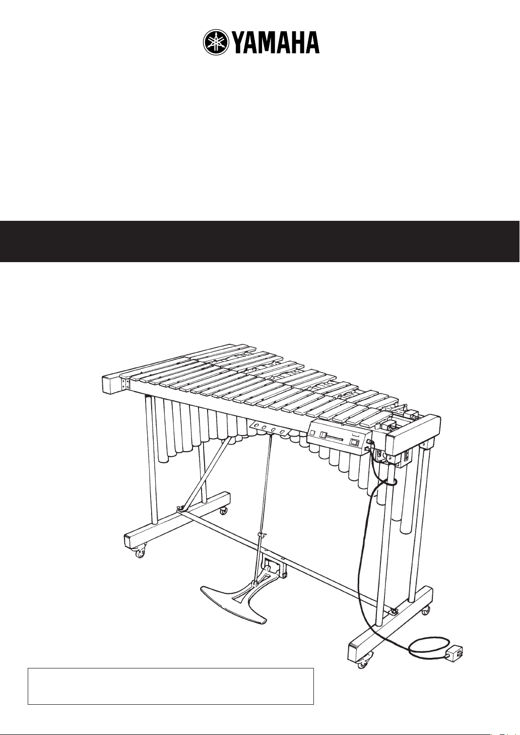
ビブラフォン VIBRAPHONE
YV-600E / YV-500E
立奏鉄琴 METALLOPHONE
YT-300D / YT-280D
取扱説明書 Owner’s Manual
このたびは、ヤマハビブラフォン、立奏鉄琴をお買い上げいただきまして、
誠にありがとうございます。
ご使用の前にこの取扱説明書をお読みいただき、末永くご愛用ください。
『安全へのこころがけ』および『ご使用上の注意』を必ずお読みください。
Make sure to read the PRECAUTIONS AND CARE on page 3.
Page 2
安全へのこころがけ
ビブラフォン/立奏鉄琴はご家庭や学校内で、お子様から専門家まで幅広い方々にご愛用いただいております。
室内での置き場所や日常の取り扱いについて、安全にご使用いただくため、下記の注意を必ず守ってください。
特に小さなお子様には、最初にご家族の方、または指導者から取り扱い方法を指導してください。
火災・感電・人身傷害の危険を防止するには 〜以下の指示を必ず守ってください〜
この「安全へのこころがけ」は製品を安全に正しく
絵表示に
ついて
お使いいただき、お客様や他の人々への危害や財
産への損害を未然に防止するために、いろいろな
絵表示を使って説明しています。絵表示の意味を
よく理解してから、本文をお読みください。
警告
ビブラフォン/立奏鉄琴を使用する前に、以下の指示と
取扱説明書をよく読んでください。
ビブラフォンのコントローラーやドライバーを分解した
り、改造したりしないでください。火災、感電の原因と
なります。
修理/部品の交換などで、取扱説明書に書かれている以
外のことは、絶対にしないでください。必ずサービスセ
ンターに相談してください。
次のような場所での使用や保存はしないでください。火
災、感電の原因となります。
●
温度が極端に高い場所(直射日光の当たる場所、暖房
機器の近くなど)
●
水気の近く(風呂場、濡れた床など)や湿度の高い場所
●
雨水のかかる場所
●
ホコリの多い場所
●
振動の多い場所
ACアダプター使用時、ACアダプターの電源プラグは、
必ずAC100Vの電源コンセントに差し込んでください。
100V以外では火災、感電の原因となります。
ACアダプター使用時、ACアダプターの電源コードを無
理に曲げたり、上に重いものを乗せたりしないでくださ
い。電源コードに傷がつき、火災、感電の原因となりま
す。
楽器のまわりで遊ばないでください。身体をぶつけてけ
がをする恐れがあります。楽器の転倒の原因にもなりま
す。お子様が楽器のまわりであそばないよう注意してく
ださい。
楽器にもたれかかったり、乗ったりしないでください。
楽器が倒れて、大けがをすることがあります。
注意(危険・警告を含む)を促す内容があることを告げ
るものです。
禁止の行為を告げるものです。
例:
行為を強制したり指示する内容を告げるものです。
例:
この表示を無視して誤った取扱いをすると、人が死亡
又は重傷を負う危険の恐れがある内容を示しています。
→ 分解禁止
→ 電源プラグをコンセントから抜く
ドライブユニットに、異物(燃えやすいもの、硬貨、針金
など)や液体(水やジュースなど)を絶対に入れないでくだ
さい。火災、感電の原因となります。
次のような場合は、直ちに電源を切ってACアダプターな
どを取り外し、サービスセンターに修理を依頼してくだ
さい。
●
ACアダプターの電源コードやプラグが破損したとき
●
異物がドライブユニットの内部に入ったり、液体がこ
ぼれたとき
●
ドライブユニットが(雨などで)濡れたとき
●
ドライブユニットに異常や故障が生じたとき
楽器をぐらついた台の上や傾いた所など、不安定な場所
に置かないでください。落ちたり倒れたりして、けがの
原因となります。
キャスターを利用しての移動は、滑らかな平坦面でのみ
行なってください。側枠の上部をささえ、間口の方向へ
ゆっくりと押してください。
キャスターを利用して移動する時には
1.傾いた所や凸凹のある道、じゃり道は避けてくださ
い。楽器が倒れたり暴走したりして危険です。
2.走らないでください。楽器が止まらなくなって、壁に
ぶつかるなどして大けがをすることがあります。
持ち上げて運ぶ際は、必ず2人以上で、側枠を両手で持っ
て運んでください。
※ ビブラフォンの重量
YV-600E:35kg YV-500E:28kg
※ 立奏鉄琴の重量
YT-300D:31kg YT-280D:24kg
2
Page 3
安全へのこころがけ
注意
ビブラフォンは、正常な通気が妨げられることのない所
で使用してください。
ACアダプターの電源コードをコンセントに抜き差しする
ときは、必ず電源プラグを持ってください。
長時間使用しない場合は、電源スイッチを切りACアダプ
ターの電源プラグをコンセントから抜いてください。
必ず付属の専用電源アダプターPA-1207をお使いくだ
さい。他の電源による障害は、保証期間内でも保証でき
ない場合もございますので、十分ご注意ください。
ペダルの下に、手や足を置かないでください。ペダルに
はさまれることがあります。
ご使用上の注意
ビブラフォン/立奏鉄琴をご使用になる前に、以下の注
意事項をよくお読みください。
◆ 取り扱いについて
・ 音板をグロッケン用マレットや、その他の硬いものでた
たかないでください。音板にへこみやキズができたり、
音律が狂う原因ともなります。
・ コントローラーやドライバーを乱暴に取り扱うと、内部回
路などに支障をきたすおそれがありますので、ご注意くだ
さい。
◆ 移動について
移動の際は衝撃を与えないように静かに運んでください。その
際、電源アダプターを抜いてあること、キャスターのストッ
パーがはずしてあることを確認してください。また、平らな床
面以外では、少し持ち上げるようにしてください。
◆ お手入れについて
音板のお手入れには、乾いた柔らかい布やシリコンクロスをご
使用ください。汚れが取れないときは、柔らかい布にエチルア
ルコールを少量含ませてご使用ください。シンナーやベンジ
ン、濡れぞうきんなどは絶対に使わないでください。
◆摩耗部品の交換
スイッチ・ボリューム・接続端子などの部品は、使用とともに
性能が劣化するために摩耗部品といわれています。劣化の進
行度合は、使用環境などによっても大きく異なりますが、劣化
そのものを避けることはできません。
劣化した摩耗部品の交換は、お買上げ店またはヤマハサービス
拠点へご相談ください。
◆ 本書は保管してください
本書をお読みになった後は、大切に保管してください。
この表示を無視して誤った取扱いをすると、人が障害を負ったり、
財産が損害を受ける危険の恐れがある内容を示しています。
回転中のファンには絶対に手を触れないでください。手
をはさまれてけがをすることがあります。
頻繁に移動するような場合は、各部のボルト類がゆるむ
ことがあります。移動後には、ゆるみをチェックし、ゆ
るんでいる場合は締めてください。
マレットは演奏目的以外には使用しないでください。け
がや事故の原因となります。お子様が人の身体をたたく
など、危険な行為をしないように注意してください。
ご使用にならないときは、必ずキャスターのストッパー
をかけておいてください。
PRECAUTIONS AND CARE
• Do not use extra hard mallets for glockenspiel or
other hard materials to strike the vibraphone and metallophone tone bars. These can dent or scratch the
bars and damage their sound quality.
• Avoid outdoor use.
• Do not place heavy objects or sit on the tone bars or
rails. This may damage the frame or loosen the rails.
• When manoeuvring the instrument over short distances, be sure to release the brakes on the caster
wheels and slightly lift the weight off of the wheels
when actually moving.
•When transporting long distances, disassemble and
pack carefully. Disassemble by reversing the assembly procedure.
• Turn the power switch OFF before unplugging the
motor power cord from the AC outlet.
• If the motor should automatically shut off for any
reason, turn the power switch OFF and eliminate the
cause of failure. After a few seconds, the power can
be turned ON, and the motor will run normally.
• Avoid dust. Store the instrument in its case or cover
with a cloth.
• Avoid places with high temperature or humidity and
do not store in direct sunlight.
• Never use wetted cloths or solvents such as thinner or
benzine to clean the instrument. Wipe clean with a
soft, dry cloth.
• Always apply the caster brakes except when moving.
* Dry clean the dust cover.
3
Page 4
特 長
FEATURES
■厳選された音板材
透明な音色、豊かな響きが得られる高力アルミ合金を採
用しています。表面には、まぶしさとサビを防ぐため、
ヘアラインシルバーアルマイト処理を施しました。
■精密な調律
音板の調律は、熟練した技術者の耳と正確なストロボ
チューナーを使用して行なわれます。音色を決定する倍
音調律は、コンサート用楽器と同じく精密に行ないます
ので、ムラのない安定した音色が得られます。
■機能性、耐久性に優れた構造
枠には、充分に乾燥されたブナのムク材を使用しており
ますので、反りや狂いが発生しません。また、木本来の
良さを活かす黒色生地塗装を採用しました。
各長枠間、横枠と長枠の四隅の固定には特殊金具を使用
し、脚部には枠を支えるステーと両脚を結ぶ支柱を配す
るなど、耐久性には万全の配慮がなされています。
扱いやすい便利な位置にマレット差しを設けています。
ストッパー付キャスターを採用しました。
ペダルの高さは、演奏者に合わせて調節可能です。
■ビブラフォンドライブユニット
小型高性能ブラシレスモーターの採用により、ソフトで
デリケートなバイブレーションを伝えます。
回転スピードはコントローラーのスライドボリュームに
よって幅広く変えられます。
コントローラーのSTART/STOPボタンを押すことで、演
奏しながらでもクリック音をたてることなくファンの回
転をオン/オフできます。
■安全性を重視した設計
ビブラフォンのプーリーには、カバーを装着していま
す。
ファンがなんらかの外的な原因で停止するなど、モー
ターに異常な負荷がかかった場合、電流は自動的に停止
しますので、加熱する心配はありません。
■ Top quality materials for tone bars
The clear and soft tone produced by the tone bars is a result
of using the finest quality aluminum alloy possible. To prevent
rust and give a soft, satin-like finish, the tone bars are finished
with a hairline silver alumite finish.
■ Perfect Tuning
Tuning technicians use their highly trained ears as well as
strobe tuners to tune each individual tone bar. To assure
accurate pitch, tuning is performed on the overtones of each
tone bar as well as its fundamental pitch. Tuning is performed
to the same level as concert and pro use instruments to
ensure that pitch is perfect and even over the entire range.
■ Easy to use, lightweight yet sturdy frame.
The frame’s rail and end piece’s are constructed out of solid
beech wood to prevent frame warping. Also, the frame is
finished with a black matte finish which lets the beauty of
the woods grain show through.
For added reinforcement, angle brackets are attached where
the rail and end pieces are connected. Leg stays and a pedal
stay are also incorporated to give added stability to the
frame. A mallet holder is located in an easy to access position.
Casters are equipped with brakes to keep the vibraphone
from moving while playing. The pedal height is also
adjustable.
■ Vibraphone Drive Unit
Using a compact, high quality, brushless motor the drive
unit applies smooth and delicate vibrato to the vibraphone’s
sound. Vibrato speed is regulated by a slider located on the
controller giving the user a wide range of vibrato settings.
The vibrato fans can be stopped using the controller’s stop
switch. The switch is a touch switch which is silent in
operation.
■ Engineered Stability
The Vibraphone pulley is equipped with a cover.
If the fan should stop rotating for whatever reason, the
electric current to the motor will be automatically shut
off preventing the motor from overheating.
4
Page 5
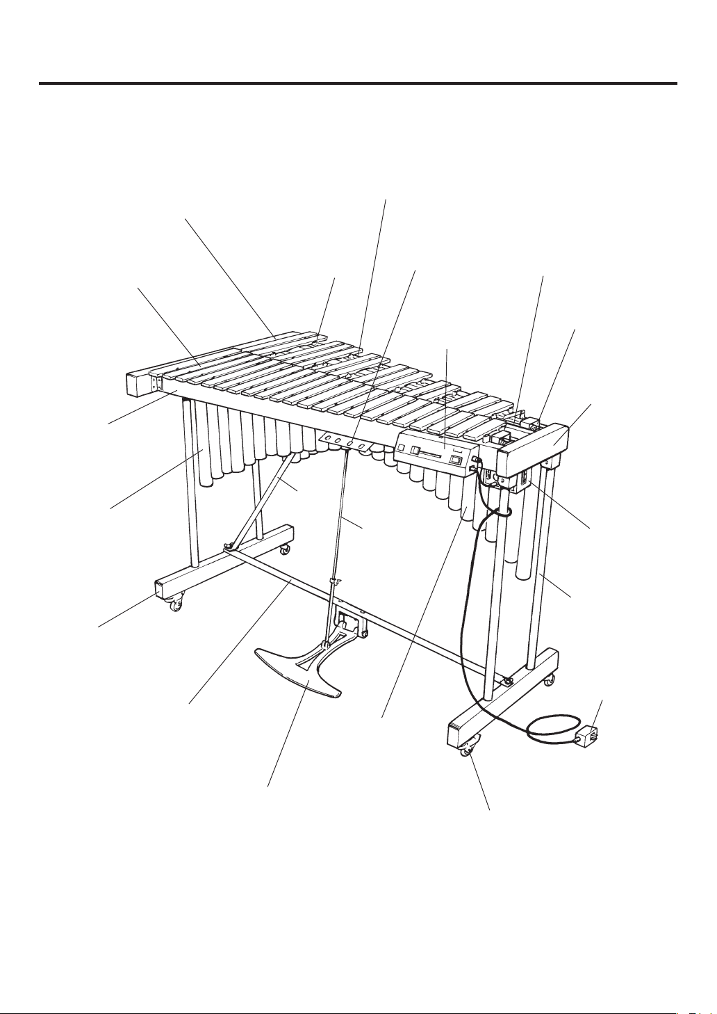
各部の名称 / NOMENCLATURE
音板つづりひも
派生音板
Accidental Tone Bars
Suspension Cord
幹音板
Natural Tone Bars
長枠
Rail
共鳴パイプ
(幹音側)
Resonators
(Natural Tone Side)
脚(大)
Leg (Low End)
吊金
Suspension Post
脚ステー
Leg Stay
マレットさし
Mallet Holder
コントローラー
Controller
ペダルロッド
Pedal Rod
ダンパー
Sustain/Damper
ファンベルト
Fan Belt
横枠
End Piece
ドライバー
Driver
脚(小)
Leg (High End)
電源アダプター
(PA-1207)
AC Adapter
ペダルステー
Pedal Stay
※イラストはYV-600Eです。
※TheillustrationshowsmodelYV-600E
共鳴パイプ(派生音側)
Resonators
(Accidental Tone Side)
ペダル
Sustain/Damper Pedal
キャスター(ストッパー付)
Caster (with brake)
5
Page 6

各部の名称 / NOMENCLATURE
■ビブラフォン・ドライブユニット ■ Vibes Drive Unit
q 電源スイッチ(POWER)
電源のオン/オフを切り替えます。
w スライドボリューム
(MOTORSPEED)
ファンの回転スピードを調節します。
e LEDランプ
電源オンで点灯します。ファン回転中は点滅します。
r スタート/ストップボタン
(START/STOP)
ファンの回転をオン/オフします。
t 電源端子(DC12VIN)
y モーター出力端子(MOTOROUT)
u モーター入力端子(MOTORIN)
i 8p-DINケーブル
o 電源アダプター(PA-1207)
●コントローラー(奏者面)
● Controller (Player Side)
q POWER Switch
Turns the power on and off.
w MOTOR SPEED Slider
Controls the fan rotation speed.
e LED Indicator
Lights when the power is turned on and flashes while
the fan is rotating.
r START/STOP Button
Starts and stops fan rotation.
t DC 12V IN Jack
y MOTOR OUT Terminal
u MOTOR IN Terminal
i 8P DIN Cable
o AC Adapter
●コントローラー(右側面)
● Controller (Right Side)
●ドライバー(奏者面)
● Driver(Player Side)
6
Page 7

部品の確認
/ CONFIRMATION OF PACKING CONTENTS
YV-600E/500E,YT-300D/280Dの梱包箱の中
には、以下の部品が入っています。
組み立ての前に、すべての部品がそろってい
ることを確認してください。
※ 部品が不足している場合は、お買い求めになったお店へ
ご連絡ください。
q 本体 音板/枠/脚/ステー/ダンパー/
ドライバー(YV-600E/500Eのみ)
q Main Unit Tone Bars / Frame / Legs / Sustain
Damper / Driver (YV-600E/500E only)
w ペダルステー
w Pedal Stay
The shipping carton of your YV-2700/1600A
should contain the parts shown below.
Before assembling the instrument, confirm
that all parts are included as listed.
* In the event that a part is missing, please contact the
shop where the instrument was purchased.
r 共鳴パイプ(派生音側)
r Resonators (Accidental Tone Side)
※イラストはYV-600Eです。
※TheillustrationshowsmodelYV-600E
t 電源アダプター
t AC Adapter
e 共鳴パイプ(幹音側)
e Resonators (Natural Tone Side)
y マレット
y Mallet
※YV-600E/500Eのみ
※YV-600E/500Eonly.
i 丸ベルト(ファンベルト):2本
i Round Belt (Fan Belt) : 2 pcs.
o コントローラー
o Controller
u 音板カバー
u Dust Cover
!0 8p-DINケーブル
!0 8P DIN Cable
7
Page 8

組み立て方 / ASSEMBLY
1. 充分なスペースをとり、床にジュータン、または
柔らかい布を敷いた上に本体を裏返します。
2. 左右の脚を開き、蝶ネジを充分にゆるめておきま
す。
1. Be sure that there is sufficient space for assembly.
Turn the instrument upside down onto a carpet or
a floor overlaid with a soft cloth.
2. Fold out both legs and loosen the wing nuts
sufficiently.
8
Page 9

組み立て方 / ASSEMBLY
3. ペダルステーを取り出し、まず高音側から固定し
ます。ステーを差し込んだ後、蝶ネジを締めてく
ださい。低音側は、最初にペダルステーをAの方
向に差し込み、その下に脚ステーをBの方向に差
し込んで固定します。座金は蝶ネジとステーの間
にくるようにし、しっかりとネジを締めてくださ
い。
3. Take out the pedal stay. First, attach the treble
end, and then, tighten into position with the
wing nut. At the bass end, first, attach the
pedal stay as shown by A, then attach the leg
stay below the pedal stay as shown by B in the
diagram below. Place a washer between the
wing bolt and the stays and firmly tighten into
place.
A
B
4. ペダルロッドをダンパーに蝶ネジで固定します。
4. Affix the pedal rod to the damper with the
wing bolt.
9
Page 10

組み立て方 / ASSEMBLY
5. ペダルロッドとペダルを蝶ネジで仮止めしてくだ
さい。
6. 本体を起こします。
5. Fix the position of the pedal rod and the pedal
temporarily with the wing bolt.
6. Set the instrument upright.
7. 共鳴パイプを横枠の溝に高音側から差し込みま
す。
このとき、低音側の溝には、室温22℃以上のとき
は浅いほうへ、22℃以下のときは深いほうへ差し
込みます。
YT-300D/280Dの組立は、この後『11.ペダル踏みしろ
の調整』(→12ページ)をし、各部のネジがしっかりと締
まっていることを確認したら完了です。
7. Insert resonators into the groove of the end
piece at the treble end.
At the bass end of resonators, if the room
temperature is more than 22 °C (72° F), insert
resonators into the shallower grooves; if room
temperature is less than 22°C (72° F), insert
resonators into the deeper grooves.
At this point assembly for models YT-300D/280D is
continued with step #11 “Adjust the pedal stroke”
on page 12. After completing the assembly go back
and make sure all wing nuts are tightened firmly.
10
Page 11

組み立て方 / ASSEMBLY
8. コントローラーを取り付けます。
長枠(1)の高音側上面にコントローラー取付用ピ
ン(2本)があります。
このピンに、コントローラーの2つの穴を合わせ
て片側ずつはめ込みます。
コントローラー取付用ピン
Controller mounting pins
8. Attach the controller.
There are two controller mounting pins on the
high sound side of rail (1). Align the two holes
in the controller mounts with these pins and
hook the controller onto the pins one side at a
time.
高音側
High Sound Side
コントローラー
Controller
9. ドライバーとコントローラーとを接続します。
ドライバーの
MOTOROUT
MOTORIN
端子とコントローラーの
端子とを、付属の8p-DINケーブル*
9. Connect the driver with the controller.
で接続します。
ケーブルのプラグ部分の矢印(
)が各端子のネジ
側に向くようにして、接続します。
コントローラー
Controller
※8p-DINケーブルを紛失された場合は、以下のNo.にてご注文ください。
* In case the 8P DIN cable is misplaced, the following spare part may be ordered:
PartNo. 部品名称/PartName 仕様/Specification
W5172200 8p-DINケーブル/8PDINCable L=220
ネジ
Screw
矢印
Arrow Mark
8p-DINケーブル
8P DIN Cable
Connect the MOTOR IN terminal of the driver
with the MOTOR OUT terminal of the controller
using the supplied 8P DIN cable*.
To connect align the arrow mark ( ) on the plug
with the screw next to the jack.
ドライバー
Driver
ネジ
Screw
矢印
Arrow Mark
11
Page 12

組み立て方 / ASSEMBLY
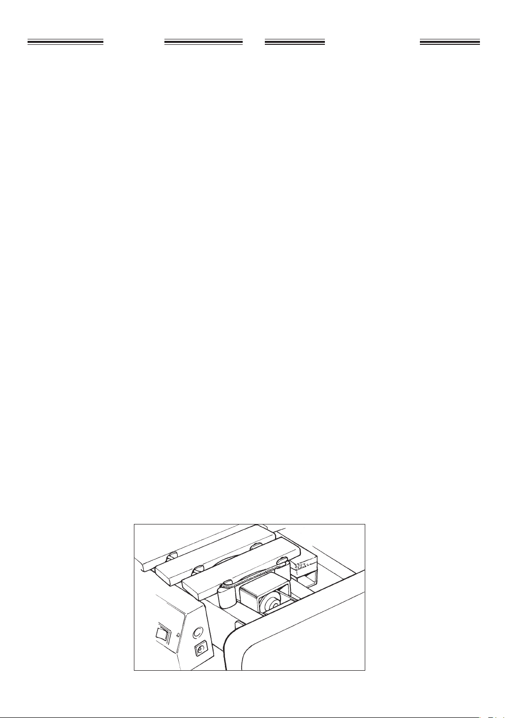
10. 丸ベルト(ファンベルト)
※
を取り付けます。
まずファン側プーリーに丸ベルト(ファンベルト)
をかけ、次にドライバー側プーリーにねじるよう
にしてかけます。
※サービスを実施される方へ
プーリーの間隔が広すぎてベルトがかけられない場合
や、逆に間隔がせまくてベルトが空回りする場合は、ド
ライバー位置調節ネジ(下図)2本をゆるめてベルトの張
り具合を調節してください。調節後は、しっかりとネジ
を締めておいてください。
ファン側
Fan Side Round Belt (Fan Belt)
丸ベルト(ファンベルト)
10. Set the synchro belts (fan belts)*.
First, wrap the synchro belt around the driver
pulley and then carefully slide it over the fan
side pulley.
* Note For Service Personnel
If the belt cannot be mounted because the distance between pulleys is too wide, or the belt slips
due to a too narrow pulley distance, loosen the
two driver positioning screws (see illustration below) to adjust the pulley distance (belt tension).
Tighten the screws securely after adjustment.
ドライバー側
Driver Side
丸ベルト(ファンベルト)
Synchro Belt (Fan Belt)
ドライバー位置調節ネジ
Driver Positioning
Screws
プーリー
Pulley
※ ファンベルトを紛失された場合は、以下のNo.にてご注文ください。
* In case the belt is misplaced or worn, the following spare part may be ordered:
モデル/Model PartNo. 部品名称/PartName 仕様/Specification
YV-600E/500E W5128070 ファンベルト/FanBelt 3マルL236/3φL236
11. ペダル踏みしろを調整します。
センターロッド固定ネジをゆるめ、センターロッ
ドの長さを調整してから再び固定ネジを締めて、
ペダルの踏みしろを調整します。ペダルと床面の
間は1.5〜2cmが適当です。
1.5〜2cm
(9/16"〜13/16")
床面
Floor
プーリー
Pulley
11. Adjust the pedal stroke.
Loosen the center rod fixing bolts to adjust the
protruding length of the center rod to the desired
pedal stroke, and retighten the bolts. The recommended stroke (distance between pedal and floor)
is 9/16" to 13/16" (1.5 to 2 cm).
ペダル
Pedal
12
Page 13

組み立て方 / ASSEMBLY
12. すべて組み上げたら、各部のネジがしっかりと締
まっていることを確認してください。
13. 以上で本体の組立は完了です。
続いて、付属の電源アダプター(PA-1207)をコ
ントローラーの電源端子(DC12VIN)に接続しま
す。
14. 電源の準備
付属の電源アダプター(PA-1207)を用意しま
す。
必ず付属の専用電源アダプター(PA-1207)をご使
用ください。他の電源アダプターの使用は故障の
原因となります。このような場合の故障は、保証
期間内でも保証いたしかねます。
z 電源アダプターのDCプラグをコントローラーの電
源端子(DC12VIN)へ差し込みます。
x 電源アダプターのACプラグを家庭用コンセント
(AC100V)に差し込みます。
12. After assembly, confirm that each bolt and screw
is tightened securely.
13. This completes the assembly of the instru-
ment.
To play, connect the supplied AC adapter to
the DC 12V IN jack of the controller.
14. Power Supply
Prepare the supplied AC adapter.
Make sure to use the supplied AC adapter.
Use of different adapters may cause damage
not covered by the warranty.
z Connect the small plug of the AC adapter to the
DC 12V IN jack on the controller.
x Plug the AC adapter into a power outlet.
コントローラー
Controller
DC12VIN
電源アダプター
AC Adapter
AC
※DCプラグの抜け防止とし
て、コードを本体の脚に1
回巻き付けてから接続する
ことをおすすめします。
* Wrapping the AC adapter cord
once around one of the legs will
prevent accidental disconnection
of the adapter plug.
13
Page 14

仕様
SPECIFICATIONS
■YV-600E
●
音域=C40〜C76(3オクターブ)
●
音板材=高力アルミニウム合金
●
音板幅・厚さ=36mm・13mm
●
寸法(間口×奥行×高さ)=115×67×78cm
●
重量=35kg
●
ドライブユニット=YVM-100
●
定格電圧=D.C.12V
●
最大定格消費電力=6W
●
定格回転数=25〜150RPM
●
電源アダプター=D.C.12V,700mA(YAMAHAPA-1207)
●
付属品=音板カバー、マレット(No.403)
■YV-500E
●
音域=C40〜C76(3オクターブ)
●
音板材=高力アルミニウム合金
●
音板幅・厚さ=32mm・10mm
●
寸法(間口×奥行×高さ)=106×62×78cm
●
重量=28kg
●
ドライブユニット=YVM-100
●
定格電圧=D.C.12V
●
最大定格消費電力=6W
●
定格回転数=25〜150RPM
●
電源アダプター=D.C.12V,700mA(YAMAHAPA-1207)
●
付属品=音板カバー、マレット(No.303)
■YT-300D
●
音域=C40〜C76(3オクターブ)
●
音板材=高力アルミニウム合金
●
音板幅・厚さ=36mm・13mm
●
寸法(間口×奥行×高さ)=115×67×78cm
●
重量=31kg
●
付属品=音板カバー、マレット(No.403)、ダンパー
■YT-280D
●
音域=C40〜C76(3オクターブ)
●
音板材=高力アルミニウム合金
●
音板幅・厚さ=32mm・10mm
●
寸法(間口×奥行×高さ)=106×62×78cm
●
重量=24kg
●
付属品=音板カバー、マレット(No.303)、ダンパー
■YV-600E
•
Range = C40 – C76 (3 Octaves)
•
Bars = Aluminum alloy
•
Bar Size = 36 mm x 13 mm
•
Dimensions (W x D x H) = 115 x 67 x 78 cm
(45-1/4" x 26-3/8" x 3-7/8"')
•
Weight = 35 kg (77 lbs. 2 oz)
•
Drive Unit = YVM-100 Pause controller (25 —250 rpm)
•
Power Supply = YAMAHA AC Adapter PA-1207
D.C. 12V, 700mA
•
Power Consumption = 6W
*
Mallets & Dust Cover included.
■YV-500E
•
Range = C40 – C76 (3 Octaves)
•
Bars = Aluminum alloy
•
Bar Size = 32 mm x 10 mm
•
Dimensions (W x D x H) = 106 x 62 x 78 cm
(41-3/4" x 24-3/8" x 3-7/8"')
•
Weight = 28 kg (61 lbs. 11 oz)
•
Drive Unit = YVM-100 Pause controller (25 —250 rpm)
•
Power Supply = YAMAHA AC Adapter PA-1207
D.C. 12V, 700mA
•
Power Consumption = 6W
*
Mallets & Dust Cover included.
■YT-300D
•
Range = C40 – C76 (3 Octaves)
•
Bars = Aluminum alloy
•
Bar Size = 36 mm x 13 mm
•
Dimensions (W x D x H) = 115 x 67 x 78 cm
(45-1/4" x 26-3/8" x 3-7/8"')
•
Weight = 31 kg (68 lbs. 5 oz)
*
Mallets, Dust Cover & Sustain/Damper included .
■YT-280D
•
Range = C40 – C76 (3 Octaves)
•
Bars = Aluminum alloy
•
Bar Size = 32 mm x 10 mm
•
Dimensions (W x D x H) = 106 x 62 x 78 cm
•
Weight = 24 kg (52 lbs. 14 oz)
*
Mallets, Dust Cover & Sustain/Damper included .
(41-3/4" x 24-3/8" x 3-7/8"')
●音域表/SCALERANGE
YV-600E/YV-500E
YT-300D/YT-280D
27 28 30 32 33 35 37 39 40 42 44 45 47 49 51 52 54 56 57 59 61 63 64 66 68 69 71 73 75 76 78 80 81 83 85 87 88
Middle C
14
※仕様および外観は、予告なく変更することがあります。あらかじめご了承ください。
* Specifications subject to change without notice.
 Loading...