

Yamaha YRS-2100, YRS-1100 Owner's Manua
Surround sound TV stand
Meuble TV surround
OWNER’S MANUAL
MODE D’EMPLOI
BEDIENUNGSANLEITUNG
BRUKSANVISNING
MANUALE DI ISTRUZIONI
MANUAL DE INSTRUCCIONES
GEBRUIKSAANWIJZING

CAUTION: READ THIS BEFORE OPERATING YOUR UNIT.
1 To assure the finest performance, please read this manual
carefully. Keep it in a safe place for future reference.
2 Install this unit in a well ventilated, cool, dry, clean place –
away from direct sunlight, heat sources, vibration, dust,
moisture, and/or cold. For proper ventilation, allow the
following minimum clearances.
Rear: 5 cm (2 in)
Sides: 5 cm (2 in)
3 Locate this unit away from other electrical appliances,
motors, or transformers to avoid humming sounds.
4 Do not expose this unit to sudden temperature changes from
cold to hot, and do not locate this unit in an environment with
high humidity (i.e. a room with a humidifier) to prevent
condensation inside this unit, which may cause an electrical
shock, fire, damage to this unit, and/or personal injury.
5 Avoid installing this unit where foreign object may fall onto
this unit and/or this unit may be exposed to liquid dripping or
splashing. On the top of this unit, do not place:
– Other components, as they may cause damage and/or
discoloration on the surface of this unit.
– Burning objects (i.e. candles), as they may cause fire,
damage to this unit, and/or personal injury.
– Containers with liquid in them, as they may fall and
liquid may cause electrical shock to the user and/or
damage to this unit.
6 Do not cover this unit with a newspaper, tablecloth, curtain,
etc. in order not to obstruct heat radiation. If the temperature
inside this unit rises, it may cause fire, damage to this unit,
and/or personal injury.
7 Do not plug in this unit to a wall outlet until all connections
are complete.
8 Do not operate this unit upside-down. It may overheat,
possibly causing damage.
9 Do not use force on switches, knobs and/or cords.
10 When disconnecting the power cable from the wall outlet,
grasp the plug; do not pull the cable.
11 Do not clean this unit with chemical solvents; this might
damage the finish. Use a clean, dry cloth.
12 Only voltage specified on this unit must be used. Using this
unit with a higher voltage than specified is dangerous and
may cause fire, damage to this unit, and/or personal injury.
Yamaha will not be held responsible for any damage resulting
from use of this unit with a voltage other than specified.
13 To prevent damage by lightning, keep the power cable
disconnected from a wall outlet or this unit during a lightning
storm.
14 Do not attempt to modify or fix this unit. Contact qualified
Yamaha service personnel when any service is needed. The
cabinet should never be opened for any reasons.
15 When not planning to use this unit for long periods of time
(i.e. vacation), disconnect the AC power plug from the wall
outlet.
16 Be sure to read the “TROUBLESHOOTING” section on
common operating errors before concluding that this unit is
faulty.
17 Before moving this unit, press p to set this unit to the
standby mode, and disconnect the AC power plug from the
wall outlet.
18 Install this unit near the AC outlet and where the AC power
plug can be reached easily.
19 The batteries shall not be exposed to excessive heat such as
sunshine, fire or the like. When you dispose of batteries,
follow your regional regulations.
20 Excessive sound pressure from earphones and headphones
can cause hearing loss.
This unit is not disconnected from the AC power source as long as
it is connected to the wall outlet, even if this unit itself is turned off
by p. This state is called the standby mode. In this state, this unit
is designed to consume a very small quantity of power.
WAR NING
TO REDUCE THE RISK OF FIRE OR ELECTRIC SHOCK, DO
NOT EXPOSE THIS UNIT TO RAIN OR MOISTURE.
FOR U.K. CUSTOMERS
If the socket outlets in the home are not suitable for the plug
supplied with this appliance, it should be cut off and an appropriate
3 pin plug fitted. For details, refer to the instructions described
below. Note that the plug severed from the mains lead must be
destroyed, as a plug with bared flexible cord is hazardous if
engaged in a live socket outlet.
IMPORTANT
THE WIRES IN MAINS LEAD ARE COLOURED IN
ACCORDANCE WITH THE FOLLOWING CODE:
Blue: NEUTRAL
Brown: LIVE
As the colours of the wires in the mains lead of this apparatus may
not correspond with the coloured markings identifying the
terminals in your plug, proceed as follows:
The wire which is coloured BLUE must be connected to the
terminal which is marked with the letter N or coloured BLACK.
The wire which is coloured BROWN must be connected to the
terminal which is marked with the letter L or coloured RED. Make
sure that neither core is connected to the earth terminal of the three
pin plug.
CAUTION
Danger of explosion if battery is incorrectly replaced. Replace
only with the same or equivalent type.
CAUTION
Use of controls or adjustments or performance of procedures other
than those specified herein may result in hazardous radiation
exposure.
Notes
• This unit’s speakers use magnets. Do not place items that are
sensitive to magnetism, such as CRT-type TVs, clocks, credit
cards, floppy disks, etc., on top of the rack.
• When the unit is positioned close to a CRT-type TV, picture or
sound distortion may occur. In this case, move the TV away from
the unit.
i En

■ Notes on remote controls and batteries
• Do not spill water or other liquids on the remote control.
• Do not drop the remote control.
• Do not leave or store the remote control in the following places:
– places of high humidity, such as near a bath
– places of high temperatures, such as near a heater or a
stove
– places of extremely low temperatures
– dusty places
• Do not expose the remote control sensor of this unit to direct
sunlight or lighting such as inverted fluorescent lamps.
• If the batteries grow old, the effective operation range of the remote
control decreases considerably. If this happens, replace the batteries
with two new ones as soon as possible.
• Change all of the batteries if you notice the following conditions:
the operation range of the remote control decreases or the
transmission indicator does not light up or becomes dim.
• Do not use old batteries together with new ones.
• Do not use different types of batteries (such as alkaline and
manganese batteries) together. Read the packaging carefully as
these different types of batteries may have the same shape and color.
• Exhausted batteries may leak. If the batteries have leaked, dispose
of them immediately. Avoid touching the leaked material or letting it
come into contact with clothing, etc. Clean the battery compartment
thoroughly before installing new batteries.
• Do not throw away batteries with general house waste. Dispose of
them correctly in accordance with your local regulations.
1 En
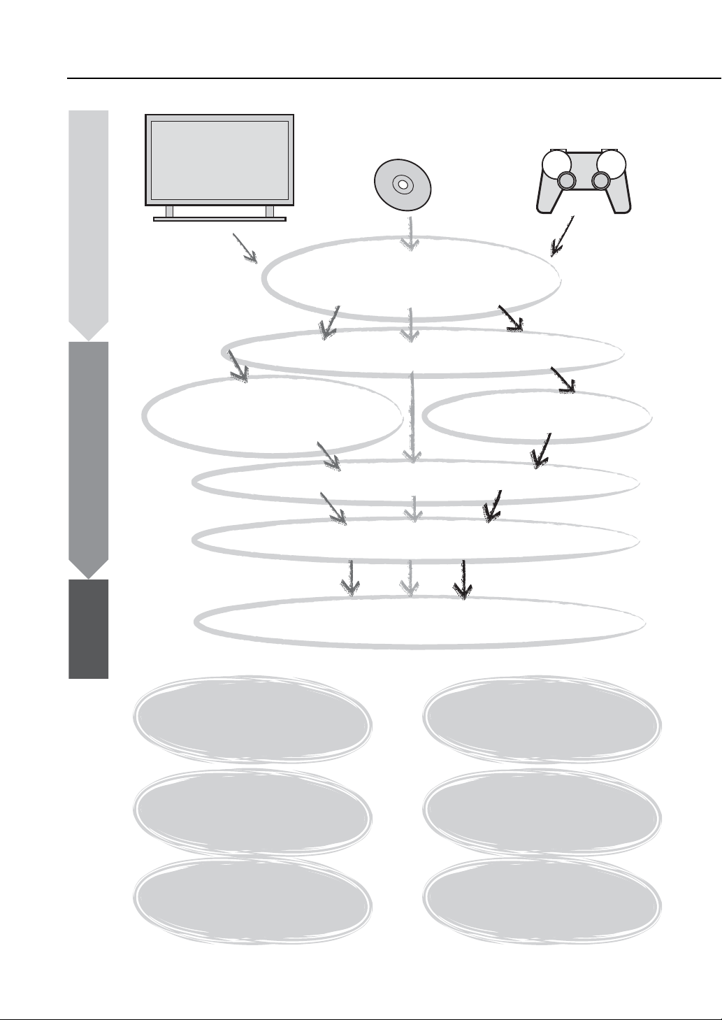
What you can do with this unit
PREPARATION
To enjoy TV
CONNECTION/
INITIAL SETTINGS
To enjoy Blu-ray
Checking supplied accessories (p. 4)
Preparing the remote control (p. 7)
Connecting your TV and Blu-ray disc player (p. 8)
When enjoying STB program
such as on satellite/CATV tuner
(p. 9)
Setting the best possible sound automatically (p. 11)
movies
To enjoy games
Installation (p. 5)
Connecting a game
console (p. 9)
PLAYBACK
Operating the unit by TV’s remote control (p. 18)
Playing back a TV, Blu-ray disc player, and game console (p. 20)
HDMI link (HDMI control)
function
p. 18
IntelliBeam function
p. 11
UniVolume
p. 21
Cinema DSP function
p. 22
Headphone surround function
p. 26
Playing back iPod/iPhone
p. 29
2 En

Contents
PREPARATION
SETTINGS
PREPARATION
Getting started .......................................................4
Supplied accessories .................................................... 4
CONNECTION/INITIAL SETTINGS
Installation..............................................................5
Remote control preparation...........................................7
Connections........................................................... 8
TV and Blu-ray disc player connection.......................... 8
Game console or tuner connection ...............................9
Initial settings.......................................................10
Selecting language for menu display .......................... 10
Auto setup for appropriate surround effects
(IntelliBeam)...........................................................11
Operating the unit by TV’s remote control................... 18
PLAYBACK
Playback features ................................................20
Basic operation for playback ....................................... 20
Enjoying sound with your preference.......................... 21
Switching stereo/surround sound ....................................... 21
Playing back digitally compressed formats (MP3, WMA, etc.)
with enriched sound (Compressed Music Enhancer)......... 21
Automatic volume level adjustment (UniVolume)............... 21
Volume balance adjustment............................................... 21
Enjoying realistic surround sound (CINEMA DSP)............. 22
Changing the audio output method for surround playback........23
Surround decoder setting................................................... 25
Using useful features .................................................. 26
Listening with headphones................................................. 26
Sleep timer/auto power down function ............................... 27
Settings for each input source (Option menu) ....................27
Playing back iPod/iPhone ...........................................29
When using Yamaha Universal Dock for iPod (optional
YDS-12, etc.) .................................................................... 29
When using Wireless System for iPod (optional YID-W10).......29
Playing back Bluetooth components........................... 30
Pairing ................................................................................ 30
Connecting ......................................................................... 31
Setup menu...........................................................32
Setting procedure........................................................32
Setup menu list............................................................33
Manual setup...............................................................34
Setting parameters ........................................................... 34
Beam adjustment .............................................................. 35
Image location .................................................................. 36
Tone control ................................................................36
Tone control ...................................................................... 36
Subwoofer settings ........................................................... 36
Audio delay control ........................................................... 36
Dynamic range control ...................................................... 37
Volume level of each channel with test tones ................... 37
Sound out setting ........................................................37
Sound beam output configuration ..................................... 37
Input assignment.........................................................38
Input assignment .............................................................. 38
Input rename..................................................................... 39
HDMI setup ....................................................................... 39
DISPLAY MENU ............................................................... 40
Advanced setup ...................................................41
TROUBLESHOOTING
Troubleshooting...................................................42
ABOUT THIS UNIT
Controls and functions........................................46
Glossary................................................................49
Specifications.......................................................51
Using the supplied demonstration DVD.............53
Index......................................................................54
INITIAL SETTINGS PLAYBACK SETTINGS
TROUBLESHOOTING
ABOUT THIS UNIT English
CONNECTION/
About this manual
• In this manual, operations that can be performed using either the front panel buttons or the remote control are explained using the
remote control.
y indicates a tip for your operation.
•
• Notes contain important information and operating instructions.
• This manual is produced prior to production. Design and specifications are subject to change in part as a result of improvements,
etc. In case of differences between the manual and the product, the product has priority.
• The alphabet mark (such as ) indicates the remote control key(s) indicated on the figure on the left page.
3 En
PREPARATION
Getting started
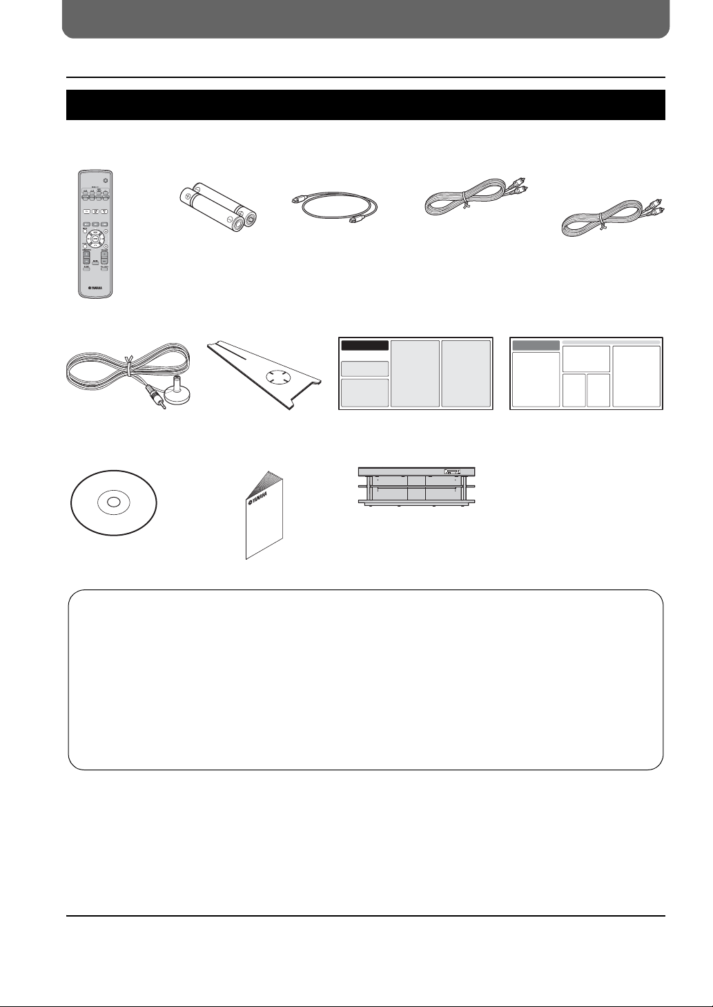
Supplied accessories
Before assembly and connecting, make sure you have received all of the following items.
Remote control Battery (× 2)
(AA, R6, UM-3)
Optical cable
(1.5 m (4.9 ft))
Digital audio pin cable
(1.5 m (4.9 ft))
1)
Video pin cable
(for displaying menu
and iPod video)
(1.5 m (4.9 ft))
IntelliBeam microphone
(× 1) (6 m (19.7 ft))
Demonstration DVD
(☞p. 53)
Assembly is required before using this unit. Make sure all of the following items are included in the package, as they are all
necessary to complete assembly. Refer to the Install Manual for installation.
• Main unit • Rear panels (left and right)
• Shelf • Support posts
• Bottom panel • Center rear panel
• Glass top panel • Brackets
• Pins • Small screws M4 × 10 mm
• Large screws M5 × 30 mm • Washers
• Fasteners
Cardboard microphone
stand (× 1)
Owner’s Manual
(this manual)
Install Manual
Main unit
Quick Reference Guide
1) y
According to the connection, the supplied cables may not be needed.
4 En

CONNECTION/INITIAL SETTINGS
Installation
Place the unit in the appropriate position after assembly. Refer to the supplied Install Manual for assembly. This section describes a
suitable installation location to install this unit. Refer to “Notes on installation” below and place the unit correctly in the safe place.
Notes on installation
• Install your TV in accordance with the manufacturer’s instructions to prevent it from toppling over.
• This unit’s speakers use magnets. Do not place items that are sensitive to magnetism, such as clocks, credit cards, floppy disks, etc., on top of the
rack.
• When the unit is positioned close to a CRT-type TV, picture or sound distortion may occur.
Caution: Handling the tempered glass
The top glass panel is constructed of glass that has been tempered for strength and safety. In addition, a safety film has been applied to the tempered
glass to offer additional protection against injuries that may be caused by shattering glass. However, if you handle the glass inappropriately, the glass
might break and glass fragments might fly, causing injuries. Be sure to follow the precautions listed below:
• Do not allow any strong impacts to the glass (for example, do not allow thrown objects to strike the glass).
• Do not allow sharp objects to contact the glass.
• If the tempered glass has been scratched, it might break unexpectedly. If you see scratches, replace the glass immediately.
• Do not remove the glass caution sticker.
PREPARATION PLAYBACK SETTINGS
INITIAL SETTINGS
CONNECTION/
YRS-1100
Maximum
load
50kg
15kg
30kg
YRS-2100
YRS-1100
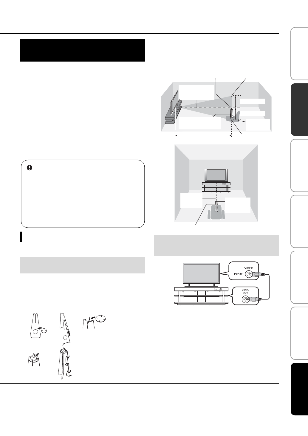
• Install this unit in the center of the left and right walls.
• Listening position (such as sofa, etc.) should be located at the
front of the unit.
• The distance between listening position and the unit should be
more than 1.8 m (6 ft).
YRS-2100
Maximum load
80kg
10kg each
(Left, center
and right)
40kg
Interior slide sheet
An interior slide sheet is attach ed to the
bottom of the unit, allowing you to
move the unit into position easily. To
prevent damage to the floor, clean the
floor of dust and rubbish before moving
the unit.
Before installing this unit
This unit creates surround sound by reflecting projected sound beams off the walls of your listening room. The surround sound effects
produced by this unit may not be sufficient when this unit is installed in the following locations.
• Rooms with walls inadequate for reflecting sound beams
• Rooms with acoustically absorbent walls
• Rooms with measurements outside the following range: W (3 to 7 m (10 to 23 ft)) × H (2 to 3.5 m (7 to 11.5 ft)) × D (3 to 7 m (10 to
23 ft))
• Rooms with less than 1.8 m (6 ft) from the listening position to this unit
• Rooms where objects such as furniture are likely to obstruct the path of sound beams
• Rooms where the listening position is close to the walls
• Rooms where the listening position is not in front of this unit
TROUBLESHOOTING
ABOUT THIS UNIT English
■ My Surround
In the room such as above, you can enjoy rich surround effects by My Surround (☞ p. 24).
5 En
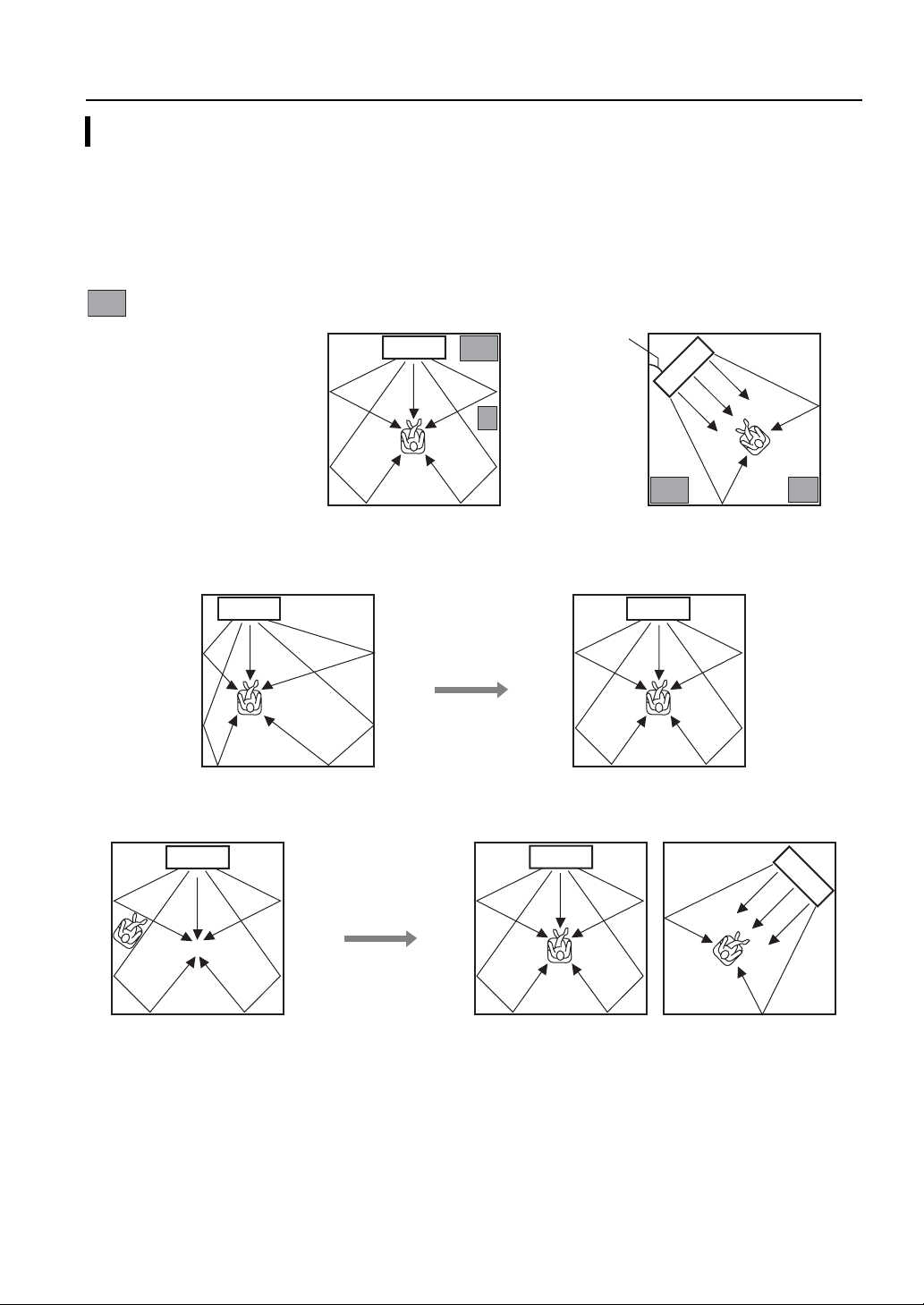
Installation
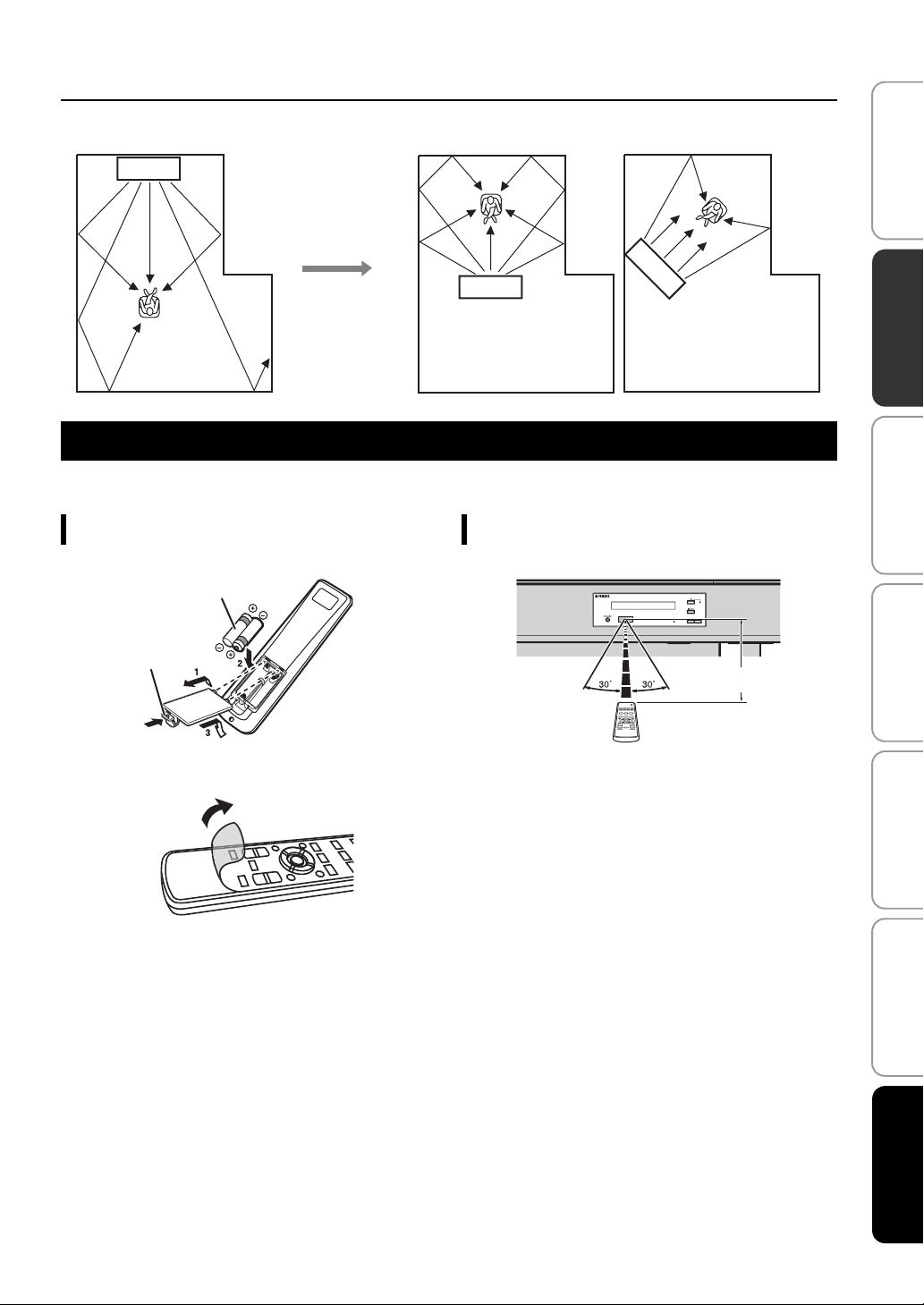
Installing this unit
This unit outputs sound beam as shown in the illustrations below. Install this unit where there are no obstacles such as furniture
obstructing the path of sound beams. Otherwise, the desired surround sound effects may not be achieved.
You may install this unit in parallel with the wall or in the corner.
Parallel installation
Install this unit in the exact center of the wall when it is measured
from the left and right corners
Corner installation
Install this unit in the corner at a 40° to 50° angle from the
adjacent walls.
An object, such as furniture
Parallel installation
(with 5Beam)
■ Installation examples
Parallel installation
Install this unit as close to the exact center of the wall as possible.
Ideal installation condition
Install this unit as close to the exact front of your normal listening position as possible.
The distance between listening position and the unit should be more than 1.8 m (6 ft).
40° to 50°
Corner installation
(with Stereo+3Beam)
6 En
Installation
Installing in a non-square room
Install this unit so that the sound beams can be reflected off the walls.
Remote control preparation
Before installing batteries or using the remote control, make sure that you read precautions on the remote control and batteries in
“CAUTION: READ THIS BEFORE OPERATING YOUR UNIT.”
PREPARATION PLAYBACK SETTINGS
INITIAL SETTINGS
CONNECTION/
Installing the batteries
Battery × 2
(AA, R6, UM-3)
Press U
Remove the transparent sheet before using.
Operation range
Within 6 m (20 ft)
TROUBLESHOOTING
ABOUT THIS UNIT English
7 En
Connections
• Do not connect the power cable until all connections are completed.
• Do not use excessive force when inserting the cable plug. Doing so may damage the cable plug and/or terminal.
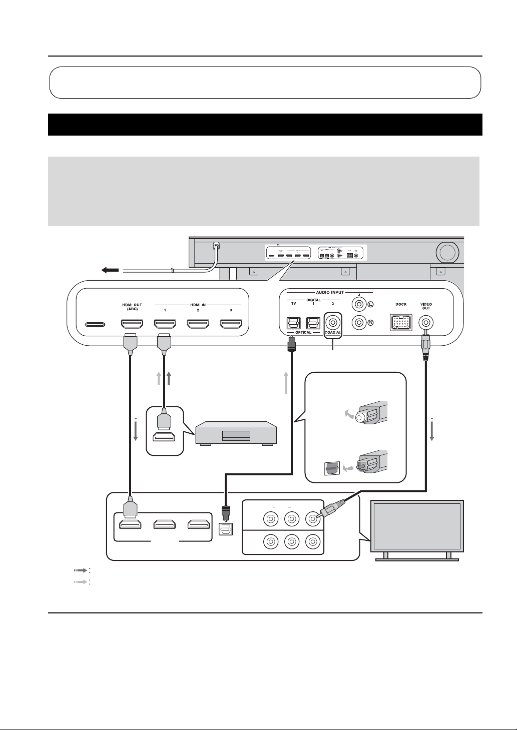
TV and Blu-ray disc player connection
For the cable connection, follow the orders below.
HDMI cable
1
(optional)
Input the digital audio/
video signals of the Bluray disc player to this
unit.
To AC wall outlet
2
1
HDMI cable
2
(optional)
The digital video of the
Blu-ray disc is reflected
on TV.
HDMI
OUTPUT
3
Blu-ray disc player
Optical cable
3
(supplied)
Play back digital sounds
of TV on this unit.
1)
1. Remove the cap
2. Check the direction of
2)
the plug
Video pin cable
4
(supplied)
To display the YRS2100/YRS-1100’s setup
menus on the TV.
4
123
HDMI INPUT
Video signals
Audio signals
1) y
Audio return channel (ARC) supported TV
• Connect HDMI cable to audio return channel supported terminal (the
terminal with “ARC” indicated) on TV. In this case, you do not need
to connect optical cable.
• Activate the HDMI control function of this unit (☞p. 39).
OPTICAL
OUTPUT
8 En
AUDIORL
INPUT1
INPUT2
What is audio return channel (ARC)?
A function transmits digital audio signal output from TV to this unit
through a HDMI cable. By this function, a digital audio pin cable to
connect TV and this unit is not needed.
2) y
Depending on the setting, HDMI for video signal and optical digital
audio, coaxial digital audio or analog audio for audio signal can be
selected. Refer to “Input assignment (☞p. 38)”.
VIDEO
(Example)
TV
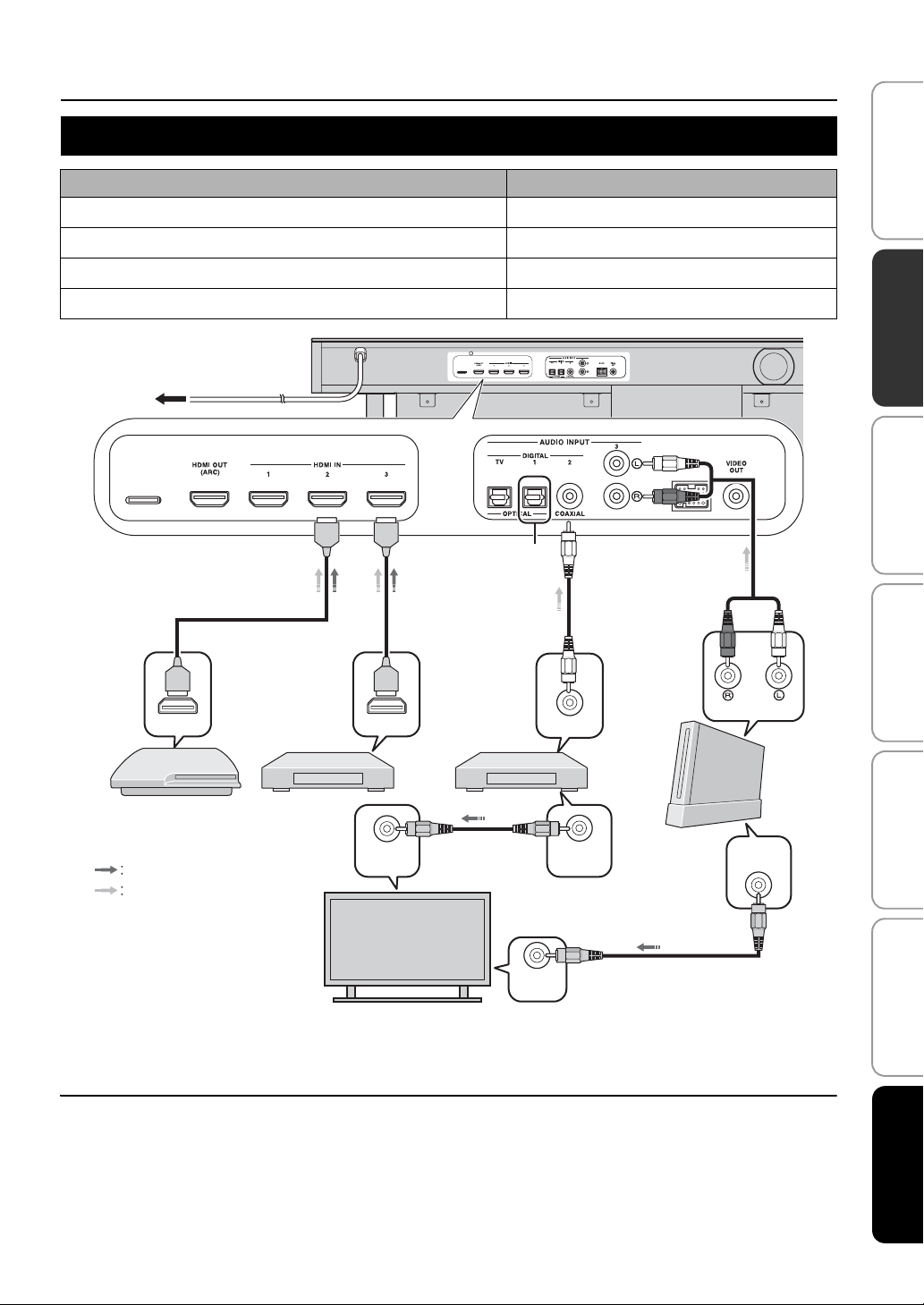
Game console or tuner connection
Additional external device (example) Connecting cable
1 HDMI supported game console
2 Satellite/cable TV (HDMI supported)
3 Satellite/cable TV (HDMI not supported)
4 HDMI not supported game console
To AC wall outlet
Connections
HDMI cable (optional)
HDMI cable (optional)
Digital audio pin cable (supplied)
4)
Analog audio stereo pin cable (optional)
3)
PREPARATION PLAYBACK SETTINGS
INITIAL SETTINGS
CONNECTION/
4)
HDMI
OUTPUT
HDMI
OUTPUT
COAXIAL
OUTPUT
1 2 3 4
(Example)
Video signals
VIDEO
INPUT
Audio signals
TV
3) y 4) y
The additional devices having an optical digital output jack, connect to
the optical digital input jack of this unit with an optical cable.
4)
VIDEO
INPUT
VIDEO
OUTPUT
To connect a game console or tuner to TV, you need extra video pin
cables (optional).
(Example)
(Example)
(Example)
ANALOG
OUTPUT
TROUBLESHOOTING
VIDEO
OUTPUT
ABOUT THIS UNIT English
4)
9 En
Initial settings
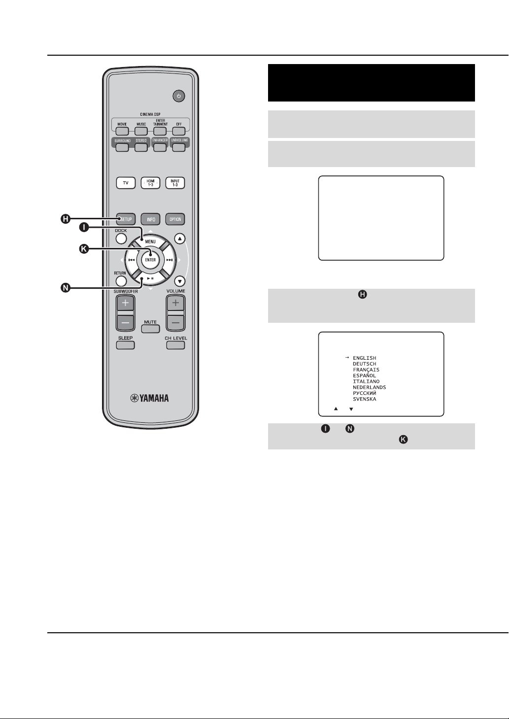
Selecting language for menu display
Turn the unit and your TV on.
1
Switch TV’s input to “VIDEO INPUT 1
2
(example)”.
YRS-
2100
Push [SETUP] to
begin SETUP MENU.
(example)
Check whether the initial screen is displayed.
Press and hold SETUP key until the
3
“LANGUAGE SETUP” menu appears on
your TV.
1)
3)LANGUAGE SETUP
[ ]/[ ]:Sel [ENTER]:Return
Press U / V key to select the desired
4
language and then press ENTER key.
Selectable item: ENGLISH, DEUTSCH, FRANÇAIS,
ESPAÑOL, ITALIANO, NEDERLANDS, РУССКИЙ,
SVENSKA
Initial setting: English
1) y
When the screen is not displayed
Confirm the case followings.
10 En
– The input jack of your TV and the video output jack of the unit are
connected.
– The input of your TV is set to “VIDEO INPUT 1 (example)”.
Auto setup for appropriate surround effects (IntelliBeam)
This unit creates a sound field by reflecting sound beams on the
walls of your listening room and by broadening the cohesion of
all the channels. Just as you would arrange the speaker position of
other audio systems, you need to set the beam angle to enjoy the
best possible sound from this unit.
This unit employs the beam optimization and sound optimization
features with the aid of the supplied IntelliBeam microphone, allowing
you to avoid troublesome listening-based setup and achieving highly
accurate sound adjustments that best match your listening
environment. We call these two features “IntelliBeam” generically.
Beam optimization:
This feature optimizes the beam angle so that the parameter best
matches your listening environment.
Sound optimization:
This feature optimizes the beam delay, volume, and quality so
that the parameters best match your listening environment.
This unit performs these two automatic optimizations with the aid
of the supplied IntelliBeam microphone.
Note
• The AUTO SETUP procedure may not be run successfully if this
unit is installed in one of the rooms described in “Installing this
unit” on page 6. In such cases, run MANUAL SETUP (☞p. 14) to
manually adjust the corresponding parameters.
• Do not connect the IntelliBeam microphone to an extension cable
as doing so may result in an inaccurate sound optimization.
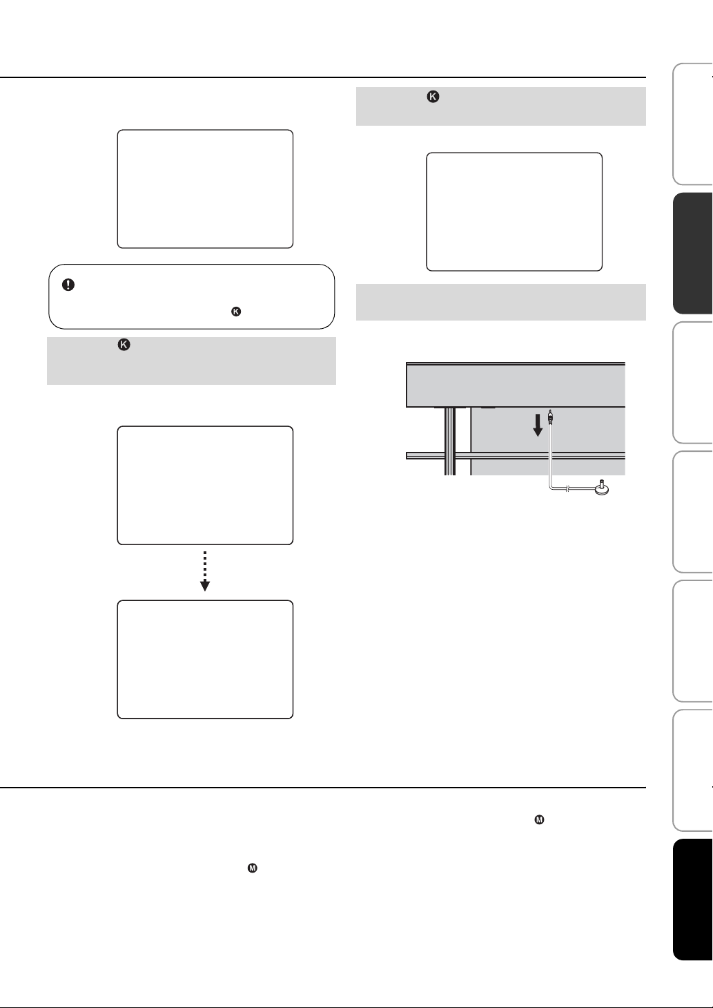
• After you have completed the AUTO SETUP procedure, be sure
to disconnect the IntelliBeam microphone.
• The IntelliBeam microphone is sensitive to heat.
– Keep the IntelliBeam microphone away from direct sunlight.
– Do not place the IntelliBeam microphone on top of this unit.
2)
Initial settings
Make sure that there are no obstacles between the
IntelliBeam microphone and the walls in your listening
room as these objects obstruct the path of sound beams.
However, any objects that are in contact with the walls
will be regarded as a protruding part of the walls.
IntelliBeam microphone Upper limit
Center height of this
unit
Cardboard microphone
stand
1.8 m (6.0 ft)
or more
Center line
Cardboard microphone stand
Within 1 m (3.3 ft)
Within 1 m (3.3 ft)
Lower limit
IntelliBeam
microphone
Listening
position
PREPARATION PLAYBACK SETTINGS
INITIAL SETTINGS
CONNECTION/
Installing the IntelliBeam microphone
Follow the procedure below to connect the IntelliBeam
microphone to this unit and place it in a proper location.
Place the IntelliBeam microphone on a flat
1
level surface at your normal listening position.
Use the supplied cardboard microphone stand or a tripod
to place the IntelliBeam microphone at the same height as
your ears would be when you are seated.
■ Assembling the supplied cardboard
microphone stand
1 2 3
Remove
Place
horizontally
2) y
• “BEAM+SOUND OPTIMIZE” screen appears automatically when
the IntelliBeam microphone is connected. “BEAM OPTIMIZE
ONLY” or “SOUND OPTIMIZE ONLY” can be selected separately
in setup menu (☞p. 14).
Fit in
Run
54
through
Fit in
Check if a supplied video pin cable is
2
connected and headphones are not
connected.
• Data set automatically can be saved in the system memory (☞p. 16).
You can save the several data depending on listening room and you
can change the setting conveniently.
TROUBLESHOOTING
ABOUT THIS UNIT English
11 En
Initial settings
Using AUTO SETUP (IntelliBeam)
Note
• It is normal for loud test tones to be output during the AUTO
SETUP procedure. Make sure that there are no children around
in the listening room while the AUTO SETUP procedure is in
progress.
• Make sure that your listening room is as quiet as possible. For
accurate measurement, turn off air conditioner or other devices
that make noises.
• If there are curtains in your listening room, we recommend
following the procedure below.
1 Open the curtains to improve sound reflection.
2 Run “BEAM OPTIMIZE ONLY”.
3 Close the curtains.
4 Run “SOUND OPTIMIZE ONLY”.
Turn the unit and your TV on.
1
Switch TV’s input to “VIDEO INPUT 1
2
(example)”.
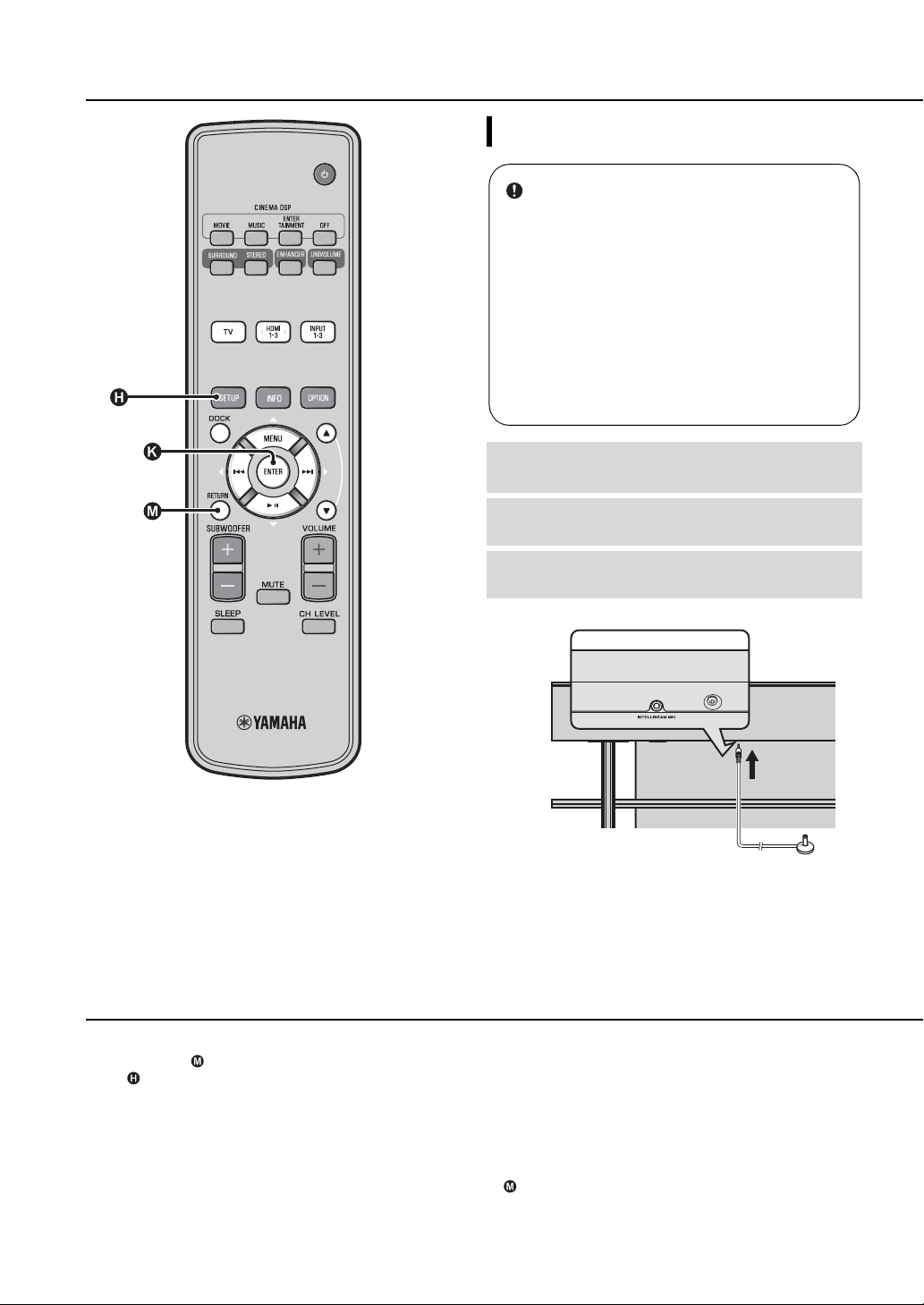
Connect the supplied IntelliBeam
3
microphone to the INTELLIBEAM MIC jack.
1) y 2) y
When pressing RETURN key displays the setup menu
Press SETUP key repeatedly and display the menu screen again, then
select: “AUTO SETUP” “BEAM+SOUND OPTIMIZE”.
When the screen is not displayed
Confirm the case below.
– The input jack of your TV and the video output jack of the unit are
connected.
– The input of your TV is set to “VIDEO INPUT 1 (example)”.
“BEAM+SOUND OPTIMIZE” is selected automatically. When you
perform “BEAM OPTIMIZE ONLY” or “SOUND OPTIMIZE ONLY”
only, refer to “AUTO SETUP via setup menu (☞p. 14)”.
3) y
• Wait outside the room during the AUTO SETUP procedure.
• The AUTO SETUP procedure takes about 3 minutes.
• To cancel the AUTO SETUP procedure after it is started, press
RETURN key.
The jack is on the underside of the main unit.
IntelliBeam microphone
12 En
The screen below is displayed after connecting
IntelliBeam microphone to the unit.
AUTO SETUP
(PREPARATION & CHECK)
Please connect the MIC.
Please place the MIC at least
1.8m/6ft away from SoundProjector. The MIC should be set
at ear level when seated.
Measurement takes about 3min.
After [ENTER] is pressed,
please leave the room.
[ENTER]:Start [RETURN]:Cancel
1) 2)
Press ENTER key to confirm the
5
results.
The measurement result is saved.
5)
AUTO SETUP COMPLETE
Please remove the MIC
from Sound Projector
and the listening position.
Initial settings
PREPARATION PLAYBACK SETTINGS
INITIAL SETTINGS
CONNECTION/
Note
The best setting may not be done if you are in the room. Prepare to
leave the room in 10 seconds after pressing ENTER in step 4.
Press ENTER key to start the AUTO
4
SETUP procedure and then leave the room
within 10 seconds.
The setup screen automatically changes during the AUTO
SETUP procedure.
3)
AUTO SETUP START
Will begin in 10 sec.
Please leave the room.
---------
[RETURN]:Cancel
(After 3 min.)
XXXXXXXXSHOW RESULTXXXXXXXXXX
MEASUREMENT COMPLETE.
BEAM MODE :5Beam/Plus2
SUBWOOFER :Yes
[ENTER]:Save set-up.
[RETURN]:Do
not save
set-up.
Remove the IntelliBeam microphone.
6
Initial screen appears.
Keep the IntelliBeam microphone in a safe place.
The measurement results are stored in the internal
memory of this unit until you run the AUTO SETUP
procedure again or configure the settings manually.
You can save the several measurement result using
memory setting function (☞p. 16).
6)
TROUBLESHOOTING
If AUTO SETUP procedure is complete, this unit rings
the chimes.
4) y 5) y
• If an error occurs, an error buzzer sounds and an error message is
displayed. For details on error messages, see “Error messages for
AUTO SETUP” (☞p. 15).
• If “ENVIRONMENT CHECK:Failure” is displayed, refer to “Error
messages for AUTO SETUP” (☞p. 15), press RETURN key, and
then run the AUTO SETUP procedure again.
• Depending on the environment of your listening room, the beam
angles of front right and left and surround left and right may be set to
the same value even if “BEAM MODE :5 Beam” is displayed as a
result.
4)
If you do not want to reflect the results, press RETURN key.
6) y
When AUTO SETUP is performed from SETUP MENU, menu selection
screen of SETUP MENU appears.
ABOUT THIS UNIT English
13 En
Initial settings
■ AUTO SETUP via setup menu
Place the IntelliBeam microphone and
1
press SETUP key.
Press U / V to select “AUTO SETUP”
2
and then press ENTER key.
Press U / V to select one of the items
3
below and then press ENTER key.
Select Item:
“BEAM+SOUND OPTIMIZE” (Beam optimization
and sound optimization)
It is recommended that you should select this optimization
feature, if you make settings for the first time.
This menu takes about three minutes.
“BEAM OPTIMIZE ONLY”(Beam optimization
only)
Use to optimize the beam angle so that the parameter best
matches your listening environment.
This menu takes about one minute.
“SOUND OPTIMIZE ONLY”(Sound optimization
only)
Use to optimize the beam delay, volume, and quality so
that the parameters best match your listening environment.
You must optimize the beam angle with “BEAM
OPTIMIZE ONLY” before starting “SOUND OPTIMIZE
ONLY”. It is recommended that you should select this
optimization feature in the following cases:
• If you have opened or closed the curtains in your
listening room before using this unit
• If you have manually set the beam angle.
This menu takes about two minutes.
Connect the IntelliBeam microphone to
4
this unit after “AUTO SETUP
(PREPARATION & CHECK)” screen is
displayed.
For the details on installing and connecting IntelliBeam
microphone, refer to “Installing the IntelliBeam
microphone (☞p. 11)”.
14 En
Note
The best setting may not be done if you are in the room. Prepare to
leave the room in 10 seconds after pressing ENTER in step 4.
Perform the step 4, 5 and 6 of “Using
5
AUTO SETUP (IntelliBeam) (☞p. 13)”.
After setup is completed, remove the
6
IntelliBeam microphone.
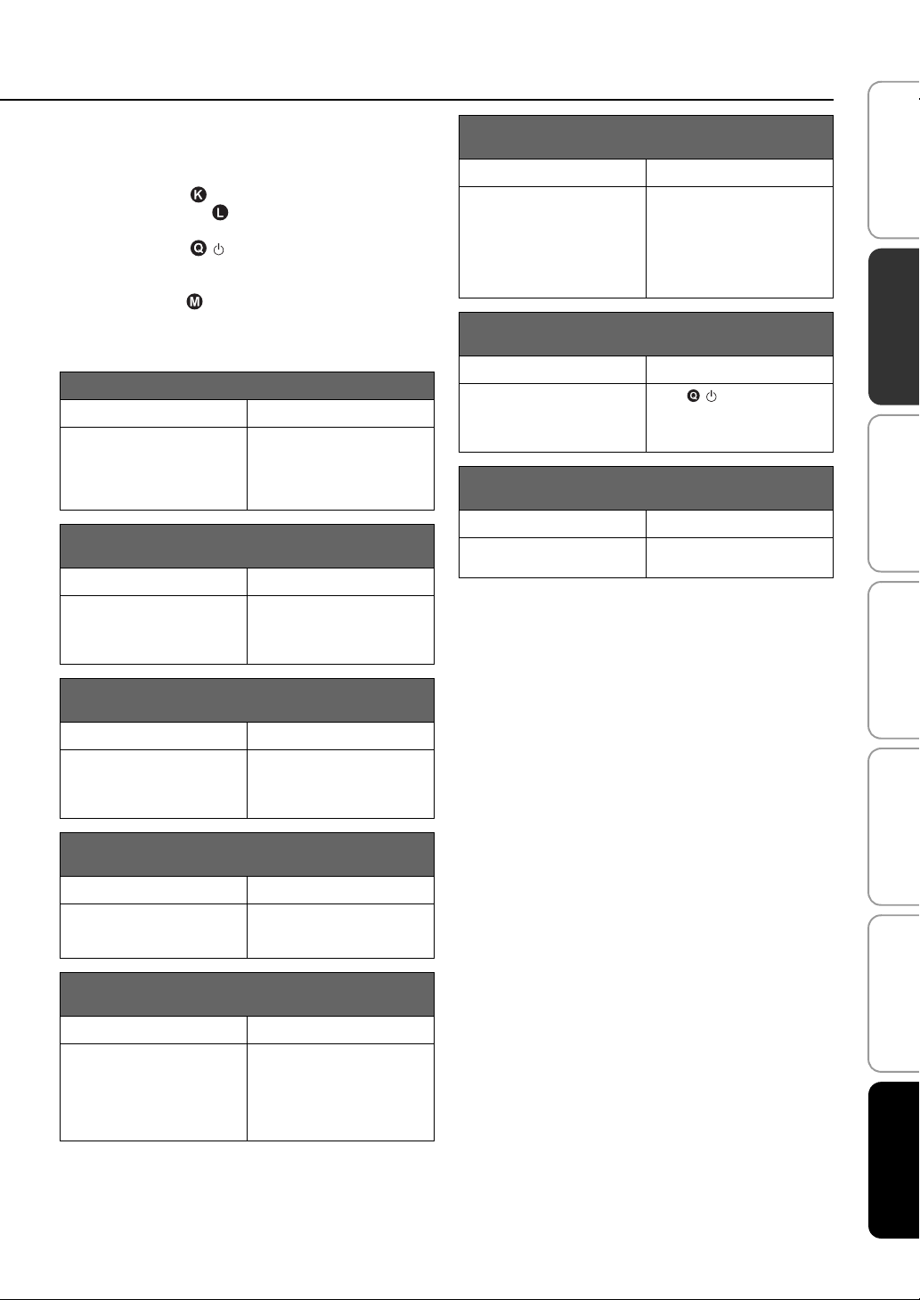
■ Error messages for AUTO SETUP
If an error message is displayed on your TV, check the error
message list to solve the problem and then follow the procedure
below.
[ERROR E-1]: Press ENTER key to run the AUTO SETUP
procedure again. Or press Z key to continue the
measurement.
[ERROR E-7]: Press key to turn this unit to standby
mode, then run AUTO SETUP procedure again after turning this
unit on.
Other errors: Press RETURN key to cancel the operation
and then run the AUTO SETUP procedure again.
If the problem is difficult to be solved, configure the settings
manually in “SETUP MENU” (☞p. 32).
ERROR E-1: Please test in quieter environment.
Cause Remedy
There is too much unwanted
noise in your listening room.
ERROR E-2: No MIC detected. Please check MIC
connection and re-try.
Cause Remedy
The IntelliBeam microphone is
not connected to this unit or
disconnected during the AUTO
SETUP procedure.
Make sure that your listening
room is as quiet as possible. You
may want to choose certain hours
during the day when there is not
much noise coming from outside.
Connect the IntelliBeam
microphone to this unit firmly.
Initial settings
ERROR E-6: Volume level is lower than expected.
Please check MIC position/connection and re-try.
Cause Remedy
The IntelliBeam microphone
cannot collect the sound
produced by this unit because the
sound output level is too low.
Make sure that the IntelliBeam
microphone is firmly connected
to this unit and placed in a proper
location. If the problem persists,
contact the nearest
authorized Yamaha service
center for assistance.
ERROR E-7: Unexpected error happened. Please
turn off and re-try.
Cause Remedy
An internal system error
occurred.
Press key to turn this unit
to standby mode, then run AUTO
SETUP procedure again after
turning this unit on.
ERROR E-8: Headphones are connected. Please
unplug the headphones and re-try.
Cause Remedy
A headphone is connected. Disconnect the headphone and
re-try.
PREPARATION PLAYBACK SETTINGS
INITIAL SETTINGS
CONNECTION/
ERROR E-3: Unexpected control is detected. Please
re-try.
Cause Remedy
Some other operations were
performed on this unit while the
AUTO SETUP procedure was in
progress.
Do not perform any other
operations while the AUTO
SETUP procedure is in progress.
ERROR E-4: Please check MIC position. MIC should
be set in front of the Sound Projector and re-try.
Cause Remedy
The IntelliBeam microphone is
not placed in front of this unit.
Make sure that the IntelliBeam
microphone is installed in front
of this unit.
ERROR E-5: Please check MIC position. MIC should
be set above 1.8m/6.0ft and re-try.
Cause Remedy
The IntelliBeam microphone is
not placed in the right distance
from this unit.
Make sure that the IntelliBeam
microphone is installed more
than 1.8 m (6.0 ft) from the front
of this unit and within 1 m (3.3
ft) from the center height of this
unit.
TROUBLESHOOTING
ABOUT THIS UNIT English
15 En

Initial settings
Saving several measurement results (Memory setting function)
You can save the current beam and sound settings in the system
memory of this unit. It is handy to save certain settings according
to the varying conditions of your listening environment. For
example, if there are curtains in the path of sound beams, the
effectiveness of the sound beams will vary depending on whether
the curtains are open or closed.
If there are curtains in your listening room, we recommend
following the procedure below.
1. While the curtains are open, run “BEAM+SOUND
OPTIMIZE” (☞p. 14) and then save the settings to
“Memory 1”.
2. While the curtains are closed, run “SOUND OPTIMIZE
ONLY” (☞p. 14) and then save the settings to
“Memory 2”.
■ Saving settings
Press SETUP key.
1
Select “MEMORY” and press ENTER
2
key.
Press U / V key to select “SAVE”
3
and then press ENTER key.
Press U / V key to select the desired
4
memory number and then press ENTER
1)
key.
Selectable item: Memory 1, Memory 2, Memory 3
“Memory 1 Save Now ?” is displayed when the memory
number is selected.
Press ENTER key.
5
“Memory 1 Saving…” is displayed and the setting is
saved.
1) y
• If system settings are already stored in the selected memory number,
this unit overwrites the old settings.
• Memory function cannot be set when “MEMORY PROTECT” is set
to “ON” in ADVANCED SETUP (☞p. 41).
16 En
■ Loading settings
Press SETUP key.
1
Select “MEMORY” and press ENTER
2
key.
Initial settings
PREPARATION PLAYBACK SETTINGS
Press U / V key to select “LOAD”
3
and press ENTER key.
Press U / V key to select the
4
memory number to be loaded and then
press ENTER key.
Selectable item: Memory 1, Memory 2, Memory 3
“Memory 1 Load Now ?” is displayed when the memory
number is selected.
Press ENTER key.
5
“Memory 1 Loading…” is displayed and the setting is
loaded.
INITIAL SETTINGS
TROUBLESHOOTING
CONNECTION/
17 En
ABOUT THIS UNIT English

Initial settings
Operating the unit by TV’s remote control
What is the HDMI control function?
You can use the TV remote control to operate this unit if your TV
supports the HDMI control function (ex. REGZA Link) and is
connected to this unit’s HDMI OUT (ARC) jack.
Remote control of TV (Example)
1)
Power on/off
Switches input
This unit automatically
selects the input according to
the input source setting on the
TV. Switching input on TV
menu (ex. selecting Blu-ray
disc player on TV menu) also
changes input of this unit.
1) y
• Even if your TV supports the HDMI control function, some functions
may not be available. For details, refer to the manual supplied with
your TV.
• If you use HDMI to connect this unit to a device such as a Blu-ray
disc player that supports HDMI control, you can control that device
using the HDMI control function.
• We suggest that you use products (TV, Blu-ray disc/DVD player, etc.)
from the same manufacturer.
Controls the volume
Selects a component to
reproduce sounds (this
unit or TV)
18 En
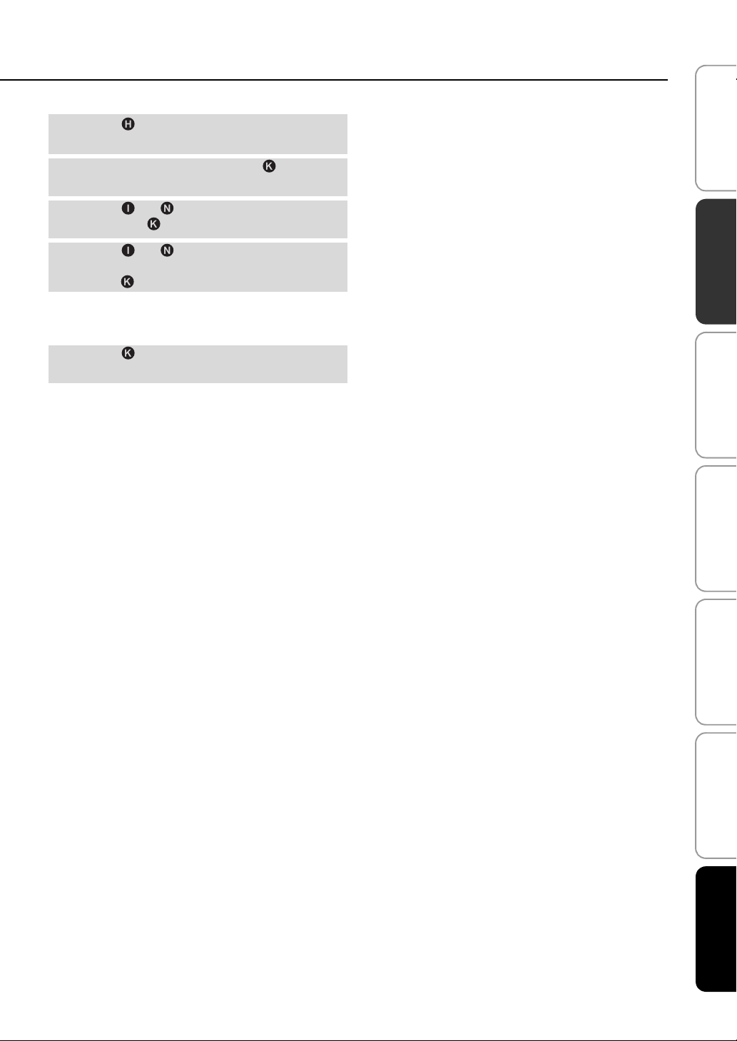
Setting the HDMI control function
Turn on all components connected to this
1
unit with HDMI.
Check all components connected with
2
HDMI and enable the HDMI control
function on each component.
For this unit, set “HDMI CONTROL” to “ON” (☞p. 39).
For external components, refer to the manual supplied
with each component.
Turn off the TV and then turn on it again.
3)
3
Registering HDMI components to TV
Select this unit as the input source of the
1
TV.
Turn on the HDMI control function
2
supported component (example: Blu-ray
disc player) connected to this unit.
Select the input source of this unit to Blu-
3
ray disc player and check whether the
image in the player is correctly displayed
or not.
When connecting Blu-ray disc player with HDMI 1 jack,
press input selector key once to show the following
diagram.
Input source name
Initial settings
PREPARATION PLAYBACK SETTINGS
Check if the HDMI control function works
4
(turn on this unit or adjust the volume level
using the remote control of the TV).
If the HDMI control function is not working
Check the following:
– The TV is connected to the HDMI OUT (ARC) jack of this
2)
4)
unit.
– “HDMI CONTROL” (☞p. 39) is set to “ON” in setup
menu.
– The HDMI control function is enabled on the TV. (Also
check the relative settings such as power interlock function
or speaker priority.)
The HDMI control function is not working even checking the
above,
– Turn off this unit and the TV, and then turn them back on
again.
– Unplug the power cables of the TV and this unit, and plug
them in again.
– After selecting INPUT1, INPUT2, INPUT3 or DOCK,
change the input of TV and the one of this unit to the same
input.
INITIAL SETTINGS
CONNECTION/
Changing the connection method and connected components
When the connected components and jacks are changed, reset this
unit with following procedures.
Turn off the HDMI control function of the
1
TV and player, turn off all connected
devices, and change the connections.
Perform the step 1 to 3 of “Setting the
2
HDMI control function”.
TROUBLESHOOTING
HDMI1
2) y 3) y
• The default setting is “OFF”.
When “HDMI CONTROL” is set to “ON” in setup menu,
– Even you press key, the power does not completely turned
off and the signal outputs from the HDMI IN jack to HDMI OUT
(ARC) jack.
– Before pressing key, select desired input sources connected
to HDMI IN (1 to 3).
– According to the TV, the TV operation such as changing the
channel may change the setting of surround modes of this unit.
The example of TV settings
• From a setup menu on your TV, select “Link setting” “HDMI
control setting” (example), then set a setting such as “HDMI control
function” to “ON” (example).
• Setting such as “Speaker priority” should be set to “AV amplifier”.
4) y
For some HDMI components, you only need to set the HDMI control
function. Registering HDMI components to TV is not required in this
case.
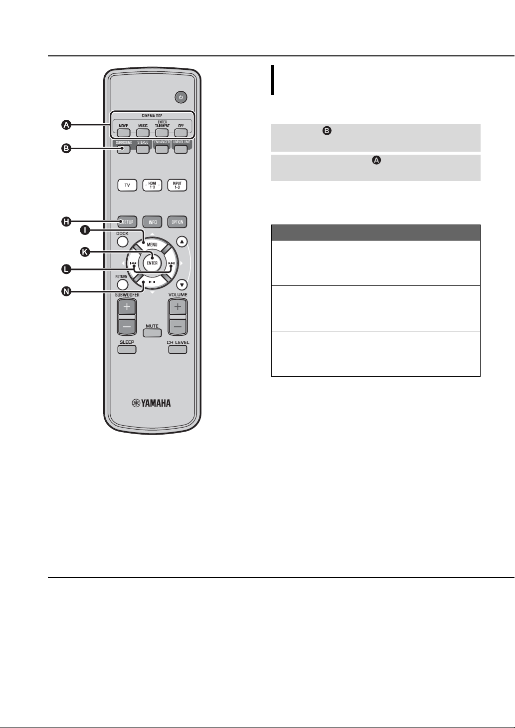
ABOUT THIS UNIT English
19 En
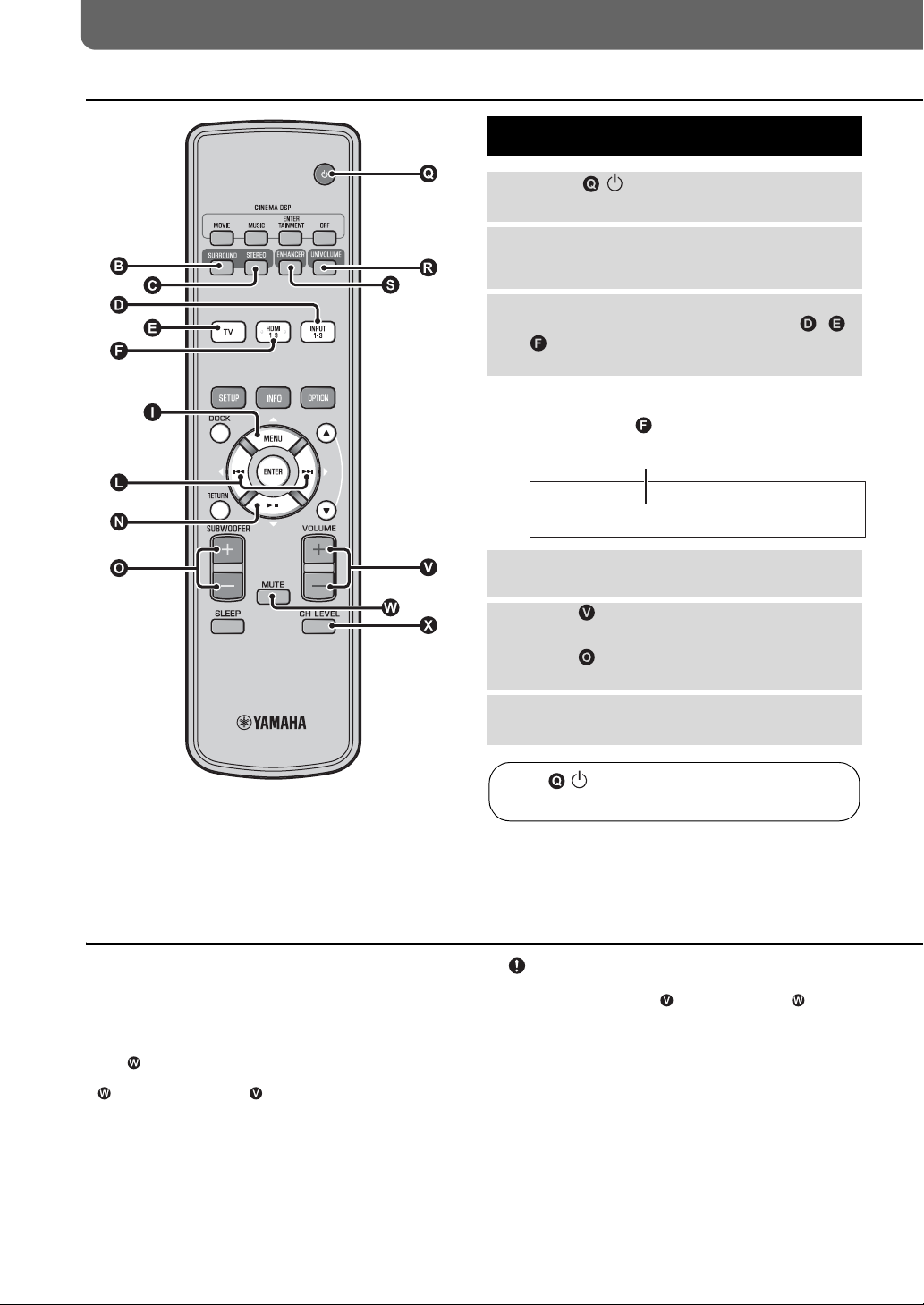
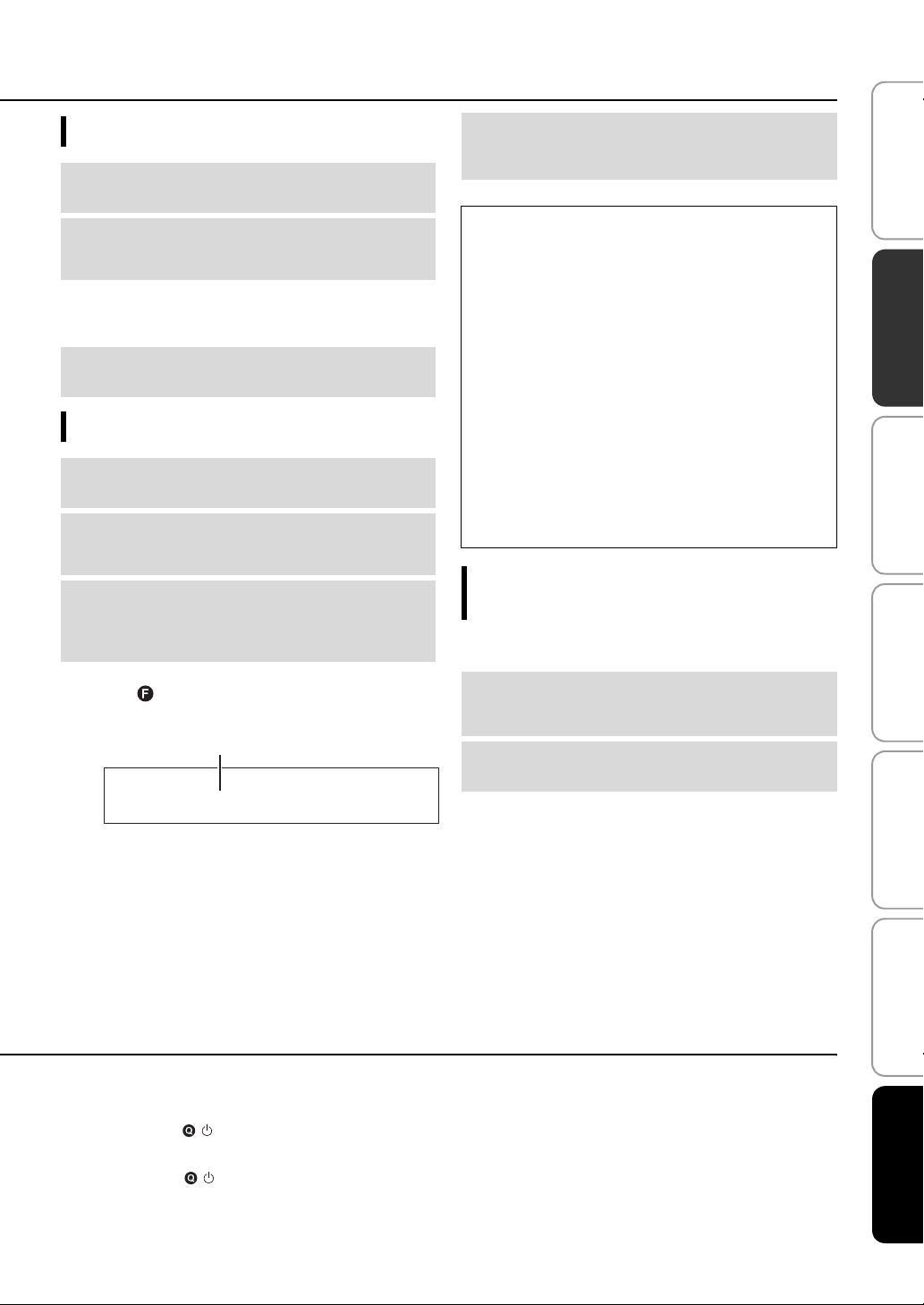
PLAYBACK
Playback features
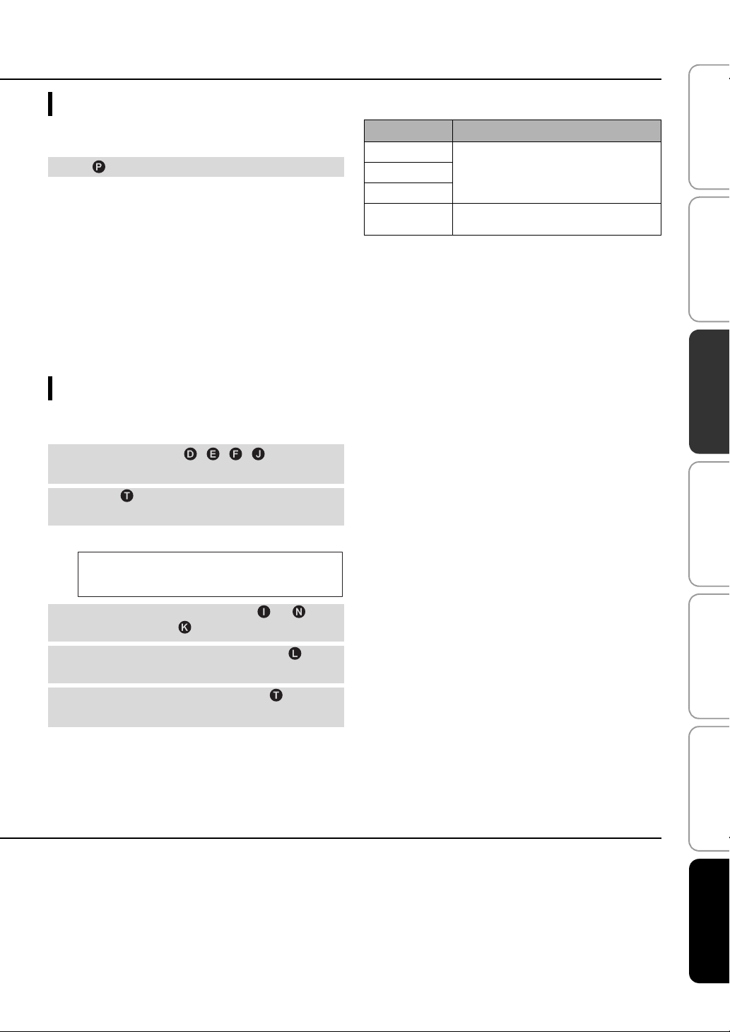
Basic operation for playback
Press key to turn on this unit.
1
Turn on components (TV, Blu-ray disc
2
player, game console, etc.) connected to
this unit.
Select a component you want to listen to
3
by pressing the input selector key ( , ,
) corresponding to the connection of
external components.
For example, when playing back a Blu-ray disc player
connected to HDMI IN 1 jack, select HDMI1 by pressing
input selector key as shown below.
Input source name
HDMI1
1) y
When audio is output from both TV speaker and this unit, mute the TV
sound.
2) y
To mute the sound
Press MUTE key. While the mute function is activated, the VOL
indicator on the front panel display flashes. To resume the volume, press
MUTE key again or press VOLUME +/- key.
Play back component selected in step 3.
4
Press VOLUME +/- key to adjust the
5
volume.
Press SUBWOOFER +/- key to adjust
the subwoofer.
Select surround mode or stereo mode and
6
set your sound preferences. (☞p. 21)
Press key to turn this unit to standby mode.
3) Note
When sound input to HDMI IN is output from the TV, the volume level
does not change even if you press VOLUME +/- key or MUTE
key.
y
4)
• The subwoofer volume in this unit can be adjusted separately from the
volume.
• Lowering the subwoofer volume is recommended at night.
1) 2) 3)
4)
20 En
Enjoying sound with your preference
Switching stereo/surround sound
When playback is in stereo sound.
Press STEREO key to switch to stereo
mode.
When playback is in surround sound.
Press SURROUND key to switch to surround
mode.
Playing back digitally compressed formats (MP3, WMA, etc.) with enriched sound (Compressed Music Enhancer)
Play back digitally compressed format such as MP3 and WMA
emphasizing bass and treble extended dynamically.
Press ENHANCER key to turn the function
on/off.
5)
Playback features
Automatic volume level adjustment (UniVolume)
While watching the TV, compensate the excessive volume differences
to make it easier to hear during the following cases.
• When switching the channel
• When a TV program changed to commercial
• When one program is finished and another program started
Press UNIVOLUME key to turn the function
on/off.
6)
Volume balance adjustment
Use this feature to adjust the volume balance for each channel
during playback.
Press CH LEVEL key.
7)
1
Press U/ V key to select adjustable
2
channel from the followings.
Left LV: Front left
Right LV: Front right
Center LV: Center
Sur.L Lv: Surround left
Sur.R Lv: Surround right
SWFR Lv: Subwoofer
PREPARATION
INITIAL SETTINGS SETTINGS
CONNECTION/
5) y
• The default setting is “On” for DOCK input, and “Off” for other
inputs.
• Compressed Music Enhancer does not work when the source is
following digital audio signal,
– Dolby TrueHD, DTS-HD Master Audio, etc.
– Signal that sampling rate is more than 48 kHz.
6) y
• The default setting is “Off”.
• To set the UniVolume to “Off”, press UNIVOLUME key.
• We recommend turning off the UniVolume function during playback
of music.
7) y
Refer to “Volume level of each channel with test tones (☞p. 37)” when
adjusting the test sound.
When My Surround is selected:
CenterLv: Center
SurLR Lv: Surround left and right
SWFR LV: Subwoofer
Press Y/Z key to adjust the volume.
8)
3
Adjustable range: -10.0 dB to +10.0 dB
Press CH LEVEL key to exit from the
4
menu.
8) y
Example of volume balance
• If you have problems hearing words: Select Center Lv (center) to
increase the level.
• When the sound does not seem like surround sound: Select Sur.L LV
(surround left) and Sur.R LV (surround right) to increase the level.
• The volume of subwoofer also can be adjusted by using
SUBWOOFER +/- key.
TROUBLESHOOTING
ABOUT THIS UNIT EnglishPLAYBACK
21 En
Playback features
Enjoying realistic surround sound (CINEMA DSP)
Playback surround sounds using Yamaha’s exclusive CINEMA
1)
DSP.
Press SURROUND key to switch to
1
surround mode.
Press the desired CINEMA DSP key
2
repeatedly.
The CINEMA DSP category name appears in the front
panel display and the CINEMA DSP indicator (☞ p. 47)
lights up.
Sci-Fi
This program clearly reproduces dialogs and special sound
effects of the latest science fiction films and lets you feel a
broad and expansive cinematic space.
Adventure
This program reproduces the thrilling environment of the
latest action films and lets you feel the dynamic and
excitement of fast-moving scenes.
Spectacle
This program reproduces the wide and grand environment and
lets you have added impressions on spectacular scenes with
strong visual impacts.
2) 3)
MOVIE
1) y
CINEMA DSP
This unit is equipped with a Yamaha CINEMA DSP (digital sound field
processing) chip containing several sound field programs used to
enhance your playback experience. Most of the CINEMA DSP programs
are precise digital recreations of actual acoustic environments of famous
concert halls, music venues, and movie theaters.
2) y
The CINEMA DSP programs are not available in the following
conditions.
22 En
• HD audio signals are being played back on a Blu-ray disc.
• Audio signals with sampling frequency of higher than 96 kHz are
being played back.
• When using My Surround function (☞p. 23).
• When playing back in stereo mode.
3) y
This unit automatically memorizes the settings assigned to each input
source. When you select another input, the unit automatically recalls the
last settings for the selected input.
MUSIC
Music Video
This program produces a vibrant environment and lets you
feel as if you are at an actual jazz or rock concert.
Concert Hall
This program creates a rich surround effect of a large round
concert hall with a great deal of presence, emphasizing the
extension of sounds, and lets you feel as if you are seated
close to the center of the stage.
Jazz Club
This program recreates the acoustic environment of “The
Bottom Line”, a famous jazz club in New York once and lets
you feel as if you are seated right in front of the stage.
ENTERTAINMENT
Sports
This program reproduces the energetic environment of live
sports broadcasting, converging a commentator’s voice on the
center and broadening the overall atmosphere of the stadium,
and lets you feel as if you are seated at an actual stadium or a
ball park.
Talk Show
This program reproduces excitement of live talk shows. It
enhances the ambience of gaiety while keeping the
conversations at a comfortable volume.
Drama
This program stables reverberations that match a wide range
of movie genres from serious dramas to musicals and
comedies, and offers an optimum 3D feeling, reproducing
effects tones and background music softly but cubically
around clear words.
Game
This program is suitable for role-playing and adventure
games. It utilizes the sound field effects for movies to
represent the depth and spatial feeling of the field during play,
while offering movie-like surround effects in the movie
scenes in the game.
Mch Stereo
This program downmixes multi-channel source to 2 channels
and then outputs the sound from all speakers and produces
stereo sounds in wide range. It is ideal for background music
at parties, etc.
Playback features
OFF (DSP Off)
Sur.Decorder (surround decorder)
This program plays back surround sound without CINEMA
DISP sound field effect.
Changing the audio output method for surround playback
You can set the number of beam output channels and audio
output method.
Press SETUP key.
1
Use U / V key and ENTER key to
2
select “Sound Setup”.
Use U / V key and ENTER key to
3
select “Sound Out”.
Use U / V key and ENTER key to
4
select “Ch Out”.
Press Y/Z key to select the number of
5
output channels.
Selectable item: 5.1ch, 7.1ch, Auto ch*
Press V key to select “Sur.”
4)
6
Press Y/Z key to select the desired
7
audio output method.
Selectable item:
(When 5.1ch is selected) 5Beam, St+3Beam,
3Beam, My Sur.
(When 7.1ch is selected) 5Beam+2, St+3Beam2,
3Beam, My Sur.
To exit the menu, press SETUP key.
5)
8
PREPARATION
INITIAL SETTINGS SETTINGS
TROUBLESHOOTING
ABOUT THIS UNIT EnglishPLAYBACK
CONNECTION/
4) y 5) y
• The default settings are marked with “*”.
• When “Auto ch”(automatic) is set.
When the input signal is 2ch/5ch 5.1ch output
When the input signal is 6.1/7.1ch 7.1ch output
“Headphone” is displayed when headphones are connected, and the
setting is cannot be changed.
Continued to the next page.
23 En

Playback features
■ Selectable item for “Sur. (surround)”
Beam modes for “5.1ch” Beam modes for “7.1ch”
For enjoying
surround sound
effects on the movie,
etc. to the fullest
For watching live
recordings on a
Blue-ray disc
5 Beam (5 Beam)
Outputs sound beams
from the front right and
left, center, and surround
right and left channels.
St+3Beam (Stereo+3Beam)
5Beam+2 (5Beam Plus2)
Outputs sound beams
from the front right and
left, center, and surround
back right and left
channels. Surround right
and left channel sources
are mixed into the front
right and left and
surround back right and
left channels.
St+3Beam2 (St+3Beam Plus2)
For enjoying movies
with the whole
family, or when the
listening position is
close to the backside
of the wall.
For small listening
area or when
surround sound
effects are
insubstantial due to
the listening room
conditions.
Outputs normal sound from the front right and left
channels and sound beams from the center and
surround right and left channels.
3 Beam (3 Beam)
Outputs sound beams from the front right and left and center channels.
Other channel sources are mixed into the front right and left channels.
My Sur. (My Surround)
For the full effect of My Surround, your listening position must face toward the front of this unit.
Even surround sound effects are insubstantial with other setting, you can enjoy sound with surround
effects.
Outputs normal sound from the front right and left
channels and sound beams from the center and
surround back right and left channels. Surround
right and left channel sounds are output by using
front right and left channel sound and surround
back right and left sound beams.
24 En
Surround decoder setting
When this unit plays back 2-channel or 5.1-channel sources in
surround mode, surround decoder enables them playback for 7.1-
1)
channel.
switching the decoder.
You can enjoy a variety of surround sound effects by
2)
Playback features
PREPARATION
Select and set “Sur.Dec.Mode” in the option
menu.
Refer to “Configuring settings for each input source (Option
menu)” on page 27 for the operation of option menu.
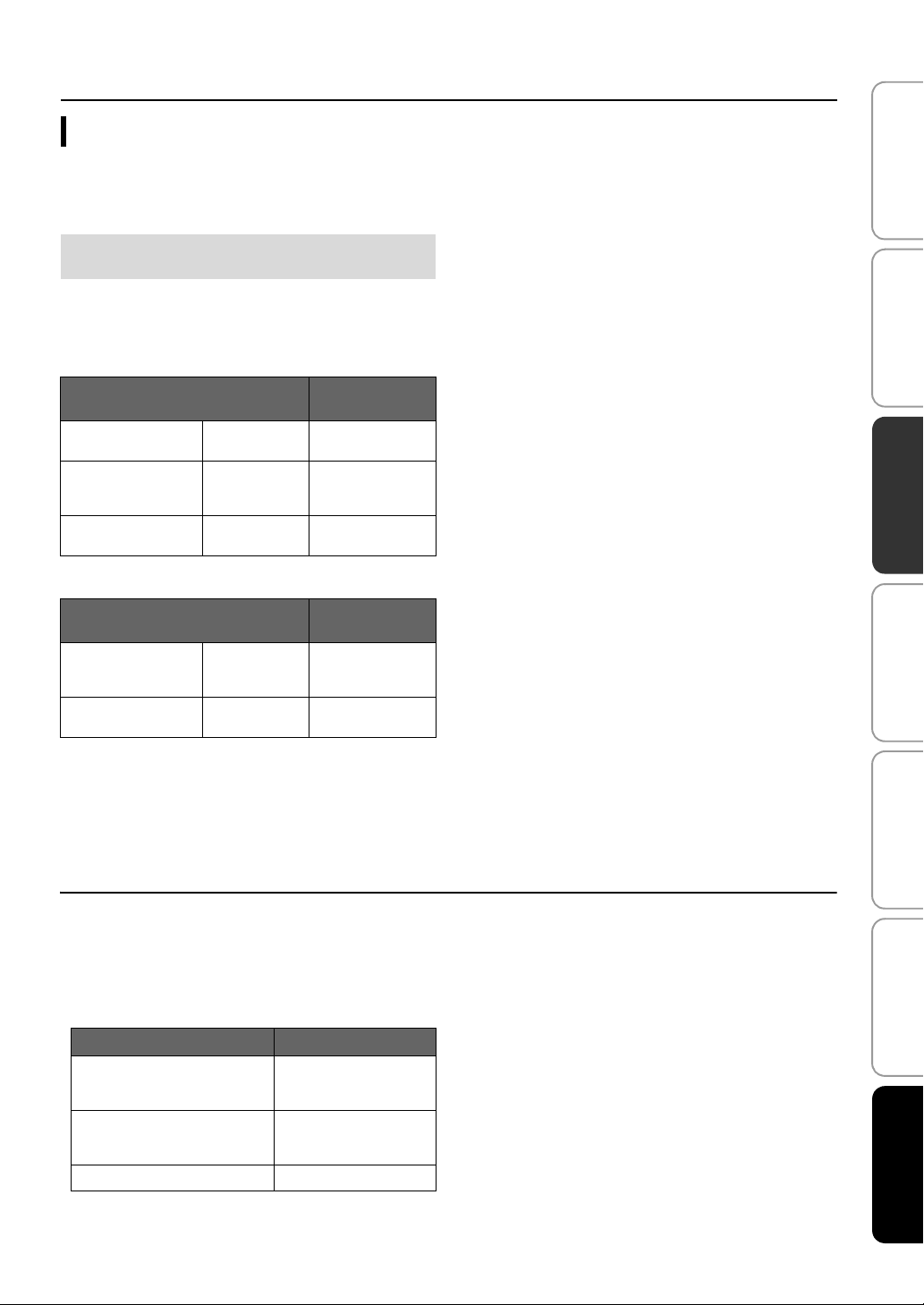
Available decoders and recommended sources
2ch 5ch
Decoder
Pro Logic (Dolby Pro
Logic)
PLII (Dolby Pro Logic
II)
Neo:6 (DTS Neo:6) Cinema
Movie
Music
Game
Music
2ch 7ch
Decoder
PLIIx (Dolby Pro Logic
IIx)
Neo:6 (DTS Neo:6) Cinema
Movie
Music
Game
Music
– All sources
Recommended
source
Movies
Music
Games
Movies
Music
Recommended
source
Movies
Music
Games
Movies
Music
INITIAL SETTINGS SETTINGS
TROUBLESHOOTING
CONNECTION/
1) y
About the surround decoder Playing back 5.1-channel
sources
When “Ch Out” (channel output) is set to “7.1ch”, this unit decodes 5.1channel sources and then playback them in up to 7.1-channel surround
(☞p. 23). One of the following decoders is automatically selected
depending on the input signals.
5.1ch input source Decoder
PCM, Dolby Digital, Dolby Digital
EX, Dolby TrueHD, Dolby Digital
Plus
DTS Digital, DTS-ES matrix, DTSHD Master Audio, DTS-HD High
Resolution Audio
DTS-ES discrete DTS-ES discrete
Dolby Pro Logic IIx Movie/
Music
DTS-ES matrix
2) y
• The decoders are available only when surround playback is selected.
• Available decoders vary depending on the “Ch Out” setting (☞p. 24).
• During stereo playback (☞p. 21) or using My Surround function
(☞p. 23), surround decoder is invalid.
25 En
ABOUT THIS UNIT EnglishPLAYBACK
Playback features
Using useful features
Listening with headphones
Insert a headphone plug to the PHONES jack
(☞p. 46) of this unit.
The surround sound using headphones
With newly-developed 7.1 ch headphone surround
technology, you can enjoy surround and stereo sound using
headphones same as speaker. (☞p. 21) When using
headphones, changing CINEMA DSP (☞p. 22) is also
available.
1)
1) y
• The headphone volume, tone control, and LFE level can be set
separately with speaker setting.
• If too much bass is heard while playing back 5.1 or 7.1 channels
containing LFE channel (0.1ch), it may be improved by decreasing
the LFE level. (☞p. 36)
26 En
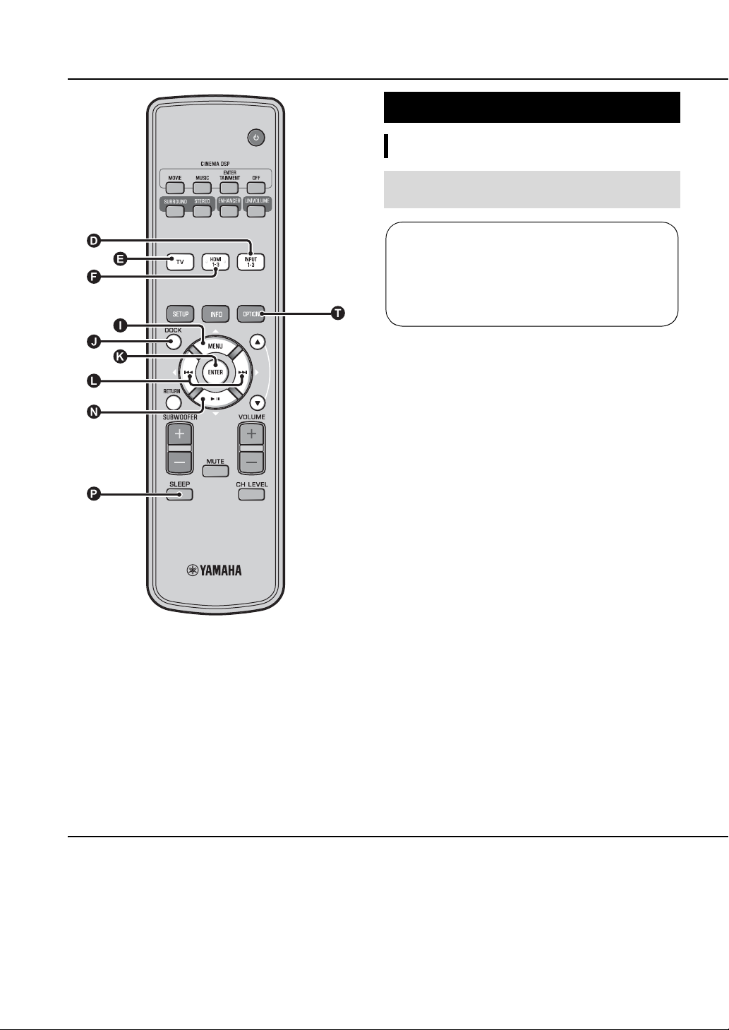
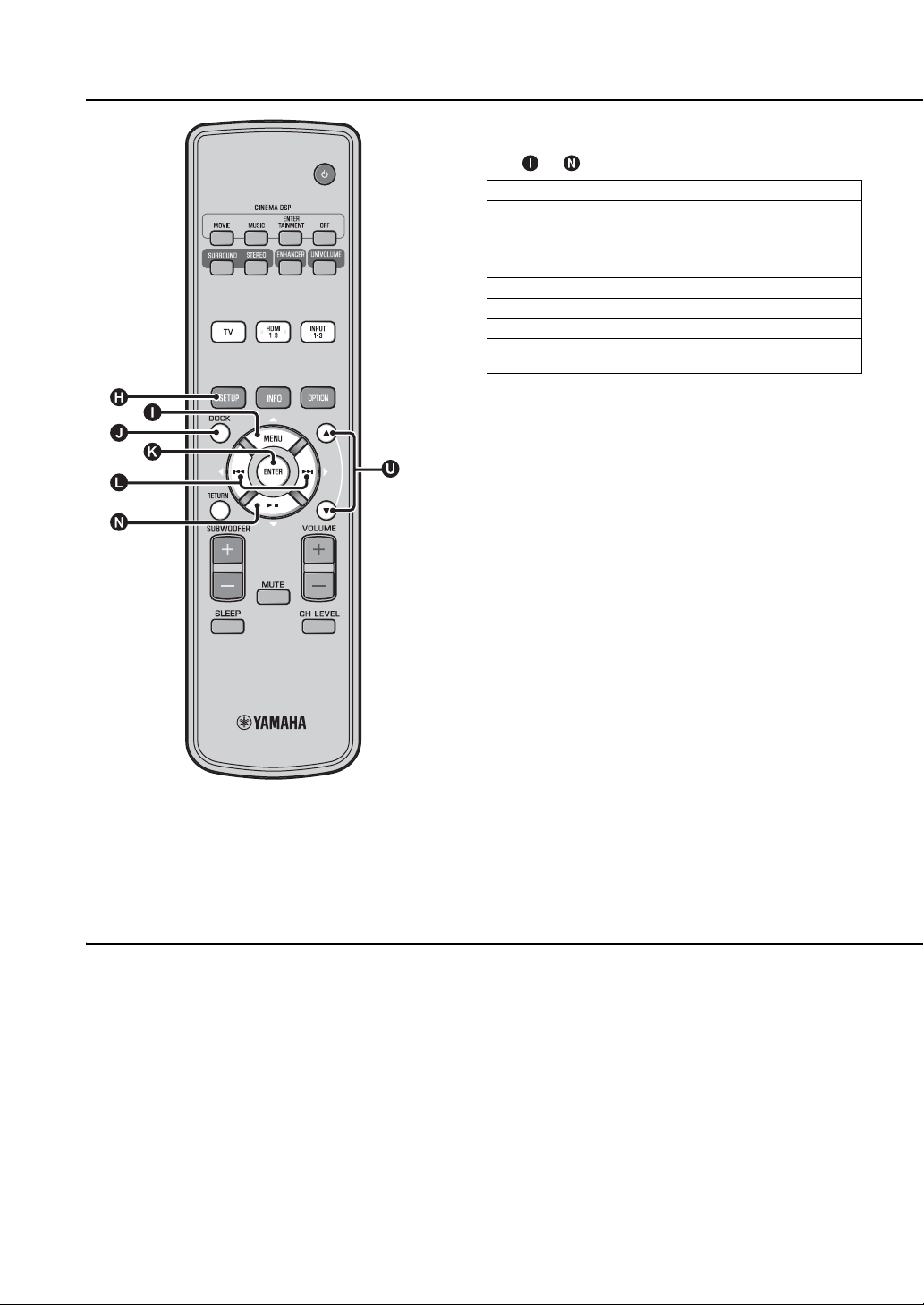
Sleep timer/auto power down function
Use this feature to automatically set this unit to the standby mode
after a specified period of time.
Press SLEEP key repeatedly.
Switching the time it takes to switch to standby mode. The
SLEEP indicator (☞p. 47) flashes in the front panel display.
The SLEEP indicator in the front panel display lights up and the
sleep timer is set.
Selectable item: Sleep 120 min., Sleep 90 min., Sleep
60 min., Sleep 30 min., AutoPowerDown, Off
■ Auto power down function
When AutoPowerDown is set, the unit is turned to standby mode
automatically after 10 minutes from the selected input source is
turned off or in standby mode. This function is useful to prevent
you from forgetting to turn off the unit.
2)
3)
Settings for each input source (Option menu)
Set according to each input (TV/HDMI1-3/INPUT1-3/DOCK).
Available menu items vary depending on the selected input.
Press input key ( , , , ) to select
1
the input you want to change the setting.
Press OPTION key.
2
The option menu is displayed on the front panel display.
; Volume Trim
Select the items by pressing U/ V
3
key, then press ENTER key.
Playback features
Option menu items
The following menu items are provided for each input.
Input source Menu items
HDMI1-3 Volume Trim, Decoder Mode, Sur. Dec. Mode,
TV
INPUT1-3
DOCK
The option menu items are listed below. These settings are
applied to the currently selected input source. The default settings
are marked with “*”.
Signal Info
Volume Trim, Sur. Dec. Mode, Connect,
Disconnect, Pairing, Interlock
4)
■ Adjusting input level of each jack
(Volume Trim)
Adjust the input level for each jack to compensate for variations
in volume between different input devices.
Adjustable range: -6.0 dB to 0.0 dB* to +6.0 dB
■ Switching the audio signal to play back
(Decoder Mode)
Use to select digital audio signals for playback.
Selectable item: Auto*, DTS
Auto: This unit automatically selects the audio signal for
playback. Normally select this mode.
DTS: This unit plays back only DTS signal.
■ Setting the surround decoder (Sur. Dec.
Mode)
Refer to “Enjoying sound with your preference” (☞p. 21) for
details.
PREPARATION
INITIAL SETTINGS SETTINGS
TROUBLESHOOTING
CONNECTION/
Change setting value by pressing Y/Z
4
key.
To exit the option menu, press OPTION
5
key.
2) y
• The sleep timer setting is canceled if this unit is set to the standby
mode or “Off” is selected.
• When AutoPowerDown is set, SLEEP indicator does not light up
while the input source component is turned on.
3) y
• If the unit is operated during the 10 minutes before entering standby
mode, the unit does not enter standby mode until 10 minutes after the
latest operation.
ABOUT THIS UNIT EnglishPLAYBACK
• AutoPowerDown cannot be selected when:
– analog (INPUT3) or DOCK is selected.
– TV or HDMI1-3 is selected and HDMI control function is on.
4) y
For details on Interlock, refer to “Playing back iPod/iPhone (☞p. 29)”.
For details on Connect, Disconnect and Pairing, refer to “Playing back
Bluetooth components (☞p. 30)”.
27 En
Playback features
■ Displaying the input signal information
(Signal Info)
Press U/ V key to change the following information.
Format Digital audio format
Channel The number of channels included in input signal
Sampling Sampling frequency for digital input signal
Bitrate Bitrate per second of input signal
HDMI In HDMI video signal resolution
HDMI Message When error occurs with HDMI (displayed only
(front/surround/LFE (low frequency sound
effects))
Display example: [3/2/0.1] Front 3ch,
Surround 2ch, LFE for input signal
when error is occurred.)
1)
1) y
If the input signal includes channels that cannot be displayed in the
format shown in the display example, the total number of channels will
be displayed, as in “5.1ch”.
28 En
 Loading...