

Yamaha YMC-700, YMC-500 User Manual

Media Controller
YMC-700
U
YMC-500
OWNER’S MANUAL
Contents
CONTENTS
IMPORTANT
Before installing this unit, be sure to read the supplied
Quick Start Guide.
INTRODUCTION
Features ................................................................... 2
Notices ....................................................................... 3
Supplied accessories .................................................. 3
Controls and functions ........................................... 4
Front/side/top panel ................................................... 4
Remote control........................................................... 5
SETUP
Connections ............................................................. 6
Remote control connection .................................... 8
Placing speakers...................................................... 9
Initial Setup ........................................................... 10
Before starting the Initial Setup ............................... 10
Step 1: Auto Speaker Setup ..................................... 10
Step 2: TV Remote Control Setup ........................... 13
Step 3: Source Device Setup.................................... 14
BASIC OPERATION
General operation ................................................. 18
Screens and operation .............................................. 18
Basic playback operation......................................... 19
Regular pop up menu items ..................................... 19
Enjoying the contents on an external devices .... 20
Watching/listening to the source content................. 20
Using the remote control to operate external
devices from the playback screen ........................ 21
Using virtual remote control to operate external
devices ................................................................. 21
Listening to FM Radio ......................................... 22
Automatic station preset .......................................... 23
Recalling a preset station ......................................... 23
Frequency tuning ..................................................... 23
Editing the station preset list.................................... 23
Listening to music stored on your PC
(YMC-700 only) or USB device ....................... 24
Before enjoying the contents on your PC
(YMC-700 only) .................................................. 25
Playing music files................................................... 25
Repeat play and shuffle play.................................... 25
Viewing photos stored on your PC
(YMC-700 only) or USB device........................26
Viewing photos ........................................................ 27
Slide show................................................................ 27
Shuffle browsing...................................................... 27
Using the photos as a screen saver .......................... 27
Enjoying contents stored on your iPod ...............28
Listening to music contents ..................................... 29
Watching video contents ......................................... 29
Repeat play and shuffle play.................................... 29
Listening to Internet Radio
(YMC-700 only).................................................30
Listening to the Rhapsody
®
service
(YMC-700 only).................................................32
Useful functions....................................................... 33
Enjoying Bluetooth™ components ......................35
Pairing...................................................................... 35
ADVANCED OPERATION
Setup menu ............................................................36
Setup menu tree ....................................................... 36
Initial Setup.............................................................. 37
Speaker menu .......................................................... 37
Sound menu ............................................................. 38
Input menu ............................................................... 39
Network menu (YMC-700 only) ............................. 40
Rhapsody
Remote Control menu.............................................. 42
Option menu ............................................................ 43
Signal Information ................................................... 44
Update menu............................................................ 44
®
Information menu
(YMC-700 only).................................................. 41
ADDITIONAL INFORMATION
Troubleshooting.....................................................45
Glossary..................................................................51
Information on audio/video jacks and
cable plugs ........................................................... 53
Information on HDMI™.......................................... 54
Specifications .........................................................55
Quick reference .....................................................56
SETUPINTRODUCTION
OPERATION
BASIC
OPERATION
ADVANCED
INFORMATION
ADDITIONAL
■ About this manual
• This manual describes how to operate this unit using a remote control. Most operations are also available using the buttons on the
top panel.
• y indicates a tip for your operation.
• Notes contain important information about safety and operating instructions.
• This manual is printed prior to production. Design and specifications are subject to change in part as a result of improvements, etc.
In case of differences between the manual and the product, the product has priority.
1 En
FEATURES
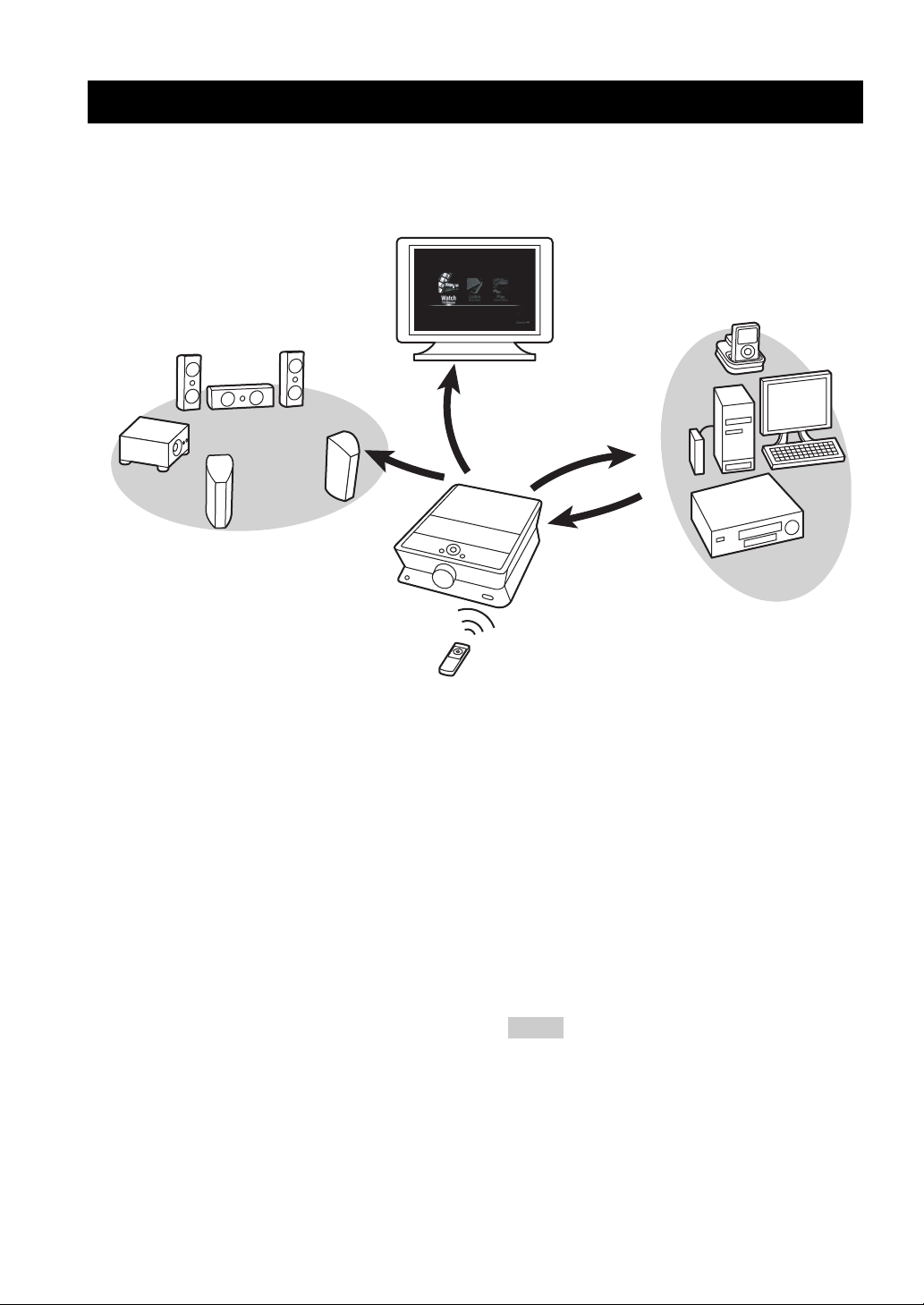
Features
Thank you for your purchasing a Yamaha neoHD. The neoHD can control all of your devices through a simplified remote
control unit and stylish/intuitive graphical user interface. Enjoy the Yamaha neoHD experience.
Stylish and Intuitive
Graphical User Interface
Variety of
Input Sources
Surround Sound
Video
Audio
Simplified
Remote Control
Easy and intuitive operation
◆ Sophisticated graphical user interface
◆ Power control of connected TV and audio/video components
◆ Physical and virtual remote control to control playback of
connected audio/video components
Audio features
◆ Decoding and mixing of multi-channel sources (up to
7.1-channel input and 5.1-channel output)
◆ Proprietary Yamaha technology for the creation of sound
fields (DSP Program)
◆ AIR SURROUND XTREME for 2.1-channel speaker layout
◆ Compressed Music Enhancer mode
◆ YPAO (Yamaha Parametric room Acoustic Optimizer)
technology for Auto Speaker Setup
◆ Adaptive Dynamic Range Controlling to improve listenability
at low volumes
HDMI™ (High-Definition Multimedia Interface)
◆ HDMI interface for standard, enhanced or high-definition
video as well as multi-channel digital audio based on HDMI
version 1.3a (HDMI is licensed by HDMI Licensing, LLC.)
– Automatic audio and video synchronization (lip sync)
information capability
– Deep Color video signal (30/36 bit) transmission capability
– “x.v.Color” video signal transmission capability
– High resolution video signal capability
– High definition digital audio format signal capability
◆ HDCP (High-bandwidth Digital Content Protection System)
licensed by Digital Content Protection, LLC.
◆ Analog to HDMI video up conversion
Power
Control
Power and
Playback
Control
Audio
and
Video
Digital audio decoders
◆ Dolby TrueHD, Dolby Digital Plus, Dolby Digital decoder
◆ DTS 96/24, DTS decoder
Radio tuner
◆ FM tuning capability, 40-station preset tuning
DOCK terminal
◆ DOCK terminal to connect a Yamaha iPod universal dock
(such as the YDS-11, sold separately) or Bluetooth wireless
audio receiver (such as the YBA-10, sold separately)
Network (YMC-700 only) and USB features
◆ NETWORK port and Wi-Fi to connect a PC or access Internet
Radio and Rhapsody
◆ DHCP automatic or manual network configuration
◆ USB port to connect a USB storage device (not including
USB hard disk drives)
®
via LAN
Notes
• This unit supports USB mass storage class devices (FAT 16
or FAT 32 format).
• This unit supports audio files in following format: WAV
(PCM format only), MP3, WMA, MPEG-4 AAC, and
FLAC.
• For FLAC, the unit only supports bit lengths of 16 bits.
Frequencies of up to 48 kHz are supported.
• This unit supports image files in the JPEG format.
2 En
Features
Notices
Manufactured under license from Dolby Laboratories.
Dolby, Pro Logic and the double-D symbol are trademarks of
Dolby Laboratories.
Manufactured under license under U.S. Patent #’s: 5,451,942;
5,956,674; 5,974,380; 5,978,762; 6,226,616; 6,487,535 & other
U.S. and worldwide patents issued & pending. DTS and DTS
Digital Surround are registered trademarks and the DTS logos,
Symbol and DTS 96/24 are trademarks of DTS, Inc. © 1996-2008
DTS, Inc. All Rights Reserved.
TM
iPod
“iPod” is a trademark of Apple Inc., registered in the U.S. and
other countries.
MPEG Layer-3 audio coding technology licensed from
Fraunhofer IIS and Thomson.
“HDMI”, the “HDMI” logo and “High-Definition Multimedia
Interface” are trademarks, or registered trademarks of HDMI
Licensing LLC.
x.v.Color™
“x.v.Color” is a trademark of Sony Corporation.
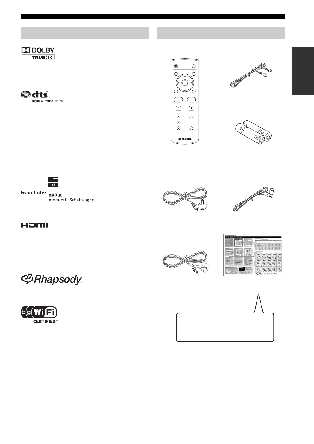
Supplied accessories
Check that you received all of the following accessories.
TV
POWER
POWER
MENUGUIDE
ENTER
EXIT
PREV.
CONTROL BACK
CH VOL
MUTEPAGE
Remote control
(☞ P. 5 )
YPAO Microphone
(YPAO Mic)
(☞ P. 11)
Power cable
(☞ P. 6 )
Battery
(AAA, LR03) ×2
(☞ P. 5 )
Indoor FM antenna
(☞ P. 7 )
INTRODUCTION
Rhapsody and the Rhapsody logo are registered trademarks of
RealNetworks, Inc.
The Wi-Fi CERTIFIED Logo is a certification mark of the Wi-Fi
Alliance.
Windows XP, Windows Vista, Windows Media Audio, Windows
Media Connect and Windows Media Player are either registered
trademarks or trademarks of Microsoft corporation in the United
States and/or other countries.
This product is manufactured under license from Allegro
Software Development Corporation. ©1996-2008 Allegro
Software Development Corporation. All rights reserved.
IR flasher (3 m) ×2
(☞ P. 8 )
Before installing this unit, be sure
to read the Quick Start Guide.
Quick Start Guide
(☞ P. 14)
IMPORTANT
3 En
CONTROLS AND FUNCTIONS
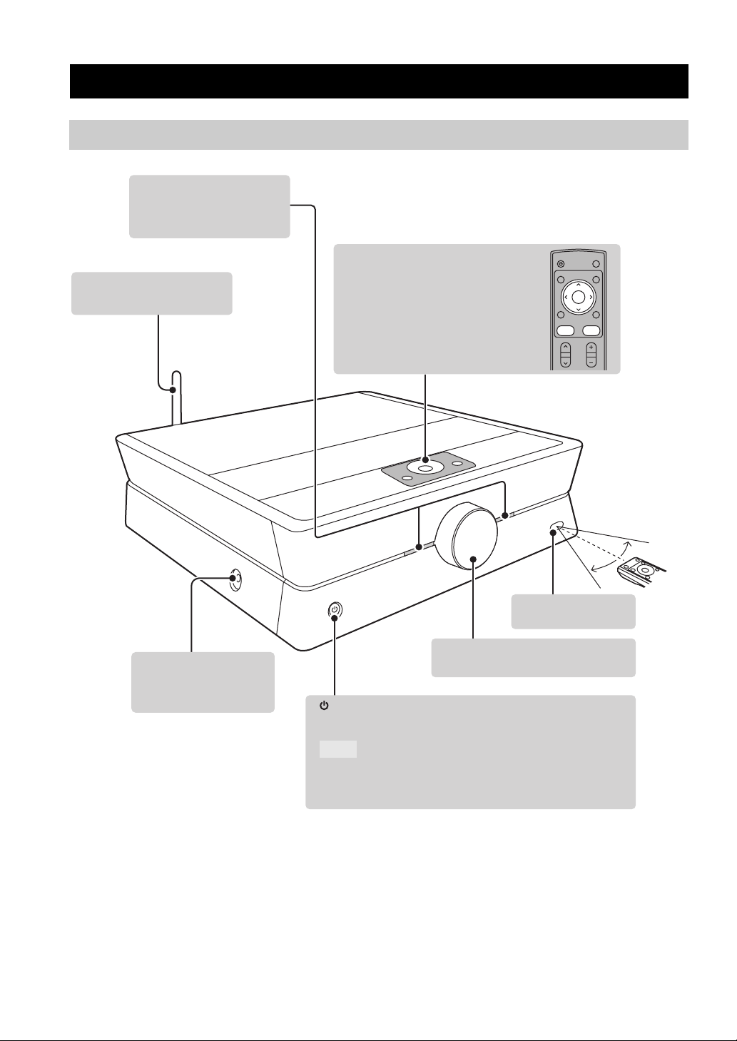
Front/side/top panel
Power indicator
Lights up when this unit is
turned on.
WIRELESS antenna
(YMC-700 only)
Controls and functions
CONTROL,
u / d / j / i,
ENTER,
BACK
These buttons work in the same way
as the corresponding buttons on the
remote control. (☞ P. 5)
POWER
ENTER
PREV.
CONTROL BACK
CH VOL
TV
POWER
MENUGUIDE
EXIT
YPAO Mic jack
Used for Auto Speaker
Setup. (☞ P. 10)
Within
6 m (20 ft.)
30°
30°
Remote control
sensor
Volume knob
Controls the volume level.
Turns on this unit or sets it to the standby mode.
Note
In the standby mode, this unit consumes a small amount of power
in order to receive infrared-signals from the remote control.
4 En
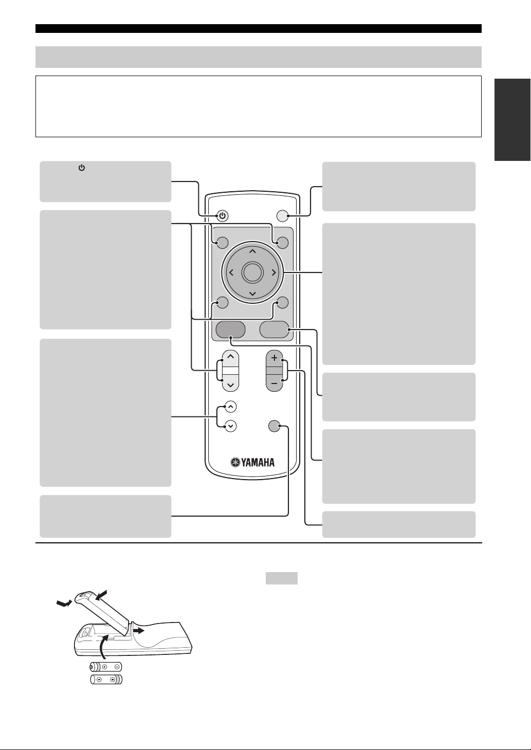
Remote control
2
Controls and functions
IMPORTANT
• To control TV and source components, you need to make remote control connections (☞ P. 8) and set the remote
control code (☞P. 13, 14).
• To control a TV or source component, aim the remote control at the remote control sensor of this unit.
Operating instructions for activities (☞P. 18-35)
POWER
Turns on this unit or sets it to the
standby mode. (☞P. 19, 43)
POWER
TV
POWER
TV POWER
Turns on the TV or sets it to the
standby mode individually while this
unit is turned on.
• MENU
• GUIDE
• EXIT
• PREV.
• CH u / d
These buttons work differently
depending on the currently
selected source component.
(☞ P. 21)
PAG E u / d
When the playback screen is
displayed
These buttons work differently
depending on the currently
selected source component.
(☞ P. 21)
When the virtual remote control
or contents list is displayed
These buttons scroll up/down the
virtual remote control or contents list.
ENTER
PREV.
CONTROL BACK
CH VOL
MUTEPAG E
MENUGUIDE
EXIT
j / i / u / d /ENTER
When the GUI screen or the
virtual remote control is
displayed
Move the highlight with
j / i / u / d and
select it with ENTER.
When the playback screen is
displayed
These buttons work differently
depending on the currently selected
source component. (☞P. 21)
BACK
Returns to the previous menu level.
Press and hold to return to the top
menu level.
CONTROL
Turns on or off the pop up menu and
virtual remote control.
Press and hold to return to the top
menu level.
Turns on this unit. (☞ P. 43)
MUTE
Mutes the audio output of this
unit.
VOL +/–
Controls the volume level of this unit.
INTRODUCTION
■ Installing batteries in the remote control
1
4
2
3
Batteries (supplied)
Make sure you insert the batteries as
indicated by the polarity markings
(+ and –).
Notes
• Do not use an old battery together with a new one.
• Do not use different types of batteries (for example, alkaline
and manganese) together.
• If the batteries run out, immediately remove them from the
remote control to prevent an explosion or acid leak.
• Dispose of the batteries according to the regional regulations.
• If a battery starts leaking, dispose of it immediately. Be careful
not to let leaking battery acid come into contact with your skin
or clothing. Before inserting new batteries, wipe the
compartment clean.
5 En
USB
FRONT SURROUND
SUB
WOOFER
CENTER
REMOTE CONTROL
SPEAKERS
OUTPUT
NETWORK
AUDIO IN
HDMI OUT
OUT
IN
AC IN
1
2
1 2
3
3
R L
R
LR L
3
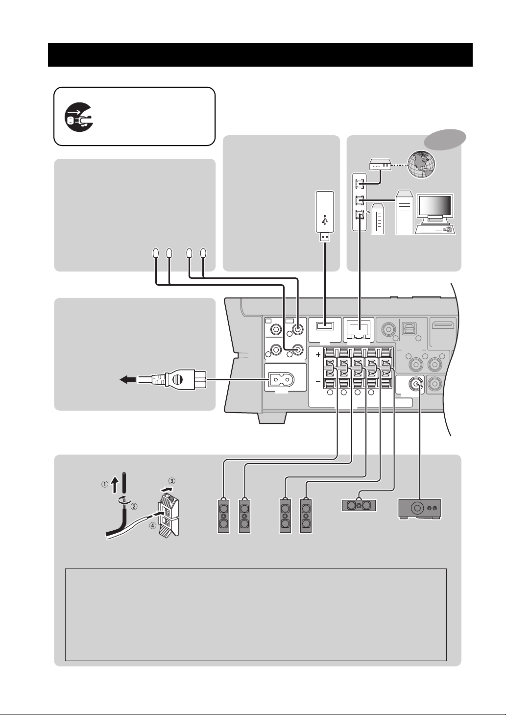
Make sure that this unit and
other components are
unplugged from the AC wall
outlets.
Remote control
Connect the supplied IR flashers to
the REMOTE CONTROL OUT 1 and 2 jacks.
y
You can attach the IR flashers to any of the
components used in conjunction with this
unit because the same signal is output from
the REMOTE CONTROL OUT 1, 2, and 3 jacks.
☞ P. 8
IR flashers
(supplied)
Power cable
Connections
USB storage device
Be sure to insert in the
proper direction.
You can connect
or disconnect USB
storage devices
while this unit is
turned on.
Supported devices
☞ P. 2
Wired network
Modem
WAN
LAN
Setup ☞ P. 25, 40
Use CAT-5 or higher
STP cable
YMC-700
PCRouter
only
Power cable
(supplied)
To A C
wall outlet
Speaker cables
Speakers and Subwoofer
Center
Speaker
Speaker layout ☞ P. 9
Front
Speakers
Surround
Speakers
Also refer to the supplied Quick Start Guide.
Caution
· Be sure to use speakers with 6 ohm or higher impedance.
· Do not let the bare speaker wires touch each other or do not let them touch any metal part of this unit.
This could damage this unit and/or speakers.
· Be sure to connect the left channel (L), right channel (R), “+” and “–” properly. If the connections are
faulty, this unit cannot reproduce the input sources accurately.
·
If speakers have color coded terminals, match the color. If not, connect the striped (grooved, etc.)
cable to the “+” terminals of this unit and your speaker and connect the plain cable to the “
6 En
Subwoofer
cable
Subwoofer
–
” terminals.
Connections
SURROUND
SUB
WOOFER
CENTER
KERS
OUTPUT
NETWORK
AUDIO IN
HDMI OUT HDMI IN
VIDEO IN
WIRELESS
ANTENNA
FM
75
Ω
UNBAL.
DOCK
1
1
2
1
2
2
3
3
3
R L
R
L
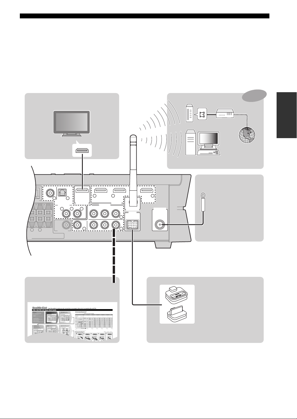
TV
TV
HDMI IN
HDMI cable
Wireless network
Modem
WAN
Router
PC
Setup ☞ P. 25, 40
FM antenna
Indoor FM antenna (supplied)
If you experience poor
reception quality, install
an outdoor antenna.
Consult the nearest
authorized Yamaha dealer
or service center about
outdoor antennas.
YMC-700
only
SETUP
Audio/Video components iPod dock/Bluetooth receiver
Connect your audio/video components
to these jacks. Refer to the supplied
Quick Start Guide for connections.
Yamaha iPod universal
dock or Bluetooth wireless
audio receiver
Connect a Yamaha iPod
universal dock (such as
the YDS-11, sold separately)
or Bluetooth wireless
audio receiver (such as
the YBA-10, sold separately)
using its dedicated cable.
7 En
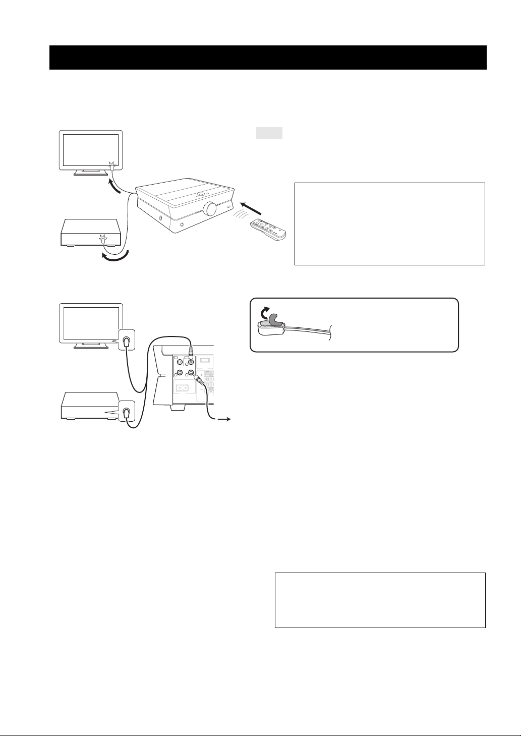
Remote control connections
T
E
You can control your TV and the components connected to this unit using the remote control of this unit by connecting
the IR flashers between this unit and the components, and by setting the IR codes. You can also turn on or off the TV and
the components in conjunction with the operation of this unit.
TV
Note
While this unit is turned on, this unit passes all remote control
codes (of the TV and source devices) input at the remote control
sensor to the TV and the devices via IR flashers.
About the remote control codes
Source device
■ Connections
TV
SENSOR
This unit equips built-in remote control codes for most
functions of many audio/video components. The
remote control codes can be “learned”, assigning them
to the remote control of this unit or to the virtual
remote control (☞P. 21). The unit transmits the proper
codes to the different devices through the IR flasher.
Peel off the wax paper
before attaching the flashers.
OUT
IN
1
USB
3
2
REMOTE CONTROL
Source device
SENSOR
AC IN
R
FRON
SP
To o t her
source devices
■ Settings
Make the following settings.
• The IR setting for your TV
Initial Setup ☞P. 10, Setup Menu ☞P. 4 2
• The IR settings for the components connected to this
unit
Initial Setup ☞P. 10, Setup Menu ☞P. 3 9
• Other settings
“Initial Screen” menu ☞P. 43
Connect the plugs of the supplied IR flashers to the
REMOTE CONTROL OUT 1 and 2 jacks, and attach the
flashers to the remote control sensors of your TV and the
components connected to this unit. The supplied IR flashers
have two flasher heads each. Both flasher heads function
equivalently. You can also connect a commercially available
flasher to the REMOTE CONTROL OUT 3 jack.
y
• You can connect the IR flashers to any of the REMOTE
CONTROL OUT 1, 2, and 3 jacks because the same signal is
output.
• Refer to the owner’s manual of the TV and source devices for the
position of the remote control sensor.
■ Operations
To control the TV and the components connected to this
unit, aim the remote control at the remote control sensor of
this unit.
Enjoying the contents on an external device ☞P. 20
About the REMOTE CONTROL IN jack
You can connect a commercially available IR receiver
to this jack to control this unit even if it is concealed.
Place the IR receiver within sight.
8 En
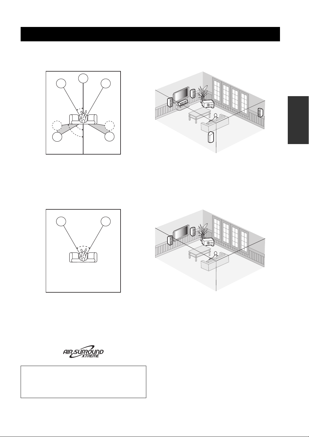
Placing speakers
The speaker layout below shows the speaker setting we recommend.
■ 5.1-channel speaker layout
FL
SL
SL
FL: Front left speaker
FR: Front right speaker
C: Center speaker
SR: Surround right speaker
SL: Surround left speaker
SW: Subwoofer
C
30˚
60˚
80˚
■ 2.1-channel speaker layout
FL
30˚ to 60˚
FR
FL
FR
SW
C
SETUP
SR
SR
SR
SL
FR
FL
FR
SW
FL: Front left speaker
FR: Front right speaker
SW: Subwoofer
You can enjoy 2.1-channel playback using two front
speakers and a subwoofer. Also, you can enjoy surround
playback using the AIR SURROUND XTREME function
of this unit (☞P. 38, 51).
For other speaker combinations
You can enjoy multi-channel sources by using a
speaker combination other than the 5.1-channel or
2.1-channel speaker combinations.
9 En
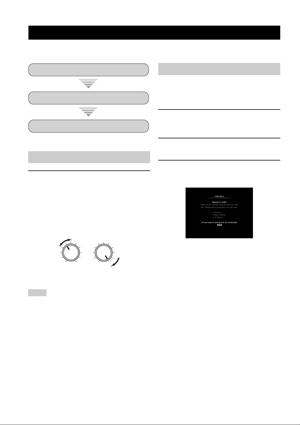
Initial Setup
Once all the connections are finished, optimize this unit for your watching/listening/playing environment by using the
“Initial Setup” menu.
Step 1: Auto Speaker Setup
Step 2: TV Remote Control Setup
Step 3: Source Device Setup
Before starting the Initial Setup
Make sure of the following check points.
❏ Speakers are connected appropriately.
❏ The IR flashers are correctly connected to this
unit and attached to the connected components.
❏ The connected subwoofer is turned on and the
volume level is set to about half way (or slightly
less).
❏ The crossover frequency control of the
connected subwoofer is set to the maximum.
VOLUME
MIN
MAX
Controls of a subwoofer (example)
❏ The room is sufficiently quiet.
CROSSOVER
HIGH CUT
MIN MAX
Step 1: Auto Speaker Setup
Auto Speaker Setup (YPAO) uses unique technology to
optimally calibrate the frequency response and level
according to the speaker configuration, characteristics,
and their distance.
1 Turn on the TV, then set the video input
source selector of the TV to “HDMI 1” (etc.).
Refer to the owner’s manual of the TV for details.
2 Turn on the connected source devices and
subwoofer.
3 Press POWER to turn on this unit.
The “neoHD” logo mark appears, followed by the
“Initial Setup” menu.
y
If the Initial Setup menu does not appear, check the
following check points:
– Is the video input source selector of the TV set correctly?
– Is the TV connected to this unit correctly?
– Is the TV turned on?
– Is this unit connected to the AC wall outlet?
Notes
• Be advised that it is normal for loud test tones to be output
during the Auto Speaker Setup procedure.
• To achieve the best results, make sure the room is as quiet as
possible while the Auto Speaker Setup procedure is in progress.
If there is too much ambient noise, the results may not be
satisfactory.
10 En
4
Select “Yes” to start the initial setup procedure.
TV
POWER
POWER
MENUGUIDE
ENTER
Use these buttons to operate during
EXIT
PREV.
CONTROL BACK
the Initial Setup procedure. ☞ P. 5
The following screen appears:
y
If you select “No”, the Initial Setup procedure will be
skipped. You can perform it in Setup menu later. (☞ P. 37)
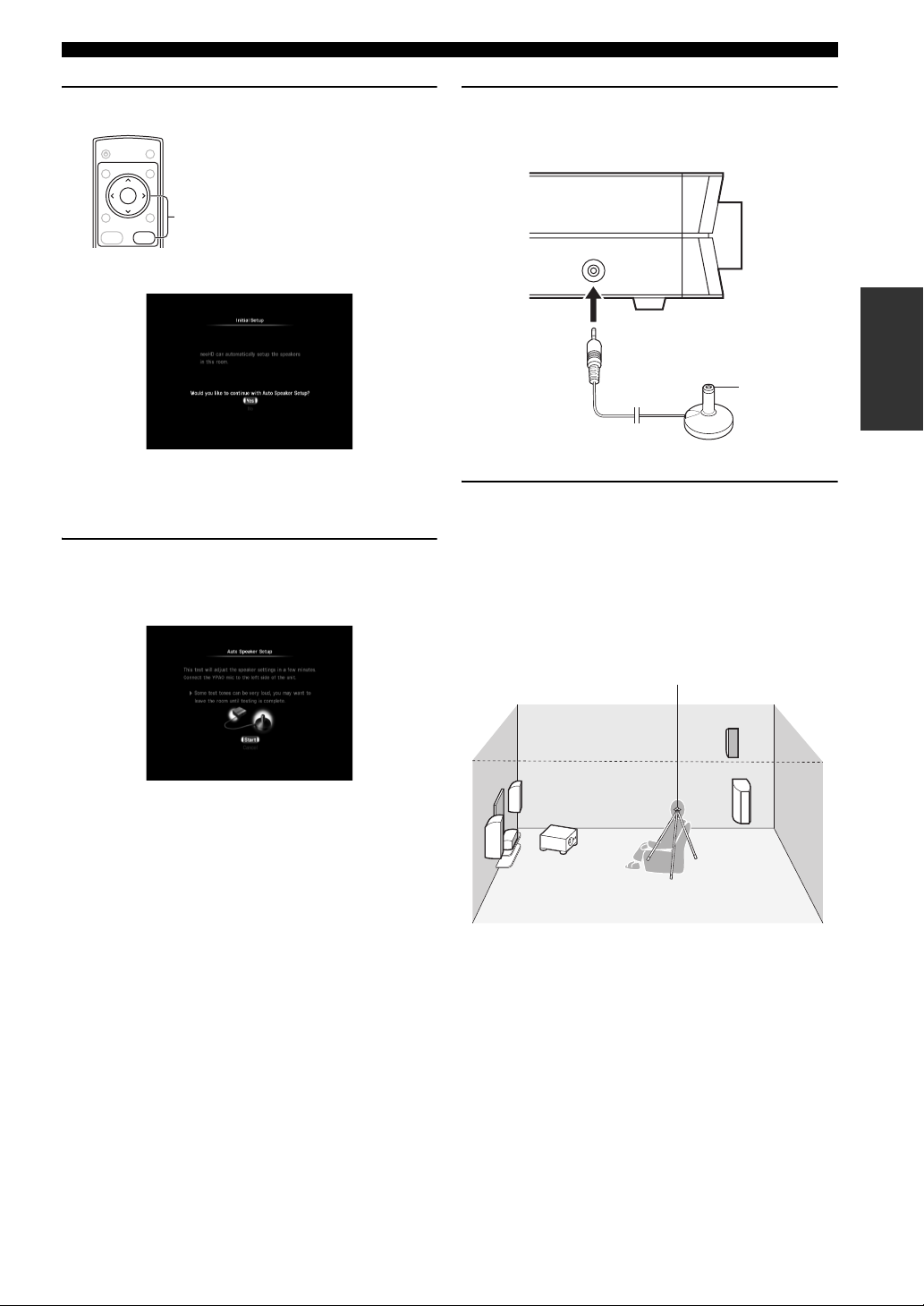
5 Select “Yes” to enter the Auto Speaker Setup
menu.
Read the displayed message carefully.
Initial Setup
6 Connect the supplied YPAO Mic to the YPAO
MIC jack.
(Left side)
YPAO MIC
SETUP
Top
YPAO Mic
7 Place the YPAO Mic at your normal listening
position.
y
It is recommended that you use a tripod, the backrest of the sofa,
etc. to affix the YPAO Mic at the same height as your ears would
be when you are seated in your listening position. You can use the
attached screw of a tripod (etc.) to fix the YPAO Mic to the tripod
(etc.).
If you select “No”, the Auto Speaker Setup procedure
will be skipped. You can perform it later. (☞P. 37)
YPAO Mic
Continued
11 En
Initial Setup
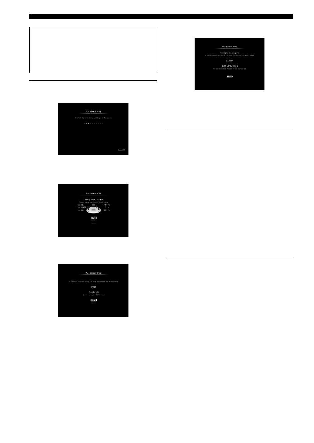
Before proceeding to the next operation
Once you perform the next operation, this unit starts the Auto
Speaker Setup procedure in 10 seconds. During the Auto
Speaker Setup procedure, do not perform any operation on
this unit. For more accurate measurements, we recommend
that you get out of the room or move to a wall away from any
speakers in the meantime. It takes a few minutes.
8 Select “Start” to start the measurement.
This unit starts the count down for the measurement.
Loud test tones are output from each speaker during
the measurement. Once all items are measured, the
following screen appears:
Results (example)
If an error message (☞P. 50) appears
If a warning message (☞ P. 50) appears
Warning message (example)
If the warning message “SWFR LEVEL ERROR”
appears, the adjustments are made, but the adjustment
may not be optimal. Select “Next” to continue the
process.
9 Check the status of each speaker, then select
“Save” to proceed with the Initial Setup
process.
The speaker statuses are as follows:
Yes: Speaker is connected.
No: Speaker is not installed, or speaker cable
is disconnected.
Too Loud: Subwoofer (SWFR) only. The level of
the subwoofer is too high.
Too Low: Subwoofer (SWFR) only. The level of
the subwoofer is too low.
If you are not satisfied with the result, check the
speaker connections and/or subwoofer level, then
select “Retry”.
y
If you want to proceed with the Initial Setup process without
using the result of the measurements, select “Cancel”.
Error message (example)
• Solve the problem (☞ P. 50), then select “Retry” to
retry the measurement.
• Select “Cancel” to cancel the setup process.
12 En
10 Disconnect the YPAO Mic from this unit and
select “OK”.
The YPAO Mic is sensitive to heat. Keep it away
from direct sunlight.
Initial Setup
Step 2: TV Remote Control Setup
By making the TV remote control settings, this unit will
control the power of the TV in accordance with the power
of this unit.
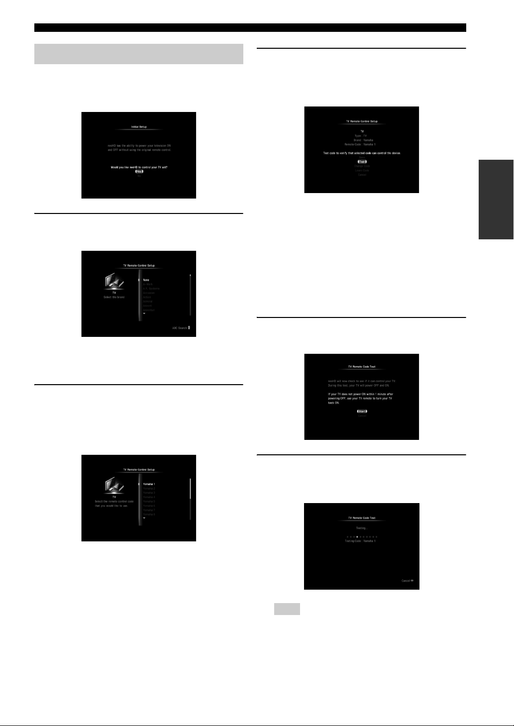
1 Select “Yes” to start the TV Remote Control
Setup procedure.
If you select “No”, the TV Remote Control Setup
procedure will be skipped. You can perform it later.
(☞ P. 42)
3 Select the TV remote control code.
When multiple remote control codes are displayed,
select the first one. Registration confirmation
appears.
SETUP
Save: Confirm the displayed setting.
Tes t: Perform the function test.
Change Code: Select another code.
Learn Code: Jump to the TV Remote Code
Learning screen. (☞ P. 4 2 )
Select this if you want to program
the remote control code manually.
Cancel: Skip the TV remote control
settings. You can set them later.
(☞ P. 42)
4 Check the information, then select “Test”.
The “TV Remote Code Test” screen appears.
2 Select the brand of the TV connected to this
unit.
Press CH u / d to skip through the brand list
alphabetically.
Press PAG E u / d to scroll the list page by page.
5 Read the displayed information, then select
“Start” to start the function test.
The following test screen appears:
Note
This unit tries to turn off/on the TV for test purposes.
Continued
13 En
Initial Setup
pt
15 pt
9 pt
3 pt
3 pt
2 pt
1 pt
Device 1
Cable box
CB-528Time W
15
6 Check whether the TV turned on and off
correctly.
y
• To cancel the TV Remote Code Test procedure, press
BACK.
• If the TV turns off during the test and does not turn back
on after waiting over a minute, turn the TV on using the
TV’s remote control.
7 When the following message appears, select
“Yes” or “No - Try next code”.
Select “Yes” to finish the TV Remote Code Test
procedure or “No - Try next code” to check another
remote control code. When you select “No - Try next
code”, the test mode of the other code starts
immediately.
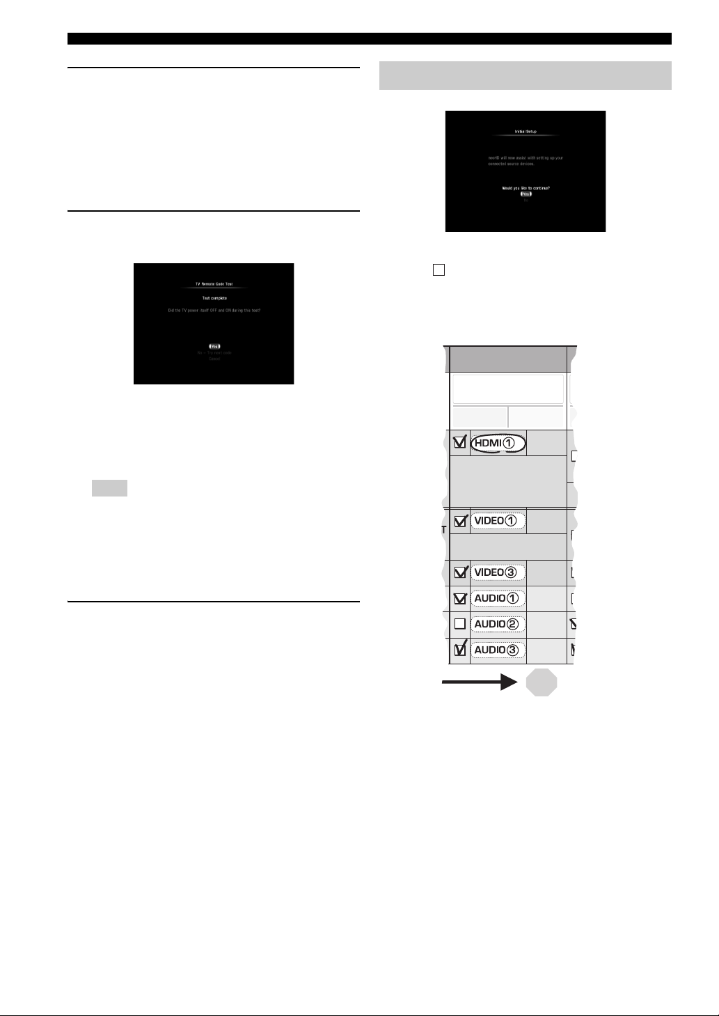
Step 3: Source Device Setup
y
Prepare the Connection Planning Chart of the Quick Setup
Guide in advance.
In these instructions, the examples assume that the
connections below are made.
A
Note
This unit does not contain all possible codes for
commercially available TVs. If this unit does not turn the
TV off/on with the codes provided for that brand, select
“Learn Code” to recall the TV Remote Code Learning
screen (☞ P. 42) and program the remote control code
manually.
8 Select “Save” to finish the TV remote control
code setting and proceed with the Initial
Setup process.
y
When you want to set the TV remote control code again,
select “Change Code”.
14 En
Initial Setup
Device 1
Cable box
CB-528Time W
2 pt
1 pt
pt
15
1 Select “Yes” to start the input source device
setting.
The “Source Device Setup” screen appears.
If you select “No”, the Source Device Setup
procedure will be skipped. You can perform it later.
(☞ P. 39)
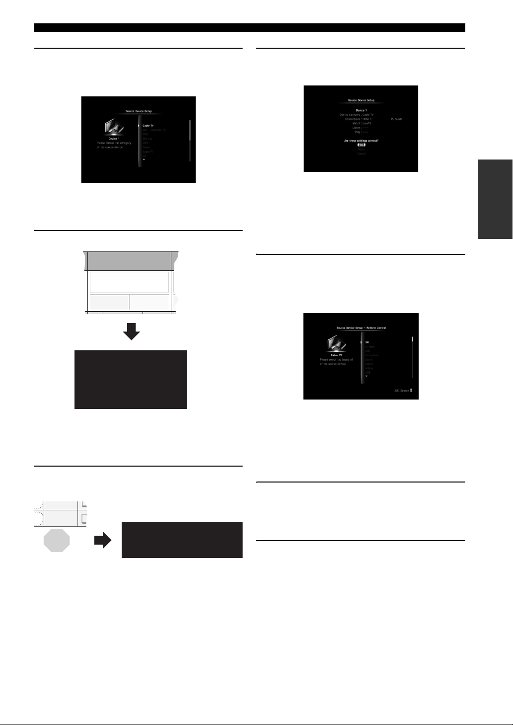
2 Select the type of the device.
4 Check the confirmation screen, then select
“Yes”.
The device type, connection method, and names of
the input displayed in the Watch/Listen/Play source
menu screens (☞P. 18) are shown.
y
When you want to change the setting, select “Retry”.
If you want to discard the setting, select “Cancel”.
5 Select “Yes” to set the remote control code
of the device.
The “Source Device Setup - Remote Control” screen
appears.
SETUP
Cable TV
SAT - Satellite TV
DVD
y
You can change the name of input source displayed in the
source menu screen (☞ P. 18) to the desired one later
(☞ P. 40).
3 Select the terminal to which the source
component is connected.
HDMI 1 15 points
If you select “Game” in step 2, “Will you use this
device to Watch Movies?” appears. Select “Yes” or
“No” in accordance with the intended use.
If you select “DVD”, “Blu-ray”, or “Game” in step 2,
“Will you use this device to Listen to CD’s?” appears.
Select “Yes” or “No” in accordance with the intended
use.
If you select “Other” in step 2, you need to select the
type of the input source device. For example, select
“Cable TV”.
y
You can skip the remote control code settings and set them
later. (☞P. 40 )
6 Select the brand of the device.
Press CH u / d to skip through the brand list
alphabetically.
Press PAG E u / d to scroll the list page by page.
7 Select the remote control code.
When the selected brand has multiple remote control
codes, select the first one.
Continued
15 En
Initial Setup
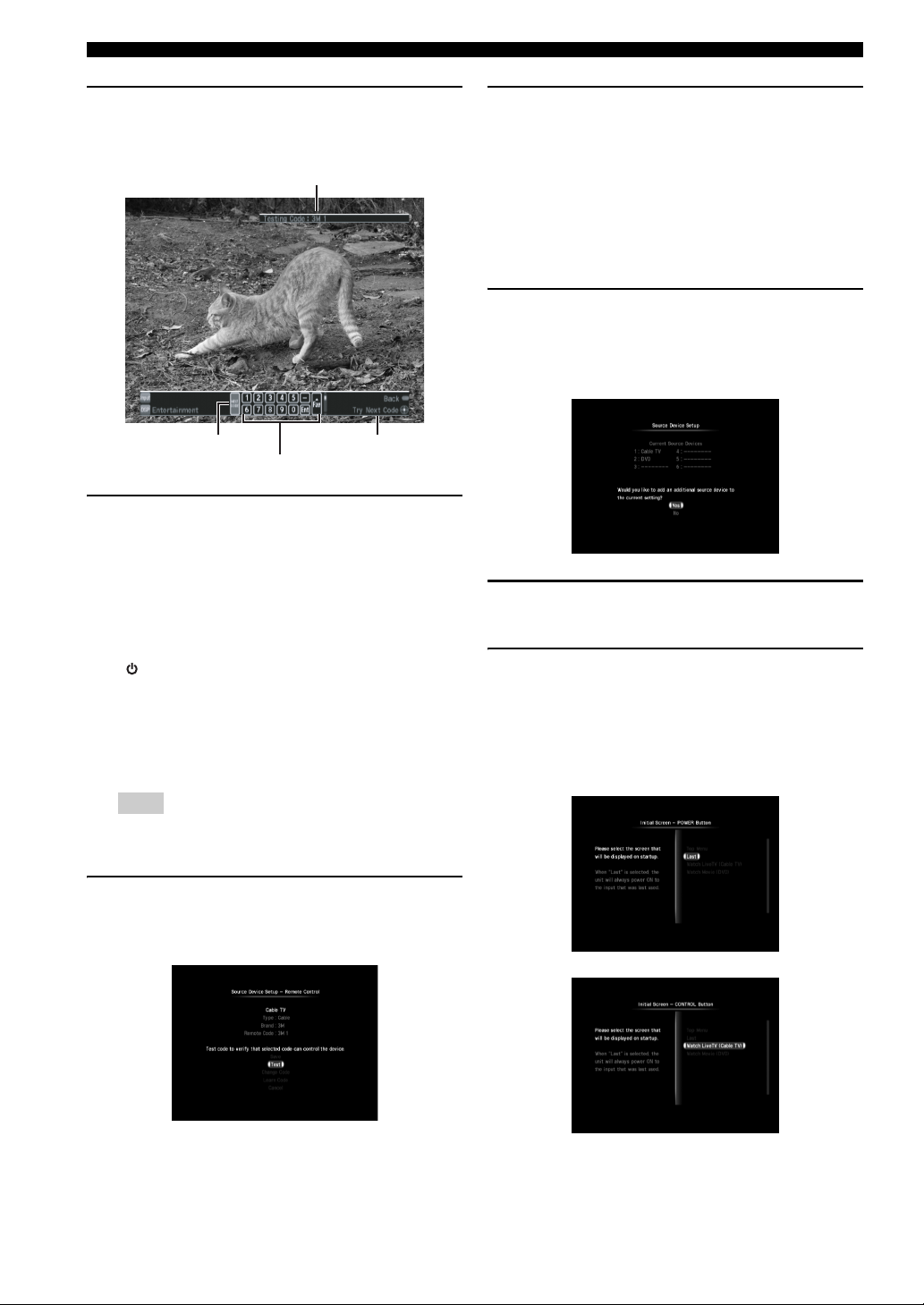
8 Check the confirmation screen, then select
“Test”.
The following test screen appears:
The remote control code being tested
NEXT CODE
Virtual remote control
Function of the
selected button
9 Test some of the controls on the virtual
remote control which is displayed on the
screen to check whether the controls
function correctly.
u / d / j / i: Moves the highlight.
ENTER: Tests the function.
We recommend that you select some buttons besides
“ (Power On/Off)” to test the function.
If controls do not function properly, select “NEXT
CODE” at the left edge of the virtual remote control.
The remote control code switches and you can try the
next remote control code. (Example: from Yamaha1
to Yamaha2)
11 When you find a proper remote control code,
select “Save” to complete the registration.
y
• If you want to discard the setting and make a new setting,
select “Change Code”.
• If this unit does not control the device with any of the
codes provided for the brand, select “Learn Code” to recall
the Remote Code Learning screen (☞ P. 40) and program
the remote control code manually.
12 Select “Yes” to register another input source
device and repeat steps 2 to 11 until all
devices listed in the Quick Start Guide are
set.
13 Select “No” to complete the input source
device registration.
14 Select the first screen to be displayed when
you turn on this unit by pressing POWER or
CONTROL.
For example, you can set this unit to display the cable
box (STB) screen when you turn on this unit by
pressing CONTROL.
Note
If the brand has only one set of remote control codes,
“NEXT CODE” does not function.
10 When you find the remote control code
works (or not), press BACK on the remote
control to return to the confirmation screen.
16 En

15 Select “OK” to complete the Initial Setup
procedure.
Initial Setup
y
You can change the first screen to be displayed later.
(☞ P. 43)
SETUP
17 En
General operation
ge
ge
sc+
s
c
der
g
m
t
(
)
(
)
etc.
y
Select
Setup
]
36
source
]
u
con
menu]
s
]
OL
OL
OL
OL
CK
e
CK
CK
ge
y)
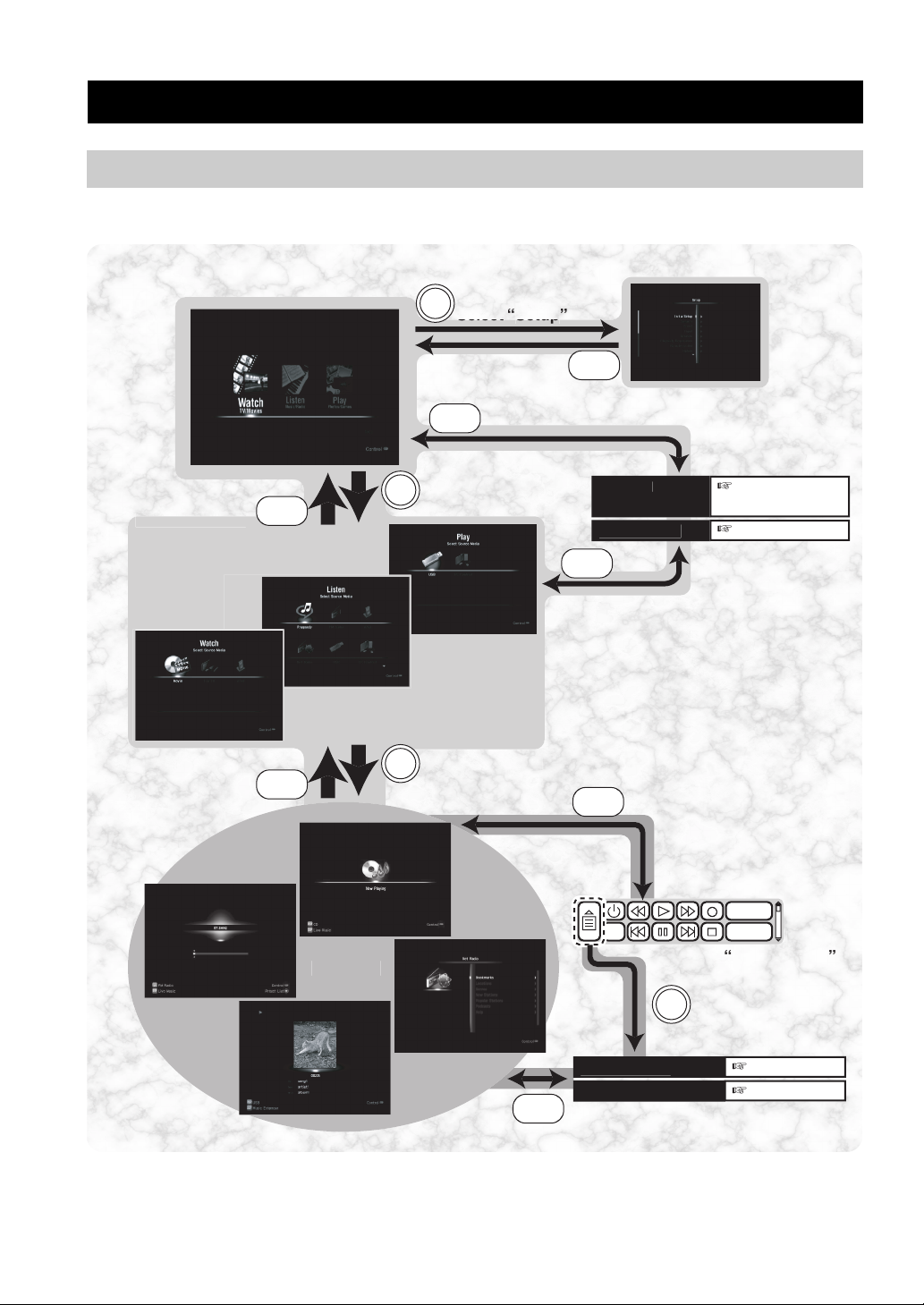
Screens and operation
To control playback and make settings, operate the GUI (graphical user interface) screen displayed on the TV using the
supplied remote control. In most cases, the screen changes as follows.
[Setup menu] ☞ P.
BA
NTR
[Pop up menu
Select an activit
BA
Reor
Now playin
NTR
Next page (Source
menu screen onl
Next pa
Example
Source screen
18 En
BA
Example
elect a sourc
DSP Progra
Audio Adjustmen
NTR
NTR
[Virtual remote control
for external
devices]☞
Di
elect the
Di
Pop up men
Example
i
[Pop up menu
Next pa
Next pa
 Loading...