

Page 1
CONCERT
MARIMBAS
YM-5100A/4900A/4600A/4100A
OWNER’S MANUAL
Make sure to read “PRECAUTIONS FOR HANDLING
GAS SPRING” and “PRECAUTIONS”.
Page 2

PRECAUTIONS
Using the Concert Marimba Safely
The concert marimba is a large and heavy instrument that gets used in various places by persons of all ages,
so please obey the following instructions regarding their regular care and placement.
Especially in the case of children, a responsible adult should provide proper instruction on
how to use and treat the marimba before use.
Preventing Injuries —Make sure that all precautions described below are obeyed—
About
the
Icons
Icons are used in this section to
promote the safe use of this
product, and to prevent you and
others from harm and property
damage. Please fully understand
the meaning of the icons before
reading the manual.
This icon urges you to pay caution (includes dangers and warnings).
This icon indicates actions that are prohibited.
This icon indicates special instructions that should be strictly followed.
For example:
Do not disassemble.
Disregard of the warnings with this mark or misuse may result in
Warning
Before you use the concert marimba, carefully read the instructions listed below and the owner’s manual.
death or personal injury.
Cautions when setting the instrument.
Never place the instrument on an sloping, unstable, etc., platform. The instrument may fall or overturn and result in
injury.
Cautions for treatment of the instrument.
Never lean on or climb onto the instrument. The instrument may fall and result in injury.
Do not play or roughhouse around the instrument. Bumping into the instrument may result in injury.
It may also cause instrument may also fall over. Keep children away from the instrument.
If an earthquake occurs, strong shocks caused by the earthquake may overturn the instrument or cause it to move
about. Stay away from the instrument during earthquakes.
Cautions when moving the instrument.
When moving the instrument on its casters, only move across smooth, flat
surfaces. Hold the instrument by its frame end and push forward slowly.
When moving the instrument on its casters.
1. Avoid moving the instrument across surfaces that are sloped, uneven, or
graveled. The concert marimba can collapse and/or get out of control.
2. Do not run with the instrument. The instrument may become impossible to
stop, crash into a wall, and cause serious injury.
3. If the instrument must be lifted, do so with at least two (2) persons. Lift the
instrument by its frame ends using both hands. Holding the rail section can
result in the instrument dropping or falling off. Never hold the instrument
anywhere other than the frame ends.
Hold the instrument by
the frame end and
push forward slowly.
18
Moving the instrument up or down stairs should never be done with the instrument assembled. Doing so is a danger
as parts can fall off, or you can loose balance causing the instrument to fall over. Only move the instrument after it
has been disassembled.
Page 3
Injury or handicaps to persons caused by the disregard of warnings with
Caution
this mark or, misuse of the instrument, may result in the loss of personal
property.
Please change cracked tone bars as soon as possible. Cracked tone bars have sharp edges that can cut hands.
If the instrument is often moved, bolts, parts, etc., may become loose. After moving the instrument, check and make
sure all bolts, parts, etc., are firmly fastened. Firmly tighten all loose items.
Do not use the hammer for anything other than playing the instrument. It may be the cause of injury or accidents. Do not
let children strike other, etc., with the mallet. Do not allow such dangerous behavior to take place.
When assembling, be careful not to pinch your fingers or hands. Take special care when assembling rails and resonator pipes. Two persons should carry out this part of the assembly, double-checking as the assembly proceeds.
PRECAUTIONS FOR HANDLING GAS SPRING
Please observe the following instructions for proper handling of the gas spring.
1. Precautions for handling the gas spring
This gas spring requires no oil supply to its sliding
section. Additional oil will reduce the sealing durability
and cause the oil to leak.
Never apply any impact to the gas spring. It will cause
oil leakage, malfunction or breakage.
Never disassemble the gas spring. As a high pressure gas is sealed in it, disassembling it will cause a
high risk.
Note that there is not much rigidity in the bending direction. Depending on accuracy in its installation, the
bending load will cause the rod to bend, resulting in
malfunction.
● Do not apply a high tensile load to the gas spring as it will cause damage to the gas spring.
●
In the event of a failure, stop using the instrument and contact the shop of its purchase. If your dealer is
Note that a nick on the piston rod or cylinder will
shorten the service life of the sealing or cause a malfunction.
Do not expose the gas spring to an excessively high
or low temperature. The allowable temperature
range for use is -20°C to 80°C.
Avoid using the instrument where it is exposed to to
rain, water or much dust.
Do not apply an excessive force to lift the frame end
and pull off the gas spring from the leg.
Caution
unable to assist you, please contact Yamaha directly.
2. Instructions for discarding the gas
Make sure to observe the following instructions when discarding the gas spring.
As pressurized nitrogen gas is sealed in the gas spring, be sure to release before discarding it. Or an explosion may occur, causing an injury.
Danger
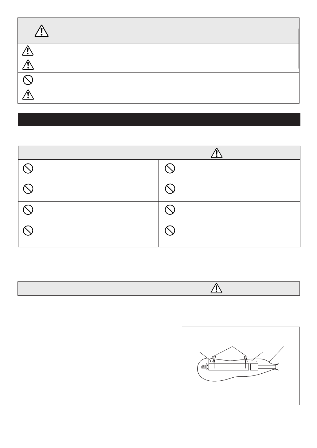
[PRECAUTIONS]
A. Do not crash.
B. Do not cut.
C. Do not make a hole anywhere other than the speci-
fied positions (q and w in the Fig.1).
D. Do not throw it in the fire.
Fig. 1
15mm
Drill
q
w
Plastic bag
35mm
[Discarding procedure]
1. Put the gas spring in a plastic bag. Using a drill of 2 to 3 mm,
make a hole q from outside of the plastic bag at the position
as specified in the figure to release the gas and oil and then
make a hole w at the position as specified. (Be sure to make
holes in the order of q and w. )
2. If a vinyl bag is not used, the oil and drill chips will spread. (In
such a case, wear eye protection glasses. )
* Drill 2 holes as shown above to release
the gas before discarding the gas spring.
19
Page 4
PRECAUTIONS
Please read the following instructions carefully before using your marimbas.
◆ Installation Location
Use or storage in the following locations may cause damage, even when packaged.
• In direct sunlight, such as near a window, or in a closed vehicle in daytime.
• Near heating devices or in other locations subject to excessive heat.
• In excessively cold environment.
• In places with excessive humidity or dust.
• Locations subject to vibrations.
◆ Handling
• Never place an object on or lean against the instrument, as this may cause damage to the tone bars and frame
parts or topple the instrument, which is extremely dangerous.
• Do not use hand orchestra bell mallets or other hard objects on your marimbas. The resulting dents or scratches in
the tone bars could impair the sound.
◆ Moving and Transporting the Instrument
• Before moving the instrument, make sure that the caster brakes are released. Also make sure to lift the instrument
slightly when moving over rough surfaces.
•When the instrument must be transported to a different location, disassemble it to the same state as when it was
purchased (See page 22.), taking care to pack each component properly. Disassembly steps are in the opposite
order of assembly.
◆ When Not in Use
•Always engage the caster brakes.
◆ Maintenance
• The tone bars should be polished from time to time using a soft and dry cloth or silicone cloth. Stains that cannot be
removed with a dry cloth may be wiped off using a small amount of ethyl alcohol. Never use thinner or benzene or
a wet cloth for cleaning purplses.
◆ Keep This Manual for Future Reference
• After reading, make sure to keep the manual in a safe place.
Assembly Cautions
• When assembling/disassembling the instrument, do so with at least two
persons and follow the instructions outlined in this manual. Assembly in
the wrong order can cause the pipes to drop which may result in an
injury, impair the performance functionality of the instrument or cause
noise.
• After final adjustment of the legs the fixing screws must be tightened
securely to prevent loosening. Looseness may cause the instrument to
shift during performance and can also cause noise and other problems.
Retighten the screws from time to time.
20
Page 5

Thank you for purchasing the YAMAHA concert marimbas.
We, at YAMAHA, aiming principally at beautiful sounds and playing
ease, have made strenuous efforts in creating the outstanding instruments and selecting high quality materials, and successfully developed
these marimbas. We are convinced that you will enjoy playing your instrument that produces spreading and yet deep sounds as well as rich
volume to your content.
This manual describes proper use of YAMAHA concert marimbas.
Please read it thoroughly to ensure that your instrument will give you
enjoyment for a long time.
NOMENCLATURE
■ YM-5100A/4900A/4600A/4100A
* The illustration shows model YM-5100A.
Frame end
(Large end)
Leg (Large end)
Resonators (Natural tone side)
Natural tone bars
Resonators (Accidental tone side)
Reinforcement stay
* The YM-5100A is used for illustrative purposes in this
manual. For this reason, the illustrations may not match
with the YM-4900A, YM-4600A, and YM-4100A.
Accidental tone bars
Frame end
(Small end)
Slide guide
Rail
Gas spring
Caster
Slant shaft
Caster
(with brake)
Leg (Small end)
21
Page 6

CONFIRMATION OF PACKING CONTENTS
The shipping carton of your marimba should contain the parts shown below. Before assembling the instrument, confirm that all parts are included as listed.
* In the event that a part is missing, please contact the shop where the instrument was purchased.
q Natural tone bars y Rail (1)
Marking on the end face (A).
u Rail (2)
w Accidental tone bars
e Resonators (Natural tone side)
Resonance Regulator: G
23, A25
(YM-5100A, YM4900A only)
Marking on the end face (B).
B
i Rail (3)
Marking on the end face (C).
C
Rail clamp
Rail clamp
A
r Resonators (Accidental tone side)
Resonance Regulator: F#22, G#24, A#26
(YM-5100A, YM4900A only)
t Reinforcement stay
For large end side
For small end side
o Rail (4)
Marking on the end face (D).
D
YAMAHA logo
!0 Leg (Large end)
!1 Leg (Small end)
22
Page 7

ASSEMBLY
For safety, the instrument should be assembled by at least two persons in a location with sufficient space.
We recommend to you to assemble the instrument on a soft rug or carpet.
z Connect the large and the small end legs using the reinforcement stays.
* Before proceeding to the next step, make sure that the slide guide fixing bolts of the large and small end legs are
securely fastened.
CAUTION
Do not loosen the side guide fixing bolts in this stage. Loosening them will cause
a sudden rise of the frame end which is very dangerous.
Slide guide fixing bolts
1-1. Place the large and small end legs and reinforcement stays so that they will be positioned as illus-
trated below after assembly.
Reinforcement stay (Large end)
Reinforcement stay (Small end)
Leg (Large end)
Slant shaft
Leg (Small end)
23
Page 8

ASSEMBLY
1-2. Connect the reinforcement stays at the center. Align the end of the fixing bolt and the holes in the
reinforcement stays and tighten the fixing bolt securely.
Screw hole
Reinforcement stay
(Large end)
Reinforcement stay
(Small end)
1-3. Install the reinforcement stay to the large end leg.
Insert the “E” marked end of the reinforcement stay (with its slant shaft facing down) into the joint
(marked with “E”) on the large end leg until it stops and tighten the fixing bolt securely.
In the same way, install the reinforcement stay to the small end leg. (There is no marking on the
small end joint.)
Leg (Large end)
Reinforcement stay (Large end)
Fixing bolt
1-4. After making sure that both legs are perpendicular to the floor, fit the end of each slant shaft to the
wing nut located in the lower part of each leg and tighten it securely.
* Make sure that the slant shaft is securely fitted.
Leg (Large end)
Slant shaft
24
Wing nut
Page 9

x Insert the rails (2) and (3) into the end frames of the legs.
2-1. First, insert the rail (2).
A mark “B” is printed on the big end face of the rail (2) and the groove section of the end frame of the
big end leg.
* Do not insert one side of the rail all the way down first, but push both sides into grooves alternately little by
little until both sides are inserted fully and stop.
Next, in the same way, insert the rail (3) securely.
A mark “C” is printed on the big end face of the rail (3) and the groove section of the end frame of the
big end leg.
“C” mark on the rail
and end frame.
Rail clamp
ASSEMBLY
“B” mark on the rail
Rail (3)
and end frame.
Large end
2-2. Engage the short rail clamp located at the center of the rail (3) with the rail (2).
* Release the clamp from its holder, lift and move it to the rail (2) and push it down fully.
Rail (3)
Rail (2)
Small end
Rail (2)
Rail clamp
25
Page 10

ASSEMBLY
c Attach the resonators.
3-1. Unbend the resonators, apply a hook and tighten the wing nut securely.
* All the natural tone resonators are closed at the bottom.
* When assembling the resonators, use care not cause any damage to them.
Hook
Wing nut
3-2. Insert the resonators into the resonator holders on the end frames in the same way as the rails.
* Make sure not to confuse the natural tone resonators and accidental tone resonators.
* Take care not to bump the resonators against the legs, etc.
Resonators (Accidental tone side)
Resonators (Natureal tone side)
26
Page 11

v Insert the rails (1) and (4) into the end frames of the legs.
4-1. Insert the outer rails (1) and (4) in the same way as the inner rails (2) and (3).
A mark “A” is printed on the big end face of the rail (1) and the groove section of the end frame of the
big end leg, and a mark “D” for the rail (4).
“D” mark on the rail
and end frame.
“A” mark on the rail
and end frame.
Large end
ASSEMBLY
Rail (4)
Rail (1)
4-2. Engage the rail clamps on rail (2) and rail (3) with
rail (1) and rail (4) respectively.
YM-5100A Only
4-3. Secure the resonators by fitting their hooks to the
rail clamps engaged in Step 4-2.
* Hooks are provided at 2 locations both on the natu-
ral tone side and the accidental tone side.
* Make sure that each hook is securely fitted.
Small end
Rail clamp
Rail (2)
Rail (1)
Hook
27
Page 12

ASSEMBLY
b Set the tone bars.
5-1. Set the natural tone bars first.
With one person holding the suspension cords on the bass side and the other holding the suspension cords on the treble side securely with both hands, gently place the tone bars on the rails. Align
each tone bar individually and hook its cord onto the corresponding post. After confirming that the
cord is secured to every post, fix the tone bars by pulling the right and left cords forward from the
large end side and hooking the two springs into each other.
* When setting the tone bars, use care not to cause any damage to them.
Small end
Suspension cord
Post
YM-5100A/4900A Only
5-2. Each of F#22, G23, G#24, A25 and A#26 resonators has a resonance regulator. While tapping each tone
bar, move the resonance regulator to find the position where the best resonance is obtained and fix
it there.
* When fixing the resonance regulator, check to ensure that it is not aslant.
Large end
Suspension cord
28
Resonance regulator
Page 13

YM-4600A/4100A Only
5-2. As YM-4600A/4100A does not have a resonance regulator, insert resonators into resonator holders
as shown below.
* The resonators are factory adjusted so that the optimum resonance level is
obtained at 23°C. If desirable resonance is not available due to the
temperature lower or higher than 23°C, adjust setting of the resonators.
Move the resonators to fit into longer grooves when the temperature is higher
and into shorter grooves when the temperature is lower.
Temperature Grooves to use
Higher Short groove
Around 23°C Center groove (“B”)
Lower Long groove (“C”)
(“A” in the figure right)
A : For a higher temperature
B : For a temperature around 23°C
C : For a lower temperature
Resonator
holder
n Adjust the height of the tone bars.
While supporting the frame end of the leg by hand, loosen the fixing bolt of the slide guide on both large
end and small end sides.
Adjust the height to the desired level and tighten the fixing bolts securely.
When adjusting the height, use the lines on the slide guide for reference and make the tone bars in
parallel with the floor surface.
Upon completion of assembly, check to make sure that each bolt is tightened securely.
ASSEMBLY
Fixing bolt
29
Page 14

SPECIFICATIONS/SCALE RANGE
■ YM-5100A
●
Range: C16 – C76 (5 octave)
●
Bars: Honduras Rosewood
●
Bar sizes:
72 – 41 mm (2.8" – 1.6") wide
24 – 20 mm (0.94" – 0.79") thick
●
Resonator: Helmholtz, Elliptic low sound resonator
●
Height Adjustment:
Gas spring system
15 cm (86 – 101 cm)
5.9" (33.9" – 39.8")
●
Dimensions (W x D): 261 x 103 cm (102.8" x 40.6")
●
Weight: 96 kg (211 lbs 10 oz)
■ YM-4900A
●
Range: F21 – C76 (4-1/2 octave)
●
Bars: Honduras Rosewood
●
Bar sizes:
65 – 41 mm (2.5" – 1.6") wide
24 – 20 mm (0.94" – 0.79") thick
●
Resonator: Helmholtz, Elliptic low sound resonator
●
Height Adjustment:
Gas spring system
15 cm (86 – 101 cm)
5.9" (33.9" – 39.8")
●
Dimensions (W x D): 235 x 96 cm (92.5" x 37.8")
●
Weight: 78 kg (171 lbs 15 oz)
■ YM-4600A
●
Range: A25 – C76 (4-1/3 octave)
●
Bars: Honduras Rosewood
●
Bar sizes:
65 – 41 mm (2.5" – 1.6") wide
24 – 20 mm (0.94" – 0.79") thick
●
Resonator: Circle resonator
●
Height Adjustment:
Gas spring system
15 cm (86 – 101 cm)
5.9" (33.9" – 39.8")
●
Dimensions (W x D): 219 x 91 cm (86.2" x 35.8")
●
Weight: 68 kg (149 lbs 14 oz)
■ YM-4100A
●
Range: C28 – C76 (4 octave)
●
Bars: Honduras Rosewood
●
Bar sizes:
65 – 41 mm (2.5" – 1.6") wide
24 – 20 mm (0.94" – 0.79") thick
●
Resonator: Circle resonator
●
Height Adjustment:
Gas spring system
15 cm (83.5 – 98.5 cm)
5.9" (32.9" – 38.8")
●
Dimensions (W x D): 203 x 87 cm (79.9" x 34.3")
●
Weight: 63 kg (138 lbs 14 oz)
● SCALE RANGE
30
YM-4100A
YM-4600A
YM-4900A
YM-5100A
* Specifications subject to change without notice.
 Loading...