

Yamaha YJ50RN Service Manual

YJ50RN
SERVICE MANUAL
LIT-11616-14-50 5LY-28197-E0

EAS00001
©2000 by Yamaha Motor Corporation, U.S.A.
Yamaha Motor Corporation, U.S.A. is expressly
YJ50RN
SERVICE MANUAL
First edition, December, 2000
All rights reserved.
Any reproduction or unauthorized use
without the written permission of
prohibited.
Printed in U.S.A.
P/N LIT-11616-14-50
EAS00002
NOTICE
This manual was produced by the Yamaha Motor Company, Ltd. primarily for use by Yamaha dealers and their qualified mechanics. It is not possible to include all the knowledge of a mechanic in
one manual. Therefore, anyone who uses this book to perform maintenance and repairs on Yamaha
vehicles should have a basic understanding of mechanics and the techniques to repair these types
of vehicles. Repair and maintenance work attempted by anyone without this knowledge is likely to
render the vehicle unsafe and unfit for use.
Yamaha Motor Company, Ltd. is continually striving to improve all of its models. Modifications and
significant changes in specifications or procedures will be forwarded to all authorized Yamaha dealers and will appear in future editions of this manual where applicable.
NOTE:
@
Designs and specifications are subject to change without notice.
EAS00005
IMPORTANT MANUAL INFORMATION
Particularly important information is distinguished in this manual by the following.
The Safety Alert Symbol means ATTENTION! BECOME ALERT! YOUR
SAFETY IS INVOLVED!
WARNING
CAUTION:
NOTE:
Failure to follow WARNING instructions could result in severe injury or death to
the scooter operator, a bystander or a person checking or repairing the scooter.
A CAUTION indicates special precautions that must be taken to avoid damage
to the scooter.
A NOTE provides key information to make procedures easier or clearer.
EAS00007
HOW TO USE THIS MANUAL
This manual is intended as a handy, easy-to-read reference book for the mechanic. Comprehensive
explanations of all installation, removal, disassembly, assembly, repair and check procedures are
laid out with the individual steps in sequential order.
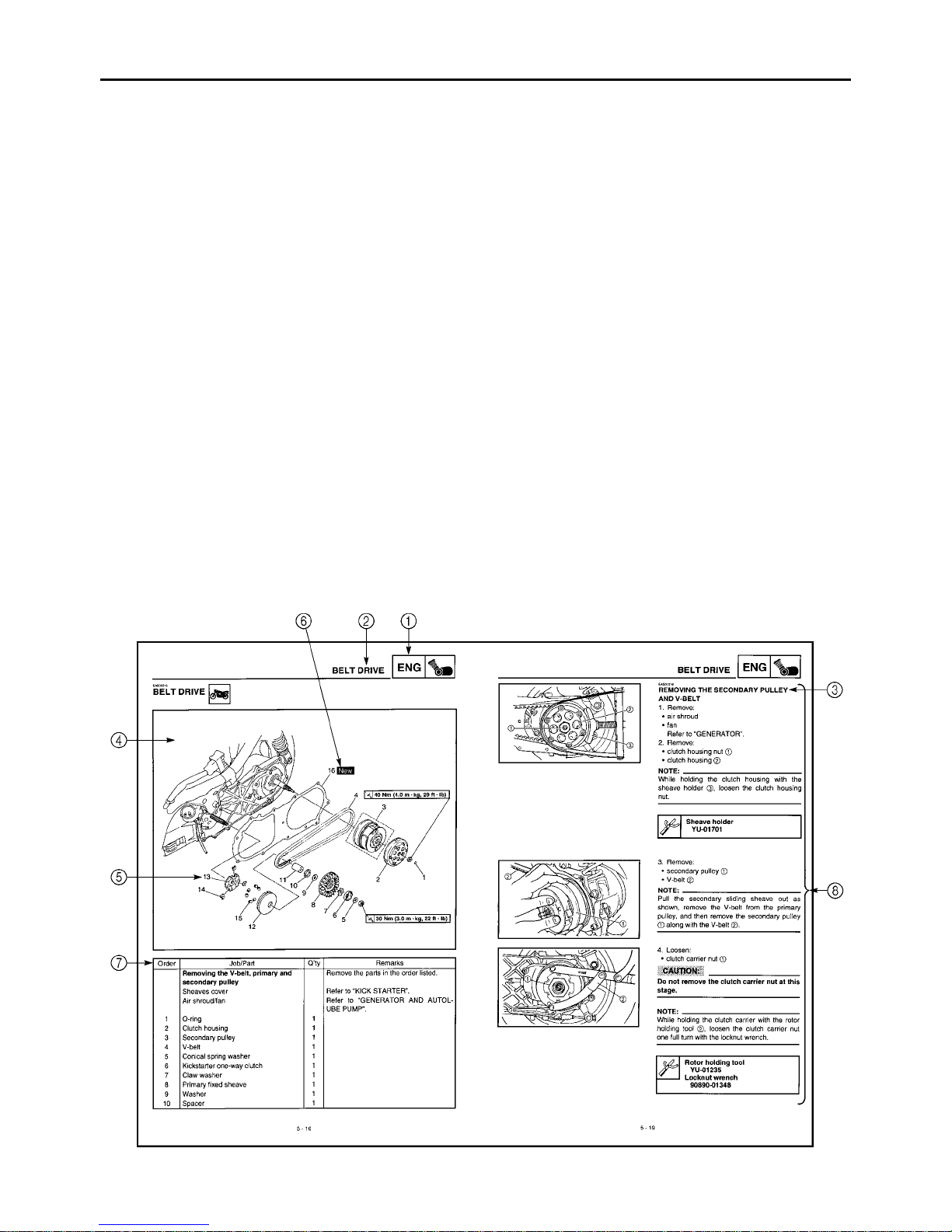
The manual is divided into chapters. An abbreviation and symbol in the upper right corner of each
1
page indicate the current chapter. Refer to “SYMBOLS”.
Each chapter is divided into sections. The current section title is shown at the top of each page,
2
except in Chapter 3 (“PERIODIC CHECKS AND ADJUSTMENTS”), where the sub-sect ion title(s)
appears.
Sub-section titles appear in smaller print than the section title.
3
To help identify parts and clarify procedure steps, there are exploded diagrams at the start of
4
each removal and disassembly section.
Numbers are given in the order of the jobs in the exploded diagram. A circled number indicates a
5
disassembly step.
Symbols indicate parts to be lubricated or replaced. Refer to “SYMBOLS”.
6
A job instruction chart accompanies the exploded diagram, providing the order of jobs, names of
7
parts, notes in jobs, etc.
Jobs requiring more information (such as special tools and technical data) are described sequen-
8
tially.
12
GEN
SPEC
INFO
34
CHK
ENG
ADJ
56
CARB
78
CHAS
EAS00009
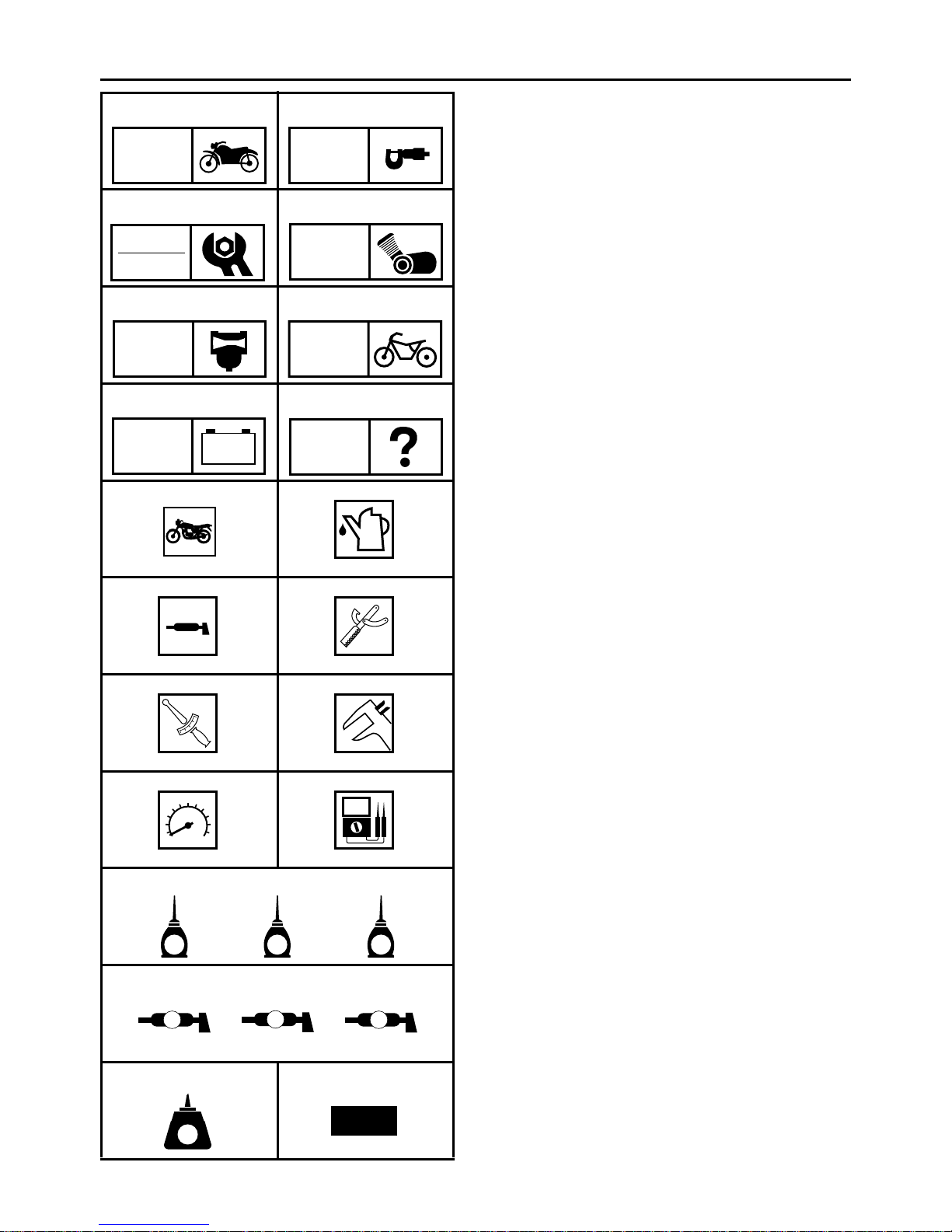
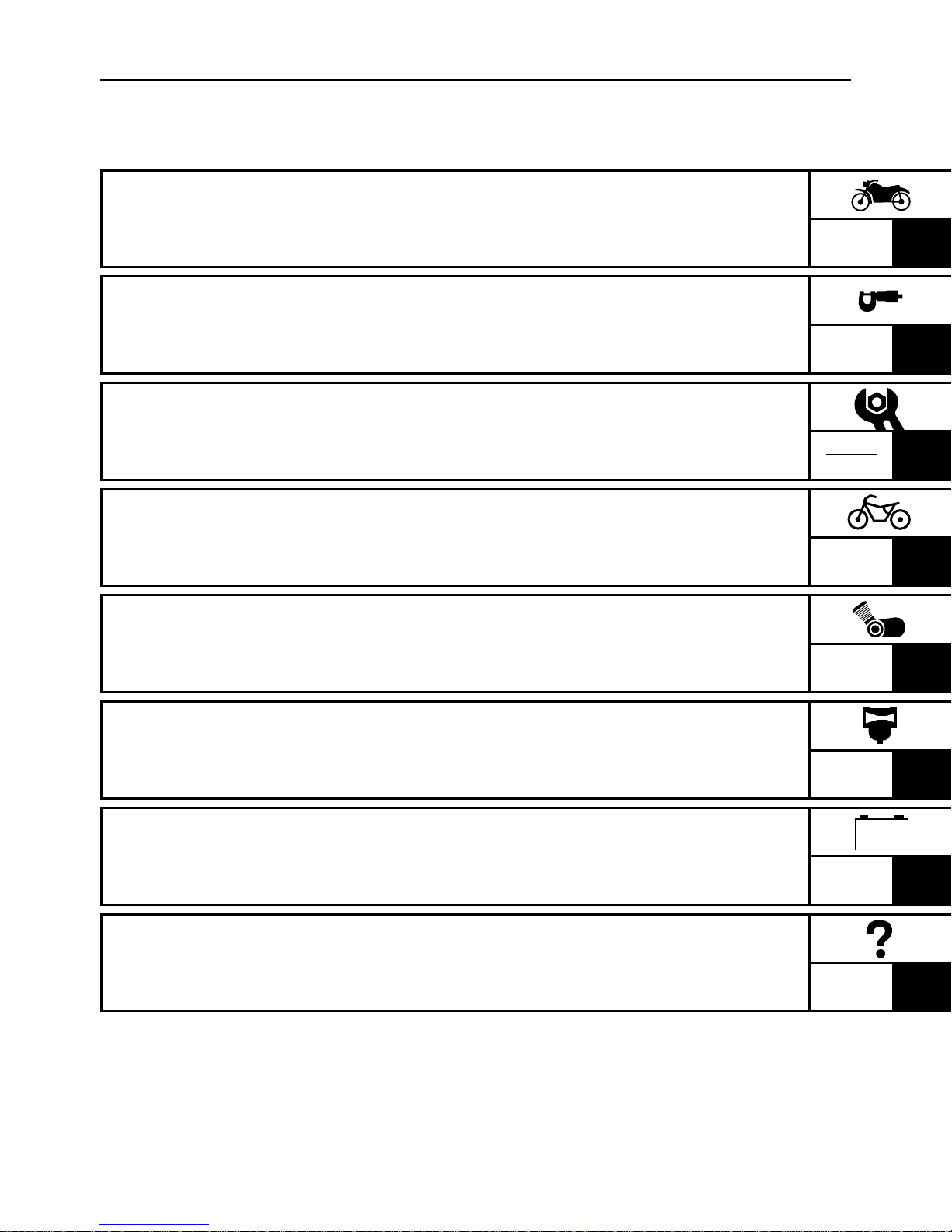
SYMBOLS
The following symbols are not relevant to
every vehicle.
Symbols1 to 8 indicate the subject of each
chapter.
General information
1
Specifications
2
Periodic checks and adjustments
3
Engine
4
Carburetor(s)
5
Chassis
6
Electrical system
7
Troubleshooting
8
–+
TRBL
ELEC
SHTG
90
AB
CD
T
.
R
.
EF
GHI
LS
G
M
M
E
JKL
B
Symbols9 to F indicate the following.
Serviceable with engine mounted
9
Filling fluid
0
Lubricant
A
Special tool
B
Tightening torque
C
Wear limit, clearance
D
Engine speed
E
Electrical data
F
SymbolsG to L in the exploded diagrams
indicate the types of lubricants and lubrication
points.
Engine oil
G
Gear oil
H
Molybdenum disulfide oil
I
Wheel bearing grease
J
Lithium soap base grease
K
Molybdenum disulfide grease
L
MN
LT
New
SymbolsM to N in the exploded diagrams
indicate the following.
®
Apply locking agent (LOCTITE
M
Replace the part
N
)
EAS00011
1
2
3
4
5
6
7
8
TABLE OF CONTENTS
GENERAL INFORMATION
SPECIFICATIONS
PERIODIC CHECKS AND
ADJUSTMENTS
CHASSIS
ENGINE
GEN
INFO
SPEC
CHK
ADJ
CHAS
ENG
CARBURETION
ELECTRICAL SYSTEM
TROUBLESHOOTING
CARB
–+
ELEC
TRBL
SHTG

MEMO

CONTENTS
CHAPTER 1
GENERAL INFORMATION
SCOOTER IDENTIFICATION
VEHICLE IDENTIFICATION NUMBER .....................................................1-1
MODEL CODE...........................................................................................1-1
IMPORTANT INFORMATION
PREPARATION FOR REMOVAL AND DISASSEMBLY...........................1-2
REPLACEMENT PARTS...........................................................................1-2
GASKETS, OIL SEALS AND O-RINGS ....................................................1-2
LOCK WASHERS/PLATES AND COTTER PINS .....................................1-2
BEARINGS AND OIL SEALS....................................................................1-3
CIRCLIPS ..................................................................................................1-3
CHECKING THE CONNECTIONS............................................................1-4
SPECIAL TOOLS
............................................................................................1-5
..........................................................................1-1
..........................................................................1-2
CHAPTER 2
SPECIFICATIONS
GENERAL SPECIFICATIONS
.........................................................................2-1
ENGINE SPECIFICATIONS
CHASSIS SPECIFICATIONS
ELECTRICAL SPECIFICATIONS
CONVERSION TABLE
GENERAL TIGHTENING TORQUE SPECIFICATIONS
TIGHTENING TORQUES
ENGINE TIGHTENING TORQUES.........................................................2-12
CHASSIS TIGHTENING TORQUES.......................................................2-13
LUBRICATION POINTS AND LUBRICANT TYPES
ENGINE...................................................................................................2-14
CHASSIS ................................................................................................2-15
CABLE ROUTING
.........................................................................................2-16
...........................................................................2-2
..........................................................................2-6
...................................................................2-9
..................................................................................2-11
...............................2-11
..............................................................................2-12
.....................................2-14
CHAPTER 3
1
2
3
4
5
6
7
8
PERIODIC CHECKS AND ADJUSTMENTS
INTRODUCTION
PERIODIC MAINTENANCE AND LUBRICATION INTERVALS
SIDE COVERS AND FOOTREST BOARD
FRONT PANEL AND LEG SHIELD
ADJUSTING THE ENGINE IDLING SPEED .............................................3-7
ADJUSTING THE THROTTLE CABLE FREE PLAY.................................3-8
BLEEDING THE AUTOLUBE PUMP.........................................................3-9
CHECKING THE SPARK PLUG..............................................................3-10
MEASURING THE COMPRESSION PRESSURE..................................3-11
CHECKING THE ENGINE OIL LEVEL....................................................3-13
REPLACING THE TRANSMISSION OIL.................................................3-14
CLEANING THE AIR FILTER ELEMENT................................................3-16
CHECKING THE CARBURETOR JOINT................................................3-17
CHECKING THE FUEL AND VACUUM HOSES.....................................3-17
CHECKING THE CRANKCASE BREATHER HOSE...............................3-18
CHECKING THE EXHAUST SYSTEM....................................................3-18
CHASSIS
ADJUSTING THE FRONT BRAKE..........................................................3-19
ADJUSTING THE REAR BRAKE............................................................3-19
CHECKING THE BRAKE SHOES...........................................................3-20
CHECKING AND ADJUSTING THE STEERING HEAD .........................3-20
CHECKING THE FRONT SHOCK ABSORBER .....................................3-22
CHECKING THE TIRES..........................................................................3-22
CHECKING THE WHEELS .....................................................................3-25
CHECKING AND LUBRICATING THE CABLES.....................................3-26
LUBRICATING THE LEVERS .................................................................3-26
LUBRICATING THE CENTERSTAND ....................................................3-26
ELECTRICAL SYSTEM
CHECKING AND CHARGING THE BATTERY.......................................3-27
CHECKING THE FUSE...........................................................................3-34
REPLACING THE HEADLIGHT BULB....................................................3-35
ADJUSTING THE HEADLIGHT BEAM ...................................................3-36
.......................................................................................................3-19
..............................................................................................3-1
....................3-1
.....................................................3-3
................................................................3-5
.................................................................................3-27
GEN
INFO
SPEC
CHK
ADJ
CHAS
ENG
CARB
–+
ELEC
TRBL
SHTG

CHAPTER 4
CHASSIS
FRONT WHEEL AND BRAKE
CHECKING THE FRONT WHEEL ............................................................4-5
CHECKING THE SPEEDOMETER GEAR UNIT.......................................4-6
CHECKING THE BRAKE ..........................................................................4-7
ASSEMBLING THE BRAKE SHOE PLATE ..............................................4-8
INSTALLING THE FRONT WHEEL ..........................................................4-8
REAR WHEEL AND BRAKE
CHECKING THE REAR WHEEL.............................................................4-12
CHECKING THE BRAKE ........................................................................4-12
INSTALLING THE BRAKE SHOE PLATE...............................................4-13
INSTALLING THE BRAKE SHOES.........................................................4-14
INSTALLING THE REAR WHEEL...........................................................4-14
FRONT SHOCK ABSORBER ASSEMBLIES
CHECKING THE FRONT SHOCK ABSORBER ASSEMBLIES..............4-16
INSTALLING THE RELAY ARM..............................................................4-16
HANDLEBAR
REMOVING THE HANDLEBAR..............................................................4-19
CHECKING THE HANDLEBAR...............................................................4-19
INSTALLING THE HANDLEBAR.............................................................4-20
.................................................................................................4-17
........................................................................4-1
.........................................................................4-10
...............................................4-15
STEERING HEAD
REMOVING THE FORK..........................................................................4-24
CHECKING THE STEERING HEAD .......................................................4-24
INSTALLING THE STEERING HEAD .....................................................4-25
REAR SHOCK ABSORBER ASSEMBLY
REMOVING THE REAR SHOCK ABSORBER ASSEMBLY...................4-27
CHECKING THE REAR SHOCK ABSORBER ASSEMBLY....................4-27
INSTALLING THE REAR SHOCK ABSORBER ASSEMBLY..................4-27
..........................................................................................4-22
.....................................................4-26

CHAPTER 5
1
2
3
4
5
6
7
8
ENGINE
ENGINE REMOVAL
INSTALLING THE ENGINE.......................................................................5-3
CYLINDER HEAD, CYLINDER AND PISTON
REMOVING THE CYLINDER AND PISTON.............................................5-6
CHECKING THE CYLINDER HEAD .........................................................5-6
CHECKING THE CYLINDER AND PISTON..............................................5-7
CHECKING THE PISTON RINGS.............................................................5-8
CHECKING THE PISTON PIN ..................................................................5-9
INSTALLING THE PISTON AND CYLINDER .........................................5-11
KICKSTARTER
SHEAVES COVER .................................................................................5-13
CHECKING THE KICKSTARTER ...........................................................5-15
INSTALLING THE KICKSTARTER .........................................................5-15
BELT DRIVE
REMOVING THE SECONDARY PULLEY AND V-BELT ........................5-19
REMOVING THE PRIMARY SHEAVE....................................................5-20
DISASSEMBLING THE SECONDARY PULLEY.....................................5-20
CHECKING THE CLUTCH SHOES ........................................................5-20
CHECKING THE SECONDARY PULLEY............................................... 5-21
CHECKING THE V-BELT........................................................................5-22
CHECKING THE PRIMARY PULLEY WEIGHTS....................................5-22
ASSEMBLING THE SECONDARY PULLEY...........................................5-23
INSTALLING THE PRIMARY PULLEY ...................................................5-24
INSTALLING THE BELT DRIVE..............................................................5-25
.................................................................................................5-16
.........................................................................................5-1
...............................................5-4
..............................................................................................5-13
GEN
INFO
SPEC
CHK
ADJ
CHAS
ENG
CARB
STARTER CLUTCH AND STARTER MOTOR
CHECKING THE STARTER CLUTCH ....................................................5-28
INSTALLING THE STARTER CLUTCH ..................................................5-28
TRANSMISSION
CHECKING THE TRANSMISSION .........................................................5-32
GENERATOR AND AUTOLUBE PUMP
STATOR COIL ASSEMBLY ...................................................................5-33
AUTOLUBE PUMP..................................................................................5-34
REMOVING THE GENERATOR .............................................................5-35
CHECKING THE AUTOLUBE PUMP......................................................5-35
INSTALLING THE AUTOLUBE PUMP....................................................5-35
INSTALLING THE GENERATOR............................................................5-36
...........................................................................................5-30
............................................5-27
.......................................................5-33
–+
ELEC
TRBL
SHTG

CRANKCASE ................................................................................................5-37
DISASSEMBLING THE CRANKCASE....................................................5-39
CHECKING THE CRANKCASE ..............................................................5-39
CHECKING THE BEARINGS AND OIL SEALS......................................5-40
CHECKING THE REED VALVE..............................................................5-40
ASSEMBLING THE CRANKCASE..........................................................5-41
CRANKSHAFT ..............................................................................................5-42
REMOVING THE CRANKSHAFT ASSEMBLY .......................................5-43
CHECKING THE CRANKSHAFT ............................................................5-43
INSTALLING THE CRANKSHAFT ..........................................................5-44
CHAPTER 6
CARBURETION
CARBURETOR................................................................................................6-1
CHECKING THE CARBURETOR .............................................................6-4
ASSEMBLING THE CARBURETOR.........................................................6-5
INSTALLING THE CARBURETOR ...........................................................6-6
MEASURING AND ADJUSTING THE FLOAT HEIGHT............................6-7
CHECKING THE AUTOCHOKE ASSEMBLY ...........................................6-7
CHECKING THE FUEL COCK OPERATION............................................6-8
CHAPTER 7
ELECTRICAL
ELECTRICAL COMPONENTS........................................................................7-1
SWITCHES ......................................................................................................7-2
CHECKING SWITCH CONTINUITY..........................................................7-2
CHECKING THE SWITCHES..........................................................................7-3
CHECKING THE BULBS AND BULB SOCKETS ..........................................7-5
TYPES OF BULBS ....................................................................................7-5
CHECKING THE CONDITION OF THE BULBS........................................7-6
CHECKING THE CONDITION OF THE BULB SOCKETS........................7-7
IGNITION SYSTEM..........................................................................................7-8
CIRCUIT DIAGRAM ..................................................................................7-8
TROUBLESHOOTING...............................................................................7-9
ELECTRIC STARTING SYSTEM ..................................................................7-13
CIRCUIT DIAGRAM ................................................................................7-13
TROUBLESHOOTING.............................................................................7-14
STARTER MOTOR........................................................................................7-17
1
2
3
4
5
6
7
8
CHECKING THE STARTER MOTOR .....................................................7-19
ASSEMBLING THE STARTER MOTOR.................................................7-20
CHARGING SYSTEM....................................................................................7-21
CIRCUIT DIAGRAM ................................................................................7-21
TROUBLESHOOTING.............................................................................7-22
LIGHTING SYSTEM ......................................................................................7-24
CIRCUIT DIAGRAM ................................................................................7-24
TROUBLESHOOTING.............................................................................7-25
CHECKING THE LIGHTING SYSTEM....................................................7-26
SIGNALING SYSTEM....................................................................................7-29
CIRCUIT DIAGRAM ................................................................................7-29
TROUBLESHOOTING.............................................................................7-31
CHECKING THE SIGNALING SYSTEM .................................................7-32
AUTO CHOKE SYSTEM ...............................................................................7-39
CIRCUIT DIAGRAM ................................................................................7-39
TROUBLESHOOTING.............................................................................7-40
GEN
INFO
SPEC
CHK
ADJ
CHAS
CHAPTER 8
TROUBLESHOOTING
STARTING FAILURE/HARD STARTING........................................................8-1
ENGINE.....................................................................................................8-1
FUEL SYSTEM..........................................................................................8-1
ELECTRICAL SYSTEMS ..........................................................................8-1
INCORRECT ENGINE IDLING SPEED...........................................................8-2
ENGINE.....................................................................................................8-2
FUEL SYSTEM..........................................................................................8-2
ELECTRICAL SYSTEMS ..........................................................................8-2
POOR MEDIUM-AND-HIGH-SPEED PERFORMANCE .................................8-2
ENGINE.....................................................................................................8-2
FUEL SYSTEM..........................................................................................8-2
FAULTY CLUTCH ...........................................................................................8-2
ENGINE OPERATES BUT SCOOTER WILL NOT MOVE........................8-2
CLUTCH SLIPS.........................................................................................8-2
POOR STARTING PERFORMANCE........................................................8-2
POOR SPEED PERFORMANCE..............................................................8-2
ENG
CARB
–+
ELEC
TRBL
SHTG

OVERHEATING...............................................................................................8-3
ENGINE.....................................................................................................8-3
FUEL SYSTEM..........................................................................................8-3
CHASSIS...................................................................................................8-3
ELECTRICAL SYSTEMS ..........................................................................8-3
POOR BRAKING PERFORMANCE................................................................8-3
UNSTABLE HANDLING..................................................................................8-3
FAULTY LIGHTING OR SIGNALING SYSTEM..............................................8-4
HEADLIGHT DOES NOT LIGHT...............................................................8-4
HEADLIGHT BULB BURNT OUT..............................................................8-4
TAIL/BRAKE LIGHT DOES NOT LIGHT...................................................8-4
TAIL/BRAKE LIGHT BULB BURNT OUT..................................................8-4
TURN SIGNAL DOES NOT LIGHT ...........................................................8-4
TURN SIGNAL BLINKS SLOWLY.............................................................8-4
TURN SIGNAL REMAINS LIT...................................................................8-4
TURN SIGNAL BLINKS QUICKLY............................................................8-4
HORN DOES NOT SOUND ......................................................................8-4
SCOOTER IDENTIFICATION
1
EAS00015
GENERAL INFORMATION
SCOOTER IDENTIFICATION
1
EAS00017
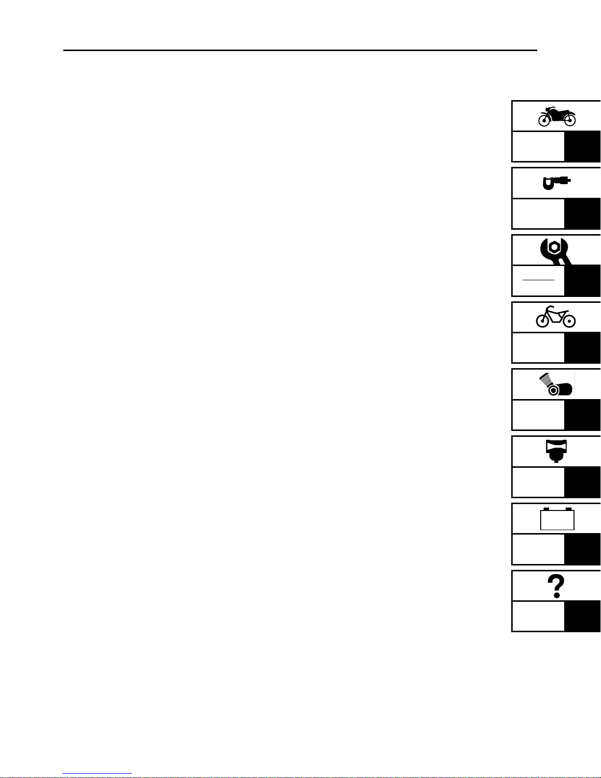
VEHICLE IDENTIFICATION NUMBER
The vehicle identification number 1 is
stamped into the frame.
EAS00018
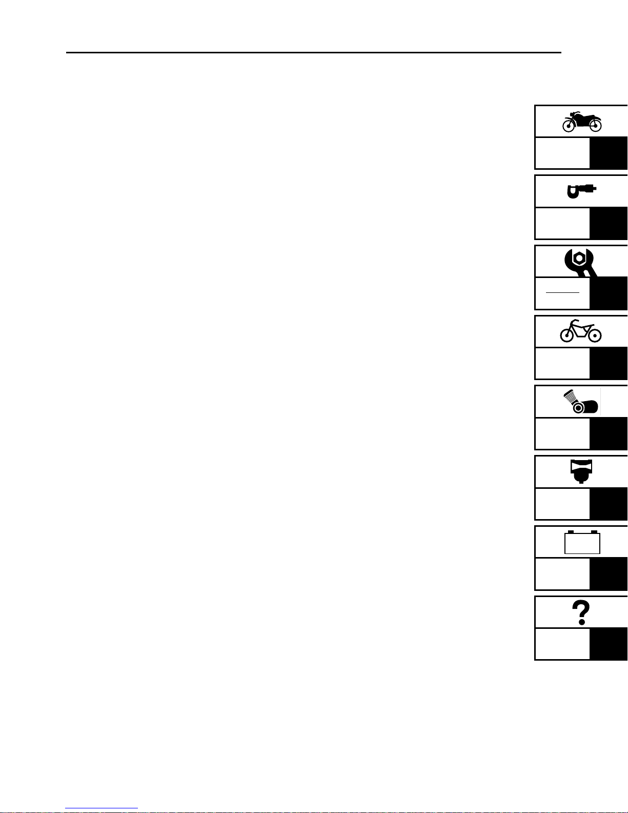
MODEL CODE
The model code label 1 is affixed to the location shown in the figure. Record the information on this label in the space provided. This
information will be needed to order spare
parts.
GEN
INFO
1 - 1
IMPORTANT INFORMATION
EAS00020
IMPORTANT INFORMATION
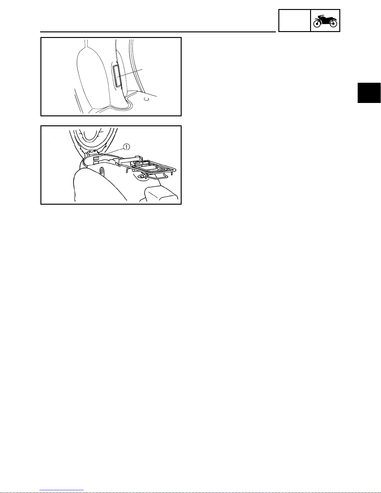
PREPARATION FOR REMOVAL AND
DISASSEMBLY
1. Before removal and disassembly, remove all
dirt, mud, dust and foreign material.
2. Use only the proper tools and cleaning
equipment.
Refer to “SPECIAL TOOLS”.
3. When disassembling, always keep mated
parts together. This includes gears, cylinders, pistons and other parts that have been
“mated” through normal wear. Mated parts
must always be reused or replaced as an
assembly.
4. During disassembly, clean all of the parts
and place them in trays in the order of disassembly. This will speed up assembly and
allow for the correct installation of all parts.
5. Keep all parts away from any source of fire.
EAS00021
REPLACEMENT PARTS
Use only genuine Yamaha parts for all
replacements. Use oil and grease recommended by Yamaha for all lubrication jobs.
Other brands may be similar in function and
appearance, but inferior in quality.
GEN
INFO
EAS00022
GASKETS, OIL SEALS AND O-RINGS
1. When overhauling the engine, replace all
gaskets, seals and O-rings. All gasket surfaces, oil seal lips and O-rings must be
cleaned.
2. During reassembly, properly oil all mating
parts and bearings and lubricate the oil seal
lips with grease.
EAS00023
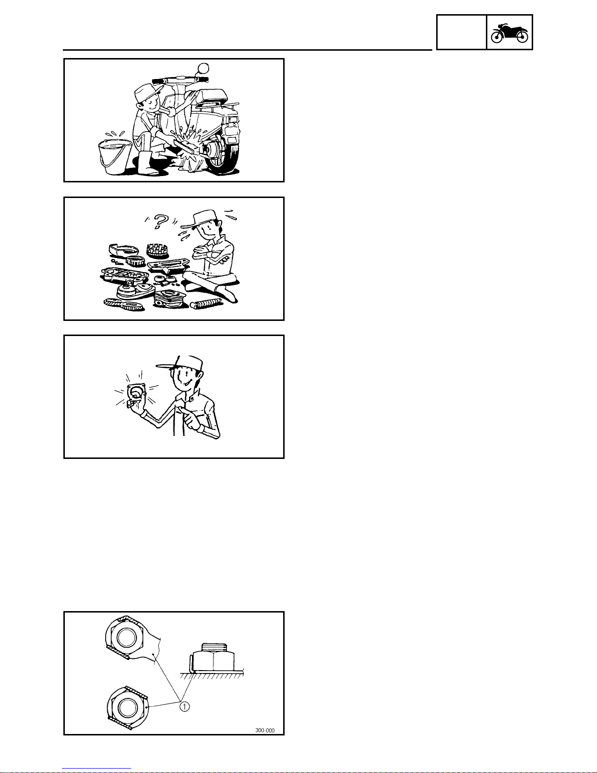
LOCK WASHERS/PLATES AND COTTER
PINS
After removal, replace all lock washers/plates
1
and cotter pins. After the bolt or nut has
been tightened to specification, bend the lock
tabs along a flat of the bolt or nut.
1 - 2
IMPORTANT INFORMATION
1
EAS00024
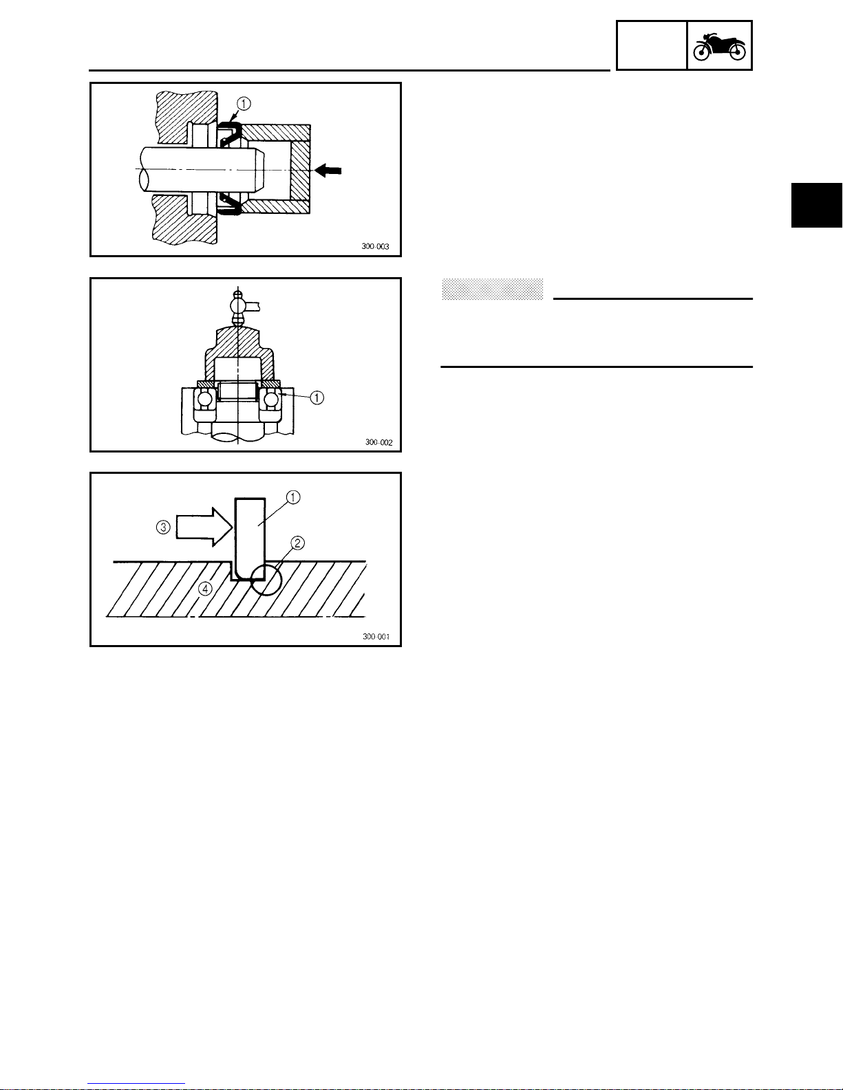
BEARINGS AND OIL SEALS
Install bearings and oil seals so that the manufacturer’s marks or numbers are visible. When
installing oil seals, lubricate the oil seal lips
with a light coat of lithium soap base grease.
Oil bearings liberally when installing, if appropriate.
Oil seal
1
CAUTION:
@
Do not spin the bearing with compressed
air because this will damage the bearing
surfaces.
Bearing
1
GEN
INFO
EAS00025
CIRCLIPS
Before reassembly, check all circlips carefully
and replace damaged or distorted circlips.
Always replace piston pin clips after one use.
When installing a circlip 1, make sure the
sharp-edged corner 2 is positioned opposite
the thrust 3 that the circlip receives.
Shaft
4
1 - 3
IMPORTANT INFORMATION
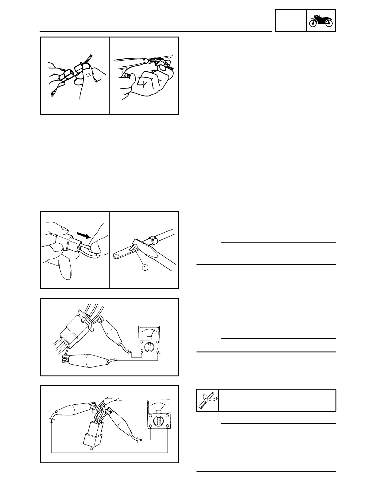
EAS00026
CHECKING THE CONNECTIONS
Check the leads, couplers, and connectors for
stains, rust, moisture, etc.
1. Disconnect:
• lead
• coupler
• connector
2. Check:
• lead
• coupler
• connector
Moisture → Dry with an air blower.
Rust/stains→ Connect and disconnect several times.
GEN
INFO
3. Check:
• all connections
Loose connection → Connect properly.
NOTE:
@
If the pin 1 on the terminal is flattened, bend it
up.
4. Connect:
• lead
• coupler
• connector
NOTE:
@
Make sure all connections are tight.
5. Check:
• continuity
(with the pocket tester)
Pocket tester
YU-03112
NOTE:
@
• If there is no continuity, clean the terminals.
• When checking the wire harness, perform
steps (1) to (3).
• As a quick remedy, use a contact revitalizer
available at most part stores.
1 - 4
GEN
1
SPECIAL TOOLS
EAS00027
SPECIAL TOOLS
The following special tools are necessary for complete and accurate tune-up and assembly. Use
only the appropriate special tools as this will help prevent damage caused by the use of inappropriate tools or improvised techniques. Special tools, part numbers or both may differ depending on the
country.
When placing an order, refer to the list provided below to avoid any mistakes.
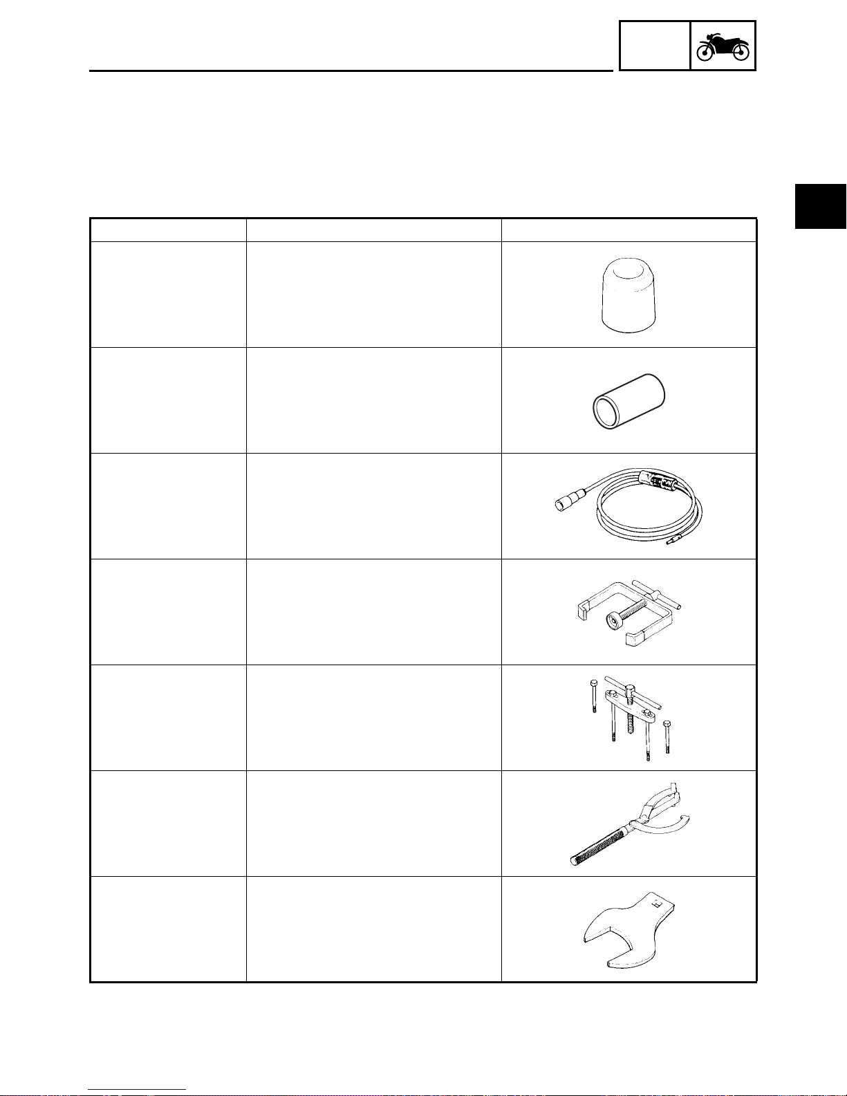
Tool No. Tool name/Function Illustration
Oil seal guide
YM-01409
This tool is used to install oil seals.
Crankshaft installer spacer
YM-01411
This tool is used to install the crankshaft.
Dynamic spark tester
INFO
YM-34487
YS-28891
YU-01135
YU-01235
This tool is used to check the ignition
system components.
Clutch spring holder
This tool is used to disassembly and
assembly the secondary pulley.
Crankcase separating tool
This tool is used to remove the crankshaft and to separate the crankcase.
Rotor holding tool
This tool is used to hold the generator
rotor when removing or installing the
generator rotor bolt.
Steering nut wrench (45 mm)
YU-01444
This tool is used to loosen and tighten
the lower steering stem nut.
1 - 5
GEN
SPECIAL TOOLS
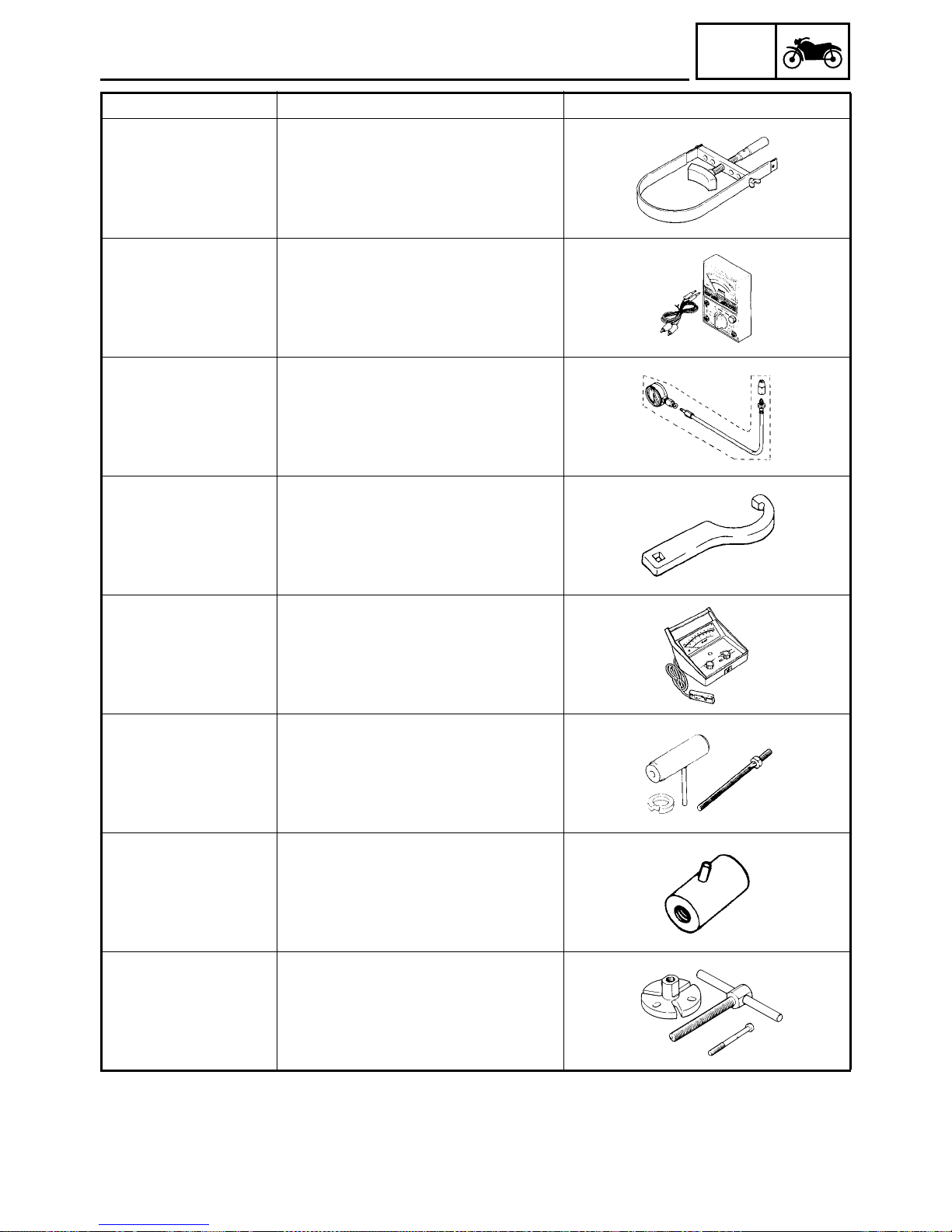
Tool No. Tool name/Function Illustration
Sheave holder
INFO
YU-01701
YU-03112
YU-33223
YU-33975
This tool is used to hold the clutch housing when removing or installing the
clutch housing nut.
Pocket tester
This tool is used to check the electrical
system.
Compression gauge
This tool is used to measure engine
compression.
Steering nut wrench
This tool is used to loosen or tighten the
steering stem ring nut.
Inductive tachometer
YU-8036-A
Crankshaft installer tool
set
YU-90050
Crankshaft installer pot
YU-90058
Crankshaft installer bolt
YU-90060
YU-90062
YU-90105
This tool is used to check engine speed.
Crankshaft installer tool set
Crankshaft installer pot
Crankshaft installer bolt
These tools are used to install the
crankshaft.
Crankshaft installer adaptor (M10)
This tool is used to install the crankshaft.
Flywheel puller set
This tool is used to remove the generator rotor.
1 - 6
GEN
1
SPECIAL TOOLS
Tool No. Tool name/Function Illustration
Quick Gasket
®
INFO
ACC-1100-15-01
This sealant is used to seal to mating
surfaces (e.g., crankcase mating surfaces).
1 - 7
GENERAL SPECIFICATIONS
SPEC
SPECIFICATIONS
GENERAL SPECIFICATIONS
Item Standard Limit
Model code
Dimensions
Overall length 1,630 mm (64.1 in) ---Overall width 630 mm (24.8 in) ---Overall height 1,030 mm (40.5 in) ---Seat height 715 mm (28.1 in) ---Wheelbase 1,150 mm (45.3 in) ---Minimum ground clearance 85 mm (3.3 in) ---Minimum turning radius 1,600 mm (63 in) ----
Weight
Wet (with oil and a full fuel tank) 74 kg (163 lb) ----
5LY1 ----
2 - 1
ENGINE SPECIFICATIONS
2
SPEC
ENGINE SPECIFICATIONS
Item Standard Limit
Engine
Engine type Air-cooled, 2-stroke ---Induction system Reed valve ---Displacement 49 cm
Cylinder arrangement Forward inclined single cylinder ---Bore× stroke 40.0 × 39.2 mm (1.57 × 1.54 in) ---Compression ratio 7.3 : 1 ---Engine idling speed 1,800 r/min ----
Fuel
Recommended fuel Unleaded fuel ---Fuel tank capacity
Total (including reserve) 6 L (5.3 Imp qt, 6.3 US qt) ----
Engine oil
Lubrication system Separate lubrication (Yamaha autolube) ---Oil type or grade Yamalube 2-cycle oil or
Quantity
Capacity 1.4 L (1.23 Imp qt, 1.48 US qt) ---Air filter oil grade Foam air-filter oil or SAE 10W30SE ----
Transmission
Recommended oil Yamalube 4 (10W30) or SAE 10W30 type
Periodic oil change 0.1 L (0.09 Imp qt, 0.11 US qt) ----
Total amount 0.11 L (0.1 Imp qt, 0.12 US qt) ----
Starting system type
Spark plug
Model (manufacturer) × quantity BPR7HS (NGK) ---Spark plug gap 0.6 ~ 0.7 mm (0.02 ~ 0.03 in) ----
Cylinder head
Max. warpage ---- 0.02 mm
Cylinder
Cylinder arrangement Forward inclined single cylinder ---Bore× stroke 40.0 × 39.2 mm (1.57 × 1.54 in) ---Compression ratio 7.3 : 1 ---Bore 39.993 ~ 40.012 mm (1.5745 ~ 1.5753 in) ---Max. taper ---- 0.05 mm
Max. out-of-round ---- 0. 05 mm
3
----
2-stroke engine oil
SE motor oil
Electric and kick starter ----
(0.0008 in)
(0.002 in)
(0.002 in)
----
----
----
2 - 2
ENGINE SPECIFICATIONS
SPEC
Item Standard Limit
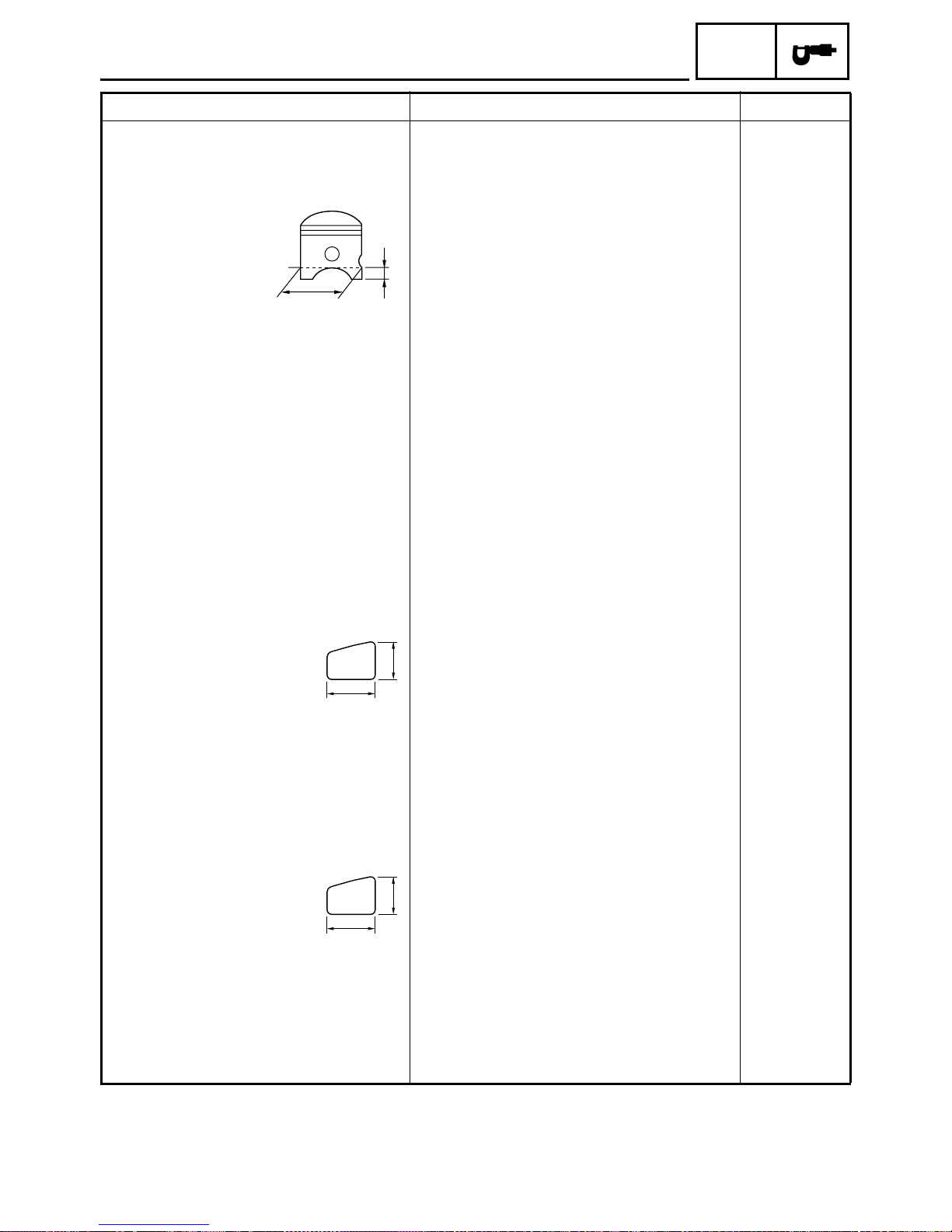
Piston
Piston-to-cylinder clearance 0.03 ~ 0.05 mm (0.0012 ~ 0.0020 in) 0.10 mm
(0.0039 in)
Diameter D 39.952 ~ 39.969 mm (1.5729 ~ 1.5736 in) ----
H
D
Height H 5 mm (0.2 in) ---Oversize 1st ---- ---Oversize 2nd ---- ---Piston pin bore (in the piston)
Diameter 10.004 ~ 10.015 mm (0.3939 ~ 0.3943 in) 10.045 mm
(0.3955 in)
Offset 0 mm (0 in) ----
Piston pin
Outside diameter 9.996 ~ 10.000 mm (0.3935 ~ 0.3937 in) 9.976 mm
(0.3928 in)
Piston-pin-to-piston-pin-bore clearance
0.004 ~ 0.019 mm (0.00016 ~ 0.00075 in) 0.069 mm
(0.0027 in)
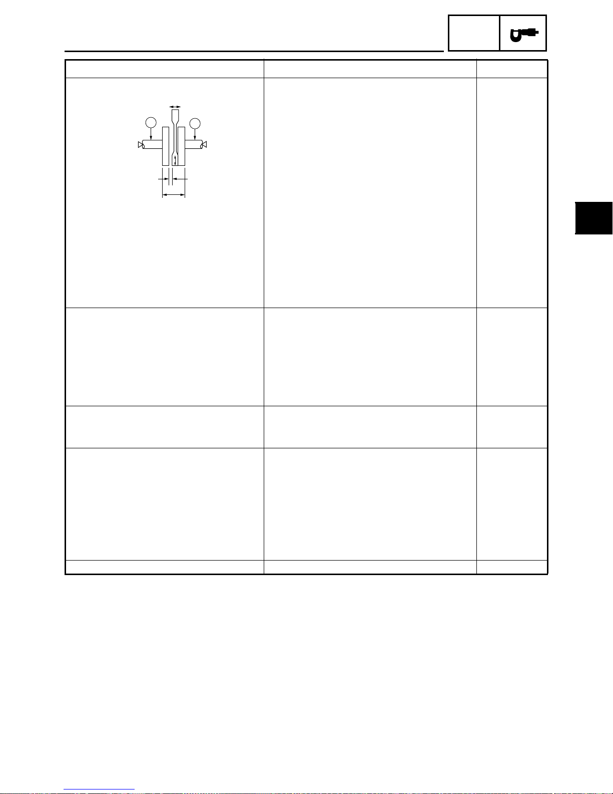
Piston ring
Top ring
B
T
Ring type Keystone ---Dimensions (B × T) 1.2 × 1.8 mm (0.05 × 0.07 in) ---End gap (installed) 0.15 ~ 0.35 mm (0.006 ~ 0.014 in) 0.70 mm
(0.028 in)
Ring side clearance 0.03 ~ 0.05 mm (0.0012 ~ 0.0020 in) 0.10 mm
(0.0039 in)
2nd ring
B
T
Ring type Keystone ---Dimensions (B × T) 1.2 × 1.8 mm (0.05 × 0.07 in) ---End gap (installed) 0.15 ~ 0.35 mm (0.006 ~ 0.014 in) 0.70 mm
(0.028 in)
Ring side clearance 0.03 ~ 0.05 mm (0.0012 ~ 0.0020 in) 0.10 mm
(0.0039 in)
2 - 3
Crankshaft
2
ENGINE SPECIFICATIONS
Item Standard Limit
F
SPEC
C
Width A 37.90 ~ 37.95 mm (1.492 ~ 1.494 in) ---Max. runout C ---- 0.03 mm
Big end side clearance D 0.35 ~ 0.75 mm (0.0138 ~ 0.0295 in) 1.0 mm
Big end radial clearance E 0.004 ~ 0.017 mm (0.00016 ~ 0.00067 in) ---Small end free play F 0.4 ~ 0.8 mm (0.02 ~ 0.03 in) ----
Clutch
Clutch type Dry, centrifugal automatic ---Clutch shoe
Thickness 4.0 mm (0.157 in) 1.0 mm
Clutch shoe spring
Free length 29.9 mm (1.18 in) ----
Kickstarter
Kickstarter type Ratchet ---Kickstarter pinion gear clip force 0.15 ~ 0.25 kg (0.34 ~ 0.56 lb) ----
Transmission
Transmission type V-belt automatic ---Primary reduction system Helical ---Primary reduction ratio 48/13 (3.692) ---Secondary reduction system Spur gear ---Secondary reduction ratio 42/13 (3.231) ---Operation Centrifugal automatic type ---Single speed automatic 2.183 ~ 1.050:1 ----
Air filter type
C
E
D
A
(0.0012 in)
(0.0394 in)
(0.039 in)
Wet element ----
2 - 4
ENGINE SPECIFICATIONS
Item Standard Limit
Carburetor
Model (manufacturer) × quantity Y14P/1 (TEIKEI) × 1 ---Throttle cable free play
(at the flange of the throttle grip)
ID mark 5LY1 00 ---Main jet #64 ---Main air jet 2.0 ---Jet needle 3SOC-3/5 ---Needle jet 2.090 ---Cutaway 2.5 ---Pilot jet #46 ---Bypass 1 0.8 ---Valve seat size 1.8 ---Starter jet 1 #46 ---Float height 15 ~ 17 mm (0.59 ~ 0.67 in) ----
Reed valve
Thickness 0.164 ~ 0.176 mm (0.0065 ~ 0.0069 in) ---Valve stopper height 7.0 ~ 7.4 mm (0.28 ~ 0.29 in) ---Valve bending limit 0.2 mm (0.008 in) ----
Autolube pump
Plunger diameter 2.62 mm (0.103 in) ---Minimum stroke 0.1 mm (0.0039 in) ---Maximum stroke 0.49 mm (0.0193 in) ----
1.5 ~ 3.5 mm (0.06 ~ 0.14 in) ----
SPEC
2 - 5
CHASSIS SPECIFICATIONS
2
SPEC
CHASSIS SPECIFICATIONS
Item Standard Limit
Frame
Frame type Steel tube underbone ---Caster angle 25° ---Trail 71 mm (2.8 in) ----
Front wheel
Wheel type Panel wheel ---Rim
Size 10 × 2.15 ----
Material Steel ---Wheel travel 60 mm (2.36 in) ---Wheel runout
Max. radial wheel runout ---- 1.0 mm
(0.04 in)
Max. lateral wheel runout ---- 1.0 mm
(0.04 in)
Rear wheel
Wheel type Panel wheel ---Rim
Size 10 × 2.15 ----
Material Steel ---Wheel travel 46 mm (1.81 in) ---Wheel runout
Max. radial wheel runout ---- 1.0 mm
(0.04 in)
Max. lateral wheel runout ---- 1.0 mm
(0.04 in)
Front tire
Tire type Tubeless ---Size 80/90-10 (34J) ---Model (manufacturer) MB38/C-922 (INOUE/CHENG SHIN) ---Tire pressure (cold)
0 ~ 90 kg (0 ~ 198 lb) 150 kPa (1.50 kg/cm
Min. tire tread depth ---- 1.0 mm
Rear tire
Tire type Tubeless ---Size 80/90-10 (34J) ---Model (manufacturer) MB3 8 / C - 9 2 2 ( I N O U E /C H E N G S H I N ) ---Tire pressure (cold)
0 ~ 90 kg (0 ~ 198 lb) 175 kPa (1.75 kg/cm
Min. tire tread depth ---- 1.0 mm
2
, 21.8 psi) ----
(0.04 in)
2
, 25.4 psi) ----
(0.04 in)
2 - 6

CHASSIS SPECIFICATIONS
Item Standard Limit
Front brake
Brake type Drum brake ---Operation Right-hand operation ---Brake lever free play (at lever end) 10 ~ 20 mm (0.39 ~ 0.79 in) ---Dram brake type Leading, trailing ----
Brake drum inside diameter 110 mm (4.33 in) 110.5 mm
Lining thickness 4 mm (0.16 in) 2 mm
Rear brake
Brake type Drum brake ---Operation Left-hand operation ---Brake lever free play (at lever end) 10 ~ 20 mm (0.39 ~ 0.79 in) ---Drum brake type Leading, trailing ----
Brake drum inside diameter 110 mm (4.33 in) 110.5 mm
Lining thickness 4 mm (0.16 in) 2 mm
Front suspension
Suspension type Bottom link fork ---Front fork type Coil spring/oil damper ---Front fork travel 40 mm (1.57 in) ---Spring
Free length 156.5 mm (6.16 in) 153.4 mm
Spring rate (K1) 12.8 N/mm (1.28 kgf/mm, 73.09 lb/in) ----
Spring stroke (K1) 0 ~ 20 mm (0 ~ 0.79 in) ----
Spring rate (K2) 30.4 N/mm (3.04 kgf/mm, 173.58 lb/in) ----
Spring stroke (K2) 20 ~ 30 mm (0.79 ~ 1.18 in) ----
Spring rate (K3) 67.6 N/mm (6.76 kgf/mm, 386 lb/in) ----
Spring stroke (K3) 30 ~ 40 mm (1.18 ~ 1.57 in) ---Optional spring available No ----
Steering
Steering bearing type Ball and race bearing ----
SPEC
(4.35 in)
(0.08 in)
(4.35 in)
(0.08 in)
(6.04 in)
2 - 7
CHASSIS SPECIFICATIONS
2
Item Standard Limit
Rear suspension
Suspension type Unit swing ---Rear shock absorber assembly type Coil spring/oil damper ---Rear shock absorber assembly travel 45 mm (1.77 in) ---Spring
Free length 173.5 mm (6.83 in) 170.0 mm
Installed length 166.5 mm (6.56 in) ----
Spring rate (K1) 34.5 N/mm (3.45 kgf/mm, 197 lb/in) ----
Spring stroke (K1) 0 ~ 45 mm (0 ~ 1.77 in) ---Optional spring available No ----
SPEC
(6.69 in)
2 - 8
ELECTRICAL SPECIFICATIONS
SPEC
ELECTRICAL SPECIFICATIONS
Item Standard Limit
System voltage
Ignition system
Ignition system type DC.CDI ---Ignition timing 14° BTDC at 5,000 r/min ---Advancer type Fixed ---Pickup coil resistance/color 248 ~ 372 Ω/W/L–W/R ---CDI unit model (manufacturer) 5BM (YAMAHA) ----
Ignition coil
Model (manufacturer) 2JN (YAMAHA) ---Minimum ignition spark gap 6 mm (0.24 in) ---Primary coil resistance 0.18 ~ 0.28 Ω ---Secondary coil resistance 6.32 ~ 9.48 kΩ ----
Spark plug cap
Material Resin ---Resistance 5 kΩ ----
Charging system
System type AC magneto ---Model (manufacturer) F5BM (YAMAHA) ---Standard output 14 V/120 W at 5,000 r/min ---Stator coil resistance (W-B) 0.29 ~ 0.43 Ω ----
Voltage regulator
Regulator type Semiconductor, short circuit ---Model (manufacturer) SH671-12 (SHINDENGEN) ---No-load regulated voltage (DC) 14.0 ~ 15.0 V ---No-load regulated voltage (AC) 12.3 ~ 13.3 V ----
Rectifier
Model (manufacturer) SH671-12 (SHINDENGEN) ---Rectifier capacity (DC) 8 A ---Rectifier capacity (AC) 12 A ---Withstand voltage 200 V ----
Battery
Battery type GT4B-5 ---Battery voltage/capacity 12 V/2.5 AH ---Specific gravity 1.350 ----
Headlight type
Indicator light type × quantity
Bulbs (voltage/wattage × quantity)
Headlight 12 V 35 W/35 W × 1 ---Tail/brake light 12 V 27 W/8 W × 1 ---Front turn signal light 12 V 10 W × 2 ---Rear turn signal light 12 V 10 W × 2 ---Meter light 12 V 1.7 W × 1 ---Fuel level indicator light 14 V 1.4 W × 1 ---High beam indicator light 12 V 1.7 W × 1 ---Oil level indicator light 12 V 1.7 W × 1 ---Turn indicator light 14 V 3 W × 1 ----
12 V ----
Halogen bulb ---Bulb type × 3 ----
2 - 9
 Loading...