

Yamaha YFM350R-W Supplementary Service Manual

YFM350R-W
N0A1-AE1
SUPPLEMENTARY
SERVICE MANUAL

FOREWORD
This Supplementary Service Manual has been prepared to introduce new service and data for the
YFM350R-W. For complete service information procedures it is necessary to use this Supplementary Service Manual together with the following manual.
YFM350X(J) ’97 SERVICE MANUAL: 3GD-AE5
YFM350X(P) 2002 SUPPLEMENTARY SERVICE MANUAL: 3GD-AE6
YFM350S SUPPLEMENTARY SERVICE MANUAL: 3GD-AE7
YFM350R-W
SUPPLEMENTARY
SERVICE MANUAL
©2005 by MBK Industrie
First edition, April 2005
All rights reserved.
Any reproduction or unauthorized use
without the written permission of
MBK Industrie
is expressly prohibited.

EBS00002
NOTICE
This manual was produced by MBK industrie primarily for use by Yamaha dealers and their qualified
mechanics. It is not possible to include all the knowledge of a mechanic in one manual, so it is
assumed that anyone who uses this book to perform maintenance and repairs on Yamaha machine
has a basic understanding of the mechanical ideas and the procedures of machine repair. Repairs
attempted by anyone without this knowledge are likely to render the machine unsafe and unfit for
use.
Yamaha Motor Company, Ltd. is continually striving to improve all its models. Modifications and significant changes in specifications or procedures will be forwarded to all authorized Yamaha dealers
and will appear in future editions of this manual where applicable.
NOTE:
_
Designs and specifications are subject to change without notice.
EBS00003
IMPORTANT INFORMATION
Particularly important information is distinguished in this manual by the following notations.
The Safety Alert Symbol means ATTENTION! BECOME ALERT! YOUR
SAFETY IS INVOLVED!
WARNING
CAUTION:
NOTE:
Failure to follow WARNING instructions could result in severe injury or death
to the machine operator, a bystander or a person checking or repairing the
machine.
A CAUTION indicates special precautions that must be taken to avoid damage to the machine.
A NOTE provides key information to make procedures easier or clearer.
EBS00004
HOW TO USE THIS MANUAL
MANUAL ORGANIZATION
This manual consists of chapters for the main categories of subjects. (See “symbols”)
1st title 1: This is the title of the chapter with its symbol in the upper right corner of each page.
2nd title 2: This title indicates the section of the chapter and only appears on the first page of each
section. It is located in the upper left corner of the page.
3rd title 3: This title indicates a sub-section that is followed by step-by-step procedures accompanied by corresponding illustrations.
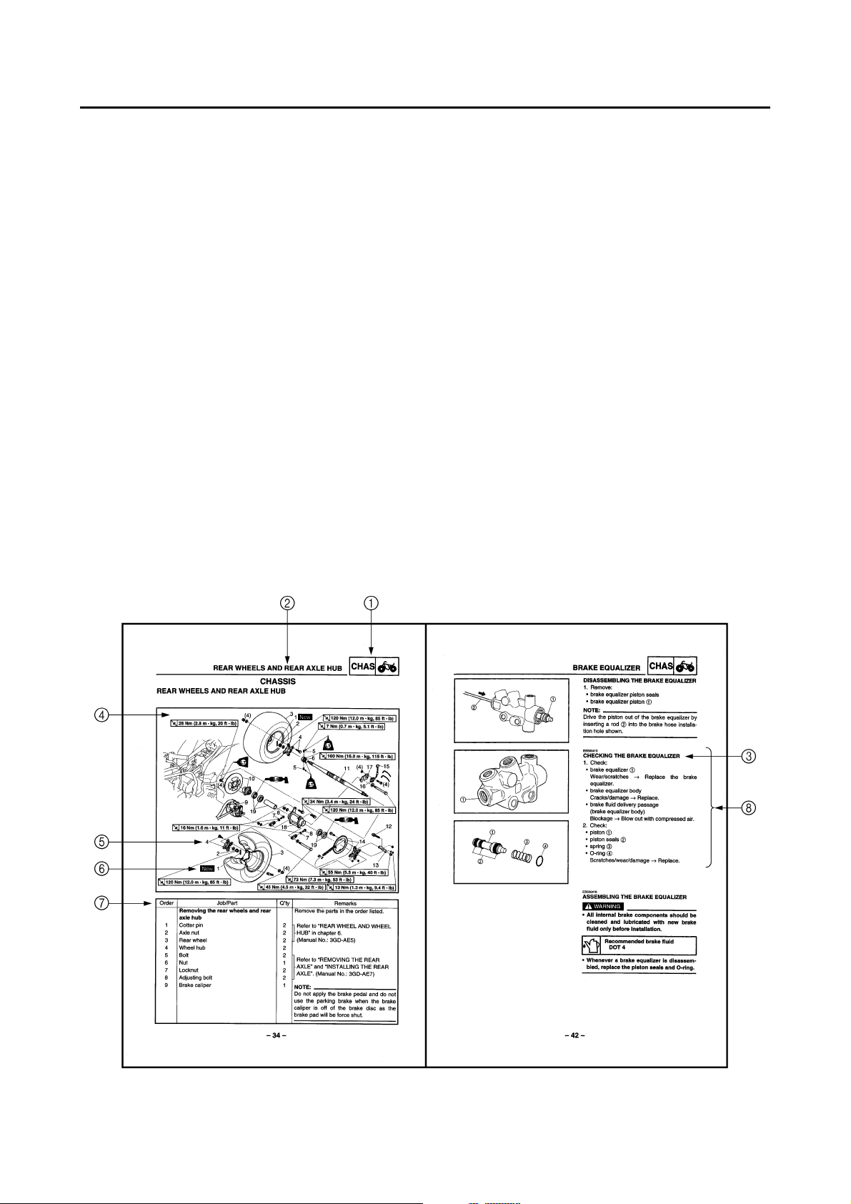
EXPLODED DIAGRAMS
To help identify parts and clarify procedure steps, there are exploded diagrams at the start of each
removal and disassembly section.
1. An easy-to-see exploded diagram 4 is provided for removal and disassembly jobs.
2. Numbers 5 are given in the order of the jobs in the exploded diagram. A number that is enclosed
by a circle indicates a disassembly step.
3. An explanation of jobs and notes is presented in an easy-to-read way by the use of symbol marks
6
. The meanings of the symbol marks are given on the next page.
4. A job instruction chart 7 accompanies the exploded diagram, providing the order of jobs, names
of parts, notes in jobs, etc.
5. For jobs requiring more information, the step-by-step format supplements 8 are given in addition
to the exploded diagram and the job instruction chart.
12
GEN
INFO
34
SPEC
CHK
ADJ
56
CARB
78
ENG
CHAS
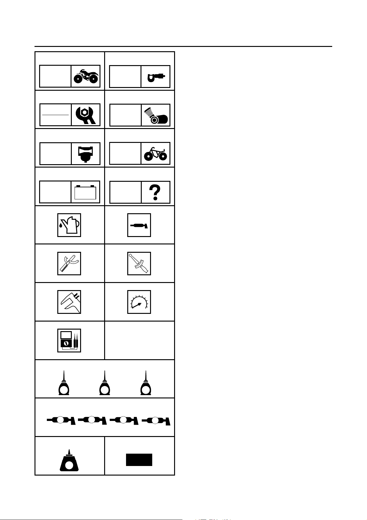
EB003000
ILLUSTRATED SYMBOLS
Illustrated symbols 1 to 8 are printed on the
top right of each page and indicate the subject
of each chapter.
General information
1
Specifications
2
Periodic checks and adjustments
3
Engine
4
Carburetion
5
Chassis
6
Electrical
7
Troubleshooting
8
– +
TRBL
ELEC
SHTG
90
AB
T
.
R
.
CD
E
FGH
Illustrated symbols 9 to E are used to identify
the specifications appearing in the text.
Filling fluid
9
Lubricant
0
Special tool
A
Torque
B
Wear limit, clearance
C
Engine speed
D
, V, A
Ω
E
Illustrated symbols F to L in the exploded
diagrams indicate the types of lubricants and
lubrication points.
LS
G
M
M
S
New
E
I
MN
JKL
B
LT
Apply engine oil
F
Apply gear oil
G
Apply molybdenum disulfide oil
H
Apply wheel bearing grease
I
Apply lightweight lithium soap base grease
J
Apply molybdenum disulfide grease
K
Apply silicon grease
L
Illustrated symbols M to N in the exploded
diagrams indicate where to apply a locking
agent M and when to install a new part N.
Apply the locking agent (LOCTITE
M
Replace
N
®
)

CONTENTS
GENERAL INFORMATION
MACHINE IDENTIFICATION ....................................................................... 1
VEHICLE IDENTIFICATION NUMBER.................................................. 1
SPECIFICATIONS
GENERAL SPECIFICATIONS .....................................................................2
MAINTENANCE SPECIFICATIONS ............................................................ 3
ENGINE .................................................................................................3
CHASSIS ...............................................................................................4
ELECTRICAL.........................................................................................5
CABLE ROUTING ........................................................................................6
PERIODIC CHECKS AND ADJUSTMENTS
INTRODUCTION ........................................................................................ 20
PERIODIC MAINTENANCE/LUBRICATION..............................................20
SEAT, FENDERS AND FUEL TANK.......................................................... 22
HEADLIGHTS AND FRONT FENDER ................................................ 22
REAR FENDER ................................................................................... 24
LICENSE PLATE LIGHT AND REAR TURN SIGNAL LIGHTS ........... 26
CHASSIS.................................................................................................... 27
BLEEDING THE HYDRAULIC BRAKE SYSTEM ................................ 27
ADJUSTING THE DRIVE CHAIN SLACK............................................ 29
ELECTRICAL ............................................................................................. 31
ADJUSTING THE HEADLIGHT BEAM................................................31
REPLACING THE HEADLIGHT BULB ................................................ 31
..............................................................................................2
................................................................................1
.................................................... 20
CHASSIS
REAR WHEELS AND REAR AXLE HUB ................................................... 34
REAR BRAKE ............................................................................................ 37
BRAKE EQUALIZER .................................................................................. 40
STEERING SYSTEM ................................................................................. 45
..........................................................................................................34
INSTALLING THE SPEED SENSOR................................................... 36
REAR BRAKE MASTER CYLINDER...................................................37
INSTALLING THE REAR BRAKE MASTER CYLINDER..................... 39
BRAKE EQUALIZER............................................................................ 40
DISASSEMBLING THE BRAKE EQUALIZER ..................................... 42
CHECKING THE BRAKE EQUALIZER ...............................................42
ASSEMBLING THE BRAKE EQUALIZER........................................... 42
INSTALLING THE BRAKE EQUALIZER .............................................43
HANDLEBAR ....................................................................................... 45
INSTALLING THE LEFT REARVIEW MIRROR BRACKETS
AND CLUTCH LEVER ........................................................................ 47
INSTALLING THE METER ASSEMBLY.............................................. 47
STEERING STEM................................................................................ 48
INSTALLING THE STEERING LOCK STOPPER................................ 50

ELECTRICAL ................................................................................................... 51
ELECTRICAL COMPONENTS................................................................... 51
LIGHTING SYSTEM................................................................................... 53
CIRCUIT DIAGRAM............................................................................. 53
CHECKING THE LIGHTING SYSTEM ................................................ 54
SIGNALING SYSTEM ................................................................................ 57
CIRCUIT DIAGRAM............................................................................. 57
CHECKING THE SIGNALING SYSTEM.............................................. 59
YFM350R-W 2006 WIRING DIAGRAM
1
MACHINE IDENTIFICATION
EBS00009
GENERAL INFORMATION
MACHINE IDENTIFICATION
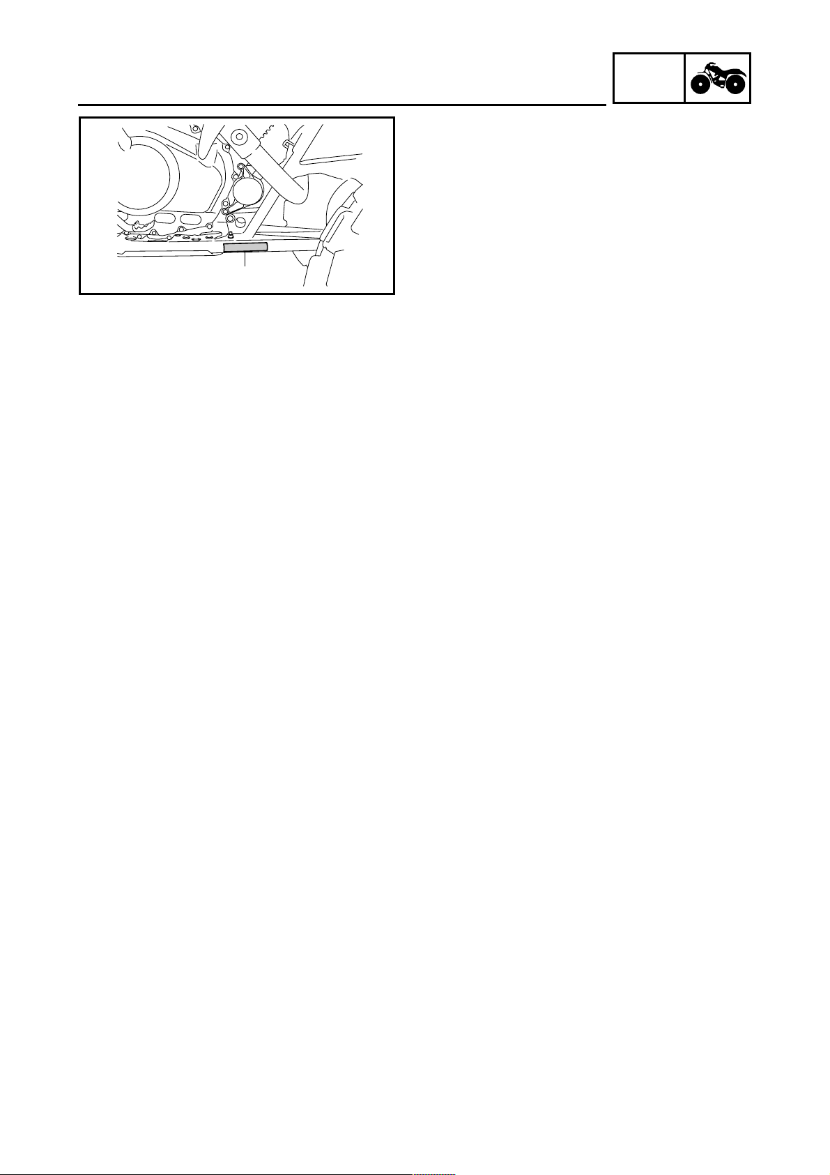
EBS00010
VEHICLE IDENTIFICATION NUMBER
The vehicle identification number 1 is
stamped into the right side of the frame.
GEN
INFO
– 1 –
GENERAL SPECIFICATIONS
SPECIFICATIONS
GENERAL SPECIFICATIONS
Model YFM350R-W
SPEC
Model code number
Basic weight
With oil and full fuel tank 184.0 kg (406 lb)
Tires
Type Tubeless
Size front AT21 × 7-10 24J
rear AT20 × 10-9 34J
Manufacturer front MAXXIS
rear MAXXIS
Type front C9207
rear M976
Brakes
Front brake type Dual disc brake
operation Right hand operation
Rear brake type Dual disc brake (front) and single disc brake
system Front and rear unified
operation Right foot operation
Headlight type
Bulb wattage × quantity
Headlight 12 V 35 W/35 W × 1
Auxiliary light 12 V 5 W × 1
Tail/brake light 12 V 5 W/21 W × 1
License plate light 12 V 5 W × 1
Front turn signal light 12 V 10 W × 2
Rear turn signal light 12 V 10 W × 2
Meter lighting EL (electro-luminescent lighting)
Neutral indicator light 12 V 1.7 W × 1
Reverse indicator light 12 V 1.7 W × 1
Turn signal indicator light LED
High beam indicator light LED
N0A1
(rear)
HS1-Halogen
– 2 –
MAINTENANCE SPECIFICATIONS
MAINTENANCE SPECIFICATIONS
ENGINE
Model YFM350R-W
Carburetor
I.D. mark 5YT1 00
Main jet (M.J) #142.5
Main air jet (M.A.J) #35
Jet needle (J.N) 5JFC39-3
Needle jet (N.J) P-0M
Pilot jet (P.J) #22.5
Pilot air jet (P.A.J.1) #65
(P.A.J.2) #165
Pilot outlet (P.O) 1
Bypass 1 (B.P.1) 0.8
Bypass 2 (B.P.2) 0.8
Bypass 3 (B.P.3) 0.8
Pilot screw turns out (P.S) 2-1/4
Valve seat (V.S) 2.5
Starter jet (G.S) #70
Throttle valve size (Th.V) #105
Fuel level (F.L) 4 ~ 5 mm (0.16 ~ 0.20 in)
Above the float chamber mating surface
Float height 13.0 mm (0.51 in)
Engine idling speed 1,450 ~ 1,550 r/min
Intake vacuum 33.3 kPa (250 mmHg, 9.86 inHg)
SPEC
– 3 –
CHASSIS
Tightening torques
MAINTENANCE SPECIFICATIONS
SPEC
Part to be tightened Thread size
Front turn signal light bracket and frame M6 13 1.3 9.4
Headlight bracket and front turn signal light
bracket
Front turn signal light and front turn signal light
bracket
Headlight and headlight bracket M6 6 0.6 4.3
Horn and horn bracket M6 10 1.0 7.2
Horn bracket and frame M6 13 1.3 9.4
Rear turn signal light bracket and frame M6 10 1.0 7.2
Rear turn signal light and rear turn signal light
bracket
Stabilizer bracket and handlebar M6 7 0.7 5.1
Left rearview mirror bracket and handlebar M6 7 0.7 5.1
Steering lock assembly, front shock absorber and
frame
Steering lock assembly bracket and steering lock
assembly
Steering lock stopper and steering lock stopper
bracket
Brake equalizer and steering lock assembly
bracket
Brake hose (brake equalizer to brake hose joint)
and brake hose joint
Brake equalizer union bolt M10 27 2.7 19
Brake equalizer plug M20 49 4.9 35
Rear brake master cylinder union bolt M10 27 2.7 19
Brake equalizer bleed screw M8 6 0.6 4.3
Speed sensor bracket and rear axle hub M12 120 12.0 85
Speed sensor magnet holder, drive sprocket
bracket and drive sprocket
Speed sensor magnet locknut M6 13 1.3 9.4
M6 13 1.3 9.4
M6 7 0.7 5.1
M6 7 0.7 5.1
M10 48 4.8 35
M8 28 2.8 20
M8 28 2.8 20
M6 13 1.3 9.4
M10 19 1.9 13
M10 55 5.5 40
Tightening torque
Nm m · kg ft · lb
Remarks
LT
– 4 –

MAINTENANCE SPECIFICATIONS
ELECTRICAL
Model YFM350R-W
Horn
Horn type Plane
Model/manufacturer × quantity YF-12/NIKKO × 1
Maximum amperage 3.0 A
Performance 105 ~ 120 db/2 m (6.6 ft)
Coil resistance 1.15 ~ 1.25 Ω at 20 °C (68 °F)
Turn signal relay
Relay type Full-transistor
Model/manufacturer FE218BH/DENSO
Self-cancelling device built-in No
Turn signal blinking frequency 75 ~ 95 cycles/min.
Wattage 10 W × 2 + 3.4 W
Hazard light wattage 10 W × 4
Circuit breaker
Type Fuse
Amperage for individual circuit
Main fuse (including headlight and brake
light)
Ancillary fuse (turn signal, horn, speedometer, auxiliary light, license plate light, taillight)
15 A × 1
7.5 A × 1
SPEC
– 5 –
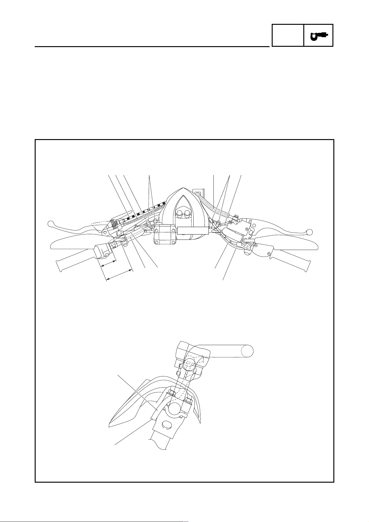
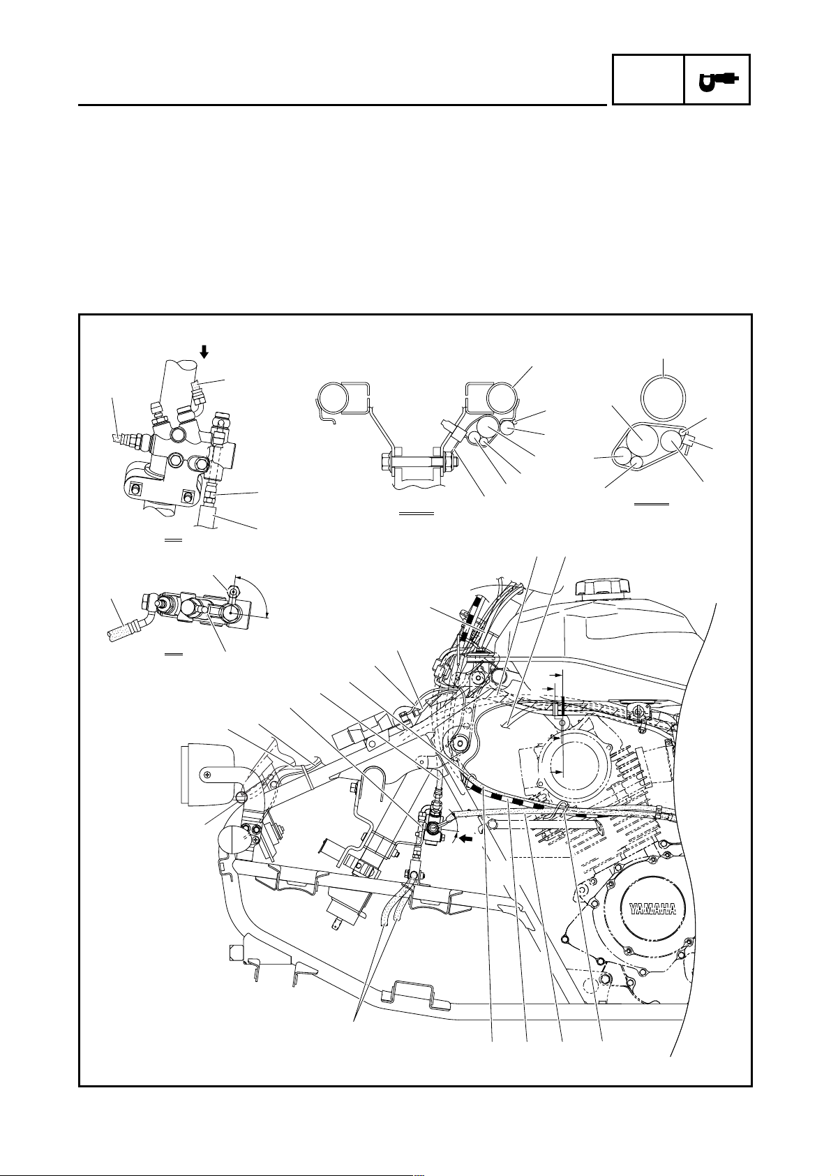
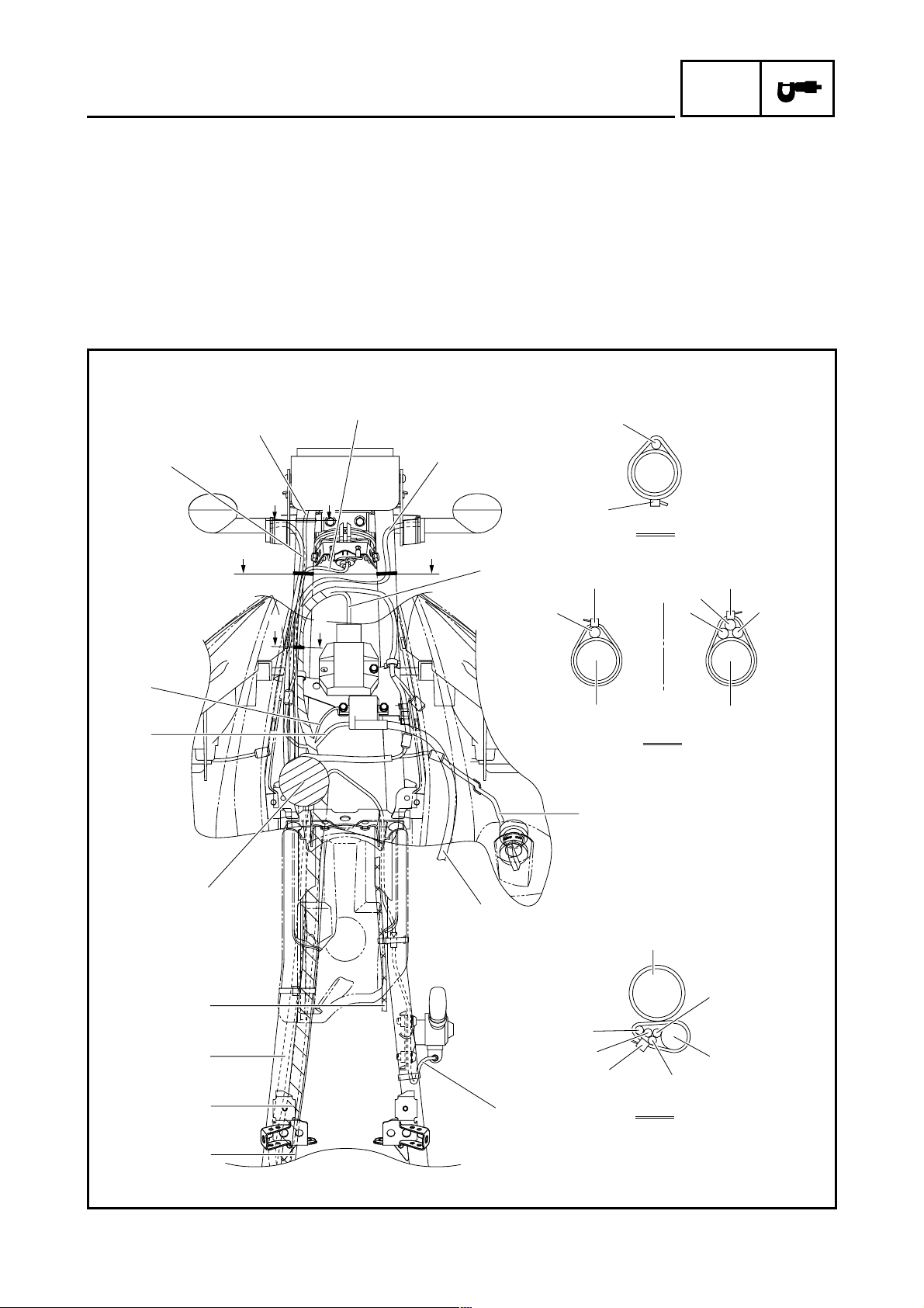
CABLE ROUTING
1 Clutch cable
2 Parking brake cable
3 Starter cable
4 Front brake hose
5 Front brake light switch lead
6 Engine stop switch lead
7 Throttle cable
8 Clutch switch lead
9 Handlebar switch lead
0 Meter assembly lead
CABLE ROUTING
È Fasten the clutch switch lead and handlebar
switch lead with plastic bands.
É Fasten the engine stop switch lead and front
brake light switch lead with plastic bands.
Ê 53 ~ 54 mm (2.09 ~ 2.13 in)
Ë 88 ~ 89 mm (3.46 ~ 3.50 in)
Ì Route the meter assembly lead along the han-
dlebar, and then pass it to the front of the lower
section of the handlebar.
SPEC
1
Ê
2
3
Ë
9
È
8
4
7
6
É
5
Ì
0
– 6 –

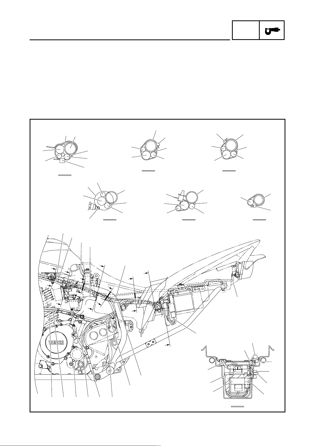
CABLE ROUTING
SPEC
1 Throttle cable
2 Front brake hose
3 Engine stop switch lead
4 Front brake light switch lead
5 Meter assembly lead
6 Parking brake cable
7 Clutch cable
8 Starter cable
9 Clutch switch lead
0 Handlebar switch lead
A Neutral/reverse indicator light lead
34 5
2
1
B Wire harness
C Front turn signal light lead (left)
D Front turn signal light lead (right)
E Rectifier/regulator lead
È Pass the clutch switch lead, handlebar switch
lead, neutral/reverse indicator light lead, front
brake light switch lead, starter cable, and engine
stop switch lead through the guide.
6
7
8
9
0
D
E
A
È
A
A
É
Ë
0
A
B
Ê
3
4
9
8
A-A
C
– 7 –
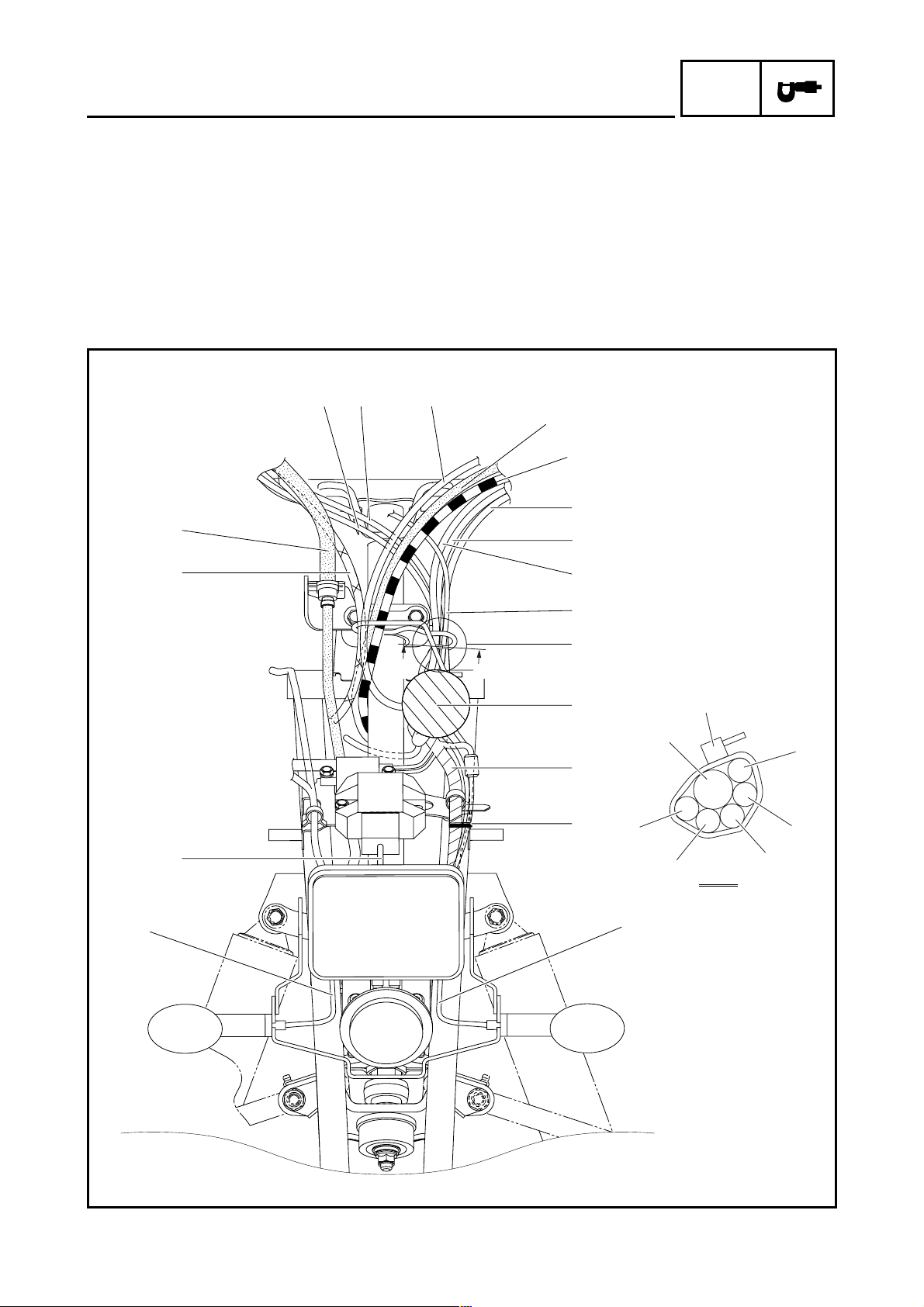
É Make sure that the lead connections are posi-
tioned in the area shown in the illustration.
Ê Fasten the wire harness, front turn signal light
lead (right), horn lead, headlight lead, and front
turn signal light lead (left) with a plastic locking
tie.
Ë Fasten the handlebar switch lead, neutral/
reverse indicator light lead, clutch switch lead,
starter cable, front brake light switch lead, and
engine stop switch lead with a plastic locking tie.
34 5
2
CABLE ROUTING
6
7
8
9
SPEC
D
1
E
0
A
È
A
A
É
B
Ê
3
C
0
4
Ë
A
9
8
A-A
– 8 –

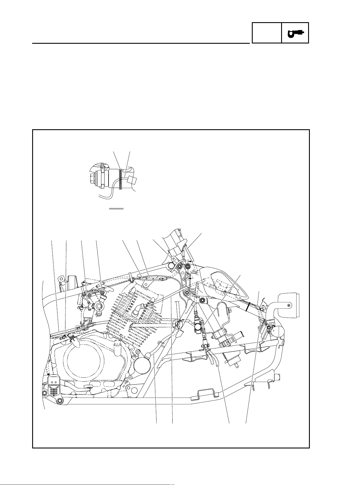
CABLE ROUTING
SPEC
1 Headlight lead
2 Front turn signal light lead (left)
3 Brake hose (brake equalizer to brake hose joint)
4 Front brake hose
5 Ground lead
6 Ignition coil lead
7 Starter cable
8 Wire harness
9 Starter motor lead
0 Brake hose (rear brake master cylinder to brake
equalizer)
D
4
0
3
A Clutch cable
B Parking brake cable
C Brake hose (brake hose joint to front brake cali-
per)
D Brake hose joint
E Frame
F Speed sensor lead
G Sub-wire harness
E
F
8
E
G
9
7
C-C
B-B
Ì
9
8
7
F
Í
G
0
A
D
8
9
3
Î
7
D
4
È
4
6
5
C
B
3
2
1
B
C
Ë
Ê
A
C
– 9 –
BA0
É
CABLE ROUTING
SPEC
È Pass the parking brake cable and clutch cable
through the cable guide.
É Pass the parking brake cable, clutch cable, and
brake hose (rear brake master cylinder to brake
equalizer) through the cable guide.
Ê 25°
Ë Route the headlight lead so that it does not con-
tact the front panel.
Ì Fasten the wire harness, starter motor lead, and
starter cable with a plastic band. Face the end of
the plastic band down.
D
4
0
3
Í Fasten the speed sensor lead, sub-wire har-
ness, wire harness, starter cable, and starter
motor lead with a plastic locking tie.
Î 90°
E
F
8
E
G
9
7
C-C
B-B
Ì
9
8
7
F
Í
G
0
A
D
8
9
3
Î
7
D
4
È
4
6
5
C
B
3
2
1
B
C
Ë
Ê
A
C
– 10 –
BA0
É
CABLE ROUTING
SPEC
1 Starter cable
2 Fuel hose
3 Carburetor air vent hose
4 Crankcase breather hose
5 Speed sensor lead
6 Tail/brake light lead
7 C.D.I. unit lead
8 Wire harness
9 Reverse switch lead
0 Negative battery lead
A Carburetor overflow hose
B A.C. magneto lead
1
F
8
H
5
G
È
A-A
É
8
1
C Neutral switch lead
D Brake hose (rear brake master cylinder to brake
E Parking brake cable
F Frame
G Sub-wire harness
H Starter motor lead
I Starting circuit cut-off relay
J C.D.I. unit
K Starter relay
L Positive battery lead
F
Ê
H
8
5
G
C-C E-E
H
F
5
B-B D-D
G
Ë
8
H
equalizer)
F
G
H
5
8
Ê
G
F
5
G
F
Ì
F-F
1
2
3
4
A
B
D
C
A
E
C
B
E
D
EDCBA0
5
F
F
9
G
8
G
7
L
K
J
6
G
Í
Î
H
0
I
G-G
– 11 –

CABLE ROUTING
SPEC
È Pass a plastic band through the hole in the fuel
tank shield, and then fasten the wire harness,
starter motor lead, starter cable, speed sensor
lead, and sub-wire harness with the plastic
band. The end of the plastic band should be
under the frame, facing inward.
É Route the wire harness, starter motor lead,
speed sensor lead, and sub-wire harness above
the starter cable.
Ê Fasten the wire harness, starter motor lead,
speed sensor lead, and sub-wire harness with a
plastic locking tie.
1
F
8
H
5
G
È
H
8
C-C E-E
A-A
H
É
F
8
5
G
1
B-B D-D
Ë Fasten the wire harness and starter motor lead
with a plastic band. Face the end of the plastic
band inward.
Ì Fasten the sub-wire harness with a plastic lock-
ing tie.
Í Connect the sub-wire harness to the wire har-
ness.
Î Connect the tail/brake light lead to the wire har-
ness.
F
Ê
5
G
Ë
8
H
F
G
H
5
8
Ê
F
5
G
G
F-F
F
Ì
1
2
3
4
A
B
D
C
A
E
C
B
E
D
EDCBA0
5
F
F
9
G
8
G
7
L
K
J
6
G
Í
Î
H
0
I
G-G
– 12 –
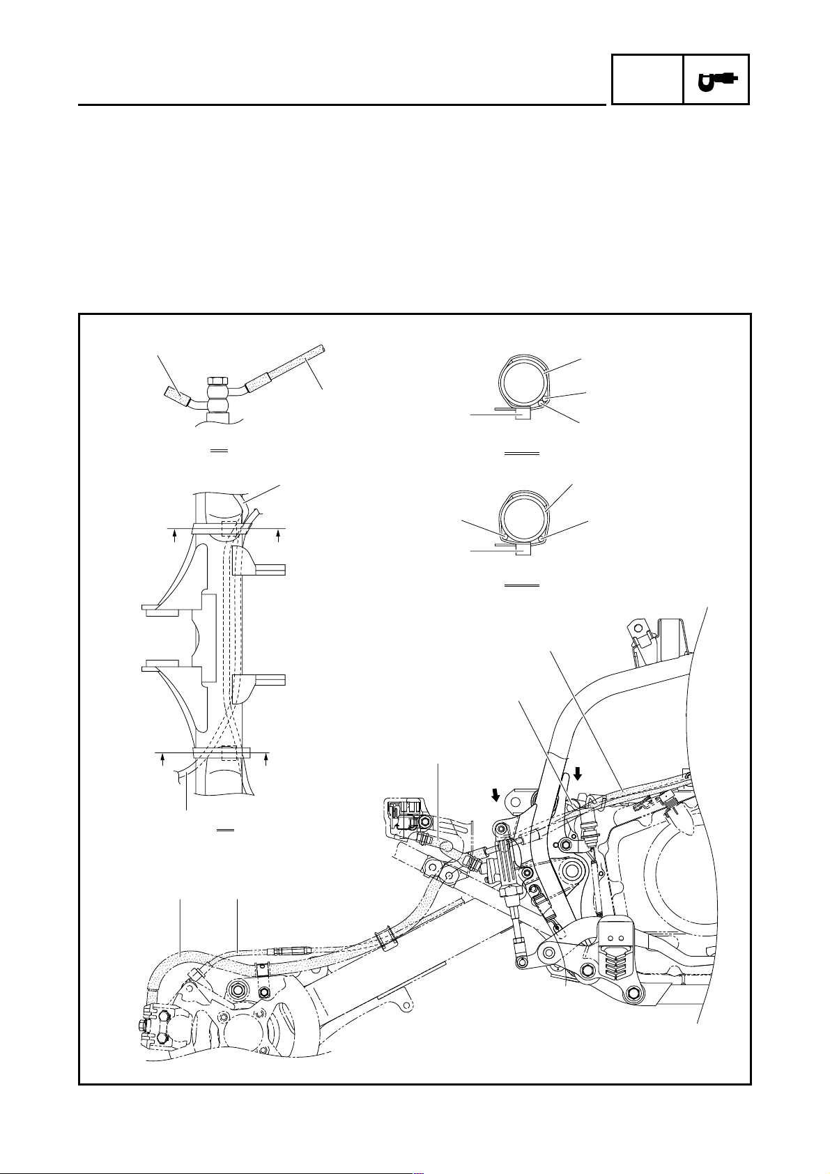
CABLE ROUTING
SPEC
1 Brake hose (rear brake master cylinder to brake
equalizer)
2 Parking brake cable
3 Drive select lever switch lead
4 Ground terminal
5 Throttle cable
6 Main switch lead
7 Front brake hose
8 Brake hose (brake equalizer to brake hose joint)
9 Front turn signal light lead (right)
0 Horn lead
È
D
A-A
A Brake hose (brake hose joint to front brake cali-
per)
B Spark plug lead
C Starter motor lead
D Headlight lead (not used)
È Fasten the headlight lead (not used) with a plas-
tic locking tie. Also, fasten the wire harness with
a plastic locking tie in the same way on the left
side of the vehicle.
1234 356
7
A
8
A
9
– 13 –
A0CB
CABLE ROUTING
SPEC
1 Rear brake hose
2 Parking brake cable
3 Brake fluid reservoir hose
4 Rear brake light switch lead
5 Brake hose (rear brake master cylinder to brake
equalizer)
6 Speed sensor lead
7 Frame
1
5
A
4
È Fasten the rear brake light switch lead and
speed sensor lead with the plastic band.
7
6
È
C-C
6
4
7
4
C
D
6
12
B
C
D
3
È
D-D
5
4
B
A
– 14 –
CABLE ROUTING
SPEC
1 Front turn signal light lead (left)
2 Horn lead
3 Headlight lead
4 Front turn signal light lead (right)
5 Rectifier/regulator lead
6 Main switch lead
7 Spark plug lead
8 Drive select lever switch lead
9 Starter motor lead
0 Wire harness
A Sub-wire harness
2
1
A
B
C
C
B Throttle cable
C Ignition coil lead
D Ground lead
E Frame
3
2
4
A
É
A-A
B
5
4
Ê
3
2
Ë
1
D
C
È
B
A
0
7
8
6
1
3
E
Ì
E
B-B
E
4
0
2
C-C
9
– 15 –
 Loading...