

Page 1

2009
SERVICE MANUAL
YFM25RY
YFM25RSEY
YFM25RSE2Y
4D3-28197-11LIT-11616-22-09
Page 2

EAS20040
YFM25RY/YFM25RSEY/YFM25RSE2Y
SERVICE MANUAL
©2008 by Yamaha Motor
Corporation, U.S.A.
First edition, April 2008
All rights reserved. Any reproduction
or unauthorized use without the written
permission of Yamaha Motor Corporation,
U.S.A. is expressly prohibited.
Printed in U.S.A.
P/N LIT-11616-22-09
Page 3
EAS20071
IMPORTANT
This manual was produced by the Yamaha Motor Company, Ltd. primarily for use by Yamaha dealers and their qualified mechanics. It is not possib le to include all the kno wledge of a mechan ic in one
manual. Therefore, anyone who uses this book to perform maintenance and repairs on Yamaha
vehicles should have a basic understanding of mechanics and the techniques to repair these types
of vehicles. Repair and maintenance work attempted by anyone without this knowledge is likely to
render the vehicle unsafe and unfit for use.
This model has been designed and manufactured to perform within certain specifications in regard
to performance and emissions. Proper service with the correct tools is necessary to ensure that the
vehicle will operate as designed. If there is any question about a service procedure, it is imperative
that you contact a Yamaha dealer f or an y se rvice information changes that apply to this model. This
policy is intended to provide the customer with the most satisf action from his vehicle and to conform
to federal environmental quality objectives.
Yamaha Motor Company, Ltd. is continually striving to improve all of its models. Modifications and
significant changes in specifications or procedures will be forwarded to all authorized Yamaha dealers and will appear in future editions of this manual where applicable.
TIP
• This Service Manual contains information regarding periodic maintenance to the emission control
system. Please read this material carefully.
• Designs and specifications are subject to change without notice.
EAS20081
IMPORTANT MANUAL INFORMATION
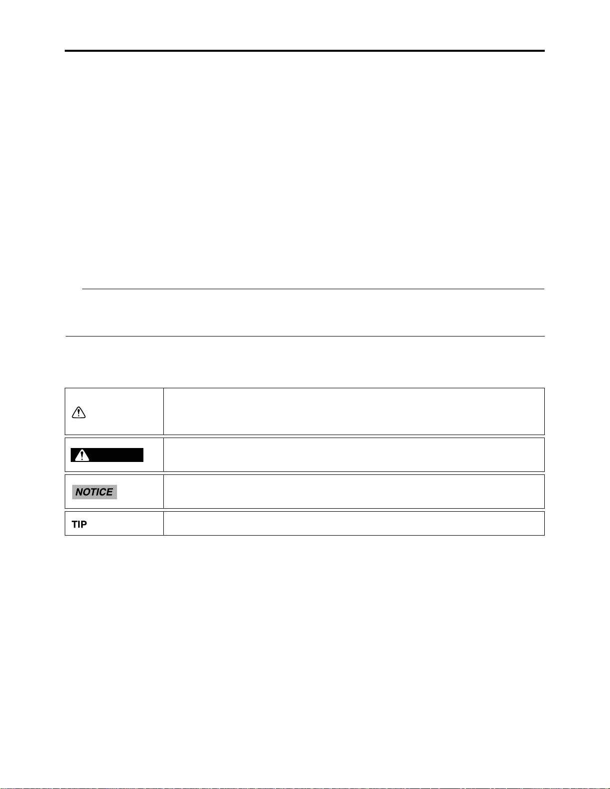
Particularly important information is distinguished in this manual by the following notations.
This is the safety alert symbol. It is used to alert you to potential personal injury hazards. Obey all safety messages that follow this symbol
to avoid possible injury or death.
A WARNING indicates a hazardous situation which, if not avoided,
WARNING
could result in death or serious injury.
A NOTICE indicates special precautions that must be taken to avoid
damage to the vehicle or other property.
A TIP provides key information to make procedures easier or clearer.
Page 4
EAS20090
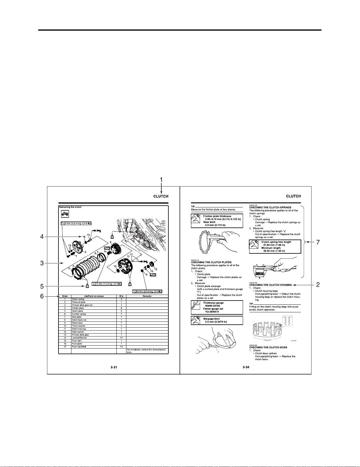
HOW TO USE THIS MANUAL
This manual is intended as a handy, easy-to-read reference book f or the mechanic. Comprehensive
explanations of all installation, removal, disassembly, assembly, repair and check procedures are
laid out with the individual steps in sequential order.
• The manual is divided into chapters and each chapter is divided into sections . The current section
title is shown at the top of each page “1”.
• Sub-section titles appear in smaller print than the section title “2”.
• To help identify parts and clarify procedure steps, there are exploded diagr ams at the start of each
removal and disassembly section “3”.
• Numbers are given in the order of the jobs in the exploded diagram. A number indicates a disassembly step “4”.
• Symbols indicate parts to be lubricated or replaced “5”.
Refer to “SYMBOLS”.
• A job instruction chart accompanies the exploded diagram, providing the order of jobs, names of
parts, notes in jobs, etc “6”.
• Jobs requiring more information (such as special tools and technical data) are described sequentially “7”.
Page 5
EAS20100
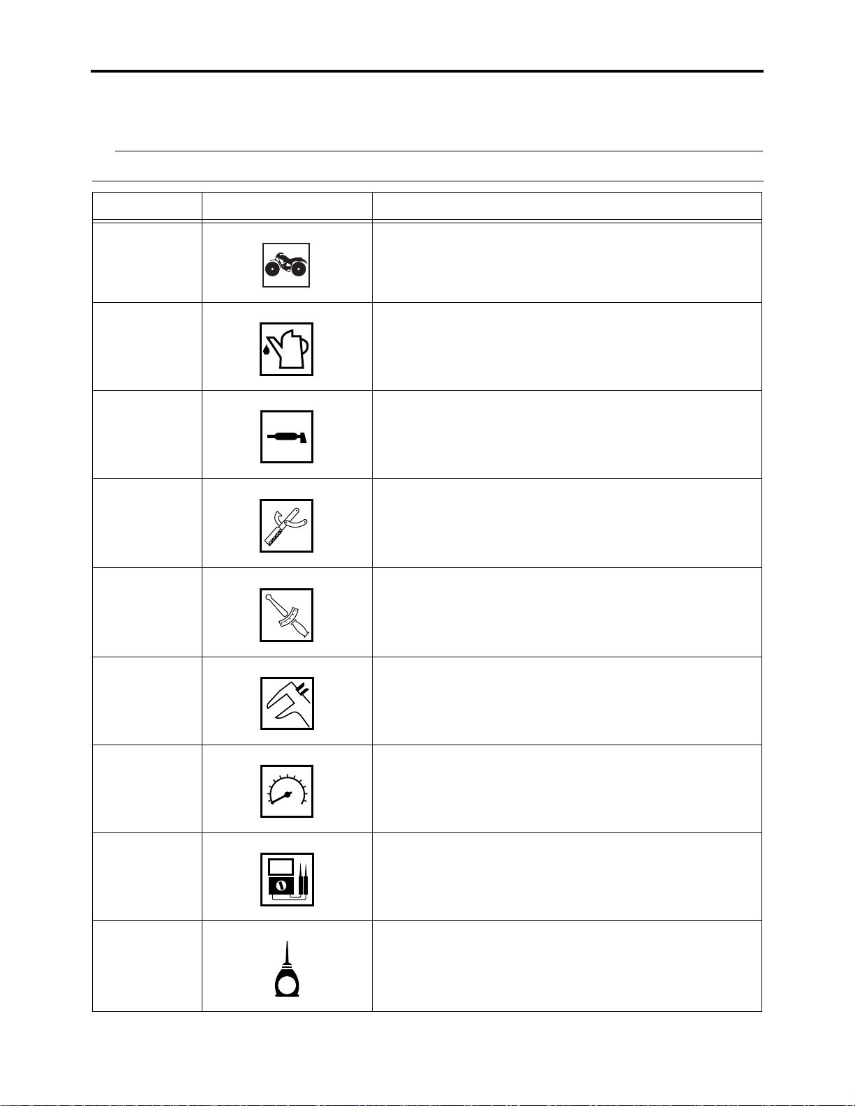
SYMBOLS
The following symbols are used in this manual for easier understanding.
TIP
The following symbols are not relevant to every vehicle.
No SYMBOL DEFINITION
1 Serviceable with engine mounted
2 Filling fluid
3 Lubricant
4 Special tool
5 Tightening torque
T
.
R
.
6 Wear limit, clearance
7 Engine speed
8 Electrical data
9 Engine oil
E
Page 6

No SYMBOL DEFINITION
10 Gear oil
G
11 Molybdenum-disulfide oil
M
12 Brake fluid
BF
13 Wheel-bearing grease
14 Lithium-soap-based grease
15 Molybdenum-disulfide grease
16 Silicone grease
B
LS
M
S
17 Apply locking agent (LOCTITE®)
LT
18 Replace the part
New
Page 7

EAS20110
TABLE OF CONTENTS
GENERAL INFORMATION
SPECIFICATIONS
PERIODIC CHECKS AND ADJUSTMENTS
CHASSIS
ENGINE
1
2
3
4
5
FUEL SYSTEM
ELECTRICAL SYSTEM
TROUBLESHOOTING
6
7
8
Page 8

Page 9

GENERAL INFORMATION
IDENTIFICATION..........................................................................................1-1
VEHICLE IDENTIFICATION NUMBER...................................................1-1
MODEL LABEL.......................................................................................1-1
IMPORTANT INFORMATION.......................................................................1-2
PREPARATION FOR REMOVAL AND DISASSEMBLY..........................1-2
REPLACEMENT PARTS.........................................................................1-2
GASKETS, OIL SEALS AND O-RINGS..................................................1-3
LOCK WASHERS/PLATES AND COTTER PINS...................................1-3
BEARINGS AND OIL SEALS.................................................................1-3
CIRCLIPS ...............................................................................................1-3
CHECKING THE CONNECTIONS ...............................................................1-4
SPECIAL TOOLS..........................................................................................1-5
1
Page 10
EAS20130
IDENTIFICATION
EAS20140
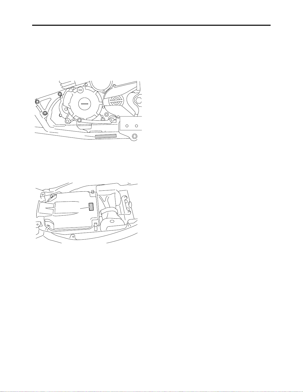
VEHICLE IDENTIFICATION NUMBER
The vehicle identification number “1” is
stamped into the right side of the steering
head pipe.
1
EAS20150
MODEL LABEL
The model label “1” is affixed to the frame . This
information will be needed to order spare
parts.
IDENTIFICATION
1
1-1
Page 11

EAS20180
IMPORTANT INFORMATION
EAS20190
PREPARATION FOR REMOVAL AND DISASSEMBLY
1. Before removal and disassembly, remove
all dirt, mud, dust and foreign material.
2. Use only the proper tools and cleaning
equipment.
Refer to “SPECIAL TOOLS” on page 1-5.
3. When disassembling, always keep mated
parts together. This includes gears, cylinders, pistons and other parts that have
been “mated” through normal wear. Mated
parts must always be reused or replaced
as an assembly.
IMPORTANT INFORMATION
4. During disassembly, clean all of the parts
and place them in trays in the order of disassembly. This will speed up assembly and
allow for the correct installation of all parts.
5. Keep all parts away from any source of fire.
EAS20200
REPLACEMENT PARTS
Use only genuine Yamaha parts for all replacements. Use oil and grease recommended by
Yamaha for all lubrication jobs. Other brands
may be similar in function and appearance , but
inferior in quality.
1-2
Page 12
EAS20210
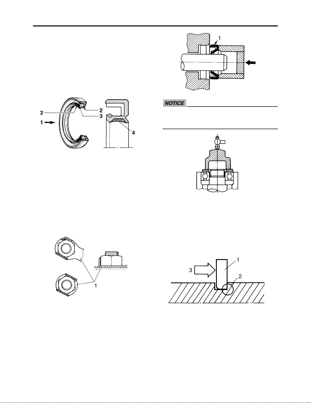
GASKETS, OIL SEALS AND O-RINGS
1. When overhauling the engine, replace all
gaskets, seals and O-rings. All gasket surfaces, oil seal lips and O-rings must be
cleaned.
2. During reassembly, properly oil all mating
parts and bearings and lubricate the oil
seal lips with grease.
IMPORTANT INFORMATION
ECA13300
Do not spin the bearing with compressed
air because this will damage the bearing
surfaces.
1. Oil
2. Lip
3. Spring
4. Grease
EAS20220
LOCK WASHERS/PLATES AND COTTER
PINS
After removal, replace all lock washers/plates
“1” and cotter pins. After the bolt or nut has
been tightened to specification, bend the lock
tabs along a flat of the bolt or nut.
EAS20230
BEARINGS AND OIL SEALS
Install bearings and oil seals so that the manufacturer’s mar ks or numbers are visible. When
installing oil seals “1”, lubricate the oil seal lips
with a light coat of lithium-soap-based grease.
Oil bearings liberally when installing, if appropriate.
EAS20240
CIRCLIPS
Before reassembly, check all circlips carefully
and replace damaged or distorted circlips.
Always replace piston pin clips after one use.
When installing a circlip “1”, make sure the
sharp-edged corner “2” is positioned opposite
the thrust “3” that the circlip receives.
1-3
Page 13

EAS20250
CHECKING THE CONNECTIONS
Check the leads, couplers, and connectors for
stains, rust, moisture, etc.
1. Disconnect:
• Lead
• Coupler
• Connector
2. Check:
• Lead
• Coupler
• Connector
Moisture → Dry with an air blower.
Rust/stains → Connect and disconnect
sev eral times.
CHECKING THE CONNECTIONS
Pocket tester
90890-03112
Analog pocket tester
YU-03112-C
TIP
• If there is no continuity, clean the terminals.
• When checking the wire harness, perform
steps (1) to (3).
• As a quick remedy, use a contact revitalizer
available at most part stores.
3. Check:
• All connections
Loose connection → Connect properly.
TIP
If the pin “1” on the terminal is flattened, bend
it up.
4. Connect:
• Lead
• Coupler
• Connector
TIP
Make sure all connections are tight.
5. Check:
• Continuity
(with the pocket tester)
1-4
Page 14
SPECIAL TOOLS
EAS20260
SPECIAL TOOLS
The following special tools are necessary for complete and accurate tune-up and assembly. Use
only the appropriate special tools as this will help prevent damage caused by the use of inappropriate tools or improvised techniques. Special tools , part numbers or both ma y differ depending on the
country.
When placing an order, refer to the list provided below to avoid any mistakes.
TIP
• For U.S.A. and Canada, use part number starting with “YM-”, “YU-”, or “ACC-”.
• For others, use part number starting with “90890-”.
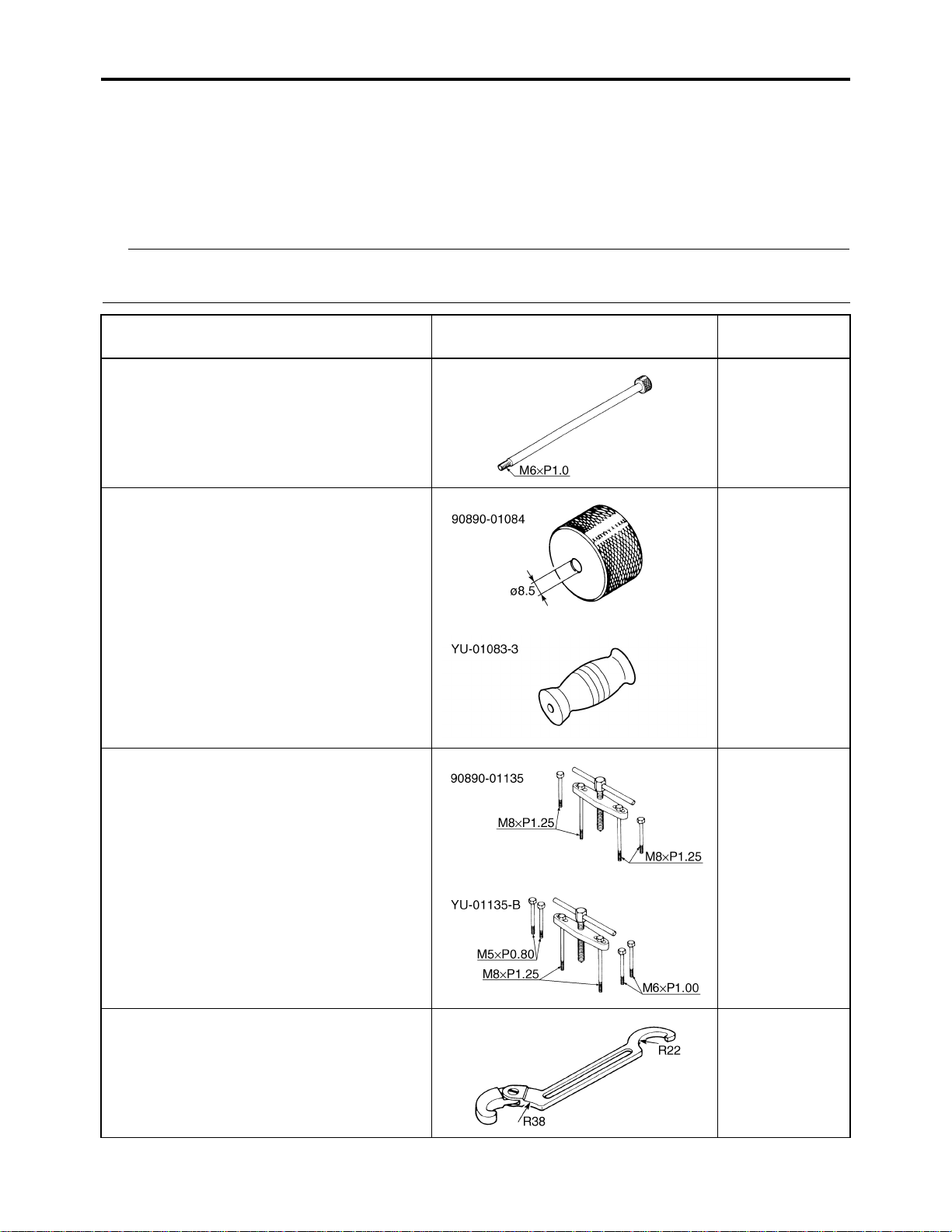
Tool name/Tool No. Illustration
Slide hammer bolt
90890-01083
Slide hammer bolt 6 mm
YU-01083-1
Weight
90890-01084
YU-01083-3
Crankcase separating tool
90890-01135
Crankcase separator
YU-01135-B
Reference
pages
5-7
5-7
5-58
Ring nut wrench
90890-01268
Spanner wrench
YU-01268
3-24
1-5
Page 15
SPECIAL TOOLS
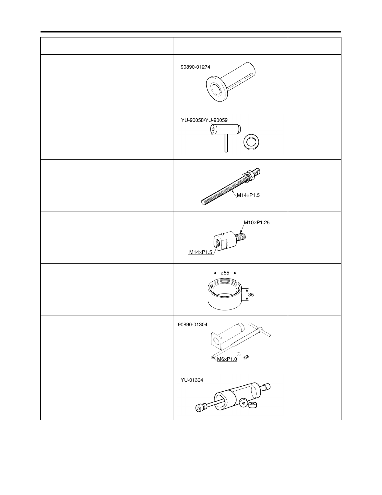
Tool name/Tool No. Illustration
Crankshaft installer pot
90890-01274
Installing pot
YU-90058
Crankshaft installer bolt
90890-01275
Bolt
YU-90060
Adapter (M10)
90890-01383
Adapter #2
YU-90062
Reference
pages
5-60
5-60
5-60
Spacer
90890-01288
Piston pin puller set
90890-01304
Piston pin puller
YU-01304
5-60
5-25
1-6
Page 16

SPECIAL TOOLS
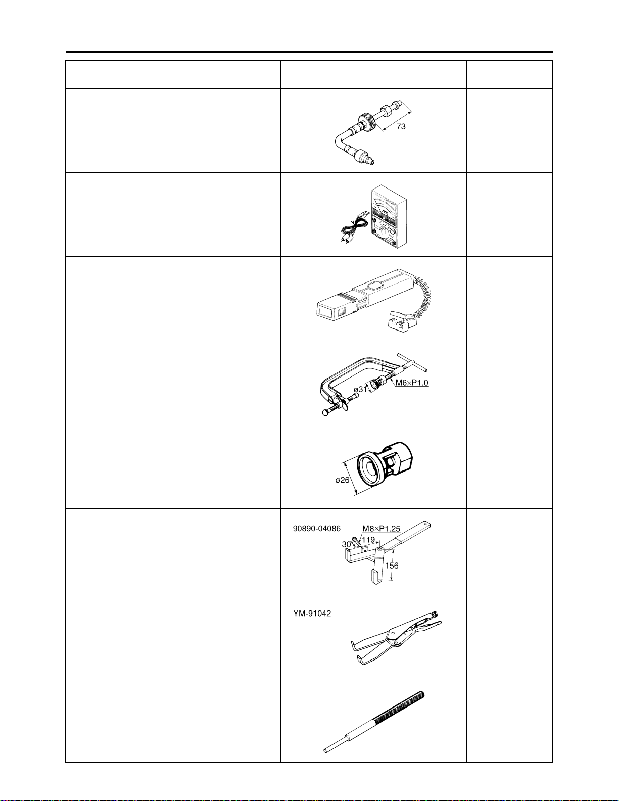
Tool name/Tool No. Illustration
Tappet adjusting tool
90890-01311
Six piece tappet set
YM-A5970
Flywheel puller
90890-01362
Heavy duty puller
YU-33270-B
Bolt (M8 × 80 mm)
90890-01359
Reference
pages
3-5
5-46
5-46
Sheave holder
90890-01701
Primary clutch holder
YS-01880-A
Thickness gauge
90890-03180
Feeler gauge set
YU-26900-9
Compression gauge
90890-03081
Engine compression tester
YU-33223
5-46, 5-47
3-4, 5-33
3-9
1-7
Page 17
SPECIAL TOOLS
Tool name/Tool No. Illustration
Extension
90890-04082
Pocket tester
90890-03112
Analog pocket tester
YU-03112-C
Timing light
90890-03141
Inductive clamp timing light
YU-03141
Valve spring compressor
90890-04019
YM-04019
Reference
pages
3-9
1-4, 5-51, 7-31,
7-32, 7-33, 737, 7-38, 7-39,
7-40, 7-41, 7-42
3-8
5-17, 5-22
Valve spring compressor attachment
90890-01243
Valve spring compressor adapter (26 mm)
YM-01253-1
Universal clutch holder
90890-04086
YM-91042
Valve guide remover (ø6)
90890-04064
Valve guide remover (6.0 mm)
YM-04064-A
5-17, 5-22
5-32, 5-34
5-19
1-8
Page 18
SPECIAL TOOLS
Tool name/Tool No. Illustration
Valve guide installer (ø6)
90890-04065
Valve guide installer (6.0 mm)
YM-04065-A
Valve guide reamer (ø6)
90890-04066
Valve guide reamer (6.0 mm)
YM-04066
Valve lapper
90890-04101
Valve lapping tool
YM-A8998
PTT wrench 46
90890-06588
Axle nut wrench (46 mm)
YM-37134
Reference
pages
5-19
5-19
5-20
4-13, 4-14
Ignition checker
90890-06754
Opama pet-4000 spark checker
YM-34487
Digital tachometer
90890-06760
YU-39951-B
Yamaha bond No. 1215
(Three Bond No.1215®)
90890-85505
7-39
3-5, 3-8
5-55
1-9
Page 19

SPECIFICATIONS
GENERAL SPECIFICATIONS......................................................................2-1
ENGINE SPECIFICATIONS..........................................................................2-4
CHASSIS SPECIFICATIONS......................................................................2-10
ELECTRICAL SPECIFICATIONS...............................................................2-12
TIGHTENING TORQUES............................................................................2-14
GENERAL TIGHTENING TORQUE SPECIFICATIONS.......................2-14
ENGINE TIGHTENING TORQUES......................................................2-15
CHASSIS TIGHTENING TORQUES....................................................2-17
LUBRICATION POINTS AND LUBRICANT TYPES..................................2-19
ENGINE................................................................................................2-19
LUBRICATION SYSTEM CHART AND DIAGRAMS .................................2-21
ENGINE OIL LUBRICATION CHART...................................................2-21
LUBRICATION DIAGRAMS..................................................................2-23
2
CABLE ROUTING ......................................................................................2-29
Page 20

GENERAL SPECIFICATIONS
EAS29110
GENERAL SPECIFICATIONS
Model
Model 4D3D/4D3H/4D3M
Dimensions
Overall length 1625 mm (64.0 in)
Overall width 1070 mm (42.1 in)
Overall height 1040 mm (40.9 in)
Seat height 730 mm (28.7 in)
Wheelbase 1110 mm (43.7 in)
Ground clearance 100 mm (3.9 in)
Minimum turning radius 2900 mm (114 in)
Weight
With oil and fuel 150.0 kg (331 lb)
Engine
Engine type Air cooled 4-stroke, SOHC
Cylinder arrangement Forward-inclined single cylinder
Displacement 249.0 cm
Bore × stroke 74.0 × 58.0 mm (2.91 × 2.28 in)
Compression ratio 9.50 : 1
Standard compression pressure (at sea level) 1100 kPa/720 r/min (11.0 kgf/cm
156.5 psi/720 r/min)
Starting system Electric starter
Lubrication system Wet sump
Engine oil
Type YAMALUBE 4 (10W-40) or SAE 10W-40,
YAMALUBE 4 (20W-50) or SAE 20W-50
Recommended engine oil grade API service SG type or higher, JASO standard
MA
Engine oil quantity
Without oil filter element replacement 1.25 L (1.32 US qt, 1.10 Imp.qt)
With oil filter element replacement 1.35 L (1.43 US qt, 1.19 Imp.qt)
Total amount 1.60 L (1.69 US qt, 1.41 Imp.qt)
Oil filter
Oil filter type Paper
Air filter
Air filter element Wet element
Air filter oil grade Foam air filter oil or equivalent oil
Fuel
Recommended fuel Unleaded gasoline only
Fuel tank capacity 9.0 L (2.38 US gal, 1.98 Imp.gal)
Fuel reserve amount 1.0 L (0.26 US gal, 0.22 Imp.gal)
Carburetor
Type × quantity BSR29 × 1
Manufacturer MIKUNI
3
2
/720 r/min,
2-1
Page 21

GENERAL SPECIFICATIONS
Spark plug (s)
Manufacturer/model NGK/DR7EA
Spark plug gap 0.6–0.7 mm (0.024–0.028 in)
Clutch type Wet, multiple-disc
Transmission
Primary reduction system Spur gear
Primary reduction ratio 76/22 (3.455)
Secondary reduction system Chain drive
Secondary reduction ratio 38/14 (2.714)
Transmission type Constant mesh 5-speed
Operation Left foot operation
1st 37/13 (2.846)
2nd 33/18 (1.833)
3rd 29/21 (1.381)
4th 27/24 (1.125)
5th 28/29 (0.966)
Chassis
Frame type Steel tube frame
Caster angle 6 °
Camber angle -1.5 °
Kingpin angle 14.8 °
Trail 23.0 mm (0.91 in)
Tread rear (STD) 824.0 mm (32.44 in)
Tread front (STD) 826.0 mm (32.52 in)
Toe-in (with tire touching the ground) 9.0–19.0 mm (0.35–0.75 in)
Front tire
Type Tubeless
Size AT20 × 7-10
Manufacturer/model DUNLOP/KT201
Rear tire
Type Tubeless
Size AT19 × 10-9
Manufacturer/model DUNLOP/KT205A
Tire air pressure (measured on cold tires)
Maximum loading limit 100.0 kg (220 lb)
Off-road riding
Front 27.5 kPa (0.28 kgf/cm
Rear 27.5 kPa (0.28 kgf/cm
Front brake
Type Dual disc brake
Operation Right hand operation
Rear brake
Type Single disc brake
Operation Right foot operation
Front suspension
Type Double wishbone
Spring/shock absorber type Coil spring/oil damper (4D3D)
Coil spring/gas-oil damper (4D3H, 4D3M)
Wheel travel 190 mm (7.5 in)
2
, 4.0 psi)
2
, 4.0 psi)
2-2
Page 22

GENERAL SPECIFICATIONS
Rear suspension
Type Swingarm
Spring/shock absorber type Coil spring/gas-oil damper
Wheel travel 200 mm (7.9 in)
Electrical system
Ignition system DC. CDI
Charging system AC magneto
Model YTZ7S
Voltage, capacity 12 V, 6.0 Ah
Headlight
Bulb type Krypton bulb
Bulb voltage, wattage × quantity
Headlight 12 V, 30.0/30.0 W × 2
Tail/brake light 12 V, 5.0/21.0 W × 1 (4D3D)
12 V, 0.5/3.9 W × 1 (4D3H, 4D3M)
Neutral indicator light 12 V, 1.7 W × 1
2-3
Page 23
EAS29120
ENGINE SPECIFICATIONS
ENGINE SPECIFICATIONS
Cylinder head
Volume 20.50–21.50 cm
3
(1.25–1.31 cu.in)
Warpage limit 0.05 mm (0.0020 in)
Cylinder
Bore 74.000–74.016 mm (2.9134–2.9140 in)
Wear limit 74.100 mm (2.9173 in)
Camshaft
Drive system Chain drive (right)
Camshaft lobe dimensions
Intake A 36.890–36.990 mm (1.4524–1.4563 in)
Limit 36.790 mm (1.4484 in)
Intake B 30.111–30.211 mm (1.1855–1.1894 in)
Limit 30.011 mm (1.1815 in)
Exhaust A 36.891–36.991 mm (1.4524–1.4563 in)
Limit 36.791 mm (1.4485 in)
Exhaust B 30.092–30.192 mm (1.1847–1.1887 in)
Limit 29.992 mm (1.1808 in)
Camshaft runout limit 0.030 mm (0.0012 in)
Timing chain
Model/number of links DID SCR-0404 SV/104
Tensioning system Automatic
Rocker arm/rocker arm shaft
Rocker arm inside diameter 12.000–12.018 mm (0.4724–0.4731 in)
Limit 12.036 mm (0.4739 in)
Rocker arm shaft outside diameter 11.981–11.991 mm (0.4717–0.4721 in)
Limit 11.950 mm (0.4705 in)
Rocker-arm-to-rocker-arm-shaft clearance 0.009–0.037 mm (0.0004–0.0015 in)
2-4
Page 24
ENGINE SPECIFICATIONS
Valve, valve seat, valve guide
Valve clearance (cold)
Intake 0.05–0.10 mm (0.0020–0.0039 in)
Exhaust 0.10–0.15 mm (0.0039–0.0059 in)
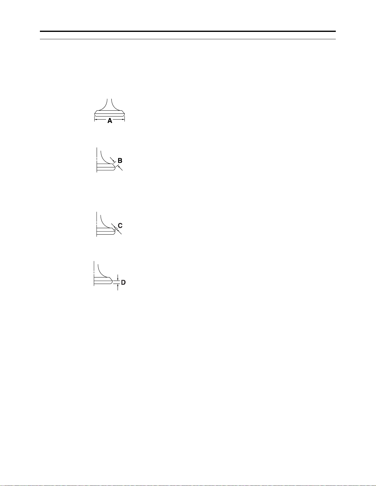
Valve dimensions
Valve head diameter A (intake) 33.90–34.10 mm (1.3346–1.3425 in)
Valve head diameter A (exhaust) 28.40–28.60 mm (1.1181–1.1260 in)
Valve face width B (intake) 2.26 mm (0.0890 in)
Valve face width B (exhaust) 2.26 mm (0.0890 in)
Valve seat width C (intake) 0.90–1.10 mm (0.0354–0.0433 in)
Limit 1.60 mm (0.06 in)
Valve seat width C (exhaust) 0.90–1.10 mm (0.0354–0.0433 in)
Limit 1.60 mm (0.06 in)
Valve margin thickness D (intake) 0.80–1.20 mm (0.0315–0.0472 in)
Valve margin thickness D (exhaust) 0.80–1.20 mm (0.0315–0.0472 in)
Valve stem diameter (intake) 5.975–5.990 mm (0.2352–0.2358 in)
Limit 5.945 mm (0.234 in)
Valve stem diameter (exhaust) 5.960–5.975 mm (0.2346–0.2352 in)
Limit 5.930 mm (0.233 in)
Valve guide inside diameter (intake) 6.000–6.012 mm (0.2362–0.2367 in)
Limit 6.050 mm (0.238 in)
Valve guide inside diameter (exhaust) 6.000–6.012 mm (0.2362–0.2367 in)
Limit 6.050 mm (0.238 in)
Valve-stem-to-valve-guide clearance (intake) 0.010–0.037 mm (0.0004–0.0015 in)
Limit 0.080 mm (0.003 in)
Valve-stem-to-valve-guide clearance
(exhaust) 0.025–0.052 mm (0.0010–0.0020 in)
Limit 0.100 mm (0.004 in)
Valve stem runout limit 0.01 mm (0.0004 in)
Cylinder head valve seat width (intake) 0.90–1.10 mm (0.0354–0.0433 in)
Limit 1.60 mm (0.06 in)
Cylinder head valve seat width (exhaust) 0.90–1.10 mm (0.0354–0.0433 in)
Limit 1.60 mm (0.06 in)
2-5
Page 25
ENGINE SPECIFICATIONS
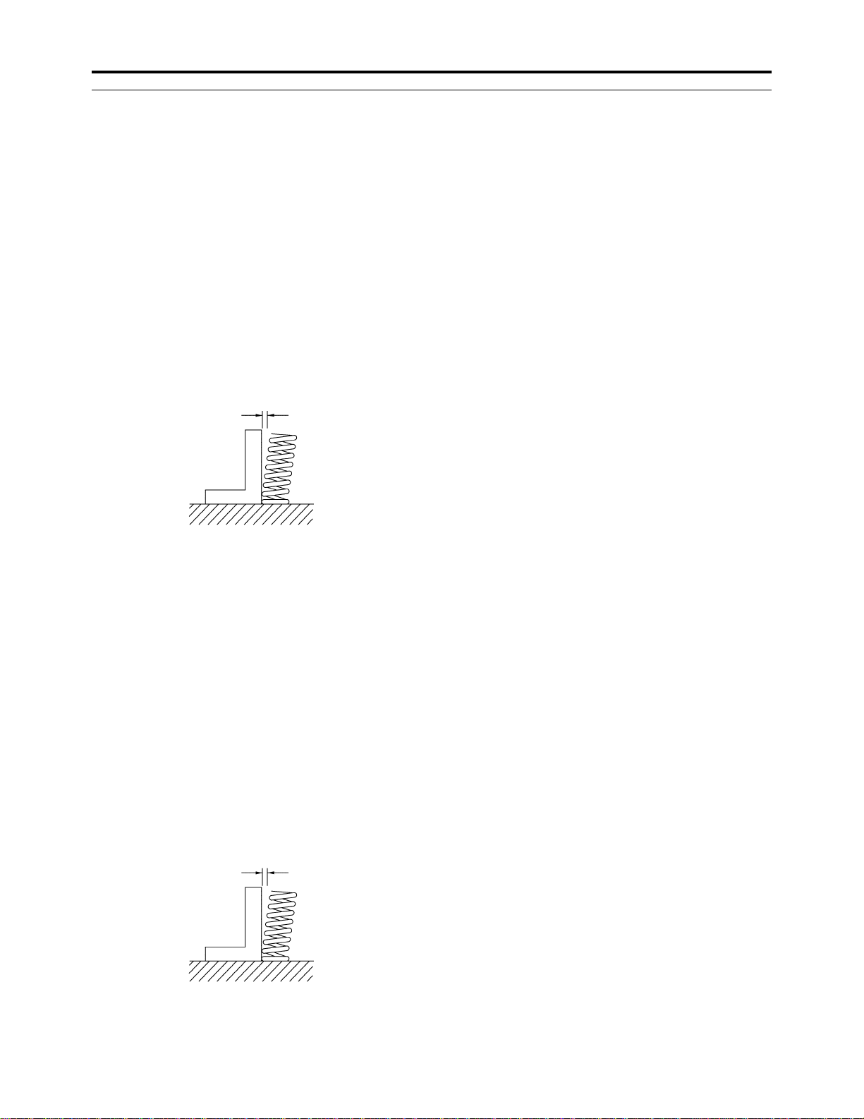
V alve spring
Inner spring
Free length (intake) 36.17 mm (1.42 in)
Limit 34.36 mm (1.35 in)
Free length (exhaust) 36.17 mm (1.42 in)
Limit 34.36 mm (1.35 in)
Installed length (intake) 30.50 mm (1.20 in)
Installed length (exhaust) 30.50 mm (1.20 in)
Spring rate K1 (intake) 14.70 N/mm (1.50 kgf/mm, 83.94 lbf/in)
Spring rate K2 (intake) 19.00 N/mm (1.94 kgf/mm, 108.49 lbf/in)
Spring rate K1 (exhaust) 14.70 N/mm (1.50 kgf/mm, 83.94 lbf/in)
Spring rate K2 (exhaust) 19.00 N/mm (1.94 kgf/mm, 108.49 lbf/in)
Installed compression spring force (intake) 75.00–91.70 N (7.65–9.35 kgf, 16.86–20.61
lbf)
Installed compression spring force (exhaust) 75.00–91.70 N (7.65–9.35 kgf, 16.86–20.61
Spring tilt (intake) 2.5 °/1.60 mm (2.5 °/0.063 in)
Spring tilt (exhaust) 2.5 °/1.60 mm (2.5 °/0.063 in)
lbf)
Winding direction (intake) Counterclockwise
Winding direction (exhaust) Counterclockwise
Outer spring
Free length (intake) 36.63 mm (1.44 in)
Limit 34.80 mm (1.37 in)
Free length (exhaust) 36.63 mm (1.44 in)
Limit 34.80 mm (1.37 in)
Installed length (intake) 32.00 mm (1.26 in)
Installed length (exhaust) 32.00 mm (1.26 in)
Spring rate K1 (intake) 30.90 N/mm (3.15 kgf/mm, 176.44 lbf/in)
Spring rate K2 (intake) 40.80 N/mm (4.16 kgf/mm, 232.97 lbf/in)
Spring rate K1 (exhaust) 30.90 N/mm (3.15 kgf/mm, 176.44 lbf/in)
Spring rate K2 (exhaust) 40.80 N/mm (4.16 kgf/mm, 232.97 lbf/in)
Installed compression spring force (intake) 128.50–157.90 N (13.10–16.10 kgf, 28.89–
35.50 lbf)
Installed compression spring force (exhaust) 128.50–157.90 N (13.10–16.10 kgf, 28.89–
35.50 lbf)
Spring tilt (intake) 2.5 °/1.60 mm (2.5 °/0.063 in)
Spring tilt (exhaust) 2.5 °/1.60 mm (2.5 °/0.063 in)
Winding direction (intake) Clockwise
Winding direction (exhaust) Clockwise
2-6
Page 26
ENGINE SPECIFICATIONS
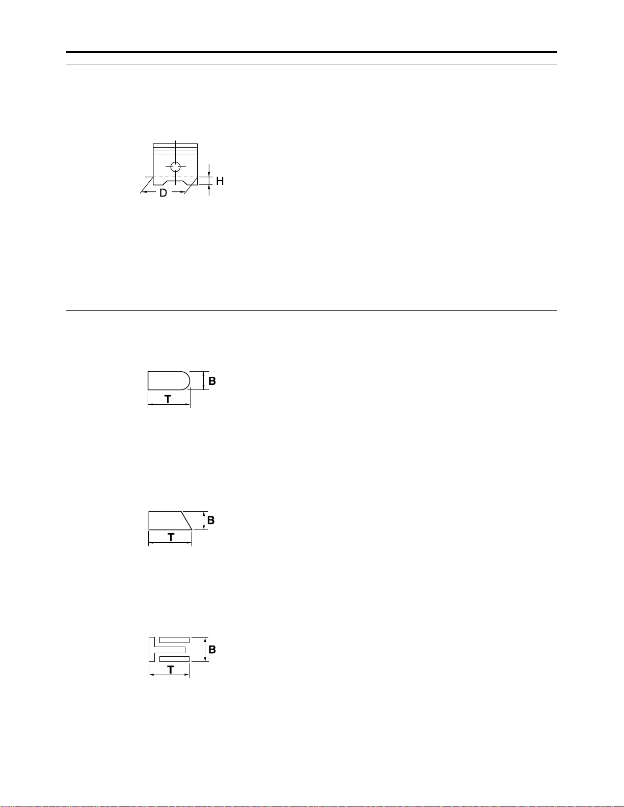
Piston
Piston-to-cylinder clearance 0.010–0.025 mm (0.0004–0.0010 in)
Limit 0.15 mm (0.0059 in)
Diameter D 73.983–73.998 mm (2.9127–2.9133 in)
Height H 5.0 mm (0.20 in)
Offset 0.25 mm (0.0098 in)
Offset direction Intake side
Piston pin bore inside diameter 17.002–17.013 mm (0.6694–0.6698 in)
Limit 17.043 mm (0.6710 in)
Piston pin outside diameter 16.991–17.000 mm (0.6689–0.6693 in)
Limit 16.971 mm (0.6681 in)
Piston-pin-to-piston-pin-bore clearance 0.002–0.022 mm (0.0001–0.0009 in)
Limit 0.072 mm (0.0028 in)
Piston ring
Top ring
Ring type Barrel
Dimensions (B × T) 0.90 × 2.75 mm (0.04 × 0.11 in)
End gap (installed) 0.19–0.31 mm (0.007–0.012 in)
Limit 0.56 mm (0.022 in)
Ring side clearance 0.030–0.065 mm (0.0012–0.0026 in)
Limit 0.115 mm (0.0045 in)
2nd ring
Ring type Taper
Dimensions (B × T) 0.80 × 2.80 mm (0.03 × 0.11 in)
End gap (installed) 0.30–0.45 mm (0.012–0.018 in)
Limit 0.80 mm (0.032 in)
Ring side clearance 0.020–0.055 mm (0.0008–0.0022 in)
Limit 0.115 mm (0.0045 in)
Oil ring
Dimensions (B × T) 1.50 × 2.60 mm (0.06 × 0.10 in)
End gap (installed) 0.10–0.35 mm (0.004–0.014 in)
2-7
Page 27
ENGINE SPECIFICATIONS
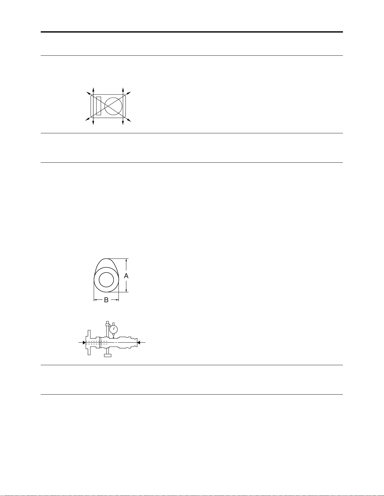
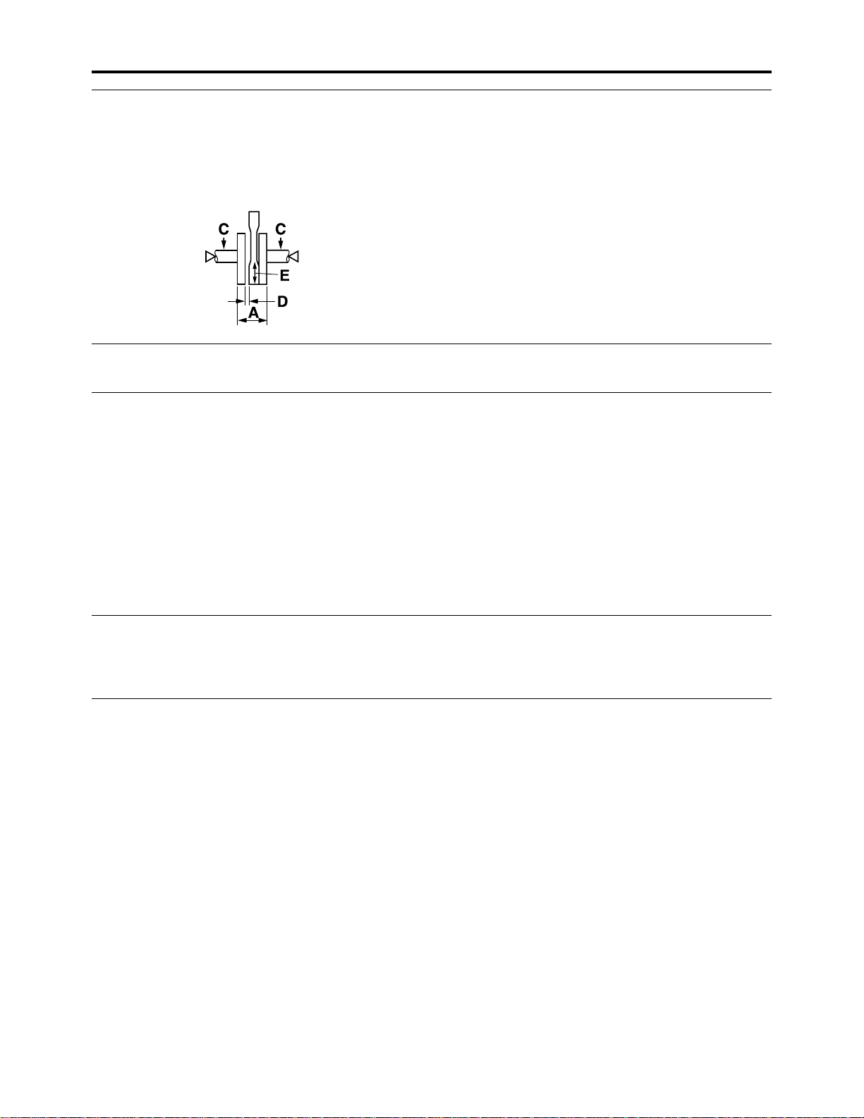
Crankshaft
Width A 69.25–69.30 mm (2.726–2.728 in)
Runout limit C 0.03 mm (0.0012 in)
Big end side clearance D 0.350–0.650 mm (0.0138–0.0256 in)
Limit 0.50 mm (0.0197 in)
Big end radial clearance E 0.010–0.025 mm (0.0004–0.0010 in)
Balancer
Balancer drive method Gear
Clutch
Friction plate thickness 2.90–3.10 mm (0.114–0.122 in)
Limit 2.80 mm (0.110 in)
Plate quantity 6 pcs
Clutch plate thickness 1.50–1.70 mm (0.059–0.067 in)
Plate quantity 5 pcs
Clutch plate warpage limit 0.20 mm (0.0079 in)
Clutch spring free length 47.80 mm (1.88 in)
Limit 46.50 mm (1.83 in)
Spring quantity 5 pcs
Clutch release method Inner push, cam push
Push rod 2 bending limit 0.10 mm (0.004 in)
Transmission
Main axle runout limit 0.06 mm (0.0024 in)
Drive axle runout limit 0.06 mm (0.0024 in)
Main axle assembly width 102.2–102.4 mm (4.02–4.03 in)
Shifting mechanism
Shift mechanism type Shift drum and guide bar
Shift fork guide bar bending limit 0.05 mm (0.002 in)
2-8
Page 28

ENGINE SPECIFICATIONS
Carburetor
ID mark 4D31 00
Main jet #133.8
Main air jet #140
Jet needle 5DH66-1
Needle jet P-0M (922)
Pilot air jet 1 #85
Pilot air jet 2 #170
Pilot outlet 0.9
Pilot jet #25
Bypass 1 0.8
Bypass 2 0.8
Bypass 3 0.8
Valve seat size 2
Starter jet 1 #55
Starter jet 2 0.5
Throttle valve size #100
Float height 13.0 mm (0.51 in)
Idling condition
Engine idling speed 1500–1600 r/min
CO% 4.0–5.0%
Intake vacuum 34.0 kPa (255 mmHg, 10.0 inHg)
Oil temperature 55.0–65.0 °C (131.0–149.0 °F)
Oil pump
Oil pump type Trochoid
Inner-rotor-to-outer-rotor-tip clearance 0.15 mm (0.0059 in)
Limit 0.23 mm (0.0091 in)
Outer-rotor-to-oil-pump-housing clearance 0.100–0.151 mm (0.0039–0.0059 in)
Limit 0.22 mm (0.0087 in)
Oil-pump-housing-to-inner-and-outer-rotor
clearance 0.04–0.09 mm (0.0016–0.0035 in)
Limit 0.16 mm (0.0063 in)
Oil pressure (hot) 3.0 kPa/1550 r/min (0.03 kgf/cm
0.4 psi/1550 r/min)
Pressure check location Cylinder head
2
/1550 r/min,
2-9
Page 29

CHASSIS SPECIFICATIONS
EAS29130
CHASSIS SPECIFICATIONS
Front suspension
Shock absorber travel 90.7 mm (3.57 in) (4D3D)
88.4 mm (3.48 in) (4D3H, 4D3M)
Spring free length 248.5 mm (9.78 in) (4D3D)
Spring rate K1 23.00 N/mm (2.35 kgf/mm, 131.33 lbf/in)
Spring stroke K1 0.0–90.7 mm (0.00–3.57 in) (4D3D)
Optional spring available No
Rear suspension
Rear shock absorber assembly travel 87.0 mm (3.43 in)
Spring free length 240.5 mm (9.47 in)
Installed length 230.0 mm (9.06 in) (4D3D)
Spring rate K1 54.00 N/mm (5.51 kgf/mm, 308.34 lbf/in)
Spring stroke K1 0.0–87.0 mm (0.00–3.43 in)
Optional spring available No
Enclosed gas/air pressure (STD) 2500 kPa (25.0 kgf/cm
Rear axle
Rear axle runout limit 1.5 mm (0.06 in)
Swingarm
Swingarm end free play limit (radial) 1.0 mm (0.04 in)
Swingarm end free play limit (axial) 1.0 mm (0.04 in)
Front wheel
Wheel type Panel wheel
Rim size 10 × 5.5AT
Rim material Aluminum
Radial wheel runout limit 2.0 mm (0.08 in)
Lateral wheel runout limit 2.0 mm (0.08 in)
Rear wheel
Wheel type Panel wheel
Rim size 9 × 8.5AT
Rim material Aluminum
Radial wheel runout limit 2.0 mm (0.08 in)
Lateral wheel runout limit 2.0 mm (0.08 in)
Drive chain
Type/manufacturer 520V/DAIDO
Link quantity 91
Drive chain slack 45.0–55.0 mm (1.77–2.17 in)
15-link length limit 239.3 mm (9.42 in)
224.6 mm (8.84 in) (4D3H, 4D3M)
0.0–88.4 mm (0.00–3.48 in) (4D3H, 4D3M)
228.0 mm (8.98 in) (4D3H, 4D3M)
2
, 355.6 psi) (4D3D)
1150–1250 kPa (11.5–12.5 kgf/cm
2
1813 psi) (4D3H, 4D3M)
, 166.8–
2-10
Page 30

CHASSIS SPECIFICATIONS
Front brake
Type Dual disc brake
Disc outside diameter × thickness 161.0 × 3.5 mm (6.34 × 0.14 in)
Brake disc thickness limit 3.0 mm (0.12 in)
Brake disc deflection limit 0.15 mm (0.006 in)
Brake pad lining thickness (inner) 4.4 mm (0.17 in)
Limit 1.5 mm (0.06 in)
Brake pad lining thickness (outer) 4.4 mm (0.17 in)
Limit 1.5 mm (0.06 in)
Master cylinder inside diameter 12.7 mm (0.50 in)
Caliper cylinder inside diameter 27.00 mm (1.06 in)
Recommended fluid DOT 4
Rear brake
Type Single disc brake
Disc outside diameter × thickness 200.0 × 4.0 mm (7.87 × 0.16 in)
Brake disc thickness limit 3.5 mm (0.14 in)
Brake disc deflection limit 0.15 mm (0.006 in)
Brake pad lining thickness (inner) 4.2 mm (0.17 in)
Limit 1.0 mm (0.04 in)
Brake pad lining thickness (outer) 4.2 mm (0.17 in)
Limit 1.0 mm (0.04 in)
Master cylinder inside diameter 12.7 mm (0.50 in)
Caliper cylinder inside diameter 33.96 mm (1.34 in)
Recommended fluid DOT 4
Lever and pedal
Brake lever free play 0 mm (0 in)
Brake pedal height 40.0 mm (1.57 in)
Parking brake cable and length 64.0–68.0 mm (2.52–2.68 in)
Clutch cable free play (lever end) 5.0–10.0 mm (0.20–0.39 in)
Throttle cable free play 2.0–4.0 mm (0.08–0.16 in)
Speed limiter length Less than 12 mm (0.47 in)
Shift pedal height 15.2 mm (0.60 in)
2-11
Page 31

ELECTRICAL SPECIFICATIONS
EAS29140
ELECTRICAL SPECIFICATIONS
System voltage
System voltage 12 V
Ignition system
Ignition timing (B.T.D.C.) 10.0 °/1550 r/min
Advanced timing (B.T.D.C.) 24.4 °/5000 r/min
Advancer type Digital
DC. CDI
Pickup coil resistance 248-372 Ω (R–W)
CDI unit model/manufacturer 4D3/YAMAHA
Ignition coil
Model/manufacturer 2JN/YAMAHA
Minimum ignition spark gap 6.0 mm (0.24 in)
Primary coil resistance 0.18–0.28 Ω
Secondary coil resistance 6.32–9.48 kΩ
Spark plug cap
Material Resin
Resistance 10.0 kΩ
AC magneto
Model/manufacturer F5XT/YAMAHA
Standard output 14.0 V 190 W 5000 r/min
Stator coil resistance 0.688–1.032 Ω (W–W)
Rectifier/regulator
Regulator type Semi conductor-short circuit
Model/manufacturer SH640E-11/SHINDENGEN
No load regulated voltage 14.1–14.9 V
Rectifier capacity 14.0 A
Withstand voltage 200.0 V
Battery
Specific gravity 1.31
Electric starting system
System type Constant mesh
Starter motor
Model/manufacturer 4D3/YAMAHA
Power output 0.40 kW
Armature coil resistance 0.013–0.015 Ω
Brush overall length 10.0 mm (0.39 in)
Limit 3.50 mm (0.14 in)
Brush spring force 5.52–8.28 N (563–844 gf, 19.87–29.80 ozf)
Commutator diameter 22.0 mm (0.87 in)
Limit 21.0 mm (0.83 in)
Mica undercut (depth) 1.50 mm (0.06 in)
Starter relay
Model/manufacturer A4616-051/JIDECO
Amperage 180.0 A
Coil resistance 4.18–4.62 Ω
2-12
Page 32

ELECTRICAL SPECIFICATIONS
Headlight relay
Model/manufacturer G8HN-1C4T-DJ-Y52/OMRON
Coil resistance 94.5–115.5 Ω
Circuit breaker
Circuit breaker type Fuse
Fuse
Fuse 15.0 A
Reserve 15.0 A
2-13
Page 33

EAS20320
TIGHTENING TORQUES
EAS20330
GENERAL TIGHTENING TORQUE SPECIFICATIONS
This chart specifies tightening torques for standard fasteners with a standard ISO thread
pitch. Tightening torque specifications for special components or assemblies are provided
for each chapter of this manual. To avoid
warpage, tighten multi-fastener assemblies in
a crisscross pattern and progressive stages
until the specified tightening torque is reached.
Unless otherwise specified, tightening torque
specifications require clean, dry threads. Components should be at room temperature.
TIGHTENING TORQUES
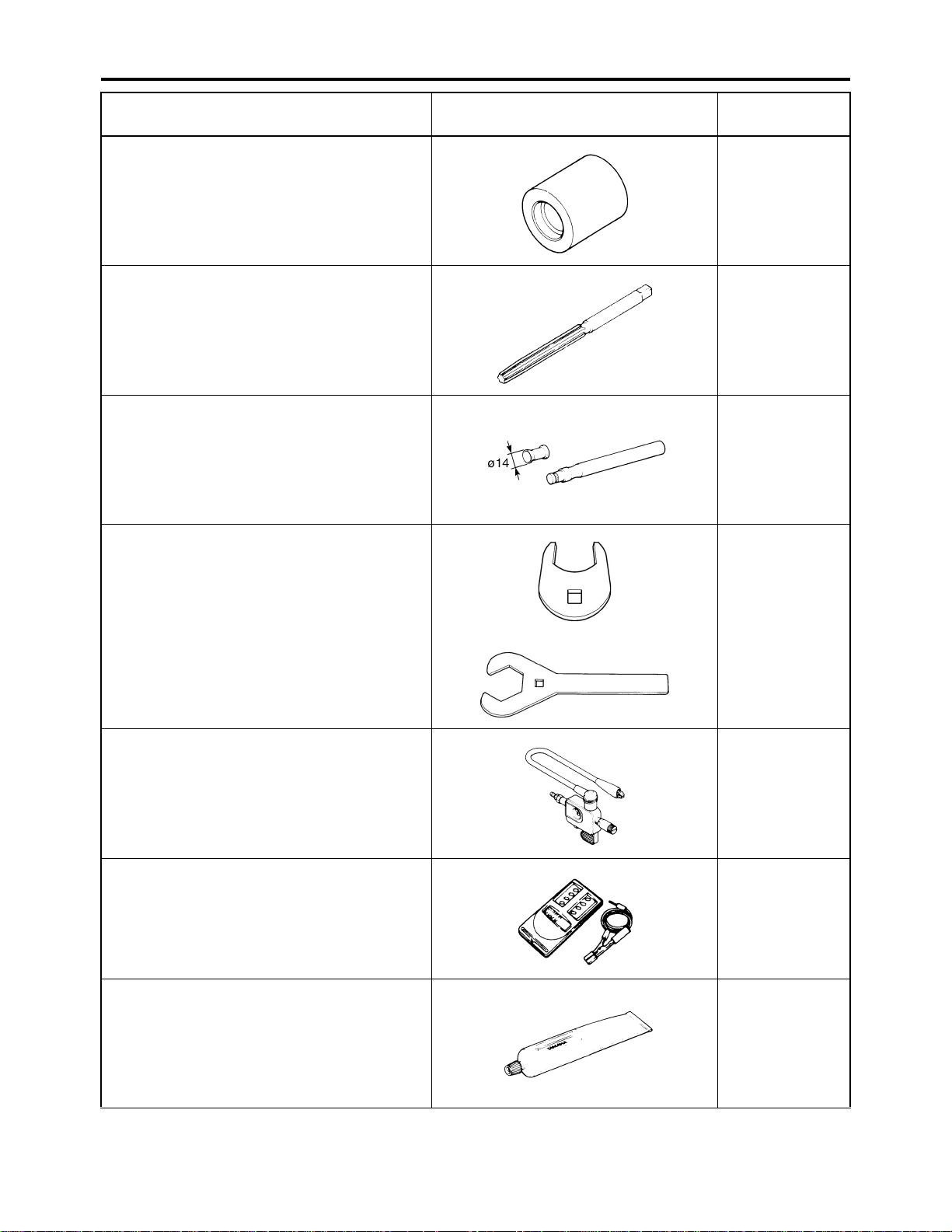
A. Distance between flats
B. Outside thread diameter
General tightening
A (nut) B (bolt)
10 mm 6 mm 6 0.6 4.3
12 mm 8 mm 15 1.5 11
14 mm 10 mm 30 3.0 22
17 mm 12 mm 55 5.5 40
19 mm 14 mm 85 8.5 61
22 mm 16 mm 130 13.0 94
torques
Nm m·kg ft·lb
2-14
Page 34

EAS20340
ENGINE TIGHTENING TORQUES
TIGHTENING TORQUES
Item
Thread
size
Q’ty Tightening torque Remarks
Cylinder head bolt (upper) M8 4 24 Nm (2.4 m·kg, 18 ft·lb)
Cylinder head bolt M8 2 20 Nm (2.0 m·kg, 15 ft·lb)
Camshaft lock plate bolt M6 2 8 Nm (0.8 m·kg, 5.9 ft·lb)
Cylinder head side cover bolt (1 and 2) M55 2 18 Nm (1.8 m·kg, 13 ft·lb)
Cylinder head side cover bolt 3 M6 2 10 Nm (1.0 m·kg, 7.4 ft·lb)
Cylinder head breather plate bolt M6 2 10 Nm (1.0 m·kg, 7.4 ft·lb)
Spark plug M12 1 18 Nm (1.8 m·kg, 13 ft·lb)
Cylinder head stud bolt M8 2 15 Nm (1.5 m·kg, 11 ft·lb)
Oil gallery bolt M6 1 6 Nm (0.6 m·kg, 4.4 ft·lb)
Carburetor joint bolt M6 2 10 Nm (1.0 m·kg, 7.4 ft·lb)
Plate 2 bolt M6 2 12 Nm (1.2 m·kg, 8.9 ft·lb)
Cylinder bolt M6 2 10 Nm (1.0 m·kg, 7.4 ft·lb)
Pickup coil rotor bolt M10 1 60 Nm (6.0 m·kg, 44 ft·lb)
Balancer weight gear nut M12 1 55 Nm (5.5 m·kg, 41 ft·lb)
Valve clearance adjusting locknut M6 2 14 Nm (1.4 m·kg, 10 ft·lb)
Camshaft sprocket bolt M10 1 60 Nm (6.0 m·kg, 44 ft·lb)
Timing chain tensioner bolt M6 2 10 Nm (1.0 m·kg, 7.4 ft·lb)
Timing chain tensioner cap bolt M6 1 8 Nm (0.8 m·kg, 5.9 ft·lb)
Timing chain guide bolt (intake side) M6 2 8 Nm (0.8 m·kg, 5.9 ft·lb)
Oil filter element cover bolt M6 3 10 Nm (1.0 m·kg, 7.4 ft·lb)
Oil delivery pipe and right crankcase
cover union bolt
M10 1 20 Nm (2.0 m·kg, 15 ft·lb)
Oil delivery pipe and cylinder union bolt M8 1 17 Nm (1.7 m·kg, 13 ft·lb)
Oil pump assembly screw M6 3 6 Nm (0.6 m·kg, 4.4 ft·lb)
Carburetor joint clamp screw (front) M4 2 4 Nm (0.4 m·kg, 3.0 ft·lb)
Carburetor joint clamp screw (rear) M4 1 4 Nm (0.4 m·kg, 3.0 ft·lb)
Exhaust pipe nut M8 2 18 Nm (1.8 m·kg, 13 ft·lb)
Muffler joint bolt M8 1 20 Nm (2.0 m·kg, 15 ft·lb)
Muffler bolt M8 2 34 Nm (3.4 m·kg, 25 ft·lb)
Right crankcase cover bolt M6 13 10 Nm (1.0 m·kg, 7.4 ft·lb)
Left crankcase cover bolt M6 9 10 Nm (1.0 m·kg, 7.4 ft·lb)
Crankcase bolt M6 12 10 Nm (1.0 m·kg, 7.4 ft·lb)
Crankcase nut M10 1 40 Nm (4.0 m·kg, 30 ft·lb)
AC magneto lead clamp bolt M5 1 7 Nm (0.7 m·kg, 5.2 ft·lb)
Engine oil drain bolt M12 1 20 Nm (2.0 m·kg, 15 ft·lb)
Ground lead, clutch cable holder bolt M6 1 10 Nm (1.0 m·kg, 7.4 ft·lb)
Neutral switch lead clamp bolt M6 1 10 Nm (1.0 m·kg, 7.4 ft·lb)
Starter idle gear cover bolt M6 3 10 Nm (1.0 m·kg, 7.4 ft·lb)
Starter clutch bolt M8 3 30 Nm (3.0 m·kg, 22 ft·lb)
See TIP
E
M
LT
LT
Use a lock
washer.
LT
LT
LT
LT
2-15
Page 35

TIGHTENING TORQUES
Item
Primary drive gear nut M16 1 80 Nm (8.0 m·kg, 59 ft·lb)
Clutch boss nut M16 1 75 Nm (7.5 m·kg, 55 ft·lb)
Thread
size
Q’ty Tightening torque Remarks
Use a lock
washer.
Use a lock
washer.
Clutch spring screw M6 5 8 Nm (0.8 m·kg, 5.9 ft·lb)
Push lever adjusting screw locknut M6 1 8 Nm (0.8 m·kg, 5.9 ft·lb)
Push lever shaft bolt M8 1 12 Nm (1.2 m·kg, 8.9 ft·lb)
Chain case cover bolt M10 2 10 Nm (1.0 m·kg, 7.4 ft·lb)
Drive sprocket n ut M18 1 110 Nm (11.0 m·kg, 81 f t·lb)
Stopper lever bolt M6 1 10 Nm (1.0 m·kg, 7.4 ft·lb)
Use a lock
washer.
LT
Shift pedal bolt M6 1 10 Nm (1.0 m·kg, 7.4 ft·lb)
Neutral switch M10 1 20 Nm (2.0 m·kg, 15 ft·lb)
Starter motor bolt M6 2 10 Nm (1.0 m·kg, 7.4 ft·lb)
Stator coil bolt M6 3 10 Nm (1.0 m·kg, 7.4 ft·lb)
Pickup coil bolt M6 2 10 Nm (1.0 m·kg, 7.4 ft·lb)
TIP
LT
LT
Apply oil to the bearing surface of (upper) cylinder head bolt. Further, apply molybdenum disulfide
grease to thread part.
2-16
Page 36

EAS20350
CHASSIS TIGHTENING TORQUES
TIGHTENING TORQUES
Item
Engine upper stay and frame M8 2 33 Nm (3.3 m·kg, 24 ft·lb)
Engine upper stay and engine M10 1 66 Nm (6.6 m·kg, 49 ft·lb)
Engine lower stay and frame M8 4 33 Nm (3.3 m·kg, 24 ft·lb)
Engine lower stay and engine M10 1 40 Nm (4.0 m·kg, 30 ft·lb)
Engine and frame M10 2 66 Nm (6.6 m·kg, 49 ft·lb)
Drive chain guide roller and frame M8 1 23 Nm (2.3 m·kg, 17 ft·lb)
Engine skid plate and frame M6 4 7 Nm (0.7 m·kg, 5.2 ft·lb)
Front fender stay and front fender M6 4 7 Nm (0.7 m·kg, 5.2 ft·lb)
Front fender stay and frame M6 6 7 Nm (0.7 m·kg, 5.2 ft·lb)
Side cover and frame M6 1 7 Nm (0.7 m·kg, 5.2 ft·lb)
Air filter case and frame M6 2 7 Nm (0.7 m·kg, 5.2 ft·lb)
Rear fender, air filter case and frame M6 3 7 Nm (0.7 m·kg, 5.2 ft·lb)
Rear fender and frame M6 2 7 Nm (0.7 m·kg, 5.2 ft·lb)
Foot protector stay and frame M8 2 17 Nm (1.7 m·kg, 13 ft·lb)
Foot protector stay and foot protector M6 2 7 Nm (0.7 m·kg, 5.2 ft·lb)
Foot protector stay and foot protector M5 6 6 Nm (0.6 m·kg, 4.4 ft·lb)
Foot protector stay and footrest M8 4 17 Nm (1.7 m·kg, 13 ft·lb)
Rear fender and rear fender stay M6 2 7 Nm (0.7 m·kg, 5.2 ft·lb)
Swingarm pivot shaft and frame M14 1 100 Nm (10.0 m·kg, 74 f t·lb)
Rear shock absorber and frame M12 1 55 Nm (5.5 m·kg, 41 ft·lb)
Rear shock absorber and swingarm M12 1 55 Nm (5.5 m·kg, 41 ft·lb)
Rear axle pinch bolt M8 4 21 Nm (2.1 m·kg, 15 ft·lb)
Swingarm and swingarm skid plate M6 4 9 Nm (0.9 m·kg, 6.6 ft·lb)
Swingarm and drive chain guide 1 M6 1 7 Nm (0.7 m·kg, 5.2 ft·lb)
Upper front arm and frame M10 2 45 Nm (4.5 m·kg, 33 ft·lb)
Lower front arm and frame M10 4 45 Nm (4.5 m·kg, 33 ft·lb)
Front shock absorber and frame M10 2 48 Nm (4.8 m·kg, 35 ft·lb)
Front shock absorber and lower front arm M10 2 48 Nm (4.8 m·kg, 35 ft·lb)
Steering knuckle and front arm (upper
and lower)
Steering stem bushing and frame M8 2 23 Nm (2.3 m·kg, 17 ft·lb)
Steering stem and frame M10 1 35 Nm (3.5 m·kg, 26 ft·lb)
Steering stem and handlebar holder M8 4 20 Nm (2.0 m·kg, 15 ft·lb)
Steering knuckle and tie-rod ball joint M10 2 25 Nm (2.5 m·kg, 18 ft·lb)
Steering stem and tie-rod ball joint M10 2 25 Nm (2.5 m·kg, 18 ft·lb)
Locknut (tie-rod end) M10 4 15 Nm (1.5 m·kg, 11 ft·lb)
Fuel tank and frame M6 4 7 Nm (0.7 m·kg, 5.2 ft·lb)
Fuel tank and fuel cock M6 2 4 Nm (0.4 m·kg, 3.0 ft·lb)
Front wheel and front wheel hub M10 8 45 Nm (4.5 m·kg, 33 ft·lb)
Steering knuckle and front wheel hub M14 2 70 Nm (7.0 m·kg, 52 ft·lb)
Steering knuckle and front brake caliper
bracket
Brake disc guard (inner) and steering
knuckle
Thread
size
M10 4 25 Nm (2.5 m·kg, 18 ft·lb)
M8 4 28 Nm (2.8 m·kg, 21 ft·lb)
M6 4 7 Nm (0.7 m·kg, 5.2 ft·lb)
Q’ty Tightening torque Remarks
Use a lock
washer.
2-17
Page 37

TIGHTENING TORQUES
Item
Thread
size
Q’ty Tightening torque Remarks
Front brake disc and front wheel hub M8 8 28 Nm (2.8 m·kg, 21 ft·lb)
Rear wheel and rear wheel hub M10 8 45 Nm (4.5 m·kg, 33 ft·lb)
Rear axle and rear wheel hub M14 2 120 Nm (12.0 m·kg, 89 ft·lb)
Rear axle ring nut M33 1
140 Nm (14.0 m·kg, 103
ft·lb)
Rear axle ring nut set bolt M6 2 7 Nm (0.7 m·kg, 5.2 ft·lb)
Rear brake caliper and brake caliper
bracket
M8 2 34 Nm (3.4 m·kg, 25 ft·lb)
Rear brake disc and brake disc bracket M8 4 28 Nm (2.8 m·kg, 21 ft·lb)
Adjusting bolt locknut (parking brake) M8 1 15 Nm (1.5 m·kg, 11 ft·lb)
Driven sprocket and sprocket bracket M10 4 55 Nm (5.5 m·kg, 41 ft·lb)
Front brake pipe flare nut M10 2 19 Nm (1.9 m·kg, 14 ft·lb)
Front brake master cylinder and brake
hose
M10 1 27 Nm (2.7 m·kg, 20 ft·lb)
Front brake caliper and brake hose M10 2 27 Nm (2.7 m·kg, 20 ft·lb)
Front brake pad retaining bolt M10 1 17 Nm (1.7 m·kg, 13 ft·lb)
Front brake caliper bleed screw M8 2 6 Nm (0.6 m·kg, 4.4 ft·lb)
Front brake hose clamp bolt M6 2 7 Nm (0.7 m·kg, 5.2 ft·lb)
Front brake hose joint and frame M6 1 10 Nm (1.0 m·kg, 7.4 ft·lb)
Front brake master cylinder and handle-
bar
Front brake master cylinder and brake
lever
M6 2 7 Nm (0.7 m·kg, 5.2 ft·lb)
M6 1 6 Nm (0.6 m·kg, 4.4 ft·lb)
Clutch lever holder and handlebar M5 2 4 Nm (0.4 m·kg, 3.0 ft·lb)
Parking brake lever assembly and clutch
lever holder
M6 2 7 Nm (0.7 m·kg, 5.2 ft·lb)
Throttle lever assembly and handlebar M5 2 4 Nm (0.4 m·kg, 3.0 ft·lb)
Footrest and frame M10 4 73 Nm (7.3 m·kg, 54 ft·lb)
Rear brake master cylinder and frame M8 2 20 Nm (2.0 m·kg, 15 ft·lb)
Rear brake master cylinder and brake
hose
M10 1 31 Nm (3.1 m·kg, 23 ft·lb)
Rear brake caliper and brake hose M10 1 31 Nm (3.1 m·kg, 23 ft·lb)
Rear brake reservoir and frame M6 1 7 Nm (0.7 m·kg, 5.2 ft·lb)
Rear brake caliper retaining bolt M8 1 17 Nm (1.7 m·kg, 13 ft·lb)
Parking brake case and caliper M8 2 22 Nm (2.2 m·kg, 16 ft·lb)
Rear brake pad retaining bolt M8 2 17 Nm (1.7 m·kg, 13 ft·lb)
Rear brake caliper bleed screw M8 1 6 Nm (0.6 m·kg, 4.4 ft·lb)
Front bumper and frame M8 4 31 Nm (3.1 m·kg, 23 ft·lb)
Rear carrier bar and frame M8 4 34 Nm (3.4 m·kg, 25 ft·lb)
Headlight and front fender stay M6 2 7 Nm (0.7 m·kg, 5.2 ft·lb)
Tail/brake light bracket and air filter case M6 2 4 Nm (0.4 m·kg, 3.0 ft·lb)
Rectifier/regulator and front fender stay M6 2 7 Nm (0.7 m·kg, 5.2 ft·lb)
Main switch and front fender M22 1 1 Nm (0.1 m·kg, 3.0 ft·lb)
Ignition coil and frame M6 2 7 Nm (0.7 m·kg, 5.2 ft·lb)
LT
LT
LT
LT
LT
Use a lock
washer.
2-18
Page 38

LUBRICATION POINTS AND LUBRICANT TYPES
EAS20360
LUBRICATION POINTS AND LUBRICANT TYPES
EAS20370
ENGINE
Lubrication point Lubricant
Oil seal lips
O-rings
Bearings
Cylinder head bolts (bearing surface of bolts)
Cylinder head bolts (thread part)
Cylinder body surface
Crankshaft journals
Connecting rod small end and big end
Piston pin
Piston surface
Boss periphery
Valve stems (intake and exhaust)
Valve stem ends (intake and exhaust)
Rocker arm shafts (intake and exhaust)
Camshaft lobes
Rocker arms inner surface
Oil pump rotors (inner and outer) and oil pump housing and shaft
Starter idler gear 1
Starter idler gear 2
Starter wheel gear
Push rods
Clutch housing (primary driven gear)
Push lever shaft
Push rod ball
Transmission gears (inside and end)
Transmission gears (fork ditch)
Shift fork guide bar
Shift drum
Shift shafts
Crankcase mating surfaces
AC magneto lead grommet (AC magneto cover)
LS
LS
E
E
M
E
E
E
E
E
E
M
M
E
M
M
E
E
E
E
LS
E
E
LS
M
E
E
E
E
Yamaha bond
No.1215 (Three bond
No.1215®)
Yamaha bond
No.1215 (Three bond
No.1215®)
2-19
Page 39

LUBRICATION POINTS AND LUBRICANT TYPES
2-20
Page 40

LUBRICATION SYSTEM CHART AND DIAGRAMS
EAS20390
LUBRICATION SYSTEM CHART AND DIAGRAMS
EAS20400
ENGINE OIL LUBRICATION CHART
2-21
Page 41

1. Oil pan
2. Oil strainer
3. Oil pump
4. Oil cooler
5. Oil filter element
6. Cylinder head
7. Camshaft
8. Pin with hole
9. Crankshaft
10.Drive axle
11.Main axle
LUBRICATION SYSTEM CHART AND DIAGRAMS
2-22
Page 42

LUBRICATION SYSTEM CHART AND DIAGRAMS
EAS20410
LUBRICATION DIAGRAMS
2-23
Page 43

1. Camshaft
2. Oil filter element
3. Oil pump
4. Oil strainer
LUBRICATION SYSTEM CHART AND DIAGRAMS
2-24
Page 44

LUBRICATION SYSTEM CHART AND DIAGRAMS
2-25
Page 45

1. Camshaft
2. Drive axle
3. Main axle
4. Push lever shaft
5. Oil pump assembly
6. Oil strainer
7. Crankshaft assembly
8. Oil filter element
LUBRICATION SYSTEM CHART AND DIAGRAMS
2-26
Page 46

LUBRICATION SYSTEM CHART AND DIAGRAMS
2-27
Page 47

1. Oil cooler
2. Oil hose 1
3. Oil hose 2
LUBRICATION SYSTEM CHART AND DIAGRAMS
2-28
Page 48

EAS20430
CABLE ROUTING
CABLE ROUTING
2-29
Page 49

1. Clutch switch lead
2. Clutch cable
3. Front brake hose 1
4. Front brake light switch lead
5. Throttle cable
6. Plastic band
7. Parking brake cable
8. Handlebar switch lead
A. Route the clutch cable and parking br ake
cable through the guide of the handlebar
protector.
B. Route the clutch cable in front of the park-
ing brake cable.
C. Route the front brake hose and t hrottle
cable through the guide of the handlebar
protector.
D. Clamp the front brake light switch lead at
the bends of handlebar.
E. Route the throttle cable under the front
brake hose.
F. Clamp the clutch switch lead and handle-
bar switch lead at the bends of handlebar.
CABLE ROUTING
2-30
Page 50

CABLE ROUTING
2-31
Page 51

CABLE ROUTING
1. Indicator light lead
2. Main switch lead
3. Coupler joint
4. Front brake hose 2
5. Oil cooler hose 1, 2
6. Exhaust pipe
7. Engine bracket
8. Parking brake cable
9. Rear brake light switch lead
10.Battery negative lead
11.Carburetor warmer lead
12.Air vent hose
13.3 way connector
14.Breather hose
15.Front brake light switch lead
16.Throttle cable
17.Front brake hose 1
18.Clutch cable
19.Main harness
20.Clamp
21.Frame complete
22.Rear brake reservoir hose
23.Carburetor overflow hose
24.Neutral switch lead
25.Rear brake reservoir
O. When installing the brake pipe, place the
marking on top and tighten the above flare
nut first.
P. Route the rear brake light switch lead
under the bracket.
Q. Route the rear brake light switch lead, ne u-
tral switch lead, air vent hose, carburetor
overflow hose and parking brake cab le
through the bracket.
R. Route the rear brake light switch lead
between the bracket and rear brake reservoir.
S. Route the neutral switch lead and rear
brake light switch lead as shown in the
illustration.
A. To the front panel
B. To the front fender
C. To the right headlight
D. Make sure to route the oil cooler hoses 1
and 2 through the guide wire.
E. Install the front brake hose 2, making sure
to face the white paint mark forward.
F. Route the oil cooler hose 1 and 2 be tween
the exhaust pipe and the engine bracket.
G. Route the battery negative lead behind the
clutch cable holder.
H. Route the air vent hose through the
bracket.
I. Route the breather hose under the 3 way
connector and outside of the throttle cable
cover.
J. Face the white paint mark on the breather
hose upward. F ace the tab of the clip to the
left.
K. To the handlebar
L. Route the throttle cable under the cross
pipe and left of the steering column as
shown in the illustration.
M. Route the parking brake cable and the
clutch cable under t he cr oss pip e an d right
of the steering column as shown in the
illustration.
N. When installing the brake pipe, make sure
to have more than 10 mm (0.39 in) clear-
ance from frame complete and steeri ng
stem after tightening the flare nut.
2-32
Page 52

CABLE ROUTING
2-33
Page 53

1. Rear brake reservoir
2. Rear brake light switch
3. Clip
4. Rear brake reservoir hose
5. Rear brake master cylinder
6. Parking brake cable
7. Rear brake hose
8. Rear brake caliper
A. Make sure that the end of the clip is facing
downward.
B. Set the rear brake reservoir hose with the
positioning yellow paint mark pointing
down.
C. Install the rear brake hose in the dir ection
shown in the illustration.
D. Insert the rear brake hose until it contacts
the projection.
E. Make sure that the end of the clip is facing
outward.
F. Install the rear brake reservoir hose, mak-
ing sure to face the white paint mark out-
ward.
G. Insert the rear brake reservoir hose until it
contacts the projection.
H. When installing the rear brak e hose, make
sure that the metal part on the rear brake
Inlet hose is touching the stopper of the
rear caliper.
CABLE ROUTING
2-34
Page 54

CABLE ROUTING
2-35
Page 55

4D3D
1. Clutch switch lead
2. Handlebar switch lead
3. Bolt
4. Hexagonal head bolt
5. Main harness
6. Air vent hose
7. Clamp
8. Battery negative lead
9. AC magneto lead
10.Carburetor overflow hose
11.Neutral switch lead
12.Starter motor lead
13.Ignition coil spark plug lead
14.Ignition coil
15.Drain hose
16.Frame complete
17.Damper plate
18.Seat pad
19.Rear brake light switch lead
20.Carburetor warmer lead
21.Side cover
22.Breather hose
23.Air filter joint
24.Air filter case
CABLE ROUTING
A. To the left headlight
B. To the front fender
C. Route t he wire harness abov e the guide f or
the damper plate.
D. Fix point for wire harness
E. Clamp near the hook of the air filter.
F. Clamp near the edge of the air filter case.
G. Route the drain hose in front of the left oil
cooler hose.
H. Clamp on top of the frame bracket.
I. Route the clamp through the damper plate
hole.
J. Route the carburetor overflow hose as
shown in the illustration.
K. Fasten the clamp with the engine.
L. Route the clamp through the frame
bracket.
M. Route the leads on the upper inside of the
side cover.
N. Place the coupler s on the inside of th e side
cover.
2-36
Page 56

CABLE ROUTING
2-37
Page 57

4D3H/4D3M
1. Clutch switch lead
2. Handlebar switch lead
3. Bolt
4. Hexagonal head bolt
5. Main harness
6. Air vent hose
7. Clamp
8. Battery negative lead
9. AC magneto lead
10.Carburetor overflow hose
11.Neutral switch lead
12.Starter motor lead
13.Ignition coil spark plug lead
14.Ignition coil
15.Drain hose
16.Frame complete
17.Damper plate
18.Seat pad
19.Rear brake light switch lead
20.Carburetor warmer lead
21.Side cover
22.Breather hose
23.Air filter joint
24.Air filter case
25.Rear shock absorber sub-tank hose
CABLE ROUTING
A. To the left headlight
B. To the front fender
C. Route t he wire harness abov e the guide f or
the damper plate.
D. Fix point for wire harness
E. Clamp near the hook of the air filter.
F. Clamp near the edge of the air filter case.
G. Route the drain hose in front of the left oil
cooler hose.
H. Clamp on top of the frame bracket.
I. Route the clamp through the damper plate
hole.
J. Route the carburetor overflow hose as
shown in the illustration.
K. Fasten the clamp with the engine.
L. Route the clamp through the frame
bracket.
M. Route the leads on the upper inside of the
side cover.
N. Place the coupler s on the inside of th e side
cover.
O. Route the rear shock absorber sub-tank
hose under the side cover.
2-38
Page 58

CABLE ROUTING
2-39
Page 59

1. Indicator light
2. Coupler joint
3. Main switch lead
4. Main switch
5. Front brake light switch lead
6. Throttle cable
7. Air vent hose
8. Clutch switch lead
9. Handlebar switch lead
10.Parking brake cable
11.Clutch cable
12.Flange bolt
13.Headlight lead
14.Indicator light lead
15.Rear brake reservoir
16.Rear brake light switch lead
17.Battery negative lead
18.Carburetor warmer lead
19.Starter motor lead
20.Rectifier/regulator
21.Main harness
22.Frame complete
23.Clamp
CABLE ROUTING
A. Install the indicator light as shown in the
illustration.
B. Place the coupler joint above the front
fender.
C. Connect the main switch lead on top of the
front fender. Route both leads from the
front.
D. Route the front brake light switch lead and
throttle cable through the guide.
E. Insert the air vent hose into the front
fender.
F. Route the clutch switch lead and handlebar
switch lead on the box shaped part.
G. Connect the clutch switch lead and handle-
bar switch lead on top of the front fender.
Route the wire harness from the front.
H. Route t he cables and leads through the
guide of the front fender. Route the leads
behind the clutch and parking brake cable.
I. Route the headlight lead under the frame.
J. To the front fender
K. To the front panel
L. To the handlebar
M. Route the air vent hose through the
bracket.
N. Route t he battery negativ e lead behind th e
clutch cable holder.
O. Fix point for wire harness
2-40
Page 60

CABLE ROUTING
2-41
Page 61

1. Battery
2. CDI unit
3. Band
4. Starter relay lead
5. Starter relay
6. Taillight lead
7. Battery negative lead
8. AC magneto coupler
9. Starter motor lead
10.Headlight relay
11.Neutral relay
12.Damper
13.CDI unit lead
14.Relay lead
A. Route the starter relay lead under the
starter motor lead.
B. After connecting the battery negative lead,
push the sag in the box.
C. After connecting the wire harness and
each electric part, the length between the
air filter and AC magneto coupler should
be 185 mm (7.28 in) on straight line.
D . Clamp the taillight lead.
E. Do not clamp.
F. Set the insulator lock on the wire harness
behind the fixed point.
G. Insert the starter relay all the way into the
rib on the air filter side.
H. There is no particular order in placing each
lead.
I. Insert each relay all the way into the rib on
the air filter side.
CABLE ROUTING
2-42
Page 62

CABLE ROUTING
2-43
Page 63

PERIODIC CHECKS AND ADJUSTMENTS
PERIODIC MAINTENANCE .........................................................................3-1
INTRODUCTION....................................................................................3-1
PERIODIC MAINTENANCE CHART FOR THE EMISSION
CONTROL SYSTEM...............................................................................3-1
GENERAL MAINTENANCE AND LUBRICATION CHART.....................3-2
ENGINE.........................................................................................................3-4
ADJUSTING THE VALVE CLEARANCE................................................3-4
ADJUSTING THE ENGINE IDLING SPEED ..........................................3-5
ADJUSTING THE THROTTLE CABLE FREE PLAY ..............................3-6
ADJUSTING THE SPEED LIMITER.......................................................3-7
CHECKING THE SPARK PLUG.............................................................3-7
CHECKING THE IGNITION TIMING......................................................3-8
MEASURING THE COMPRESSION PRESSURE.................................3-8
CHECKING THE ENGINE OIL LEVEL...................................................3-9
CHANGING THE ENGINE OIL.............................................................3-10
ADJUSTING THE CLUTCH CABLE FREE PLAY ................................3-12
CLEANING THE AIR FILTER ELEMENT .............................................3-12
CHECKING THE CARBURETOR JOINT AND INTAKE MANIFOLD....3-13
CHECKING THE FUEL LINE ...............................................................3-14
CHECKING THE CYLINDER HEAD BREATHER HOSE.....................3-14
CHECKING THE EXHAUST SYSTEM.................................................3-14
CLEANING THE SPARK ARRESTER..................................................3-14
3
CHASSIS ....................................................................................................3-16
ADJUSTING THE FRONT DISC BRAKE.............................................3-16
ADJUSTING THE BRAKE PEDAL .......................................................3-16
CHECKING THE BRAKE FLUID LEVEL..............................................3-17
CHECKING THE FRONT BRAKE PADS..............................................3-18
CHECKING THE REAR BRAKE PADS................................................3-18
CHECKING THE FRONT BRAKE HOSES...........................................3-18
CHECKING THE REAR BRAKE HOSE ...............................................3-18
ADJUSTING THE PARKING BRAKE ...................................................3-19
ADJUSTING THE REAR BRAKE LIGHT SWITCH ..............................3-19
BLEEDING THE HYDRAULIC BRAKE SYSTEM.................................3-20
ADJUSTING THE SHIFT PEDAL.........................................................3-21
ADJUSTING THE DRIVE CHAIN SLACK ............................................3-21
LUBRICATING THE DRIVE CHAIN......................................................3-22
CHECKING THE STEERING SYSTEM ...............................................3-22
ADJUSTING THE TOE-IN....................................................................3-23
CHECKING THE FRONT SHOCK ABSORBER ASSEMBLIES...........3-24
ADJUSTING THE FRONT SHOCK ABSORBER ASSEMBLIES
(for 4D3D).............................................................................................3-24
ADJUSTING THE FRONT SHOCK ABSORBER ASSEMBLIES
(for 4D3H, 4D3M)..................................................................................3-25
CHECKING THE REAR SHOCK ABSORBER ASSEMBLY.................3-27
ADJUSTING THE REAR SHOCK ABSORBER ASSEMBLY
(for 4D3D).............................................................................................3-27
Page 64

ADJUSTING THE REAR SHOCK ABSORBER ASSEMBLY
(for 4D3H, 4D3M)..................................................................................3-28
CHECKING THE TIRES.......................................................................3-29
CHECKING THE WHEELS ..................................................................3-31
CHECKING AND LUBRICATING THE CABLES..................................3-31
LUBRICATING THE LEVERS...............................................................3-31
LUBRICATING THE PEDAL.................................................................3-31
ELECTRICAL SYSTEM..............................................................................3-32
CHECKING AND CHARGING THE BATTERY.....................................3-32
CHECKING THE FUSES......................................................................3-32
REPLACING THE HEADLIGHT BULBS...............................................3-32
ADJUSTING THE HEADLIGHT BEAMS..............................................3-32
Page 65

Page 66

PERIODIC MAINTENANCE
EAS20450
PERIODIC MAINTENANCE
EAS20460
INTRODUCTION
This chapter includes all information necessary to perform recommended checks and adjustments.
If followed, these preventive maintenance procedures will ensure more reliable vehicle operation, a
longer service life and reduce the need for costly o v erhaul w ork. This inf ormation applies to v ehicles
already in service as well as to new vehicles that are being prepared f or sale. All service technicians
should be familiar with this entire chapter.
EAS4D3F011
PERIODIC MAINTENANCE CHART FOR THE EMISSION CONTROL SYSTEM
TIP
• For ATVs not equipped with an odometer or an hour meter, follow the month maintenance intervals.
• For ATVs equipped with an odometer or an hour meter, follow the km (mi) or hours maintenance
intervals. However, keep in mind that if the ATV isn’t used for a long period of time, the month
maintenance intervals should be followed.
• Items marked with an asterisk should be performed by a Yamaha dealer as they require special
tools, data and technical skills.
INITIAL EVERY
NO. ITEM
1 * Fuel line
2 Spark plug • Check condition and clean, regap, or replace if necessary. √√√√√
3*Valves • Check valve clearance and adjust if necessary. √ √√√
4*Carburetor
Crankcase
5*
breather system
6 * Exhaust system
7 Spark arrester •Clean. √√√
CHECK OR MAINTENANCE
JOB
• Check fuel hoses for cracks or other damage, and replace
if necessary.
• Check starter (choke) operation and correct if necessary.
• Check engine idling speed and adjust if necessary.
• Check breather hose for cracks or other damage, and
replace if necessary.
• Check for leakage and replace gasket(s) if necessary.
• Check for looseness and tighten all screw clamps and
joints if necessary.
Whichever
comes first
month136612
km
(mi)
hours 20 80 160 160 320
320
(200)
1300
(800)
2500
(1600)
√√√√
2500
(1600)
√√√
√√√
√√√
5000
(3200)
3-1
Page 67

PERIODIC MAINTENANCE
EAS4D3F012
GENERAL MAINTENANCE AND LUBRICATION CHART
INITIAL EVERY
NO. ITEM
1 Air filter element • Clean and replace if necessary.
2*Clutch • Check operation and adjust if necessary. √ √√√
3 * Front brake
4 * Rear brake
5 * Brake hoses
6 * Parking brake • Check operation and adjust if necessary. √√√√√
7 * Wheels • Check runout and for damage, and replace if necessary. √ √√√
8*Tires
Wheel hub bear-
9*
ings
10 * Swingarm pivots
Upper and lower
11 *
arm pivots
12 Drive chain
13 * Drive chain rollers • Check for wear and replace if necessary. √√√
14 * C hassis faste ners
Shock absorber
15 *
assemblies
Rear suspension
relay arm and con-
16 *
necting arm pivoting points
17 * Steering shaft • Lubricate with lithium-soap-based grease. √√√
18 * Steering system
19 * Engine mount
20 Engine oil
Engine oil filter
21
element
Moving parts and
22 *
cables
Throttle lever
23 *
housing and cable
Front and rear
24 *
brake switches
CHECK OR MAINTENANCE
JOB
• Check operation and correct if necessary.
• Check fluid level and ATV for fluid leakage, and correct
necessary.
• Replace brake pads. Whenever worn to the limit
• Check operation and correct if necessary.
• Check fluid level and ATV for fluid leakage, and correct
necessary.
• Replace brake pads. Whenever worn to the limit
• Check for cracks or other damage, and replace if necessary.
• Replace. Every 4 years
• Check tread depth and for damage, and replace if necessary.
• Check air pressure and balance, and correct if necessary.
• Check for looseness or damage, and replace if necessary. √ √√√
• Check operation and for excessive play, and replace bearings if necessary.
• Lubricate with lithium-soap-based grease.
• Lubricate with lithium-soap-based grease. √√√
• Check chain slack and adjust if necessary.
• Check rear wheel alignment and correct if necessary.
• Clean and lubricate.
• Make sure that all nuts, bolts, and screws are properly
tightened.
• Check operation and correct if necessary.
• Check for oil leakage and replace if necessary.
• Check operation and correct if necessary.
• Lubricate with lithium-soap-based grease.
• Check operation and repair or replace if damaged.
Check toe-in and adjust if necessary.
•
• Check for cracks or other damage, and replace if necessary.
• Change.
• Check ATV for oil leakage, and correct if necessary.
• Clean or replace if necessary. √√√
• Lubricate. √√√√
• Check operation and correct if necessary.
• Check throttle cable free play and adjust if necessary.
• Lubricate throttle lever housing and cable.
• Check operation and correct if necessary. √√√√√
Whichever
comes first
month136612
km
(mi)
hours 20 80 160 160 320
320
(200)
1300
(800)
Every 20–40 hours (more often in wet or
√√√√√
√√√√√
√ √√√
√√√√√
√√√√√
√√√√√
√ √√√
√√√√√
2500
(1600)
dusty areas)
√√√√
√√√√
2500
(1600)
√√√
√√√
√√√
5000
(3200)
3-2
Page 68

PERIODIC MAINTENANCE
INITIAL EVERY
Whichever
comes first
NO. ITEM
Lights and
25 *
switches
CHECK OR MAINTENANCE
JOB
• Check operation and correct if necessary.
• Adjust headlight beams.
TIP
• The air filter needs more frequent service if you are riding in unusually wet or dusty areas.
• Hydraulic brake service
• Regularly check and, if necessary, correct the brake fluid level.
• Every two years replace the internal components of the brake master cylinders and calipers , and
change the brake fluid.
• Replace the brake hoses every four years and if cracked or damaged.
EWA4D3F004
WARNING
Indicates a potential hazard that could result in serious injury or death.
month136612
km
(mi)
hours 20 80 160 160 320
320
(200)
1300
(800)
√√√√√
2500
(1600)
2500
(1600)
5000
(3200)
3-3
Page 69

EAS20472
ENGINE
EAS20520
ADJUSTING THE VALVE CLEARANCE
The following procedure applies to all of the
valves.
TIP
• Valve clearance adjustment should be made
on a cold engine, at room temperature.
• When the valv e clear ance is to be measured
or adjusted, the piston must be at top dead
center (TDC) on the compression stroke.
1. Remove:
• Seat
• Front fender
• Fuel tank
Refer to “GENERAL CHASSIS” on page
4-1.
Refer to “FUEL TANK” on page 6-1.
2. Remove:
• Spark plug cap
• Spark plug
• Cylinder head side cover 1 “1”
• Cylinder head side cover 2 “2”
ENGINE
Valve clearance (cold)
Intake valve
0.05–0.10 mm (0.0020–0.0039
in)
Exhaust valve
0.10–0.15 mm (0.0039–0.0059
in)
▼▼▼▼▼▼▼▼▼▼▼▼▼▼▼▼▼▼▼▼▼▼▼▼▼▼▼▼▼▼
a. Turn the crankshaft counterclockwise.
b. When the piston is at TDC on the compres-
sion stroke, align the mark “a” on the
pickup coil rotor with the stationary pointer
“b” on the left crankcase cover.
c. Align the mark “c” on the camshaft sprock et
with the stationary pointer “d” on the cylinder head.
3. Remove:
• Timing mark accessing screw “1”
• Crankshaft end accessing screw “2”
4. Measure:
• Valve clearance
Out of specification → Adjust.
d. Measure the valve clearance with a thick-
ness gauge “1”.
Out of specification → Adjust.
Thickness gauge
90890-03180
Feeler gauge set
YU-26900-9
3-4
Page 70

▲▲▲▲▲▲▲▲▲▲▲▲▲▲▲▲▲▲▲▲▲▲▲▲▲▲▲▲▲▲
5. Adjust:
• Valve clearance
▼▼▼▼▼▼▼▼▼▼▼▼▼▼▼▼▼▼▼▼▼▼▼▼▼▼▼▼▼▼
a. Loosen the locknut.
b. Insert a thickness gauge between the end
of the adjusting screw and the valve tip.
c. Turn the adjusting screw “2” in direction “a”
or “b” until the specified valve clearance is
obtained.
ENGINE
e. If the valve clearance is still out of specifi-
cation, repeat all of the valve clearance
adjustment steps until the specifie d clearance is obtained.
▲▲▲▲▲▲▲▲▲▲▲▲▲▲▲▲▲▲▲▲▲▲▲▲▲▲▲▲▲▲
6. Install:
• All removed parts
TIP
For installation, reverse the removal procedure.
EAS29150
ADJUSTING THE ENGINE IDLING SPEED
1. Start the engine and let it warm up for several minutes.
2. Attach:
• Digital tachometer
(onto the ignition coil spark plug lead)
Digital tachometer
90890-06760
YU-39951-B
Direction “a”
Valve clearance is increased.
Direction “b”
Valve clearance is decreased.
Tappet adjusting tool
90890-01311
Six piece tappet set
YM-A5970
• Hold the adjusting screw to prevent it
from moving and tighten the locknut to
specification.
3. Measure:
• Engine idling speed
Out of specification → Adjust.
Engine idling speed
1500–1600 r/min
4. Adjust:
• Engine idling speed
▼▼▼▼▼▼▼▼▼▼▼▼▼▼▼▼▼▼▼▼▼▼▼▼▼▼▼▼▼▼
a. Turn the throttle stop screw “1” in direction
“a” or “b” until the specified idling speed is
obtained.
Direction “a”
Engine idling speed is increased.
Direction “b”
Engine idling speed is decreased.
Locknut
14 Nm (1.4 m·kg, 10 ft·lb)
d. Measure the valve clearance again.
▲▲▲▲▲▲▲▲▲▲▲▲▲▲▲▲▲▲▲▲▲▲▲▲▲▲▲▲▲▲
3-5
Page 71

5. Detach:
• Digital tachometer
6. Adjust:
• Throttle cable free play
Refer to “ADJUSTING THE THROTTLE
CABLE FREE PLAY” on page 3-6.
Throttle cable free play
2.0–4.0 mm (0.08–0.16 in)
EAS20660
ADJUSTING THE THROTTLE CABLE FREE
PLAY
TIP
Prior to adjusting the throttle cable free play,
the engine idling speed should be adjusted.
1. Check:
• Throttle cable free play “a”
Out of specification → Adjust.
ENGINE
TIP
If the specified throttle cable free play cannot
be obtained on the carburetor side of the
cable, use the adjusting nut on the handlebar
side.
▲▲▲▲▲▲▲▲▲▲▲▲▲▲▲▲▲▲▲▲▲▲▲▲▲▲▲▲▲▲
▼▼▼▼▼▼▼▼▼▼▼▼▼▼▼▼▼▼▼▼▼▼▼▼▼▼▼▼▼▼
Throttle cable free play
2.0–4.0 mm (0.08–0.16 in)
2. Adjust:
• Throttle cable free play
▼▼▼▼▼▼▼▼▼▼▼▼▼▼▼▼▼▼▼▼▼▼▼▼▼▼▼▼▼▼
Carburetor side
a. Slide back the rubber cover “1”.
b. Loosen the locknut “2”.
c. Turn the adjusting nut “3” in direction “a” or
“b” until the specified throttle cable free
play is obtained.
Direction “a”
Throttle cable free play is increased.
Direction “b”
Throttle cable free play is decreased.
d. Tighten the locknut.
e. Slide the rubber cover to its original posi-
tion.
Handlebar side
a. Slide back the rubber cover “1”.
b. Loosen the locknut “2”.
c. T urn the adjusting bolt “3” in direction “a” or
“b” until the specified throttle cable free
play is obtained.
Direction “a”
Throttle cable free play is increased.
Direction “b”
Throttle cable free play is decreased.
d. Tighten the locknut.
e. Slide the rubber cover to its original posi-
tion.
EWA12930
WARNING
After adjusting the throttle cable free play,
start the engine and turn the handlebar to
the right or left to ensure that this does not
cause the engine idling speed to change.
▲▲▲▲▲▲▲▲▲▲▲▲▲▲▲▲▲▲▲▲▲▲▲▲▲▲▲▲▲▲
3-6
Page 72

ENGINE
EAS29170
ADJUSTING THE SPEED LIMITER
The speed limiter keeps the carburetor throttle
from becoming fully-opened even when the
throttle lever is applied to the maximum position. Screwing in the adjusting screw stops the
engine speed from increasing.
1. Measure:
• Speed limiter length “a”
Out of specification → Adjust.
Speed limiter length
Less than 12 mm (0.47 in)
2. Adjust:
• Speed limiter length
▼▼▼▼▼▼▼▼▼▼▼▼▼▼▼▼▼▼▼▼▼▼▼▼▼▼▼▼▼▼
a. Loosen the locknut “1”.
b. Turn the adjusting screw “2” in or out until
the specified speed limiter length is
obtained.
Direction “b”
Direction “c”
Speed limiter length is
decreased.
Speed limiter length is
increased.
c. Tighten the locknut.
EAS20690
CHECKING THE SPARK PLUG
1. Disconnect:
• Spark plug cap
2. Remove:
• Spark plug
ECA13330
Before removing the spark plug, b low a wa y
any dirt accumulated in the spark plug well
with compressed air to prevent it from falling into the cylinder.
3. Check:
• Spark plug type
Incorrect → Change.
Manufacturer/model
NGK/DR7EA
4. Check:
• Electrode “1”
Damage/wear → Replace the spark plug.
• Insulator “2”
Abnormal color → Replace the spark
plug.
Normal color is medium-to-light tan.
EWA14880
WARNING
• Particularly f or a beginner rider , the speed
limiter should be screwed in completely.
Screw it out little by little as their riding
technique improves. Never remove the
speed limiter for a beginning rider.
• For proper throttle lever operation do not
turn out the adjusting screw more than 12
mm (0.47 in). Also, always adjust the
throttle cable free play to 2.0–4.0 mm
(0.08–0.16 in).
▲▲▲▲▲▲▲▲▲▲▲▲▲▲▲▲▲▲▲▲▲▲▲▲▲▲▲▲▲▲
5. Clean:
• Spark plug
(with a spark plug cleaner or wire brush)
6. Measure:
• Spark plug gap “a”
(with a wire thickness gauge)
Out of specification → Regap.
Spark plug gap
0.6–0.7 mm (0.024–0.028 in)
3-7
Page 73

7. Install:
• Spark plug
Spark plug
18 Nm (1.8 m·kg, 13 ft·lb)
TIP
Before installing the spark plug, clean the
spark plug and gasket surface.
ENGINE
c. Check that the stationary pointer “a” is
within the firing range “b” on the pickup coil
rotor.
Incorrect firing range → Check the ignition
system.
8. Connect:
• Spark plug cap
EAS20700
CHECKING THE IGNITION TIMING
TIP
Prior to checking the ignition timing, check the
wiring connections of the entire ignition system. Make sure all connections are tight and
free of corrosion.
1. Connect:
• Timing light
• Digital tachometer
(onto the ignition coil spark plug lead)
Timing light
90890-03141
Inductive clamp timing light
YU-03141
Digital tachometer
90890-06760
YU-39951-B
2. Check:
• Ignition timing
▼▼▼▼▼▼▼▼▼▼▼▼▼▼▼▼▼▼▼▼▼▼▼▼▼▼▼▼▼▼
a. Start the engine, warm it up for several
minutes, and then let it run at the specified
engine idling speed.
Engine idling speed
1500–1600 r/min
b. Remove the timing mark accessing screw
“1”.
d. Install the timing mark accessing screw.
TIP
The ignition timing is not adjustable.
▲▲▲▲▲▲▲▲▲▲▲▲▲▲▲▲▲▲▲▲▲▲▲▲▲▲▲▲▲▲
3. Detach:
• Timing light
• Digital tachometer
EAS20710
MEASURING THE COMPRESSION PRESSURE
The following proced ure applies to the cylinder.
TIP
Insufficient compression pressure will result in
a loss of performance.
1. Measure:
• Valve clearance
Out of specification → Adjust.
Refer to “ADJUSTING THE VALVE
CLEARANCE” on page 3-4.
2. Start the engine, warm it up for several
minutes, and then turn it off.
3. Disconnect:
• Spark plug cap
3-8
Page 74

ENGINE
4. Remove:
• Spark plug
ECA13340
Before removing the spark plug, use compressed air to blow away any dirt accumulated in the spark plug wells to prevent it
from falling into the cylinder.
5. Install:
• Compression gauge “1”
• Extension “2”
Compression gauge
90890-03081
Engine compression tester
YU-33223
Extension
90890-04082
b. With the throttle wide open, crank the
engine until the reading on the compression gauge stabilizes.
EWA4D3F002
WARNING
To prevent sparking, ground spark plug
lead before cranking the engine.
c. If the compression pressure is above the
maximum specification, check the cylinder
head, valve surfaces and piston crown for
carbon deposits.
Carbon deposits → Eliminate.
d. If the compression pressure is below the
minimum specification, pour a teaspoonful
of engine oil into the spark plug bore and
measure again.
Refer to the following table.
Compression pressure (with oil applied into
the cylinder)
Reading Diagnosis
Higher than without
oil
Piston ring(s) wear or
damage → Repair.
Piston, valves, cylin-
Same as without oil
der head gasket or
piston possibly defective → Repair.
6. Measure:
• Compression pressure
Out of specification → Refer to steps (c)
and (d).
Standard compression pressure
(at sea level)
Standard
1100 kPa/720 r/min (11.0 kgf/
2
/720 r/min, 156.5 psi/720 r/
cm
min)
Maximum
1300 kPa/720 r/min (13.0 kgf/
2
/720 r/min, 188.6 psi/720 r/
cm
min)
Minimum
900 kPa/720 r/min (9.0 kgf/
2
/720 r/min, 130.5 psi/720 r/
cm
min)
▼▼▼▼▼▼▼▼▼▼▼▼▼▼▼▼▼▼▼▼▼▼▼▼▼▼▼▼▼▼
a. Set the main switch to “ON”.
▲▲▲▲▲▲▲▲▲▲▲▲▲▲▲▲▲▲▲▲▲▲▲▲▲▲▲▲▲▲
7. Install:
• Spark plug
Spark plug
18 Nm (1.8 m·kg, 13 ft·lb)
8. Connect:
• Spark plug cap
EAS28920
CHECKING THE ENGINE OIL LEVEL
1. Place the vehicle on a level surface.
2. Start the engine, warm it up for several
minutes, and then turn it off.
3. Check:
• Engine oil level
The engine oil level should be between
the minimum level mark “a” and maximum level mark “b”.
Below the minimum le vel mark → Add the
recommended engine oil to the proper
level.
TIP
• Before checking the engine oil level, wait a
few minutes until the oil has settled.
3-9
Page 75

• Do not screw the dipstick “1” in when checking the oil level.
Type
YAMALUBE 4 (10W-40) or SAE
10W-40, YAMALUBE 4 (20W-
50) or SAE 20W-50
Recommended engine oil grade
API service SG type or higher,
JASO standard MA
ENGINE
4. Start the engine, warm it up for several
minutes, and then turn it off.
5. Check the engine oil level again.
TIP
Before checking th e engine oil le v el, w ait a few
minutes until the oil has settled.
EAS20800
CHANGING THE ENGINE OIL
1. Place the vehicle on a level surface.
2. Start the engine, warm it up for several
minutes, and then turn it off.
3. Place a container under the engine oil drain
bolt.
4. Remove:
• Dipstick “1”
• Oil filter element drain bolt “2”
ECA13360
• Engine oil also lubricates the clutch and
the wrong oil types or additives could
cause clutch slippage. Therefore, do not
add any chemical addi tives or use engine
oils with a grade of CD “a” or higher and
do not use oils labeled “ENERGY CONSERVING II” “b”.
• Do not allow foreign material to enter the
crankcase.
5. Remove:
• Engine oil drain bolt “1”
(along with the gasket)
3-10
Page 76

ENGINE
6. Drain:
• Engine oil
(completely from the crankcase)
7. If the oil filter element is also to be
replaced, perform the following procedure.
▼▼▼▼▼▼▼▼▼▼▼▼▼▼▼▼▼▼▼▼▼▼▼▼▼▼▼▼▼▼
a. Remove the oil filter element cover “1” and
oil filter element “2”.
b. Install new O-ring “3”.
Engine oil quantity
Without oil filter element
replacement
1.25 L (1.32 US qt, 1.10 Imp.qt)
With oil filter element replacement
1.35 L (1.43 US qt, 1.19 Imp.qt)
Total amount
1.60 L (1.69 US qt, 1.41 Imp.qt)
10.Install:
• Dipstick
11.Start the engine, warm it up for several
minutes, and then turn it off.
12.Check:
•Engine
(for engine oil leaks)
13.Check:
• Engine oil level
Refer to “CHECKING THE ENGINE OIL
LEVEL” on page 3-9.
14.Check:
• Engine oil pressure
▼▼▼▼▼▼▼▼▼▼▼▼▼▼▼▼▼▼▼▼▼▼▼▼▼▼▼▼▼▼
a. Slightly loosen the oil gallery bolt “1”.
c. Install the new oil filter element and the oil
filter element cover.
Oil filter element cover bolt
10 Nm (1.0 m·kg, 7.4 ft·lb)
▲▲▲▲▲▲▲▲▲▲▲▲▲▲▲▲▲▲▲▲▲▲▲▲▲▲▲▲▲▲
8. Install:
• Engine oil drain bolt gasket
New
• Engine oil drain bolt
Engine oil drain bolt
20 Nm (2.0 m·kg, 15 ft·lb)
• Oil filter element drain bolt
Oil filter element drain bolt
10 Nm (1.0 m·kg, 7.4 ft·lb)
9. Fill:
•Crankcase
(with the specified amount of the recommended engine oil)
b. Start the engine and keep it idling until
engine oil starts to seep from the oil gallery
bolt. If no engine oil comes out after one
minute, turn the engine off so that it will not
seize.
c. Check the engine oil passages, the oil filter
element and the oil pump for damage or
leakage. Refer to “OIL PUMP” on page 5-
38.
d. Start the engine after solving the prob-
lem(s) and check the engine oil pressure
again.
e. Tighten the oil gallery bolt to specification.
Oil gallery bolt
6 Nm (0.6 m·kg, 4.4 ft·lb)
▲▲▲▲▲▲▲▲▲▲▲▲▲▲▲▲▲▲▲▲▲▲▲▲▲▲▲▲▲▲
3-11
Page 77

ENGINE
EAS20870
ADJUSTING THE CLUTCH CABLE FREE
PLAY
1. Check:
• Clutch cable free play “a”
Out of specification → Adjust.
Clutch cable free play (lever
end)
5.0–10.0 mm (0.20–0.39 in)
2. Adjust:
• Clutch cable free play
▼▼▼▼▼▼▼▼▼▼▼▼▼▼▼▼▼▼▼▼▼▼▼▼▼▼▼▼▼▼
a. Slide back the lever cover “1”.
b. Loosen the locknut “2”.
c. T urn the adjusting bolt “3” in direction “a” or
“b” until the specified clutch cable free play
is obtained.
EAS20941
CLEANING THE AIR FILTER ELEMENT
TIP
On the bottom of the air filter case is a check
hose “1”. If dust or water or both collects in this
hose, clean the air filter element and air filter
case.
1. Remove:
•Seat
Refer to “GENERAL CHASSIS” on page
4-1.
2. Remove:
• Air filter case cover “1”
Direction “a”
Clutch cable free play is increased.
Direction “b”
Clutch cable free play is decreased.
d. Tighten the locknut.
e. Slide the rubber cover to its original posi-
tion.
▲▲▲▲▲▲▲▲▲▲▲▲▲▲▲▲▲▲▲▲▲▲▲▲▲▲▲▲▲▲
3. Remove:
• Wing bolt “1”
• Air filter element “2”
• Air filter element frame “3”
ECA4D3F003
• Never operate the engine without the air
filter element installed.
• Unfiltered air will cause rapid wear of
engine parts and may damage the engine.
• Operating the engine without the air filter
element will leading to poor engine performance and possible overheating.
3-12
Page 78

ENGINE
5. Check:
• Air filter element
Damage → Replace.
6. Apply the recommended oil to the entire
surface of the air filter element and
squeeze out the excess oil. The air filter
element should be wet but not dripping.
Air filter oil grade
Foam air filter oil or equivalent
oil
7. Install:
• Air filter element frame
8. Apply:
• Lithium-soap-based grease
On the matching surface “a” on air filter
element.
4. Clean:
• Air filter element
(with solvent)
EWA13020
WARNING
Never use low flash point solvents, suc h as
gasoline, to clean the air filter element.
Such solvents may cause a fi re or an e xplosion.
TIP
After cleaning, gently squeeze the air filter element to remove the excess solvent.
ECA13430
Do not twist the air filter element when
squeezing it.
9. Install:
• Air filter element
• Wing bolt
TIP
Make sure its sealing surface matches the
sealing surface of the case so there is no air
leak.
10.Install:
• Air filter case cover
11.Install:
•Seat
Refer to “GENERAL CHASSIS” on page
4-1.
EAS20990
CHECKING THE CARBURETOR JOINT AND
INTAKE MANIFOLD
1. Remove:
•Seat
• Front fender
• Rear fender
3-13
Page 79

ENGINE
• Air filter case
Refer to “GENERAL CHASSIS” on page
4-1.
•Carburetor
Refer to “CARBURETOR” on page 6-3.
2. Check:
• Carburetor joint
• Intake manifold
Cracks/damage → Replace.
Refer to “CARBURETOR” on page 6-3.
3. Install:
•Carburetor
Refer to “CARBURETOR” on page 6-3.
• Air filter case
• Rear fender
• Front fender
• Seat
Refer to “GENERAL CHASSIS” on page
4-1.
EAS21030
CHECKING THE FUEL LINE
The following procedure applies to all of the
fuel and breather hoses.
1. Check:
• Fuel hose
• Breather hose
Cracks/damage → Replace.
Loose connection → Connect properly.
ECA14940
2. Check:
• Tightening torque
Exhaust pipe nut
18 Nm (1.8 m·kg, 13 ft·lb)
Muffler joint bolt
20 Nm (2.0 m·kg, 15 ft·lb)
Muffler bolt
34 Nm (3.4 m·kg, 25 ft·lb)
EAS28970
CLEANING THE SPARK ARRESTER
1. Clean:
• Spark arrester
▼▼▼▼▼▼▼▼▼▼▼▼▼▼▼▼▼▼▼▼▼▼▼▼▼▼▼▼▼▼
EWA14680
WARNING
• Select a well-ventilated area free of combustible materials.
• Always let the exhaust system cool
before performing this operation.
• Do not start the engine when removing
the tailpipe from the muffler.
a. Remove the bolts “1”.
b. Remove the tailpipe “2” by pulling it out of
the muffler.
Make sure the fuel tank breather hose is
routed correctly.
EAS21050
CHECKING THE CYLINDER HEAD
BREATHER HOSE
1. Check:
• Cylinder head breather hose
Cracks/damage → Replace.
Loose connection → Connect properly.
ECA14920
Make sure the cylinder head breather hose
is routed correctly.
EAS21080
CHECKING THE EXHAUST SYSTEM
1. Check:
• Exhaust pipe
• Muffler
Cracks/damage → Replace.
•Gasket
Exhaust gas leaks → Replace.
c. Tap the tailpipe “2” lightly with a soft-face
hammer or suitable tool, then use a wire
brush to remove any carbon deposits from
the spark arrester portion “a” of the tailpipe
and the inner contact surfaces of the muffler.
3-14
Page 80

d. Insert the tailpipe and gasket “3” into the
muffler and align the bolt holes.
ENGINE
e. Insert the bolts and tighten it.
Spark arrester bolt
11 Nm (1.1 m·kg, 8.1 ft·lb)
▲▲▲▲▲▲▲▲▲▲▲▲▲▲▲▲▲▲▲▲▲▲▲▲▲▲▲▲▲▲
3-15
Page 81

EAS29360
CHASSIS
EAS21170
ADJUSTING THE FRONT DISC BRAKE
1. Check:
• Brake lever free play “a”
Out of specification → Bleed the front
brake system.
Refer to “BLEEDING THE HYDRAULIC
BRAKE SYSTEM” on page 3-20.
Brake lever free play (at the end
of the brake lower)
0 mm (0 in)
EWA13050
WARNING
A soft or spongy feeling in the brake lever
can indicate the presence of air in the brake
system. Before the vehicle is operated, the
air must be removed by bleeding the brake
system. Air in the brake system will considerably reduce braking performance.
CHASSIS
ECA13490
After adjusting the brake lever position,
make sure there is no brake drag.
▲▲▲▲▲▲▲▲▲▲▲▲▲▲▲▲▲▲▲▲▲▲▲▲▲▲▲▲▲▲
EAS29190
ADJUSTING THE BRAKE PEDAL
1. Check:
• Brake pedal height “a”
Out of specification → Adjust.
Brake pedal height
40.0 mm (1.57 in)
2. Adjust:
(For 4D3H, 4D3M)
• Brake lever position “a”
▼▼▼▼▼▼▼▼▼▼▼▼▼▼▼▼▼▼▼▼▼▼▼▼▼▼▼▼▼▼
a. While pushing the brake lever forward,
loosen the locknut “1”.
b. While pushing the brake le v er forward, turn
the adjusting bolt “2” in direction “b” or “c”
until the specified brake lever free play is
obtained.
Direction “b”
Brake lever free play is increased.
Direction “c”
Brake lever free play is decreased.
c. Tighten the locknut.
2. Adjust:
• Brake pedal height
▼▼▼▼▼▼▼▼▼▼▼▼▼▼▼▼▼▼▼▼▼▼▼▼▼▼▼▼▼▼
a. Loosen the locknut “1”.
b. Turn the adjusting bolt “2” until the brake
pedal height is within the specified limits.
c. Tighten the locknut.
TIP
When adjusting the brake pedal height make
sure the locknut-to-adjusting bolt clear ance “a”
does not exceed 2.2–3.2 mm (0.09–0.13 in).
3-16
Page 82

EWA14900
WARNING
After this adjustment is performed, lift the
front and rear wheels off the ground by
placing a block under the engine, and spin
the rear wheels to ensure there is no brake
drag. If any brake drag is noticed perform
the above steps again.
CHASSIS
▲▲▲▲▲▲▲▲▲▲▲▲▲▲▲▲▲▲▲▲▲▲▲▲▲▲▲▲▲▲
EAS21240
CHECKING THE BRAKE FLUID LEVEL
1. Place the vehicle on a level surface.
TIP
When checking the brake fluid le vel, mak e sure
that the top of the brake master cylinder reservoir or brake fluid reservoir is horizontal.
2. Check:
• Brake fluid level
Below the minimum le v el mark “1” → Add
the recommended brake fluid to the
proper level.
Recommended brake fluid
DOT 4
A. Front brake
B. Rear brake
EWA13090
WARNING
• Use only the designated brake fluid.
Other brake fluids may cause the rubber
seals to deteriorate, causing leakage and
poor brake performance.
• Refill with the same type of brake fluid
that is already in the system. Mixing brake
fluids may result in a harmful chemical
reaction, leading to poor brake performance.
• When refilling, be careful that water does
not enter the brake fluid reservoir. Water
will significantly lower the boiling point of
the brake fluid and could cause vapor
lock.
ECA13540
Brake fluid may damage painted surfaces
and plastic parts. Therefore, always clean
up any spilt brake fluid immediately.
TIP
In order to ensure a correct reading of the
brake fluid level, make sure that the top of the
brake master cylinder reservoir or brake fluid
reservoir is horizontal.
3-17
Page 83

EAS21250
CHECKING THE FRONT BRAKE PADS
The following procedure applies to all of the
brake pads.
1. Remove:
• Front wheels
Refer to “FRONT WHEEL” on page 4-4.
2. Operate the brake.
3. Check:
• Front brake pad
Wear indicators groove almost disappeared “a” → Replace the brake pads as
a set.
Refer to “FRONT BRAKE” on page 4-15.
4. Install:
• Front wheels
Refer to “FRONT WHEEL” on page 4-4.
EAS21260
CHECKING THE REAR BRAKE PADS
The following procedure applies to all of the
brake pads.
1. Operate the brake.
2. Check:
• Rear brake pad
Wear indicators almost touch the brake
disc “a” → Replace the brake pads as a
set.
Refer to “REAR BRAKE” on page 4-27.
CHASSIS
3. Check:
• Brake hose clamp
Loose → Tighten the clamp bolt.
4. Hold the vehicle upright and apply the
brake several times.
5. Check:
• Brake hose
Brake fluid leakage → Replace the damaged hose or pipe.
Refer to “FRONT BRAKE” on page 4-15.
6. Install:
• Front fender
•Seat
Refer to “GENERAL CHASSIS” on page
4-1.
EAS21290
CHECKING THE REAR BRAKE HOSE
1. Check:
• Brake hose “1”
Cracks/damage/wear → Replace.
EAS21280
CHECKING THE FRONT BRAKE HOSES
The following procedure applies to all of the
brake hoses, Brake pipe and brake hose
clamps.
1. Remove:
• Seat
• Front fender
Refer to “GENERAL CHASSIS” on page
4-1.
2. Check:
• Brake hose “1”
• Brake pipe “2”
Cracks/damage/wear → Replace.
2. Check:
• Brake hose clamp
Loose Connection → Tighten the clamp
bolt.
3-18
Page 84

3. Hold the vehicle upright and apply the front
brake several times.
4. Check:
• Brake hose
Brake fluid leakage → Replace the damaged hose.
Refer to “REAR BRAKE” on page 4-27.
EAS29210
ADJUSTING THE PARKING BRAKE
1. Check:
• Parking brake cable end length “a”
Out of specification → Adjust.
Parking brake cable end length
64.0–68.0 mm (2.52–2.68 in)
CHASSIS
2. Adjust:
• Parking brake cable end length
▼▼▼▼▼▼▼▼▼▼▼▼▼▼▼▼▼▼▼▼▼▼▼▼▼▼▼▼▼▼
a. Loosen the locknut “1” and adjusting bolt
“2”.
b. Slide back the rubber cover “3”.
c. Loosen the locknut “4”.
d. Tur n the adjusting nut “5” in direction “a” or
“b” until the specified brake cable end
length is obtained.
e. Tighten the locknut “4”.
f. Slowly turn the adjusting bolt “2” clockwise
until resistance is felt.
g. Turn it 1/8 counterclockwise.
h. Tighten the locknut “1”.
Adjusting bolt locknut
15 Nm (1.5 m·kg, 11 ft·lb)
i. Slide the rubber cover to its original posi-
tion.
EWA4D3F003
WARNING
After this adjustment is performed, lift the
rear wheels off the ground by placing a
block under the engine, and spin the rear
wheels to ensure there is no brake drag. If
any brake drag is noticed perform the
above steps again.
▲▲▲▲▲▲▲▲▲▲▲▲▲▲▲▲▲▲▲▲▲▲▲▲▲▲▲▲▲▲
EAS21330
ADJUSTING THE REAR BRAKE LIGHT
SWITCH
TIP
The rear brake light switch is operated by
movement of the brake pedal. The rear brake
light switch is properly adjusted when the
brake light comes on just before the braking
effect starts.
1. Check:
• Rear brake light operation timing
Incorrect → Adjust.
2. Adjust:
• Rear brake light operation timing
▼▼▼▼▼▼▼▼▼▼▼▼▼▼▼▼▼▼▼▼▼▼▼▼▼▼▼▼▼▼
a. Hold the main body “1” of the rear brake
light switch so that it does not rotate and
turn the adjusting nut “2” in direction “a” or
“b” until the rear brake light comes on at the
proper time.
3-19
Page 85

CHASSIS
Direction “a”
Brake light comes on sooner.
Direction “b”
Brake light comes on later.
▲▲▲▲▲▲▲▲▲▲▲▲▲▲▲▲▲▲▲▲▲▲▲▲▲▲▲▲▲▲
EAS21350
BLEEDING THE HYDRAULIC BRAKE SYSTEM
EWA13100
WARNING
Bleed the hydraulic brake system whenever:
• the system is disassembled.
• a brake hose is loosened, disconnected
or replaced.
• the brake fluid level is very low.
• brake operation is faulty.
TIP
• Be careful not to spill any brake fluid or allo w
the brake master cylinder reservoir or brake
fluid reservoir to overflow.
• When bleeding the hydraulic brake system,
make sure there is alwa ys enough brake fluid
before applying the brake. Ignoring this precaution could allow air to enter the hydraulic
brake system, considerably lengthening the
bleeding procedure.
• If bleeding is difficult, it may be necessary to
let the brake fluid settle for a few hours.
Repeat the bleeding procedure when the tin y
bubbles in the hose have disappeared.
1. Bleed:
• Hydraulic brake system
▼▼▼▼▼▼▼▼▼▼▼▼▼▼▼▼▼▼▼▼▼▼▼▼▼▼▼▼▼▼
a. Fill the brake fluid reservoir to the proper
level with the recommended brake fluid.
b. Install the diaphragm (brake master cylin-
der reservoir or brake fluid reservoir).
c. Connect a clear plastic hose “1” tightly to
the bleed screw “2”.
A. Front
B. Rear
d. Place the other end of the hose into a con-
tainer.
e. Slowly apply the brake lever or brake pedal
several times.
f. Fully pull the brake lever or fully press
down the brake pedal and hold it in position.
g. Loosen the bleed screw.
TIP
Loosening the bleed screw will release the
pressure and cause the brake lever to contact
the grip or the brake pedal to fully extend.
h. Tighten the bleed screw and then release
the brake lever or brake pedal.
i. Repeat steps (e) to (h) until all of the air
bubbles have disappeared from the brake
fluid in the plastic hose.
j. Tighten the bleed screw to specification.
Bleed screw
6 Nm (0.6 m·kg, 4.4 ft·lb)
3-20
Page 86

CHASSIS
k. Fill the brake fluid reservoir to the proper
level with the recommended brake fluid.
Refer to “CHECKING THE BRAKE FLUID
LEVEL” on page 3-17.
EWA13110
WARNING
After bleeding the hydraulic brake system,
check the brake operation.
▲▲▲▲▲▲▲▲▲▲▲▲▲▲▲▲▲▲▲▲▲▲▲▲▲▲▲▲▲▲
EAS4D3F004
ADJUSTING THE SHIFT PEDAL
1. Measure:
• Shift pedal height “a”
Out of specification → Adjust.
Shift pedal height
15.2 mm (0.60 in)
EAS21390
ADJUSTING THE DRIVE CHAIN SLACK
TIP
• Measure the drive chain slack halfway
between the drive axle and the rear axle.
• When checking and adjusting the drive cha in
slack, there should be no weight on the vehicle and all tires must be touching the ground.
ECA13550
A drive chain that is too tight will overload
the engine and other vital parts, and one
that is too loose can skip and damage the
swingarm or cause an accident. Therefore,
keep the drive chain slack within the specified limits.
1. Check:
• Drive chain slack “a”
Out of specification → Adjust.
2. Adjust:
• Shift pedal position
▼▼▼▼▼▼▼▼▼▼▼▼▼▼▼▼▼▼▼▼▼▼▼▼▼▼▼▼▼▼
a. Remove the drive sprocket cover “1”.
Refer to “CHAIN DRIVE” on page 4-57.
b. Remove the bolt “2”.
c. Remove the shift pedal “3”.
d. Install the shift pedal at the correct height.
e. Tighten the bolt to specification.
Shift pedal bolt
10 Nm (1.0 m·kg, 7.4 ft·lb)
Drive chain slack
45.0–55.0 mm (1.77–2.17 in)
2. Adjust:
• Drive chain slack
▼▼▼▼▼▼▼▼▼▼▼▼▼▼▼▼▼▼▼▼▼▼▼▼▼▼▼▼▼▼
TIP
The drive chain slack is adjusted by the rotation of the rear axle hub.
a. Loosen the rear axle pinch bolts “1”.
b. Insert a rod of a diameter of 8 mm (0.31 in)
and length of 10 cm (4 in) “2” in the hole “3”
of rear axle hub “4”.
c. Shift the transmission into the neutral posi-
tion.
d. To loosen the drive chain, push the vehicle
forward and to tighten the drive chain, pull
the vehicle backward.
▲▲▲▲▲▲▲▲▲▲▲▲▲▲▲▲▲▲▲▲▲▲▲▲▲▲▲▲▲▲
3-21
Page 87

ECA4D3F005
Excessive chain slack will overload the
engine and other vital parts; keep the slack
within the specified limits.
e. If the chain slack cannot be adjusted,
replace the sprockets and drive chain as a
set.
f. Tighten the rear axle pinch bolts.
CHASSIS
age these O-rings. Therefore, use only
kerosene to clean the drive chain. Wipe the
drive chain dry and thoroughly lubricate it with
engine oil or chain lubricant that is suitable for
O-ring chains. Do not use any other lubricants
on the drive chain since they may contain solvents that could damage the O-rings.
Recommended lubricant
Engine oil or chain lubricant
suitable for O-ring chains
EAS29280
CHECKING THE STEERING SYSTEM
1. Place the vehicle on a level surface.
2. Check:
• Steering assembly bushings
Move the handlebar up and down, and
back and forth.
Excessive play → Replace the steering
stem bushings.
Rear axle pinch bolt
21 Nm (2.1 m·kg, 15 ft·lb)
TIP
• Tighten the rear axle pinch bolts in the
proper sequence as shown.
• The chain should be cleaned and lubricated
after every use of the vehicle.
▲▲▲▲▲▲▲▲▲▲▲▲▲▲▲▲▲▲▲▲▲▲▲▲▲▲▲▲▲▲
EAS21440
LUBRICATING THE DRIVE CHAIN
The drive chain consists of many interacting
parts. If the drive chain is not maintained properly , it will wear out quic kly. Therefore, the drive
chain should be serviced, especially when the
vehicle is used in dusty areas.
This vehicle has a drive chain with small rubber O-rings between each side plate. Steam
cleaning, high-pressure washing, certain solvents, and the use of a coarse brush can dam-
3. Check:
• Tie-rod ends “1”
Free play → Replace the tie-rod end.
▼▼▼▼▼▼▼▼▼▼▼▼▼▼▼▼▼▼▼▼▼▼▼▼▼▼▼▼▼▼
a. Turn the handlebar left until it stops.
b. Move the handlebar slightly to the right and
left.
c. Check for play in the tie-rod ends.
d. Turn the handlebar right until it stops.
e. Move the handlebar slightly to the left and
right.
f. Check for play in the tie-rod ends.
▲▲▲▲▲▲▲▲▲▲▲▲▲▲▲▲▲▲▲▲▲▲▲▲▲▲▲▲▲▲
3-22
Page 88

4. Raise the front end of the vehicle so that
there is no weight on the front wheels.
5. Check:
• Ball joints and wheel bearings
Move the wheels laterally back and forth.
Excessive free play → Replace the front
arms (upper and lower) and/or wheel
bearings.
EAS29290
ADJUSTING THE TOE-IN
1. Place the vehicle on a level surface.
2. Measure:
• Toe-in
Out of specification → Adjust.
Toe-in (with tire touching the
ground)
9.0–19.0 mm (0.35–0.75 in)
▼▼▼▼▼▼▼▼▼▼▼▼▼▼▼▼▼▼▼▼▼▼▼▼▼▼▼▼▼▼
TIP
Before measuring the toe-in, make sure that
the tire pressure is correct.
a. Mark both front tire tread centers.
b. Face the handlebar straight ahead.
c. Measure the width “A” between the marks.
d. Rotate the front tires 180 ° until the marks
are exactly opposite one another.
e. Measure the width “B” between the marks.
f. Calculate the toe-in using the formula given
below.
Toe-in = “B” – “A”
g. If the toe-in is incorrect, adjust it.
CHASSIS
C. Forward
▲▲▲▲▲▲▲▲▲▲▲▲▲▲▲▲▲▲▲▲▲▲▲▲▲▲▲▲▲▲
3. Adjust:
• Toe-in
EWA14910
WARNING
• Be sure that both tie-rods are turned the
same amount. If not, the vehicle will drift
right or left even though the handlebar is
positioned straight. This may lead to mishandling and an accident.
• After setting the toe-in to specification,
run the vehicle slowly for some distance
with both hands lightly holding the handlebar and check that the handlebar
responds correctly. If not, turn either the
right or left tie-rod within the toe-in specification.
▼▼▼▼▼▼▼▼▼▼▼▼▼▼▼▼▼▼▼▼▼▼▼▼▼▼▼▼▼▼
a. Mark both tie-rods ends.
This reference point will be needed during
adjustment.
b. Loosen the locknuts (tie-rod end) “1” of
both tie-rods.
c. The same number of turns should be given
to both the right and left tie-rods “2” until
the specified toe-in is obtained. This is to
keep the length of the rods the same.
3-23
Page 89

d. Tighten the rod end locknuts of both tie-
rods.
Locknut (tie-rod end)
15 Nm (1.5 m·kg, 11 ft·lb)
TIP
Adjust the tie-rod ends so that “A” and “B” are
equal.
CHASSIS
3. Check:
• Operation
Pump the front shock absorber assembly
up and down several times.
Unsmooth operation → Replace front
shock absorber assembly.
Refer to “FRONT ARMS AND FRONT
SHOCK ABSORBER ASSEMBLIES” on
page 4-47.
EAS29310
ADJUSTING THE FRONT SHOCK
ABSORBER ASSEMBLIES (for 4D3D)
EWA14920
WARNING
Always adjust the spring preload for both
front shock absorber assemblies to the
same setting. Uneven adjustment can
cause poor handling and loss of stability.
1. Adjust:
• Spring preload
ECA4D3F010
▲▲▲▲▲▲▲▲▲▲▲▲▲▲▲▲▲▲▲▲▲▲▲▲▲▲▲▲▲▲
EAS29300
CHECKING THE FRONT SHOCK
ABSORBER ASSEMBLIES
The following procedure applies to both of the
front shock absorber assemblies.
1. Place the vehicle on a level surface.
2. Check:
• Front shock absorber assembly
• Front shock absorber rod
•Spring
• Gas cylinder (for 4D3H, 4D3M)
Refer to “CHECKING THE FRONT
SHOCK ABSORBER ASSEMBLIES” on
page 4-49.
Never attempt to turn the adjuster beyond
the maximum or minimum setting.
▼▼▼▼▼▼▼▼▼▼▼▼▼▼▼▼▼▼▼▼▼▼▼▼▼▼▼▼▼▼
a. Turn the adjuster “1” in direction “a” or “b”
with the ring nut wrench “2”.
Direction “a”
Spring preload is increased (suspension
is harder).
Direction “b”
Spring preload is decreased (suspension
is softer).
Spring preload adjusting positions
Minimum
1
Standard
2
Maximum
5
Ring nut wrench
90890-01268
Spanner wrench
YU-01268
3-24
Page 90

▲▲▲▲▲▲▲▲▲▲▲▲▲▲▲▲▲▲▲▲▲▲▲▲▲▲▲▲▲▲
EAS4D3F031
ADJUSTING THE FRONT SHOCK
ABSORBER ASSEMBLIES (for 4D3H,
4D3M)
EWA14920
WARNING
Always adjust the spring preload for both
front shock absorber assemblies to the
same setting. Uneven adjustment can
cause poor handling and loss of stability.
CHASSIS
TIP
Be sure to remove all dirt and mud from
around the locknut and adjusting ring before
adjustment.
d. Tighten the locknut.
Spring preload
ECA4D3F011
Never attempt to turn the adjusting ring
beyond the maximum or minimum setting.
1. Adjust:
• Spring preload
▼▼▼▼▼▼▼▼▼▼▼▼▼▼▼▼▼▼▼▼▼▼▼▼▼▼▼▼▼▼
a. Elevate the front wheels by placing a suit-
able stand under the frame.
b. Loosen the locknut “1”.
c. T urn the adjusting ring “2” in direction “a” or
“b”.
Direction “a”
Spring preload is increased (suspension
is harder).
Direction “b”
Spring preload is decreased (suspension
is softer).
Spring preload adjusting length
“c”
Minimum
209.6 mm (8.25 in)
Standard
206.0 mm (8.11 in)
Maximum
197.6 mm (7.78 in)
Front shock absorber locknut
42 Nm (4.2 m·kg, 31 ft·lb)
TIP
Always tighten the locknut against the adjusting ring, then torque it to specification.
▲▲▲▲▲▲▲▲▲▲▲▲▲▲▲▲▲▲▲▲▲▲▲▲▲▲▲▲▲▲
Rebound damping
ECA4D3F008
Do not force the adjuster past the minim um
or maximum extent of adjustment. The
adjuster may be damaged.
1. Adjust:
• Rebound damping
▼▼▼▼▼▼▼▼▼▼▼▼▼▼▼▼▼▼▼▼▼▼▼▼▼▼▼▼▼▼
a. Turn the adjusting screw “1” in direction “a”
or “b”.
Direction “a” (turn in)
Rebound damping is increased
(suspension is harder).
Direction “b” (turn out)
Rebound damping is decreased
(suspension is softer).
3-25
Page 91

CHASSIS
Rebound damping adjusting
positions
Minimum
20 clicks in direction: “b”*
Standard
12 clicks in direction: “b”*
Maximum
3 clicks in direction: “b”*
* With the adjusting screw fully turned-in
direction “a”
TIP
Make sure that the position indicator marks “c”
are aligned when the shock absorber is set to
the standard setting.
Compression damping (slow
compression damping) adjusting
positions
Minimum
20 clicks in direction: “b”*
Standard
10 clicks in direction: “b”*
Maximum
1 clicks in direction: “b”*
* With the adjusting screw fully turned-in
direction “a”
TIP
Make sure that the position indicator marks “c”
are aligned when the shock absorber is set to
the standard setting.
▲▲▲▲▲▲▲▲▲▲▲▲▲▲▲▲▲▲▲▲▲▲▲▲▲▲▲▲▲▲
Compression damping (slow compression
damping)
ECA4D3F008
Do not force the adjuster past the minim um
or maximum extent of adjustment. The
adjuster may be damaged.
1. Adjust:
• Compression damping (slow compression damping)
▼▼▼▼▼▼▼▼▼▼▼▼▼▼▼▼▼▼▼▼▼▼▼▼▼▼▼▼▼▼
a. Turn the adjusting screw “1” in direction “a”
or “b”.
Direction “a” (turn in)
Compression damping is
increased(suspension is harder).
Direction “b” (turn out)
Compression damping is
decreased(suspension is softer).
▲▲▲▲▲▲▲▲▲▲▲▲▲▲▲▲▲▲▲▲▲▲▲▲▲▲▲▲▲▲
Compression damping (fast compression
damping)
ECA4D3F008
Do not force the adjuster past the minim um
or maximum extent of adjustment. The
adjuster may be damaged.
1. Adjust:
• Compression damping (fast compression
damping)
▼▼▼▼▼▼▼▼▼▼▼▼▼▼▼▼▼▼▼▼▼▼▼▼▼▼▼▼▼▼
a. Turn the adjusting bolt “1” in direction “a” or
“b”.
Direction “a” (turn in)
Compression damping is
increased(suspension is harder).
Direction “b” (turn out)
Compression damping is
decreased(suspension is softer).
3-26
Page 92

Compression damping (fast compression damping) adjusting
positions
Minimum
4 turns in direction: “b”*
Standard
2 turns in direction: “b”*
Maximum
0 turns in direction: “b”*
* With the adjusting bolt fully turned-in
direction “a”
TIP
Make sure that the position indicator marks “c”
are aligned when the shock absorber is set to
the standard setting.
CHASSIS
EAS29330
ADJUSTING THE REAR SHOCK
ABSORBER ASSEMBLY (for 4D3D)
1. Adjust:
• Spring preload
ECA4D3F006
Never attempt to turn the adjusting nut
beyond the maximum or minimum setting.
▼▼▼▼▼▼▼▼▼▼▼▼▼▼▼▼▼▼▼▼▼▼▼▼▼▼▼▼▼▼
a. Elevate the rear wheels by placing a suit-
able stand under the frame.
b. Loosen the locknut “1”.
c. Turn the adjusting nut “2” in direction “a” or
“b”.
Direction “a”
Spring preload is increased (suspension
is harder).
Direction “b”
Spring preload is decreased (suspension
is softer).
▲▲▲▲▲▲▲▲▲▲▲▲▲▲▲▲▲▲▲▲▲▲▲▲▲▲▲▲▲▲
EAS4D3F006
CHECKING THE REAR SHOCK ABSORBER
ASSEMBLY
1. Place the vehicle on a level surface.
2. Check:
• Rear shock absorber rod
• Rear shock absorber
•Spring
• Gas cylinder
Refer to “CHECKING THE REAR
SHOCK ABSORBER ASSEMBLY” on
page 4-52.
3. Check:
• Operation
Pump the rear shock absorber assembly
up and down several times.
Unsmooth operation → Replace rear
shock absorber assembly.
Refer to “REAR SHOCK ABSORBER
ASSEMBLY” on page 4-51.
Spring preload adjusting length
“c”
Minimum
234.0 mm (9.21 in)
Standard
230.0 mm (9.06 in)
Maximum
222.0 mm (8.74 in)
3-27
Page 93

CHASSIS
TIP
Be sure to remove all dirt and mud from
around the locknut and adjusting nut before
adjustment.
d. Tighten the locknut.
Rear shock absorber locknut
42 Nm (4.2 m·kg, 31 ft·lb)
TIP
Always tighten the locknut against the adjusting nut, then torque it to specification.
▲▲▲▲▲▲▲▲▲▲▲▲▲▲▲▲▲▲▲▲▲▲▲▲▲▲▲▲▲▲
EAS4D3F032
ADJUSTING THE REAR SHOCK
ABSORBER ASSEMBLY (for 4D3H, 4D3M)
Spring preload
ECA4D3F011
Never attempt to turn the adjusting ring
beyond the maximum or minimum setting.
1. Adjust:
• Spring preload
▼▼▼▼▼▼▼▼▼▼▼▼▼▼▼▼▼▼▼▼▼▼▼▼▼▼▼▼▼▼
a. Elevate the rear wheels by placing a suit-
able stand under the frame.
b. Loosen the locknut “1”.
c. T urn the adjusting ring “2” in direction “a” or
“b”.
Direction “a”
Spring preload is increased (suspension
is harder).
Direction “b”
Spring preload is decreased (suspension
is softer).
Spring preload adjusting length
“c”
Minimum
232.0 mm (9.13 in)
Standard
228.0 mm (8.98 in)
Maximum
220.0 mm (8.66 in)
TIP
Be sure to remove all dirt and mud from
around the locknut and adjusting ring before
adjustment.
d. Tighten the locknut.
Rear shock absorber locknut
42 Nm (4.2 m·kg, 31 ft·lb)
TIP
Always tighten the locknut against the adjusting ring, then torque it to specification.
▲▲▲▲▲▲▲▲▲▲▲▲▲▲▲▲▲▲▲▲▲▲▲▲▲▲▲▲▲▲
Rebound damping
ECA4D3F008
Do not force the adjuster past the minim um
or maximum extent of adjustment. The
adjuster may be damaged.
1. Adjust:
• Rebound damping
▼▼▼▼▼▼▼▼▼▼▼▼▼▼▼▼▼▼▼▼▼▼▼▼▼▼▼▼▼▼
a. Turn the adjuster “1” in direction “a” or “b”.
Direction “a”
Rebound damping is increased
(suspension is harder).
Direction “b”
Rebound damping is decreased
(suspension is softer).
3-28
Page 94

CHASSIS
Rebound damping adjusting
positions
Minimum
20 clicks in direction: “b”*
Standard
12 clicks in direction: “b”*
Maximum
3 clicks in direction: “b”*
* With the adjuster fully turned-in direc-
tion “a”
▲▲▲▲▲▲▲▲▲▲▲▲▲▲▲▲▲▲▲▲▲▲▲▲▲▲▲▲▲▲
Compression damping adjusting
positions
Minimum
12 clicks in direction: “b”*
Standard
7 clicks in direction: “b”*
Maximum
2 clicks in direction: “b”*
* With the adjusting screw fully turned-in
direction “a”
TIP
Make sure that the position indicator marks “c”
are aligned when the shock absorber is set to
the standard setting.
Compression damping
ECA4D3F008
Do not force the adjuster past the minim um
or maximum extent of adjustment. The
adjuster may be damaged.
1. Adjust:
• Compression damping
▼▼▼▼▼▼▼▼▼▼▼▼▼▼▼▼▼▼▼▼▼▼▼▼▼▼▼▼▼▼
a. Turn the adjusting screw “1” in direction “a”
or “b”.
Direction “a” (turn in)
Compression damping is
increased(suspension is harder).
Direction “b” (turn out)
Compression damping is
decreased(suspension is softer).
▲▲▲▲▲▲▲▲▲▲▲▲▲▲▲▲▲▲▲▲▲▲▲▲▲▲▲▲▲▲
EAS29340
CHECKING THE TIRES
EWA14940
WARNING
This model is equipped with low-pressure
tires. It is important that they be inflated
correctly and maintained at the proper
pressures.
Tire characteristics
EWA14950
WARNING
Tire characteristics influence the handling
of vehicles. The tires listed below have
been approved by Yamaha Motor Co., Ltd.
for this model. If other tire combinations
are used, they can adversely affect your
vehicle’s handling characteristics and are
therefore not recommended.
3-29
Page 95

CHASSIS
Front tire
Size
AT20 × 7-10
Manufacturer/model
DUNLOP/KT201
Rear tire
Size
AT19 × 10-9
Manufacturer/model
DUNLOP/KT205A
Tire pressure
EWA14960
WARNING
• Tire pressure below the minimum specifi-
cation could cause the tire to dislodge
from the rim under severe riding conditions. The following are minimums:
• Front
2
24.5 kPa (0.25 kgf/cm
, 3.6 psi)
• Rear
2
24.5 kPa (0.25 kgf/cm
, 3.6 psi)
• Use no more than the following pressures
when seating the tire beads.
• Front
250 kPa (2.5 kgf/cm²) (36 psi)
• Rear
250 kPa (2.5 kgf/cm²) (36 psi)
Higher pressures and fast inflation may
cause a tire to burst. Inflate the tires very
slowly and carefully.
Maximum loading limit
EWA14970
WARNING
Be extra careful of the vehicle balance and
stability when towing a trailer.
Maximum loading limit
100.0 kg (220 lb)
* Total weight of the cargo, rider, and
accessories.
1. Measure:
• Tire pressure
Out of specification → Adjust.
TIP
• The low-pressure tire gauge “1” is included
as standard equipment.
• If dust or the like is stuck to this gauge, it will
not provide the correct readings. Therefore,
take two measurements of the tire’ s pressure
and use the second reading.
Tire air pressure (measured on
cold tires)
Standard
Front
2
27.5 kPa (0.28 kgf/cm
, 4.0 psi)
Rear
2
27.5 kPa (0.28 kgf/cm
, 4.0 psi)
Maximum
Front
2
30.5 kPa (0.31 kgf/cm
, 4.4 psi)
Rear
2
30.5 kPa (0.31 kgf/cm
, 4.4 psi)
Minimum
Front
2
24.5 kPa (0.25 kgf/cm
, 3.6 psi)
Rear
2
24.5 kPa (0.25 kgf/cm
EWA14980
WARNING
, 3.6 psi)
Uneven or improper tire pressure may
adversely aff ect the handling of this vehicle
and may cause loss of control.
• Maintain proper tire pressures.
• Set tire pressures when the tires are cold.
• Tire pressures must be equal in both front
tires and equal in both rear tires.
2. Check:
• Tire surfaces
Wear/damage → Replace.
Tire wear limit “a”
Front
3.0 mm (0.12 in)
Rear
3.0 mm (0.12 in)
3-30
Page 96

CHASSIS
EWA13190
WARNING
It is dangerous to ride with a worn-out tire.
When the tire tread reaches the wear limit,
replace the tire immediately.
EAS29350
CHECKING THE WHEELS
The following procedure applies to all of the
wheels.
1. Check:
• Wheel “1”
Damage/bends → Replace.
TIP
Always balance the wheel when a tire or wheel
has been changed or replaced.
EWA14990
WARNING
• Never attempt even small repairs to the
wheel.
• Ride conservatively after installing a tire
to allow it to seat itself properly on the
rim.
Replace damaged outer cable and inner
cables as soon as possible.
1. Check:
•Outer cable
Damage → Replace.
2. Check:
• Cable operation
Rough movement → Lubricate or
replace.
Recommended lubricant
Yamaha chain and cable lube
or engine oil
TIP
Hold the cable end up and apply sev er al drops
of lubricant to the cable.
3. Apply:
• Lithium-soap-based grease
(onto end of the cable)
EAS21700
LUBRICATING THE LEVERS
Lubricate the pivoting point and metal-to-metal
moving parts of the levers.
Recommended lubricant
Brake lever
Silicone grease
Clutch lever
Lithium-soap-based grease
EAS21710
LUBRICATING THE PEDAL
Lubricate the pivoting point and metal-to-metal
moving parts of the pedal.
EAS21690
CHECKING AND LUBRICATING THE
CABLES
The following procedure applies to all of the
inner and outer cables.
EWA13270
WARNING
Damaged outer cable may cause the cable
to corrode and interfere with its mo vement.
Recommended lubricant
Lithium-soap-based grease
3-31
Page 97

ELECTRICAL SYSTEM
EAS21750
ELECTRICAL SYSTEM
EAS21760
CHECKING AND CHARGING THE BATTERY
Refer to “ELECTRICAL COMPONENTS” on
page 7-27.
EAS21770
CHECKING THE FUSES
Refer to “ELECTRICAL COMPONENTS” on
page 7-27.
EAS21790
REPLACING THE HEADLIGHT BULBS
The following procedure applies to both of the
headlight bulbs.
1. Remove:
• Headlight
Refer to “GENERAL CHASSIS” on page
4-1.
2. Disconnect:
• Headlight lead coupler “1”
3. Remove:
• Headlight bulb holder cover “2”
EWA13320
WARNING
Since the headlight bulb gets extremely
hot, keep flammable products and your
hands away from the bulb until it has
cooled down.
5. Install:
• Headlight bulb
New
Secure the new headlight bulb with the
headlight unit.
ECA13690
Avoid touching the glass part of the headlight bulb to keep it free from oil, otherwise
the transparency of the glass, the life of the
bulb and the luminous flux will be
adversely affected. If the headlight bulb
gets soiled, thoroughly clean it with a c loth
moistened with alcohol or lacquer thinner.
6. Install:
• Headlight bulb holder
• Headlight bulb holder cover “1”
TIP
After installing the headlight bulb holder cover ,
make sure that the “TOP” mark “a” is in the
position shown.
4. Remove:
• Headlight bulb holder “1”
• Headlight bulb
TIP
Push the headlight bulb holder inward, turn it
counterclockwise and remove the defective
bulb.
7. Connect:
• Headlight lead coupler “2”
8. Install:
• Headlight
Refer to “GENERAL CHASSIS” on page
4-1.
EAS21810
ADJUSTING THE HEADLIGHT BEAMS
The following procedure applies to both of the
headlights.
1. Adjust:
• Headlight beam (vertically)
3-32
Page 98

▼▼▼▼▼▼▼▼▼▼▼▼▼▼▼▼▼▼▼▼▼▼▼▼▼▼▼▼▼▼
a. Turn the adjusting bolt “1” in direction “a” or
“b”.
Direction “a”
Headlight beam is raised.
Direction “b”
Headlight beam is lowered.
▲▲▲▲▲▲▲▲▲▲▲▲▲▲▲▲▲▲▲▲▲▲▲▲▲▲▲▲▲▲
ELECTRICAL SYSTEM
3-33
Page 99

CHASSIS
GENERAL CHASSIS....................................................................................4-1
FRONT WHEEL............................................................................................4-4
REMOVING THE FRONT WHEELS.......................................................4-5
CHECKING THE FRONT WHEELS.......................................................4-5
CHECKING THE FRONT WHEEL HUBS...............................................4-5
CHECKING THE FRONT BRAKE DISCS..............................................4-6
INSTALLING THE FRONT WHEEL HUB BEARINGS............................4-6
INSTALLING THE FRONT BRAKE DISCS.............................................4-6
INSTALLING THE FRONT WHEEL HUBS.............................................4-6
ADJUSTING THE FRONT WHEEL STATIC BALANCE .........................4-7
INSTALLING THE FRONT WHEELS......................................................4-8
REAR WHEEL..............................................................................................4-9
REMOVING THE REAR WHEELS.......................................................4-10
CHECKING THE REAR WHEELS .......................................................4-10
CHECKING THE REAR WHEEL HUBS...............................................4-10
INSTALLING THE REAR WHEEL HUBS .............................................4-10
ADJUSTING THE REAR WHEEL STATIC BALANCE..........................4-10
INSTALLING THE REAR WHEELS......................................................4-10
4
REAR AXLE AND REAR AXLE HUB ........................................................4-11
REMOVING THE REAR AXLE.............................................................4-13
CHECKING THE REAR AXLE .............................................................4-13
CHECKING THE REAR AXLE HUB.....................................................4-13
CHECKING THE REAR WHEEL SPROCKET.....................................4-14
CHECKING THE SPROCKET BRACKET............................................4-14
INSTALLING THE REAR WHEEL SPROCKET....................................4-14
INSTALLING THE REAR AXLE............................................................4-14
FRONT BRAKE..........................................................................................4-15
INTRODUCTION..................................................................................4-20
CHECKING THE FRONT BRAKE DISCS............................................4-20
REPLACING THE FRONT BRAKE PADS............................................4-21
REMOVING THE FRONT BRAKE CALIPERS.....................................4-21
DISASSEMBLING THE FRONT BRAKE CALIPER .............................4-22
CHECKING THE FRONT BRAKE CALIPER........................................4-22
ASSEMBLING THE FRONT BRAKE CALIPER ...................................4-23
INSTALLING THE FRONT BRAKE CALIPER......................................4-23
REMOVING THE FRONT BRAKE MASTER CYLINDER.....................4-24
CHECKING THE FRONT BRAKE MASTER CYLINDER.....................4-24
ASSEMBLING THE FRONT BRAKE MASTER CYLINDER.................4-25
INSTALLING THE FRONT BRAKE MASTER CYLINDER ................... 4-25
REAR BRAKE ............................................................................................4-27
INTRODUCTION..................................................................................4-32
CHECKING THE REAR BRAKE DISC.................................................4-32
Page 100

REPLACING THE REAR BRAKE PADS ..............................................4-32
REMOVING THE REAR BRAKE CALIPER..........................................4-33
DISASSEMBLING THE REAR BRAKE CALIPER................................4-34
CHECKING THE REAR BRAKE CALIPER..........................................4-34
ASSEMBLING THE REAR BRAKE CALIPER......................................4-34
INSTALLING THE REAR BRAKE CALIPER.........................................4-35
REMOVING THE REAR BRAKE MASTER CYLINDER.......................4-36
CHECKING THE REAR BRAKE MASTER CYLINDER .......................4-36
ASSEMBLING THE REAR BRAKE MASTER CYLINDER...................4-37
INSTALLING THE REAR BRAKE MASTER CYLINDER......................4-37
HANDLEBAR..............................................................................................4-39
REMOVING THE HANDLEBARS.........................................................4-40
CHECKING THE HANDLEBAR............................................................4-40
INSTALLING THE HANDLEBAR..........................................................4-40
STEERING STEM.......................................................................................4-43
CHECKING THE STEERING STEM ....................................................4-44
INSTALLING THE STEERING STEM...................................................4-44
INSTALLING THE LOCK WASHER......................................................4-44
TIE-RODS AND STEERING KNUCKLES..................................................4-45
REMOVING THE STEERING KNUCKLES ..........................................4-46
CHECKING THE TIE-RODS.................................................................4-46
CHECKING THE STEERING KNUCKLES...........................................4-46
INSTALLING THE TIE-RODS...............................................................4-46
FRONT ARMS AND FRONT SHOCK ABSORBER ASSEMBLIES ..........4-47
REMOVING THE FRONT ARMS..........................................................4-48
CHECKING THE FRONT ARMS..........................................................4-48
HANDLING THE FRONT SHOCK ABSORBER AND GAS
CYLINDER............................................................................................4-48
DISPOSING OF A FRONT SHOCK ABSORBER AND GAS
CYLINDER............................................................................................4-48
CHECKING THE FRONT SHOCK ABSORBER ASSEMBLIES...........4-49
CHECKING THE FRONT ARM BALL JOINTS.....................................4-49
INSTALLING THE FRONT ARMS AND FRONT SHOCK
ABSORBER ASSEMBLIES..................................................................4-49
REAR SHOCK ABSORBER ASSEMBLY..................................................4-51
HANDLING THE REAR SHOCK ABSORBER .....................................4-52
DISPOSING OF A REAR SHOCK ABSORBER...................................4-52
REMOVING THE REAR SHOCK ABSORBER ASSEMBLY.................4-52
CHECKING THE REAR SHOCK ABSORBER ASSEMBLY.................4-52
INSTALLING THE REAR SHOCK ABSORBER ASSEMBLY ...............4-53
SWINGARM................................................................................................4-54
REMOVING THE SWINGARM.............................................................4-55
CHECKING THE SWINGARM .............................................................4-55
INSTALLING THE SWINGARM............................................................4-56
 Loading...