


YFM250XL(C)
SERVICE MANUAL
LIT -11616-12-01 4XE-F8197-10

1998 by Yamaha Motor Corporation, U.S.A.
All rights reserved. Any reproduction or
permission of Yamaha Motor Corporation, U.S.A.
YFM250XL
SERVICE MANUAL
First Edition, February1998
unauthorized use without the written
is expressly prohibited.
Printed in U.S.A.
LIT-11616-12-01
EB001000
NOTICE
This manual was produced by the Yamaha Motor Company primarily for use by Yamaha
dealers and their qualified mechanics. It is not possible to include all the knowledge of a
mechanic in one manual, so it is assumed that anyone who uses this book to perform maintenance and repairs on Yamaha machine has a basic understanding of the mechanical ideas
and the procedures of machine repair. Repairs attempted by anyone without this knowledge
are likely to render the machine unsafe and unfit for use.
Yamaha Motor Company, Ltd. is continually striving to improve all its models. Modifications
and significant changes in specifications or procedures will be forwarded to all authorized
Yamaha dealers and will appear in future editions of this manual where applicable.
NOTE:
Designs and specifications are subject to change without notice.
IMPORTANT INFORMATION
Particularly important information is distinguished in this manual by the following notations.
The Safety Alert Symbol means ATTENTION! BECOME ALERT! YOUR
SAFETY IS INVOLVED!
WARNING
CAUTION:
NOTE:
Failure to follow WARNING instructions could result in severe injury or
death to the machine operator, a bystander or a person inspecting or
repairing the machine.
A CAUTION indicates special precautions that must be taken to avoid
damage to the machine.
A NOTE provides key information to make procedures easier or clearer.

1
2
3
4
5
6
7
8
9
EB002000
HOW TO USE THIS MANUAL
MANUAL ORGANIZATION
This manual is intended as a handy, easy-to-read reference book for the mechanic. It is
divided into chapters, sections and sub-sections. Comprehensive explanations of all installation, removal, disassembly, assembly, repair and inspection procedures are laid out with the
individual steps in sequential order.
PAGE FEATURES
The circled numbers below refer to the features indicated in the sample page.
: An abbreviation and symbol in the upper right corner of each page indicates the current
chapter.
: The current section title is shown at the top of each page.†
: Sub-section titles appear in smaller print than the section title.†
: Lines of asterisks (*) mark the beginning and end of a particularly important procedure.
The steps of such procedures are marked with bullets (•).
: Important information such as fluids, special tools and torques are framed and marked
with a corresponding symbol.
: A circled number refers to an illustrated part.
: A circled lower case letter refers to an illustrated dimension or alignment mark.
: An upper case letter in a box refers to other illustrated details.
: An arrow mark after a given defect suggests the recommended course of action.
† : In Chapter 3, “Periodic Inspection and Adjustment”, it is usually the current sub-section
title that appears at the top of each page, instead of the current section title.
EXPLODED DIAGRAMS
To help identify parts and clarify procedure steps, there are exploded diagrams at the start of
each disassembly section.
12
1
2
3
4
5
GEN
INFO
34
SPEC
INSP
ADJ
56
CARB
78
ENG
DRIV
6
7
8
9
EB003000
0
A
B
C
D
E
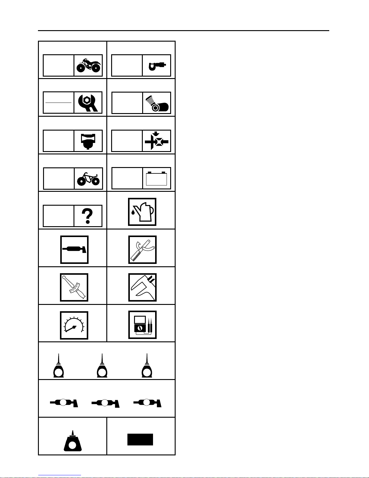
ILLUSTRATED SYMBOLS
Illustrated symbols 1 to 9 are printed on
the top right of each page and indicate the
subject of each chapter.
General information
Specifications
Periodic inspections and adjustments
Engine
Carburetion
Drive train
Chassis
Electrical
Troubleshooting
G
H
I
J
K
L
CHAS
90
ELEC
–+
TRBL
SHTG
AB
CD
T
.
R
.
EF
GHI
Illustrated symbols 0 to F are used to
identify the specifications appearing in the
text.
Filling fluid
Lubricant
Special tool
Torque
Wear limit, clearance
Engine speed
F
, V, A
Ω
Illustrated symbols G to L in the exploded
diagrams indicate the types of lubricants
and lubrication points.
E
JKL
B
M N
LT
G
LS
M
M
New
Apply engine oil
Apply gear oil
Apply molybdenum disulfide oil
Apply wheel bearing grease
Apply lightweight lithium-soap base grease
Apply molybdenum disulfide grease
Illustrated symbols M to N in the exploded
diagrams indicate where to apply a locking
agent M and when to install a new part N.
M Apply the locking agent (LOCTITE)
N Replace
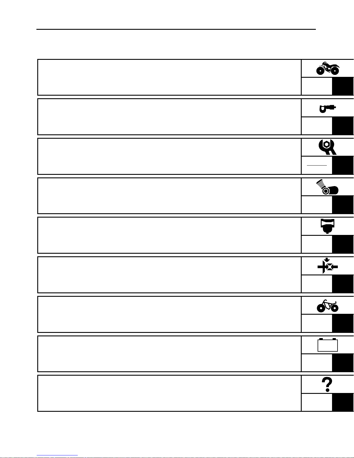
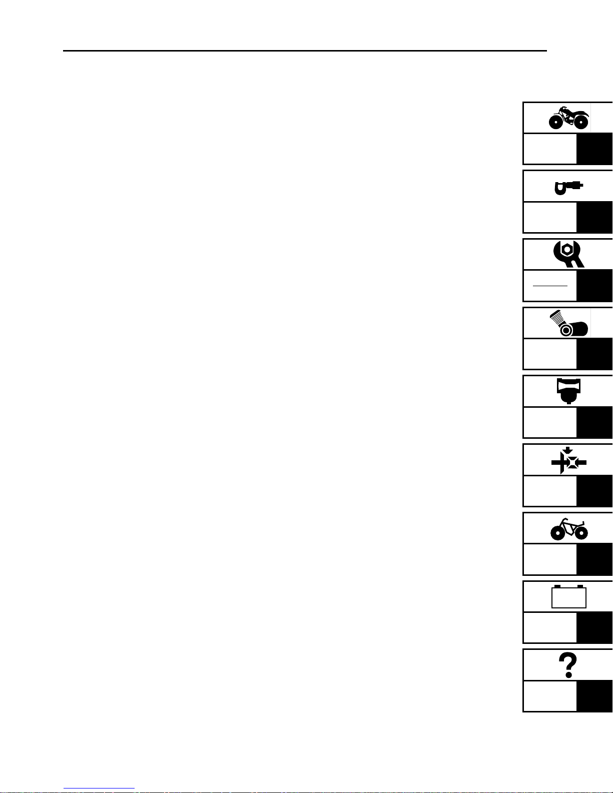
CHAPTER TITLES
GENERAL INFORMATION
SPECIFICATIONS
PERIODIC INSPECTION AND
ADJUSTMENT
ENGINE OVERHAUL
CARBURETION
GEN
INFO
SPEC
INSP
ADJ
ENG
CARB
1
2
3
4
5
DRIVE TRAIN
CHASSIS
ELECTRICAL
TROUBLESHOOTING
DRIVE
CHAS
–+
ELEC
TRBL
SHTG
6
7
8
9

CONTENTS
CHAPTER 1.
GENERAL INFORMATION
MACHINE IDENTIFICATION ........................................................................ 1-1
VEHICLE IDENTIFICATION NUMBER .................................................. 1-1
MODEL LABEL ...................................................................................... 1-1
IMPORTANT INFORMATION ...................................................................... 1-2
PREPARATION FOR REMOVAL PROCEDURES ................................. 1-2
REPLACEMENT PARTS ........................................................................ 1-2
GASKETS, OIL SEALS AND O-RINGS ................................................ 1-2
LOCK WASHERS/PLATES AND COTTER PINS .................................. 1-3
BEARINGS AND OIL SEALS ................................................................ 1-3
CIRCLIPS ............................................................................................... 1-3
CHECKING OF CONNECTIONS ................................................................... 1-4
SPECIAL TOOLS ........................................................................................... 1-5
CHAPTER 2.
SPECIFICATIONS
GENERAL SPECIFICATIONS ....................................................................... 2-1
MAINTENANCE SPECIFICATIONS ............................................................. 2-4
ENGINE ................................................................................................. 2-4
CHASSIS ............................................................................................. 2-14
ELECTRICAL ........................................................................................ 2-18
HOW TO USE THE CONVERSION TABLE ................................................ 2-20
GENERAL TORQUE SPECIFICATIONS ..................................................... 2-20
LUBRICATION POINTS AND LUBRICANT TYPES ................................... 2-21
ENGINE ............................................................................................... 2-21
CHASSIS ............................................................................................. 2-22
LUBRICATION DIAGRAMS ........................................................................ 2-23
CABLE ROUTING ....................................................................................... 2-25

PERIODIC INSPECTIONS AND ADJUSTMENTS
INTRODUCTION ........................................................................................... 3-1
PERIODIC MAINTENANCE/LUBRICATION ................................................ 3-1
FENDER AND FUEL TANK ........................................................................... 3-3
FRONT FENDER .................................................................................... 3-3
REAR FENDER ...................................................................................... 3-5
FUEL TANK ........................................................................................... 3-7
ENGINE ....................................................................................................... 3-10
VALVE CLEARANCE ADJUSTMENT ................................................. 3-10
TIMING CHAIN TENSIONER ADJUSTMENT ...................................3-12
IDLE SPEED ADJUSTMENT ..............................................................3-13
THROTTLE CABLE FREE PLAY ADJUSTMENT ................................ 3-14
SPEED LIMITER ADJUSTMENT ........................................................ 3-15
SPARK PLUG INSPECTION ...............................................................3-15
IGNITION TIMING CHECK .................................................................3-17
COMPRESSION PRESSURE MEASUREMENT ................................. 3-18
ENGINE OIL LEVEL INSPECTION ...................................................... 3-19
ENGINE OIL REPLACEMENT ............................................................. 3-20
CLUTCH ADJUSTMENT ....................................................................3-23
AIR FILTER CLEANING ....................................................................... 3-23
CHAPTER 3.
GEN
INFO
SPEC
INSP
ADJ
ENG
CARB
1
2
3
4
5
CHASSIS ..................................................................................................... 3-26
FRONT AND REAR BRAKE LINING INSPECTION ............................ 3-26
FRONT BRAKE ADJUSTMENT .......................................................... 3-26
REAR BRAKE LEVER AND PEDAL ADJUSTMENT ..........................3-27
DRIVE SELECT LEVER POSITION ADJUSTMENT ...........................3-29
FINAL DRIVE GEAR OIL LEVEL INSPECTION ................................... 3-29
FINAL DRIVE GEAR OIL REPLACEMENT .......................................... 3-30
DRIVE SHAFT DUST BOOT INSPECTION ......................................... 3-31
STEERING SYSTEM INSPECTION .................................................... 3-31
TOE-IN ADJUSTMENT ....................................................................... 3-32
FRONT AND REAR SHOCK ABSORBERS INSPECTION .................. 3-34
REAR SHOCK ABSORBER ADJUSTMENT ....................................... 3-34
TIRE INSPECTION ..............................................................................3-35
WHEEL INSPECTION .......................................................................... 3-37
DRIVE
CHAS
–+
ELEC
TRBL
SHTG
6
7
8
9

ELECTRICAL ............................................................................................... 3-38
BATTERY INSPECTION ...................................................................... 3-38
FUSE INSPECTION ............................................................................. 3-41
HEADLIGHT BEAM ADJUSTMENT ................................................... 3-42
HEADLIGHT BULB REPLACEMENT .................................................. 3-42
CHAPTER 4.
ENGINE OVERHAUL
ENGINE REMOVAL ...................................................................................... 4-1
PREPARATION FOR REMOVAL ........................................................... 4-1
FRONT FENDER AND REAR FENDER ................................................. 4-1
ENGINE OIL ..........................................................................................4-2
EXHAUST PIPE AND MUFFLER .......................................................... 4-2
CARBURETOR ...................................................................................... 4-2
STARTER MOTOR ................................................................................ 4-3
REAR BRAKE CABLES AND FOOTREST ............................................4-3
WIRINGS AND HOSES ......................................................................... 4-3
REAR WHEEL DRIVE ASSEMBLY AND SWINGARM ........................4-4
ENGINE REMOVAL ..............................................................................4-4
ENGINE DISASSEMBLY .............................................................................. 4-5
CYLINDER HEAD ASSEMBLY, CYLINDER AND PISTON .................. 4-5
STARTER PULLEY CDI MAGNETO ..................................................... 4-8
MIDDLE DRIVEN PINION GEAR ........................................................ 4-10
PRIMARY AND SECONDARY CLUTCHES ........................................ 4-11
OIL PUMP AND SHIFTER ................................................................... 4-13
BALANCER DRIVEN GEAR ................................................................ 4-14
CRANKCASE (LEFT) ........................................................................... 4-15
BALANCER SHAFT, TRANSMISSION AND CRANKSHAFT ............ 4-16
CYLINDER HEAD ................................................................................ 4-17
VALVE ................................................................................................. 4-18
RECOIL STARTER ............................................................................... 4-19
INSPECTION AND REPAIR ........................................................................ 4-20
CYLINDER HEAD ................................................................................ 4-20
INTAKE AND EXHAUST VALVE ........................................................ 4-20
VALVE GUIDE ..................................................................................... 4-21
VALVE SEAT ....................................................................................... 4-22
VALVE SPRING ................................................................................... 4-25
VALVE INSTALLATION ...................................................................... 4-26
CAM SHAFT ........................................................................................ 4-27
ROCKER ARM AND ROCKER ARM SHAFT ...................................... 4-28

TIMING CHAIN ...................................................................................4-30
CAM SPROCKET AND CAM DRIVE SPROCKET ............................... 4-31
TIMING CHAIN GUIDE ....................................................................... 4-31
TIMING CHAIN TENSIONER .............................................................. 4-31
TAPPET COVER AND CAM SPROCKET COVER ............................... 4-32
CYLINDER AND PISTON .................................................................... 4-32
PISTON RING AND PISTON PIN ....................................................... 4-33
CRANKSHAFT ..................................................................................... 4-36
BALANCER DRIVE GEAR AND DRIVEN GEARS .............................. 4-37
PRIMARY GEARS AND STARTER ..................................................... 4-37
PRIMARY CLUTCH ............................................................................. 4-38
SECONDARY CLUTCH ....................................................................... 4-38
OIL PUMP ............................................................................................ 4-40
TRANSMISSION AND SHIFTER ........................................................ 4-41
MIDDLE GEAR .................................................................................... 4-43
BEARINGS AND OIL SEALS .............................................................. 4-43
CIRCLIPS AND WASHERS ................................................................. 4-43
CRANKCASE ....................................................................................... 4-43
RECOIL STARTER ............................................................................... 4-44
GEN
INFO
SPEC
INSP
ADJ
1
2
3
ENGINE ASSEMBLY AND ADJUSTMENT ............................................... 4-45
RECOIL STARTER ............................................................................... 4-45
CRANKSHAFT/BALANCER ................................................................ 4-47
TRANSMISSION ................................................................................. 4-48
SHIFTER .............................................................................................. 4-49
CRANKSHAFT, TRANSMISSION AND BALANCER SHAFT ............ 4-50
CRANKCASE (LEFT) ........................................................................... 4-51
BALANCER DRIVEN AND DRIVE GEARS ......................................... 4-51
SHIFT SHAFT/OIL PUMP .................................................................... 4-53
SHIFTER AND OIL PUMP ................................................................... 4-54
CLUTCH ............................................................................................... 4-56
PRIMARY AND SECONDARY CLUTCHES ........................................ 4-57
MIDDLE DRIVEN PINION GEAR ........................................................ 4-61
STARTER PULLEY (EXCEPT FOR USA)/CDI MAGNETO ................. 4-62
STARTER PULLEY (EXCEPT FOR USA) AND CDI MAGNETO ........ 4-63
CYLINDER AND CYLINDER HEAD ASSEMBLY ................................ 4-65
PISTON, CAMSHAFT AND TIMING CHAIN ...................................... 4-66
CYLINDER HEAD ASSEMBLY, CYLINDER AND PISTON ................ 4-67
REMOUNTING ENGINE ..................................................................... 4-72
ENG
4
CARB
5
DRIVE
6
CHAS
7
–+
ELEC
8
TRBL
SHTG
9

CHAPTER 5.
CARBURETION
CARBURETOR .............................................................................................. 5-1
REMOVAL ............................................................................................. 5-2
DISASSEMBLY ..................................................................................... 5-2
INSPECTION ......................................................................................... 5-4
ASSEMBLY ........................................................................................... 5-6
INSTALLATION ..................................................................................... 5-8
FUEL LEVEL ADJUSTMENT ................................................................ 5-9
CHAPTER 6.
DRIVE TRAIN
MIDDLE GEAR SERVICE .............................................................................. 6-1
MIDDLE GEAR ...................................................................................... 6-1
MIDDLE GEAR SHIMS .........................................................................6-2
REMOVAL ............................................................................................. 6-3
DISASSEMBLY ..................................................................................... 6-5
INSPECTION ......................................................................................... 6-7
MIDDLE GEAR SHIM SELECTION ....................................................... 6-9
ASSEMBLY ......................................................................................... 6-16
MIDDLE GEAR LASH ADJUSTMENT ...............................................6-21
INSTALLATION ................................................................................... 6-22
FINAL DRIVE GEAR AND DRIVE SHAFT .................................................. 6-24
TROUBLESHOOTING ......................................................................... 6-25
REMOVAL ........................................................................................... 6-28
DISASSEMBLY ................................................................................... 6-29
INSPECTION ....................................................................................... 6-31
FINAL DRIVE PINION GEAR
AND RING GEAR SHIM SELECTION ............................................. 6-32
ASSEMBLY ......................................................................................... 6-35
FINAL GEAR GEAR LASH MEASUREMENT
AND ADJUSTMENT ....................................................................... 6-37
INSTALLATION ................................................................................... 6-40
CHAPTER 7.
CHASSIS
FRONT WHEELS AND FRONT BRAKE ....................................................... 7-1
REMOVAL ............................................................................................. 7-2
INSPECTION ......................................................................................... 7-3
INSTALLATION ..................................................................................... 7-6
REAR WHEELS/REAR BRAKE AND REAR AXLE ....................................... 7-9
REMOVAL ........................................................................................... 7-11
INSPECTION ....................................................................................... 7-13
INSTALLATION ................................................................................... 7-16
GEN
INFO
SPEC
1
2
STEERING SYSTEM ................................................................................... 7-20
REMOVAL ........................................................................................... 7-21
INSPECTION ....................................................................................... 7-23
INSTALLATION ................................................................................... 7-24
FRONT SHOCK ABSORBER AND FRONT ARM ....................................... 7-28
REMOVAL ........................................................................................... 7-29
INSPECTION ....................................................................................... 7-31
INSTALLATION ................................................................................... 7-32
REAR SHOCK ABSORBER AND SWINGARM .......................................... 7-35
REMOVAL ........................................................................................... 7-36
INSPECTION ....................................................................................... 7-38
INSTALLATION ................................................................................... 7-40
CHAPTER 8.
ELECTRICAL
ELECTRICAL COMPONENTS ...................................................................... 8-1
INSP
ADJ
ENG
CARB
DRIVE
CHAS
3
4
5
6
7
SWITCH INSPECTION .................................................................................. 8-2
SWITCH INSPECTION .......................................................................... 8-2
INSPECTING A SWITCH SHOWN IN THE MANUAL ......................... 8-2
SWITCH CONTINUITY INSPECTION ................................................... 8-4
CHECKING OF BULBS (FOR HEADLIGHT) .................................................. 8-6
CHECKING BULBS CONDITION .......................................................... 8-6
–+
ELEC
TRBL
SHTG
8
9

IGNITION SYSTEM ......................................................................................8-7
CIRCUIT DIAGRAM ..............................................................................8-7
TROUBLESHOOTING ........................................................................... 8-8
ELECTRIC STARTING SYSTEM .................................................................8-12
CIRCUIT DIAGRAM ............................................................................8-12
STARTING CIRCUIT OPERATION .....................................................8-13
TROUBLESHOOTING ......................................................................... 8-14
STARTER MOTOR .............................................................................. 8-18
STARTER MOTOR INSPECTION ....................................................... 8-19
STARTER MOTOR ASSEMBLY ......................................................... 8-20
CHARGING SYSTEM .................................................................................8-21
CIRCUIT DIAGRAM ............................................................................8-21
TROUBLESHOOTING ......................................................................... 8-22
LIGHTING SYSTEM ....................................................................................8-24
CIRCUIT DIAGRAM ............................................................................8-24
TROUBLESHOOTING ......................................................................... 8-25
LIGHTING SYSTEM CHECK ............................................................... 8-27
SIGNAL SYSTEM ....................................................................................... 8-29
CIRCUIT DIAGRAM ............................................................................8-29
TROUBLESHOOTING ......................................................................... 8-30
SIGNAL SYSTEM CHECK ..................................................................8-32
CHAPTER 9.
TROUBLESHOOTING
STARTING FAILURE/HARD STARTING .....................................................9-1
FUEL SYSTEM ...................................................................................... 9-1
ELECTRICAL SYSTEM .......................................................................... 9-1
COMPRESSION SYSTEM .................................................................... 9-2
POOR IDLE SPEED PERFORMANCE ...........................................................9-2
POOR IDLE SPEED PERFORMANCE ................................................... 9-2
POOR MEDIUM AND HIGH-SPEED PERFORMANCE ................................ 9-2
POOR MEDIUM AND HIGH-SPEED PERFORMANCE ........................ 9-2
FAULTY DRIVE TRAIN .................................................................................9-3
FAULTY GEAR SHIFTING ............................................................................9-4
HARD SHIFTING ................................................................................... 9-4
SHIFT PEDAL DOES NOT MOVE ......................................................... 9-4
JUMPS OUT OF GEAR ......................................................................... 9-4
CLUTCH SLIPPING ....................................................................................... 9-4
CLUTCH SLIPPING ............................................................................... 9-4
GEN
INFO
1
CLUTCH DRAGGING ....................................................................................9-4
CLUTCH DRAGGING ............................................................................ 9-4
OVERHEATING ............................................................................................. 9-5
OVERHEATING ..................................................................................... 9-5
FAULTY BRAKE ............................................................................................ 9-5
POOR BRAKING EFFECT .....................................................................9-5
SHOCK ABSORBER MALFUNCTION ..........................................................9-5
MALFUNCTION .................................................................................... 9-5
UNSTABLE HANDLING ...............................................................................9-6
UNSTABLE HANDLING .......................................................................9-6
LIGHTING SYSTEM ......................................................................................9-6
HEADLIGHT DARK ...............................................................................9-6
BULB BURNT OUT ............................................................................... 9-6
SPEC
INSP
ADJ
ENG
CARB
DRIVE
2
3
4
5
6
CHAS
–+
ELEC
TRBL
SHTG
7
8
9
GEN
MACHINE IDENTIFICATION
GENERAL INFORMATION
MACHINE IDENTIFICATION
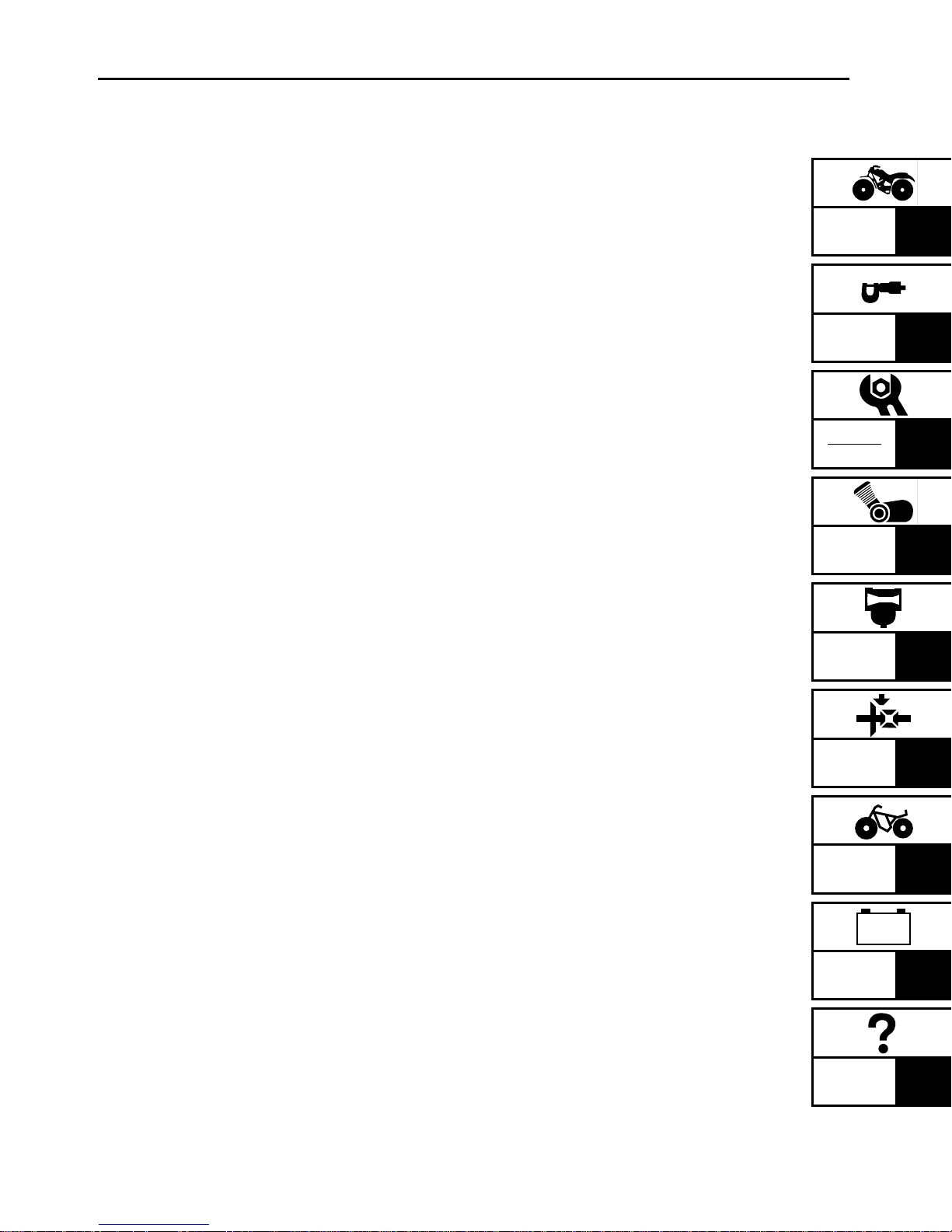
VEHICLE IDENTIFICATION NUMBER
The vehicle identification number 1 is
stamped into the left side of the frame.
INFO
1
MODEL LABEL
The model label 1 is affixed to the frame.
This information will be needed to order
spare parts.
1 - 1

1
GEN
IMPORTANT INFORMATION
EB101000
IMPORTANT INFORMATION
PREPARATION FOR REMOVAL
PROCEDURES
1.Remove all dirt, mud, dust and foreign
material before removal and disassembly.
2.Use proper tools and cleaning equipment.
Refer to the “SPECIAL TOOLS” section.
3.When disassembling the machine, always
keep mated parts together. This includes
gears, cylinder, piston and other parts that
have been “mated” through normal wear.
Mated parts must always be reused or
replaced as an assembly.
4.During machine disassembly, clean all
parts and place them in trays in the order
of disassembly. This will speed up assembly and allow for the correct installation of
all parts.
5.Keep all parts away from any source of
fire.
INFO
EB101010
REPLACEMENT PARTS
1.Use only genuine Yamaha parts for all
replacements. Use oil and grease recommended by Yamaha for all lubrication
jobs. Other brands may be similar in function and appearance, but inferior in quality.
EB101020
GASKETS, OIL SEALS AND O-RINGS
1.Replace all gaskets, seals and O-rings
when overhauling the engine. All gasket
surfaces, oil seal lips and O-rings must be
cleaned.
2.Properly oil all mating parts and bearings
during reassembly. Apply grease to the oil
seal lips.
1 - 2
1
1
4
GEN
IMPORTANT INFORMATION
EB101030
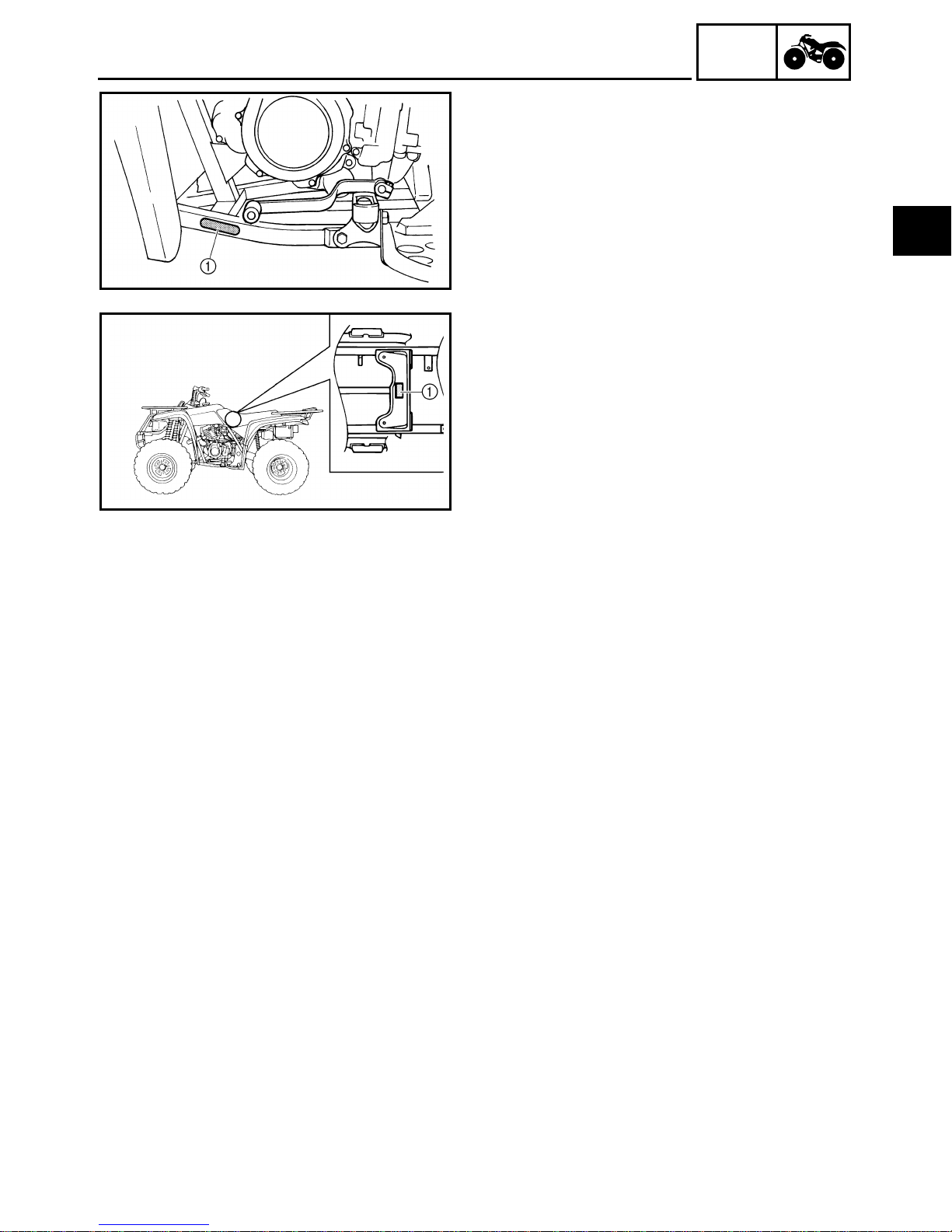
LOCK WASHERS/PLATES AND COTTER
PINS
1.Replace all lock washers/plates 1 and cotter pins after removal. Bend lock tabs
along the bolt or nut flats after the bolt or
nut has been tightened to specification.
INFO
1
EB101040
BEARINGS AND OIL SEALS
1.Install bearings and oil seals so that the
manufacturer’s marks or numbers are visible. When installing oil seals, apply a
light coating of lightweight lithium base
grease to the seal lips. Oil bearings liberally when installing, if appropriate.
Oil seal
CAUTION:
Do not use compressed air to spin the bearings dry. This will damage the bearing surfaces.
Bearing
EB101050
CIRCLIPS
1.Check all circlips carefully before reassembly. Always replace piston pin clips
after one use. Replace distorted circlips.
When installing a circlip 1 , make sure
that the sharp-edged corner 2 is positioned opposite the thrust 3 it receives.
See sectional view.
Shaft
1 - 3
1
CHECKING OF CONNECTIONS
EB801000
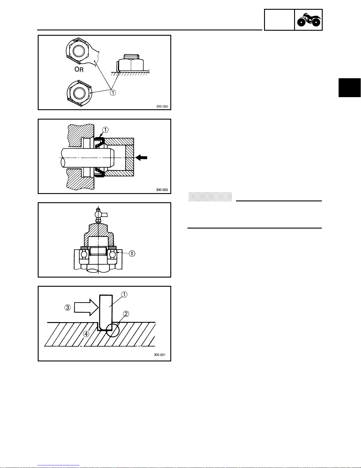
CHECKING OF CONNECTIONS
Check the connectors for stains, rust, moisture, etc.
1.Disconnect:
●
Connector
2.Check:
Connector
●
Moisture
blower.
Stains/rust
terminals several times.
3.Check:
●
Connector leads
Looseness
nect the terminals.
→
Dry each terminal with an air
→
Connect and disconnect the
→
Bend up the pin 1 and con-
GEN
INFO
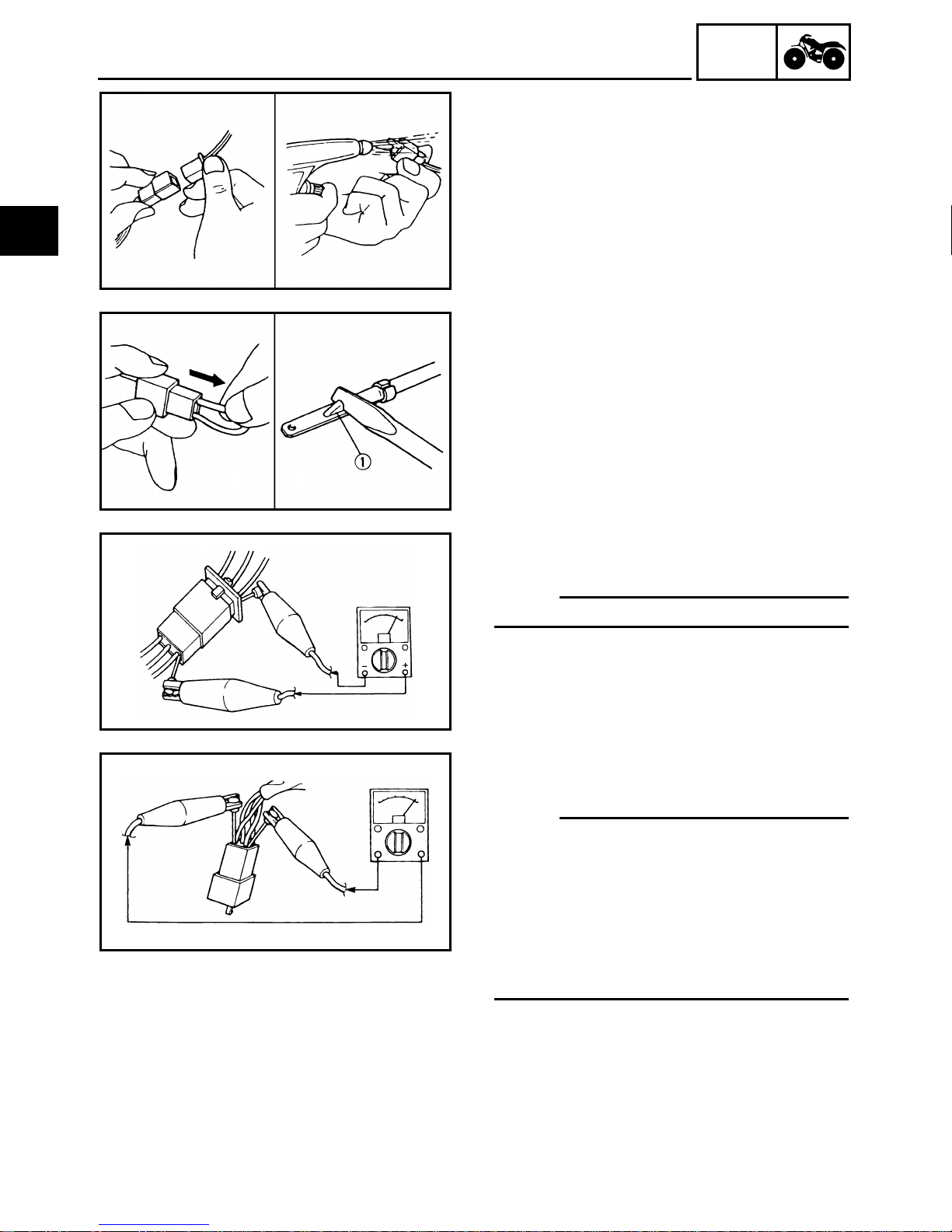
4.Connect:
●
Connector terminals
NOTE:
The two terminals “click” together.
5.Check:
Continuity (using a pocket tester)
●
NOTE:
If there is no continuity, clean the termi-
●
nals.
●
When checking the wire harness be sure
to perform steps 1 to 3.
As a quick remedy, use a contact revital-
●
izer available at most part stores.
●
Check the connector with a pocket tester
as shown.
1 - 4
GEN
SPECIAL TOOLS
EB102001
SPECIAL TOOLS
The following special tools are necessary for complete and accurate tune-up and assembly.
Use only the appropriate special tools; this will help prevent damage caused by the use of
inappropriate tools or improvised techniques. Special tools may differ by shape and part
number from country to country. In such a case, two types are provided.
When placing an order, refer to the list provided below to avoid any mistakes.
For US and CDN Except for US and CDN
P/N. YM-, YU-, YS-, YK-, ACC- P/N. 90890-
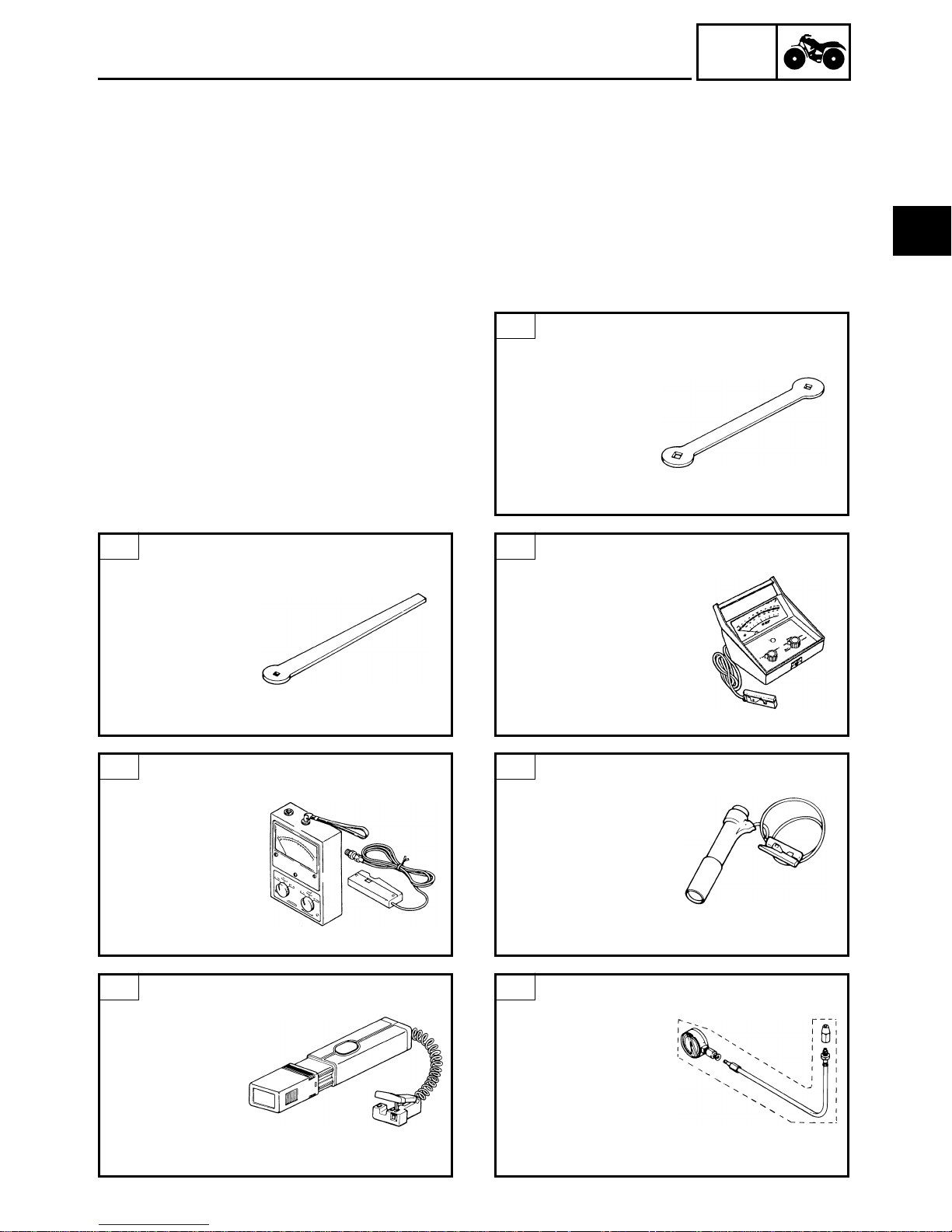
1-A
Valve adjusting tool 3mm (0.12 in)
P/N. YM-08035
FOR TUNE UP
INFO
1
1-B
Valve adjusting tool 3mm (0.12 in)
P/N. 90890-01311
This tool is necessary for adjusting the valve
clearance.
2-B
Engine tachometer
P/N. 90890-03113
This tool is needed to measure engine rpm.
This tool is necessary for adjusting the valve
clearance.
2-A
Inductive tachometer
P/N. YU-8036-A
This tool is needed to measure engine rpm.
3-A
Timing light
P/N. YM-33277-A
This tool is necessary for checking ignition
timing.
3-B
Timing light
P/N. 90890-03141
This tool is necessary for checking ignition
timing.
4-A
Compression gauge
P/N. YU-33223
Adapter (M12)
P/N. YU-33223-3
These gauge are used to measure the engine
compression.
1 - 5
SPECIAL TOOLS
GEN
INFO
1
4-B
Compression gauge
P/N. 90890-03081
Extension
P/N. 90890-04082
This gauge is used to measure the engine
compression.
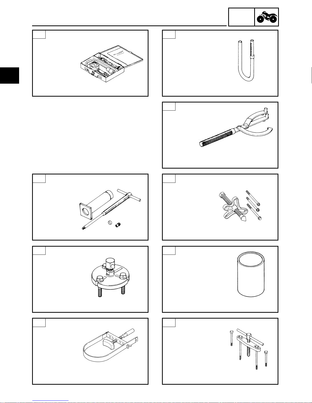
FOR ENGINE SERVICE
2
Piston pin puller
P/N. YU-01304
P/N. 90890-01304
5
Fuel level gauge
P/N. YM-01312-A
P/N. 90890-01312
This gauge is used to measure the fuel level in
the float chamber.
1
Rotor holder
P/N. YU-01235
P/N. 90890-01235
This tool is used to hold the starter pulley and
clutch when removing or installing the starter
pulley and clutch boss securing nut.
3-A
Flywheel puller
P/N. YU-33270
This tool is used to remove the piston pin.
3-B
Flywheel puller
P/N. 90890-01362
This tool is used to remove the flywheel magnet rotor.
5
Sheave holder
P/N. YS-01880
P/N. 90890-01701
This tool is used to holder the flywheel magnet rotor when removing or installing the
rotor securing nut.
This tool is used to remove the flywheel magnet rotor.
4
Flywheel puller attachment
P/N. YM-33278
P/N. 90890-04087
This tool is used to remove the flywheel magnet rotor and crankcase.
6
Crankcase separating tool
P/N. YU-01135-A
P/N. 90890-01135
This tool is used when separating the crankcase.
1 - 6
SPECIAL TOOLS
GEN
INFO
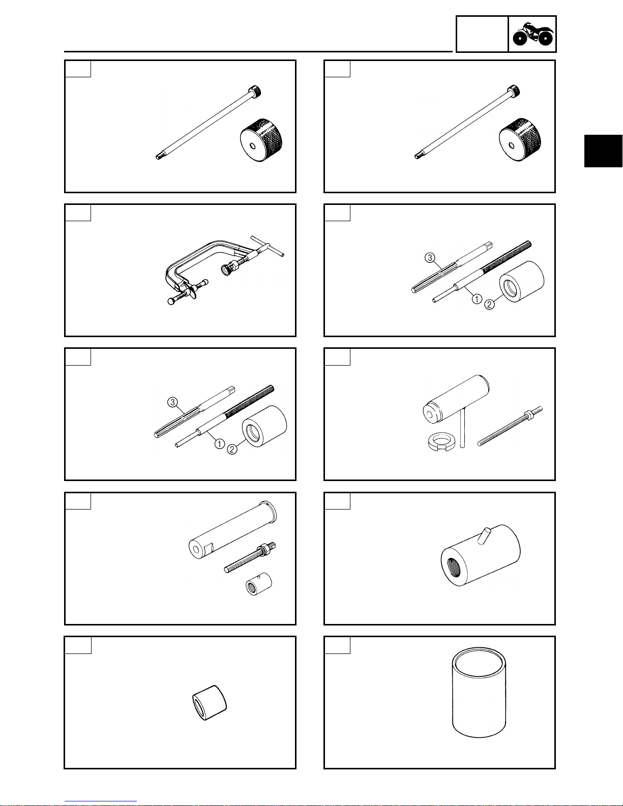
7-A
Slide hammer set
P/N. YU-01083-A
These tools are used when removing the
rocker arm shaft.
8
Valve spring compressor
P/N. YM-04019
P/N. 90890-04019
This tool is useed to remove and install the
valve assemblies.
9-B
Valve guide remover and installer set
6mm (0.24 in)
Valve guide remover
P/N. 90890-04064- 1
Valve guide installer
P/N. 90890-04065-2
Valve guide reamer
P/N. 90890-04066-3
These tools are used to remove, install and rebore
the valve guide.
7-B
Slide hammer bolt (M6)
P/N. 90890-01083
Weight
P/N. 90890-01084
1
These tools are used when removing the
rocker arm shaft.
9-A
Valve guide remover and installer 6mm (0.24 in)
Valve guide remover
P/N. YM-4064-A-1
Valve guide installer
P/N. YM-04065-A-2
Valve guide reamer
P/N. YM-04066-3
These tools are used to remove, install and rebore
the valve guide.
10-A
Crankshaft installer set
P/N. YU-90050
These tools are used to install the crankshaft
and balancer drive gear.
10-B
Buffer boss installer set
P/N. 90890-04088
These tools are used to install the crankshaft
and balancer drive gear.
12-A
Pot spacer
P/N. YM-90070-A
This tool is used to install the crankshaft and
balancer drive gear.
11
Adapter #11
P/N. YM-33279
This tool is used to install the crankshaft and
balancer drive gear.
12-B
Crankshaft spacer
P/N. 90890-04060
This tool is used to install the crankshaft and
balancer drive gear.
1 - 7
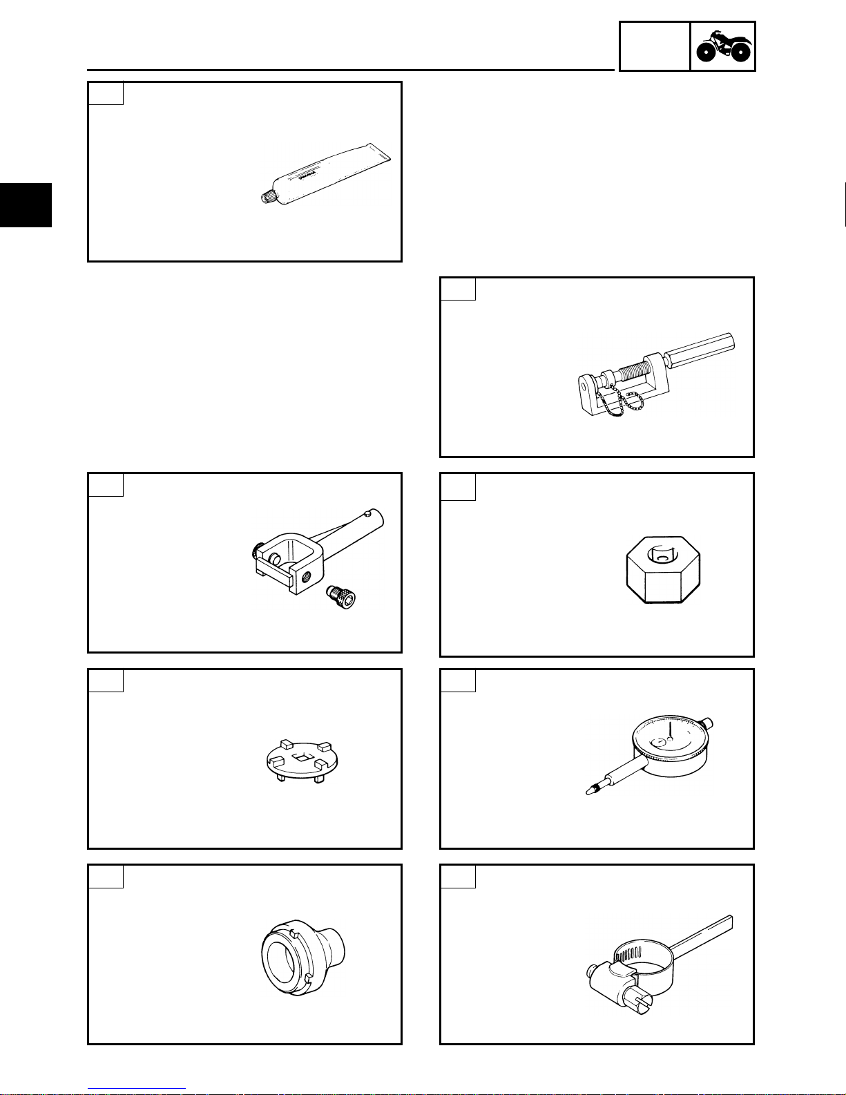
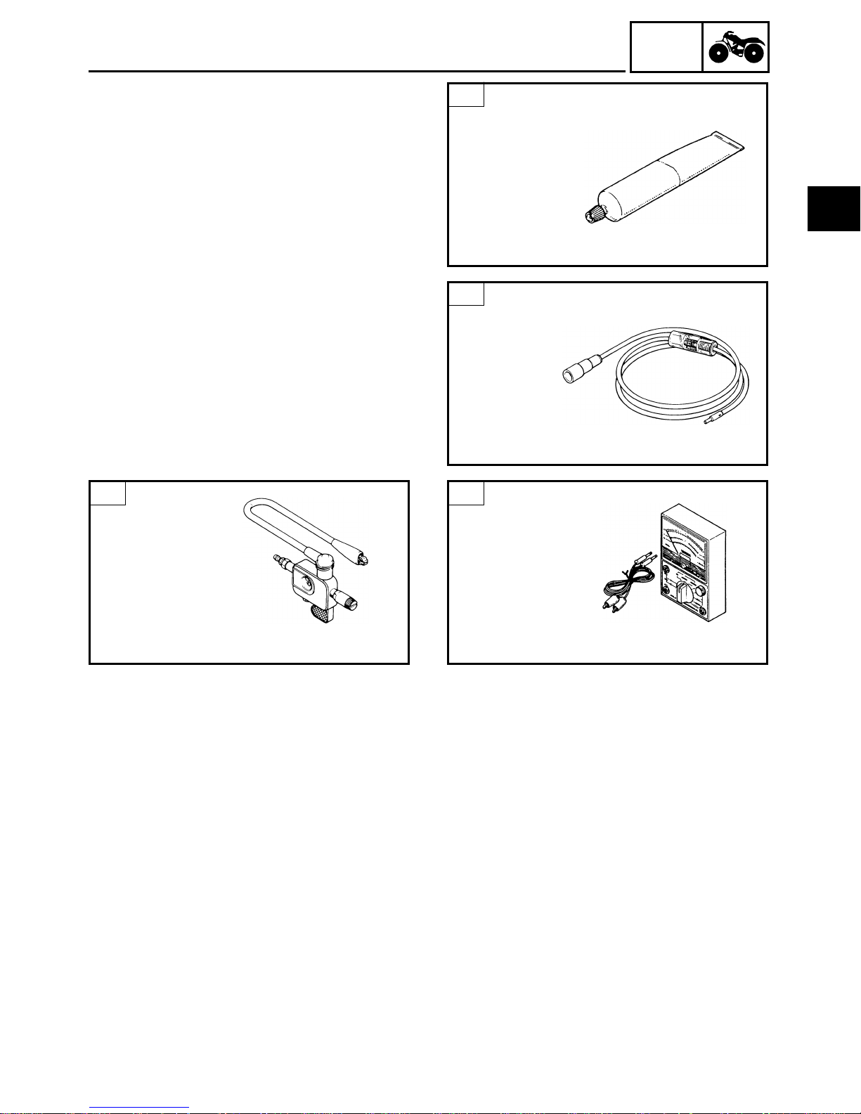
13
Sealant (Quick Gasket)
P/N. ACC-QUICK-GS-KT
YAMAHA bond No. 1215
P/N. 90890-85505
SPECIAL TOOLS
GEN
INFO
1
This sealant (bond) is used for crankcase mating surface, etc.
FOR DRIVE TRAIN SERVICE
1-B
Universal joint holder
P/N. 90890-04062
Attachment
P/N. 90890-04096
1-A
Universal joint holder
P/N. YM-04062
Attachment
P/N. YM-33291
These tools are used to remove and install the
universal joint.
2
Bearing retainer wrench
P/N. YM-33289
P/N. 90890-04104
These tools are used to remove and install the
universal joint.
3
Ring nut wrench
P/N. YM-1391
P/N. 90890-01391
This tool is used to remove and install the
reverse gear.
5
Bearing retainer wrench
P/N. YM-04050
P/N. 90890-04050
This tool is used to remove and install the
final gear bearing retainer.
This tool is used to disassemble and reassemble the bearing.
4
Dial gauge
P/N. YM-03097
P/N. 90890-03097
This tool is used to measure the gear lash for
the middle gear and final gear.
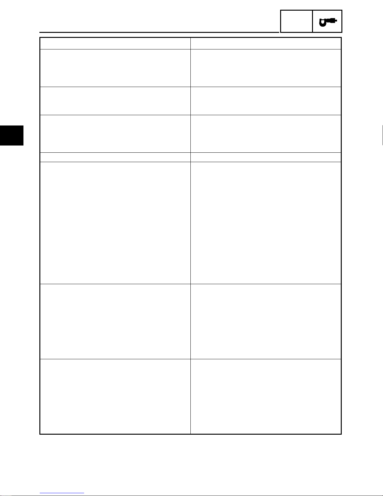
6
Gear lash measurment tool
P/N. YM-01231
P/N. 90890-01231
This tool is used to measure the gear lash.
1 - 8
FOR CHASSIS SERVICE
SPECIAL TOOLS
1
Yamaha brake grease
P/N. 90793-40003
GEN
INFO
FOR ELECTRICAL
COMPONENTS
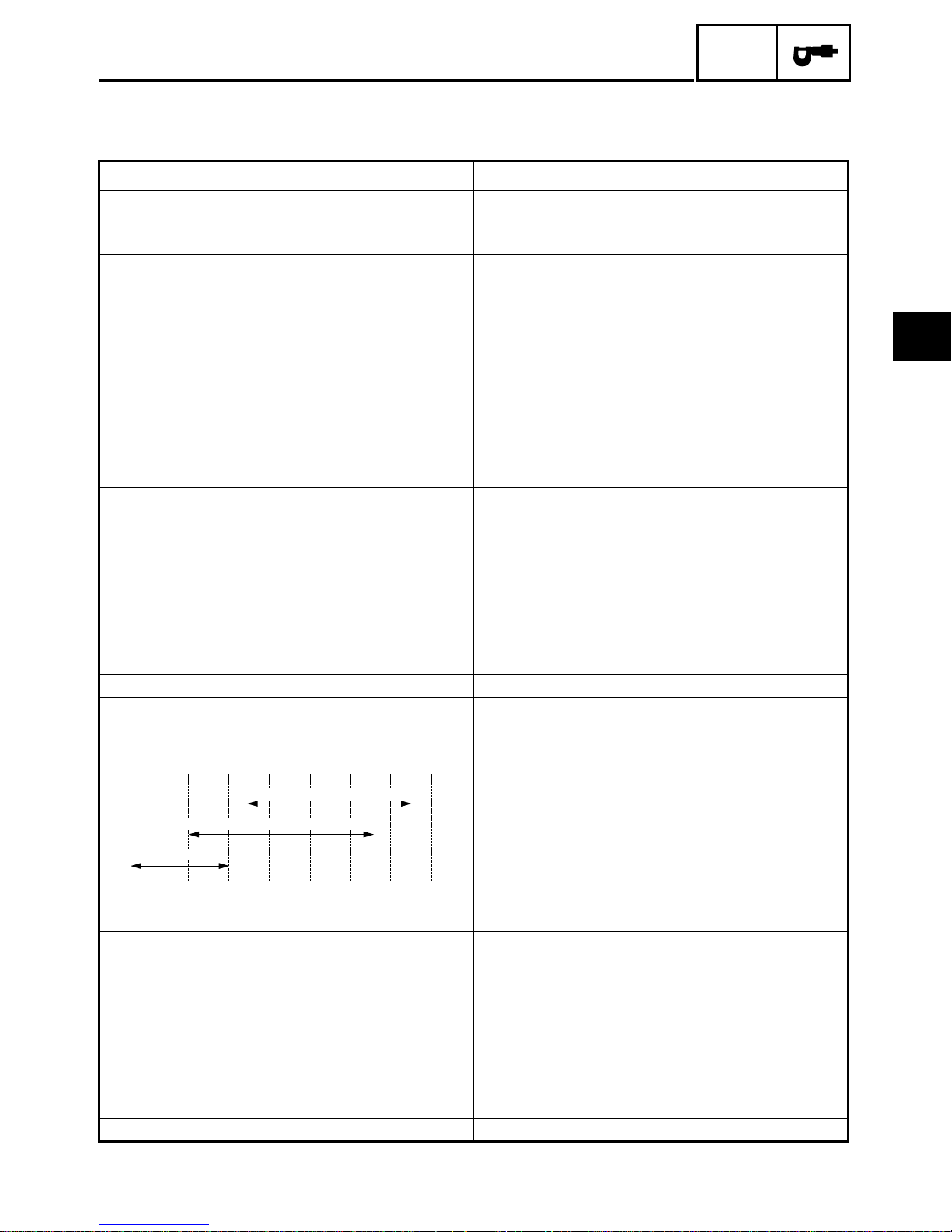
1-B
Ignition checker
P/N. 90890-06754
This Yamaha brake grease is used for rear
1
brake dust seal.
1-A
Dynamic spark tester
P/N. YM-34487
This instrument is necessary for checking the
ignition system components.
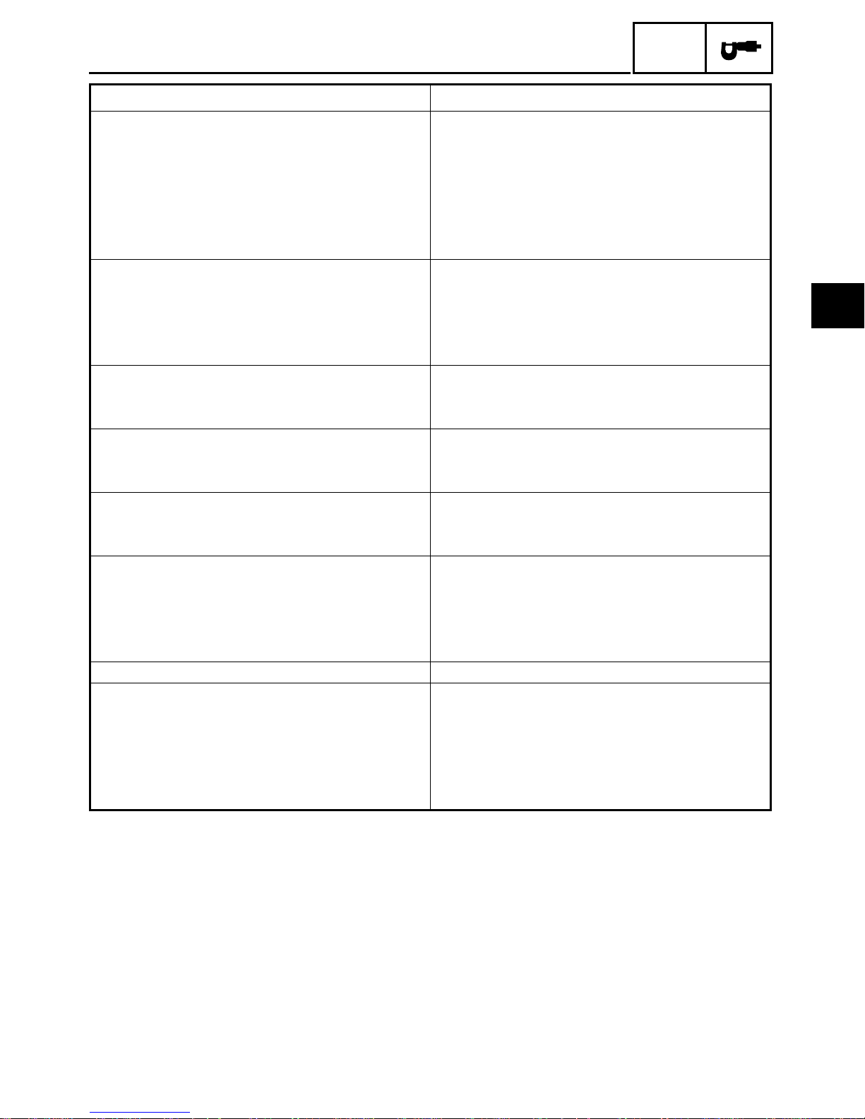
2
Pocket tester
P/N. YU-03112
P/N. 90890-03112
This instrument is necessary for checking the
ignition system components.
This instrument is invaluable for checking the
electrical system.
1 - 9

1
GEN
INFO
1 - 10
GENERAL SPECIFICATIONS
SPECIFICATIONS
GENERAL SPECIFICATIONS
Item Standard
Model code: 4XE1 (USA)
4XE2 (CAL)
4XE3 (CDN)
Dimensions:
Overall length 1,940 mm (76.4 in)
Overall width 1,005 mm (39.6 in)
Overall height 1,118 mm (44.0 in)
Seat height 780 mm (30.7 in)
Wheelbase 1,170 mm (46.1 in)
Minimum ground clearance 155 mm (6.1 in)
Minimum turning radius 2,900 mm (114 in)
Basic weight:
With oil and full fuel tank 215 kg (474 lb)
Engine:
Engine type Air-cooled 4-stroke, SOHC
Cylinder arrangement Forward-inclined single cylinder
Displacement 229.6 cm
Bore
×
stroke 71 × 58 mm (2.795 × 2.283 in)
Compression ratio 8.7 : 1
Compression pressure 900 kPa (9.0 kg/cm
Starting system Electric and recoil starter
Lubrication system: Wet sump
Oil type or grade:
Engine oil
0° 10° 30° 50° 70° 90° 110°F
YAMALUBE 4 (20W40) or SAE 20W40
3
2
, 128 psi)
SPEC
2
YAMALUBE 4 (10W30) or SAE 10W30
SAE 5W30
-20° -10° 0° 10° 20° 30° 40°C
Final gear oil SAE80API “GL-4” Hypoid Gear Oil
Oil capacity:
Engine oil
Periodic oil change 1.5 L (1.3 Imp qt, 1.6 US qt)
With oil filter replacement 1.6 L (1.4 Imp qt, 1.7 US qt)
Total amount 1.8 L (1.6 Imp qt, 1.9 US qt)
Final gear case oil
Periodic oil change 0.25 L (0.21 Imp qt, 0.27 US qt)
Total amount 0.27 L (0.24 Imp qt, 0.29 US qt)
Air filter: Dry type element
2 - 1
2
GENERAL SPECIFICATIONS
Item Standard
Fuel:
Type Unleaded fuel
Fuel tank capacity 12 L (2.64 Imp gal, 3.17 US gal)
Fuel reserve amount 1.6 L (0.35 Imp gal, 0.42 US gal)
Carburetor:
Type / quantity BST34/1
Manufacturer MIKUNI
Spark plug:
Type DR7EA
Manufacturer NGK
Spark plug gap 0.6 ~ 0.7 mm (0.024 ~ 0.028 in)
Clutch type Wet, centrifugal automatic
Transmission:
Primary reduction system Spur gear
Primary reduction retio 73/22 (3.318)
Secondary reduction system Shaft drive
Secondary reduction ratio 19/18 × 46/11 (4.414)
Transmission type Constant mesh 5-speed
Operation Left foot operation
Gear ratio: 1st 34/12 (2.833)
2nd 34/19 (1.789)
3rd 29/22 (1.318)
4th 26/25 (1.040)
5th 23/28 (0.821)
Reverse gear ratio 73/22 × 34/12 × 19/18 × 46/11 (41.500)
Chassis:
Frame type Steel tube frame
Caster angle 4˚
Kingpin angle 13˚
Trail 20 mm (0.79 in)
Tread (STD) front 785 mm (30.9 in)
Tread (STD) rear 770 mm (30.3 in)
Toe-in 0 ~ 5 mm (0 ~ 0.20 in)
Tire:
Type Tubeless
Size front AT22 × 7-10
rear AT22 × 10-10
Manufacturer front CARLISLE/DUNLOP
rear CARLISLE/DUNLOP
Type front TRAIL WOLF/KT701
rear TRAIL WOLF/KT705
SPEC
2 - 2
GENERAL SPECIFICATIONS
Item Standard
Tire pressure (cold tire):
Recommended front 20 kPa (0.20 kg/cm
rear 25 kPa (0.25 kg/cm
Minimum front 17 kPa (0.17 kg/cm
rear 22 kPa (0.22 kg/cm
Maximum front 23 kPa (0.23 kg/cm
rear 28 kPa (0.28 kg/cm
Brake:
Front brake type Drum brake
operation Right hand operation
Rear brake type Drum brake (full sealed)
operation Left hand and right foot operation
Suspension:
Front suspension Strut
Rear suspension Swingarm (monocross)
Shock absorber:
Front shock absorber Coil spring / oil damper
Rear shock absorber Coil spring / oil damper
Wheel travel:
Front wheel travel 125 mm (4.92 in)
Rear wheel travel 135 mm (5.31 in)
Electrical:
Ignition system C.D.I.
Generator system A.C. magneto
Battery type YB14A-A2
Battery capacity 12 V 14 AH
Headlight type: Bulb type
Bulb wattage × quantity:
Headlight 12 V 25 W/ 25 W × 2
Tail light 12 V 7.5 W × 1
Indicator lights:
Neutral 12 V 3.4 W × 1
Reverse 12 V 3.4 W × 1
2
, 2.9 psi)
2
, 3.6psi)
2
, 2.5 psi)
2
, 3.2 psi)
2
, 3.3 psi)
2
, 4.0 psi)
SPEC
2
2 - 3
2
MAINTENANCE SPECIFICATIONS
SPEC
MAINTENANCE SPECIFICATIONS
ENGINE
Item Standard Limit
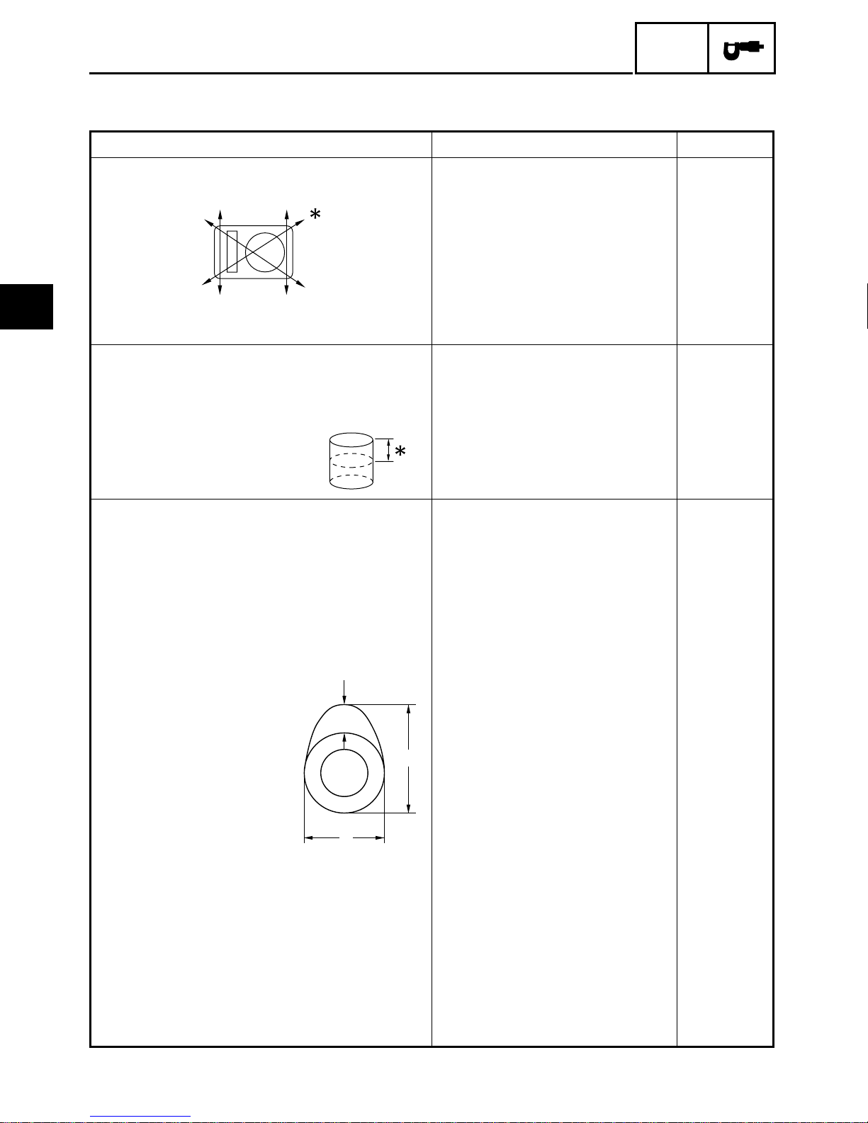
Cylinder head:
Warp limit ---- 0.10 mm
(0.004 in)
Measuring point Lines indicate straight edge
Cylinder:
Bore size 70.97 ~ 71.02 mm (2.794 ~ 2.796 in) 71.10 mm
Measuring point 40 mm (1.6 in) ----
*
*
measurement.
(2.799 in)
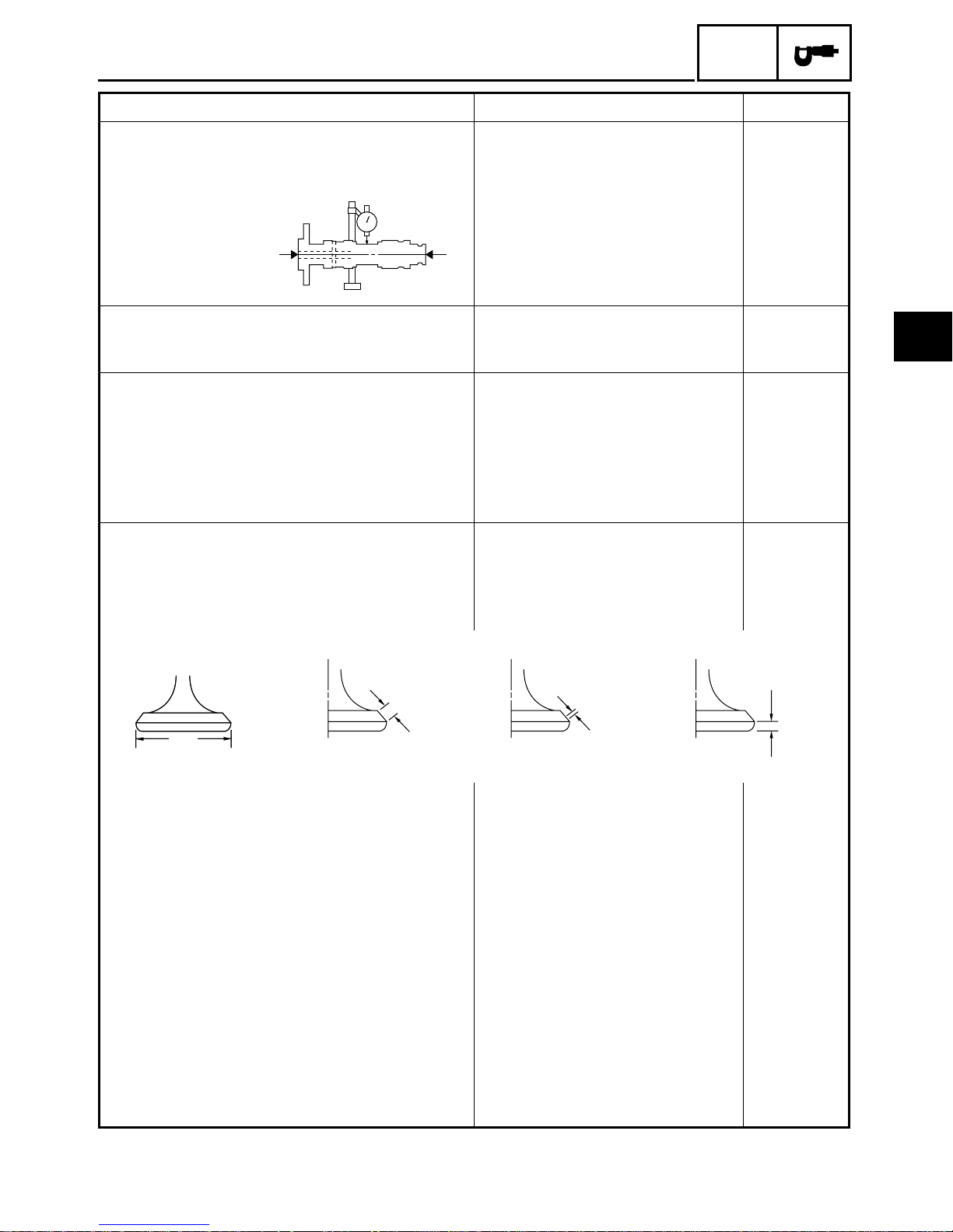
Camshaft:
Drive method Chain drive (Left) ---Cam cap inside diameter 25.000 ~ 25.033 mm
(0.9843 ~ 0.9855 in)
Camshaft outside diameter 24.96 ~ 24.98 mm
(0.9827 ~ 0.9835 in)
Shaft-to-cap clearance 0.020 ~ 0.073 mm
(0.0008 ~ 0.0029 in)
Cam dimensions
C
A
B
Intake “A” 36.537 ~ 36.637 mm
(1.438 ~ 1.442 in)
“B” 30.131 ~ 30.231 mm
(1.186 ~ 1.190 in)
“C” 6.527 ~ 6.647 mm
(0.257 ~ 0.262 in)
Exhaust “A” 36.582 ~ 36.682 mm
(1.440 ~ 1.444 in)
“B” 30.252 ~ 30.352 mm
(1.191 ~ 1.195 in)
----
----
----
36.437 mm
(1.435 in)
30.031 mm
(1.182 in)
----
36.482 mm
(1.436 in)
30.152 mm
(1.187 in)
2 - 4
MAINTENANCE SPECIFICATIONS
Item Standard Limit
“C” 6.572 ~ 6.692 mm
(0.259 ~ 0.263 in)
Camshaft runout limit ---- 0.03 mm
Cam chain:
Cam chain type / No. of links DID25SH/104 ---Cam chain adjustment method Automatic ----
Rocker arm / rocker arm shaft:
Rocker arm inside diameter 12.000 ~ 12.018 mm
(0.4724 ~ 0.4731 in)
Shaft outside diameter 11.981 ~ 11.991 mm
(0.4717 ~ 0.4721 in)
Arm-to-shaft clearance 0.009 ~ 0.037 mm
(0.0004 ~ 0.0015 in)
Valve, valve seat, valve guide:
Valve clearance (cold) IN 0.05 ~ 0.09 mm
(0.002 ~ 0.004 in)
EX 0.11 ~ 0.15 mm
(0.004 ~ 0.006 in)
Valve dimensions:
SPEC
----
(0.0012 in)
----
----
----
----
2
EX.
"B"
"A"
"A"
Head Dia
“A” head diameter IN 33.9 ~ 34.1 mm
“B” face width IN 1.7 ~ 2.8 mm (0.067 ~ 0.110 in) ----
“C” seat width IN 0.9 ~ 1.1 mm (0.035 ~ 0.043 in) 1.6 mm
“D” margin thickness IN 0.8 ~ 1.2 mm (0.032 ~ 0.047 in) ----
Stem outside diameter IN 5.975 ~ 5.990 mm
Face Width
EX 28.4 ~ 28.6 mm
EX 1.7 ~ 2.8 mm (0.067 ~ 0.110 in) ----
EX 0.9 ~ 1.1 mm (0.035 ~ 0.043 in) 1.6 mm
EX 0.8 ~ 1.2 mm (0.032 ~ 0.047 in) ----
EX 5.960 ~ 5.975 mm
Seat Width
(1.335 ~ 1.343 in)
(1.118 ~ 1.126 in)
(0.2352 ~ 0.2358 in)
(0.2346 ~ 0.2352 in)
"C"
Margin Thickness
----
----
(0.063 in)
(0.063 in)
----
----
"D"
2 - 5
2
MAINTENANCE SPECIFICATIONS
Item Standard Limit
Guide inside diameter IN 6.000~ 6.012mm
(0.236 ~ 0.237 in)
EX 6.000~ 6.012mm
(0.236 ~ 0.237 in)
Stem-to-guide clearance IN 0.010 ~ 0.037 mm
(0.0004 ~ 0.0015 in)
EX 0.025 ~ 0.052 mm
(0.001 ~ 0.002 in)
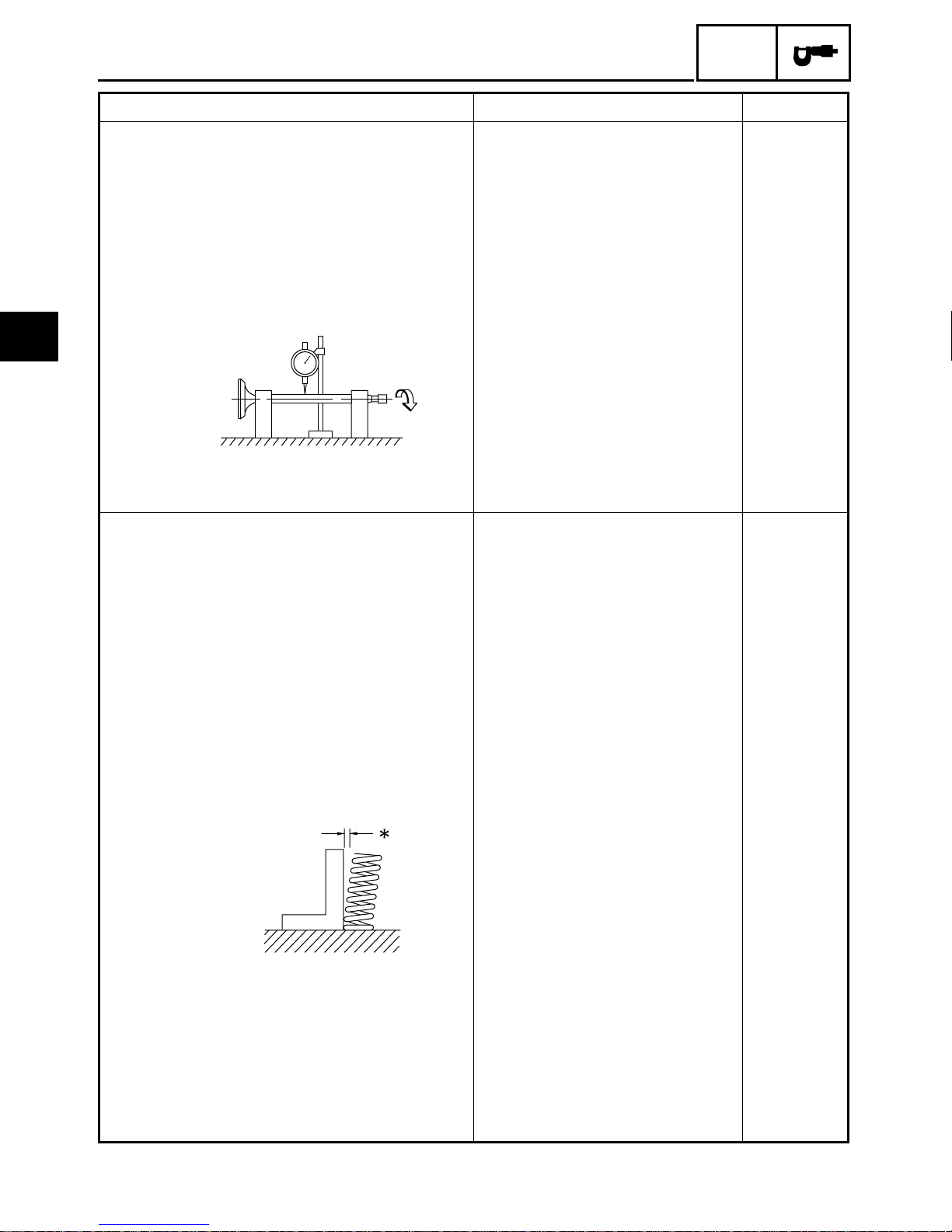
Stem runout limit ---- 0.03 mm
Valve seat width IN 0.9 ~ 1.1 mm (0.035 ~ 0.043 in) ----
EX 0.9 ~ 1.1 mm (0.035 ~ 0.043 in) ----
Valve spring:
Inner spring:
Free length IN 35.5 mm (1.4 in) ----
EX 35.5 mm (1.4 in) ----
Set length (valve closed) IN 30.5 mm (1.2 in) ----
EX 30.5 mm (1.2 in) ----
Compressed pressure
(installed) IN 82.4 ~ 100.0 N
(8.4 ~ 10.2 kg, 18.5 ~ 22.5 lb)
EX 82.4 ~ 100.0 N
(8.4 ~ 10.2 kg, 18.5 ~ 22.5 lb)
Tilt limit IN 2.5˚/ 1.6 mm
*
EX 2.5˚/ 1.6 mm
SPEC
----
----
0.08 mm
(0.0031 in)
0.10 mm
(0.0039 in)
(0.0012 in)
----
----
(2.5˚/0.06 in)
(2.5˚/0.06 in)
Direction of winding
(top view) IN Counterclockwise ----
Outer spring:
Free length IN 37.2 mm (1.46 in) ----
Set length (valve closed) IN 32.0 mm (1.26 in) ----
EX Counterclockwise ----
EX 37.2 mm (1.46 in) ----
EX 32.0 mm (1.26 in) ----
2 - 6
 Loading...