


2011
SERVICE MANUAL
YFM125RA
2PA-28197-10LIT-11616-24-36

EAS20050
YFM125RA
SERVICE MANUAL
©2010 by Yamaha Motor Corporation, U.S.A.
First edition, May 2010
All rights reserved.
Any reproduction or unauthorized use
without the written permission of
Yamaha Motor Corporation, U.S.A.
is expressly prohibited.
Printed in U.S.A.
P/N LIT-11616-24-36
EAS20071
IMPORTANT
This manual was produced by the Yamaha Motor Company, Ltd. primarily for use by Yamaha dealers and their qualified mechanics. It is not possible to include all the knowledge of a mechanic in one
manual. Therefore, anyone who uses this book to perform maintenance and repairs on Yamaha
vehicles should have a basic understanding of mechanics and the techniques to repair these types
of vehicles. Repair and maintenance work attempted by anyone without this knowledge is likely to
render the vehicle unsafe and unfit for use.
This model has been designed and manufactured to perform within certain specifications in regard
to performance and emissions. Proper service with the correct tools is necessary to ensure that the
vehicle will operate as designed. If there is any question about a service procedure, it is imperative
that you contact a Yamaha dealer for any service information changes that apply to this model. This
policy is intended to provide the customer with the most satisfaction from his vehicle and to conform
to federal environmental quality objectives.
Yamaha Motor Company, Ltd. is continually striving to improve all of its models. Modifications and
significant changes in specifications or procedures will be forwarded to all authorized Yamaha dealers and will appear in future editions of this manual where applicable.
TIP
• This Service Manual contains information regarding periodic maintenance to the emission control
system. Please read this material carefully.
• Designs and specifications are subject to change without notice.
EAS20081
IMPORTANT MANUAL INFORMATION
Particularly important information is distinguished in this manual by the following notations.
This is the safety alert symbol. It is used to alert you to potential personal injury hazards. Obey all safety messages that follow this symbol
to avoid possible injury or death.
A WARNING indicates a hazardous situation which, if not avoided,
WARNING
NOTICE
TIP
could result in death or serious injury.
A NOTICE indicates special precautions that must be taken to avoid
damage to the vehicle or other property.
A TIP provides key information to make procedures easier or clearer.
EAS20091
HOW TO USE THIS MANUAL
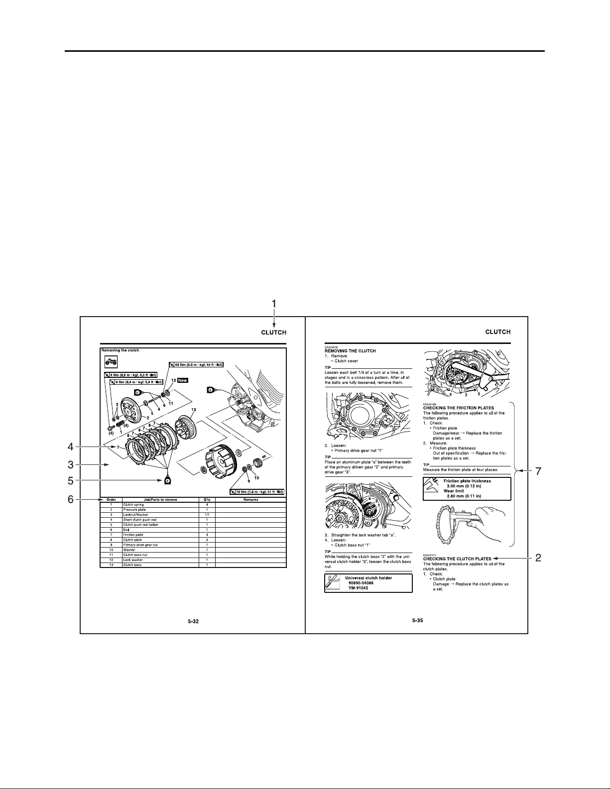
This manual is intended as a handy, easy-to-read reference book for the mechanic. Comprehensive
explanations of all installation, removal, disassembly, assembly, repair and check procedures are
laid out with the individual steps in sequential order.
• The manual is divided into chapters and each chapter is divided into sections. The current section
title “1” is shown at the top of each page.
• Sub-section titles “2” appear in smaller print than the section title.
• To help identify parts and clarify procedure steps, there are exploded diagrams “3” at the start of
each removal and disassembly section.
• Numbers “4” are given in the order of the jobs in the exploded diagram. A number indicates a disassembly step.
• Symbols “5” indicate parts to be lubricated or replaced.
Refer to “SYMBOLS”.
• A job instruction chart “6” accompanies the exploded diagram, providing the order of jobs, names
of parts, notes in jobs, etc.
• Jobs “7” requiring more information (such as special tools and technical data) are described
sequentially.
EAS30370
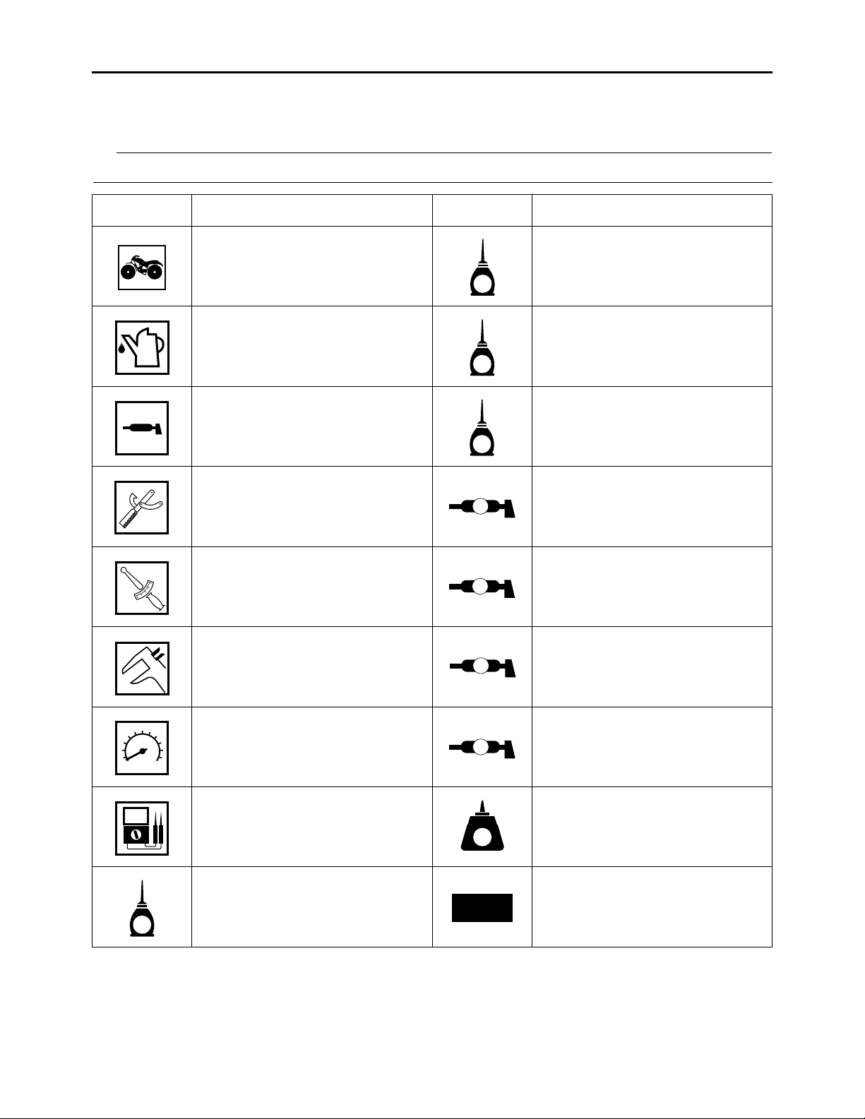
SYMBOLS
The following symbols are used in this manual for easier understanding.
TIP
The following symbols are not relevant to every vehicle.
SYMBOL DEFINITION SYMBOL DEFINITION
Serviceable with engine
mounted
G
Gear oil
Filling fluid Molybdenum disulfide oil
M
Lubricant Brake fluid
BF
Special tool Wheel bearing grease
T
.
R
.
Tightening torque Lithium-soap-based grease
Wear limit, clearance Molybdenum disulfide grease
B
LS
M
Engine speed Silicone grease
Electrical data
Engine oil
E
S
LT
New
Apply locking agent (LOCTITE®).
Replace the part with a new
one.

EAS20110
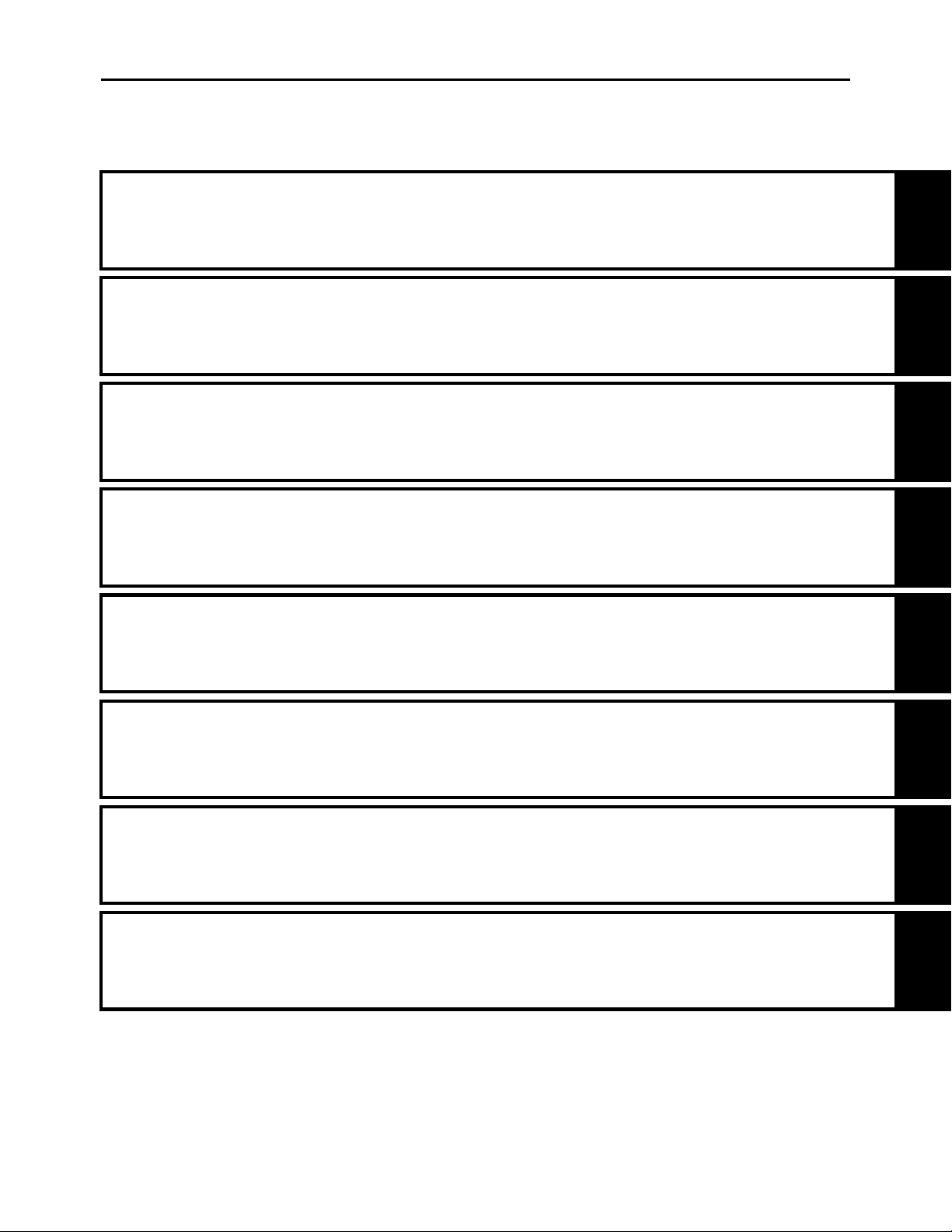
TABLE OF CONTENTS
GENERAL INFORMATION
SPECIFICATIONS
PERIODIC CHECKS AND ADJUSTMENTS
CHASSIS
ENGINE
1
2
3
4
5
FUEL SYSTEM
ELECTRICAL SYSTEM
TROUBLESHOOTING
6
7
8


GENERAL INFORMATION
IDENTIFICATION.......................................................................................... 1-1
VEHICLE IDENTIFICATION NUMBER...................................................1-1
MODEL LABEL .......................................................................................1-1
IMPORTANT INFORMATION .......................................................................1-2
PREPARATION FOR REMOVAL AND DISASSEMBLY..........................1-2
REPLACEMENT PARTS.........................................................................1-2
GASKETS, OIL SEALS AND O-RINGS..................................................1-2
LOCK WASHERS/PLATES AND COTTER PINS ...................................1-2
BEARINGS AND OIL SEALS .................................................................1-3
CIRCLIPS ............................................................................................... 1-3
BASIC SERVICE INFORMATION................................................................. 1-4
QUICK FASTENERS ..............................................................................1-4
ELECTRICAL SYSTEM ..........................................................................1-5
SPECIAL TOOLS..........................................................................................1-9
1

EAS20130
IDENTIFICATION
EAS20140
VEHICLE IDENTIFICATION NUMBER
The vehicle identification number “1” is
stamped into the left side of the frame.
EAS20150
MODEL LABEL
The model label “1” is affixed to the air filter
case cover. This information will be needed to
order spare parts.
IDENTIFICATION
1-1
EAS20180
IMPORTANT INFORMATION
EAS20190
PREPARATION FOR REMOVAL AND DISASSEMBLY
1. Before removal and disassembly, remove
all dirt, mud, dust and foreign material.
2. Use only the proper tools and cleaning
equipment.
Refer to “SPECIAL TOOLS” on page 1-9.
3. When disassembling, always keep mated
parts together. This includes gears, cylinders, pistons and other parts that have
been “mated” through normal wear. Mated
parts must always be reused or replaced
as an assembly.
IMPORTANT INFORMATION
EAS20210
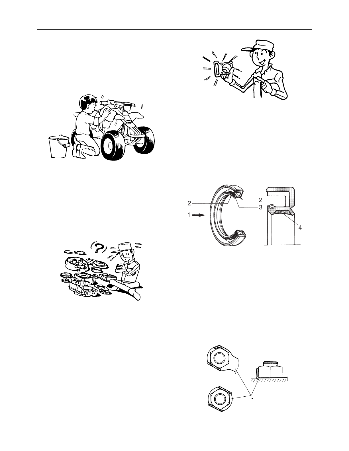
GASKETS, OIL SEALS AND O-RINGS
1. When overhauling the engine, replace all
gaskets, seals and O-rings. All gasket surfaces, oil seal lips and O-rings must be
cleaned.
2. During reassembly, properly oil all mating
parts and bearings and lubricate the oil
seal lips with grease.
4. During disassembly, clean all of the parts
and place them in trays in the order of disassembly. This will speed up assembly and
allow for the correct installation of all parts.
5. Keep all parts away from any source of fire.
EAS20200
REPLACEMENT PARTS
Use only genuine Yamaha parts for all replacements. Use oil and grease recommended by
Yamaha for all lubrication jobs. Other brands
may be similar in function and appearance, but
inferior in quality.
1. Oil
2. Lip
3. Spring
4. Grease
EAS20220
LOCK WASHERS/PLATES AND COTTER
PINS
After removal, replace all lock washers/plates
“1” and cotter pins. After the bolt or nut has
been tightened to specification, bend the lock
tabs along a flat of the bolt or nut.
1-2

EAS20231
BEARINGS AND OIL SEALS
Install bearings “1” and oil seals “2” so that the
manufacturer marks or numbers are visible.
When installing oil seals, lubricate the oil seal
lips with a light coat of lithium-soap-based
grease. Oil bearings liberally when installing, if
appropriate.
ECA13300
Do not spin the bearing with compressed
air because this will damage the bearing
surfaces.
IMPORTANT INFORMATION
EAS20240
CIRCLIPS
Before reassembly, check all circlips carefully
and replace damaged or distorted circlips.
Always replace piston pin clips after one use.
When installing a circlip “1”, make sure the
sharp-edged corner “2” is positioned opposite
the thrust “3” that the circlip receives.
1-3
EAS30380
BASIC SERVICE INFORMATION
EAS30390
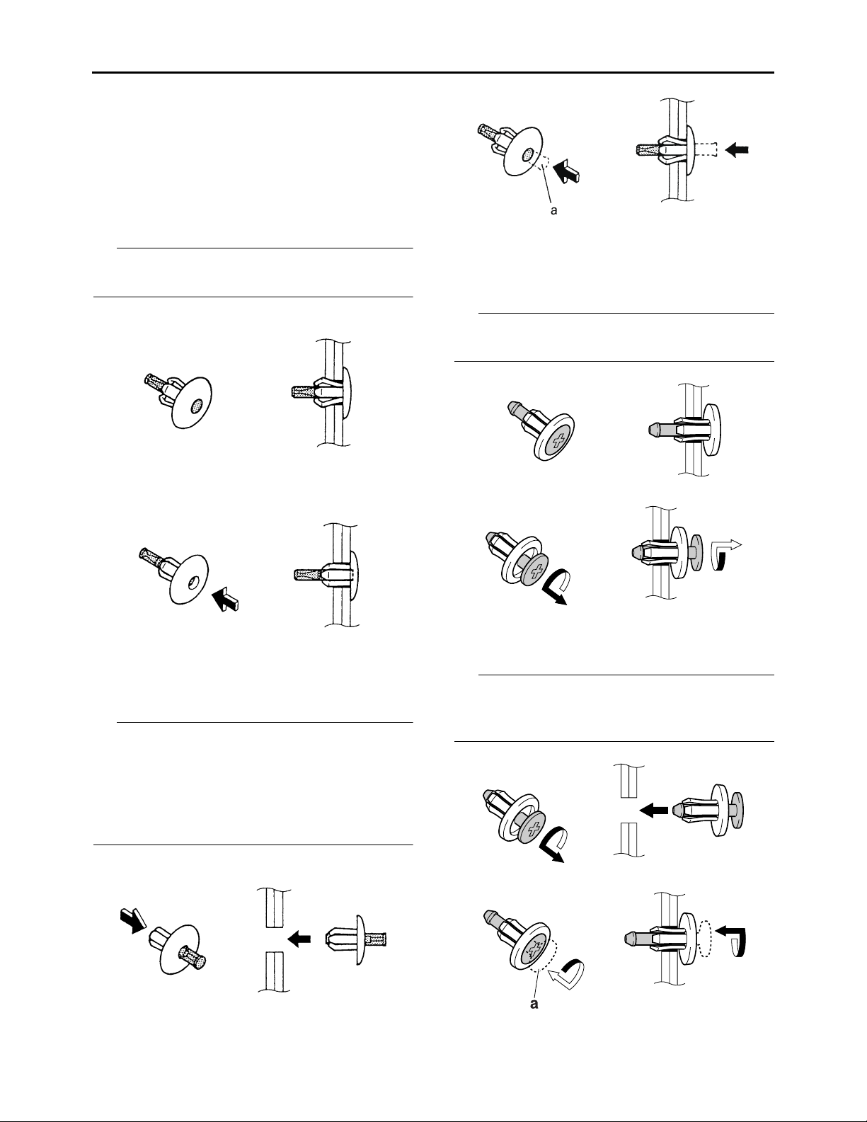
QUICK FASTENERS
Rivet type
1. Remove:
• Quick fastener
TIP
To remove the quick fastener, push its pin with
a screwdriver, then pull the fastener out.
BASIC SERVICE INFORMATION
Screw type
1. Remove:
• Quick fastener
TIP
To remove the quick fastener, loosen the screw
with a screwdriver, then pull the fastener out.
2. Install:
• Quick fastener
TIP
To install the quick fastener, push its pin so that
it protrudes from the fastener head, then insert
the fastener into the part to be secured and
push the pin “a” in with a screwdriver. Make
sure that the pin is flush with the fastener’s
head.
2. Install:
• Quick fastener
TIP
To install the quick fastener, insert the fastener
into the part to be secured and tighten the
screw “a”.
1-4

BASIC SERVICE INFORMATION
EAS30402
ELECTRICAL SYSTEM
Electrical parts handling
ECA16600
Never disconnect a battery lead while the
engine is running; otherwise, the electrical
components could be damaged.
ECA16751
When disconnecting the battery leads from
the battery, be sure to disconnect the negative battery lead first, then the positive battery lead. If the positive battery lead is
disconnected first and a tool or similar item
contacts the vehicle, a spark could be generated, which is extremely dangerous.
ECA16760
Be sure to connect the battery leads to the
correct battery terminals. Reversing the
battery lead connections could damage the
electrical components.
ECA16771
When connecting the battery leads to the
battery, be sure to connect the positive battery lead first, then the negative battery
lead. If the negative battery lead is connected first and a tool or similar item contacts the vehicle while the positive battery
lead is being connected, a spark could be
generated, which is extremely dangerous.
TIP
If a battery lead is difficult to disconnect due to
rust on the battery terminal, remove the rust
using hot water.
ECA16610
Turn the main switch to “OFF” before disconnecting or connecting an electrical
component.
1-5

BASIC SERVICE INFORMATION
ECA16620
Handle electrical components with special
care, and do not subject them to strong
shocks.
ECA16630
Electrical components are very sensitive to
and can be damaged by static electricity.
Therefore, never touch the terminals and be
sure to keep the contacts clean.
Checking the electrical system
TIP
Before checking the electrical system, make
sure that the battery voltage is at least 12 V.
ECA14371
Never insert the tester probes into the coupler terminal slots. Always insert the
probes from the opposite end “a” of the
coupler, taking care not to loosen or damage the leads.
TIP
When resetting the CDI Unit by turning the
main switch to “OFF”, be sure to wait approximately 5 seconds before turning the main
switch back to “ON”.
a
ECA16640
For waterproof couplers, never insert the
tester probes directly into the coupler.
When performing any checks using a
waterproof coupler, use the specified test
harness or a suitable commercially available test harness.
1-6

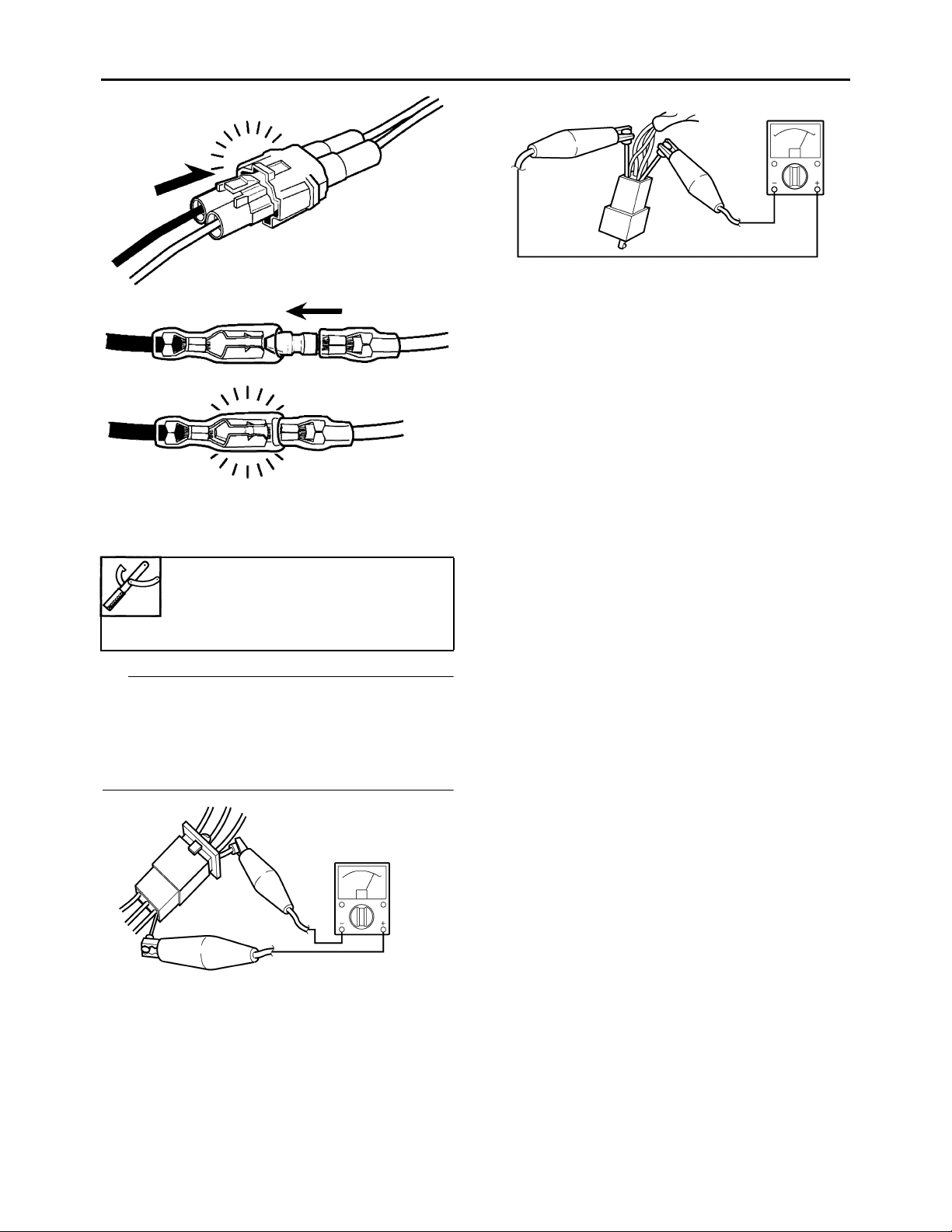
Checking the connections
Check the leads, couplers, and connectors for
stains, rust, moisture, etc.
1. Disconnect:
• Lead
• Coupler
• Connector
ECA16780
• When disconnecting a coupler, release
the coupler lock, hold both sections of
the coupler securely, and then disconnect
the coupler.
• There are many types of coupler locks;
therefore, be sure to check the type of
coupler lock before disconnecting the
coupler.
BASIC SERVICE INFORMATION
3. Check:
• All connections
Loose connection → Connect properly.
TIP
• If the pin “1” on the terminal is flattened,
bend it up.
• After disassembling and assembling a coupler, pull on the leads to make sure that they
are installed securely.
ECA16790
When disconnecting a connector, do not
pull the leads. Hold both sections of the
connector securely, and then disconnect
the connector.
2. Check:
• Lead
• Coupler
• Connector
Moisture → Dry with an air blower.
Rust/stains → Connect and disconnect
several times.
1
4. Connect:
• Lead
• Coupler
• Connector
TIP
• When connecting a coupler or connector,
push both sections of the coupler or connector together until they are connected
securely.
• Make sure all connections are tight.
1-7
BASIC SERVICE INFORMATION
5. Check:
•Continuity
(with the pocket tester)
Pocket tester
90890-03112
Analog pocket tester
YU-03112-C
TIP
• If there is no continuity, clean the terminals.
• When checking the wire harness, perform
steps (1) to (3).
• As a quick remedy, use a contact revitalizer
available at most part stores.
1-8

SPECIAL TOOLS
EAS20260
SPECIAL TOOLS
The following special tools are necessary for complete and accurate tune-up and assembly. Use
only the appropriate special tools as this will help prevent damage caused by the use of inappropriate tools or improvised techniques. Special tools, part numbers or both may differ depending on the
country.
When placing an order, refer to the list provided below to avoid any mistakes.
TIP
• For U.S.A. and Canada, use part number starting with “YM-”, “YU-”, or “ACC-”.
• For others, use part number starting with “90890-”.
Tool name/Tool No. Illustration
Slide hammer bolt
90890-01083
Slide hammer bolt 6 mm
YU-01083-1
Weight
90890-01084
YU-01083-3
Crankcase separating tool
90890-01135
Crankcase separator
YU-01135-B
Reference
pages
5-14, 5-16
5-14
5-64
Ring nut wrench
90890-01268
Spanner wrench
YU-01268
3-18
1-9
SPECIAL TOOLS
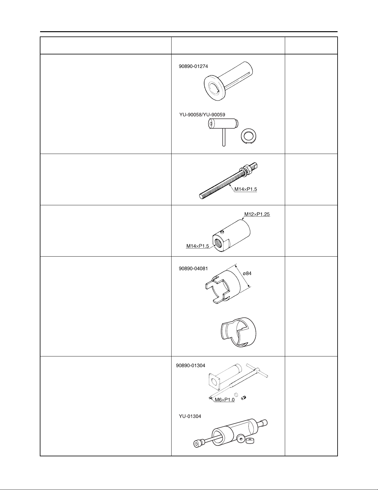
Tool name/Tool No. Illustration
Crankshaft installer pot
90890-01274
Installing pot
YU-90058
Crankshaft installer bolt
90890-01275
Bolt
YU-90060
Adapter (M12)
90890-01278
Adapter #3
YU-90063
Reference
pages
5-65
5-65
5-65
Spacer (crankshaft installer)
90890-04081
Pot spacer
YM-91044
Piston pin puller set
90890-01304
Piston pin puller
YU-01304
5-65
YM-91044
5-27
1-10

SPECIAL TOOLS
Tool name/Tool No. Illustration
Tappet adjusting tool
90890-01311
Six piece tappet set
YM-A5970
Flywheel puller
90890-01362
Heavy duty puller
YU-33270-B
Sheave holder
90890-01701
Primary clutch holder
YS-01880-A
Reference
pages
3-6
5-50
5-50, 5-51, 5-52
Thickness gauge
90890-03180
Feeler gauge set
YU-26900-9
Digital circuit tester
90890-03174
Model 88 Multimeter with tachometer
YU-A1927
Pocket tester
90890-03112
Analog pocket tester
YU-03112-C
Carburetor angle driver
90890-03158
3-5, 5-36
5-56
1-8, 7-31, 7-32,
7-33, 7-37, 738, 7-39, 7-40,
7-41, 7-42
3-7
1-11

SPECIAL TOOLS
Tool name/Tool No. Illustration
Valve spring compressor
90890-04019
YM-04019
Valve spring compressor attachment
90890-04114
Valve spring compressor adapter 19.5 mm
YM-04114
Fuel level gauge
90890-01312
YM-01312-A
Universal clutch holder
90890-04086
YM-91042
Reference
pages
5-19, 5-24
5-19, 5-24
6-10
5-35, 5-38
Valve guide remover (ø5)
90890-04097
Valve guide remover (5.0 mm)
YM-04097
Valve guide installer (ø5)
90890-04098
Valve guide installer (5.0 mm)
YM-04098
Valve guide reamer (ø5)
90890-04099
Valve guide reamer (5.0 mm)
YM-04099
5-21
5-21
5-21
1-12

SPECIAL TOOLS
Tool name/Tool No. Illustration
Valve lapper
90890-04101
Valve lapping tool
YM-A8998
Axle nut wrench (46 mm)
90890-01498
Rear axle nut wrench 46 mm
YM-37134
Ignition checker
90890-06754
Opama pet-4000 spark checker
YM-34487
Reference
pages
5-22
4-14, 4-15
7-39
Digital tachometer
90890-06760
YU-39951-B
Yamaha bond No. 1215
(Three bond No.1215®)
90890-85505
3-6, 7-41
5-52, 5-61, 5-62
1-13

SPECIFICATIONS
GENERAL SPECIFICATIONS...................................................................... 2-1
ENGINE SPECIFICATIONS..........................................................................2-4
CHASSIS SPECIFICATIONS........................................................................ 2-9
ELECTRICAL SPECIFICATIONS...............................................................2-11
TIGHTENING TORQUES............................................................................ 2-13
GENERAL TIGHTENING TORQUE SPECIFICATIONS.......................2-13
ENGINE TIGHTENING TORQUES ......................................................2-14
CHASSIS TIGHTENING TORQUES ....................................................2-16
LUBRICATION POINTS AND LUBRICANT TYPES..................................2-20
ENGINE ................................................................................................2-20
LUBRICATION SYSTEM CHART AND DIAGRAMS .................................2-21
ENGINE OIL LUBRICATION CHART ...................................................2-21
LUBRICATION DIAGRAMS ..................................................................2-23
2
CABLE ROUTING ......................................................................................2-27

GENERAL SPECIFICATIONS
EAS29110
GENERAL SPECIFICATIONS
Model
Model 2PA1 (USA)
Dimensions
Overall length 1610 mm (63.4 in)
Overall width 1018 mm (40.1 in)
Overall height 1010 mm (39.8 in)
Seat height 715 mm (28.1 in)
Wheelbase 1110 mm (43.7 in)
Ground clearance 85 mm (3.3 in)
Minimum turning radius 2900 mm (114 in)
Weight
With oil and fuel 136.0 kg (300 lb)
Engine
Engine type Air cooled 4-stroke, SOHC
Cylinder arrangement Forward-inclined single cylinder
Displacement 124 cm³
Bore × stroke 54.0 × 54.0 mm (2.13 × 2.13 in)
Compression ratio 10.0 : 1
Starting system Electric starter
Lubrication system Wet sump
Engine oil
Recommended brand YAMALUBE
Type SAE 5W-30, 10W-30, 10W-40, 15W-40, 20W-
Recommended engine oil grade API service SG type or higher, JASO standard
Engine oil quantity
Periodic oil change 1.25 L (1.32 US qt, 1.10 Imp.qt)
Total amount 1.50 L (1.59 US qt, 1.32 Imp.qt)
Oil filter
Oil filter type Centrifugal
Air filter
Air filter element Wet element
Air filter oil grade Yamaha foam air filter oil or equivalent oil
Fuel
Recommended fuel Unleaded gasoline only (USA, AUS, NZL)
Fuel tank capacity 9.0 L (2.38 US gal, 1.98 Imp.gal)
Fuel reserve amount 1.0 L (0.26 US gal, 0.22 Imp.gal)
Carburetor
Type × quantity BSR29 × 1
Spark plug
Manufacturer/model NGK/CR6HSA
Spark plug gap 0.6–0.7 mm (0.024–0.028 in)
2PA2 (CAN)
2PA3 (AUS, NZL)
40 or 20W-50
MA
Regular unleaded gasoline only (CAN)
2-1

GENERAL SPECIFICATIONS
Clutch
Type Wet, multiple-disc
Transmission
Primary reduction system Helical gear
Primary reduction ratio 68/20 (3.400)
Secondary reduction system Chain drive
Secondary reduction ratio 48/14 (3.429)
Transmission type Constant mesh 5-speed
Operation Left foot operation
1st 37/14 (2.643)
2nd 32/18 (1.778)
3rd 25/19 (1.316)
4th 23/22 (1.045)
5th 21/24 (0.875)
Chassis
Frame type Steel tube frame
Caster angle 6°
Camber angle -1.5°
Kingpin angle 14.8°
Trail 23.0 mm (0.91 in)
Tread rear (STD) 791.0 mm (31.14 in)
Tread front (STD) 841.0 mm (33.11 in)
Toe-in (with tire touching the ground) 8.0–18.0 mm (0.31–0.71 in)
Front tire
Type Tubeless
Size AT19 × 6-10
Manufacturer/model MAXXIS/M957Y
Wear limit 3.0 mm (0.12 in)
Rear tire
Type Tubeless
Size AT18 × 9-8
Manufacturer/model MAXXIS/M940
Wear limit 3.0 mm (0.12 in)
Tire air pressure (measured on cold tires)
Maximum loading limit 100.0 kg (220 lb)
Recommended
Front 25.0 kPa (0.25 kgf/cm², 3.6 psi)
Rear 30.0 kPa (0.30 kgf/cm², 4.4 psi)
Minimum
Front 22.0 kPa (0.22 kgf/cm², 3.2 psi)
Rear 27.0 kPa (0.27 kgf/cm², 4.0 psi)
Front brake
Type Dual disc brake
Operation Right hand operation
Rear brake
Type Single disc brake
Operation Right foot operation
Front suspension
Type Double wishbone
2-2

GENERAL SPECIFICATIONS
Spring/shock absorber type Coil spring/oil damper
Wheel travel 190 mm (7.5 in)
Rear suspension
Type Swingarm
Spring/shock absorber type Coil spring/gas-oil damper
Wheel travel 200 mm (7.9 in)
Electrical system
Ignition system CDI
Charging system AC magneto
Battery
Model YTZ7S
Voltage, capacity 12 V, 6.0 Ah
Manufacturer GS YUASA
Ten hour rate amperage 0.6 A
Headlight
Bulb type Halogen bulb
Bulb voltage, wattage × quantity
Headlight 12 V, 35.0/36.5 W × 1
Tail/brake light 12 V, 5.0/21.0 W × 1
Neutral indicator light 12 V, 1.7 W × 1
2-3
ENGINE SPECIFICATIONS
EAS29120
ENGINE SPECIFICATIONS
Cylinder head
Volume 15.20–15.60 cm³ (0.93–0.95 cu.in)
Warpage limit 0.03 mm (0.0012 in)
Cylinder
Bore 54.024–54.056 mm (2.1269–2.1282 in)
Wear limit 54.156 mm (2.1321 in)
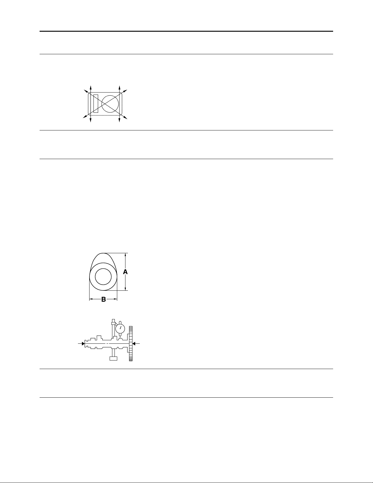
Camshaft
Drive system Chain drive (left)
Camshaft lobe dimensions
Intake A 25.881–25.981 mm (1.0189–1.0229 in)
Limit 25.851 mm (1.0178 in)
Intake B 21.194–21.294 mm (0.8344–0.8383 in)
Limit 21.165 mm (0.8333 in)
Exhaust A 25.841–25.941 mm (1.0174–1.0213 in)
Limit 25.811 mm (1.0162 in)
Exhaust B 20.997–21.097 mm (0.8267–0.8306 in)
Limit 20.967 mm (0.8255 in)
Camshaft runout limit 0.030 mm (0.0012 in)
Timing chain
Model/number of links 92RH2005-90M/90
Tensioning system Automatic
Rocker arm/rocker arm shaft
Rocker arm inside diameter 10.000–10.015 mm (0.3937–0.3943 in)
Limit 10.030 mm (0.3949 in)
Rocker arm shaft outside diameter 9.981–9.991 mm (0.3930–0.3933 in)
Limit 9.950 mm (0.3917 in)
Rocker-arm-to-rocker-arm-shaft clearance 0.009–0.034 mm (0.0004–0.0013 in)
Limit 0.08 mm (0.0031 in)
2-4

ENGINE SPECIFICATIONS
Valve, valve seat, valve guide
Valve clearance (cold)
Intake 0.08–0.12 mm (0.0032–0.0047 in)
Exhaust 0.10–0.14 mm (0.0039–0.0055 in)
Valve dimensions
Valve head diameter A (intake) 25.90–26.10 mm (1.0197–1.0276 in)
Valve head diameter A (exhaust) 21.90–22.10 mm (0.8622–0.8701 in)
Valve face width B (intake) 1.10–3.00 mm (0.0433–0.1181 in)
Valve face width B (exhaust) 1.70–2.80 mm (0.0669–0.1102 in)
Valve seat width C (intake) 0.90–1.10 mm (0.0354–0.0433 in)
Limit 1.60 mm (0.06 in)
Valve seat width C (exhaust) 0.90–1.10 mm (0.0354–0.0433 in)
Limit 1.60 mm (0.06 in)
Valve margin thickness D (intake) 0.40–0.80 mm (0.0157–0.0315 in)
Valve margin thickness D (exhaust) 0.80–1.20 mm (0.0315–0.0472 in)
Valve stem diameter (intake) 4.975–4.990 mm (0.1959–0.1965 in)
Limit 4.950 mm (0.1949 in)
Valve stem diameter (exhaust) 4.960–4.975 mm (0.1953–0.1959 in)
Limit 4.935 mm (0.1943 in)
Valve guide inside diameter (intake) 5.000–5.012 mm (0.1969–0.1973 in)
Limit 5.042 mm (0.1985 in)
Valve guide inside diameter (exhaust) 5.000–5.012 mm (0.1969–0.1973 in)
Limit 5.042 mm (0.1985 in)
Valve-stem-to-valve-guide clearance (intake) 0.010–0.037 mm (0.0004–0.0015 in)
Limit 0.080 mm (0.0032 in)
Valve-stem-to-valve-guide clearance
(exhaust) 0.025–0.052 mm (0.0010–0.0020 in)
Limit 0.100 mm (0.0039 in)
Valve stem runout limit 0.010 mm (0.0004 in)
Cylinder head valve seat width (intake) 0.90–1.10 mm (0.0354–0.0433 in)
Limit 1.60 mm (0.06 in)
Cylinder head valve seat width (exhaust) 0.90–1.10 mm (0.0354–0.0433 in)
Limit 1.60 mm (0.06 in)
Valve spring
Free length (intake) 47.06 mm (1.85 in)
Limit 44.71 mm (1.76 in)
2-5
ENGINE SPECIFICATIONS
Free length (exhaust) 47.06 mm (1.85 in)
Limit 44.71 mm (1.76 in)
Installed length (intake) 25.60 mm (1.01 in)
Installed length (exhaust) 25.60 mm (1.01 in)
Spring rate K1 (intake) 8.01 N/mm (0.82 kgf/mm, 45.74 lbf/in)
Spring rate K2 (intake) 9.33 N/mm (0.95 kgf/mm, 53.27 lbf/in)
Spring rate K1 (exhaust) 8.01 N/mm (0.82 kgf/mm, 45.74 lbf/in)
Spring rate K2 (exhaust) 9.33 N/mm (0.95 kgf/mm, 53.27 lbf/in)
Installed compression spring force (intake) 160.00–184.00 N (16.32–18.76 kgf, 35.97–
Installed compression spring force (exhaust) 160.00–184.00 N (16.32–18.76 kgf, 35.97–
Spring tilt (intake) 2.5°/2.1 mm (0.08 in)
Spring tilt (exhaust) 2.5°/2.1 mm (0.08 in)
Winding direction (intake) Clockwise
Winding direction (exhaust) Clockwise
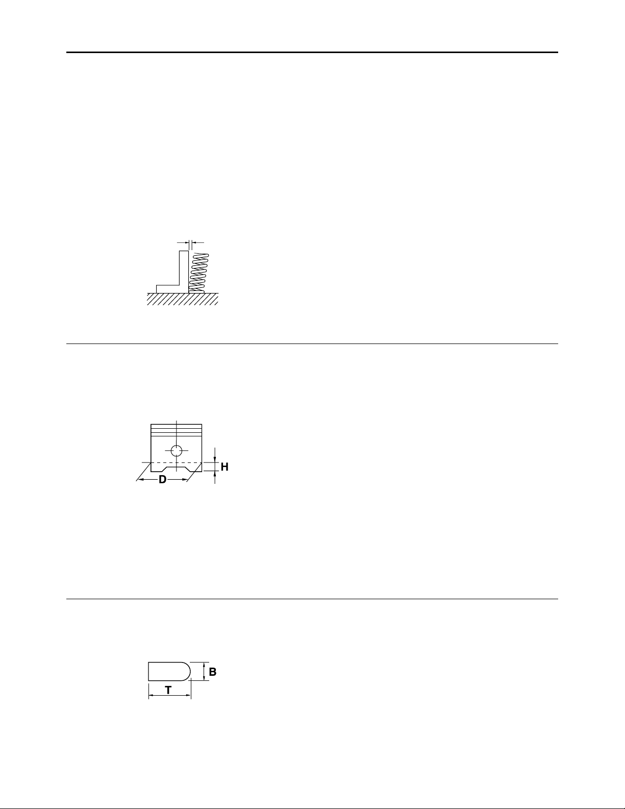
Piston
Piston-to-cylinder clearance 0.019–0.035 mm (0.0007–0.0014 in)
Limit 0.15 mm (0.006 in)
Diameter D 53.997–54.029 mm (2.1259–2.1271 in)
Height H 4.5 mm (0.18 in)
41.36 lbf)
41.36 lbf)
Offset 0.50 mm (0.0197 in)
Offset direction Intake side
Piston pin bore inside diameter 15.002–15.013 mm (0.5906–0.5911 in)
Limit 15.043 mm (0.5922 in)
Piston pin outside diameter 14.991–15.000 mm (0.5902–0.5906 in)
Limit 14.971 mm (0.5894 in)
Piston-pin-to-piston-pin-bore clearance 0.002–0.022 mm (0.0001–0.0009 in)
Limit 0.072 mm (0.0028 in)
Piston ring
Top ring
Ring type Barrel
Dimensions (B × T) 1.00 × 2.10 mm (0.04 × 0.08 in)
End gap (installed) 0.15–0.30 mm (0.006–0.012 in)
Limit 0.40 mm (0.0157 in)
Ring side clearance 0.035–0.070 mm (0.0014–0.0028 in)
Limit 0.120 mm (0.0047 in)
2-6
ENGINE SPECIFICATIONS
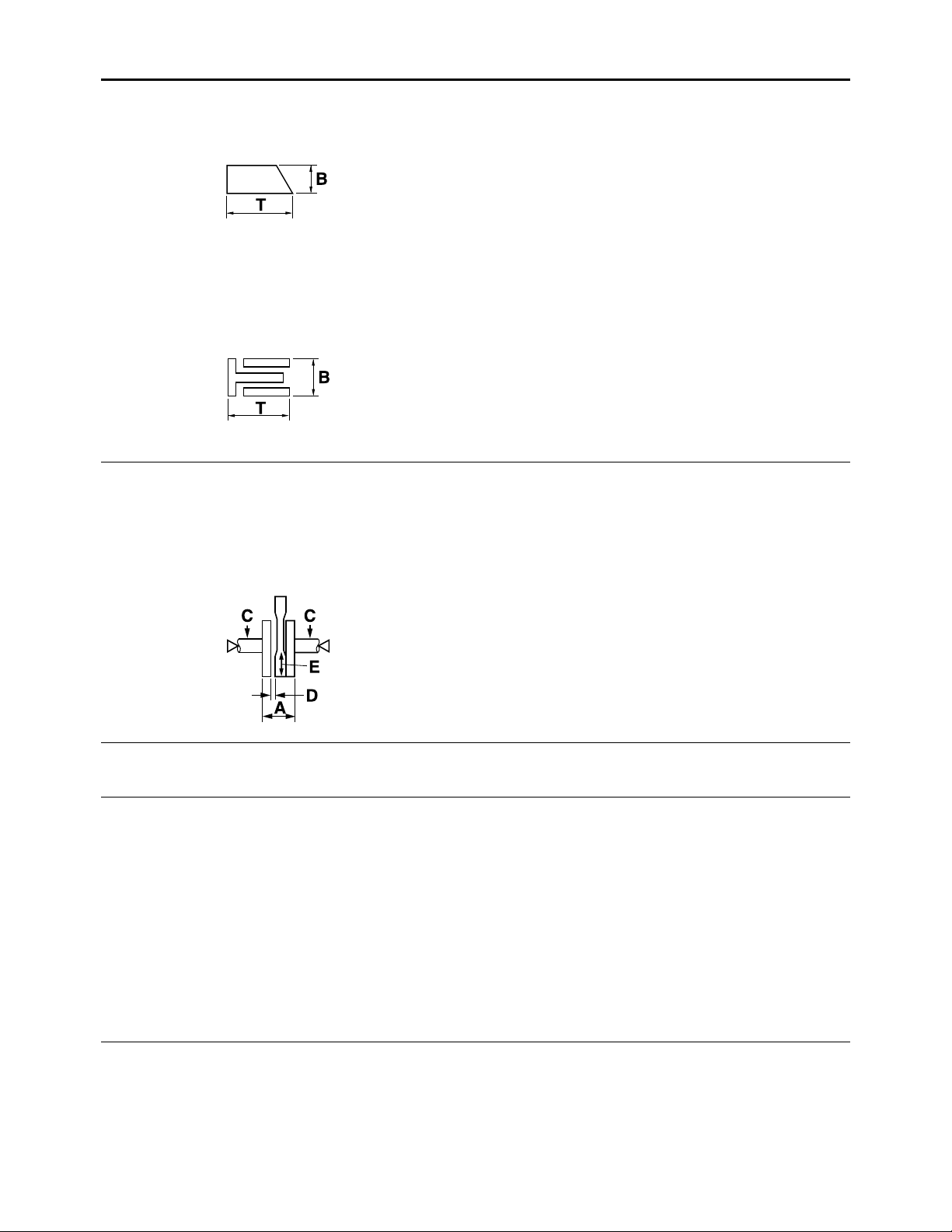
2nd ring
Ring type Taper
Dimensions (B × T) 1.00 × 2.10 mm (0.04 × 0.08 in)
End gap (installed) 0.30–0.45 mm (0.012–0.018 in)
Limit 0.55 mm (0.0217 in)
Ring side clearance 0.020–0.060 mm (0.0008–0.0024 in)
Limit 0.120 mm (0.0047 in)
Oil ring
Dimensions (B × T) 2.00 × 2.25 mm (0.08 × 0.09 in)
End gap (installed) 0.20–0.70 mm (0.008–0.028 in)
Crankshaft
Width A 46.95–47.00 mm (1.848–1.850 in)
Runout limit C 0.030 mm (0.0012 in)
Big end side clearance D 0.15–0.45 mm (0.0059–0.0177 in)
Limit 0.50 mm (0.0197 in)
Big end radial clearance E 0.010–0.021 mm (0.0004–0.0008 in)
Balancer
Balancer drive method Gear
Clutch
Friction plate thickness 3.00 mm (0.12 in)
Wear limit 2.80 mm (0.11 in)
Plate quantity 4 pcs
Clutch plate thickness 1.60 mm (0.06 in)
Plate quantity 3 pcs
Clutch plate warpage limit 0.05 mm (0.0020 in)
Clutch spring free length 31.7 mm (1.25 in)
Limit 30.1 mm (1.19 in)
Spring quantity 4 pcs
Clutch release method Inner push, cam push
Push rod bending limit 0.5 mm (0.02 in)
Transmission
Main axle runout limit 0.03 mm (0.0012 in)
Drive axle runout limit 0.03 mm (0.0012 in)
Main axle assembly width 83.25–83.45 mm (3.278–3.285 in)
2-7
 Loading...