

Yamaha VX500SXBC, VX700ERC Service Manual

SUPPLEMENTARY SERVICE MANUAL
CAUTION:
NOTE:
FOREWORD
This Supplementary Service Manual has
been prepared to introduce new service and
new data for the VX500SXBC, VX700ERC.
For complete information, on service procedures, it is necessary to use this Supplementary Service Manual together with following
manual:
VT500A, VT600A, MM600A, MM700A
VX500XTA/ XTCA/XTCEA /XTCRA
VX600XTA/XTCA/XTCEA/XTCRA/SXA
VX700SXA
SERVICE MANUAL:
8CY-28197-10 (LIT-12618-01-83)
OE001
NOTICE
This manual was written by the Yamaha Motor Company primarily for use by Yamaha
dealers and their qualified mechanics. It is
not possible to put an entire mechanic’s
education into one manual, so it is assumed
that persons using this book to perform
maintenance and repairs on Yamaha snowmobiles have a basic understanding of the
mechanical concepts and procedures inherent in snowmobile repair. Without such
knowledge, attempted repairs or service to
this model may render it unfit to use and/or
unsafe.
Yamaha Motor Company, Ltd. is continually
striving to improve all models manufactured by Yamaha. Modifications and significant changes in specifications or procedures
will be forwarded to all Authorized Yamaha
dealers and will, where applicable, appear in
future editions of this manual.
OE022
VX500SXBC
VX700ERC
SUPPLEMENTARY SERVICE MANUAL
1998 by Yamaha Motor Corporation, U.S.A.
1st Edition, March 1998
All rights reserved. Any reprinting or
unauthorized use without the written
permission of Yamaha Motor Corporation,
U.S.A. is expressly prohibited.
Printed in U.S.A.
OE011
HOW TO USE THIS MANUAL
Particularly important information is distinguished in this manual by the following
notations:
The Safety Alert Symbol means ATTENTION! BE ALERT!
YOUR SAFETY IS INVOLVED!
Failure to follow WARNING instructions
could result in severe injury or death
to the
snowmobile operator, a bystander, or a person inspecting or repairing the snowmobile.
A CAUTION indicates special precautions
that must be taken to avoid damage to the
snowmobile.
A NOTE provides key information that can
make procedures easier or clearer.
MANUAL FORMAT
All of the procedures in this manual are organized in a sequential, step-by-step format.
The information has been compiled to provide the mechanic with an easy to read,
handy reference that contains comprehensive explanations of all inspection, repair,
assembly, and disassembly operations.
If this revised format, the condition of a
faulty component will precede an arrow
symbol and the course of action required to
correct the problem will follow the symbol,
e.g.,
D Bearings
Pitting/ Damage ! Replace.
EXPLODED DIAGRAM
Each chapter provides exploded diagrams
before each disassembly section to facilitate
correct disassembly and assembly procedures.
1
3
5
7
9
17
20
2
4
8
18
6
23
26
19
21 22
24 25
14 15 16
11 12 13
OE031
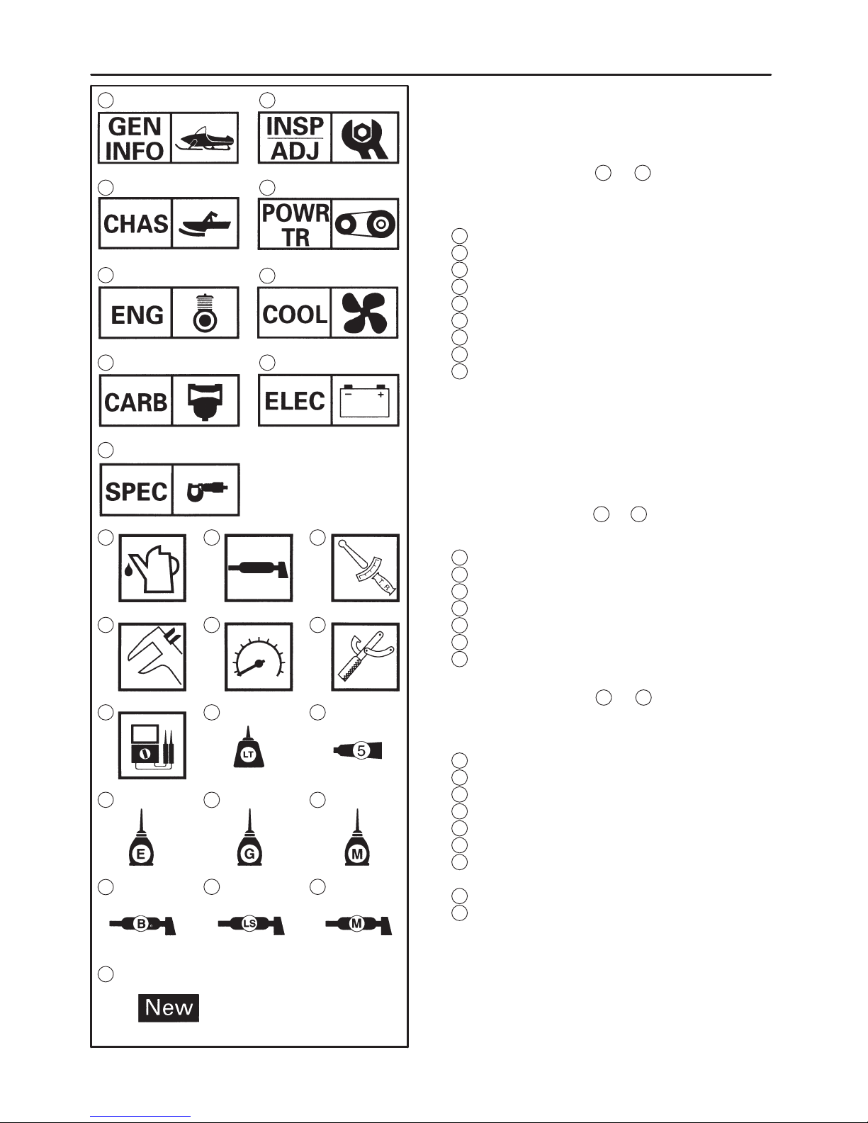
ILLUSTRATED SYMBOLS
(Refer to the illustration)
Illustrated symbols 1 to 9 are designed as
thumb tabs to indicate the chapter’s number
and content.
1
General information
2
Periodic inspection and adjustment
3
Chassis
4
Power train
5
Engine overhaul
6
Cooling system
7
Carburetion
8
Electrical
9
Specifications
Illustrated symbols 11 to 17 are used to identify the specifications which appear.
11
Filling fluid
12
Lubricant
13
Tightening
14
Wear limit, clearance
15
Engine speed
16
Special tool
17
Ω, V, A
Illustrated symbols 18 to 26 in the exploded
diagram indicate grade of lubricant and
location of lubrication point.
18
Apply locking agent (LOCTITE)
19
Apply Yamabond No.5
20
Apply engine oil
21
Apply gear oil
22
Apply molybdenum disulfide oil
23
Apply wheel bearing grease
24
Apply low-temperature lithium-soap base
grease
25
Apply molybdenum disulfide grease
26
Use new one

CONTENTS
GENERAL INFORMATION 1. . . . . . . . . . . . . .
MACHINE IDENTIFICATION 1. . . . . . . . .
FRAME SERIAL NUMBER 1. . . . . . .
ENGINE SERIAL NUMBER 1. . . . . . .
IMPORTANT INFORMATION 1. . . . . . . .
LOCTITE
1. . . . . . . . . . . . . . . . . . . . . .
POWER TRAIN 2. . . . . . . . . . . . . . . . . . . . .
DRIVE V-BELT 2. . . . . . . . . . . . . . . . . .
BRAKE PAD INSPECTION 4. . . . . . . .
SLIDE RUNNER INSPECTION 4. . . .
TUNING 5. . . . . . . . . . . . . . . . . . . . . . . . . . .
CLUTCH 5. . . . . . . . . . . . . . . . . . . . . . .
GEAR SELECTION 8. . . . . . . . . . . . . .
FRONT SUSPENSION 11. . . . . . . . . .
REAR SUSPENSION 12. . . . . . . . . . .
CHASSIS 14. . . . . . . . . . . . . . . . . . . . . . . . . . . .
SKI (500) 14. . . . . . . . . . . . . . . . . . . . . . . . .
INSPECTION 15. . . . . . . . . . . . . . . . . .
FRONT SUSPENSION 15. . . . . . . . . . . . .
INSTALLATION 16. . . . . . . . . . . . . . . .
POWER TRAIN 17. . . . . . . . . . . . . . . . . . . . . . .
SECONDARY SHEAVE 17. . . . . . . . . . . . .
ASSEMBLY 17. . . . . . . . . . . . . . . . . . . .
DRIVE CHAIN HOUSING 18. . . . . . . . . . .
WITHOUT REVERSE MODEL
(500) 18. . . . . . . . . . . . . . . . . . . . . . . . . .
INSTALLATION 19. . . . . . . . . . . . . . . .
DRIVE CHAIN HOUSING AND
JACKSHAFT INSTALLATION 20. . . .
WITH REVERSE MODEL (700) 21. . .
INSTALLATION 23. . . . . . . . . . . . . . . .
JACKSHAFT 23. . . . . . . . . . . . . . . . . . . . . .
INSPECTION 23. . . . . . . . . . . . . . . . . .
BRAKE 24. . . . . . . . . . . . . . . . . . . . . . . . . . .
BRAKE PAD REPLACEMENT 25. . . .
SLIDE RAIL SUSPENSION 27. . . . . . . . .
FRONT AXLE AND TRACK 32. . . . . . . . .
INSTALLATION 32. . . . . . . . . . . . . . . .
ENGINE 33. . . . . . . . . . . . . . . . . . . . . . . . . . . . .
ENGINE ASSEMBLY 33. . . . . . . . . . . . . . .
500 33. . . . . . . . . . . . . . . . . . . . . . . . . . .
700 34. . . . . . . . . . . . . . . . . . . . . . . . . . .
CYLINDER HEAD AND CYLINDER 35. .
INSPECTION 35. . . . . . . . . . . . . . . . . .
COOLING SYSTEM 37. . . . . . . . . . . . . . . . . . .
HEAT EXCHANGER 37. . . . . . . . . . . . . . .
CARBURETION 38. . . . . . . . . . . . . . . . . . . . . . .
CARBURETORS 38. . . . . . . . . . . . . . . . . . .
500 38. . . . . . . . . . . . . . . . . . . . . . . . . . .
700 39. . . . . . . . . . . . . . . . . . . . . . . . . . .
ASSEMBLY 41. . . . . . . . . . . . . . . . . . . .
SPECIFICATIONS 42. . . . . . . . . . . . . . . . . . . . .
GENERAL SPECIFICATIONS 42. . . . . . . .
MAINTENANCE SPECIFICATIONS 44. .
ENGINE 44. . . . . . . . . . . . . . . . . . . . . . .
POWER TRAIN 48. . . . . . . . . . . . . . . .
CHASSIS 52. . . . . . . . . . . . . . . . . . . . . .
ELECTRICAL 53. . . . . . . . . . . . . . . . . . .
CABLE ROUTING <500> 60. . . . . . . . . . .
CABLE ROUTING <700> 70. . . . . . . . . . .

–1–
500
700
MACHINE IDENTIFICATION/ IMPORTANT INFORMATION
GEN
INFO
NOTE:
1E001
GENERAL INFORMATION
MACHINE IDENTIFICATION
FRAME SERIAL NUMBER
The frame serial number
1
is located on the
right-hand side of the frame (just below the
front of the seat).
ENGINE SERIAL NUMBER
The engine serial number
1
is located on
the right-hand side of the crankcase.
Designs and specifications are subject to
change without notice.
IMPORTANT INFORMATION
LOCTITE
After installing fasteners that have LOCTITE
applied, wait 24 hours before using
the machine.
This will give the LOCTITE
time to properly
dry.
–2–
DRIVE V-BELT
INSP
ADJ
CAUTION:
NOTE:
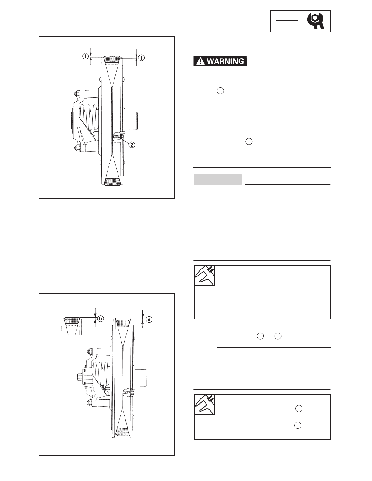
POWER TRAIN
DRIVE V-BELT
When installing the new V-belt, make sure
that it is positioned within the specified distances
1
from the edge of the secondary
sheave.
If not, the clutch engagement speed will be
changed. The machine may move unexpectedly when the engine is started.
Adjust the V-belt position by removing or
adding a spacer
2
on each adjusting bolt.
For this adjustment, consult a Yamaha dealer or another qualified mechanic.
As the V-belt wears, adjustment may be
necessary. To ensure proper clutch performance, the V-belt position should be adjusted by adding a spacer on each adjusting
bolt when the V-belt position reaches below
the edge.
For this adjustment, consult a Yamaha dealer or another qualified mechanic.
New belt width:
35.0 mm (1.38 in) (500)
34.5 mm (1.36 in) (700)
Belt wear limit width:
33.0 mm (1.30 in) (500)
32.5 mm (1.28 in) (700)
1. Measure:
S V-belt position
a
or
b
Install the new V-belt onto the secondary
sheave only. Do not force the V-belt between
the sheaves; the sliding and fixed sheave
must touch each other.
Standard V-belt height
(Below sheave surface)
a
(500):
0 X 2 mm (0 X 0.08 in)
Standard V-belt height
b
(700):
–0.5 X 1.5 mm (– 0.02 X 0.06 in)
S Out of specification ! Adjust.

–3–
DRIVE V-BELT
INSP
ADJ
2. Adjust the position of the V-belt by removing or adding a spacer
1
on each
adjusting bolt
2
.
V-belt height adjustment
To move V-belt up: Add spacer
To move V-belt down: Reduce spacer
3. Tighten:
S Adjusting bolt
Adjusting bolt:
10 Nm (1.0 mSkg, 7.2 ftSlb)
4. Inspect:
S Drive V-belt
Cracks/ damage /wear ! Replace.
Oil or grease on the V-belt ! Check the
primary and secondary sheaves.
5. Inspect:
S Primary sheave
S Secondary sheave
Oil or grease on the primary and secondary sheaves ! Use a rag soaked in
lacquer thinner or solvent to remove
the oil or grease. Check the primary and
secondary sheaves.
6. Measure:
S Drive V-belt length
a
Out of specification ! Replace.
Drive V-belt length:
500
1,119 X 1,129 mm
(44.063 X 44.437 in)
700
1,129 X 1,137 mm
(44.4 X 44.7 in)
–4–
BRAKE PAD INSPECTION/ SLID RUNNER INSPECTION
INSP
ADJ
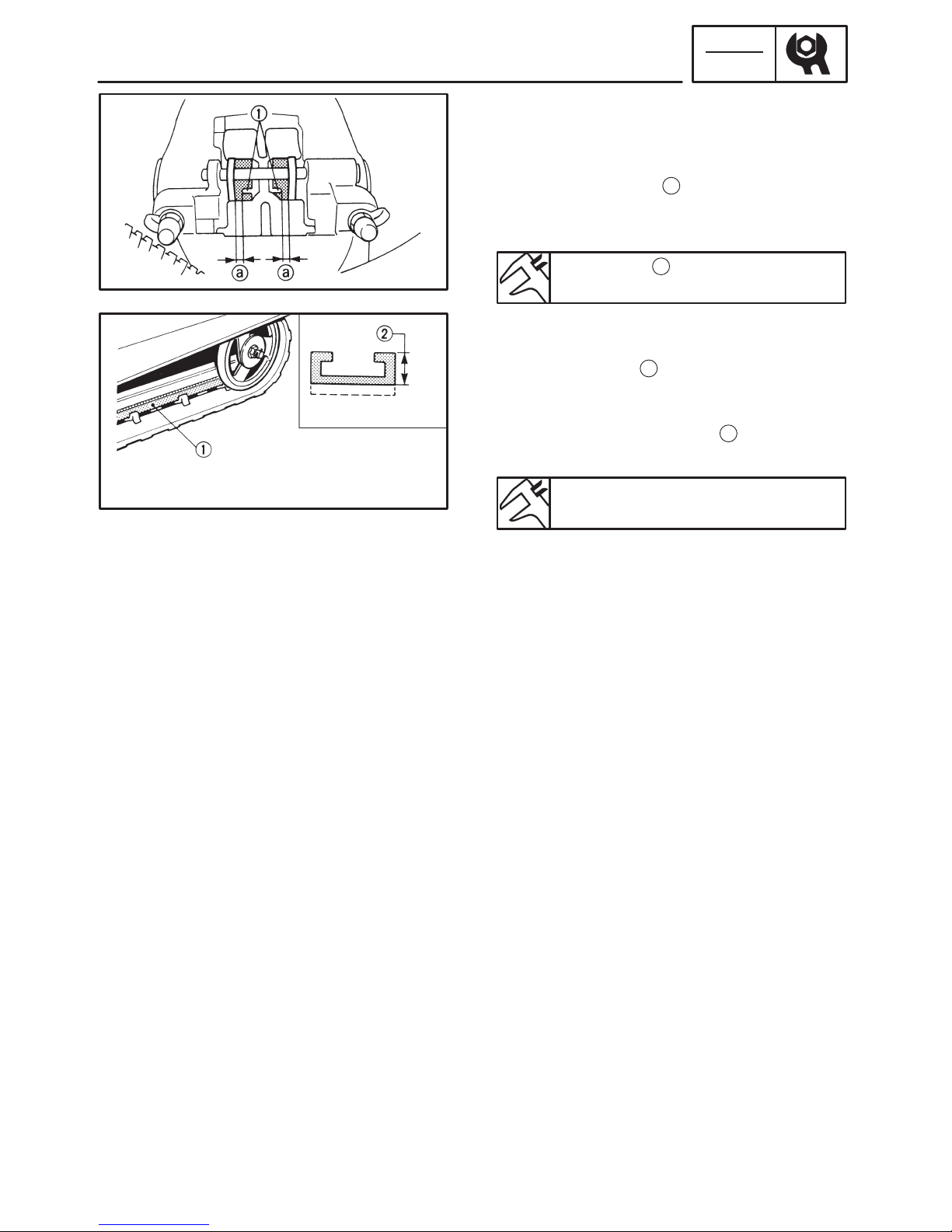
BRAKE PAD INSPECTION
1. Apply the brake lever.
2. Inspect:
S Brake pad
Wear indicator
1
nearly contacts the
brake disc ! Replace the brake pads as
a set.
Wear limit
a
:
4.7 mm (0.185 in)
SLIDE RUNNER INSPECTION
1. Inspect:
S Slide runner
1
Cracks/ damage /wear ! Replace.
2. Measure:
S Slide runner thickness
2
Out of specification ! Replace.
Slide runner wear limit:
10 mm (0.39 in)
–5–
CLUTCH
INSP
ADJ
A
B
C
D
E
F
G
H
I
J
K
L
M
N
O
P
Q
R
S
T
U
V
W
X
Z
Y
a
b
d
TUNING
CLUTCH
High altitude
W
White S Silver L Blue
P Pink R Red O Orange
Y Yellow G Green
Specifications Model: VX500SXB
Elevation X 3,500 ft 3,000 X 5,000 ft
4,500 X 7,000 ft
6,500 X 10,000 ft
Idle speed Approx.
1,600 r/ min
z z z
Clutch
engagement
Approx.
4,000 r/ min
4,100 r/ min 4,200 r/ min
z
Shift speed Approx.
7,800 r/ min
z z z
Main jet #151.3 (STD)
Pilot (slow) jet #45 (STD) See MAINTENANCE SPECIFICATIONS (High altitude settings)
Idle mixture
screw
1-3/ 4 (STD)
Gearing
22/ 39 (70L)
21/ 39 (68L)
20/ 39 (68L) 19/ 39 (68L)
Primary spring
Color
Length
Preload rate
Wire diameter
Outside
diameter
W-P-W
78.7 mm
30 kg – 2.25
kg/ mm
ø5.5 mm
ø60 mm
z
z
z
z
z
Y-P-Y
77.4 mm
30 kg – 2.5
kg/ mm
ø5.8 mm
z
O-P-O
74.6 mm
30 kg – 3.25
kg/ mm
ø6.0 mm
z
Weight (1D)
Weight rivet
Weight
bushing
8CR
Steel 13.9 (OUT)
Aluminum 10.3
(IN)
Duralon
z
Aluminum 10.3
(OUT)
None (IN)
z
z
None (OUT)
None (IN)
z
z
None (OUT)
None (IN)
z
Roller outer dia.
Roller bushing
ø15.0 mm
Duralon
z
z
z
z
z
z
Pri. clutch shim None z z z
Secondary
spring
Color
Length
Preload rate
Wire diameter
Outside
diameter
R
75 mm
90_ (3-6)
729 kgmm/ rad
ø5.3 mm
ø69.5 mm
z
z
z
z
z
z
z
z
z
z
z
z
z
z
z
Sec. torque cam 43_ z z z
Sec. clutch shim 1.0 mm z z z

–6–
CLUTCH
INSP
ADJ
A
B
C
D
E
F
G
H
I
J
K
L
M
N
O
P
Q
R
S
T
U
V
W
X
Z
Y
a
b
See MAINTENANCE SPECIFICATIONS
(High altitude settings)
d
W white S Silver L Blue
P Pink R Red O Orange
Y Yellow G Green
Specifications Model: VX700ER
Elevation X 3,500 ft 3,000 X 5,000 ft 4,500 X 7,000 ft 6,500 X 10,000 ft
Idle speed Approx. 1,600
r/min
z z z
Clutch
engagement
Approx. 4,000
r/min
z z z
Shift speed Approx. 8,300
r/min
z z z
Main jet #1: #145
#2, 3: #143.8 (STD)
Pilot (slow) jet #45 (STD)
Idle mixture
screw
1-1/ 2 (STD)
Gearing 22/ 39 (70L) z z 22/ 40 (70L)
Primary spring
Color
Length
Preload rate
Wire diameter
Outside
diameter
W-S-W
81.0 mm
35 kg – 2.25
kg/ mm
ø5.5 mm
ø48.0 mm
G-P-G
76.3 mm
30 kg – 2.75
kg/ mm
ø5.8 mm
ø48.0 mm
P
75.4 mm
30 kg – 3.0
kg/ mm
ø6.0 mm
ø60.0 mm
z
z
z
z
z
Weight (1D)
Weight rivet
Weight bushing
8CH-00
Steel 10.3 (OUT)
Steel 13.9 (IN)
Duralon
z
Steel 10.3 (OUT)
Steel 13.9 (IN)
z
z
Aluminum 10.3
(OUT)
Steel 13.9 (IN)
z
z
None (OUT)
Steel 13.3 (IN)
z
Roller outer dia.
Roller bushing
ø14.5 mm
Duralon
z
z
z
z
z
z
Pri. clutch shim None z z z
Secondary
spring
Color
Length
Preload rate
Wire diameter
G
75 mm
60_ (3-3)
848 kgmm/ rad
ø5.5 mm
z
z
z
z
R
z
60_ (3-3)
729 kgmm/ rad
ø5.3 mm
z
z
z
z
Outside
diameter
ø69.5 mm z z z
Sec. torque cam 45_ z z z
Sec. clutch shim 1.0 mm z z z

–7–
CLUTCH
INSP
ADJ
2E331
The clutch may require tuning depending
upon the area of operation and desired handling characteristics. The clutch can be
tuned by changing engagement and shifting
speed. Clutch engagement speed is defined
as the engine speed where the machine first
begins to move from a complete stop.
Shifting speed is when the machine has
been started at full-throttle from a dead stop
and has travelled 200 X 300 m (650 X 1,000
ft).
Normally, when a machine reaches shifting
speed, the vehicle speed increases but the
engine speed remains nearly constant. Under unfavorable conditions (wet snow, icy
snow, hills, or rough terrain), however, engine speed may decrease after the shifting
speed has been reached.
A
Engine speed
B
Good condition
C
Bad condition
D
Clutch shifting speed
E
Clutch engagement speed
F
Starting position
G
200 X 300 m (650 X 1,000 ft)
H
Distance travelled
–8–
GEAR SELECTION
INSP
ADJ
NOTE:
A B C D
E
F
G
Driven gear
Drive gear
B
A
GEAR SELECTION
The reduction ratio of the driven gear to the
drive gear must be set according to the snow
conditions. If there are many rough surfaces
or unfavorable snow conditions, the
drive/ driven gear ratio should be increased.
If the surfaces are fairly smooth or better
snow conditions exist, decrease the ratio.
Gear ratio chart
The following drive and driven gears and
chains are available as options. The figures
in the upper lines represent the drive/ driven
gear ratios, while the number on the following line, followed by an “L”, designates the
number of chain links.
Do not set the gearing to any of the indicated
(x) settings.
1
Chain and sprocket parts number:
Parts name Teeth & Links Parts No. Standard
18T 89J-17682-80
19T 89J-17682-91
20T 89J-17682-00
Drive sprocket
21T 89J-17682-10
22T 89J-17682-20 VX500, VX700
23T 89J-17682-30
39T 89J-47587-90 VX500
Driven sprocket
40T 89J-47587-00
39T (REVERSE) 8CW-47587-90 VX700
Chain (links)
68LINKS 94860-02068
70LINKS 94860-02070 VX500, VX700
2
Gear ratio
18T
19T
20T
21T
22T
23T
39T
2.17
68L
2.05
68L
1.95
68L
1.86
68L
1.77
70L
1.70
70L
40T*
2.22
68L
2.10
68L
2.00
68L
1.90
70L
1.82
70L
1.74
70L
* Not for reverse models

–9–
GEAR SELECTION
INSP
ADJ
A
B
C
D
E F
G
A
Sheave
Seat
B
A B C
3
Secondary spring
Parts No.
Spring rate
NSmm/ rad
(kgmm/ rad)
No. of
coils
Color
Wire
gauge
(mm)
Free
length
(mm)
Standard
90508-500B1 6003 (613) 5.2 BROWN 5.0 75
90508-536A9 7147 (729) 5.5 RED 5.3 75 VX500
90508-556A2 8314 (848) 5.5 GREEN 5.5 75 VX700
90508-556A7 9460 (965) 4.8 SILVER 5.5 75
4
Secondary spring twist angle
0 3 6 9
1 10_ 40_ 70_ 100_
2 20_ 50_ 80_ 110_
3 30_ 60_ 90_ 120_
5
Torque cam (secondary spring seat)
Parts No. Cam angle Standard
8BV-17604-10 41_
8BV-17604-30 43_ VX500
8BV-17604-50 45_ VX700
8BV-17604-70 47_
8BV-17604-90 39_

–10–
GEAR SELECTION
INSP
ADJ
A
E HB
C
D
F
G
I
6
Primary spring
Parts No.
Spring rate
N/mm
(kg/ mm)
Preload
(kg)
Color
Wire
gauge
(mm)
Outside
diameter
(mm)
No. of
coils
Free
length
(mm)
Standard
90501-481J1 9.8 (1.0) 196.1 (20) S-B-S 4.8 60 5.16 85.4
90501-487G8 14.7 (1.5) 147 (15) G 4.8 60 4.19 75.4
90501-507G2 14.7 (1.5) 196.1 (20) G-B-G 5.0 60 4.61 78.7
90501-524G5 14.7 (1.5) 245 (25) G-Y-G 5.2 60 5.08 82.1
90501-507G7 17.1 (1.75) 147 (15) R-G-R 5.0 60 4.24 74.0
90501-524G4 17.1 (1.75) 245 (25) R-Y-R 5.2 60 4.64 79.7
90501-526J9 17.2 (1.75) 294 (30) R-P-R 5.2 48 4.77 82.5
90501-527G1 17.2 (1.75) 196.1 (20) R-B-R 5.2 60 4.65 76.8
90501-525J8 19.6 (2.0) 294 (30) B-P-B 5.2 48 4.43 80.4
90501-526G4 19.6 (2.0) 147 (15) B-G-B 5.2 60 4.32 72.9
90501-553G0 19.6 (2.0) 245 (25) B-Y-B 5.5 60 5.10 78.0
90501-556G6 19.6 (2.0) 196.1 (20) B 5.5 60 4.95 75.4
90501-550J8 22 (2.25) 294 (30) W-P-W 5.5 60 4.62 78.7 VX500
90501-553G6 22 (2.25) 245 (25) W-Y-W 5.5 60 4.61 76.5
90501-555J9 22 (2.25) 343 (35) W-S-W 5.5 48 4.66 81.0 VX700
90501-556G5 22 (2.25) 196.1 (20) W-B-W 5.5 60 4.62 74.3
90501-557G6 22 (2.25) 147 (15) W-G-W 5.5 60 4.62 72.1
90501-556G7 24.5 (2.5) 196.1 (20) Y-G-Y 5.5 60 4.36 73.4
90501-581J7 24.5 (2.5) 245 (25) Y 5.8 60 4.96 75.4
90501-582J1 24.5 (2.5) 294 (30) Y-P-Y 5.8 60 4.96 77.4
90501-586J0 24.5 (2.5) 343 (35) Y-S-Y 5.8 48 4.91 79.4
90501-605G7 26.8 (2.74) 235 (24) G-Y-G 6.0 60 5.00 74.1
90501-585J3 27 (2.75) 294 (30) G-P-G 5.8 48 4.64 76.3
90501-607G0 27 (2.75) 196.1 (20) G-B-G 6.0 60 5.12 72.7
90501-607G4 27 (2.75) 147 (15) Gr-g-Gr 6.0 60 5.12 70.9
90501-602J0 29.4 (3.0) 294 (30) P 6.0 60 4.74 75.4
90501-604G0 29.4 (3.0) 235 (24) P-Y-P 6.0 60 4.80 73.3
90501-606G9 29.4 (3.0) 196.1 (20) P-B-P 6.0 60 4.86 72.1
90501-607G3 29.4 (3.0) 147 (15) P-G-P 6.0 60 4.86 70.4
90501-605J5 31.9 (3.25) 294 (30) Or-P-Or 6.0 48 4.53 74.6
Color
B– Blue G– Gold Gr– Green Or– Orange P– Pink R– Red
S– Silver W– White Y– Yellow
–11–
FRONT SUSPENSION
INSP
ADJ
CAUTION:
a
CAUTION:
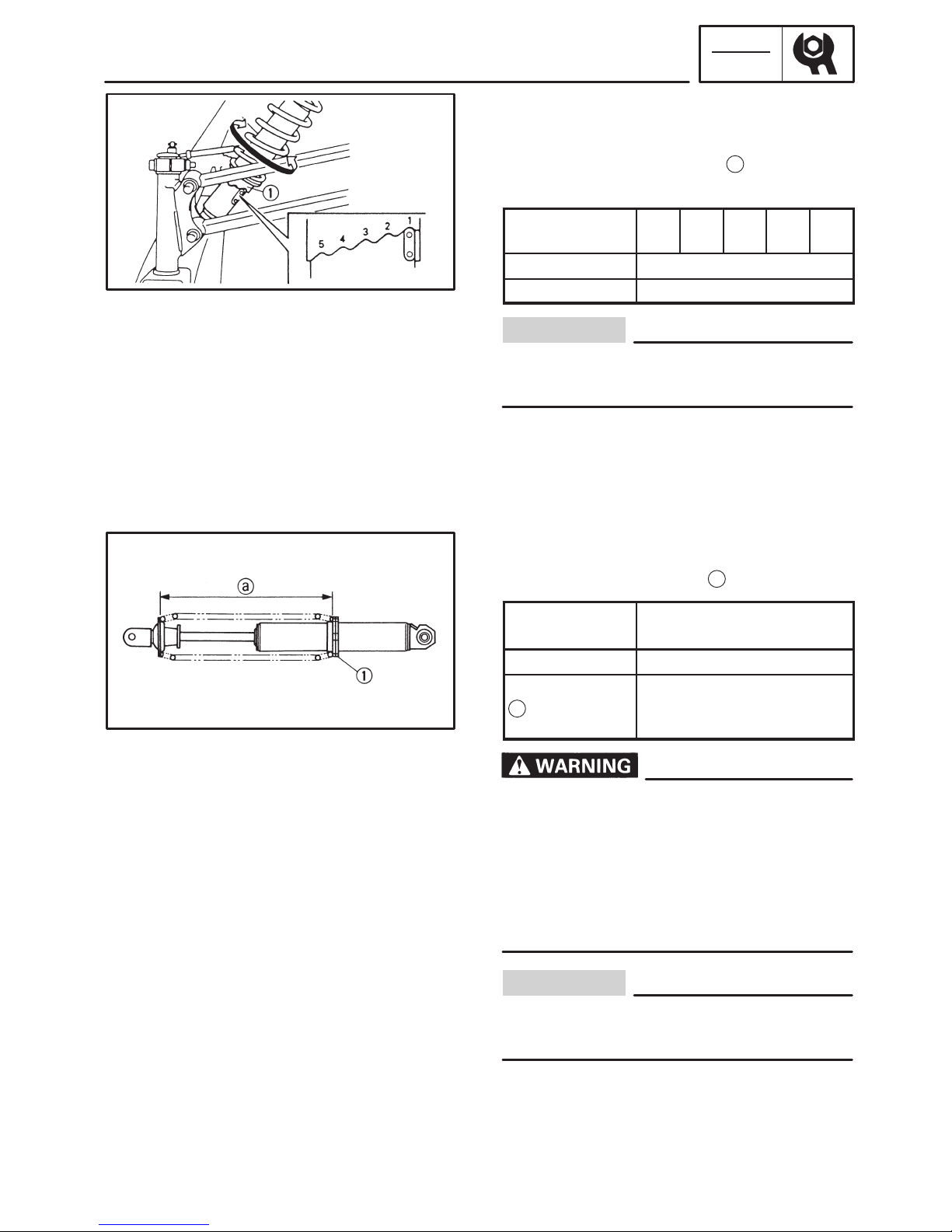
FRONT SUSPENSION
Spring preload (700)
1. Adjust:
S Turn the adjusting ring
1
to the proper
position.
Spring adjuster
position
1 2 3 4 5
Preload Softer z! Harder
Standard 1
Be sure that the left and right spring preload
is the same.
Spring preload (500)
1. Adjust:
S Turn the spring seat
1
in or out.
Spring seat
distance
Standard
Shorter z! Longer
Preload Harder z! Softer
Length
Max. Min.
213 mm 223 mm 233 mm
(8.39 in) (8.78 in) (9.17 in)
This shock absorber contains highly pressurized nitrogen gas.
Do not tamper with or attempt to open the
shock absorber assembly.
Do not subject the shock absorber assembly
to an open flame or high temperature, as
this could cause it to explode.
Be sure that the left and right spring preload
is the same.
–12–
A
B
REAR SUSPENSION
INSP
ADJ
CAUTION:
NOTE:
A
B
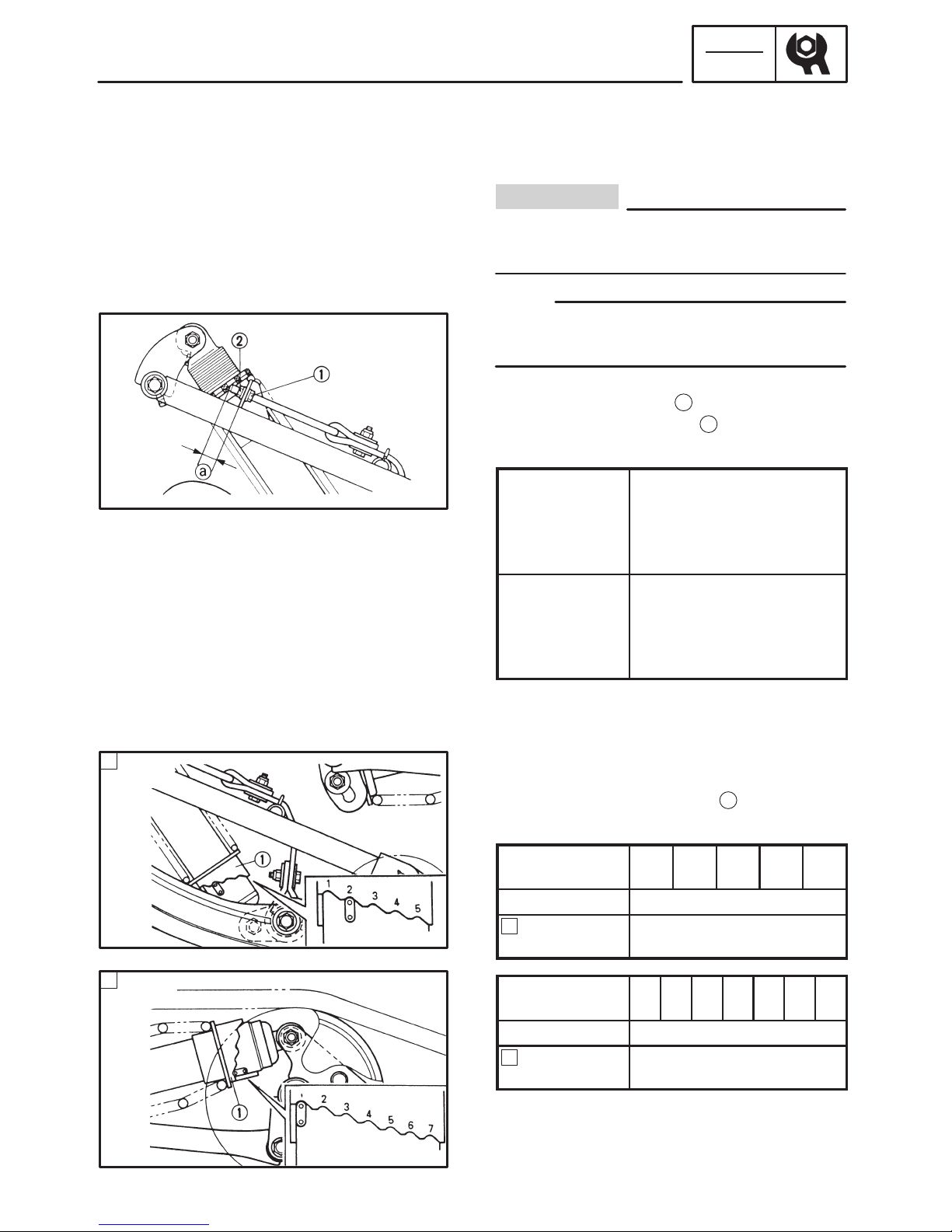
REAR SUSPENSION
Stopper band
1. Adjust:
S Stopper band tension
Be sure that the left and right length is the
same.
This adjustment affects the handling characteristics of the machine.
Adjustment steps:
S Loosen the locknut
1
.
S Turn the adjusting nut
2
in or out to
adjust the stopper band tension.
Adjuster
Thread
length
Longer z! Shorter
maximum minimum
STD
500 15 mm (0.59 in)
700 10 mm (0.39 in)
Effects More weight Less
on skis. Less weight on
weight skis. More
transfer weight
transfer
S Tighten the locknut.
Spring preload (700)
1. Adjust:
S Turn the adjusting ring
1
to the proper
position.
Spring adjuster
position
1 2 3 4 5
Preload Softer z! Harder
Standard
(front)
1
Spring adjuster
position
1 2 3 4 5 6 7
Preload Softer z! Harder
Standard
(rear)
2

–13–
A
B
REAR SUSPENSION
INSP
ADJ
A
a
B
b
Spring preload (500)
1. Adjust:
S Turn the spring seat
1
in or out.
Spring seat
distance
Standard
Shorter z! Longer
Preload Harder z! Softer
Length
(front)
Max. Min.
172 mm 182 mm 192 mm
(6.77 in) (7.17 in) (7.56 in)
Length
(rear)
Max. Min.
302 mm 312 mm 322 mm
(11.89 in) (12.28 in) (12.68 in)
This shock absorber contains highly pressurized nitrogen gas.
Do not tamper with or attempt to open the
shock absorber assembly.
Do not subject the shock absorber assembly
to an open flame or high heat, which could
cause it to explode.

–14–
SKI
CHAS
Order Job name/ Part name Q’ty Remarks
1
2
3
4
5
6
7
8
9
Ski removal
Cotter pin
Ski column lower bracket
Ski stopper
Collar
Washers
Ski
Ski runner
Washers
Ski handle
1
1
1
1
6
1
1
6
1
Remove the parts in the order below.
For installation, reverse the removal
procedure.
10 Nm (1.0 mSkg, 7.2 ftSlb)
A:
21 Nm (2.1 mSkg, 15 ftSlb)
B:
48 Nm (4.8 mSkg, 35 ftSlb)
C:
: ESSO beacon 325
grease or Aeroshell
grease #7A
CHASSIS
SKI (500)

–15–
SKI/FRONT SUSPENSION
CHAS
INSPECTION
1. Inspect:
S Ski
1
S Ski runner
2
S Ski column lower bracket
3
S Ski handle
4
S Ski stopper
5
Wear/ cracks/ damage ! Replace.
S Mounting bolt
6
S Collar
7
Wear/ damage ! Replace.
FRONT SUSPENSION
This shock absorber contains highly compressed nitrogen gas. Before handling the
shock absorber read and make sure that you
understand the following information. The
manufacturer cannot be held responsible
for property damage or personal injury that
may result from improper handling.
D Do not tamper or attempt to open the gas
chamber.
D Do not subject the shock absorber to an
open flame or any other source of high
heat. This may cause the unit to explode
due to excessive gas pressure.
D Do not deform or damage the gas cham-
ber in any way. Gas chamber damage will
result in poor damping performance.
–16–
FRONT SUSPENSION
CHAS
C
a
H
I
F B
D
H
I
C
a
H
I
F B
E
H
I
NOTE:
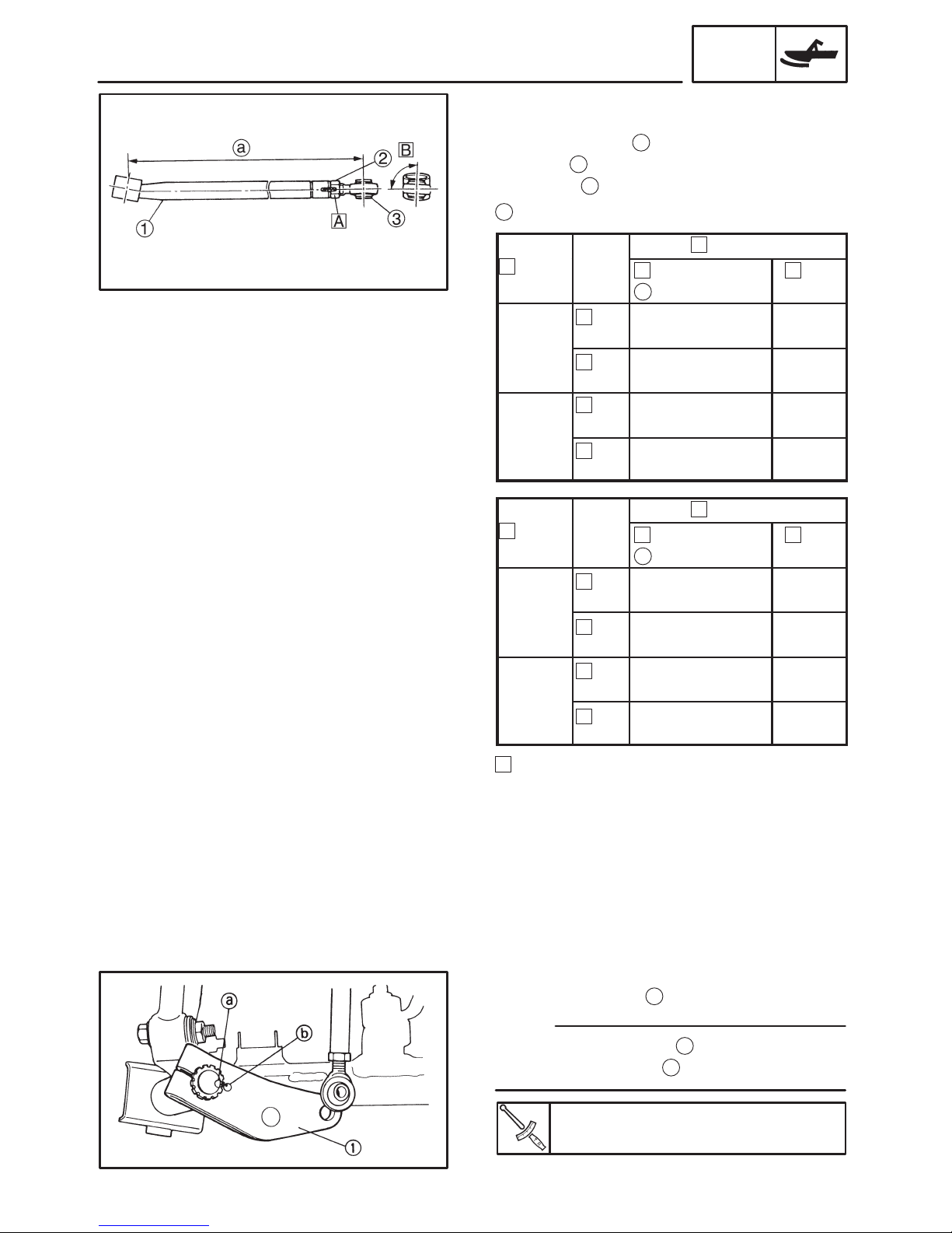
INSTALLATION
1. Install:
S Control rod
1
S Nut
2
S Joint
3
a
Set length
Left hand
Model
Set length
(mm)
Set
angle (_)
VX500
Upper
460.2 ± 0.5 mm
(18.11 ± 0.0197 in)
94 ± 1
Lower
458.7 ± 0.5 mm
(18.059 ± 0.0197 in)
94 ± 1
VX700
Upper
475.5 ± 0.5 mm
(18.012 ± 0.0197 in)
93 ± 1
Lower
472.6 ± 0.5 mm
(18.606 ± 0.0197 in)
93 ± 1
Right hand
Model
Set length
(mm)
Set
angle (_)
VX500
Upper
460.2 ± 0.5 mm
(18.11 ± 0.0197 in)
86 ± 1
Lower
458.7 ± 0.5 mm
(18.059 ± 0.0197 in)
86 ± 1
VX700
Upper
475.5 ± 0.5 mm
(18.012 ± 0.0197 in)
87 ± 1
Lower
472.6 ± 0.5 mm
(18.606 ± 0.0197 in)
87 ± 1
A
14 mm = 62 X 84 Nm (6.2 X 8.4 mSkg,
14 mm = 45 X 60 ftSlb)
2. Install:
S Steering arm
1
Align the punch mark a on the ski column
with the punch mark
b
on the steering arm.
Nut (steering arm):
54 Nm (5.4 mSkg, 38 ftSlb)
–17–
SECONDARY SHEAVE
POWR
TR
NOTE:
NOTE:
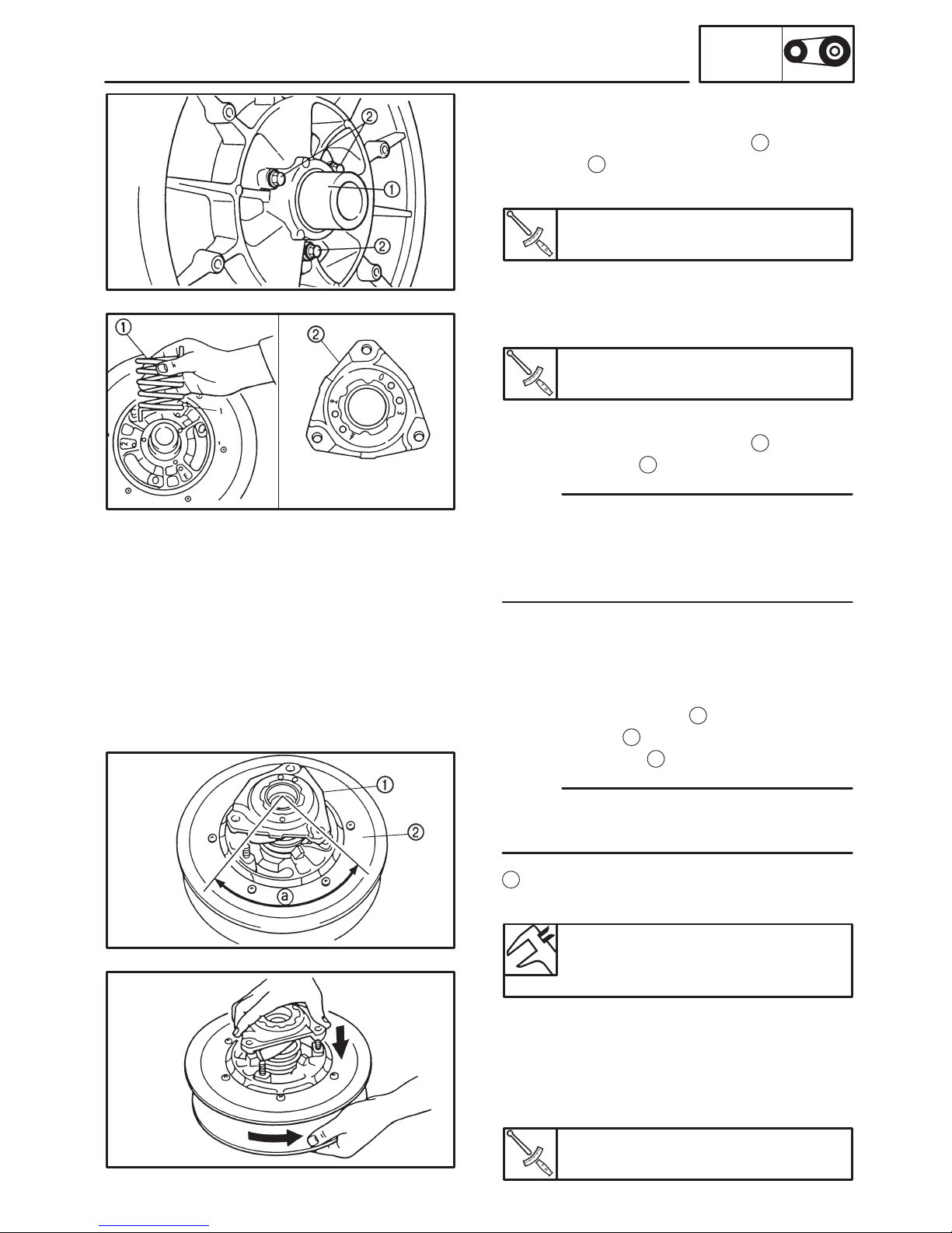
ASSEMBLY
1. Install:
S Secondary sheave spring
1
S Bolts
2
(along with the shims)
Bolt:
10 Nm (1.0 mSkg, 7.2 ftSlb)
2. Install:
S Stopper
S Sliding sheave
Screw (stopper):
6.5 Nm (0.65 mSkg, 4.6 ftSlb)
3. Install:
S Secondary sheave spring
1
S Spring seat
2
Hook the end of the secondary sheave
spring into the spring holes in the fixed
sheave. Hook the other end of the spring into
the holes in the spring seat.
Standard spring position:
500 3-6
700 3-3
Installation steps:
D Hold the spring seat
1
and turn the slid-
ing sheave
2
counterclockwise to the
specified angle
a
.
The holes in the spring seat should align
with the bolts on the fixed sheave.
a
= (sheave side hole number + spring seat
hole number) 10
Standard angle:
500 90_
700 60_
D Push down on the spring seat until the
bolts come through the holes.
D While pushing down on the spring seat,
install the nuts and tighten them to the
specified torque.
Nut (spring seat):
23 Nm (2.3 mSkg, 17 ftSlb)
–18–
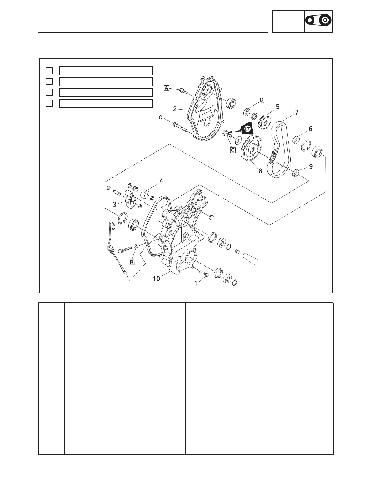
Order Job name/ Part name Q’ty Remarks
1
2
3
4
5
6
7
8
9
10
Drive chain housing removal
Brake caliper
Parking brake
Tension adjuster
Bolt
Drive chain housing cover
Chain tensioner
Roller
Drive sprocket
Collar
Drive chain
Driven sprocket
Collar
Drive chain housing
1
1
1
1
1
1
1
1
1
1
Remove the parts in the order below.
Refer to “BRAKE”.
Loosen. Refer to “SLIDE RAIL
SUSPENSION”.
Oil drain.
For installation, reverse the removal
procedure.
10 Nm (1.0 mSkg, 7.2 ftSlb)
A:
24 Nm (2.4 mSkg, 17 ftSlb)
B:
48 Nm (4.8 mSkg, 35 ftSlb)
C:
60 Nm (6.0 mSkg, 43 ftSlb)
D:
DRIVE CHAIN HOUSING
POWR
TR
DRIVE CHAIN HOUSING
WITHOUT REVERSE MODEL (500)

–19–
DRIVE CHAIN HOUSING
POWR
TR
INSTALLATION
During installation, pay attention to the following point:
A
Make sure that the bearing seals face towards
the drive chain, as shown.
B
Properly install the rubber seal onto the drive
chain housing, making sure that these are no
gaps.
C
Be sure to install the spacers in their original
positions of the brake disc and jackshaft will
stick.
D
0.1 X 0.5 mm (0.004 X 0.020 in)
: ESSO beacon 325 grease or Aero-
shell grease #7A
–20–
DRIVE CHAIN HOUSING
POWR
TR
DRIVE CHAIN HOUSING AND JACKSHAFT
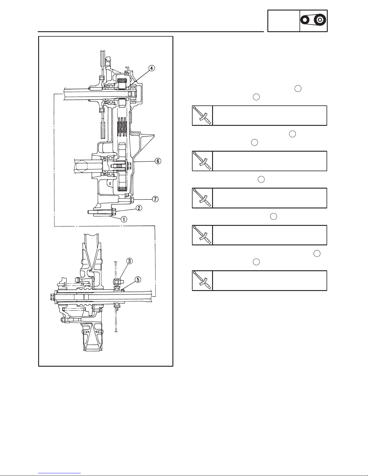
INSTALLATION
1. Install:
S Drive chain housing
S Jackshaft
Installation steps:
D Install the drive chain housing
1
.
D Tighten the bolts
2
.
Bolt (drive chain housing):
48 Nm (4.8 mSkg, 35 ftSlb)
D Temporarily tighten the nuts
3
.
D Tighten the nuts
3
.
Nut (jackshaft):
60 Nm (6.0 mSkg, 43 ftSlb)
D Retighten the nuts
3
.
Nut (bearing holder):
23 Nm (2.3 mSkg, 17 ftSlb)
D Tighten the set screws
5
.
Set screw (bearing):
8.5 Nm (0.85 mSkg, 6.1 ftSlb)
D Install the drive chain housing cover
6
.
D Tighten the bolts
7
.
Bolt (drive chain housing cover):
24 Nm (2.4 mSkg, 17 ftSlb)
–21–
Order Job name/ Part name Q’ty Remarks
1
2
3
4
5
6
7
8
9
Drive chain housing removal
Battery
Battery bracket
Brake caliper
Parking brake
Tension adjuster
Joints
Shift rod
Shift lever assembly
Lever
Joints
Lever rod
Bolt
Drive chain housing cover
Washer
2
1
1
1
2
1
1
1
1
Remove the parts in the order below.
Refer to “BRAKE”.
Loosen. Refer to “SLIDE RAIL
SUSPENSION”.
Oil drain.
10 Nm (1.0 mSkg, 7.2 ftSlb)
A:
24 Nm (2.4 mSkg, 17 ftSlb)
B:
48 Nm (4.8 mSkg, 35 ftSlb)
C:
60 Nm (6.0 mSkg, 43 ftSlb)
D:
DRIVE CHAIN HOUSING
POWR
TR
WITH REVERSE MODEL (700)

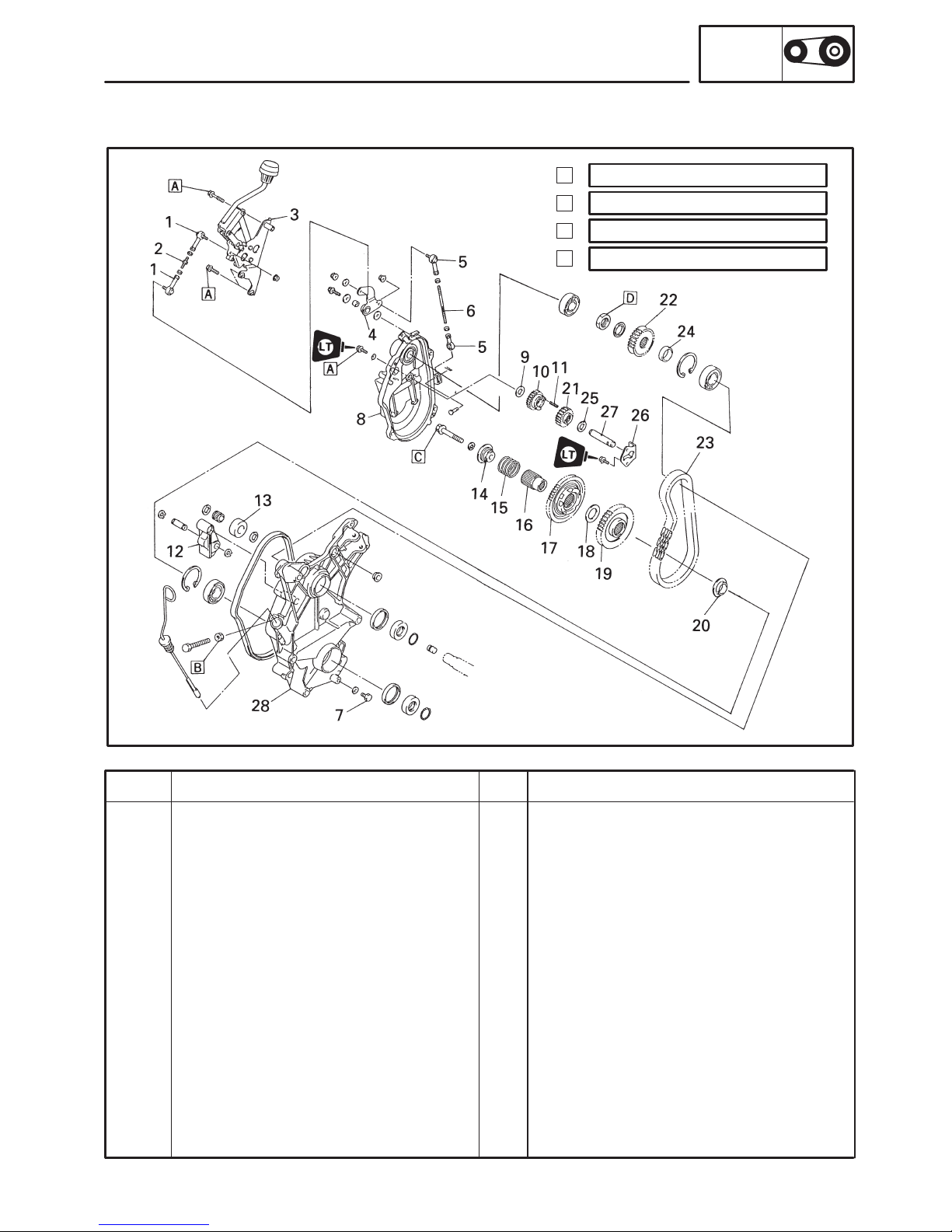
–22–
Order
Job name/ Part name Q’ty Remarks
10
11
12
13
14
15
16
17
18
19
20
21
22
23
24
25
26
27
28
Reverse drive gear
Spring
Chain tensioner
Roller
Collar
Spring
Journal
Reverse driven gear
Washer
Forward driven sprocket
Collar
Counter gear
Drive sprocket
Drive chain
Collar
Washer
Plate
Shaft
Drive chain housing
1
1
1
1
1
1
1
1
1
1
1
1
1
1
1
1
1
1
1
For installation, reverse the removal
procedure.
DRIVE CHAIN HOUSING
POWR
TR
 Loading...