

Page 1

YAMAHA
SY85 Music Synthesizer
Owner’s Manual 2
- Feature Reference -
Page 2

GENERAL EDITING PROCEDURE
PERFORMANCE EDIT MODE
VOICE EDIT MODE
DRUM VOICE EDIT MODE
SONG EDIT MODE
PATTERN EDIT MODE
UTILITY MODE
WAVE EDIT MODE
APPENDIX
Page 3

CONTENTS
GENERAL EDITING PROCEDURE
■ Mode Selection.............................................8
■ Selecting Specific Edit Functions...............8
■ Selecting & Editing Parameters................10
■ Controller Assignment Display..................11
Performance Edit Mode
■ Edit
1: Layer
1: Voice Number .................................14
2: Vo l u m e .............................................15
3: Pa n ...................................................16
4: Tune .................................................17
5: No t e Li m i t ........................................18
6: Ve l o c i t y Li m i t...................................2 0
7: CS Enable .......................................22
Layer Data Copy.................................23
2: Performance Total Level .....................24
3: Performance Name ..............................25
4: Layer Voice Edit
1: Oscillator..........................................26
2: Amplitude EG..................................26
3: Filter .................................................26
4: Pi t c h EG ..........................................26
5: LF O ..................................................2 6
6: Controller .........................................26
7: Voice Total Level ...........................26
8: Voice Name.....................................26
■ Quick Edit
1: Amplitude EG Offset............................27
2: LFO & Filter Offset ..............................29
3: Controller Conditions ...........................31
4: Other Conditions ..................................33
5: Effect Type............................................35
6: Effect Parameter ..................................36
■ Effect Edit
1: Mode, Type ...........................................37
2: Send Select & Level............................38
3: Layer Dry Output Select .....................40
4: Output Level .........................................41
5: Wet : Dry Balance ...............................42
6: Send & Effect 2 Mix Level .................43
7: Effect 1 Parameters.............................44
8: Effect 2 Parameters.............................44
9: Control Parameters ..............................45
10: Control LFO ........................................47
Effect Data Copy .......................................48
Effect Signal Flow Display.......................49
■ Job
1: Layer Controller Sync..........................50
2: Layer Exchange....................................51
3: Performance Edit Recall .....................52
4: Performance Initialize ..........................53
■ Performance Compare ...............................54
■ Performance Store .....................................55
Voice Edit Mode
■ Edit
1: Oscillator................................................58
2: Amplitude EG
1: AEG Level & Rate .........................60
2: Level Scaling ..................................62
3: Sensitivity ........................................63
AEG Data Copy...................................64
3: Filter
1: Type, Cutoff Frequency.................65
2: Cu t o f f Sc a l i n g .................................6 9
3: FEG Level & Rate ..........................70
4: Filter Sensitivity ..............................72
Filter Data Copy..................................73
4: Pitch EG
1: Level & Rate...................................74
2: Range, Sensitivity...........................76
Pitch EG Data Copy ...........................77
5: LFO
1: LF O ..................................................7 8
2
Page 4

2: LFO Speed Sensitivity ...................80
LFO Data Copy ...................................81
6: Controller
1: Pitch Bend Range ..........................82
2: Modulation Wheel Depth ...............83
3: Foot Controller Depth ....................85
4: After Touch Depth..........................87
5: CS3 Parameter Edit.......................89
6: CS4 Parameter Edit.......................91
Controller Data Copy..........................93
7: Voice Total Level ...........................94
8: Voice Name.....................................95
Drum Voice Edit Mode
■ Edit
1: Key Parameters 1 ............................. 120
2: Key Parameters 2 ............................. 122
3: Total Level ......................................... 123
4: Drum Voice Name............................. 124
Drum Key Data Copy ............................ 125
■ Quick Edit
1: Effect Type......................................... 126
2: Effect Send Level.............................. 127
■ Quick Edit
1: Wave ......................................................96
2: Amplitude EG........................................98
3: Filter .................................................... 100
4: LF O ..................................................... 1 0 2
5: Effect Type......................................... 103
6: Effect Parameter ............................... 104
■ Effect Edit
1: Mode, Type ........................................ 105
2: Send, Mix, Wet : Dry........................ 106
3: Output Level ...................................... 108
4: Effect 1 Parameters.......................... 109
5: Effect 2 Parameters.......................... 109
6: Control Parameters ........................... 110
7: Ef f e c t LF O .......................................... 11 2
Effect Data Copy .................................... 113
Effect Signal Flow Display.................... 114
■ Job
1: Voice Edit Recall............................... 115
2: Voice Initialize ................................... 116
■ Effect Edit
1: Mode, Type ........................................ 128
2: Key Send Select & Level................. 129
3: Key Dry Output Select ..................... 131
4: Output Level ...................................... 132
5: Wet : Dry Balance ............................ 133
6: Send & Effect 2 Mix Level .............. 134
7: Effect 1 Parameter2.......................... 135
8: Effect 2 Parameter2.......................... 135
9: Control Parameters ........................... 136
10: Control LFO ..................................... 138
Effect Data Copy .................................... 139
Effect Signal Flow Display.................... 140
■ Job
1: Key Data Initialize............................. 141
2: Key Data Exchange .......................... 142
3: Drum Voice Edit Recall.................... 143
4: Drum Voice Initialize......................... 144
■ Drum Voice Compare ............................. 145
■ Voice Compare ........................................ 117
■ Voice Store............................................... 118
■ Drum Voice Store .................................... 146
3
Page 5

Song Edit Mode
■ Multi Edit
1: Vo i c e Se l e c t ....................................... 14 8
2: Vo l u m e ................................................ 149
3: Pa n ...................................................... 15 0
4: Effect Send Level.............................. 151
5: No t e Sh i f t ........................................... 1 5 2
6: Tune .................................................... 153
7: Effect Type, Out Balance................. 154
8: Song Name ........................................ 155
9: Song Initialize .................................... 156
■ Track Edit ................................................. 157
15: Ve l o c i t y Mo d i f y ................................ 1 9 8
16: Ga t e Ti m e Mo d i f y ........................... 19 9
17: Crescendo ........................................ 200
Pattern Edit Mode
■ Job
1: Copy Pattern...................................... 202
2: Clear Pattern ...................................... 203
3: Instrument Change............................ 204
4: Ve l o c i t y Mo d i f y .................................. 205
■ Effect Edit
1: Mode, Type ........................................ 166
2: Send Select & Level......................... 167
3: Inst Dry Output Select...................... 169
4: Output Level ...................................... 170
5: Wet : Dry Balance ............................ 171
6: Send & Effect 2 Mix Level .............. 172
7: Effect 1 Parameters.......................... 173
8: Effect 2 Parameters.......................... 173
9: Control Parameters ........................... 174
10: Control LFO ..................................... 176
Effect Data Copy .................................... 177
Effect Signal Flow Display.................... 178
■ Job
1: Clear Song ......................................... 179
2: Copy Song ......................................... 180
3: Memory Status/Clear Rhythm Track
.................................................... 181,182
4: Track Mixdown................................... 183
5: Delete Track ...................................... 185
6: Quantize ............................................. 186
7: Copy Measure ................................... 188
8: Delete Measure ................................. 190
9: Insert Measure................................... 191
10: Erase Measure ................................ 192
11: Remove Event ................................. 193
12: Clock Move ...................................... 195
13: Transpose......................................... 196
14: No t e Sh i f t ......................................... 19 7
■ Pattern Name ........................................... 207
Utility Mode
■ Synth Setup
1: System ................................................ 210
2: MIDI 1 (Channel Parameters) ......... 212
3: MIDI 2 (Other Parameters).............. 213
4: Program Change Table .................... 215
5: Ve l o c i t y ............................................... 21 6
■ SEQ Setup
1: Click Condition................................... 217
2: Record Condition............................... 219
3: Accent Velocity.................................. 220
4: Song Chain ........................................ 221
■ Bulk Dump
1: al l......................................................... 2 2 2
2: synth all.............................................. 222
3: sequencer all ..................................... 222
4: pattern all ........................................... 222
5: 1 performance .................................... 222
6: 1 vo i c e ................................................ 2 2 2
7: 1 song................................................. 222
4
Page 6

■ Card
1: Card All Load/Save........................... 223
2: Card Format....................................... 224
■ Disk
1: Disk All Load/Save............................ 225
2: Disk All Load/Save Synth ................ 225
3: Disk All Load/Save Seq ................... 225
4: Disk NSEQ Load/Save ..................... 225
5: Disk Other Load/Save ...................... 225
6: MD R .................................................... 228
7: Rename/Delete .................................. 231
8: Backup Disk....................................... 232
9: Di s k St a t u s ......................................... 234
10: Disk Format ..................................... 235
Wave Edit Mode
■ Wave Number Select .............................. 239
■ Edit
1: Waveform
1: Wave Assign ................................ 240
2: Wave Name ................................. 240
2: Sample
1: Sample Key Map......................... 243
2: Sample Data ................................ 243
■ Wave Initialize.......................................... 247
■ Sample Dump
1: Sample Dump Recieve..................... 248
2: Sample Dump Transmit.................... 249
APPENDIX
■ EFFECTS.................................................. 254
Effect Signal Flow Diagrams — Voice
Mode........................................................ 256
Effect Signal Flow Diagrams — Drum Voice,
Performance, and Song Modes ..................
The Effects & Their Parameters.......... 274
■ WAVE MEMORY EXPANSION .............. 285
Memory Installation................................ 286
■ INITIAL DATA & BLANK CHART
INITIAL PERFORMANCE “InitPerf” ..... 289
INITIAL NORMAL VOICE “InitVce”...... 290
INITIAL DRUM VOICE “DR PTN”........ 292
INITIAL DRUM VOICE “DR Zones”..... 294
INITIAL DRUM VOICE “DR GMIDI” .... 296
INITIAL DRUM VOICE “DR Efect” ...... 298
INITIAL MULTI “InitSong” ..................... 300
SYSTEM SETUP.................................... 301
INTERNAL PERFORMANCE LIST (1)....
INTERNAL PERFORMANCE LIST (2)....
INTERNAL VOICE LIST (1).................. 306
INTERNAL VOICE LIST (2).................. 307
INTERNAL VOICE LIST (3).................. 308
INTERNAL VOICE LIST (4).................. 309
INTERNAL WAVE LIST ......................... 310
BLANK CHART — PERFORMANCE... 311
BLANK CHART — VOICE .................... 312
BLANK CHART — DRUM VOICE ....... 314
BLANK CHART — MULTI .................... 316
BLANK CHART — SYSTEM SETUP .. 317
■ About the Standard MIDI File Format .. 318
264
302
304
■ Wave Card Load ..................................... 250
■ Wave Disk Load/Save 1 Sample .......... 251
■ Wave Memory Status Display................ 252
■ SPECIFICATIONS ................................... 319
■ ERROR MESSAGES............................... 320
■ TROUBLE SHOOTING............................ 324
■ INDEX ....................................................... 326
5
Page 7

Page 8

GENERAL EDITING
PROCEDURE
■ Mode Selection ........................................... 8
■ Selecting Specific Edit Functions ............... 8
■ Selecting & Editing Parameters ............... 10
■ Controller Assignment Display ................. 11
Page 9
The SY85 makes editing easy by providing a consistent, logical control
The illustrations here are not available.
interface via which parameters can be located and edited. Once you’ve learned
the general procedure, you can locate and edit any of the SY85’s many parameters quickly and easily.
■ Mode Selection
All SY85 edit modes are selected via the MODE matrix keys. To select the
VOICE EDIT mode, for example, press the VOICE mode key so that its indicator lights, than press the second SUB MODE key in the VOICE column
(EDIT).
■ Selecting Specific Edit Functions
Once you’ve selected an edit mode, one way to select the various edit
screens and functions it contains is to use the PAGE [k] and [l] keys. The
[k] and [l] keys step backward and forward through the available screens,
respectively. Hold either of these keys for continuous stepping in the specified
direction.
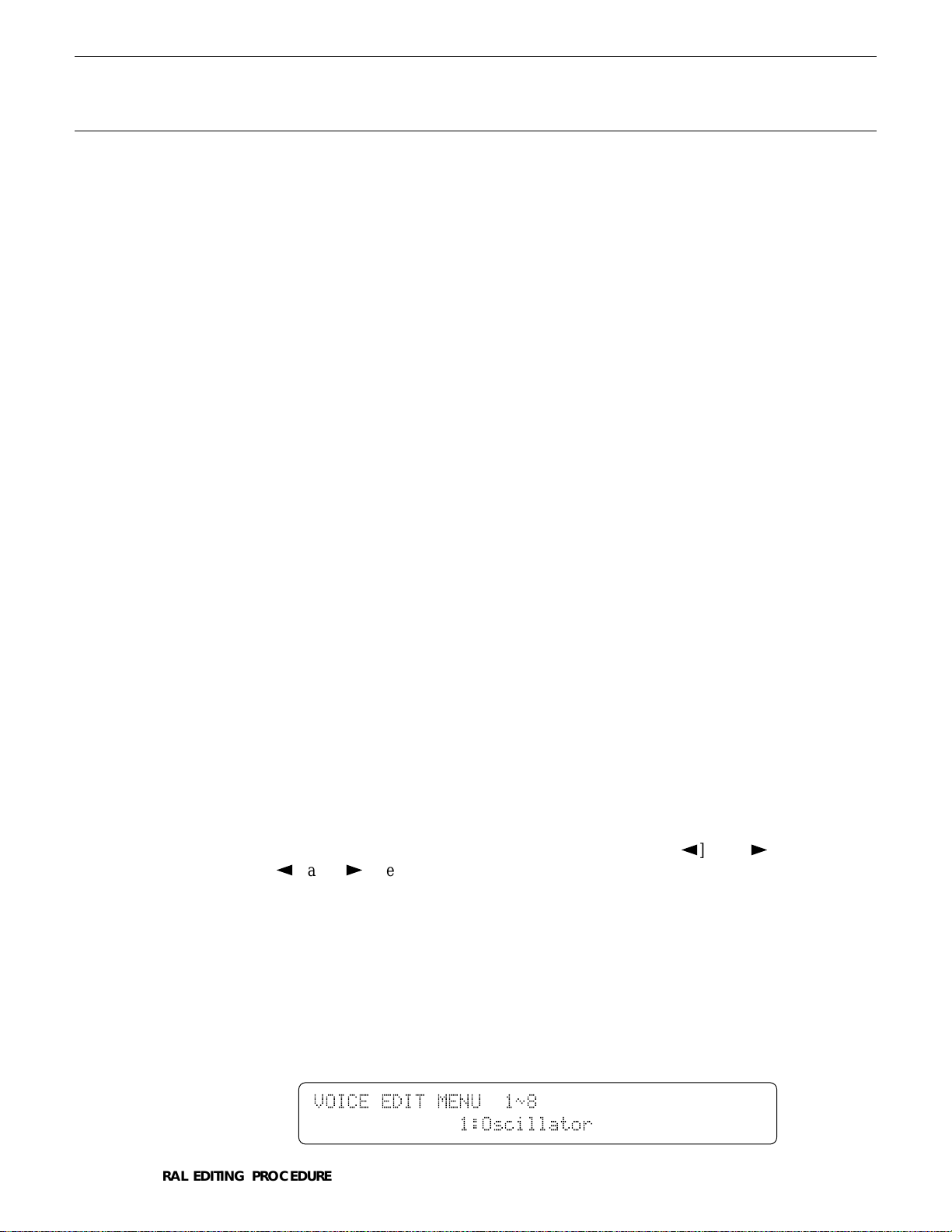
An alternative method is to use the [MENU] key. If you press the [MENU]
key ion the VOICE EDIT mode, for example, you’ll see a display something
like this:
VOICE`EDIT`MENU``1ø8````````````````````
`````````````1:Oscillator```````````````
8
GENERAL EDITING PROCEDURE
Page 10
From this display you can use either the data entry dial or the [-1] and [+1]
The illustrations here are not available.
keys to directly select any of the 8 available functions, then press the [ENTER/
YES] key to actually select the specified function.
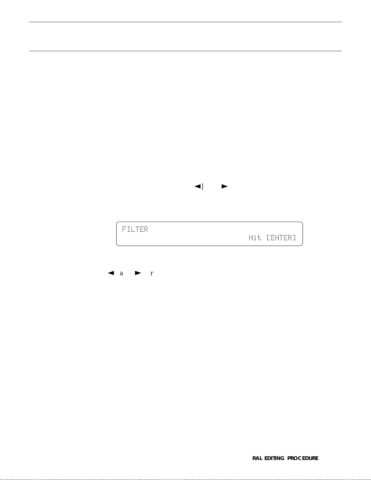
In some cases the PAGE [k] and [l] or [MENU] keys will take you to
another entry screen. If you select “3: Filter” after pressing the [MENU] key in
the VOICE EDIT mode, and then press [ENTER/YES], you’ll see the following
display:
FILTER``````````````````````````````````
`````````````````````````````Hit`[ENTER]
“Hit [ENTER]” will be flashing. In this case press [ENTER/YES] again to
access the filter functions. Once in the filter “sub-mode” you can use the PAGE
[k] and [l] or [MENU] keys to select the various filter functions, as described above. When you have finished with the filter functions, press [EXIT/
NO] to return to the normal VOICE EDIT mode.
GENERAL EDITING PROCEDURE
9
Page 11
■ Selecting & Editing Parameters
The illustrations here are not available.
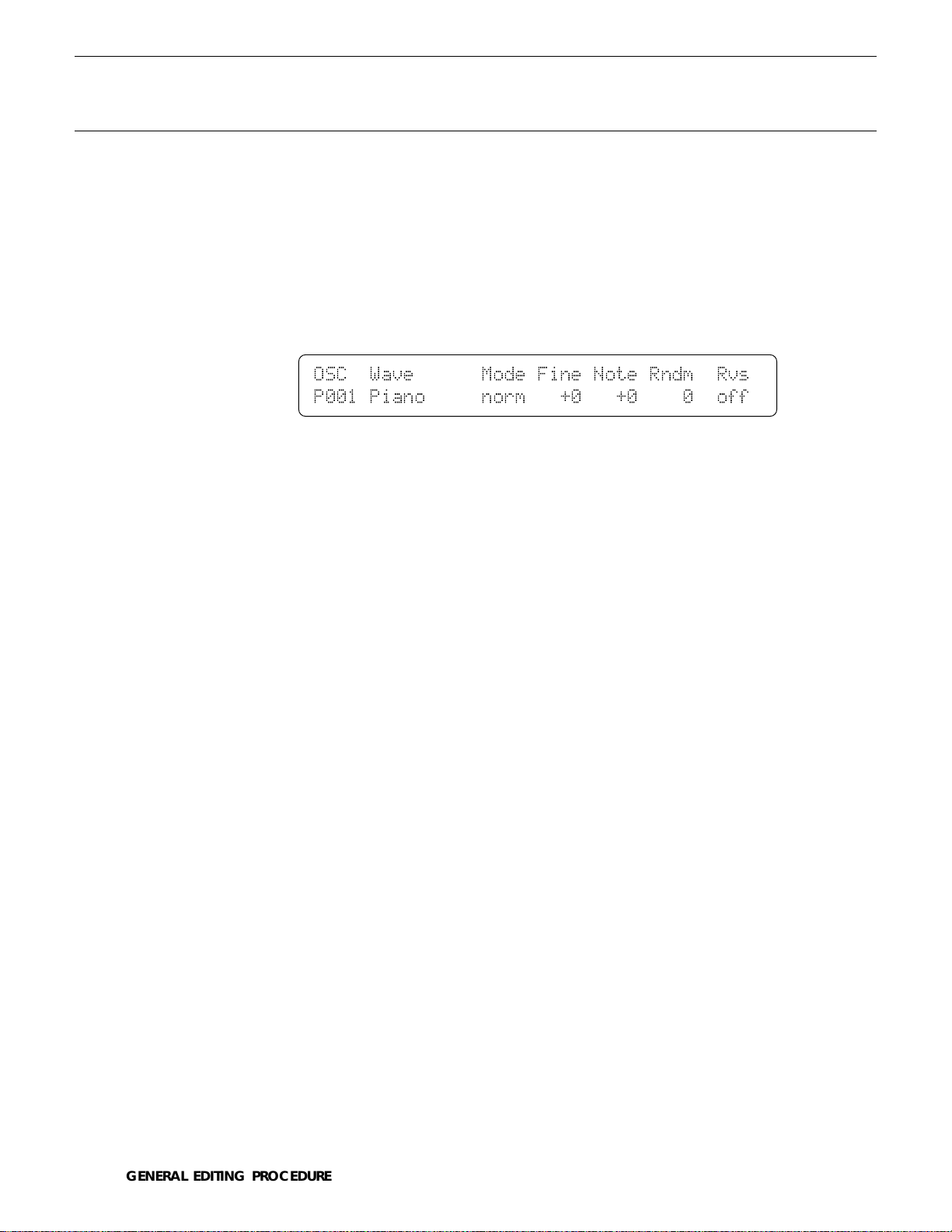
Most SY85 edit screens contain several parameters that can be selected and
edited. In most cases you can simply operate the continuous slider immediately
below the parameter you want to edit on the display. Operating a slider automatically moves the underline cursor to the corresponding parameter. In the
example below, for example (this is the VOICE EDIT mode Oscillator screen),
the [CS5] slider can be used to adjust the “Fine” parameter.
OSC``Wave``````Mode`Fine`Note`Rndm``Rvs`
P001`Piano`````norm```+0```+0````0``off`
The parameters can also be edited by first moving the cursor to the required
parameter by pressing the corresponding function key ([F7], for example, would
select the “Rndm” parameter in the above display), and then by using either the
data entry dial or the [-1] and [+1] keys to adjust the parameter’s value.
In some special cases you’ll also use the function keys as parameter
“switches,” and the [SHIFT] key is sometimes called into play to access secondary functions. Such exceptions are described in the appropriate sections of
the manual.
10
GENERAL EDITING PROCEDURE
Page 12
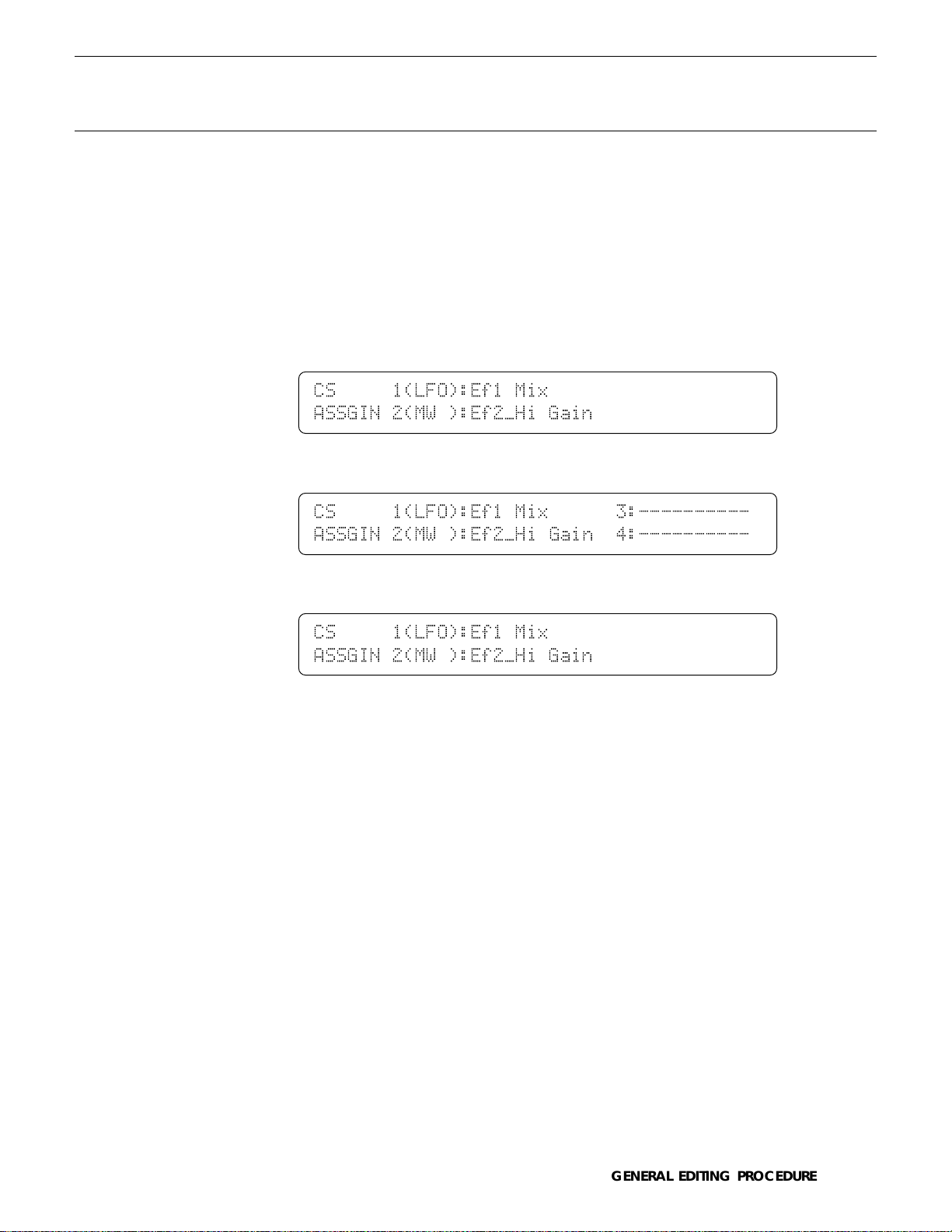
■ Controller Assignment Display
It is possible to assign a wide range of parameters to be controlled by the
[CS1] through [CS4] sliders when playing in the VOICE or PERFORMANCE
PLAY modes. Since it is easy to forget what parameters have been assigned to
which sliders, the SY85 features a controller assignment display that can be
selected temporarily by pressing the [SHIFT] key in the VOICE or PERFORMANCE PLAY mode.
● PERFORMANCE PLAY mode
CS`````1(LFO):Ef1`Mix```````````````````
ASSGIN`2(MW`):Ef2»Hi`Gain```````````````
● VOICE PLAY mode
CS`````1(LFO):Ef1`Mix``````3:----------`
ASSGIN`2(MW`):Ef2»Hi`Gain``4:----------`
● DRUM VOICE PLAY mode
CS`````1(LFO):Ef1`Mix```````````````````
ASSGIN`2(MW`):Ef2»Hi`Gain```````````````
This display shows the names of the parameters assigned to sliders [CS1]
through [CS4] for the current voice or performance combination, so you can
take a quick peek to refresh your memory even while playing.
GENERAL EDITING PROCEDURE
11
Page 13

Page 14

PERFORMANCE EDIT MODE
Page 15
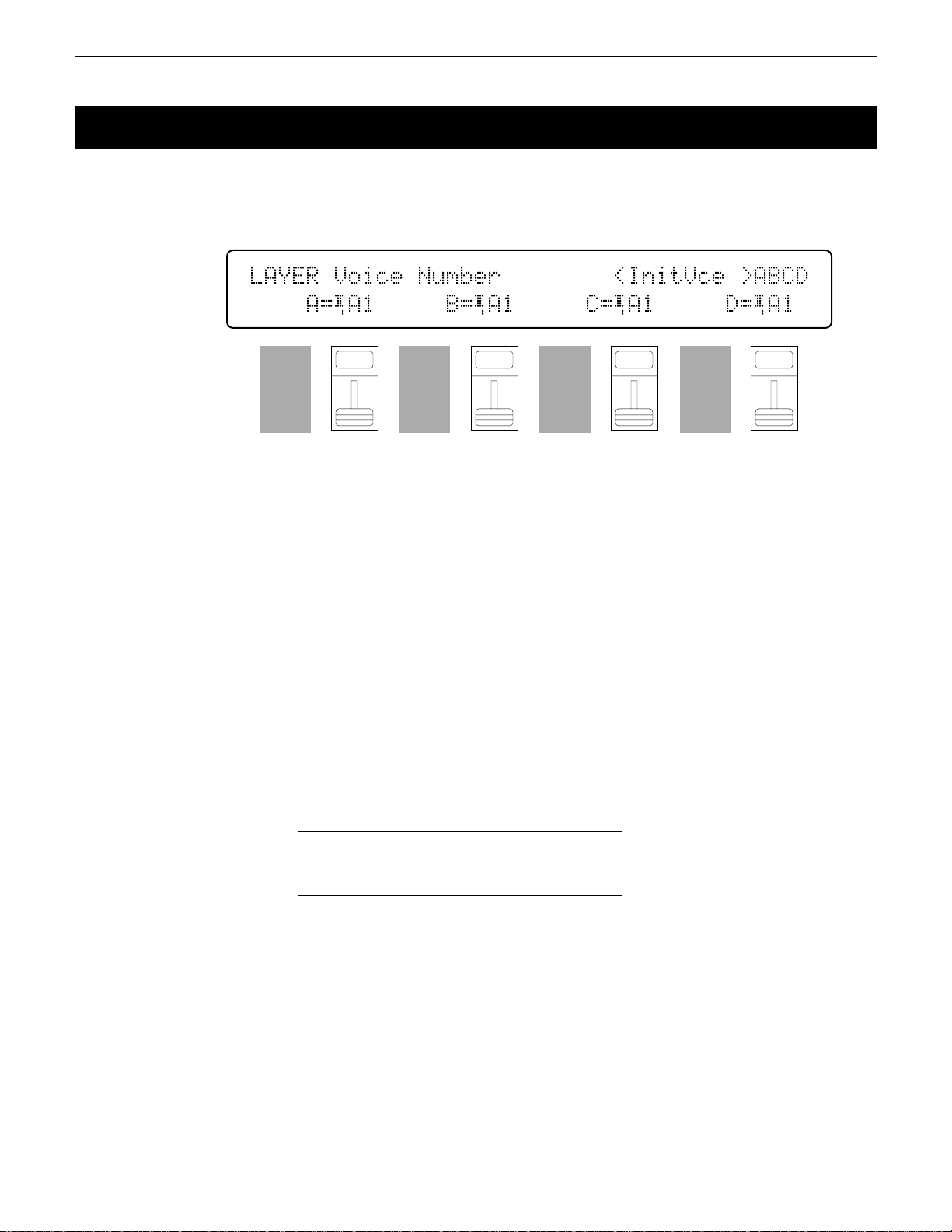
1: VOICE NUMBER
[PERFORMANCE] → [EDIT] → [MENU] → 1:Layer → [ENTER/YES] → [ENTER/YES] →
→ [MENU] → 1:Voice Number → [ENTER/YES]
SY85 performance combinations can have up to four voices assigned to different
“layers” — A, B, C and D. This screen lets you assign voices to the layers.
LAYER`Voice`Number````````<InitVce`>ABCD
````A=¡A1`````B=¡A1`````C=¡A1`````D=¡A1
F1
CS1
F2
CS2
F3
CS3
F4
CS4
Voice Number A, B, C, D
Range: off, A1 … H7 (internal & card)
Controls: MEMORY, GROUP, PROGRAM, [CS2], [CS4], [CS6], [CS8],
[-1] [+1], Dial
After moving the cursor to the layer you want to edit by pressing the [F2],
[F4], [F6] or [F8] function key, use the [INTERNAL 1], [INTERNAL 2], and
[CARD] keys to select the memory area from which the voice is to be selected,
and then use the GROUP and PROGRAM keys to select the voice. Voices
within the selected memory bank can also be selected directy for each layer by
the [CS2], [CS4], [CS6], and [CS8] keys. Internal and card voices cannot be
mixed.
The voices can individually turned on or off by using the [-] (off) and [+]
(on) keys while holding the [SHIFT] key.
The name of the currently selected voice is shown in the upper right corner
of the display. The characters “ABCD” to the right of the voice name indicate
the status of each voice:
F5
CS5
F6
CS6
F7
CS7
F8
CS8
14
• Capital letter = voice on.
• Lower-case letter = voice muted.
• “-” = voice is off.
For example, “Ab-D” indicates that voices A and D are on, voice B is
muted, and voice C is off.
PERFORMANCE EDIT MODE / 1:Layer
Page 16
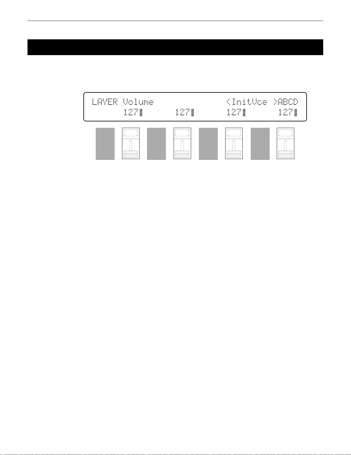
2: VOLUME
[PERFORMANCE] → [EDIT] → [MENU] → 1:Layer → [ENTER/YES] → [ENTER/YES] →
→ [MENU] → 2:Volume → [ENTER/YES]
For optimum balance between the voices in a performance combination, this
screen allows the volume of each voice to be adjusted individually.
LAYER`Volume``````````````<InitVce`>ABCD
``````127ƒ``````127ƒ``````127ƒ``````127ƒ
F1
CS1
The name of the currently selected voice/layer is shown in the upper right
corner of the display. The characters “ABCD” to the right of the voice name
indicate the status of each voice: a capital letter if the voice is on, a lower-case
letter if the voice is muted, and a dash if the voice is off.
Volume
Range: 0 … 127
Controls: [CS2], [CS4], [CS6], [CS8], [-1] [+1], Dial
Use the [CS2], [CS4], [CS6], and [CS8] sliders to adjust the volume levels
of the A, B, C, and D layer voices, respectively. A setting of “0” produces no
sound, while a setting of “127” produces maximum volume. The vertical bar
graphs next to each parameter provide a visual indication of volume levels —
the longer the bar the higher the volume. Voices that are turned off are indicated by “----” on the display.
F2
CS2
F3
CS3
F4
CS4
F5
CS5
F6
CS6
F7
CS7
F8
CS8
15PERFORMANCE EDIT MODE / 1:Layer
Page 17
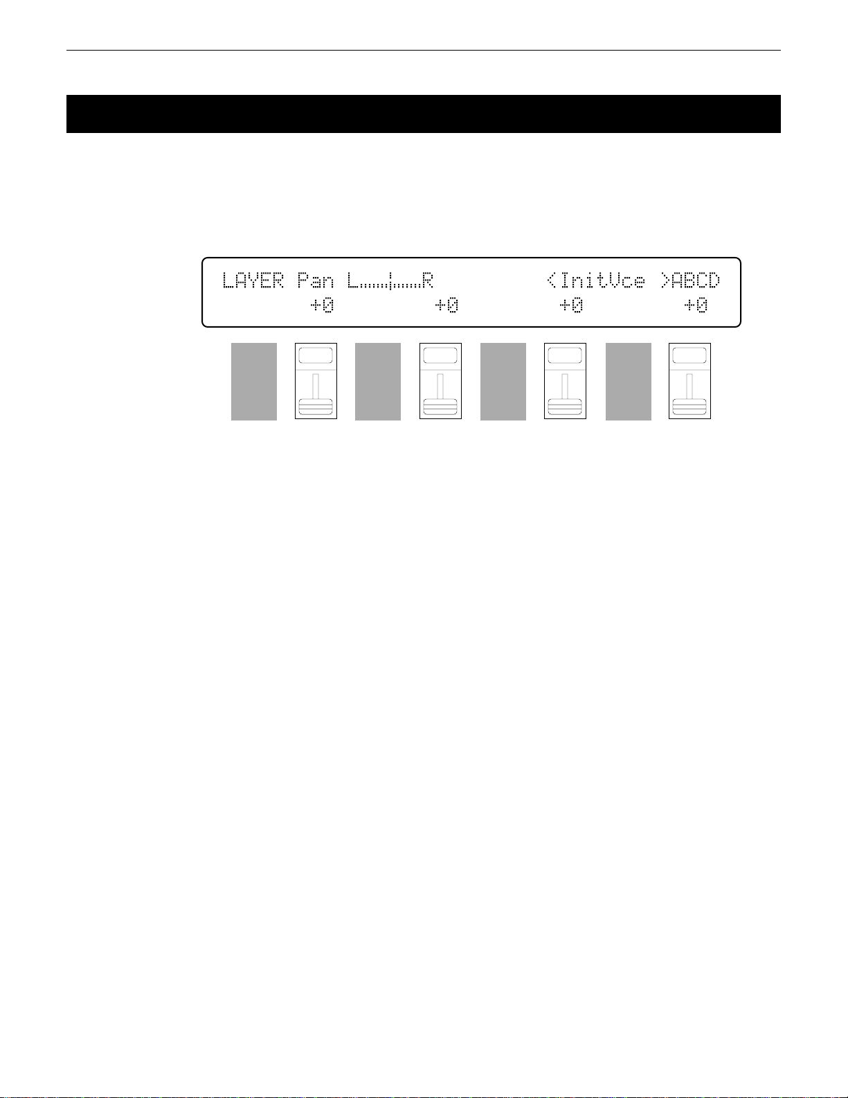
3: PAN
[PERFORMANCE] → [EDIT] → [MENU] → 1:Layer → [ENTER/YES] → [ENTER/YES] →
→ [MENU] → 3:Pan → [ENTER/YES]
In multi-layer performance combinations, interesting stereo effects can be produced by placing the output from different layers at different locations in the stereo
sound field. The parameters in this screen determine the position in the stereo sound
field in which the sound from each active layer will be heard (left to right).
LAYER`Pan`L¯¯Æ¯¯R`````````<InitVce`>ABCD
```````+0````````+0````````+0````````+0`
Pan
F1
CS1
F2
CS2
F3
CS3
F4
CS4
F5
CS5
F6
CS6
F7
CS7
F8
CS8
The name of the currently selected voice/layer is shown in the upper right
corner of the display. The characters “ABCD” to the right of the voice name
indicate the status of each voice: a capital letter if the voice is on, a lower-case
letter if the voice is muted, and a dash if the voice is off.
Range: -31 … +31
Controls: [CS2], [CS4], [CS6], [CS8], [-1] [+1], Dial
Use the [CS2], [CS4], [CS6], and [CS8] sliders to adjust the pan positions
of the A, B, C, and D layer voices, respectively. Minus values represent panning to the left, and positive values represent panning to the right. “0” positions the sound of the selected layer in the center of the stereo sound field.
Voices that are turned off are indicated by “---” on the display. The upper line
of the display also shows a graphic representation of the stereo sound field
with “L” representing “left” and “R” representing “right.” As you change the
pan value the vertical bar will appear at the corresponding position on the
graphic display.
16
PERFORMANCE EDIT MODE / 1:Layer
Page 18
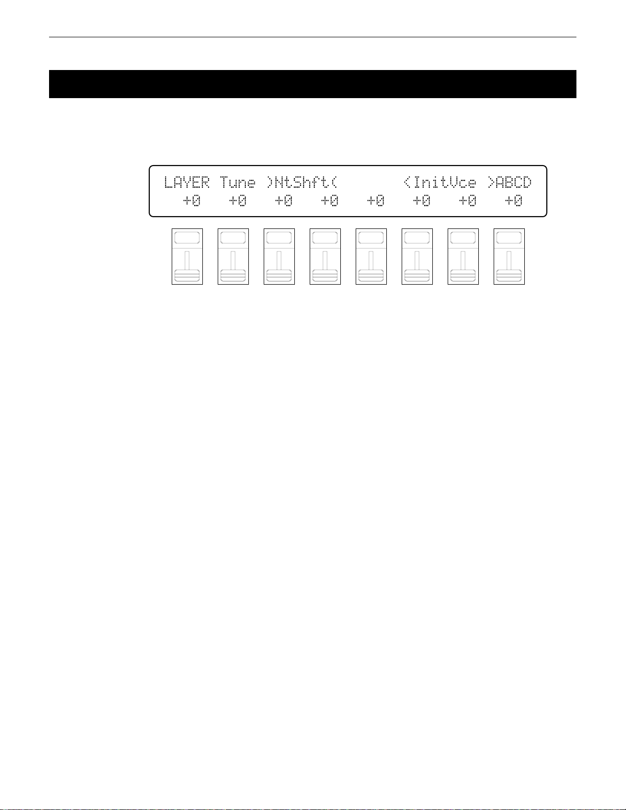
4: TUNE
[PERFORMANCE] → [EDIT] → [MENU] → 1:Layer → [ENTER/YES] → [ENTER/YES] →
→ [MENU] → 4:Tune → [ENTER/YES]
More than just simple tuning, the note shift and fine tune parameters make it
possible to create harmony and voice-thickening detune effects between layers.
LAYER`Tune`)NtShft(```````<InitVce`>ABCD
``+0```+0```+0```+0```+0```+0```+0```+0`
F1
CS1
F2
CS2
F3
CS3
The name of the currently selected voice/layer is shown in the upper right
corner of the display. The characters “ABCD” to the right of the voice name
indicate the status of each voice: a capital letter if the voice is on, a lower-case
letter if the voice is muted, and a dash if the voice is off.
NtShft (Note shift)
Range: -63 … +63
Controls: [CS1], [CS3], [CS5], [CS7], [-1] [+1], Dial
Individually shifts the pitch of each active element up or down in semitone
steps.
Use the [CS1], [CS3], [CS5], and [CS7] sliders to shift the pitch of the A,
B, C, and D layer voices, respectively. A setting of “-12,” for example, shifts
the pitch of the selected layer down by one octave; a setting of “+4” shifts the
pitch up by a major third.
The Note Shift parameter can be used to transpose a voice to its most
useful range, or to create harmony (intervals) between different layers in a
performance combination.
Voices that are turned off are indicated by “---” on the display.
F4
CS4
F5
CS5
F6
CS6
F7
CS7
F8
CS8
Fine (Fine tuning)
Range: -7 … +7
Controls: [CS2], [CS4], [CS6], [CS8], [-1] [+1], Dial
Allows slight upward or downward pitch adjustment of each active element.
Use the [CS2], [CS4], [CS6], and [CS8] sliders to fine tune the A, B, C,
and D layer voices, respectively.
The maximum minus setting of “-7” produces a downward pitch shift of
approximately 2 cents (a “cent” is 1/100th of a semitone), and the maximum
plus setting of “+7” produces an upward pitch shift of approximately 2 cents. A
setting of “0” produces no pitch change.
The Fine parameter allows different layers in a performance combination to
be slightly detuned in relation to each other, thereby “thickening” the overall
sound.
Voices that are turned off are indicated by “--” on the display.
17PERFORMANCE EDIT MODE / 1:Layer
Page 19
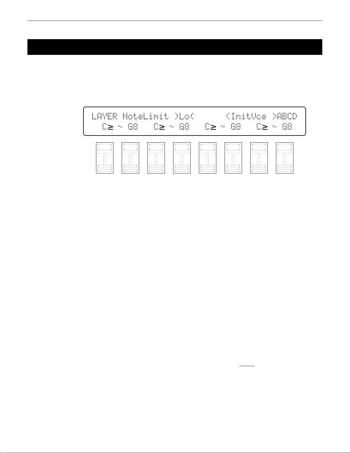
5: NOTE LIMIT
[PERFORMANCE] → [EDIT] → [MENU] → 1:Layer → [ENTER/YES] → [ENTER/YES] →
→ [MENU] → 5:Note Limit → [ENTER/YES]
The low and high note limit parameters make it possible to create a range of split
keyboard effects using the performance layers. You could have two layers on either
side of a single split point, a four-way split keyboard, or any other possible combination.
LAYER`NoteLimit`)Lo(``````<InitVce`>ABCD
``C≥`ø`G8```C≥`ø`G8```C≥`ø`G8```C≥`ø`G8
F1
CS1
F2
CS2
F3
CS3
The name of the currently selected voice/layer is shown in the upper right
corner of the display. The characters “ABCD” to the right of the voice name
indicate the status of each voice: a capital letter if the voice is on, a lower-case
letter if the voice is muted, and a dash if the voice is off.
Lo (Low note limit)
Range: C-2 … G8
Controls: [CS1], [CS3], [CS5], [CS7], [-1] [+1], Dial,
[SHIFT]+keyboard
Individually sets the low note limit for each active layer (the lowest note
that each layer will produce).
Use the [CS1], [CS3], [CS5], and [CS7] sliders to set the low note limits of
the A, B, C, and D layer voices, respectively. It is also possible to press the
desired note on the keyboard while holding the [SHIFT] key.
The C-2 to G8 range of this parameter covers a full 10-1/2 octaves. “C3”
corresponds to “middle C” on a keyboard.
This parameter, in conjunction with the High Note Limit parameter described below, allows the sound from a layer to be limited to a specific region
of the keyboard. If the Low Note Limit is set to C3 and the High Note Limit
for the same layer is set to C4, for example, the sound from that layer will
only be produced between C3 and C4 — the octave immediately above middle
C. This makes it simple to produce split voices.
If the High Note Limit is set to a note that is
Limit for the same layer, the notes between the high and low limits will not
sound.
Voices that are turned off are indicated by “---” on the display.
F4
CS4
F5
CS5
F6
CS6
F7
CS7
F8
CS8
lower than the Low Note
18
PERFORMANCE EDIT MODE / 1:Layer
Page 20

Hi (High note limit)
Range: C-2 … G8
Controls: [CS2], [CS4], [CS6], [CS8], [-1] [+1], Dial,
[SHIFT]+keyboard
Individually sets the high note limit for each active layer (the highest note
that each layer will produce).
Use the [CS2], [CS4], [CS6], and [CS8] sliders to set the high note limits
of the A, B, C, and D layer voices, respectively. It is also possible to press the
desired note on the keyboard while holding the [SHIFT] key.
See the “Lo” parameter, above, for more details.
19PERFORMANCE EDIT MODE / 1:Layer
Page 21
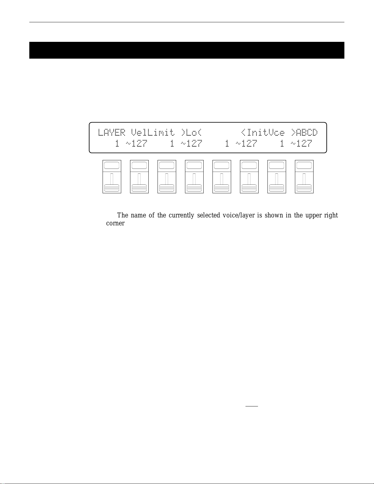
6: VELOCITY LIMIT
[PERFORMANCE] → [EDIT] → [MENU] → 1:Layer → [ENTER/YES] → [ENTER/YES] →
→ [MENU] → 6:VelocityLimit → [ENTER/YES]
The high and low velocity limit parameters make it possible to produce a range of
“velocity switching” effects in which different layers of a performance combination
are set up to produce sound only when the keyboard is played at a certain velocity.
You could, for example, produce a flute sound by playing softly, and a horn sound
by playing harder.
LAYER`VelLimit`)Lo(```````<InitVce`>ABCD
```1`ø127````1`ø127````1`ø127````1`ø127`
F1
CS1
F2
CS2
F3
CS3
The name of the currently selected voice/layer is shown in the upper right
corner of the display. The characters “ABCD” to the right of the voice name
indicate the status of each voice: a capital letter if the voice is on, a lower-case
letter if the voice is muted, and a dash if the voice is off.
Lo (Low velocity limit)
Range: 1 … 127
Controls: [CS1], [CS3], [CS5], [CS7], [-1] [+1], Dial,
[SHIFT]+keyboard
Sets the lowest velocity value for a range of velocity values over which
each active layer will produce output.
Use the [CS1], [CS3], [CS5], and [CS7] sliders to set the low velocity
limits of the A, B, C, and D layer voices, respectively. It is also possible to
play any note on the keyboard at the desired velocity while holding the
[SHIFT] key.
Every note played on the keyboard (or external MIDI controller) produces a
“velocity” value that tells the tone generator how hard the note has been
played. The range of MIDI velocity values is from 1 to 127 — thus the 1 ...
127 range of this parameter.
The Low Velocity Limit parameter, in conjunction with the High Velocity
Limit parameter described below, makes it possible to specify a range of velocity values over which the selected layer will produce sound. You could, for
example, set Low Velocity Limit to “60” and High Velocity Limit to “127.”
This would cause that layer to produce output
between 60 and 127 was received — i.e. when a fairly loud note is played. A
second layer could then be set to produce output only when velocity values
below 60 are received, so that completely different sounds are produced on soft
and loud notes.
Voices that are turned off are indicated by “---” on the display.
F4
CS4
F5
CS5
F6
CS6
F7
CS7
F8
CS8
only when a velocity value
20
PERFORMANCE EDIT MODE / 1:Layer
Page 22

Hi (High velocity limit)
Range: 1 … 127
Controls: [CS2], [CS4], [CS6], [CS8], [-1] [+1], Dial,
[SHIFT]+keyboard
Sets the highest velocity value for a range of velocity values over which
each active layer will produce output.
Use the [CS2], [CS4], [CS6], and [CS8] sliders to set the high velocity
limits of the A, B, C, and D layer voices, respectively. It is also possible to
play any note on the keyboard at the desired velocity while holding the
[SHIFT] key.
See the “Lo” parameter, above, for more details.
21PERFORMANCE EDIT MODE / 1:Layer
Page 23

7: CS ENABLE
[PERFORMANCE] → [EDIT] → [MENU] → 1:Layer → [ENTER/YES] → [ENTER/YES] →
→ [MENU] → 7:CS Enable → [ENTER/YES]
The CS3 and CS4 sliders can be used to control the level of individual layers or
specified groups of layers in the performance play mode. This screen specifies which
slider controls which layers.
LAYER`CS`Enable`)CS4(`````<InitVce`>ABCD
`off``off``off``off``off``off``off``off
F1
CS1
The name of the currently selected voice/layer is shown in the upper right
corner of the display. The characters “ABCD” to the right of the voice name
indicate the status of each voice: a capital letter if the voice is on, a lower-case
letter if the voice is muted, and a dash if the voice is off.
CS3 Enable
Range: on, off
Controls: [CS1], [CS3], [CS5], [CS7], [-1] [+1], Dial
The [CS1], [CS3], [CS5], and [CS7] sliders turn CS3 control of layers A,
B, C, and D on or off, respectively.
Voices that are turned off and are not available for editing are indicated by
“---” on the display.
CS4 Enable
Range: on, off
Controls: [CS2], [CS4], [CS6], [CS8], [-1] [+1], Dial
F2
CS2
F3
CS3
F4
CS4
F5
CS5
F6
CS6
F7
CS7
F8
CS8
22
The [CS2], [CS4], [CS6], and [CS8] sliders turn CS4 control of layers A,
B, C, and D on or off, respectively.
Voices that are turned off and are not available for editing are indicated by
“---” on the display.
PERFORMANCE EDIT MODE / 1:Layer
Page 24
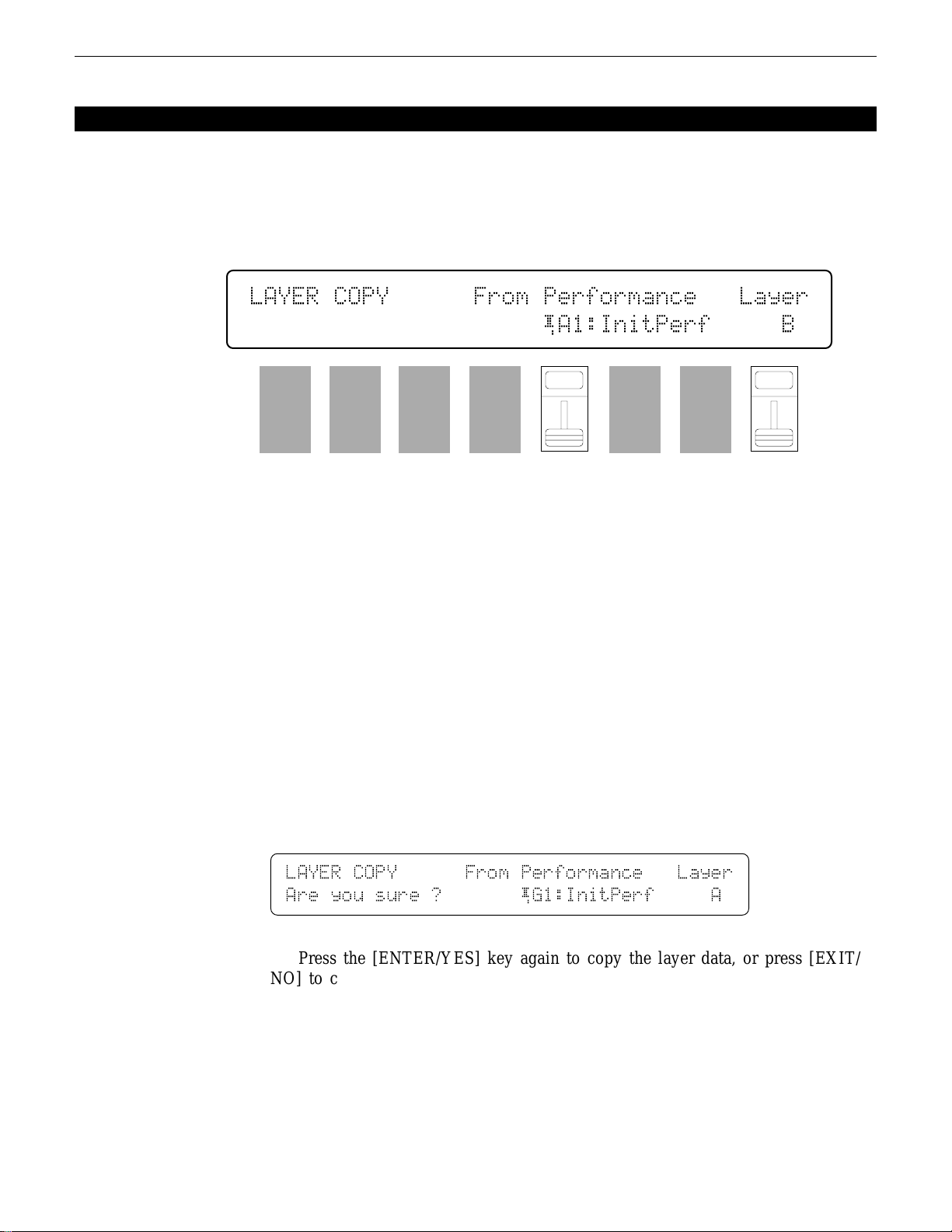
LAYER DATA COPY
[PERFORMANCE] → [EDIT] → [MENU] → 1:Layer → [ENTER/YES] → [COPY]
This function facilitates performance editing by allowing the layer parameters
from any layer in any other performance (the “source” performance) to be copied to
the current layer. You can copy a layer setup that is close to the type you want, then
edit it to produce the required sound.
LAYER`COPY``````From`Performance```Layer
`````````````````````¡A1:InitPerf`````B`
F1
CS1
F2
CS2
F3
CS3
From Performance
Range: Any INTERNAL or CARD performance
Controls: MEMORY, GROUP, PROGRAM, [CS5], [-1] [+1], Dial
Layer
Range: A, B, C, D
Controls: [CS8], [-1] [+1], Dial
Use the [INTERNAL 1], [INTERNAL 2], and [CARD] MEMORY keys to
select the memory area from which the source performance is to be selected.
Use the GROUP keys to select the source performance bank, then use the
PROGRAM keys to select the source performance number. The [CS5] slider
and other data entry controls can also be used to select the source performance
number. Use the [CS8] slider to select the source layer.
Once the source performance and layer has been selected, press the [ENTER/YES] key. “Are you sure?” will appear on the display.
F4
CS4
F5
CS5
F6
CS6
F7
CS7
F8
CS8
LAYER`COPY``````From`Performance```Layer
Are`you`sure`?```````¡G1:InitPerf`````A
Press the [ENTER/YES] key again to copy the layer data, or press [EXIT/
NO] to cancel the copy operation. Once the copy operation has finished, “Completed!” will appear on the display briefly, then the display will return to the
layer edit mode.
23PERFORMANCE EDIT MODE / 1:Layer
Page 25
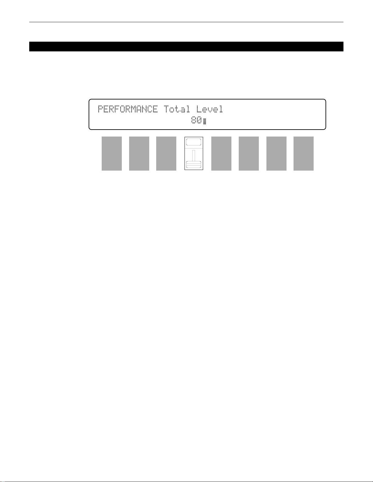
PERFORMANCE TOTAL LEVEL
[PERFORMANCE] → [EDIT] → [MENU] → 2:Total Level → [ENTER/YES]
This parameter sets the overall volume of the current performance combination in
relation to the others, making it possible to match levels for smooth transition when
switching between performance combinations.
PERFORMANCE`Total`Level``
`````````````````80ß
F1
CS1
Total Level
Range: 0 … 127
Controls: [CS4], [-1] [+1], Dial
Adjusts the volume of the current performance.
A setting of “0” produces no sound while a setting of “127” produces
maximum volume. A bar graph to the right of the parameter provides a visual
indication of volume level — the longer the bar, the higher the volume.
F2
CS2
F3
CS3
F4
CS4
F5
CS5
F6
CS6
F7
CS7
F8
CS8
24 PERFORMANCE EDIT MODE / 2:Volume
Page 26
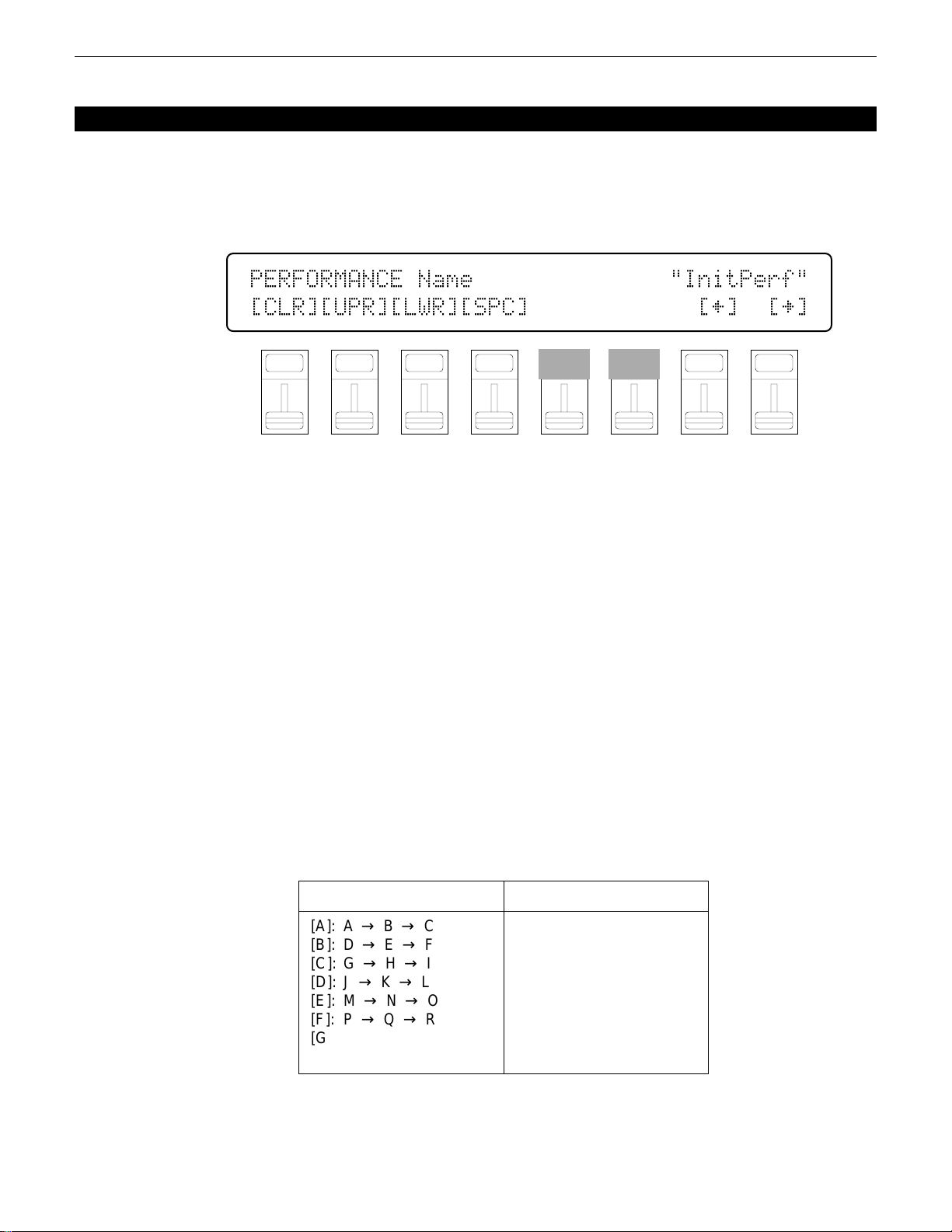
PERFORMANCE NAME
[PERFORMANCE] → [EDIT] → [MENU] → 3:Name → [ENTER/YES]
Your original performance combinations should naturally have original names.
This function can be used to assign a name of up to 8 characters to the current
performance.
PERFORMANCE`Name``````````````"InitPerf"
[CLR][UPR][LWR][SPC]````````````[†]``[¥]
CS1
Name
Range: See character list, below
Controls: GROUP, PROGRAM, [F1] … [F4], [F7], [F8],
[F8] function key to move the cursor to the right. Use the GROUP and PROGRAM keys to input a character at the cursor position. Each GROUP or PROGRAM key selects the three characters printed above it in sequence. It is also
possible to use the [-1] and [+1] keys or dial to scroll through the available
characters (see list below).
corresponding character position: [CS1] selects the first character, [CS2] selects
the second character, and so on.
the entire name, [F2] selects upper-case characters for GROUP and PROGRAM
key entry, [F3] selects lower-case characters for GROUP and PROGRAM key
entry, and [F4] inserts a space at the cursor position.
F1
F2
CS2
F3
CS3
F4
CS4
F5
CS5
F6
CS6
F7
CS7
F8
CS8
[CS1] … [CS8], [-1] [+1], Dial
Assigns a name of up to 8 characters to the current performance.
Use the [F7] function key to move the character cursor to the left, and the
The sliders, [CS1] through [CS8], independently select characters for the
The first four function keys also perform important functions: [F1] clears
GROUP key
[A]: A → B → C
[B]: D → E → F
[C]: G → H → I
[D]: J → K → L
[E]: M → N → O
[F]: P → Q → R
[G]: S → T → U
[H]: V → W → X
PROGRAM key
[1]: Y → Z → 0
[2]: 1 → 2 → 3
[3]: 4 → 5 → 6
[4]: 7 → 8 → 9
[5]: * → & → _
[6]: / → . → ,
[7]: ’ → ! → ?
[8]: # → : → ;
25PERFORMANCE EDIT MODE / 3:Name
Page 27
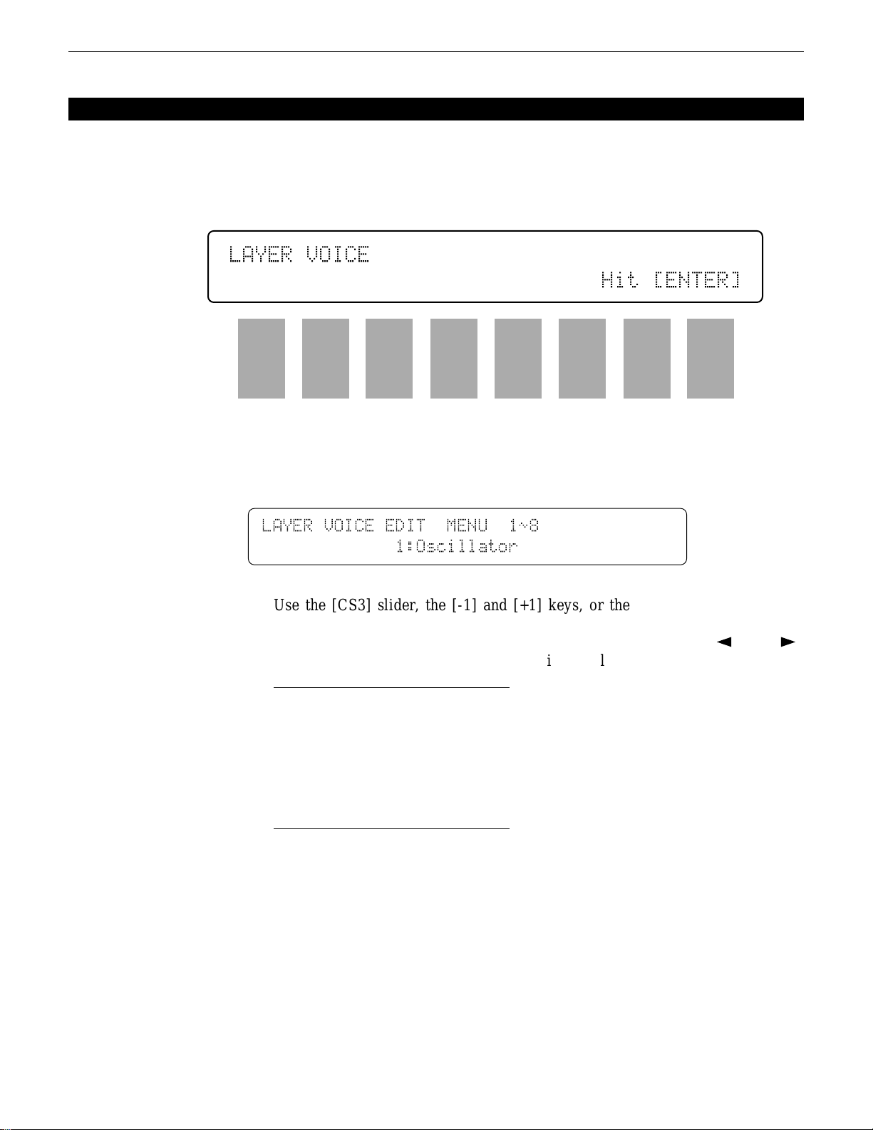
LAYER VOICE EDIT MENU
[PERFORMANCE] → [EDIT] → [MENU] → 4:Layer Voice → [ENTER/YES]
The Layer Voice Edit menu allows you to access any of the voice edit parameters
for the voice assigned to the currently selected performance layer, without having to
leave the performance edit mode.
LAYER`VOICE`
`````````````````````````````Hit`[ENTER]
F1
CS1
F2
CS2
F3
CS3
F4
CS4
F5
CS5
F6
CS6
F7
CS7
F8
CS8
Press [ENTER/YES] from the entry display (above) to access the layer
voice edit menu.
LAYER`VOICE`EDIT``MENU``1ø8
`````````````1:Oscillator
Use the [CS3] slider, the [-1] and [+1] keys, or the data entry dial to select
the desired voice edit screen, then press [ENTER/YES] to jump to selected
screen. Other voice edit screens can then be selected by using the [k] and [l]
keys. The available voice edit screens are listed below:
1: Oscillator
2: Amplitude EG
3: Filter
4: Pitch EG
5: LFO
6: Controller
7: VOICE Total Level
8: VOICE Name
26
While editing the voice parameters in voice edit screens 2 through 7, above,
the PROGRAM keys [1] through [4] (LAYER SELECT A, B, C, and D) can be
used to select a different layer for editing. PROGRAM keys [5] through [8] can
also be used for layer muting.
Press [EXIT/NO] to return to the performance edit mode when you’re
finished with the voice edit parameters. Refer to pages 58 through 95 in the
“Voice Edit Mode” section for details on the voice edit parameters.
PERFORMANCE EDIT MODE / 4:Layer Voice
Page 28
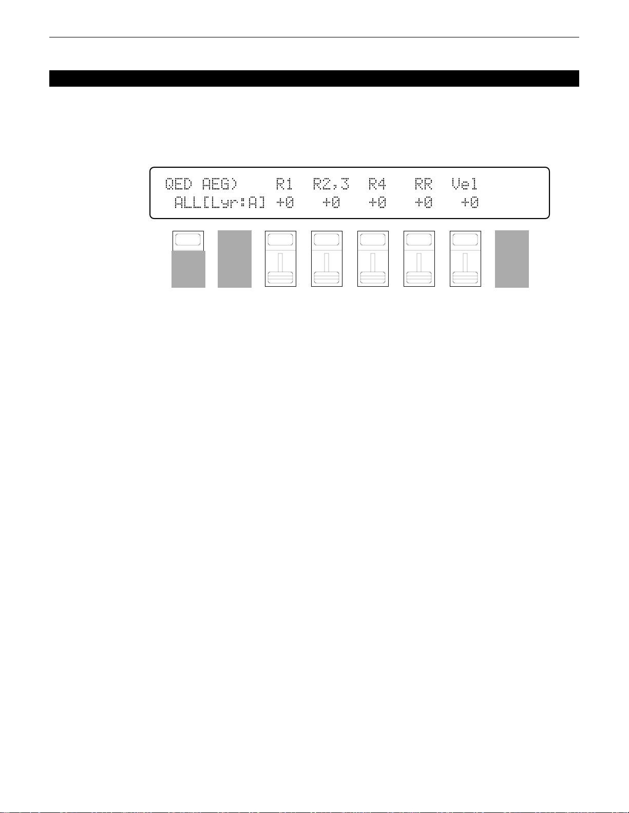
1: AMPLITUDE EG OFFSET
[PERFORMANCE] → [QUICK EDIT] → [MENU] → 1:AEG Offset → [ENTER/YES]
These parameters allow the amplitude envelopes of the voices assigned to each
layer to be modified to some degree. The actual amplitude EG of the voices are not
affected, these “offset” values are only effective in the performance mode.
QED`AEG)````R1``R2,3``R4```RR``Vel
`ALL[Lyr:A]`+0```+0```+0```+0```+0
F1
CS1
F2
CS2
Use PROGRAM keys [1] through [4] (LAYER SELECT A, B, C, and D) to
select the layer to be edited.
Hold the [F1] function key (“ALL”) while editing any of the following
parameters to change its value by the same amount for all layers simultaneously.
R1 (Attack rate)
Range: -63 … +63
Controls: [CS3], [-1] [+1], Dial
Modifies the “R1” parameter of the voice amplitude EG — see page 60.
Plus (+) values produce a faster attack rate while minus (-) values produce a
slower attack rate.
No matter how much offset is applied, the minimum and maximum EG
attack rates cannot be exceeded.
F3
CS3
F4
CS4
F5
CS5
F6
CS6
F7
CS7
F8
CS8
R2,3 (Decay 1 rate)
Range: -63 … +63
Controls: [CS4], [-1] [+1], Dial
Modifies the “R2” and “R3” parameters of the voice amplitude EG — see
page 60. Plus (+) values produce a faster decay rate while minus (-) values
produce a slower decay rate.
No matter how much offset is applied, the minimum and maximum EG
decay rates cannot be exceeded.
R4 (Decay 2 rate)
Range: -63 … +63
Controls: [CS5], [-1] [+1], Dial
Modifies the “R4” parameter of the voice amplitude EG — see page 60.
Plus (+) values produce a faster decay rate while minus (-) values produce a
slower decay rate.
No matter how much offset is applied, the minimum and maximum EG
decay rates cannot be exceeded.
27PERFORMANCE EDIT MODE / QUICK EDIT
Page 29

RR (Release rate)
Range: -63 … +63
Controls: [CS6], [-1] [+1], Dial
Modifies the “RR” parameter of the voice amplitude EG — see page 60.
Plus (+) values produce a faster release rate while minus (-) values produce a
slower release rate.
No matter how much offset is applied, the minimum and maximum EG
release rates cannot be exceeded.
Vel (Velocity sensitivity)
Range: -14 ... +14
Controls: [CS7], [-1] [+1], Dial
Modifies the amplitude EG velocity sensitivity setting (see page 63). Plus
“+” settings increase sensitivity while minus “-” settings reduce sensitivity.
No matter how much offset is applied, the minimum and maximum velocity
values cannot be exceeded.
28 PERFORMANCE EDIT MODE / QUICK EDIT
Page 30
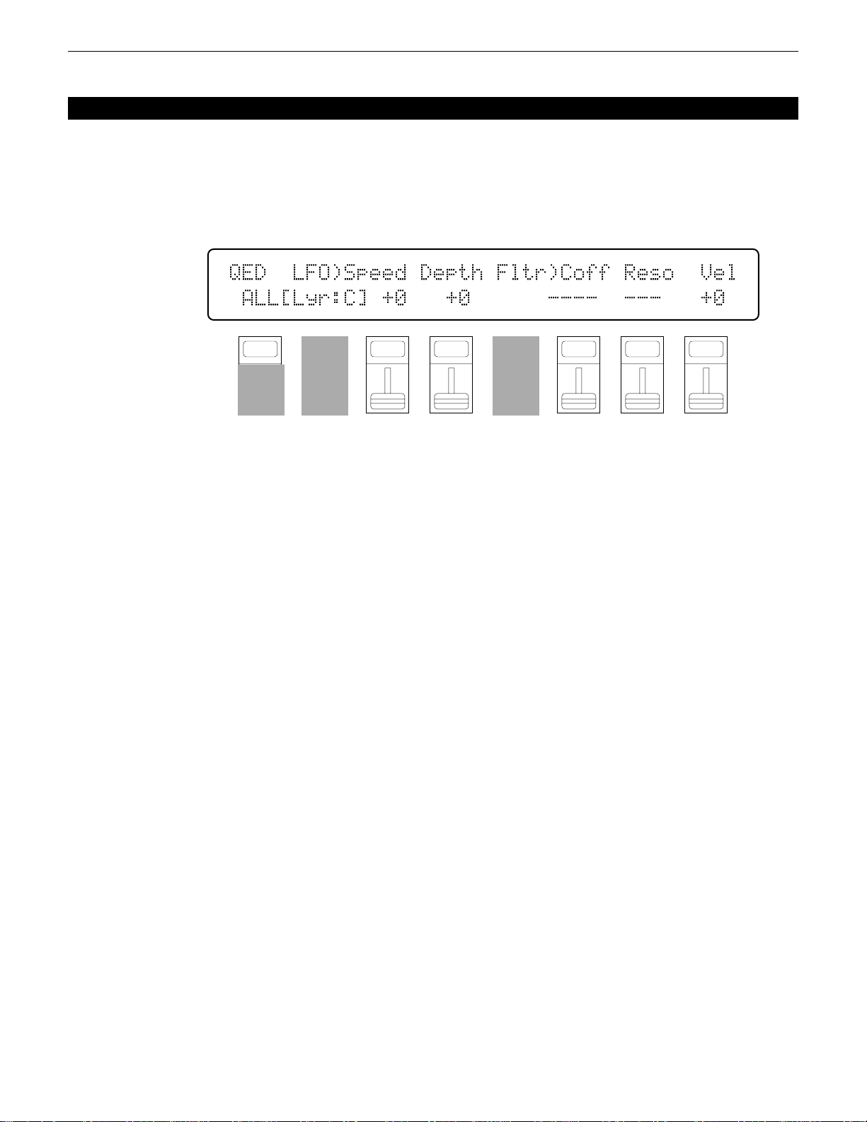
2: LFO & FILTER OFFSET
[PERFORMANCE] → [QUICK EDIT] → [MENU] → 2:LFO,Filter Offset → [ENTER/YES]
These parameters allow the main LFO and filter parameters of the voices assigned
to each layer to be modified to some degree. The actual LFO and filter parameters of
the voices are not affected, these “offset” values are only effective in the performance
mode.
QED``LFO)Speed`Depth`Fltr)Coff`Reso``Vel
`ALL[Lyr:C]`+0```+0``````----``---```+0
F1
CS1
F2
CS2
F3
CS3
Use PROGRAM keys [1] through [4] (LAYER SELECT A, B, C, and D) to
select the layer to be edited.
Hold the [F1] function key (“ALL”) while editing any of the following
parameters to change its value by the same amount for all layers simultaneously.
Speed (LFO speed)
Range: -99 … +99
Controls: [CS3], [-1] [+1], Dial
Modifies the speed of the LFO (this corresponds to the “Speed” parameter
of the main voice LFO — see page 78). Plus (+) values increase the LFO
speed while minus (-) values reduce the speed.
No matter how much offset is applied, the minimum and maximum LFO
speeds cannot be exceeded.
F4
CS4
F5
CS5
F6
CS6
F7
CS7
F8
CS8
Depth (LFO depth)
Range: -99 … +99
Controls: [CS4], [-1] [+1], Dial
Modifies the amplitude, pitch, and frequency modulation depth of the LFO
(this corresponds to the “Pmod”, “Amod”, and “Fmod” parameters of the main
voice LFO — see page 78 and 79). Plus (+) values produce greater modulation
depth while minus (-) values reduce the modulation depth.
No matter how much offset is applied, the minimum and maximum LFO
depth values cannot be exceeded.
29PERFORMANCE EDIT MODE / QUICK EDIT
Page 31

Coff (Filter cutoff frequency)
Range: -127 … +127
Controls: [CS6], [-1] [+1], Dial
Modifies the filter cutoff frequency (this corresponds to the voice filter
“CutOff” parameter — see page 65). Plus (+) values increase the cutoff frequency while minus (-) values lower the cutoff frequency. This parameter
cannot be used if the filter is set to “Thru”. In this case “----” appears in place
of the parameter value.
No matter how much offset is applied, the minimum and maximum cutoff
frequency values cannot be exceeded.
Reso (Filter resonance)
Range: -99 … +99
Controls: [CS7], [-1] [+1], Dial
Modifies the height of the filter’s resonant peak (this corresponds to the
filter “Resonance” parameter — see page 68). Plus (+) values increase resonance while minus (-) values reduce resonance. This parameter cannot be used
if the filter is
rameter value.
No matter how much offset is applied, the minimum and maximum resonance values cannot be exceeded.
not set to “LPF”. In this case “---” appears in place of the pa-
Vel (Velocity sensitivity)
Range: -127 ... +127
Controls: [CS8], [-1] [+1], Dial
Modifies the filter velocity sensitivity setting (see page 72). Plus “+” settings increase sensitivity while minus “-” settings reduce sensitivity.
No matter how much offset is applied, the minimum and maximum velocity
values cannot be exceeded.
30 PERFORMANCE EDIT MODE / QUICK EDIT
Page 32

3: CONTROLLER CONDITIONS
[PERFORMANCE] → [QUICK EDIT] → [MENU] → 3:Controller Condition → [ENTER/YES]
These parameters determine how the performance layers are affected by keyboard
aftertouch response, the modulation wheel, and the foot controller.
QED`CTRL)Use`AT``MW```FC`````AT>MW`MW>AT
`ALL[Lyr:A]LyrA`LyrA`LyrA``````off``off
F1
CS1
F2
CS2
Use PROGRAM keys [1] through [4] (LAYER SELECT A, B, C, and D) to
select the layer to be edited.
Hold the [F1] function key (“ALL”) while editing any of the following
parameters to change its value by the same amount for all layers simultaneously.
AT (Aftertouch)
Range: off, LyrA, LyrB, LyrC, LyrD
Controls: [CS3], [-1] [+1], Dial
The aftertouch control settings from the voice assigned to the selected layer
(LyrA, LyrB, LyrC, or LyrD) are applied to the layer being edited (i.e. the
layer selected via PROGRAM keys [1] through [4]). Select “off” to turn
aftertouch control off for the layer being edited.
F3
CS3
F4
CS4
F5
CS5
F6
CS6
F7
CS7
F8
CS8
MW (Modulation wheel)
Range: off, LyrA, LyrB, LyrC, LyrD
Controls: [CS4], [-1] [+1], Dial
The modulation wheel control settings from the voice assigned to the selected layer (LyrA, LyrB, LyrC, or LyrD) are applied to the layer being edited
(i.e. the layer selected via PROGRAM keys [1] through [4]). Select “off” to
turn modulation wheel control off for the layer being edited.
FC (Foot controller)
Range: off, LyrA, LyrB, LyrC, LyrD
Controls: [CS6], [-1] [+1], Dial
The foot controller control settings from the voice assigned to the selected
layer (LyrA, LyrB, LyrC, or LyrD) are applied to the layer being edited (i.e.
the layer selected via PROGRAM keys [1] through [4]). Select “off” to turn
foot control off for the layer being edited.
31PERFORMANCE EDIT MODE / QUICK EDIT
Page 33

AT>MW (Aftertouch ➔ modulation wheel)
Range: off, on
Controls: [CS7], [-1] [+1], Dial
When this parameter is turned “on,” aftertouch can be used to prouce the
same effect as the modulation wheel, in addition to any parameters assigned to
aftertouch.
MW>AT (Modulation wheel ➔ aftertouch)
Range: off, on
Controls: [CS8], [-1] [+1], Dial
When this parameter is turned “on,” the modulation wheel can be used to
produce the same effect as aftertouch, in addition to any parameters assigned to
the modulation wheel.
32 PERFORMANCE EDIT MODE / QUICK EDIT
Page 34

4: OTHER CONDITIONS
[PERFORMANCE] → [QUICK EDIT] → [MENU] → 4:Other Condition → [ENTER/YES]
Other parameters that can be individually set for each performance layer are
provided in this screen: sustain enable, pitch envelope generator enable, oscillator
fixed note mode and note number.
QED`OTHER)``Sustain``PEG``Fix`FixNote
`ALL[Lyr:A]``````on```on``off``---
F1
CS1
F2
CS2
F3
CS3
Use PROGRAM keys [1] through [4] (LAYER SELECT A, B, C, and D) to
select the layer to be edited.
Hold the [F1] function key (“ALL”) while editing any of the following
parameters to change its value by the same amount for all layers simultaneously.
Sustain
Range: off, on
Controls: [CS4], [-1] [+1], Dial
Turns sustain off or on for the selected layer. Interesting effects can be
produced by setting some layers to respond to the sustain footswitch in the
normal way, while others do not sustain at all.
PEG (Pitch EG enable)
Range: off, on
Controls: [CS5], [-1] [+1], Dial
F4
CS4
F5
CS5
F6
CS6
F7
CS7
F8
CS8
Turns pitch envelope generator control of the selected layer off or on.
Fix (Oscillator fix)
Range: off, on
Controls: [CS6], [-1] [+1], Dial
Turns the oscillator fixed-pitch mode on or off (see page 58). The FixNote
parameter described below can be used to set the note produced when the “fix”
mode is turned on.
33PERFORMANCE EDIT MODE / QUICK EDIT
Page 35

FixNote (Oscillator fix note number)
Range: C-2 … G8
Controls: [CS7], [-1] [+1], Dial
Sets the frequency (note) at which the selected layer will be played when
the “fix” mode is turned on (“---” is displayed in place of the note when the
“fix” mode is turned off).
The C-2 to G8 range of this parameter covers a full 10-1/2 octaves. “C3”
corresponds to “middle C” on a keyboard.
34 PERFORMANCE EDIT MODE / QUICK EDIT
Page 36

5: EFFECT TYPE
[PERFORMANCE] → [QUICK EDIT] → [MENU] → 5:Effect Type → [ENTER/YES]
The SY85 features a complex, high-performance effect system that can be pro-
grammed easily via the parameters presented here and in the following screen.
For a complete list of effect parameters see page 274.
QED`EFFECT)```Type```````````Wet`Balance
``06:Rev.Stage1``57:EQ`->`Sym```50%``50%
F1
CS1
F2
CS2
Effect Type 1/2
Range: 0 … 90
Controls: [CS1]/[CS4], [-1] [+1], Dial
[CS1] selects any of the SY85’s 90 effect types for the EFFECT 1 processor, and [CS4] does the same for the EFFECT 2 processor. See page 254 for
more details on the SY85 effect system.
Wet Balance 1/2
Range: 0 … 100
Controls: [CS7]/[CS8], [-1] [+1], Dial
[CS7] controls the balance between the direct no-effect sound and the effect
sound of the EFFECT 1 processor, while [CS8] does the same for the EFFECT
2 processor. The higher the value the deeper the effect. See page 254 for more
details on the SY85 effect system.
F3
CS3
F4
CS4
F5
CS5
F6
CS6
F7
CS7
F8
CS8
35PERFORMANCE EDIT MODE / QUICK EDIT
Page 37

6: EFFECT PARAMETER
[PERFORMANCE] → [QUICK EDIT] → [MENU] → 6:Effect Param → [ENTER/YES]
QED`EF`PARAM)`<`1:Stge>``)Rev.Time``[s](
`2.5``1.0```45`12.0```+0```+0``0.8``100
F1
CS1
F2
CS2
F3
CS3
F4
CS4
F5
CS5
F6
CS6
F7
CS7
F8
CS8
This screen provides access to the four main parameters each for the current
selected effect 1 and effect 2. The four effect 1 parameters are edited via [CS1]
through [CS4], while the four effect 2 parameters are edited via [CS5] through [CS8].
The parameters are different for each effect (refer to page 274 for details). The
EFFECT mode PARAMETERS screen described on page 44 provides full access to
all 8 effect parameters.
36 PERFORMANCE EDIT MODE / QUICK EDIT
Page 38

1: MODE, TYPE
[PERFORMANCE] → [EFFECT EDIT] → [MENU] → 1:Mode, Type → [ENTER/YES]
The SY85 features a dual-processor effect system that includes 90 top-quality
digital effects. Two different effects can be connected in series or parallel, providing
an extensive range of possible configurations.
EF`Mode`````EF1`Type```````EF2`Type``
```2:para```06:Rev.Stage1``57:EQ`->`Sym
F1
CS1
Mode
Range: 0:off, 1:seri, 2:para
Controls: [CS1], [-1] [+1], Dial
Determines whether the SY85’s two effect processors are connected in
series (“1:seri”) or in parallel (“2:para”), or whether the entire effect system is
turned off (“0:off”).
EF1 Type
Range: 0 … 90
Controls: [CS3], [-1] [+1], Dial
Selects any of the SY85’s 90 effect types for the EFFECT 1 processor. See
page 254 for more details on the SY85 effect system, and page 274 for a
complete list of the available effects.
F2
CS2
F3
CS3
F4
CS4
F5
CS5
F6
CS6
F7
CS7
F8
CS8
EF2 Type
Range: 0 … 90
Controls: [CS6], [-1] [+1], Dial
Selects any of the SY85’s 90 effect types for the EFFECT 2 processor. See
page 254 for more details on the SY85 effect system, and page 274 for a
complete list of the available effects.
37PERFORMANCE EDIT MODE / EFFECT EDIT
Page 39

2: SEND SELECT & LEVEL
[PERFORMANCE] → [EFFECT EDIT] → [MENU] → 2:Send → [ENTER/YES]
The parameters provided here determine to which of the SY85 effect stages the
output from the voice assigned to each layer is sent, and at what level. It is also
possible to control the effect send level via keyboard dynamics and key scaling.
EF`Send`<InitVce`>`Switch`Levl`VelS`Kscl
``Layer=A(¡A1)```1a/-`2a/b`127```+0```+0
F1
CS1
F2
CS2
F3
CS3
Layer
Range: A, B, C, D
Controls: [CS2], PROGRAM [1] … [4], [-1] [+1], Dial
Selects the layer to be edited. The name of the voice assigned to the se-
lected layer is shown between parentheses on the upper line of the display.
Switch 1a, 1b/2a, 2b
Range: See text below.
Controls: [CS4]/[CS5], [-1] [+1], Dial
Determines to which of the EFFECT 1 and EFFECT 2 effect stages the
output from the current layer is sent. The [-1] and [+1] keys can then be used
to turn the stage on (“a” or “b”) or off (“.”). The [CS4] and [CS5] sliders
select the following settings in sequence:
F4
CS4
F5
CS5
F6
CS6
F7
CS7
F8
CS8
CS4 (EFFECT 1) CS5 (EFFECT 2)
1./. (a and b off) 2./. (a and b off)
1a/. (a on, b off) 2a/. (a on, b off)
1a/b (a and b on) 2a/b (a and b on)
1./b (a off, b on) 2./b (a off, b on)
If a “single” type effect is selected then only stage “a” can be selected. If a
“dual” or “cascade” type effect is selected, then both stages “a” and “b” can be
selected. An effect stage that cannot be selected is represented by “-” on the
display.
38 PERFORMANCE EDIT MODE / EFFECT EDIT
Page 40

Send (Send level)
Range: 0 … 127
Controls: [CS6], [-1] [+1], Dial
This parameter adjusts the amount of direct voice signal that is sent to the
effect processors, determining the strength of the final effect sound. A setting
of “0” results in no effect, leaving only the “dry” sound of the voice. The
maximum setting of “127” produces the maximum amount of effect.
VelS (Send velocity sensitivity)
Range: -7 … +7
Controls: [CS7], [-1] [+1], Dial
Determines how the send level from the selected layer is affected by velocity changes (e.g. keyboard dynamics).
Plus “+” settings produce higher send levels in response to higher velocity
values — i.e. the harder a key is played, the higher the send level, and therefore the deeper the effect. The maximum setting of “+7” produces the maximum level variation in response to velocity changes. Minus “-” settings produce
the opposite effect: lower send level in response to higher velocity. A setting of
“+0” results in no send level variation.
Kscl (Send key scaling)
Range: -7 … +7
Controls: [CS8], [-1] [+1], Dial
Allows the send level for the selected layer to be varied across the entire
pitch range (i.e. keyboard range).
Plus (“+”) settings produce a higher send level for the low notes and a
lower send level for the high notes. The maximum “+7” setting produces the
greatest send level variation across the pitch range. Minus (“-”) settings produce the opposite effect — a lower low-note send level and higher high-note
send level. A setting of “+0” results in no send level variation.
39PERFORMANCE EDIT MODE / EFFECT EDIT
Page 41

3: LAYER DRY OUTPUT SELECT
[PERFORMANCE] → [EFFECT EDIT] → [MENU] → 3:Layer Dry Out Select → [ENTER/YES]
These parameters determine turn the “dry lines” (i.e. the signal paths which bypasses each effect processor) on or off, determining whether any dry signal output
can occur at OUTPUT 1 and OUTPUT 2.
OUTPUT`Select`<InitVce`>`Dry1`Dry2`
``Layer=A(¡A1)`````````````on```on
Layer
Range: A, B, C, D
Controls: [CS2], PROGRAM [1] … [4], [-1] [+1], Dial
lected layer is shown between parentheses on the upper line of the display.
Dry1
Range: off, on
Controls: [CS6], [-1] [+1], Dial
When this parameter is turned “off,” the “WET:DRY BALANCE” parameters
(page 42) have no effect.
Dry2
Range: off, on
Controls: [CS7], [-1] [+1], Dial
F1
CS1
F2
CS2
F3
CS3
F4
CS4
F5
CS5
F6
CS6
F7
CS7
F8
CS8
Selects the layer to be edited. The name of the voice assigned to the se-
Turns the “dry line” bypassing the EFFECT 1 signal processor on or off.
40
Turns the “dry line” bypassing the EFFECT 2 signal processor on or off.
When this parameter is turned “off,” the “WET:DRY BALANCE” parameters
(page 42) have no effect.
PERFORMANCE EDIT MODE / EFFECT EDIT
Page 42

4: OUTPUT LEVEL
[PERFORMANCE] → [EFFECT EDIT] → [MENU] → 4:Output Level → [ENTER/YES]
Depending on the selected effects the SY85 effect system can have up to four
separate output levels that are adjusted by the parameters provided in this screen.
EF`OutLevel`1a```1b`````````````2a```2b`
`EF1(sngl)=100%``--`EF2(casc)=``--``100%
F1
CS1
F2
CS2
F3
CS3
F4
CS4
F5
CS5
F6
CS6
1a, 1b, 2a, and 2b (Effect output levels)
Range: 0 … 100
Controls: [CS3], [CS4], [CS7], [CS8], [-1] [+1], Dial
The [CS3] and [CS4] sliders adjust the output levels of the effect 1 “1a”
and “1b” stages, respectively, while the [CS7] and [CS8] sliders adjust the
output levels of the effect 2 “2a” and “2b” stages. A setting of “0” turns output
from the corresponding effect stage off, while a setting of “100” produces
maximum output level.
If the selected effect is a “single” type, then only the “1a” or “2a” output
level is available. If it is a “cascade” type, then only the “1b” or “2b” output
level is available. Both the “1a” and “1b” or “2a” and “2b” levels are available
only if the selected effect is a “dual” type. The type of the effects currently
selected for the effect 1 and effect 2 processors are shown in parentheses on
the bottom line of the display. See page 254 for details on the effect stages and
the SY85 effect system in general.
If a controller is assigned to any of the output level parameters (page 45),
an inverse “c” will appear to the right of the parameter.
F7
CS7
F8
CS8
41PERFORMANCE EDIT MODE / EFFECT EDIT
Page 43

5: WET:DRY BALANCE
[PERFORMANCE] → [EFFECT EDIT] → [MENU] → 5:Wet:Dry Balance → [ENTER/YES]
The balance between the direct sound of the voice and the effect sound is a
delicate thing. Even slight changes can make a big difference to the final sound. The
parameters provided in this screen provide precise balance control.
EF`Wet:Dry`Balance`````
`````Out1=``50`:`50``````Out2=``50`:`50
F1
CS1
F2
CS2
F3
CS3
Out1 Wet/Out2 Wet
Range: 0 … 100
Controls: [CS3]/[CS7], [-1] [+1], Dial
These parameters and the corresponding “Out1 Dry” and “Out2 Dry” parameters, below, work together to balance the effect (“wet”) and direct (“dry”)
signals delivered via the EFFECT 1 and EFFECT2 processors. Higher “Wet”
values produce more effect sound in relation to the direct, dry sound of the
voice.
Although the “Wet” and “Dry” parameters can be set independently, adjusting one will cause the other to change so that their total is always 100(%).
If a controller is assigned to the “Out1 Wet” or “Out2 Wet” parameter
(page 45), an inverse “c” will appear to the right of the parameter.
Out1 Dry/Out2 Dry
Range: 0 … 100
Controls: [CS4]/[CS8], [-1] [+1], Dial
F4
CS4
F5
CS5
F6
CS6
F7
CS7
F8
CS8
These parameters and the corresponding “Out1 Wet” and “Out2 Wet” parameters, above, work together to balance the effect (“wet”) and direct (“dry”)
signals delivered via the EFFECT 1 and EFFECT 2 processors, respectively.
Higher “Dry” values produce more direct, dry sound in relation to the effect
sound.
Although the “Wet” and “Dry” parameters can be set independently, adjusting one will cause the other to change so that their total is always 100(%).
If a controller is assigned to the “Out1 Dry” or “Out2 Dry” parameter (page
45), an inverse “c” will appear to the right of the parameter.
42 PERFORMANCE EDIT MODE / EFFECT EDIT
Page 44

6: SEND & EFFECT 2 MIX LEVEL
[PERFORMANCE] → [EFFECT EDIT] → [MENU] → 6:Mix Level → [ENTER/YES]
These parameters determine the mix level between each effect send and the output
of the preceding effect stage. Refer to the section beginning on page 254 for details
on the overall SY85 effect system.
EF`Mix`Level```EF2``Insert`1b```2a```2b`
````````````````--`````````--```--````0%
F1
CS1
F2
CS2
F3
CS3
F4
CS4
EF2 Mix (Effect 2 mix level)
Range: 0 … 100
Controls: [CS4], [-1] [+1], Dial
Mixes the output of the EFFECT 2 processor with that of the EFFECT 1
processor. This parameter can only be used with the “serial” effect mode is
selected. If any other mode is selected (“off” or “para”), “---” appears on the
display in place of the value.
If a controller is assigned to the EF2 Mix parameter (page 45), an inverse
“c” will appear to the right of the parameter.
Insert 1b, 2a, 2b (Insert level)
Range: 0 … 100
Controls: [CS6], [CS7], [CS8], [-1] [+1], Dial
These parameters mix the dry signal sent to the corresponding effect stage
with the output of the preceding effect stage. The higher the value the greater
mix level. If the current effect configuration does not allow one of these mix
parameters, “--” will appear in place of the mix level parameter.
If a controller is assigned to the one of these parameters (page 45), an
inverse “c” will appear to the right of the parameter.
F5
CS5
F6
CS6
F7
CS7
F8
CS8
43PERFORMANCE EDIT MODE / EFFECT EDIT
Page 45

7: EFFECT 1 PARAMETERS
8: EFFECT 2 PARAMETERS
[PERFORMANCE] → [EFFECT EDIT] → [MENU] → 7:EF1 Parameter → [ENTER/YES]
→ 8:EF2 Parameter → [ENTER/YES]
Each of the SY85’s 90 effects has 8 parameters that can be edited via the param-
eters in this screen to fine-tune the effect.
EF1`PARAM`<Rev.Stage1>```)ER/Rev`Bal[%](
`2.5``1.0```10```32```16````4````0`12.0
F1
CS1
F2
CS2
F3
CS3
F4
CS4
F5
CS5
F6
CS6
F7
CS7
F8
CS8
Each parameter is controlled by the corresponding slider (i.e. the slider
immediately below each parameter). The [-1]/[+1] keys and data entry dial can
also be used to edit the parameter at which the cursor is currently located.
Refer to page 274 for a complete listing of the parameters provided for
each effect.
44 PERFORMANCE EDIT MODE / EFFECT EDIT
Page 46

9: CONTROL PARAMETERS
[PERFORMANCE] → [EFFECT EDIT] → [MENU] → 9:Control Parameter → [ENTER/YES]
The SY85 [CS1] and [CS2] sliders can be assigned to control different effect
parameters in real time while playing in the voice or performance modes. The parameters provided in this screen determine which effect parameters are to be controlled
by the [CS1] and [CS2] sliders, the minimum and maximum parameter values, and
assign MIDI control numbers to the same parameters for MIDI effect control.
EF`CTRL)````````(`Min``Max``Additional`
``CS1`:`off````````0%`100%`000:off
F1
CS1
F2
CS2
F3
CS3
F4
CS4
CS1/CS2 (CS1/CS2 switch)
Range: CS1, CS2
Controls: [CS1], [-1] [+1], Dial
Selects [CS1] or [CS2] for assignment.
Parameter (Effect parameter)
Range: Depends on selected effects.
Controls: [CS2], [-1] [+1], Dial
Selects the effect parameter to be controlled by the currently selected slider.
Since each effect has as many as 8 different parameters, the maximum number
of settings available for this parameter will be 8: “Ef1prm1” through “Ef1prm8”
on the display, for example, stands for “effect 1 parameter 1” through “effect 1
parameter 8”. The parameters available for each effect are different, but the
name of the selected parameter will be shown between the parentheses on the
top line of the display. Parameters that can not be assigned to the sliders are
indicated by dashes (“--------”) instead of a parameter name.
F5
CS5
F6
CS6
F7
CS7
F8
CS8
Min (Minimum parameter value)
Range: 0 … 100
Controls: [CS4], [-1] [+1], Dial
Sets the lower limit of the [CS1] or [CS2] control range. A setting of “0”,
for example, means that when the slider is set to its lowest position the assigned parameter will also be set to its lowest value. A setting of “50” means
that the lowest slider position will set the assigned parameter to about 50% of
its range (a parameter with a range of 0 to 127, for example, would be set to
about 63).
If a controller is assigned to the “Min” parameter, an inverse “c” will
appear to the right of the parameter.
45PERFORMANCE EDIT MODE / EFFECT EDIT
Page 47

Max (Maximum parameter value)
Range: 0 … 100
Controls: [CS5], [-1] [+1], Dial
Sets the upper limit of the [CS1] or [CS2] control range. A setting of
“100”, for example, means that when the slider is set to its highest position the
assigned parameter will also be set to its highest value. A setting of “80”
means that the highest slider position will set the assigned parameter to about
80% of its range (a parameter with a range of 0 to 127, for example, would be
set to about 102).
If a controller is assigned to the “Max” parameter, an inverse “c” will
appear to the right of the parameter.
Additional (Additional MIDI control)
Range: 000 … 120, AfterTch, Velocity, KeyScale, LFO
Controls: [CS6], [-1] [+1], Dial
This parameter allows MIDI control change numbers to be assigned to the
selected effect parameters, so that they can be controlled from the SY85 controllers (modulation wheel, foot controller, etc) or an external MIDI device that
is capable of transmitting control change messages. Additional settings include
“AfterTch” for keyboard aftertouch control, “Velocity” for keyboard velocity
control, “KeyScale” for key scaling control, and “LFO” for internal LFO control. This is in addition to control via the [CS1] and [CS2] sliders. MIDI control change numbers 000 through 120 can be assigned. Some control change
numbers are already defined, while others are not assigned to any specific
controller (see chart below).
MIDI CONTROL CHANGE NUMBER/DEVICE
0: “--------”
1: “Mod.Whl.”
2: “Breath C”
4: “Foot Cnt”
5: “Porta.Tm”
6: “Data Ent”
7: “Main Vol”
8: “Balance ”
10: “Panpot ”
11: “Express.”
64: “Hold 1 ”
65: “Porta.Sw”
66: “Sostenut”
67: “Soft ”
69: “Hold 2 ”
46 PERFORMANCE EDIT MODE / EFFECT EDIT
91: “Effect D”
92: “TremoloD”
93: “Chorus D”
94: “CelesteD”
95: “Phaser D”
96: “Inc. ”
97: “Dec. ”
98: “NRPN LSB”
99: “NRPN MSB”
100: “RPN LSB”
101: “RPN MSB”
121: “AfterTch”
122: “Velocity”
123: “KeyScale”
124: “LFO ”
Page 48

10: CONTROL LFO
[PERFORMANCE] → [EFFECT EDIT] → [MENU] → 10:Control LFO → [ENTER/YES]
All of the modulation-type effects — chorus, flanging, etc. — require LFO control. The SY85 has an independent effect LFO that is set up by the following parameters.
EF`CTRL`LFO``Waveform````Speed````Delay`
``````````````∆˚∆`tri````````0````````0
F1
CS1
F2
CS2
F3
CS3
Wave (LFO waveform)
Range: tri, dwn, up, squ, sin, S/H, 1tm
Controls: [CS4], [-1] [+1], Dial
Determines the waveform of the effect LFO.
“tri” = Triangle. “dwn” = Downward sawtooth.
“up” = Upward sawtooth. “squ” = Square.
“sin” = Sine. “S/H” = Sample and hold.
If a controller is assigned to the “Wave” parameter (page 45), an inverse
“c” will appear to the right of the parameter.
Speed (LFO speed)
Range: 0 … 99
Controls: [CS6], [-1] [+1], Dial
F4
CS4
F5
CS5
“1tm” = Upward 1-shot.
F6
CS6
F7
CS7
F8
CS8
0 Hertz. The fastest setting of 99 produces an LFO speed of approximately 25
Hertz.
“c” will appear to the right of the parameter.
Delay
Range: 0 … 99
Controls: [CS8], [-1] [+1], Dial
effect LFO operation for the selected element.
“99” produces a delay of approximately 2.66 seconds before the effect LFO
begins operation.
“c” will appear to the right of the parameter.
Sets the speed of the effect LFO.
“0” is the slowest speed setting, producing an LFO speed of approximately
If a controller is assigned to the “Speed” parameter (page 45), an inverse
Sets the delay time between the beginning of a note and the beginning of
The minimum setting “0” results in no delay, while the maximum setting of
If a controller is assigned to the “Delay” parameter (page 45), an inverse
47PERFORMANCE EDIT MODE / EFFECT EDIT
Page 49

EFFECT DATA COPY
[PERFORMANCE] → [EFFECT EDIT] → [COPY]
This function facilitates performance effect editing by allowing the effect parameters from any other song, voice, or performance combination to be copied to the
current performance combination. You can copy an effect setup that is close to the
type you want, then edit it to produce the required sound.
EFFECT`COPY`````From
````````````````PFM``¡A1:InitPerf```````
From
Range: Any song, voice or performance combination
Controls: MEMORY, GROUP, PROGRAM, [CS5], [-1] [+1], Dial
select the memory area from which the source voice is to be selected. Use the
GROUP keys to select the source voice bank, then use the PROGRAM keys to
select the source voice number. The [CS5] slider and other data entry controls
can also be used to select the source voice number.
you sure?” will appear on the display.
F1
CS1
F2
CS2
F3
CS3
F4
CS4
F5
CS5
F6
CS6
F7
CS7
F8
CS8
Use the [INTERNAL 1], [INTERNAL 2], and [CARD] MEMORY keys to
Once the source voice has been selected, press the [ENTER/YES] key. “Are
EFFECT`COPY`````From
Are`you`sure`?``PFM``¡A1:InitPerf
Press the [ENTER/YES] key again to copy the effect data, or press [EXIT/
NO] to cancel the copy operation. Once the copy operation has finished, “Completed!” will appear on the display briefly, then the display will return to the
effect edit mode.
48 PERFORMANCE EDIT MODE / EFFECT EDIT
Page 50

EFFECT SIGNAL FLOW DISPLAY
[PERFORMANCE] → [EFFECT EDIT] → [SHIFT] + [F1] ~ [F3]
This function provides a graphic indication of the current effect system configura-
tion while in the effect edit mode.
● Overall Effect Flow
EFFECT`FLOW`Ú`∏Á
∏∏∏∏∏∏
Î`Ú`EF1=Rev.Stage1
`Mode=`para`Ú`ШШШШШЛФБ `Ú`EF2=EQ`->`Sym
F1
CS1
● Effect 1 Configuration
F2
CS2
F3
CS3
F4
CS4
F5
CS5
F6
CS6
F7
CS7
EF1`Send1a>---[Stge˜]------------◊->OUT1
`````````````````````````````````’-<DRY1
F1
CS1
F2
CS2
F3
CS3
F4
CS4
F5
CS5
F6
CS6
F7
CS7
F8
CS8
F8
CS8
● Effect 2 Configuration
EF2`Send2a>---[EQ```]-Ÿ-[Sym`˜]--◊->OUT2
````Send2b>-----------Û``````````’-<DRY2
F1
CS1
Press [SHIFT] + [F1] to see the overall effect system signal flow. Press [SHIFT]
+ [F2] to see the effect 1 section configuration, and [SHIFT] + [F3] for the effect 2
section configuration.
Refer the to section beginning on page 254 for details on the effect system.
F2
CS2
F3
CS3
F4
CS4
F5
CS5
F6
CS6
F7
CS7
F8
CS8
49PERFORMANCE EDIT MODE / EFFECT EDIT
Page 51

1: LAYER CONTROLLER SYNC
[PERFORMANCE] → [JOB] → [MENU] → 1:Layer Controller Sync → [ENTER/YES]
This function changes the controller parameters of all voices in the selected
perfomance combination to match those of the voice assigned to the specified
“source” layer.
PERFORMANCE`JOB`Layer`Controller`Sync```
``````````````````````````Source`LayerA
F1
CS1
F2
CS2
F3
CS3
F4
CS4
F5
CS5
F6
CS6
F7
CS7
F8
CS8
Use the [CS8] slider to select the source layer (A, B, C, or D) from which
the controller data is to be copied, then press [ENTER/YES] to begin the layer
controller sync procedure. The following confirmation display will appear:
PERFORMANCE`JOB`Layer`Controller`Sync
Are`you`sure`?````````````Source`LayerA
Press [ENTER/YES] again to confirm that you want to go ahead with the
operation (which will overwrite all controller data for the voices assigned to all
layers other than the source layer), or press [EXIT/NO] to cancel.
When the data has been copied, “Completed!” will appear briefly on the
display, then the display will return to the mode that was engaged prior to
calling the layer controller sync function.
50 PERFORMANCE EDIT MODE / JOB
Page 52

2: LAYER EXCHANGE
[PERFORMANCE] → [JOB] → [MENU] → 2:Layer Exchange → [ENTER/YES]
This function can be used to eliminate the audible effects of slight note delays
that can occur in the performance play mode. The notes played by layers A, B, C,
and D are sounded in sequence in the performance play mode. Normally the delay is
so slight that it is not audible. If a voice with a sharp attack is assigned to one of the
later layers (C or D), however, the delay can “soften” the attack of the voice. The
problem can be overcome by using this function to exchange layers A and D, for
example, so that the voice with the strong attack is assigned to layer A instead of
layer D. Since layer A is sounded first, the sharpness of the attack will be retained.
PERFORMANCE`JOB`Layer`Exchange
`````````````````````````````````A`†¥`A
F1
CS1
F2
CS2
F3
CS3
F4
CS4
F5
CS5
F6
CS6
F7
CS7
F8
CS8
Use the [CS7] and [CS8] sliders to select the layers to be exchanged (A
through D), then press [ENTER/YES] to begin the layer exchange procedure.
The following confirmation display will appear:
PERFORMANCE`JOB`Layer`Exchange
Are`you`sure`?```````````````````A`†¥`A
Press [ENTER/YES] again to confirm that you want to go ahead with the
layer exchange operation, or press [EXIT/NO] to cancel.
When the data has been exchanged, “Completed!” will appear briefly on the
display, then the display will return to the mode that was engaged prior to
calling the layer exchange function.
51PERFORMANCE EDIT MODE / JOB
Page 53

3: PERFORMANCE EDIT RECALL
[PERFORMANCE] → [JOB] → [MENU] → 3:Recall → [ENTER/YES]
If you’re dissatisfied with the results of edits you’ve made to a performance
combination, or have accidentally lost track of changes made, use the PERFORMANCE EDIT RECALL function to recall the pre-edit performance data from the
SY85’s backup buffer memory.
PERFORMANCE`JOB`Recall````````<InitPerf>
``
F1
CS1
F2
CS2
F3
CS3
F4
CS4
F5
CS5
F6
CS6
F7
CS7
F8
CS8
Press [ENTER/YES] to begin the recall procedure. The following confirma-
tion display will appear:
PERFORMANCE`JOB`Recall````````<InitPerf>
Are`you`sure`?
Press [ENTER/YES] again to confirm that you want to go ahead with the
recall operation (which will erase all current edited data), or press [EXIT/NO]
to cancel.
When the original voice data has been recalled, “Completed!” will appear
briefly on the display, then the display will return to the mode that was engaged prior to calling the performance edit recall function.
52 PERFORMANCE EDIT MODE / JOB
Page 54

4: PERFORMANCE INITIALIZE
[PERFORMANCE] → [JOB] → [MENU] → 4:Initialize → [ENTER/YES]
When you want to program a totally new performance combination “from
scratch,” rather than editing an existing combination, use this function to initialize all
performance parameters.
PERFORMANCE`JOB`Initialize``
`````````````````````````[EDIT]`LYR
F1
CS1
F2
CS2
F3
CS3
F4
CS4
F5
CS5
F6
CS6
F7
CS7
F8
CS8
Press [F6] if you want to initialize the entire performance combination
currently in the edit buffer, or [F7] if you only want to initialize one specific
layer. If you choose [F7], use the [CS8] slider to select the layer you want to
initialize.
Press [ENTER/YES] to begin the initialize procedure. The following confirmation display will appear:
PERFORMANCE`JOB`Initialize
Are`you`sure`?```````````[EDIT]`LYR
Press [ENTER/YES] again to confirm that you want to go ahead with the
initialize operation (which will erase all current edited data), or press [EXIT/
NO] to cancel.
When the performance data has been initialized, “Completed!” will appear
briefly on the display, then the display will return to the mode that was engaged prior to calling the performance initialize function.
53PERFORMANCE EDIT MODE / JOB
Page 55

[SHIFT] + [STORE]
The illustrations here are not available.
performance combination being edited with the same performance combination prior
to editing.
[STORE] key while holding the [SHIFT] key. The [PERFORMANCE] LED will
flash, indicating that the compare mode is engaged. Although you can select different
edit mode display screens, data cannot be edited in the compare mode. Press [EXIT/
NO] to return to the edit mode and the performance combination being edited.
PERFORMANCE COMPARE
The performance compare function makes it possible to compare the sound of a
To temporarily recall the original performance data while editing, press the
54 PERFORMANCE EDIT MODE / COMPARE
Page 56

[STORE]
PERFORMANCE STORE
When you’re satsfied with a new performance combination you’ve created in the
performance edit mode, use the store function described below to store the new
performance combination to an internal or card memory location.
PERFORMANCE`STORE`````Layer-:<-------->
``To``¡A1:InitPerf```¡A1u`¡A1u`¡A1u`¡A1u
F1
CS1
F2
CS2
F3
CS3
F4
CS4
F5
CS5
F6
CS6
F7
CS7
F8
CS8
When you’ve finished editing, return to the normal performance play mode
(press the [PERFORMANCE] key), and before selecting a different mode or
performance combination press the [STORE] key. You can now use the
MEMORY, GROUP, and NUMBER keys (or the [CS2] slider) to select the
memory location to which your new performance combination is to be stored.
Since any changes you have made via the LAYER VOICE EDIT MENU
(page 26) will be stored as voice data, it is also possible to specify the voice
memory loactions to which the voice data from each layer will be stored. The
[F5], [F6], [F7], and [F8] function keys select the layer A, B, C, and D layer
voices, respectively. The corresponding layer and voice name appears on the
upper display line. With the cursor in the appropriate position you can use the
MEMORY, GROUP, and NUMBER keys (or the corresponding slider) to select
the memory location to which each voice is to be stored. A “u” appearing next
to one of these voice numbers means that the voice is currently used by another performance combination, and therefore any changes to that voice will
affect the performance combination in which it is used. For more information
press the [SHIFT] key for a list of names of other performance combinations
that use the voices assigned to each layer.
Once the store location has been specified, press [ENTER/YES] to begin
the store procedure. The following confirmation display will appear:
PERFORMANCE`STORE`````````Are`you`sure`?
``To``¡A1:InitPerf```¡A1u`¡A1u`¡A1u`¡A1u
Press [ENTER/YES] again to confirm that you want to go ahead with the
store operation (which will erase all previous data in the specified memory
location), or press [EXIT/NO] to cancel.
When the performance data has been stored, “Completed!” will appear
briefly on the display, then the display will return to the mode that was engaged prior to calling the store function.
PERFORMANCE EDIT MODE / STORE
55
Page 57

Page 58

VOICE EDIT MODE
Page 59

OSCILLATOR
[VOICE] → [EDIT] → [MENU] → 1:Oscillator → [ENTER/YES]
This screen contains 6 parameters that determine the fundamental sound of the
voice being edited — including the number of the waveform on which the voice will
be based.
OSC``Wave``````Mode`Fine`Note`Rndm``Rvs`
P244`Sin```````norm```+0```+0````0``off`
Wave
Range: P001 … P244, I00 … I63, C00 … C63
Controls: [CS1], [-1] [+1], Dial
[INTERNAL 1], [INTERNAL 2], and [CARD] keys to select the memory area
from which the wave is to be selected. Please note that when SIMM memory is
wave memory installed, wave data can not be loaded into memory from a
waveform card. A complete listing of the internal waves is given in the Appendix, on page 310.
Mode
Range: fix, norm
Controls: [CS4], [-1] [+1], Dial
pitch) or fixed-pitch mode.
to be controllable from a keyboard or other type of controller, in which case
the “norm” mode should be selected. In some cases — sound effects in particular — you might want the same pitch to be produced no matter what note you
play on the keyboard or other controller. In this case, the “fix” mode is appropriate. The Note parameter described below can be used to set the note produced when the “fix” mode is selected.
F1
CS1
F2
CS2
F3
CS3
F4
CS4
F5
CS5
F6
CS6
F7
CS7
F8
CS8
Selects the wave (AWM waveform) to be used in the current voice. Use the
Determines whether the selected wave is reproduced in the normal (variable
Normally you want the pitch of the AWM wave (or waves) used in a voice
58
Fine
Range: -63 … 0 … +63
Controls: [CS5], [-1] [+1], Dial
Allows fine tuning of the selected AWM wave. Each increment corresponds
to approximately 1.17 cents (a “cent” is 1/100th of a semitone) so the lowest
setting (-63) shifts the pitch down by almost three quarters of a semitone, while
the highest setting (+63) shifts the pitch up by the same amount. A setting of
“+0” produces standard concert pitch (A3 = 440 Hertz).
VOICE EDIT MODE / 1:Oscillator
Page 60

Please note that this parameter is used to individually tune the current
voice. Overall tuning control is provided by the MASTER TUNE function
available in the UTILITY mode.
Note
Range: C-2 … G8, -64 … +63
Controls: [CS6], [-1] [+1], Dial
When the “fix” mode is selected this parameters sets the frequency (note) at
which the selected wave will be played. The C-2 to G8 range of this parameter
covers a full 10-1/2 octaves. “C3” corresponds to “middle C” on a keyboard.
When the “norm” mode is selected, this parameter is used to shift the
overall pitch of the entire keyboard up or down in semitone increments (i.e. a
“note shift” function). In this case the range of the parameters is from -64
through 0 to +63. A setting of “-12,” for example, shifts the pitch down by one
octave; a setting of “+4” shifts the pitch up by a major third.
Rndm (Random pitch)
Range: 0 … 7
Controls: [CS7], [-1] [+1], Dial
Sets the amount of random pitch variation produced each time a note is
played.
When this parameter is set to a value other than “0,” the pitch changes
randomly each time a note is played. The random pitch change is applied
independently to each note in a chord. A setting of “7” produces the greatest
amount of random pitch change.
This function is ideal for simulating the sound of instruments like the
clavichord, string sections or other ensembles in which the pitch of each note is
rarely in perfect tune with the others.
Rvs (Reverse)
Range: off, on
Controls: [CS8], [-1] [+1], Dial
When this parameter is turned “on,” the selected wave is played in reverse.
When Rvs is “on,” the pitch EG “Loop” parameter described on page 75 is
automatically turned “off.”
59VOICE EDIT MODE / 1:Oscillator
Page 61

1: AEG LEVEL & RATE
The illustrations here are not available.
[VOICE] → [EDIT] → [MENU] → 2:Amlitude EG → [ENTER/YES] → [ENTER/YES] →
→ [MENU] → 1:Level&Rate → [ENTER/YES]
The SY85’s main AEG (Amplitude Envelope generator) has five individually
programmable rates and two levels for exceptional envelope programming flexibility.
Next to the fundamental waveform used, the amplitude envelope is one of the most
important factors determining the overall sound of a voice.
AEG````R1```R2```L2```R3```L3```R4```RR`
`atk``π63`ƒ`63````0`π`63```63`ƒ``0`π`50
F1
CS1
Atk/Hld (Amplitude EG attack/hold mode)
Range: atk, hold
Controls: [CS1], [-1] [+1], Dial
The “Atk” and “Hld” mode settings affect the initial attack of the sound,
determining how the amplitude envelope begins. In the “Atk” mode, the envelope begins from zero level, reaching the maximum AWM level at a rate determined by the R1 (Rate 1) parameter. In this mode there will always be a slight
delay between the initiation of a note and maximum level.
R1 … RR, L2 … L3 (Rates & levels)
Range: 0 … 63
Controls: [CS2] … [CS8], [-1] [+1], Dial
F2
CS2
F3
CS3
F4
CS4
F5
CS5
F6
CS6
F7
CS7
π
F8
CS8
The following diagrams illustrate how the AEG rate and level parameters
determine the overall shape of the amplitude envelope.
● “Atk” Mode
60
VOICE EDIT MODE / 2:Amplitude EG
Page 62

The envelope begins at zero level, reaches maximum level at the rate deter-
The illustrations here are not available.
The illustrations here are not available.
mined by the R1 parameter, moves to L2 (Level 2) at R2 (Rate 2), moves on
to L3 (Level 3) at R3 (Rate 3), and finally decays to zero level at R4 (Rate 4)
if the note is held the entire time.
If the note is released before the end of the envelope described above, then
the sound decays to zero level from the point at which the note is released at
the rate determined by the RR (Release Rate) parameter.
● “Hld” Mode
If the “hold” mode is selected, the envelope begins immediately from maximum AWM level, allowing the fast attack transients of waveforms to pass
unaffected. In this case the R1 parameter is replaced by the HT (Hold Time)
parameter. The HT parameter determines the length of time between the beginning of the envelope and the point at which the envelope begins to move
towards L2 (Level 2) at R2 (Rate 2), as shown below.
For the level parameters, a setting of “0” corresponds to the lowest possible
level (no sound) while a setting of 63 produces the highest output level. A “0”
rate parameter setting produces the slowest rate between levels, while the
maximum setting of “63” produces the fastest (almost instantaneous) change.
VOICE EDIT MOD E / 2:Amplitude EG
61
Page 63

2: LEVEL SCALING
[VOICE] → [EDIT] → [MENU] → 2:Amlitude EG → [ENTER/YES] → [ENTER/YES] →
→ [MENU] → 2:Level Scaling → [ENTER/YES]
Level scaling produces natural level variations across the range of the keyboard
by allowing different level “offset” values to be applied to each of four “breakpoints”
set at appropriate keys.
LEVEL`SCALING`)POINT1`(`````````````````
``C1```G2```E4```F4```+0```+0```+0```+0
F1
CS1
F2
CS2
Point 1 … 4
Range: C-2 ... G8
Controls: [CS1] … [CS4], [-1] [+1], Dial, [SHIFT] + Keyboard
Allows four separate amplitude envelope generator level-scaling breakpoints
to be set at any notes between C-2 and G8 for the selected element.
To use the keyboard for breakpoint entry, simply select a breakpoint parameter by pressing the coresponding function key or moving the corresponding
continuous slider, then press the key at which you want to set the breakpoint
while holding the [SHIFT] key.
No breakpoint can be set to a key lower than the breakpoint to its left.
Offset 1 … 4
Range: -127 ... +127
Controls: [CS5] … [CS8], [-1] [+1], Dial
F3
CS3
F4
CS4
F5
CS5
F6
CS6
F7
CS7
F8
CS8
62
Sets the amount of level offset for each of the four level-scaling breakpoints set by the “Point” parameters described above.
Negative values reduce the level, and positive values increase the level at
the corresponding breakpoint. No matter what value is chosen, the EG level
will never exceed its minimum or maximum levels. When different offset
values are applied to adjacent breakpoints, the level varies smoothly between
the breakpoints.
VOICE EDIT MODE / 2:Amplitude EG
Page 64

3: SENSITIVITY
[VOICE] → [EDIT] → [MENU] → 2:Amlitude EG → [ENTER/YES] → [ENTER/YES] →
→ [MENU] → 3:Sensitivity → [ENTER/YES]
The parameters provided here determine how the amplitude envelope generator
responds to changes in keyboard velocity and range.
AMP```Vel```AtkRateVel`````RateScaling``
Sens.``+0````````-7`````````````+0``````
F1
CS1
F2
CS2
F3
CS3
F4
CS4
F5
CS5
F6
CS6
F7
CS7
Vel (Velocity sensitivity)
Range: -7 ... +7
Controls: [CS2], [-1] [+1], Dial
Determines how the output level of the current voice changes in response to
velocity changes (e.g. keyboard dynamics).
Plus “+” settings produce higher output level in response to higher velocity
values — i.e. the harder a key is played, the louder the sound. The maximum
setting of “+7” produces the maximum level variation in response to velocity
changes. Minus “-” settings produce the opposite effect: lower level in response
to higher velocity. A setting of “+0” results in no level variation.
AtkRateVel (Attack rate velocity sensitivity)
Range: -7 … +7
Controls: [CS4], [-1] [+1], Dial
Determines how key velocity (keyboard dynamics) affect the attack time of
the amplitude envelope generator.
Plus (“+”) settings produce an increase in attack time in proportion to key
velocity, while minus (“-”) settings produce a decrease in attack time in proportion to key velocity. The greater the value the greater the change in envelope
length.
F8
CS8
RateScaling
Range: -7 ... +7
Controls: [CS7], [-1] [+1], Dial
Allows the overall amplitude envelope generator decay rate for the selected
element to be varied across the entire pitch range.
Plus (“+”) settings produce a longer overall envelope time for the low notes
and a shorter envelope time for the high notes. This is useful for simulating
instruments such as piano, in which the low notes take much longer to decay
than the high notes. The maximum “+7” setting produces the greatest envelope
length variation across the pitch range. Minus (“-”) settings produce the opposite effect — short low notes and long high notes. A setting of “+0” results in
no envelope length variation.
VOICE EDIT MOD E / 2:Amplitude EG
63
Page 65

AEG DATA COPY
[VOICE] → [EDIT] → [MENU] → 2:Amplitude EG → [ENTER/YES] → [ENTER/YES] → [COPY]
This function facilitates voice editing by allowing the amplitude EG data from
any other voice (the “source” voice) to be copied to the current voice. You can copy
an envelope that is close to the type you want, then edit it to produce the required
sound.
AEG`COPY````````From`Voice``````````````
`````````````````````¡A1:InitVce
F1
CS1
From Voice
Range: Any INTERNAL or CARD voice
Controls: MEMORY, GROUP, PROGRAM, [CS5], [-1] [+1], Dial
Use the [INTERNAL 1], [INTERNAL 2], and [CARD] MEMORY keys to
select the memory area from which the source voice is to be selected. Use the
GROUP keys to select the source voice bank, then use the PROGRAM keys to
select the source voice number. The [CS5] slider and other data entry controls
can also be used to select the source voice bank and number.
Once the source voice has been selected, press the [ENTER/YES] key. “Are
you sure?” will appear on the display.
AEG`COPY````````From`Voice``````````````
Are`you`sure`?```````¡A1:InitVce
F2
CS2
F3
CS3
F4
CS4
F5
CS5
F6
CS6
F7
CS7
F8
CS8
64
Press the [ENTER/YES] key again to copy the AEG data, or press [EXIT/
NO] to cancel the copy operation. Once the copy operation has finished, “Completed!” will appear on the display briefly, then the display will return to the
amplitude EG edit mode.
VOICE EDIT MODE / 2:Amplitude EG
Page 66

1:TYPE, CUTOFF FREQUENCY
The illustrations here are not available.
[VOICE] → [EDIT] → [MENU] → 3:Filter → [ENTER/YES] → [ENTER/YES] →
→ [MENU] → 1:Cutoff Frequency → [ENTER/YES]
The SY85 features a sophisticated digital filter system that can be used to shape
the timbre of the voice being edited in a number of ways. Changes in the response
and cutoff frequency can be used to define the basic timbre of the voice, while EGcontrolled filter sweeps can produce a virtually unlimited range of time-based timbre
variations.
FILTER`Cutoff`Freq.`Type`Band`Reso`CTRL`
`````(------Hz)`---`THRU``---```--``LFO`
F1
CS1
F2
CS2
F3
CS3
F4
CS4
F5
CS5
Cutoff Freq. (Cutoff frequency)
Range: 0 … 127
Controls: [CS4], [-1] [+1], Dial
Sets the cutoff frequency of the selected filter.
Lower cutoff values produce a lower cutoff frequency and higher values
produce a higher cutoff frequency.
F6
CS6
F7
CS7
F8
CS8
With an LPF response (selected by the “Type” parameter, below), a lower
cutoff frequency reduces the range of high frequencies passed, making the
sound “darker” or “rounder.”
With a HPF response, a higher cutoff frequency reduces the range of low
frequencies passed, making the sound “thinner” or “sharper.”
VOICE EDIT MODE / 3:Filter
65
Page 67

Type (Filter type)
The illustrations here are not available.
The illustrations here are not available.
Range: THRU, LPF, LPF12, HPF, BPF, BEF
Controls: [CS5], [-1] [+1], Dial
Determines the type of filter response used.
The “THRU” (THROUGH) setting turns the filter OFF.
● “LPF” and “LPF12” Types
The “LPF” (Low Pass Filter) and “LPF12” settings produces a filter response that allows only frequencies
above) to pass. The “LPF” filter type has a steep 24-dB/octave cutoff slope,
while the “LPF12” type has a gentler 12-dB/octave slope.
below the cutoff frequency (See “Cutoff”
● “HPF” Type
The “HPF” (High Pass Filter) setting produces a filter response that allows
only frequencies
above the cutoff frequency (See “Cutoff” above) to pass.
66
VOICE EDIT MODE / 3:Filter
Page 68

● “BPF” Type
The illustrations here are not available.
The illustrations here are not available.
The “BPF” (Band Pass Filter) setting produces a filter response that allows
only a band of frequencies centered at the cutoff frequency (See “Cutoff”
above) to pass. The “Band” parameter (below) determines the width of the pass
band.
● “BEF” Type
The “BEF” (Band Elimination Filter) setting produces a filter response that
eliminates a band of frequencies centered at the cutoff frequency (See “Cutoff”
above) to pass. The “Band” parameter (below) determines the width of the
elimination band.
Band (BPF & BEF bandwidth)
Range: 0 … 127
Controls: [CS6], [-1] [+1], Dial
Determeines the width of the frequency pass or elimination band for the
BPF and BEF filter types, respectively. The minimum setting of “0” produces
an extremely narrow pass or elimination band, while the maximum setting of
“127” produces a wide band.
VOICE EDIT MODE / 3:Filter
67
Page 69

Reso (Resonance)
The illustrations here are not available.
Range: 0 … 99
Controls: [CS7], [-1] [+1], Dial
Determines the degree of filter resonance when the “LPF” filter type is
selected (“--” appears in place of the resonance parameter when any other filter
type is selected).
This parameter has a similar effect to the “resonance” settings on traditional
analog synthesizer filters — i.e. it determines the height of a peak in the filter
response at the cutoff frequency.
Higher resonance values produce a higher resonant peak and reduce the
overall bandwidth of the filter, passing a narrow band of frequencies at the
filter’s cutoff.
CTRL (Filter control)
Range: EG, LFO
Controls: [CS8], [-1] [+1], Dial
Determines whether the cutoff frequency of the selected filter will be controlled by the LFO or by the filter envelope generator (EG).
Varying the filter cutoff frequency can create “sweep” or “wah-wah” type
effects. If the cutoff is controlled via the LFO a cyclic variation based on the
“shape” of the selected LFO waveform is produced. If EG control is selected,
the filter envelope generator (see “FILTER EG LEVEL & RATE” below) can
be set up to produce a wide range of time-based variations.
Please note that if “LFO” is selected, the filter cutoff envelope generator
parameters have no effect on the sound.
68
VOICE EDIT MODE / 3:Filter
Page 70

2: CUTOFF SCALING
[VOICE] → [EDIT] → [MENU] → 3:Filter → [ENTER/YES] → [ENTER/YES] →
→ [MENU] → 2:Cutoff Scaling → [ENTER/YES]
Cutoff scaling produces natural timbre variations across the range of the keyboard
by allowing different filter cutoff frequency “offset” values to be applied to each of
four “breakpoints” set at appropriate keys.
CUTOFF`SCALING``````)POINT1`(```````````
``C1```G2```E4```F4```+0```+0```+0```+0
F1
CS1
F2
CS2
POINT 1 … 4
Range: C-2 ... G8
Controls: [CS1] … [CS4], [-1] [+1], Dial, [SHIFT] + Keyboard
Allows four separate cutoff envelope generator level-scaling breakpoints to
be set at any notes between C-2 and G8 for the selected filter.
To use the keyboard for breakpoint entry, simply select a breakpoint parameter by pressing the coresponding function key or moving the corresponding
continuous slider, then press the key at which you want to set the breakpoint
while holding the [SHIFT] key.
No breakpoint can be set to a key lower than the breakpoint to its left.
OFFSET 1 … 4
Range: -127 ... +127
Controls: [CS5] … [CS8], [-1] [+1], Dial
F3
CS3
F4
CS4
F5
CS5
F6
CS6
F7
CS7
F8
CS8
Sets the amount of level offset for each of the four level-scaling breakpoints set by the “Point” parameter described above.
Negative values lower the cutoff frequency, and positive values increase the
cutoff frequency at the corresponding breakpoint. No matter what value is
chosen, the cutoff frequency will never exceed its minimum or maximum value.
When different offset values are applied to adjacent breakpoints, the cutoff
frequency varies smoothly between the breakpoints.
VOICE EDIT MODE / 3:Filter
69
Page 71

3: FEG LEVEL & RATE
[VOICE] → [EDIT] → [MENU] → 3:Filter → [ENTER/YES] → [ENTER/YES] →
→ [MENU] → 3:FEG Level&Rate → [ENTER/YES]
The filter envelope generator is entirely separate from the amplitude EG, and is
used specifically to create time-based timbre variations. It can be used to simulate the
natural timbre variations produced by acoustic instruments, or to create more pronounced electronic effects.
FEG````L0`π`L1`π`L2```L3`π`L4`πRL1`πRL2
[LVL]``+0```+0``-63`ƒ`+0```+0```+0```+0
F1
CS1
F2
CS2
F3
CS3
F4
CS4
F5
CS5
F6
CS6
F7
CS7
FEG````RS`π`R1`π`R2```R3`π`R4`πRR1`πRR2
[RATE]`+0````0````0`ƒ``0````0````0````0`
F1
CS1
LVL/RATE (Level/Rate switch)
Range: LVL, RATE
Controls: [F1]
F2
CS2
F3
CS3
F4
CS4
F5
CS5
F6
CS6
F7
CS7
π
F8
CS8
π
F8
CS8
70
This “switch” determines whether the level parameters (L0 … L4, RL1, and
RL2) or the rate parameters (RS, R1 … R4, RR1, and RR2), described below,
are selected for editing.
L0 … L4, RL1, RL2 (Levels 0 … 4, Release levels 1 & 2)
Range: -63 ... +63
Controls: [CS2] … [CS8], [-1] [+1], Dial
These parameters are available when the Level/Rate switch parameter is set
to “LVL”.
The level parameters work in conjunction with the rate parameters described
below to determine the “shape” of the cutoff envelope generator for the selected filter. This function is only available if the “CTRL” parameter (page 68)
is set to “EG.”
The cutoff envelope generator level parameters correspond to cutoff frequency. Plus “+” values produce higher cutoff frequencies while minus “-”
VOICE EDIT MODE / 3:Filter
Page 72

values produce lower cutoff frequencies. “0” level values produce the normal
cutoff frequency as determined by the cutoff parameter (See “Cutoff” on page
65).
RS (Rate scaling)
Range: -7 ... +7
Controls: [CS2], [-1] [+1], Dial
Allows the overall cutoff envelope generator rate for the selected filter to
be varied across the entire pitch range (i.e. keyboard range). This function is
only available if the “CTRL” parameter (page 68) is set to “EG.”
Plus (“+”) settings produce a longer overall envelope time for the low notes
and a shorter envelope time for the high notes. The maximum “+7” setting
produces the greatest envelope length variation across the pitch range. Minus
(“-”) settings produce the opposite effect — a shorter low-note envelope and
longer high-note envelope. A setting of “+0” results in no envelope length
variation.
R1 … R4, RR1, RR2 (Rates 1 … 4, Release rates 1 & 2)
Range: 0 … 63
Controls: [CS3] … [CS8], [-1] [+1], Dial
These parameters work in conjunction with the level parameters described
above to determine the “shape” of the cutoff envelope generator for the selected filter. This function is only available if the “CTRL” parameter (page 68)
is set to “EG.”
The “Rate” parameters work in the same way as the amplitude and pitch
envelope generator rate parameters: a setting of “63” produces the fastest (almost instantaneous) rate between levels, while the minimum setting of “0”
produces the slowest change.
The filter envelope begins at L0 (Level 0), moves to L1 (Level 1) at a rate
determined by the setting of R1, then to L2 (Level 2) at R2 (Rate 2), then to
L3 (Level 3) at R3 (Rate 3), and then to L4 (Level 4) at R4 (Rate 4). The
cutoff stays at L4 until the key is released, and then moves to RL1 (Release
Level 1) at the rate determined by RR1 (Release Rate 1), and finally to RL2
(Release Level 2) at RR2 (Release Rate 2).
VOICE EDIT MODE / 3:Filter
71
Page 73

4: FILTER SENSITIVITY
[VOICE] → [EDIT] → [MENU] → 3:Filter → [ENTER/YES] → [ENTER/YES] →
→ [MENU] → 4:Filter Sensitivity → [ENTER/YES]
These parameters determine how the filter envelope generator is affected by
keyboard dynamics.
FILTER`SENS.```Type``Vel`````AtkRateVel`
```````````EG»attack``+0`````````````+0`
F1
CS1
F2
CS2
F3
CS3
F4
CS4
F5
CS5
Type (Velocity sensitivity type)
Range: EG_attack, EG_shift
Controls: [CS4], [-1] [+1], Dial
Determines whether changes in key velocity (keyboard dynamics) affect the
attack level of the filter EG or its cutoff frequency. When set to “EG_attack”,
velocity affects filter EG attack level, and when set to “EG_shift”, velocity
affects the filter cutoff frequency.
Vel (Velocity sensitivity)
Range: -63 ... +63
Controls: [CS5], [-1] [+1], Dial
Determines how the filter cutoff frequency changes in response to velocity
changes (e.g. keyboard dynamics).
Plus “+” settings produce higher cutoff frequencies in response to higher
velocity values — i.e. the harder a key is played, the higher the cutoff frequency. The maximum setting of “+63” produces the maximum level variation
in response to velocity changes. Minus “-” settings produce the opposite effect:
lower cutoff in response to higher velocity. A setting of “+0” results in no
cutoff variation.
F6
CS6
F7
CS7
F8
CS8
72
AtkRateVel (Attack rate velocity sensitivity)
Range: -63 ... +63
Controls: [CS8], [-1] [+1], Dial
Determines how key velocity (keyboard dynamics) affect the attack portion
of the filter EG envelope.
Plus (“+”) settings produce an increase in attack time in proportion to key
velocity, while minus (“-”) settings produce a decrease in attack time in proportion to key velocity. The greater the value the greater the change in attack
time.
VOICE EDIT MODE / 3:Filter
Page 74

FILTER DATA COPY
[VOICE] → [EDIT] → [MENU] → 3:Filter → [ENTER/YES]→ [ENTER/YES]→ [COPY]
This function facilitates voice editing by allowing the filter parameters from any
other voice (the “source” voice) to be copied to the current voice. You can copy a
filter setup that is close to the type you want, then edit it to produce the required
sound.
FILTER`COPY`````From`Voice``````````````
`````````````````````¡A1:InitVce
F1
CS1
From Voice
Range: Any INTERNAL or CARD voice
Controls: MEMORY, GROUP, PROGRAM, [CS5], [-1] [+1], Dial
Use the [INTERNAL 1], [INTERNAL 2], and [CARD] MEMORY keys to
select the memory area from which the source voice is to be selected. Use the
GROUP keys to select the source voice bank, then use the PROGRAM keys to
select the source voice number. The [CS5] slider and other data entry controls
can also be used to select the source voice number.
Once the source voice has been selected, press the [ENTER/YES] key. “Are
you sure?” will appear on the display.
FILTER`COPY`````From`Voice``````````````
Are`you`sure`?```````¡A1:InitVce
F2
CS2
F3
CS3
F4
CS4
F5
CS5
F6
CS6
F7
CS7
F8
CS8
Press the [ENTER/YES] key again to copy the filter data, or press [EXIT/
NO] to cancel the copy operation. Once the copy operation has finished, “Completed!” will appear on the display briefly, then the display will return to the
filter edit mode.
VOICE EDIT MODE / 3:Filter
73
Page 75

1: LEVEL & RATE
[VOICE] → [EDIT] → [MENU] → 4:Pitch EG → [ENTER/YES] → [ENTER/YES] →
→ [MENU] → 1:Level&Rate → [ENTER/YES]
In addition to the amplitude and filter envelope generators, the SY85 has an
independent pitch EG that can be used to produce subtle or pronounced time-based
pitch variations. The pitch EG has 5 programmable levels and 4 rates for extended
flexibility.
PEG`````````L0`π`L1```L2`π`L3`πRL1`π````
[LEVEL]`````+0``-63`ƒ`+0```+0```+0``````
F1
CS1
F2
CS2
F3
CS3
F4
CS4
F5
CS5
F6
CS6
F7
CS7
PEG```````Loop`π`R1```R2`π`R3`π`RR`π`RS`
[RATE`]````off````0`ƒ`63```63```63```+0`
F1
CS1
Level/Rate
Range: LEVEL, RATE
Controls: [F1]
This “switch” determines whether the level parameters (L0 … L3, RL1) or
the rate parameters (Loop, R1 … R3, RR, and RS), described below, are
selected for editing.
F2
CS2
F3
CS3
F4
CS4
F5
CS5
F6
CS6
F7
CS7
F8
CS8
F8
CS8
74
L0 … L3, RL1 (Levels 0 … 3, release level 1)
Range: -63 ... +63
Controls: [CS3] … [CS7], [-1] [+1], Dial
These parameters work in conjunction with the rate parameters described
below to determine the “shape” of the pitch envelope generator for the selected
element.
Unlike the amplitude envelope generator, the “Level” parameters of which
actually correspond to volume levels, the pitch envelope generator level parameters correspond to pitch. Plus “+” values produce higher pitch while minus “-”
values produce lower pitch. “0” level values produce normal pitch.
VOICE EDIT MODE / 4:Pitch EG
Page 76

Loop
The illustrations here are not available.
Range: off, on
Controls: [CS3], [-1] [+1], Dial
When the Loop parameter is set to “on” the pitch EG cycle repeats from
the beginning (L0) to the L3 level until the keys being played are released.
When set to “off,” the L3 level is maintained until the keys being played are
released.
R1 … R3, RR (Rates 1 … 3, release rate)
Range: 0 ... +63
Controls: [CS4] … [CS7], [-1] [+1], Dial
These parameters work in conjunction with the level parameters described
above to determine the “shape” of the pitch envelope generator for the selected
element.
The “Rate” parameters work in the same way as the amplitude envelope
generator rate parameters: a setting of “63” produces the fastest (almost instantaneous) rate between levels, while the minimum setting of “0” produces the
slowest change.
The pitch envelope begins at L0 (Level 0), moves to L1 (Level 1) at a rate
determined by the setting of R1, then to L2 (Level 2) at R2 (Rate 2), and then
to L3 (Level 3) at R3 (Rate 3). The pitch stays at L3 until the key is released,
and then moves to RL1 (Release Level 1) at the rate determined by RR (Release Rate).
RS (Pitch EG rate scaling)
Range: -7 … +7
Controls: [CS8], [-1] [+1], Dial
Allows the overall pitch envelope generator rate for the selected element to
be varied across the entire pitch range.
Plus (“+”) settings produce a longer overall envelope time for the low notes
and a shorter envelope time for the high notes. The maximum “+7” setting
produces the greatest envelope length variation across the pitch range. Minus
(“-”) settings produce the opposite effect — a shorter low-note envelope and
longer high-note envelope. A setting of “+0” results in no envelope length
variation.
VOICE EDIT MODE / 4:Pitch EG
75
Page 77

2: RANGE, SENSITIVITY
[VOICE] → [EDIT] → [MENU] → 4:Pitch EG → [ENTER/YES] → [ENTER/YES] →
→ [MENU] → 2:Sensitivity → [ENTER/YES]
These parameters determined the overall range of the pitch EG, and how it is
affected by variations in keyboard velocity.
PEG`SENS.``Range`````Vel`RateVel````````
`````````````1oct`````+0```+0``````
F1
CS1
F2
CS2
F3
CS3
F4
CS4
F5
CS5
Range
Range: 1/8oct, 1/2oct, 1oct, 2oct
Controls: [CS3], [-1] [+1], Dial
Sets the maximum range of pitch envelope generator pitch variation.
This parameter determines the
total maximum range of the pitch envelope
generator, so a setting of “2oct” means that the maximum range is ±1 octave.
That is, if a level parameter is set to +63, for example, the pitch at that point
will be one octave above normal pitch.
Vel (Pitch EG velocity sensitivity)
Range: -7 … +7
Controls: [CS5], [-1] [+1], Dial
Determines how the overall envelope depth of the pitch envelope generator
is controlled by velocity information.
Plus (“+”) values produce a deeper pitch envelope in response to higher
velocity, while minus (“-”) values produce a shallower pitch envelope in response to higher velocity values. The greater the value the greater the change
in pitch envelope depth.
F6
CS6
F7
CS7
F8
CS8
76
RateVel (Pitch EG rate velocity sensitivity)
Range: -7 … +7
Controls: [CS6], [-1] [+1], Dial
Determines how the overall envelope length of the pitch envelope generator
is controlled by velocity information.
Plus (“+”) values produce a longer pitch envelope in response to higher
velocity, while minus (“-”) values produce a shorter pitch envelope in response
to higher velocity values. The greater the value the greater the change in pitch
envelope length.
VOICE EDIT MODE / 4:Pitch EG
Page 78

PITCH EG DATA COPY
[VOICE] → [EDIT] → [MENU] → 4:Pitch EG → [ENTER/YES] → [ENTER/YES] → [COPY]
This function facilitates voice editing by allowing the pitch EG parameters from
any other voice (the “source” voice) to be copied to the current voice. You can copy
a pitch EG setup that is close to the type you want, then edit it to produce the required sound.
PEG`COPY````````From`Voice``````````````
`````````````````````¡A1:InitVce
F1
CS1
From Voice
Range: Any INTERNAL or CARD voice
Controls: MEMORY, GROUP, PROGRAM, [CS5], [-1] [+1], Dial
Use the [INTERNAL 1], [INTERNAL 2], and [CARD] MEMORY keys to
select the memory area from which the source voice is to be selected. Use the
GROUP keys to select the source voice bank, then use the PROGRAM keys to
select the source voice number. The [CS5] slider and other data entry controls
can also be used to select the source voice number.
Once the source voice has been selected, press the [ENTER/YES] key. “Are
you sure?” will appear on the display.
PEG`COPY````````From`Voice``````````````
Are`you`sure`?```````¡A1:InitVce
F2
CS2
F3
CS3
F4
CS4
F5
CS5
F6
CS6
F7
CS7
F8
CS8
Press the [ENTER/YES] key again to copy the pitch EG data, or press
[EXIT/NO] to cancel the copy operation. Once the copy operation has finished,
“Completed!” will appear on the display briefly, then the display will return to
the pitch EG edit mode.
VOICE EDIT MODE / 4:Pitch EG
77
Page 79

1: LFO
[VOICE] → [EDIT] → [MENU] → 5:LFO → [ENTER/YES] → [ENTER/YES] →
→ [MENU] → 1:LFO → [ENTER/YES]
These parameters define the operation of the SY85’s main LFO (Low Frequency
Oscillator). The main LFO controls amplitude, pitch, frequency, and filter cutoff
modulation applied via the modulation wheel, the foot controller, and keyboard
aftertouch response.
LFO``Wave`Sped`Pmod`Amod`Fmod`Dely`Phase
`∆˚∆``tri```64````0````0````0````0````0
F1
CS1
Wave (LFO waveform)
Range: tri, dwn, up, squ, sin, S/H
Controls: [CS2], [-1] [+1], Dial
Determines the waveform of the LFO.
“tri” = Triangle. “dwn” = Downward sawtooth.
“up” = Upward sawtooth. “squ” = Square.
“sin” = Sine. “S/H” = Sample and hold.
Sped (LFO speed)
Range: 0 … 99
Controls: [CS3], [-1] [+1], Dial
F2
CS2
F3
CS3
F4
CS4
F5
CS5
F6
CS6
F7
CS7
±
F8
CS8
78
Sets the speed of the LFO.
“0” is the slowest Speed setting, producing an LFO speed of approximately
0 Hertz. The fastest setting of 99 produces an LFO speed of approximately 25
Hertz.
Pmod (Pitch modulation depth)
Range: 0 … 127
Controls: [CS4], [-1] [+1], Dial
Sets the maximum amount of pitch modulation that can be applied to the
current voice.
A “0” setting produces no modulation while a setting of “127” produces
maximum modulation. Pitch modulation produces a periodic pitch variation,
thereby creating a vibrato effect.
Please note that the pitch modulation depth parameter for the controller
which is to be used to apply pitch modulation (see page 83, 85, and 87) must
also be set to an appropriate value before pitch modulation can be applied.
VOICE EDIT MODE / 5:LFO
Page 80

Amod (Amplitude modulation depth)
Range: 0 … 127
Controls: [CS5], [-1] [+1], Dial
Sets the maximum amount of amplitude modulation that can be applied to
the current voice.
A “0” setting produces no modulation while a setting of “127” produces
maximum modulation. Amplitude modulation produces a periodic variation in
the volume of the sound, thus creating a tremolo effect.
Please note that the amplitude modulation depth parameter for the controller
which is to be used to apply amplitude modulation (see page 83, 85, and 87)
must also be set to an appropriate value before amplitude modulation can be
applied.
Fmod (Filter cutoff frequency modulation depth)
Range: 0 … 127
Controls: [CS6], [-1] [+1], Dial
Sets the maximum amount of filter cuttoff modulation that can be applied
to the current voice.
A “0” setting produces no modulation while a setting of “127” produces
maximum modulation. Filter cutoff modulation produces wah-wah type effects.
Please note that the filter cutoff modulation depth parameter for the controller which is to be used to apply cutoff modulation (see page 84, 86, and 88)
must also be set to an appropriate value before cutoff frequency modulation can
be applied.
Dely (Delay)
Range: 0 … 99
Controls: [CS7], [-1] [+1], Dial
Sets the delay time between the beginning of a note and the beginning of
LFO operation for the selected element.
The minimum setting “0” results in no delay, while the maximum setting of
“99” produces a delay of approximately 2.66 seconds before the LFO begins
operation (5.3 seconds before it reaches maximum depth).
Phase
Range: 0 … 180
Controls: [CS8], [-1] [+1], Dial
Determines at which point in the LFO waveform the LFO will begin operation for the selected element. The values 0 through 180 correspond to phase
angles in degrees. The illustration below shows how the various phase angles
correspond to points on the LFO waveform (a sine wave is used for clarity).
VOICE EDIT MODE / 5:LFO
79
Page 81

2: LFO SPEED SENSITIVITY
[VOICE] → [EDIT] → [MENU] → 5:LFO → [ENTER/YES] → [ENTER/YES] →
→ [MENU] → 2:LFO Speed Sensitivity → [ENTER/YES]
The speed of the SY85 LFO can be varied randomly, and according to variations
in keyboard velocity and range. Such variations can produce more natural, musical
effects.
LFO`SPEED`SENS.`Random`Velocity`KeyScale
``````````````````0````````+0````````+0`
F1
CS1
Random
Range: 0 … 7
Controls: [CS4], [-1] [+1], Dial
Sets the amount of random LFO speed variation produced each time a note
is played.
When this parameter is set to a value other than “0,” the LFO speed
changes randomly each time a note is played. A setting of “7” produces the
greatest amount of random speed change.
Velocity
Range: -7 … +7
Controls: [CS6], [-1] [+1], Dial
Determines how the LFO speed changes in response to velocity changes
(e.g. keyboard dynamics).
Plus “+” settings produce higher LFO speed in response to higher velocity
values — i.e. the harder a key is played, the higher the LFO speed. The maximum setting of “+7” produces the maximum speed variation in response to
velocity changes. Minus “-” settings produce the opposite effect: lower speed in
response to higher velocity. A setting of “+0” results in no speed variation.
F2
CS2
F3
CS3
F4
CS4
F5
CS5
F6
CS6
F7
CS7
F8
CS8
80
KeyScale
Range: -7 … +7
Controls: [CS8], [-1] [+1], Dial
Determines how the LFO speed changes in response to the key played.
Plus “+” settings produce higher LFO speed when higher notes on the
keyboard are played. The maximum setting of “+7” produces the maximum
speed variation. Minus “-” settings produce the opposite effect: lower speed
when higher notes are played. A setting of “+0” results in no speed variation.
VOICE EDIT MODE / 5:LFO
Page 82

LFO DATA COPY
[VOICE] → [EDIT] → [MENU] → 5:LFO → [ENTER/YES] → [ENTER/YES] → [COPY]
This function facilitates voice editing by allowing the LFO parameters from any
other voice (the “source” voice) to be copied to the current voice. You can copy an
LFO setup that is close to the type you want, then edit it to produce the required
sound.
LFO`COPY````````From`Voice``````````````
`````````````````````¡A1:InitVce
F1
CS1
From Voice
Range: Any INTERNAL or CARD voice
Controls: MEMORY, GROUP, PROGRAM, [CS5], [-1] [+1], Dial
Use the [INTERNAL 1], [INTERNAL 2], and [CARD] MEMORY keys to
select the memory area from which the source voice is to be selected. Use the
GROUP keys to select the source voice bank, then use the PROGRAM keys to
select the source voice number. The [CS5] slider and other data entry controls
can also be used to select the source voice number.
Once the source voice has been selected, press the [ENTER/YES] key. “Are
you sure?” will appear on the display.
LFO`COPY````````From`Voice``````````````
Are`you`sure`?```````¡A1:InitVce
F2
CS2
F3
CS3
F4
CS4
F5
CS5
F6
CS6
F7
CS7
F8
CS8
Press the [ENTER/YES] key again to copy the LFO data, or press [EXIT/
NO] to cancel the copy operation. Once the copy operation has finished, “Completed!” will appear on the display briefly, then the display will return to the
LFO edit mode.
VOICE EDIT MODE / 5:LFO
81
Page 83

1: PITCH BEND RANGE
[VOICE] → [EDIT] → [MENU] → 6:Controller → [ENTER/YES] → [ENTER/YES] →
→ [MENU] → 1:Pitch Bend Range → [ENTER/YES]
This screen includes parameters that set the SY85’s pitch bend range, the minimum volume attainable with the foot volume controller, and the sustain switch enable/disable mode.
CTRL`````PB»Range`VolLowLimit``SustainSw
`````````````2`````````0````````enable``
F1
CS1
F2
CS2
F3
CS3
F4
CS4
F5
CS5
F6
CS6
PB Range (Pitch bend range)
Range: 0 … 12
Controls: [CS3], [-1] [+1], Dial
Sets the maximum pitch bend range.
Each increment from “0” to “12” represents a semitone. A setting of “0”
produces no pitch bend. A setting of “12” allows a maximum pitch bend of
plus or minus one octave, while a setting of “4” allows a maximum pitch bend
of plus or minus a major third.
VolLoLimit (Minimum foot volume level)
Range: 0 … 127
Controls: [CS5], [-1] [+1], Dial
Determines the minimum volume level that can be set by the foot volume
control. If this parameter is set to “0,” the minimum foot volume control position will produce no sound. A setting of “63” will result in about half volume
when the control is set to its minimum position.
F7
CS7
F8
CS8
82
SustainSw (Sustain switch enable)
Range: enable, disable
Controls: [CS7], [-1] [+1], Dial
Enables or disables sustain footswitch operation. The sustain footswitch
operates normally when this parameter is set to “enable,” but has no effect
when set to “disable.”
VOICE EDIT MODE / 6:Controller
Page 84

2: MODULATION WHEEL DEPTH
[VOICE] → [EDIT] → [MENU] → 6:Controller → [ENTER/YES] → [ENTER/YES] →
→ [MENU] → 2:MW Depth → [ENTER/YES]
The modulation wheel can be used to control a wide range of modulation effects.
The parameters provided in this screen set the depth of each effect type.
CTRL`MW````````Amod`Pmod`Fmod`EGBs`Coff`
``````````````````0````0````0```+0```+0`
F1
CS1
F2
CS2
F3
CS3
F4
CS4
F5
CS5
F6
CS6
Amod (Amplitude modulation depth)
Range: 0 … 127
Controls: [CS4], [-1] [+1], Dial
Sets the maximum depth of amplitude modulation (tremolo effects) applied
via the modulation wheel.
A setting of “0” allows no amplitude modulation, while a setting of 127
results in maximum amplitude modulation depth.
When setting up the low-frequency oscillator to apply amplitude modulation, this parameter must be set to a value
other than “0” if amplitude modula-
tion is to be applied via the modulation wheel.
Pmod (Pitch modulation depth)
Range: 0 … 127
Controls: [CS5], [-1] [+1], Dial
F7
CS7
F8
CS8
Sets the maximum depth of pitch modulation (vibrato effects) applied via
the modulation wheel.
A setting of “0” allows no pitch modulation, while a setting of 127 results
in maximum amplitude modulation.
When setting up the low-frequency oscillator to apply pitch modulation, this
parameter must be set to a value
other than “0” if pitch modulation is to be
applied via the modulation wheel.
VOICE EDIT MODE / 6:Controller
83
Page 85

Fmod (Frequency modulation depth)
Range: 0 … 127
Controls: [CS6], [-1] [+1], Dial
Sets the maximum depth of filter cutoff frequency modulation (wah-wah
type effects) applied via the modulation wheel.
A setting of “0” allows no frequency modulation, while a setting of 127
results in maximum frequency modulation.
When setting up the LFO (low-frequency oscillator) to apply cutoff modulation, this parameter must be set to a value
is to be applied via the modulation wheel. Also, the filter “CTRL” parameter
(page 68) must be set to “LFO” in order to vary the cutoff frequency continuously.
other than “0” if cutoff modulation
EGBs (EG bias depth)
Range: -127 … +127
Controls: [CS7], [-1] [+1], Dial
Sets the depth and “direction” of EG bias produced by the modulation
wheel. EG bias increases or decreases the amplitude envelope generator levels,
simulating the dynamic variations that can be produced on an acoustic instrument more accurately than simple volume control.
A setting of “0” produces no change in EG levels. Plus (“+”) settings
produce an increase in level when the modulation wheel is rolled upward, and
minus (“-”) settings produce a decrease in level when when the modultion
wheel is rolled upward. The greater the value, the greater the change in level.
Coff (Cutoff frequency depth)
Range: -127 … +127
Controls: [CS8], [-1] [+1], Dial
Sets the maximum depth of filter cutoff frequency variation applied via the
modulation wheel.
Plus “+” settings produce higher cutoff frequencies in response to modulation wheel operation — i.e. the higher the modulation wheel position, the
higher the cutoff frequency. The maximum setting of “+127” produces the
maximum cutoff variation. Minus “-” settings produce the opposite effect: lower
cutoff in response to higher modulation wheel positions. A setting of “+0”
results in no cutoff variation. The filter “CTRL” parameter (page 68) must be
set to “LFO” in order to vary the cutoff frequency continuously.
84
VOICE EDIT MODE / 6:Controller
Page 86

3: FOOT CONTROLLER DEPTH
[VOICE] → [EDIT] → [MENU] → 6:Controller → [ENTER/YES] → [ENTER/YES] →
→ [MENU] → 3:FC Depth → [ENTER/YES]
The SY85 allows modulation control via a foot controller connected to th rearpanel FOOT CONTROLLER jack as well as the modulation wheel. This allows
modulation effects to be applied while playing with both hands. The parameters in
this screen set the depth of the foot controller modulation effects.
CTRL`FC````````Amod`Pmod`Fmod`EGBs`Coff`
``````````````````0````0````0```+0```+0`
F1
CS1
F2
CS2
F3
CS3
F4
CS4
F5
CS5
F6
CS6
Amod (Amplitude modulation depth)
Range: 0 … 127
Controls: [CS4], [-1] [+1], Dial
Sets the maximum depth of amplitude modulation (tremolo effects) applied
via the foot controller.
A setting of “0” allows no amplitude modulation, while a setting of 127
results in maximum amplitude modulation depth.
When setting up the low-frequency oscillator to apply amplitude modula-
tion, this parameter must be set to a value
other than “0” if amplitude modula-
tion is to be applied via the foot controller.
Pmod (Pitch modulation depth)
Range: 0 … 127
Controls: [CS5], [-1] [+1], Dial
F7
CS7
F8
CS8
Sets the maximum depth of pitch modulation (vibrato effects) applied via
the foot controller.
A setting of “0” allows no pitch modulation, while a setting of 127 results
in maximum amplitude modulation.
When setting up the low-frequency oscillator to apply pitch modulation, this
parameter must be set to a value
other than “0” if pitch modulation is to be
applied via the foot controller.
VOICE EDIT MODE / 6:Controller
85
Page 87

Fmod (Frequency modulation depth)
Range: 0 … 127
Controls: [CS6], [-1] [+1], Dial
Sets the maximum depth of filter cutoff frequency modulation (wah-wah
type effects) applied via the foot controller.
A setting of “0” allows no frequency modulation, while a setting of 127
results in maximum frequency modulation.
When setting up the LFO (low-frequency oscillator) to apply cutoff modulation, this parameter must be set to a value
is to be applied via the foot controller. Also, the filter “CTRL” parameter (page
68) must be set to “LFO” in order to vary the cutoff frequency continuously.
other than “0” if cutoff modulation
EGBs (EG bias depth)
Range: -127 … +127
Controls: [CS7], [-1] [+1], Dial
Sets the depth and “direction” of EG bias produced by the foot controller.
EG bias increases or decreases the amplitude envelope generator levels, simulating the dynamic variations that can be produced on an acoustic instrument
more accurately than simple volume control.
A setting of “0” produces no change in EG levels. Plus (“+”) settings
produce an increase in level when the foot controller is applied, and minus (“”) settings produce a decrease in level when the foot controller is applied. The
greater the value, the greater the change in level.
Coff (Cutoff frequency depth)
Range: -127 … +127
Controls: [CS8], [-1] [+1], Dial
Sets the maximum depth of filter cutoff frequency variation applied via the
foot controller.
Plus “+” settings produce higher cutoff frequencies in response to foot
controller operation — i.e. the more the foot controller is depressed, the higher
the cutoff frequency. The maximum setting of “+127” produces the maximum
cutoff variation. Minus “-” settings produce the opposite effect: lower cutoff in
response to higher foot controller positions. A setting of “+0” results in no
cutoff variation. The filter “CTRL” parameter (page 68) must be set to “LFO”
in order to vary the cutoff frequency continuously.
86
VOICE EDIT MODE / 6:Controller
Page 88

4: AFTER TOUCH DEPTH
[VOICE] → [EDIT] → [MENU] → 6:Controller → [ENTER/YES] → [ENTER/YES] →
→ [MENU] → 4:AT Depth → [ENTER/YES]
For truly “intimate” modulation control, the SY85 allows a number of modulation
effects to be controlled via keyboard aftertouch response. The parameters in this
screen set the depth of the aftertouch modulation effects.
CTRL`AT````Amod`Pmod`Fmod`EGBs`Coff`PtBs
``````````````0````0````0```+0```+0```+0
F1
CS1
F2
CS2
F3
CS3
F4
CS4
F5
CS5
F6
CS6
Amod (Amplitude modulation depth)
Range: 0 … 127
Controls: [CS3], [-1] [+1], Dial
Sets the maximum depth of amplitude modulation (tremolo effects) applied
via keyboard aftertouch.
A setting of “0” allows no amplitude modulation, while a setting of 127
results in maximum amplitude modulation depth.
When setting up the low-frequency oscillator to apply amplitude modula-
tion, this parameter must be set to a value
other than “0” if amplitude modula-
tion is to be applied via keyboard after touch.
Pmod (Pitch modulation depth)
Range: 0 … 127
Controls: [CS4], [-1] [+1], Dial
F7
CS7
F8
CS8
Sets the maximum depth of pitch modulation (vibrato effects) applied via
keyboard aftertouch.
A setting of “0” allows no pitch modulation, while a setting of 127 results
in maximum amplitude modulation.
When setting up the low-frequency oscillator to apply pitch modulation, this
parameter must be set to a value
other than “0” if pitch modulation is to be
applied via keyboard aftertouch.
VOICE EDIT MODE / 6:Controller
87
Page 89

Fmod (Frequency modulation depth)
Range: 0 … 127
Controls: [CS5], [-1] [+1], Dial
Sets the maximum depth of filter cutoff frequency modulation (wah-wah
type effects) applied via keyboard aftertouch.
A setting of “0” allows no frequency modulation, while a setting of 127
results in maximum frequency modulation.
When setting up the LFO (low-frequency oscillator) to apply cutoff modulation, this parameter must be set to a value
is to be applied via keyboard aftertouch. Also, the filter “CTRL” parameter
(page 68) must be set to “LFO” in order to vary the cutoff frequency continuously.
other than “0” if cutoff modulation
EGBs (EG bias depth)
Range: -127 … +127
Controls: [CS6], [-1] [+1], Dial
Sets the depth and “direction” of EG bias produced by aftertouch response.
EG bias increases or decreases the amplitude envelope generator levels, simulating the dynamic variations that can be produced on an acoustic instrument
more accurately than simple volume control.
A setting of “0” produces no change in EG levels. Plus (“+”) settings
produce an increase in level when aftertouch is applied, and minus (“-”) settings produce a decrease in level when aftertouch is applied. The greater the
value, the greater the change in level.
Coff (Cutoff frequency depth)
Range: -127 … +127
Controls: [CS7], [-1] [+1], Dial
Sets the maximum depth of filter cutoff frequency variation applied via
keyboard aftertouch.
Plus “+” settings produce higher cutoff frequencies in response to aftertouch
— i.e. the greater the aftertouch pressure, the higher the cutoff frequency. The
maximum setting of “+127” produces the maximum cutoff variation. Minus “-”
settings produce the opposite effect: lower cutoff in response to greater
aftertouch pressure. A setting of “+0” results in no cutoff variation. The filter
“CTRL” parameter (page 68) must be set to “LFO” in order to vary the cutoff
frequency continuously.
PtBs (Pitch bias depth)
Range: -12 … +12
Controls: [CS8], [-1] [+1], Dial
Sets the maximum pitch variation range achievable via after-touch control.
Each increment represents a semitone. A setting of “0” produces no pitch
variation. A setting of “+12” allows a maximum pitch variation of one octave
up, while a setting of “-12” allows a maximum pitch variation of one octave
down corresponding to aftertouch key pressure.
88
VOICE EDIT MODE / 6:Controller
Page 90

5: CS3 PARAMETER EDIT
[VOICE] → [EDIT] → [MENU] → 6:Controller → [ENTER/YES] → [ENTER/YES] →
→ [MENU] → 5:CS3 Parameter → [ENTER/YES]
The [CS3] and [CS4] sliders can be assigned to control a wide range of voice
parameters in real time while playing the SY85. These parameters assign a voice
parameter to the [CS3] slider, and set the maximum and minimum limits of the
control range.
CTRL`CS3`Param(CTRL#=18)``Min.``````Max.
```0:No»Assign``````````````0%``````100%
F1
CS1
F2
CS2
F3
CS3
F4
CS4
CS3 Param (CS3 parameter)
Range: 0 … 75
Controls: [CS1], [-1] [+1], Dial
Assigns any of 75 different voice parameters to be controlled via the [CS3]
slider.
The numbers and abbreviations associated with each voice parameter are
listed below:
CS3 PARAMETER LIST (0 … 39)
0: “No_Assign ”
1: “CT_MW_Pmod”
2: “CT_MW_Amod”
3: “CT_MW_Fmod”
4: “CT_MW_Coff”
5: “CT_MW_EGBs”
6: “CT_FC_Pmod”
7: “CT_FC_Amod”
8: “CT_FC_Fmod”
9: “CT_FC_Coff”
10: “CT_FC_EGBs”
11: “CT_AT_Pmod”
12: “CT_AT_Amod”
13: “CT_AT_Fmod”
14: “CT_AT_Coff”
15: “CT_AT_EGBs”
16: “CT_AT_PtBs”
17: “CT_PBRange”
18: “CT_VLLoLim”
19: “TotalLevel”
F5
CS5
F6
CS6
20: “EF_SendLvl”
21: “OS_FrqFine”
22: “OS_Random ”
23: “PEG_Rate1 ”
24: “PEG_Rate2 ”
25: “PEG_Rate3 ”
26: “PEG_RlsRt ”
27: “PEG_Level0”
28: “PEG_Level1”
29: “PEG_Level2”
30: “PEG_Level3”
31: “PEG_RlsLvl”
32: “PEG_Range ”
33: “PEG_LvlVel”
34: “PEG_RtVel ”
35: “LFO_Speed ”
36: “LFO_Delay ”
37: “LFO_Pmod ”
38: “LFO_Amod ”
39: “LFO_Fmod ”
F7
CS7
F8
CS8
VOICE EDIT MODE / 6:Controller
89
Page 91

CS3 PARAMETER LIST (40 … 75)
40: “LFO_Wave ”
41: “LFO_Phase”
42: “LFO_SpdVel”
43: “LFO_SpdRnd”
44: “AEG_Rate1 ”
45: “AEG_Rate2 ”
46: “AEG_Rate3 ”
47: “AEG_Rate4 ”
48: “AEG_RlsRt ”
49: “AEG_Level2”
50: “AEG_Level3”
51: “AEG_LvlVel”
52: “AEG_RtVel ”
53: “FLT_Reso ”
54: “FLT_CofVel”
55: “FLT_ARVel ”
56: “FLT_Band ”
57: “FLT_CofFrq”
58: “FLT_Rate1 ”
59: “FLT_Rate2 ”
60: “FLT_Rate3 ”
61: “FLT_Rate4 ”
62: “FLT_RlsRt1”
63: “FLT_RlsRt2”
64: “FLT_Level0”
65: “FLT_Level1”
66: “FLT_Level2”
67: “FLT_Level3”
68: “FLT_Level4”
69: “FLT_RlsLv1”
70: “FLT_RlsLv2”
71: “OS_NoteSft”
72: “FLT_BPLvl1”
73: “FLT_BPLvl2”
74: “FLT_BPLvl3”
75: “FLT_BPLvl4”
The parameter assigned to [CS3] can also be controlled from an external
MIDI controller via MIDI control number 18. Operation of the [CS3] slider in
the VOICE or PERFORMANCE mode also transmits corresponding MIDI
control change data using control number 18.
Min.
Max.
Range: 0 … 100
Controls: [CS6], [-1] [+1], Dial
Sets the lower limit of the [CS3] control range. A setting of “0”, for example, means that when the [CS3] slider is set to its lowest position the assigned
parameter will also be set to its lowest value. A setting of “50” means that the
lowest [CS3] position will set the assigned parameter to about 50% of its range
(a parameter with a range of 0 to 127, for example, would be set to about 63).
Range: 0 … 100
Controls: [CS8], [-1] [+1], Dial
Sets the upper limit of the [CS3] control range. A setting of “100”, for
example, means that when the [CS3] slider is set to its highest position the
assigned parameter will also be set to its highest value. A setting of “80”
means that the highest [CS3] position will set the assigned parameter to about
80% of its range (a parameter with a range of 0 to 127, for example, would be
set to about 102).
90 VOICE EDIT MODE / 6:Controller
Page 92

6: CS4 PARAMETER EDIT
[VOICE] → [EDIT] → [MENU] → 6:Controller → [ENTER/YES] → [ENTER/YES] →
→ [MENU] → 6:CS4 Parameter → [ENTER/YES]
The [CS3] and [CS4] sliders can be assigned to control a wide range of voice
parameters in real time while playing the SY85. These parameters assign a voice
parameter to the [CS4] slider, and set the maximum and minimum limits of the
control range.
CTRL`CS4`Param(CTRL#=19)``Min.``````Max.
```0:No»Assign``````````````0%``````100%
F1
CS1
F2
CS2
F3
CS3
F4
CS4
CS4 Param (CS4 parameter)
Range: 0 … 75
Controls: [CS1], [-1] [+1], Dial
Assigns any of 75 different voice parameters to be controlled via the [CS4]
slider.
The numbers and abbreviations associated with each voice parameter are
listed below:
CS4 PARAMETER LIST (0 … 39)
0: “No_Assign ”
1: “CT_MW_Pmod”
2: “CT_MW_Amod”
3: “CT_MW_Fmod”
4: “CT_MW_Coff”
5: “CT_MW_EGBs”
6: “CT_FC_Pmod”
7: “CT_FC_Amod”
8: “CT_FC_Fmod”
9: “CT_FC_Coff”
10: “CT_FC_EGBs”
11: “CT_AT_Pmod”
12: “CT_AT_Amod”
13: “CT_AT_Fmod”
14: “CT_AT_Coff”
15: “CT_AT_EGBs”
16: “CT_AT_PtBs”
17: “CT_PBRange”
18: “CT_VLLoLim”
19: “TotalLevel”
F5
CS5
F6
CS6
20: “EF_SendLvl”
21: “OS_FrqFine”
22: “OS_Random ”
23: “PEG_Rate1 ”
24: “PEG_Rate2 ”
25: “PEG_Rate3 ”
26: “PEG_RlsRt ”
27: “PEG_Level0”
28: “PEG_Level1”
29: “PEG_Level2”
30: “PEG_Level3”
31: “PEG_RlsLvl”
32: “PEG_Range ”
33: “PEG_LvlVel”
34: “PEG_RtVel ”
35: “LFO_Speed ”
36: “LFO_Delay ”
37: “LFO_Pmod ”
38: “LFO_Amod ”
39: “LFO_Fmod ”
F7
CS7
F8
CS8
VOICE EDIT MODE / 6:Controller
91
Page 93

CS4 PARAMETER LIST (40 … 75)
40: “LFO_Wave ”
41: “LFO_Phase”
42: “LFO_SpdVel”
43: “LFO_SpdRnd”
44: “AEG_Rate1 ”
45: “AEG_Rate2 ”
46: “AEG_Rate3 ”
47: “AEG_Rate4 ”
48: “AEG_RlsRt ”
49: “AEG_Level2”
50: “AEG_Level3”
51: “AEG_LvlVel”
52: “AEG_RtVel ”
53: “FLT_Reso ”
54: “FLT_CofVel”
55: “FLT_ARVel ”
56: “FLT_Band ”
57: “FLT_CofFrq”
58: “FLT_Rate1 ”
59: “FLT_Rate2 ”
60: “FLT_Rate3 ”
61: “FLT_Rate4 ”
62: “FLT_RlsRt1”
63: “FLT_RlsRt2”
64: “FLT_Level0”
65: “FLT_Level1”
66: “FLT_Level2”
67: “FLT_Level3”
68: “FLT_Level4”
69: “FLT_RlsLv1”
70: “FLT_RlsLv2”
71: “OS_NoteSft”
72: “FLT_BPLvl1”
73: “FLT_BPLvl2”
74: “FLT_BPLvl3”
75: “FLT_BPLvl4”
The parameter assigned to [CS4] can also be controlled from an external
MIDI controller via MIDI control number 19. Operation of the [CS4] slider in
the VOICE or PERFORMANCE mode also transmits corresponding MIDI
control change data using control number 19.
Min (Minimum parameter value)
Range: 0 … 100
Controls: [CS6], [-1] [+1], Dial
Sets the lower limit of the [CS4] control range. A setting of “0”, for example, means that when the [CS4] slider is set to its lowest position the assigned
parameter will also be set to its lowest value. A setting of “50” means that the
lowest [CS4] position will set the assigned parameter to about 50% of its range
(a parameter with a range of 0 to 127, for example, would be set to about 63).
Max (Maximum parameter value)
Range: 0 … 100
Controls: [CS8], [-1] [+1], Dial
Sets the upper limit of the [CS4] control range. A setting of “100”, for
example, means that when the [CS4] slider is set to its highest position the
assigned parameter will also be set to its highest value. A setting of “80”
means that the highest [CS4] position will set the assigned parameter to about
80% of its range (a parameter with a range of 0 to 127, for example, would be
set to about 102).
92 VOICE EDIT MODE / 6:Controller
Page 94

CONTROLLER DATA COPY
[VOICE] → [EDIT] → [MENU] → 6:Controller → [ENTER/YES] → [ENTER/YES] → [COPY]
This function allows the controller parameters from any other voice (the “source”
voice) to be copied to the current voice. You can copy a controller setup that is close
to the type you want, then edit it to produce the required sound.
CONTROLLER`COPY`From`Voice``````````````
`````````````````````¡A1:InitVce
F1
CS1
From Voice
Range: Any INTERNAL or CARD voice
Controls: MEMORY, GROUP, PROGRAM, [CS5], [-1] [+1], Dial
Use the [INTERNAL 1], [INTERNAL 2], and [CARD] MEMORY keys to
select the memory area from which the source voice is to be selected. Use the
GROUP keys to select the source voice bank, then use the PROGRAM keys to
select the source voice number. The [CS5] slider and other data entry controls
can also be used to select the source voice number.
Once the source voice has been selected, press the [ENTER/YES] key. “Are
you sure?” will appear on the display.
CONTROLLER`COPY`From`Voice``````````````
Are`you`sure`?```````¡A1:InitVce
F2
CS2
F3
CS3
F4
CS4
F5
CS5
F6
CS6
F7
CS7
F8
CS8
Press the [ENTER/YES] key again to copy the controller data, or press
[EXIT/NO] to cancel the copy operation. Once the copy operation has finished,
“Completed!” will appear on the display briefly, then the display will return to
the controller edit mode.
VOICE EDIT MODE / 6:Controller
93
Page 95

VOICE TOTAL LEVEL
[VOICE] → [EDIT] → [MENU] → 7:Total Level → [ENTER/YES]
The ability to independently adjust the volume of each voice makes it possible to
match levels for smooth transition when switching between voices.
VOICE`Total`Level``
````````````````127ƒ``
F1
CS1
Total Level
Range: 0 … 127
Controls: [CS4], [-1] [+1], Dial
Adjusts the volume of the current voice.
A setting of “0” produces no sound while a setting of “127” produces
maximum volume. A bar graph to the right of the parameter provides a visual
indication of volume level — the longer the bar, the higher the volume.
F2
CS2
F3
CS3
F4
CS4
F5
CS5
F6
CS6
F7
CS7
F8
CS8
94
VOICE EDIT MODE / 7:Total Level
Page 96

VOICE NAME
[VOICE] → [EDIT] → [MENU] → 8:Name → [ENTER/YES]
Your original voices should naturally have original names. This function can be
used to assign a name of up to 8 characters to the current voice.
VOICE`Name````````````````````"InitVce`"
[CLR][UPR][LWR][SPC]````````````[†]``[¥]
CS1
Name
Range: See character list, below
Controls: [F1] … [F4], [F7], [F8], [CS1] … [CS8], [-1] [+1], Dial,
[F8] function key to move the cursor to the right. Use the GROUP and PROGRAM keys to input a character at the cursor position. Each GROUP and
PROGRAM key selects the three characters printed above it in sequence. It is
also possible to use the [-1] and [+1] keys or dial to scroll through the available characters (see list below).
corresponding character position: [CS1] selects the first character, [CS2] selects
the second character, and so on.
the entire name, [F2] selects upper-case characters, [F3] selects lower-case
characters, and [F4] inserts a space at the cursor position.
F1
F2
CS2
F3
CS3
F4
CS4
F5
CS5
F6
CS6
F7
CS7
F8
CS8
GROUP, PROGRAM
Assigns a name of up to 8 characters to the current voice.
Use the [F7] function key to move the character cursor to the left, and the
The sliders, [CS1] through [CS8], independently select characters for the
The first four function keys also perform important functions: [F1] clears
GROUP key
[A]: A → B → C
[B]: D → E → F
[C]: G → H → I
[D]: J → K → L
[E]: M → N → O
[F]: P → Q → R
[G]: S → T → U
[H]: V → W → X
PROGRAM key
[1]: Y → Z → 0
[2]: 1 → 2 → 3
[3]: 4 → 5 → 6
[4]: 7 → 8 → 9
[5]: * → & → _
[6]: / → . → ,
[7]: ’ → ! → ?
[8]: # → : → ;
VOICE EDIT MODE / 8:Name
95
Page 97

1: WAVE
[VOICE] → [QUICK EDIT] → [MENU] → 1:Wave → [ENTER/YES]
These parameters provide a fast, easy way to select a new wave for the current
voice, and instantly set the main amplitude envelope generator parameters to values
that produce good results with the selected wave.
For full oscillator parameters see page 58.
QED`WAVE)Group``````Number``
```````16:Osc```````P244:Sin
F1
CS1
Group
Range: 1 … 16
Controls: [CS2], [-1] [+1], Dial
different wave categories or “groups”, each containing a number of waves that
can be individually selected by using the “Number” parameter, below.
F2
CS2
F3
CS3
F4
CS4
F5
CS5
F6
CS6
F7
CS7
F8
CS8
For fast, easy selection of the preset SY85 waves this parameter selects 16
Quick Edit Wave Groups
1:Piano Acoustic pianos
2:Key Other keyboards
3:Brass Brass instruments
4:Wind Wind instruments
5:Strings Strings
6:A.Guitar Acoustic guitars
7:E.Guitar Electric guitars
8:Bass Acoustic & electric bass
9:Folk Folk & ethnic instruments
10:Synth Synthesizer sounds
11:Choir Choir & human voice
12:TPerc Tuned percussion
13:Drum Drums
14:Perc Percussion instruments
15:SE Sound effects
16:Osc Basic oscillator waveforms
96
VOICE EDIT MODE / QUICK EDIT
Page 98

Number
Range: P001 … P244, I00 … I63, C00 … C63
Controls: MEMORY, [CS5], [-1] [+1], Dial
Selects the wave (AWM waveform) to be used in the current voice. Use the
“Group” parameter, above, to select the group containing the wave that is to be
selected. The [INTERNAL 1], [INTERNAL 2], and [CARD] keys can also be
used to select the memory area from which the wave is to be selected. A
complete listing of the internal waves is given in the Appendix, on page 310.
VOICE EDIT MODE / QUICK EDIT
97
Page 99

2: AMPLITUDE EG
[VOICE] → [QUICK EDIT] → [MENU] → 2:AEG → [ENTER/YES]
Rather than having to set numerous level and rate values via the full-edit amplitude EG parameters, these parameters let you select from a range of preset envelope
types, and then modify the overall attack, sustain, and release characteristics as required.
For full amplitude EG parameters see page 60.
QED`AEG)Type`````````Atk``Sus``Rel``Vel`
``0:--------``````````63```63```50```+0`
F1
CS1
F2
CS2
F3
CS3
Type (Envelope type)
Range: 00 … 21
Controls: [CS1], [-1] [+1], Dial
Selects either the envelope defined by the current amplitude envelope parameter settings (page 60), or one of 21 preset amplitude envelope types for the
current voice. The envelope types are:
Quick Edit Envelope Types
00:-------- Full-edit envelope
01:Piano Acoustic piano
02:Brass Brass
03:SfzBrass Sforzando brass
04:SynBrass Synthesizer brass
05:StFast Fast-attack strings
06:StSlw/Pd Slow-attack strings (pad)
07:E.Bass Electric bass
08:SynBass1 Synthesizer bass 1
09:SynBass2 Synthesizer bass 2
10:Organ Organ
11:Guitar Guitar
12:Pluck1 Plucked instrument 1
13:Pluck2 Pluched instrument 2
14:SynPad Synthesizer pad
15:SynComp Synthesizer comping (backing)
16:Percusiv Percussive
17:S.Ideal1 Sound envelope 1
18:S.Ideal2 Sound envelope 2
19:S.Ideal3 Sound envelope 3
20:S.Ideal4 Sound envelope 4
21:Init Initialized envelope
F4
CS4
F5
CS5
F6
CS6
F7
CS7
F8
CS8
98
VOICE EDIT MODE / QUICK EDIT
Page 100

Atk (Attack rate)
Range: 0 … 63
Controls: [CS5], [-1] [+1], Dial
Sets the attack rate for the selected envelope. “63” produces the fastest
attack, while “0” produces the slowest attack.
Sus (Sustain level)
Range: 0 … 63
Controls: [CS6], [-1] [+1], Dial
Sets the sustain level for the selected envelope.
Rel (Release rate)
Range: 0 … 63
Controls: [CS7], [-1] [+1], Dial
Sets the release rate for the selected envelope.
Velo (Velocity sensitivity)
Range: -7 … +7
Controls: [CS8], [-1] [+1], Dial
Determines how the output level of the current voice changes in response to
velocity changes (e.g. keyboard dynamics).
Plus “+” settings produce higher output level in response to higher velocity
values — i.e. the harder a key is played, the louder the sound. The maximum
setting of “+7” produces the maximum level variation in response to velocity
changes. Minus “-” settings produce the opposite effect: lower level in response
to higher velocity. A setting of “+0” results in no level variation.
VOICE EDIT MODE / QUICK EDIT
99
 Loading...