

Page 1

L2 SWITCH
IT
RU
ZH
KO
PT
ES
FR
DE
EN
Owner’s Manual
Bedienungsanleitung
Mode d’emploi
Manual de instrucciones
Manual de instruções
Manuale di istruzioni
Руководство пользователя
使用说明书
칺푷컲졓컪
SWR2310-28GT
SWR2310-18GT
SWR2310-10G
EnglishDeutschFrançaisEspañolPortuguêsItalianoItaliano中文묻펂 Русский
Page 2
Explanation of Graphical Symbols
CAUTION:
TO REDUCE THE RISK OF ELECTRIC SHOCK,
DO NOT REMOVE COVER (OR BACK).
NO USER-SERVICEABLE PARTS INSIDE.
REFER SERVICING TO QUALIFIED SERVICE PERSONNEL.
ATTENTION :
POUR RÉDUIRE LES RISQUES D'ÉLECTROCUTION, NE PAS RETIRER
LE CAPOT (OU LE DOS). NE CONTIENT PAS DE PIÈCES NÉCESSITANT
L'INTERVENTION DE L'UTILISATEUR. POUR TOUTE INTERVENTION,
FAIRE APPEL À DES PROFESSIONNELS QUALIFIÉS.
ATTENTION
RISQUE DE CHOC
ELECTRIQUE-NE PAS OUVRIR
The above warning is located on the top of the unit. L’avertissement ci-dessus est situé sur le dessus de l’unité.
Explication des symboles
The lightning flash with arrowhead symbol within an equilateral triangle is intended to alert the user to the presence of uninsulated
“dangerous voltage” within the product’s enclosure that may be of sufficient magnitude to constitute a risk of electric shock to persons.
L’éclair avec une flèche à l’intérieur d’un triangle équilatéral est destiné à attirer l’attention de l’utilisateur sur la présence d’une
« tension dangereuse» non isolée à l’intérieur de l’appareil, pouvant être suffisamment élevée pour constituer un risque d’électrocution.
The exclamation point within an equilateral triangle is intended to alert the user to the presence of important operating and maintenance
(servicing) instructions in the literature accompanying the product.
Le point d’exclamation à l’intérieur d’un triangle équilatéral est destiné à attirer l’attention de l’utilisateur sur la présence d’instructions
importantes sur l’emploi ou la maintenance (réparation) de l’appareil dans la documentation fournie.
IMPORTANT SAFETY
INSTRUCTIONS
1 Read these instructions.
2 Keep these instructions.
3 Heed all warnings.
4 Follow all instructions.
5 Do not use this apparatus near water.
6 Clean only with dry cloth.
7 Do not block any ventilation openings. Install in accordance with
the manufacturer’s instructions.
8 Do not install near any heat sources such as radiators, heat
registers, stoves, or other apparatus (including amplifiers) that
produce heat.
9 Do not defeat the safety purpose of the polarized or grounding-
type plug. A polarized plug has two blades with one wider than the
other. A grounding type plug has two blades and a third grounding
prong. The wide blade or the third prong are provided for your
safety. If the provided plug does not fit into your outlet, consult an
electrician for replacement of the obsolete outlet.
10 Protect the power cord from being walked on or pinched
particularly at plugs, convenience receptacles, and the point where
they exit from the apparatus.
11 Only use attachments/accessories specified by the manufacturer.
12 Use only with the cart, stand, tripod, bracket, or
table specified by the manufacturer, or sold with
the apparatus. When a cart is used, use caution
when moving the cart/apparatus combination to
avoid injury from tip-over.
13 Unplug this apparatus during lightning storms or
when unused for long periods of time.
14 Refer all servicing to qualified service personnel. Servicing is
required when the apparatus has been damaged in any way, such
as power-supply cord or plug is damaged, liquid has been spilled
or objects have fallen into the apparatus, the apparatus has been
exposed to rain or moisture, does not operate normally, or has
been dropped.
WAR NIN G
TO REDUCE THE RISK OF FIRE OR ELECTRIC SHOCK, DO NOT
EXPOSE THIS APPARATUS TO RAIN OR MOISTURE.
2 SWR2310-28GT SWR2310-18GT SWR2310-10G
PRÉCAUTIONS CONCERNANT LA SÉCURITÉ
1 Lire ces instructions.
2 Conserver ces instructions.
3 Tenir compte de tous les avertissements.
4 Suivre toutes les instructions.
5 Ne pas utiliser ce produit à proximité d’eau.
6 Nettoyer uniquement avec un chiffon propre et sec.
7 Ne pas bloquer les orifices de ventilation. Installer l’appareil
conformément aux instructions du fabricant.
8 Ne pas installer l’appareil à proximité d’une source de chaleur
comme un radiateur, une bouche de chaleur, un poêle ou tout autre
appareil (y compris un amplificateur) produisant de la chaleur.
9 Ne pas modifier le système de sécurité de la fiche polarisée ou de
la fiche de terre. Une fiche polarisée dispose de deux broches dont
une est plus large que l’autre. Une fiche de terre dispose de deux
broches et d’une troisième pour le raccordement à la terre. Cette
broche plus large ou cette troisième broche est destinée à assurer
la sécurité de l’utilisateur. Si la fiche équipant l’appareil n’est pas
compatible avec les prises de courant disponibles, faire remplacer
les prises par un électricien.
10 Acheminer les cordons d’alimentation de sorte qu’ils ne soient pas
piétinés ni coincés, en faisant tout spécialement attention aux
fiches, prises de courant et au point de sortie de l’appareil.
11 Utiliser exclusivement les fixations et accessoires spécifiés par le
fabricant.
12 Utiliser exclusivement le chariot, le stand, le
trépied, le support ou la table recommandés par
le fabricant ou vendus avec cet appareil. Si
l’appareil est posé sur un chariot, déplacer le
chariot avec précaution pour éviter tout risque
de chute et de blessure.
13 Débrancher l’appareil en cas d’orage ou lorsqu’il
doit rester hors service pendant une période prolongée.
14 Confier toute réparation à un personnel qualifié. Faire réparer
l’appareil s’il a subi tout dommage, par exemple si la fiche ou le
cordon d’alimentation est endommagé, si du liquide a coulé ou des
objets sont tombés à l’intérieur de l’appareil, si l’appareil a été
exposé à la pluie ou à de l’humidité, si l’appareil ne fonctionne pas
normalement ou est tombé.
AVERTISSEMENT
POUR RÉDUIRE LES RISQUES D’INCENDIE OU DE DÉCHARGE
ÉLECTRIQUE, N’EXPOSEZ PAS CET APPAREIL À LA PLUIE OU À
L’HUMIDITÉ.
Page 3

English
FCC INFORMATION (U.S.A.)
1. IMPORTANT NOTICE:
DO NOT MODIFY THIS UNIT!
This product, when installed as indicated
in the instructions contained in this
manual, meets FCC requirements.
Modifications not expressly approved by
Yamaha may void your authority, granted
by the FCC, to use the product.
2. IMPORTANT: When connecting this
product to accessories and/ or another
product use only high quality shielded
cables. Cable/s supplied with this product
MUST be used. Follow all installation
instructions. Failure to follow instructions
could void your FCC authorization to use
this product in the USA.
COMPLIANCE INFORMATION STATEMENT
(Supplierʼs declaration of conformity procedure)
Responsible Party: Yamaha Corporation of America
Address: 6600 Orangethorpe Ave. Buena Park CA90620
Telephone: 714-522-9011
Type of Equipment: L2 SWITCH
Model Name: SWR2310-28GT, SWR2310-18GT, SWR2310-10G
This device complies with Part 15 of the FCC Rules.
Operation is subject to the following conditions:
1) this device may not cause harmful interference, and
2) this device must accept any interference received including interference that may cause
undesired operation.
See user manual instructions if interference to radio reception is suspected.
3. NOTE: This equipment has been tested
and found to comply with the limits for a
Class A digital device, pursuant to Part 15
of the FCC rules. These limits are
designed to provide reasonable protection
against harmful interference when the
equipment is operated in a commercial
environment. This equipment generates,
uses and can radiate radio frequency
energy and, if not installed and used in
accordance with the instruction manual,
may cause harmful interference to radio
communications. Operation of this
equipment in a residential area is likely to
cause harmful interference in which case
the user will be required to correct the
interference at his own expense.
(class A)
(FCC SDoC)
SWR2310-28GT SWR2310-18GT SWR2310-10G 3
Page 4
PRECAUTIONS
PLEASE READ CAREFULLY
BEFORE PROCEEDING
Please keep this manual in a safe
place for future reference.
This product is an intelligent L2 switch with
optimal functionality for Dante.
Do not use for any purposes other than the one
intended. Those who are unfamiliar with
handling or those who can not handle according
to this manual such as children, should be
supervised by responsible persons to ensure
safety.
WARNING
Always follow the basic precautions
listed below to avoid the possibility of
serious injury or even death from
electrical shock, short-circuiting,
damages, fire or other hazards. These
precautions include, but are not limited
to, the following:
If you notice any abnormality
• If any of the following problems occur,
immediately turn off the power switch and
disconnect the electric plug from the
outlet.
- The power cord or plug becomes frayed
or damaged.
- Unusual smells or smoke are emitted.
- Some object, or water has been
dropped into the product.
- There is a sudden loss of sound during
use of the product.
- Cracks or other visible damage appear
on the product.
Then have the product inspected or
repaired by qualified Yamaha service
personnel.
Power supply/power cord
• Do not place the power cord near heat
sources such as heaters or radiators, and
do not excessively bend or otherwise
damage the cord, place heavy objects on
it, or place it in a position where anyone
could walk on, trip over, or roll anything
over it.
• Only use the voltage specified as correct
for the product. The required voltage is
printed on the name plate of the product.
• Use only the supplied power cord/plug.
If you intend to use the product in an area
other than in the one you purchased, the
included power cord may not be
compatible. Please check with your
Yamaha dealer.
• Check the electric plug periodically and
remove any dirt or dust which may have
accumulated on it.
• Make sure to fully insert the electric plug
to prevent electric shocks or fire.
• When setting up the product, make sure
that the AC outlet you are using is easily
accessible.
If some trouble or malfunction occurs,
immediately disconnect the plug from the
outlet. As long as the power cord is not
unplugged from the wall AC outlet, the
product will not be disconnected from the
power source.
• Remove the electric plug from the outlet
when the product is not to be used for
extended periods of time.
• Do not touch the product or the electric
plug during an electrical storm.
• Be sure to connect to an appropriate
outlet with a protective grounding
connection. Improper grounding can
result in electrical shock, fire, or damage.
4 SWR2310-28GT SWR2310-18GT SWR2310-10G
PA 11- 1/ 4
Page 5
English
Do not open
• This product contains no user-serviceable
parts. Do not attempt to disassemble the
internal parts or modify them in any way.
Water warning/Fire warning
• Do not expose the product to rain, use it
near water or in damp or wet conditions,
or place on it any containers (such as
vases, bottles or glasses) containing
liquids which might spill into any
openings.
• Never insert or remove an electric plug
with wet hands.
• Do not place any burning items or open
flames near the product, since they may
cause a fire.
CAUTION
Always follow the basic precautions
listed below to avoid the possibility of
physical injury to you or others. These
precautions include, but are not limited
to, the following:
Power supply/power cord
• When removing the electric plug from the
product or an outlet, always hold the plug
itself and not the cord. Pulling by the cord
can damage it.
Location and connection
• Do not place the product in an unstable
position or a location with excessive
vibration, where it might accidentally fall
over and cause injury.
• Keep the device and small parts out of
reach of children, to keep them from
putting their fingers into openings on the
product and accidentally being injured.
This product is not suitable for use in
locations where children are likely to be
present.
Do not block the vents. This product has
•
ventilation holes at the top (SWR2310-10G
only)/sides to prevent the internal
temperature from becoming too high. In
particular, do not place the product on its
side or upside down. Inadequate ventilation
can result in overheating, possibly causing
damage to the product(s), or even fire.
• When installing the product:
- Do not cover it with any cloth.
- Do not install it on a carpet or rug.
- Make sure the top or side surface faces
up; do not install on its front, rear, or
upside down.
- Do not use the product in a confined,
poorly-ventilated location.
Inadequate ventilation can result in
overheating, possibly causing damage to
the product(s), or even fire.
• When using the separately sold WK-SWR
wall mount accessory, do not install the
SWR2310-18GT, SWR2310-10G on a wall
or ceiling that is more than 2 meters high.
The product might fall, causing
malfunction or injury.
• If the product is mounted in an EIA
standard rack, carefully read the section
“Please read before mounting the unit into
a rack” on page 20. Inadequate
ventilation can result in overheating,
possibly causing damage to the
product(s), malfunction, or even fire.
• Do not place the product in a location
where it may come into contact with
corrosive gases or salt air. Doing so may
result in malfunction.
• Before moving the product, remove all
connected cables.
• Always consult qualified Yamaha service
personnel if the product installation
requires construction work, and make
sure to observe the following precautions.
- Choose mounting hardware and an
installation location that can support the
weight of the product.
- Avoid locations that are exposed to
constant vibration.
- Use the required tools to install the
product.
- Inspect the product periodically.
PA 11- 2/ 4
SWR2310-28GT SWR2310-18GT SWR2310-10G 5
Page 6
Maintenance
Backup battery
• Remove the power plug from the AC
outlet when cleaning the product.
Handling caution
• Do not insert your fingers or hands in any
gaps or openings on the product (vents,
ports, panel, etc.).
• Do not rest your weight on the product or
place heavy objects on it.
Do not look into the optical emitter when a
•
separately sold SFP module
(SFP-SWRG-SX, SFP-SWRG-LX) and/or
SFP+ module (SFP-SWRT-SR,
SFP-SWRT-LR) is installed. The separately
sold SFP/SFP+ modules are class 1 laser
devices. They may emit laser beams
invisible to the eye. If the laser beam
enters your eye, your eyesight might be
damaged.
• Do not replace the backup battery by
yourself. Doing so may cause an
explosion and/or damage to the
product(s).
When the backup battery needs to be
replaced, contact your Yamaha dealer
and have qualified Yamaha service
personnel replace the backup battery.
Yamaha cannot be held responsible for
damage caused by improper use or
modifications to the product, or data
that is lost or destroyed.
6 SWR2310-28GT SWR2310-18GT SWR2310-10G
PA 11- 3/ 4
Page 7

English
NOTICE
To avoid the possibility of malfunction/ damage
to the product, damage to data, or damage to
other property, follow the notices below.
Handling and maintenance
• Do not touch the interior of a port with your
fingers or any metallic object. Doing so
might cause malfunctions.
• Do not use the product in a location
exposed to direct sunlight (such as in a car
during the day), in a location of extreme
heat such as near a stove, in a location of
extreme cold, or in a location of excessive
dust or vibration. Failure to observe this
precaution could cause the product’s
panel to deform, its interior components to
malfunction, or its operation to become
unstable.
• Do not place vinyl, plastic or rubber
objects on the product, since this might
cause alteration or discoloration of the
panel.
• When cleaning the product, use a dry and
soft cloth. Do not use paint thinners,
solvents, cleaning fluids, or chemicalimpregnated wiping cloths, since this might
cause alteration or discoloration.
• Condensation can occur in the product due
to rapid, drastic changes in ambient
temperature—when the product is moved
from one location to another, or air
conditioning is turned on or off, for example.
Using the product while condensation is
present can cause damage. If there is
reason to believe that condensation might
have occurred, leave the product for several
hours without turning on the power until the
condensation has completely dried out.
• Drain all static electricity from your
clothing and body before handling this
product. Static electricity can damage this
product. Touch an exposed metal part of
the host device or other grounded object
beforehand.
• Do not install the product in a location
where magnetic fields are strong.
Otherwise, it might cause the product to
malfunction.
• Do not connect any noise generating
devices on the same power line as the
product. Failure to observe this precaution
could result in a malfunction or damage to
the product.
• Do not locate any connected LAN cables
close to the power cord. Otherwise, high
voltage might be induced, resulting in
malfunction.
• A 1000BASE-T connection will require an
Enhanced Category 5 (CAT5e) or better
LAN cable.
• Do not install any SFP module other than
the separately sold SFP-SWRG-SX or
SFP-SWRG-LX in an SFP port. Operation
cannot be guaranteed if any SFP module
other than the above is installed.
• Do not install any SFP+ module other than
the separately sold SFP-SWRT-SR or
SFP-SWRT-LR, any SFP module other
than the SFP-SWRG-LX or
SFP-SWRG-SX, or any direct attach cable
other than the DAC-SWRT-3M or
DAC-SWRT-1M in an SFP+ port.
Operation cannot be guaranteed if any
module or cable other than the above is
installed.
• Attach the dust cover to SFP/SFP+ ports
that are not in use. Failing to do so could
allow foreign objects to enter, causing
malfunctions. Keep the dust cover in a
safe place so that it is not lost.
• The rubber feet included in this package
can be attached to the product to prevent
slippage when it is to be used on a
slippery surface.
• Do not connect this product to public Wi-Fi
and/or Internet directly. Only connect this
product to the Internet through a router
with strong password-protections. Consult
your router manufacturer for information
on security best practices.
SWR2310-28GT SWR2310-18GT SWR2310-10G 7
Page 8
Saving data
SWR2310-28GT
SWR2310-18GT
SWR2310-10G
• This unit has a built-in backup battery that
maintains time information for the data.
When the backup battery runs down, the
time information will be initialized, causing
incorrect time information to be recorded in
the log. If this occurs, contact your dealer
or a Yamaha customer service center to
have the backup battery replaced. The life
span of the backup battery is
approximately 10 years, but this may vary
depending on the conditions of use. Set
the clock after replacing the battery.
Functions/data bundled with the
product
• This is a class A product. Operation of this
product in a residential environment could
cause radio interference.
About disposal
• This product contains recyclable
components. When disposing of this
product, please contact the appropriate
local authorities.
About this manual
• The illustrations and screens as shown in
this manual are for instructional purposes
only.
• Windows is a registered trademark of
Microsoft
States and other countries.
• The company names and product names
in this manual are the trademarks or
registered trademarks of their respective
companies.
• Software may be revised and updated
without prior notice.
®
Corporation in the United
Open source software used in this
product
• Please refer to the Yamaha Pro Audio
website for the licensing terms.
http://www.yamaha.com/proaudio/
Warning: Fiber Optic Port Safety
This product is intended to be installed in an UL
certified Optical Transceiver Module, rated 3.3V,
Laser Class 1, if need further assistance,
please contact Yamaha Corporation for further
information.
Conventions in this document
Company names and product names in this document are abbreviated as follows.
• Yamaha SWR2310-28GT, SWR2310-18GT, or SWR2310-10G L2 switch: this product
• 10BASE-T/100BASE-TX/1000BASE-T cable: LAN cable
• SFP-SWRT-SR or SFP-SWRT-LR: SFP+ module
• SFP-SWRG-SX or SFP-SWRG-LX: SFP module
• DAC-SWRT-3M or DAC-SWRT-1M: direct attach cable
° Icons
Information that applies to the SWR2310-28GT, SWR2310-18GT, or SWR2310-10G is
indicated by the following icons.
Indicates information that applies only to the SWR2310-28GT.
Indicates information that applies only to the SWR2310-18GT.
Indicates information that applies only to the SWR2310-10GT.
Memo
An icon is not shown for information that is common to all models.
8 SWR2310-28GT SWR2310-18GT SWR2310-10G
Page 9

English
Contents
PRECAUTIONS......................................................................................................... 4
NOTICE ..................................................................................................................... 7
Introduction.............................................................................................................10
Included items..........................................................................................................10
Features...................................................................................................................10
Separately sold items ..............................................................................................11
Related software and documents ............................................................................11
Controls and Connectors.......................................................................................12
Front Panel ..............................................................................................................12
Bottom panel / rear panel / side panel / top panel ...................................................14
Port indicators..........................................................................................................19
Attaching the legs.................................................................................................. 20
Installation in a rack............................................................................................... 20
Installation on a wall or ceiling............................................................................. 24
Settings................................................................................................................... 27
Make settings using the Web GUI .......................................................................... 27
Making settings from the command line using the CONSOLE port........................ 28
Connections ........................................................................................................... 30
Initialization ............................................................................................................ 34
Appendix................................................................................................................. 36
Hardware specifications.......................................................................................... 36
Dimensional diagram.............................................................................................. 38
RJ-45/DB-9 console cable pin configuration........................................................... 39
Software license agreement ................................................................................... 40
Index........................................................................................................................ 42
SWR2310-28GT SWR2310-18GT SWR2310-10G 9
Page 10

Introduction
SWR2310-28GT
SWR2310-18GT
SWR2310-28GT
SWR2310-18GT
Introduction
Thank you for purchasing the Yamaha SWR2310-28GT, SWR2310-18GT, or SWR2310-10G
intelligent L2 switch.
This product is an intelligent L2 switch with optimal functionality for Dante. This owner’s
manual is intended for installers and facility designers, and explains installation methods and
settings. Please be sure to read this manual before you start using the product to take full
advantage of its features. Please retain this manual in a safe location for future reference.
Included items
Verify that the following included items are present.
• Owner’s manual (this document)
•Power cord
• Power cord clamp (used only for the included dedicated power cord)
• Legs (rubber feet) (4 pcs.)
• 19-inch rack mount hardware and screws (hardware: 2 pcs., screws: 8 pcs.)
These are required when installing this product in a 19-inch rack (1U size). For details on
installation, refer to “Installing in a 19-inch rack” / (page 23)
in “Installation.”
Features
/
• This product makes it easy to specify the recommended settings for stable operation of a
Dante network (such as QoS, EEE, and IGMP Snooping).
• Multiple switches connected as a stack can be operated as a single virtual switch. The
SWR2310-28GT is equipped with stack functionality.
• This product can ease your daily network maintenance and operation responsibilities.
You can use Yamaha LAN Monitor (application) to ascertain the network structure that is
connected to this product and to monitor and manage the devices.
This product also supports performance management and damage management. All models
regularly monitor the memory and CPU usage and the bandwidth usage of each port. The
monitored data can be viewed in the Web GUI or backed-up to an SD card (sold separately).
The live/dead status of a network-connected terminal connected below this product can also
be monitored using only this product.
• This product can operate in cooperation with an authentication server to authenticate
terminals within the network.
This allows invalid terminals to be eliminated from the network.
10 SWR2310-28GT SWR2310-18GT SWR2310-10G
Page 11

English
Introduction
Separately sold items
• RK-SWR rack mount accessory:
This is required when installing the SWR2310-10G in a 19-inch rack.
• WK-SWR wall mount accessory:
This is required when installing the SWR2310-10G or SWR2310-18GT on a wall or ceiling
2 m or less in height.
• SFP-SWRG-SX or SFP-SWRG-LX SPF module:
This is required when transmitting via 1000BASE-SX or 1000BASE-LX.
• SFP-SWRT-SR or SFP-SWRT-LR SFP+ module:
This is required when transmitting via 10GBASE-SR or 10GBASE-LR.
• DAC-SWRT-3M or DAC-SWRT-1M direct attach cable:
These are direct attach cables that provide SFP+ modules and copper cable in a single
unit. By directly connecting between SFP+ ports, these allow a 10 gigabit Ethernet system
to be constructed inexpensively, although with limited distance.
Related software and documents
• Yamaha LAN Monitor/Yamaha LAN Monitor user guide
This is a PC application used to monitor this unit’s information and the entire network
including all Dante devices on the Dante network, and the user guide for this application.
• Yamaha network device USB serial driver / Yamaha network device USB serial driver
installation guide
This is a Windows driver that allows communication when the mini-USB CONSOLE port is
connected via a USB cable to a computer, and the installation guide for this driver.
• Command reference
This explains the commands used when using the command line to make settings from a
computer.
• Technical reference
This describes details of this product’s functions.
This software and these documents can be downloaded from the following website.
http://www.yamahaproaudio.com/
SWR2310-28GT SWR2310-18GT SWR2310-10G
11
Page 12
Controls and Connectors
Caution
SWR2310-28GT
2 4 6 8 10 12 14 16
26
1 3 5 7 9 11 13 151817201922212423
25
28
27
1 23 45 6 7 8
2 4 6 8 10 12 14 16
18
1357 9111315
17
1 23 45 6 7
SWR2310-18GT
SWR2310-10G
2468
1357
10
9
1 23 45 6 9
Controls and Connectors
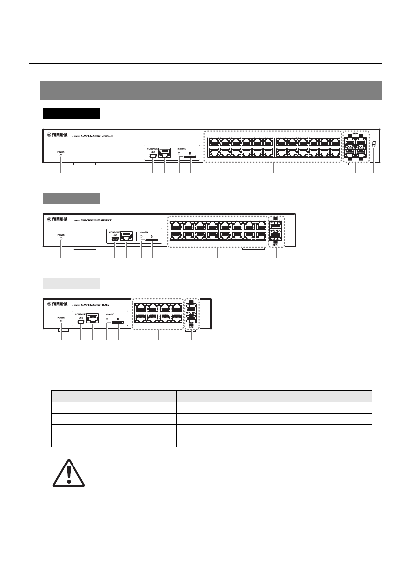
Front Panel
1 POWER indicator
Lights when power is provided to the unit.
POWER indicator Status
Unlit Power off
Flashing (green) Power on, starting up
Lit (green) Power on, normal
Lit (orange) Power on, error occurred
When an abnormal temperature is detected inside this product, the POWER indicator is
lit orange. Reconsider the environment in which this unit is installed, and correctly install
this unit so that its internal temperature is appropriate. You can also check this from
Yamaha LAN Monitor or the Web GUI.
12 SWR2310-28GT SWR2310-18GT SWR2310-10G
Page 13
English
Controls and Connectors
Caution
SWR2310-28GT
SWR2310-18GT
SWR2310-28GT
SWR2310-18GT
SWR2310-28GT
SWR2310-28GT
SWR2310-10G
2
mini-USB CONSOLE port
This is a mini-USB port for making settings. Use a USB cable to connect it to the USB port
of a computer. Use a USB cable equipped with a USB Type A connector and a USB miniB (5-pin) connector.
Memo
Use a cable that supports data transfer. Charge-only cables cannot be used.
3 RJ-45 CONSOLE port
This is an RJ-45 port for making settings. Use an RJ-45/DB-9 console cable to connect it
to the RS-232C connector (COM port) of the computer.
4 microSD indicator
Indicates the connection and usage status of the microSD card.
microSD indicator Status
Unlit A microSD card is not inserted in the slot.
Flashing green The microSD card is being accessed.
Lit green A microSD card is inserted.
Do not remove the microSD card if this indicator is flashing green.
5 microSD slot
A microSD card can be inserted in this slot.
6 LAN ports
7 SFP+ ports /
8 Stack ID indicator
9 SFP ports
These ports support T10BASE-T, 100BASE-TX, and 1000BASE-T.
These ports support T10GBASE-SR, 10GBASE-LR, 1000BASE-SX, and 1000BASE-LX.
Install an SFP+ module or SFP module sold separately by Yamaha. For the SWR2310-
28GT or SWR2310-18GT, install a direct attach cable (DAC-SWRT-3M or DAC-SWRT-1M).
For details on installing an SFP+ or SFP module, refer to “Installing an SFP module”
(page 30) in “Connections.” For details on installing a direct attach cable, refer to “Installing
a direct attach cable” / (page 32). These ports can also
be used for stack connection. For details on stack connection, refer to "Making stack
connections” (page 33).
This is a 7-segment display that indicates the stack ID when stack connection is used.
These ports support 1000BASE-SX and 1000BASE-LX. Install an SFP module sold
separately by Yamaha.
For details on installing an SFP module, refer to “Installing an SFP module” (page 30) in
“Connections.”
SWR2310-28GT SWR2310-18GT SWR2310-10G
13
Page 14
Controls and Connectors
SWR2310-28GT
0
SWR2310-18GT
0 B
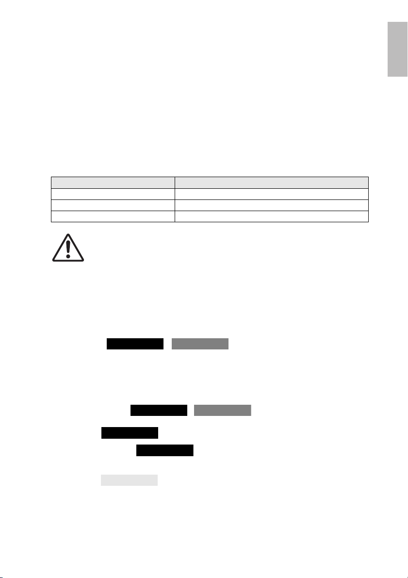
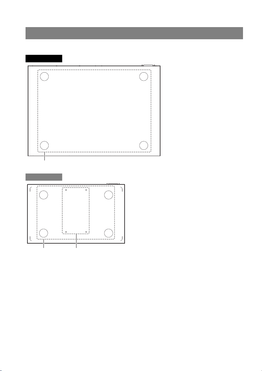
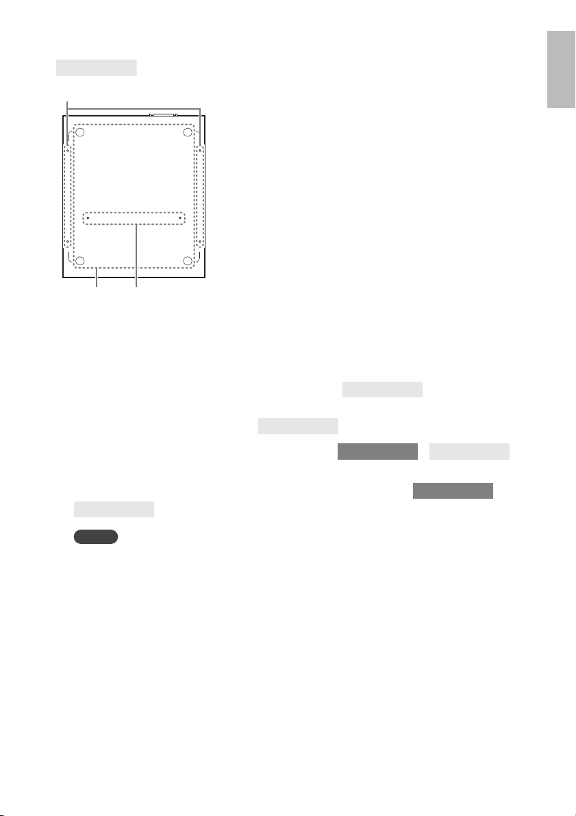
Bottom panel / rear panel / side panel / top panel
° Bottom panel
14 SWR2310-28GT SWR2310-18GT SWR2310-10G
Page 15
English
Controls and Connectors
Notice
SWR2310-10G
0 A
B
SWR2310-10G
SWR2310-10G
SWR2310-18GT
SWR2310-10G
SWR2310-18GT
SWR2310-10G
0
Leg attachment guides
These indicate the locations at which the included legs are to be attached when the unit is
installed in a level location. For details on installation, refer to “Attaching the legs”
(page 20) in “Installation.”
A Rack mount accessory attachment holes
Use these holes to attach the RK-SWR rack mount accessory. For details on installation,
refer to “Installing in a 19-inch rack” (page 21) in “Installation.”
B Wall mount accessory attachment holes /
Use these holes to attach the WK-SWR wall mount accessory.
For details on installation, refer to “Installation on a wall or ceiling” /
(page 24).
Magnet sheets are not supported, and should not be used.
SWR2310-28GT SWR2310-18GT SWR2310-10G
15
Page 16

Controls and Connectors
SWR2310-28GT
D
C
Serial number
SWR2310-18GT
D
C
Serial number
SWR2310-10G
D
C
Serial number
° Rear panel
C Power cord clamp attachment holes
The included power cord clamp (C-shaped) can be attached here. For details on
installation, refer to “Turning the power on” (page 33) in “Connections.”
D Power supply inlet (three-pin connector, C14 type)
Insert the included power supply cord here.
16 SWR2310-28GT SWR2310-18GT SWR2310-10G
Page 17

English
° Side panel
SWR2310-28GT
E G
SWR2310-18GT
E G
SWR2310-10G
G
SWR2310-28GT
F
Serial number
MAC address
° Top panel
Controls and Connectors
SWR2310-28GT SWR2310-18GT SWR2310-10G
17
Page 18

Controls and Connectors
Warning
SWR2310-18GT
F
Serial number
MAC address
SWR2310-10G
F
G
Serial number
MAC address
SWR2310-28GT
SWR2310-18GT
SWR2310-28GT
SWR2310-18GT
E Rack mount accessory attachment holes /
These are used when installing this product in a 19-inch rack (1U). For details on
installation, refer to “Installing in a 19-inch rack” /
(page 23) in “Installation.”
F Product label
This lists the model name, serial number, and MAC address etc. of this unit.
G Cooling vents
The holes in this product are cooling vents for intake of external air.
Do not block the cooling vents or place objects near them.
Doing so could cause fire or malfunctions.
18 SWR2310-28GT SWR2310-18GT SWR2310-10G
Page 19

English
Controls and Connectors
Left
Indicator
LAN ports (upper row)
LAN ports (lower row) SFP/SFP+ ports (lower row)
SFP/SFP+ ports (upper row)
Left
Indicator
Left
Indicator
Left
Indicator
Right
Indicator
Right
Indicator
Right
Indicator
Right
Indicator
Port indicators
These are indicators for the LAN ports and SFP/SFP+ ports, and indicate the state of each
port in each mode.
The indicators show the link status and connection speed of the LAN port or SFP/SFP+
port.
LAN ports
Left indicator Link status Right indicator Connection speed
Unlit
Lit (green)
Flashing (green) Data is flowing. Lit (green)
The link is lost.
(unavailable)
A link is established.
(available)
Unlit
Lit (orange)
Not connected.
Alternatively, connected
by 10BASE-T.
Connected by
100BASE-TX.
Connected by
1000BASE-T.
SFP/SFP+ ports
Left indicator Link status Right indicator Connection speed
Unlit
Lit (green)
Flashing (green) Data is flowing.
The link is lost.
(unavailable)
A link is established.
(available)
SWR2310-28GT SWR2310-18GT SWR2310-10G
Unlit Not connected.
Lit (green)
Connected by
1000BASE-SX/LX or
10GBASE-SR/LR.
If using the DAC-SWRT3M or DAC-SWRT-1M,
connected at 10 Gbps.
19
Page 20

Attaching the legs
Caution
2 4 6 8 10 12 14 16
26
135791113151817201922212423
25
28
27
Leg
Leg
Leg attachment guides
Attaching the legs
As shown in the illustration, attach the included legs in the positions of the leg attachment
guides, and place the unit on a level location such as a desk.
Installation in a rack
Please read before mounting the unit into a rack
• This unit is warrantied to operate in an ambient temperature range of 0–50 °C. If you
install this unit along with other devices into an EIA-standard or JIS-standard rack,
the temperature inside the rack may rise due to heat released from the other
devices, resulting in poor performance of the unit. To prevent the temperature inside
the unit from rising, mount the unit in the rack in accordance with the requirements
below.
• If you plan to rack-mount the unit along with a device that tends to generate heat,
such as an amplifier (excluding an XMV series), be sure to leave a gap of 1U or
more from such devices. Also, be sure to maintain sufficient ventilation in this space
by installing a ventilation panel or leaving it open.
• Open the rear panel of the rack, and place the rack at least 10cm (about four
inches) away from the walls and ceiling to ensure sufficient ventilation. If you cannot
open the rear panel of the rack, install a commercially-available forced ventilation
device, such as a fan kit. If you install a fan kit, closing the rear panel may work
better for heat dissipation purposes. For more information, refer to the owner’s
manual for the rack and/or fan kit.
If you plan to relocate the rack, be sure to first remove this unit from the rack.
If you move the unit while it is still installed in the rack, vibration or physical shock might deform
or damage the rack mount accessory or rack mount hardware, causing injury. There is also a
possibility that this unit might malfunction.
20 SWR2310-28GT SWR2310-18GT SWR2310-10G
Page 21

English
Installation in a rack
Notice
SWR2310-10G
Warning
When attaching this unit to the separately
sold RK-SWR rack mount accessory, you
must use the specified screws that are
included with the rack mount accessory.
If the unit falls, injury or damage might occur.
This could also cause electric shock or
malfunctions.
10
9
Rack mount panel
Screws
Use a Phillips screwdriver
to firmly fasten the screws.
° Installing in a 19-inch rack
The SWR2310-10G is installed using an RK-SWR rack mount accessory sold separately by
Yamaha.
Installation
This section explains how to attach the unit in the middle block of a rack mount panel.
Even if you plan to attach the unit in the left or right block, follow the procedure below.
If the supplied feet have already been attached to the unit, remove them.
1. Attaching the rack mount panel to the unit
Use the two screws supplied with the rack-mount accessory, attach the rack mount panel to
the bottom panel of the unit.
SWR2310-28GT SWR2310-18GT SWR2310-10G
21
Page 22

Installation in a rack
Caution
10
9
19-inch rack
Rack mount panel
[For an EIA standard rack]
[For a JIS standard rack]
Screws supplied
with the 19-inch
rack
Screws supplied
with the 19-inch
rack
SWR2310-10G
SWR2310-10G
2. Install the rack mount panel to the 19-inch rack.
Using the screws that are included with the 19-inch rack (EIA standard 4 pcs., JIS standard
2 pcs.), fasten this unit to the 19-inch rack. Be sure to tighten the screws so that they will not
get loosened.
You can also mount two SWR2310-10G units as shown in the figure below.
9
10
9
10
So as not to obstruct the cooling vents on the top panel of this unit, leave a gap when installing
it in a 19-inch rack.
22 SWR2310-28GT SWR2310-18GT SWR2310-10G
Page 23

English
Installation in a rack
Warning
/
SWR2310-28GT
SWR2310-18GT
2 4 6 8 1
0 1
2 1
4
1
6
2
6
1
3
5 7
9
1
1
1
3 1
5
1
8
1
7
2
0
1
9
2
2
2
1
2
4
2
3
2
5
2
8
2
7
Use a Phillips screwdriver to firmly fasten the screws.
° Installing in a 19-inch rack
The SWR2310-28GT and SWR2310-18GT fit in a 19-inch rack mount 1U size. When installing
them in a 19-inch rack, attach the included rack mount hardware (2 pcs.) using the included
screws (8 pcs.). Here we explain using the SWR2310-28GT as an example.
You must use the included rack mount hardware and screws.
If the unit falls, injury or damage might occur. This could also cause electric shock or malfunctions.
Notice
• If the rack cabinet has a door, take care that it will not interfere with communication cables
or the power cord after this unit is installed.
• So as not to obstruct the cooling vents on the side panels of this unit, leave a gap when
installing it in a 19-inch rack.
Memo
Using the screws that are included with the 19-inch rack (EIA standard 4 pcs., JIS standard 2 pcs.),
fasten this unit to the rack.
The rack mount hardware can be attached to this unit using either of the following two
methods.
Method A
: Attach the rack mount
hardware so that its rack
screw surface is flush with
the front panel of this unit
Method B
: Install the unit 4 cm deeper
than method A (recessed)
If the 19-inch rack cabinet has
a door, use this method of
attachment. Install the unit in a
recessed position so that
cables inserted in the front
panel of the unit do not contact
the door of the rack.
SWR2310-28GT SWR2310-18GT SWR2310-10G
23
Page 24

Installation on a wall or ceiling
Caution
/
SWR2310-18GT
SWR2310-10G
2
4 6 8
1
3 5 7
10
9
2 4 6
8 1
0 1
2
1
41
6
1
8
1
3 5 7 9 1
1 1
3 1
5
1
7
SWR2310-18GT SWR2310-10G
Installation on
a wall or ceiling
Use the separately sold WK-SWR wall mount accessory to install the unit.
If attaching this unit to a ceiling, invert the top and bottom of the unit.
You will need to obtain six screws that fit the holes described in step 1 and are appropriate for
the material and thickness of the wall or ceiling.
Carry out the installation completely, all the way to step 7.
Here we explain using mainly the SWR2310-10G as an example.
• Do not attach this unit to a wall or ceiling that is higher than 2 meters.
If the unit falls, injury or damage might occur.
• When attaching or removing this unit, you must disconnect the unit’s power
plug from the power outlet.
Failing to do so could cause electrical shock or malfunctions.
• Installation must be performed by a qualified installer.
During installation, pay attention to the following points.
• Choose hardware and a location that is well able to support the weight of this unit
• Avoid locations that are subject to sustained vibration
• You must use the specified installation accessory
• Perform periodic maintenance checks
Notice
• The mounting accessory has a surface to which the SWR2310-18GT/SWR2310-10G must
be attached and a surface that must be attached to the wall or ceiling.
If these two surfaces are confused, it will not be possible to attach the mounting accessory
to the SWR2310-18GT/SWR2310-10G. To distinguish the surfaces, refer to the illustrations
for step 1 and step 3.
• The position of the unit relative to the mounting accessory differs by 90 degrees between
the SWR2310-18GT and the SWR2310-10G.
24 SWR2310-28GT SWR2310-18GT SWR2310-10G
Page 25

English
Installation on a wall or ceiling
Warning
Notice
WK-SWRWK-SWR
A
B
C
C
D
D
D
D
B
B
C
C
B
A
A
A
2-R2.5
20
5
ø
10
2-ø5.5
SWR2310-18GT/SWR2310-10G
Attachment surface
(not stamped)
Wall installation
surface
(stamped)
Mark the
wall
Approximately 2 mm
10
9
18
17
B
B
D
D
SWR2310-18GT SWR2310-10G
1. Place the mounting accessory against the wall or ceiling, and mark the
installation location.
2. Provisionally attach four commercially
available screws to the locations that you
marked in step 1.
At this time, leave approximately 2 mm between the
head of the screw and the surface of the wall or ceiling,
allowing room for the mounting accessory to engage the
screws (illustration at right).
You must use screws that are appropriate for the material of the wall or ceiling.
If the unit falls, injury or damage might occur.
3. Align the unit with the mounting accessory (illustration below).
If the supplied feet have already been attached to the unit, remove them.
SWR2310-28GT SWR2310-18GT SWR2310-10G
25
Page 26

Installation on a wall or ceiling
Warning
Notice
Warning
Notice
Warning
A
BBB
CC
DD
BB
CC
A
B
Screw hole for fastening
Screw hole for fastening
4. Using four screws included with the mounting accessory, attach it to the
SWR2310-18G/SWR2310-10G.
Fasten it securely.
• Use only the specified screws that
were included.
If the unit falls, injury or damage might occur.
This could also cause electric shock or
malfunctions.
• Take care when letting your hand or
finger contact the corners of the
mounting accessory.
Inattention might cause injury.
The screw holes to use are stamped with a “D” (SWR2310-18GT) or “B” (SWR2310-10G)
on the mounting accessory.
The screws to use are the small black M3 × 4 screws for the metal chassis.
5. Engage the assembled mounting accessory onto the commercially available
screws that you provisionally attached in step 2, and slide it to the side.
Do not drop the unit.
If the unit falls, injury or damage might occur.
When installing the unit sideways, engage the mounting accessory onto the commercially
available screws, and slide it either to the left or the right.
B
B
B
6. Further tighten the commercially available screws that you provisionally
attached in step 2, fastening the mounting accessory.
7. Install two commercially available screws in the fastening screw holes (two
locations) of the mounting accessory.
26 SWR2310-28GT SWR2310-18GT SWR2310-10G
You must use screws that are appropriate for the material of the wall or ceiling.
If the unit falls, injury or damage might occur.
B
B
Page 27

English
Settings
Settings
Settings for this unit can be made in the following ways.
• Make settings using the Web GUI
• Make settings from the command line using the CONSOLE port
• Make settings from the command line using Telnet
• Make settings from the command line using SSH
This document explains “Make settings using the Web GUI” (page 27) and “Making settings
from the command line using the CONSOLE port” (page 28).
You can log in to this unit either as a standard user or as an administrative user. This
document explains how to log in as an administrative user.
For details on the commands used by this unit, refer to the command reference.
The command reference is available on the Yamaha website.
http://www.yamaha.com/proaudio/
Make settings using the Web GUI
Here we explain the procedure for logging in to this unit using the Web GUI.
You will use Yamaha LAN Monitor to log in to the Web GUI, so install Yamaha LAN Monitor
before you continue.
Before you log in, connect your computer to the same network.
For details on supported web browsers, refer to the Yamaha website.
http://www.yamaha.com/proaudio/
° Logging in to this unit using a web browser
1. Start Yamaha LAN Monitor.
2. Select the device for which you want to make settings, and click the Web
GUI button in the “Device Details” view.
When access is successful, a dialog box appears where you can enter a user name and
password.
3. If you are making settings ahead of time, enter the user name and password,
and click the “log in” button.
With the factory settings, the user name and password are not specified, so it is not
necessary to enter a user name and password.
SWR2310-28GT SWR2310-18GT SWR2310-10G
27
Page 28

Settings
Making settings from the command line using the CONSOLE port
Here we explain the cable, driver, software, and settings that are necessary in order to use the
CONSOLE port.
° Preparing a console cable
• Connect the computer to the CONSOLE port of this unit using a USB cable or an
RJ-45/DB-9 console cable.
• As the USB cable connected to the mini-USB CONSOLE port, use a USB cable that
is equipped with a USB Type A connector and a USB mini-B (5-pin) connector, and
that supports data communication. Charge-only cables cannot be used.
° Installing the USB serial driver
• In order to use the mini-USB CONSOLE port, the USB serial driver must first be
installed in the computer.
• For details on installing the USB serial driver, refer to the “Yamaha Network Device
USB Serial Driver Installation Guide.”
The Yamaha Network Device USB Serial Driver Installation Guide and the installer can be
downloaded from the Yamaha website.
http://www.yamaha.com/proaudio/
° Preparing the computer
You will need terminal software that controls the serial (COM) port of the computer.
Set the parameters of the terminal software as follows.
Parameter Value
Data transmission speed 9600 bps
Character bit length 8
Parity check None
Number of stop bits 1
Flow control Xon/Xoff
If the computer is connected to both the RJ-45 CONSOLE port and the mini-USB
CONSOLE port, only the terminal software that uses the mini-USB CONSOLE port can
make settings.
The messages that are output from this unit are output to both CONSOLE ports.
28 SWR2310-28GT SWR2310-18GT SWR2310-10G
Page 29

English
° Logging in from a computer connected to the CONSOLE port
Notice
1. Using a console cable, connect this unit to the computer.
Connect the computer to the CONSOLE port of this unit using a USB cable or an RJ-45/DB9 console cable.
• The LAN ports and the RJ-45 CONSOLE port all use the same 8-pin connector. If you
connect these wrongly, hardware damage or malfunction might occur.
Take care when making connections.
• If you use the mini-USB CONSOLE port, do not use a USB hub. If multiple Yamaha
switches are connected to one computer, the COM port numbers assigned to the connection might be inadvertently exchanged. Take care that you are not changing the settings of an unintended unit.
2. Check the power supply of this unit.
If this unit is not powered-on, turn on the power as described in “Turning the power on”
(page 33). When this unit powers-on and the command line is usable, a startup message
appears in the console screen of the computer.
If the power is already on, a startup message does not appear.
SWR2310 Rev.2.04.01 (Mon Sep 4 16:28:06 2018)
Copyright (c) 2020 Yamaha Corporation. All Rights
Reserved.
3. Press the <Enter> key.
The system waits for a user name to be entered.
If a user name has already been specified, enter the user name.
When the unit is shipped from the factory, a user name has not been specified, so it need
not be entered.
Settings
Username:
4. Press the <Enter> key.
The system waits for a password to be entered.
If a password has already been specified, enter the password.
When the unit is shipped from the factory, a password has not been specified, so it need not
be entered.
Password:
5. Press the <Enter> key.
If password authentication is successful, the command prompt appears, allowing you to
enter commands.
For details on the commands, refer to the command reference.
SWR2310>
SWR2310-28GT SWR2310-18GT SWR2310-10G
29
Page 30

Connections
Caution
Caution
2 4 6 8 10 12 14 16
26
1357911 13151817201922212423
25
28
27
Computer
SWR2310-10G
SWR2310-28GT
SWR2310-18GT
Protective cap
SFP/SFP+ port
SFP module
Connections
° Connecting to a network device or
a computer
Notice
Do not connect this product to public Wi-Fi
and/or Internet directly.
Only connect this product to the Internet through
a router with strong password-protections.
Consult your router manufacturer for information
on security best practices.
Using LAN cables, connect the LAN port of the network device or computer to the LAN
ports of this unit. If using fiber optic cables to make connections, install an appropriate
SFP module or SFP+ module in an SFP/SFP+ port.
For the installation procedure, refer to “Installing an SFP module” (page 30).
The LAN ports and the RJ-45 CONSOLE port all use the same 8-pin connector. If you connect
these wrongly, hardware damage or malfunction might occur. Take care when making connections.
° Installing an SFP module
• SFP ports ( ):
SFP module (SFP-SWRG-SX,SFP-SWRG-LX)
•SFP+ port ( / ):
SFP+ module (SFP-SWRT-SR, SFP-SWRT-LR),
SFP module (SFP-SWRG-SX, SFP-SWRG-LX)
Supported SFP modules and SFP+ modules are collectively referred to here as SFP
modules.
1.
Remove the dust cover that is affixed to this
unit’s SFP/SFP+ port, and insert the SFP
module.
Memo
Since this unit supports hot-swapping, an SFP module
can be installed without turning the power off.
2. Remove the protective cap from the SFP
module.
30 SWR2310-28GT SWR2310-18GT SWR2310-10G
Do not look into the optical emitter when the SFP module is installed.
The SFP modules separately sold by Yamaha are class 1 laser devices. They may emit
laser beams invisible to the eye. If the laser beam enters your eye, your eyesight might be
damaged.
Page 31

English
Connections
Caution
Connector
Fiber optic cable
Fiber optic cable
Connector
Lever
3. To the connector, connect a fiber optic cable
that is suitable for each module.
° Removing an SFP module
Secure this unit so that it will not move, and while grasping the lever of the SFP module,
pull it slowly toward yourself to remove the module from the SFP/SFP+ port.
Supported SFP modules and SFP+ modules are collectively referred to here as SFP
modules.
1. Detach the fiber optic cable.
2. If the SFP module is connected to the upper
row of ports, lower the SFP module’s lever.
If it is connected to the lower row of ports, raise the lever.
Do not look into the optical emitter when the SFP module is installed.
The SFP modules separately sold by Yamaha are class 1 laser devices. They may emit
laser beams invisible to the eye. If the laser beam enters your eye, your eyesight might be
damaged.
3. Grasp the lever and pull out the SFP module.
Memo
Since this unit supports hot-swapping, an SFP module can be
removed without turning the power off.
SWR2310-28GT SWR2310-18GT SWR2310-10G
31
Page 32

Connections
Caution
/
SWR2310-28GT
SWR2310-18GT
SFP+ port
SFP+ module
Protective cap
Removal tab
/
SWR2310-28GT
SWR2310-18GT
Removal tab
Removal tab
° Installing a direct attach cable
A direct attach cable (DAC-SWRT-3M, DAC-SWRT-1M) can be installed in an SFP+ port of
the SWR2310-28GT or SWR2310-18GT.
1. Remove the protective cap from the SFP+ module section of the direct
attach cable, and remove the dust cover from the SFP+ port of this unit.
2. Grasp the SFP+ module section of the direct attach cable, insert it firmly into
the SFP+ port of this unit, and engage the lock.
SFP+
SFP+
Locked
Unlocked
° Removing a direct attach cable
1. While using one hand to push the SFP+ module section inward, use the
other hand to pull the removal tab toward yourself, disengaging the lock.
2. When the lock disengages, continue pulling the removal tab and slowly pull
out the SFP+ module section.
SFP+
• Do not grasp the cable of the direct attach cable when disconnecting it. Doing so might
cause malfunctions.
• Do not disconnect the cable by pulling only the removal tab. Doing so might cause
malfunctions.
• First verify that the lock is disengaged, and then disconnect the cable. Forcibly
disconnecting the cable will damage the direct attach cable or cause this unit to
malfunction.
32 SWR2310-28GT SWR2310-18GT SWR2310-10G
Page 33

English
Connections
Caution
SWR2310-28GT
SWR2310-28GT
SWR2310-18GT
SWR2310-28GT
SWR2310-18GT
Insert the included clamp
into the holes of the unit.
1 Raise the clamp. 2 Connect the power cord. 3 Press down on the
clamp to secure the
power cord.
° Making stack connections
Attach a direct attach cable or an SFP+ module (SFP-SWRT-SR or SFP-SWRT-LR) to an
SFP+ port of the SWR2310-28GT. If using an SFP+ module, you must additionally provide a
fiber optic cable that is suitable for the SFP+ module.
For details on installing or removing a direct attach cable, refer to “Installing a direct attach
cable” / (page 32) and “Removing a direct attach cable”
/ (page 32).
For the procedure of installing an SFP+ module, refer to “Installing an SFP module” (page 30).
For details on stack connections, refer to the SWR2310 series “Technical Reference.”
° Turning the power on
1. Attach the included power cord clamp.
To prevent accidental disconnection of the power cord, insert the
included power cord clamp (“included clamp” in the illustration at
right) into the power cord clamp holes of the unit (“holes in the
unit” in the illustration at right) and secure the power cord.
• The included power cord clamp is only for the included
power supply cord.
• If you use the clamp for other power cords, they might be
damaged or might not secure properly.
2.
Connect the included power cord to the power inlet, and secure it with the clamp.
3. Connect the power cord to an electrical outlet.
The POWER indicator flashes green, and after startup is completed, is lit green.
If the POWER indicator is lit orange, the temperature inside the unit is abnormal.
Reconsider the environment in which this unit is installed, and correctly install this unit so
that its internal temperature is appropriate.
4. Check the port indicators.
If the left indicator (LINK/ACT) of ports connected to a network device or a computer is lit
green or flashing green, the status is normal.
[If the left indicator of the port (LINK/ACT) is not lit green or flashing green]
Check whether the cable is correctly connected to the port, and whether the connected
network device or computer is powered-on.
For details on the connection status, refer to “Port indicators” (page 19).
SWR2310-28GT SWR2310-18GT SWR2310-10G
33
Page 34

Initialization
NOTE
Initialization
This unit can be restored to its factory-set state in the following ways.
• Using the Web GUI to restore the factory settings (page 34)
• Using the cold start command to restore the factory settings (page 35)
• Entering the [I] (uppercase I) key during startup to restore the factory settings (page 35)
Notice
When restoring the factory settings, note the following points.
• All communication is halted immediately after execution.
• When you execute this, the settings will also return to their factory-set state. If necessary,
use external memory to save the settings before you proceed with initialization. For details
on how to export settings to external memory, refer to the SWR2310 series “Technical
Reference.”
° Using the Web GUI to restore the factory settings
This unit can be restored to its factory-set state by making settings from the Web GUI.
Log in to the Web GUI from Yamaha LAN Monitor.
1. Choose “Administration” tab – “Maintenance” – “Restart or Initialize.”
The “Restart or Initialize” screen appears.
2. In the “Initialize” section, click the “Proceed” button.
The “Initialize” screen appears.
3. Enter the administrative password, and click “Confirm.”
The “Confirm execution” screen appears.
4. Verify the content, and click the “Execute” button.
The unit is returned to its factory-set state. Also, the “Initialization” dialog box appears, and
the unit restarts.
5. After this unit has finished restarting, access the Web GUI once again from
Yamaha LAN Monitor.
During restart, the computer on which the Web GUI is open will be unable to communicate with the
unit (the status indication of the computer’s network adapter will be “Network cable is not
connected”), but the communication status will recover when restart is completed. After this unit’s
POWER indicator has finished flashing, verify that communication has been restored for the
computer on which the Web GUI is open, and then click the Web GUI button in the “Device Details”
view.
34 SWR2310-28GT SWR2310-18GT SWR2310-10G
Page 35

English
Initialization
° Using the cold start command to restore the factory settings
You can return the unit to its factory settings by using a command line setting via the
CONSOLE port, Telnet, or an SSH client.
Here we assume that you are logged in as described in “Logging in from a computer
connected to the CONSOLE port” (page 29).
1. Enter enable, and press the <Enter> key.
You are now in privileged EXEC mode.
SWR2310>enable
SWR2310#
2. Enter the cold start command, and press the <Enter> key.
You will be asked to enter the administrative password.
If a password has already been specified, enter the password.
When the unit is shipped from the factory, a password has not been specified, so it need not
be entered.
SWR2310#cold start
Password:
3. Press the <Enter> key.
The unit returns to the factory-set state, and then restarts.
° Entering the [I] (uppercase I) key during startup to restore the factory
settings
The unit can be restored to its factory settings by entering an uppercase “I” when the unit
is starting up. This explanation uses the method of disconnecting and reconnecting the
power cord. The procedure is also the same when using the reload command to restart
this unit.
Notice
Here we assume that you are logged in as described in “Logging in from a computer
connected to the CONSOLE port” (page 29).
1. Disconnect and then reconnect the power cord of this unit.
2. After restart, enter an uppercase “I” within one second after the BootROM
Ver (see below) appears on the console screen.
SWR2310 BootROM Ver.1.00
Memo
Before the BootROM Ver appears on the console screen, you can press the [Caps Lock] key or
hold down the [Shift] key so that you will be ready to enter an uppercase “I” immediately.
3. When a screen asks you whether to execute initialization, press the <y> key
to execute initialization.
Initialize or not ?(y/n)
Initialization is executed.
Ready to Initialize
...............
SWR2310-28GT SWR2310-18GT SWR2310-10G
35
Page 36

Appendix
Appendix
Hardware specifications
Item SWR2310-28GT SWR2310-18GT SWR2310-10G
Dimensions
(W x D x H units: mm)
not including protrusions and
Weight (without included
Power supply voltage and
CONSOLE
LAN ports
feet
items)
frequency
Maximum power
consumption
port
transmission
Communicati
Standard RS-232C, USB 2.0
Connector RJ-45, USB mini-B (5-pin)
Data
speed
Standard IEEE802.3 (10BASE-T/100BASE-TX/1000BASE-T)
Number of
ports
on mode
Connector RJ-45
Polarity Automatic detection of straight/cross, or fixed at straight
440 mm(W) x
300 mm(D) x
44.0 mm(H)
3.9kg 2.1kg 1.7kg
25.2 W 19.0 W 11.7 W
24 16 8
330 mm(W) x
200 mm(D) x
43.5 mm(H)
AC100 – 240V, 50/60 Hz
9600 bit/s
Auto negotiation
220 mm(W) x
250 mm(D) x
40.5 mm(H)
Standard
SFP+ ports
Number of
ports
Standard –
SFP ports
Number of
ports
IEEE802.3z (1000BASE-SX/ 1000BASE-LX),
IEEE802.3ae (10GBASE-SR/ 10GBASE-LR)
42 –
–2
36 SWR2310-28GT SWR2310-18GT SWR2310-10G
–
IEEE802.3z
(1000BASE-SX/
1000BASE-LX)
Page 37

English
Item SWR2310-28GT SWR2310-18GT SWR2310-10G
microSD
slot
MAC address Indicated in product label on top panel of unit
Standard microSD/microSDHC (microSDXC is not supported)
Indicators
File
System
POWER, microSD,
STACK ID,
LAN port (LINK/
ACT, SPEED),
SFP+ port (LINK/
ACT, SPEED)
FAT/FAT32
POWER, microSD,
LAN port (LINK/ACT,
SPEED), SFP+ port
(LINK/ACT, SPEED)
Appendix
POWER, microSD,
LAN port (LINK/ACT,
SPEED),
SFP port (LINK/ACT,
SPEED)
Operating
environment
conditions
Storage
environment
conditions
Included items
Ambient
temperature
Ambient
humidity
Ambient
temperature
Ambient
humidity
15–80% (non-condensing)
10–90% (non-condensing)
Owner’s manual (this document),
power cord (3-prong), power cord clamp, legs
19-inch rack mount hardware and screws –
0–50 °C
-20–60 °C
The explanations in this document use the current specifications as of the date of
publication. The latest version can be downloaded from the Yamaha website.
http://www.yamaha.com/proaudio/
SWR2310-28GT SWR2310-18GT SWR2310-10G
37
Page 38

Appendix
SWR2310-28GT
246810121416
26
135791113151817201922212423
25
28
27
440
47.2
443.2
300
2.3
Units: mm
SWR2310-18GT
2 4 6 8 10 12 14 16
18
13579111315
17
330
46.7
43.53.2
200
2.3
Units: mm
Dimensional diagram
38 SWR2310-28GT SWR2310-18GT SWR2310-10G
Page 39

English
RJ-45/DB-9 console cable pin configuration
SWR2310-10G
2468
1357
10
9
220
43.5
40.53
250
2.3
Units: mm
Console (RS-232C)
Signal
RTS
DTR
TxD
GND
GND
RxD
DSR*
CTS*
1
2
3
4
5
6
7
8
8
6
9
2
5
3
7
4
1
RJ-45 D-SUB 9
The model number, serial number, power requirements, etc., may be found
on or near the name plate, which is at the top of the unit. You should note this
serial number in the space provided below and retain this manual as a
permanent record of your purchase to aid identification in the event of theft.
Model No.
Serial No.
(top_en_01)
Appendix
* DSR and CTS signals are not used by the SWR2310 series.
SWR2310-28GT SWR2310-18GT SWR2310-10G
39
Page 40

Appendix
Software license agreement
This License Agreement (the “AGREEMENT”) is a legal agreement between you and Yamaha
Corporation (“YAMAHA”) under which YAMAHA is providing the firmware of YAMAHA’s network
products (the “PRODUCT”) and related software program, documentation and electronic files
(collectively, the “SOFTWARE”).
YAMAHA grants you a personal non-exclusive license to use the SOFTWARE only for purposes of
running it on the PRODUCT.
This AGREEMENT applies to the SOFTWARE which YAMAHA provides you and the installed copy
thereof, subject to the provision of 1-1 herein, into the PRODUCT or personal computer owned by you.
1. GRANT OF LICENSE:
1-1. YAMAHA grants you a personal non-exclusive license to install the SOFTWARE and use
the SOFTWARE on the PRODUCT or other devices, including but not limited to the
personal computer, which you own.
1-2. You shall not assign, sublicense, sell, rent, lease, loan, convey or otherwise transfer to any
third party, upload to a website or a server computer to which specified or unspecified
persons may access, or copy, duplicate, translate or convert to another programming
language the SOFTWARE except as expressly provided herein. You shall not alter, modify,
disassemble, decompile or otherwise reverse engineer the SOFTWARE and you also shall
not have any third party to do so.
1-3. You shall not modify, remove or delete a copyright notice of YAMAHA contained in the
SOFTWARE.
1-4. Except as expressly provided herein, no license or right, express or implied, is hereby
conveyed or granted by YAMAHA to you for any intellectual property of YAMAHA.
2. OWNERSHIP AND COPYRIGHT:
The SOFTWARE is protected under the copyright laws and owned by YAMAHA. You agree and
acknowledge that YAMAHA transfers neither ownership interest nor intellectual property in the
SOFTWARE to you under this AGREEMENT or otherwise.
3. EXPORT RESTRICTIONS:
You agree to comply with all applicable export control laws and regulations of the country
involved, and not to export or re-export, directly or indirectly, the SOFTWARE in violation of any
such laws and regulations.
4. SUPPORT AND UPDATE:
YAMAHA, YAMAHA’s subsidiaries and affiliates, their distributors and dealers are not responsible
for maintaining or helping you to use the SOFTWARE. No updates, bug-fixes or support will be
made available to you for the SOFTWARE.
5. DISCLAIMER OF WARRANTY:
5-1. THE SOFTWARE IS PROVIDED “AS IS” WITHOUT WARRANTY OF ANY KIND, EITHER
EXPRESS OR IMPLIED, INCLUDING, BUT NOT LIMITED TO THE IMPLIED
WARRANTIES OF MERCHANTABILITY AND FITNESS FOR A PARTICULAR PURPOSE.
5-2. IN NO EVENT SHALL YAMAHA, YAMAHA’S SUBSIDIARIES AND AFFILIATES, THEIR
DISTRIBUTORS AND DEALERS BE LIABLE FOR ANY DAMAGES WHATSOEVER
(INCLUDING WITHOUT LIMITATION, LOSS OF BUSINESS PROFITS, LOSS OF
BUSINESS INFORMATION, LOSS OF BUSINESS INTERRUPTION OR OTHER
INCIDENTAL OR CONSEQUENTIAL DAMAGES) ARISING OUT OF THE SOFTWARE,
USE THEREOF, OR INABILITY TO USE THEREOF EVEN IF YAMAHA, YAMAHA’S
SUBSIDIARIES AND AFFILIATES, THEIR DISTRIBUTORS OR DEALERS HAVE BEEN
ADVISED OF THE POSSIBILITY OF SUCH DAMAGES. SOME STATES DO NOT ALLOW
THE LIMITATION OR EXCLUSION OF LIABILITY FOR INCIDENTAL OR
40 SWR2310-28GT SWR2310-18GT SWR2310-10G
Page 41

English
Appendix
CONSEQUENTIAL DAMAGES, SO THE ABOVE LIMITATION OR EXCLUSION MAY NOT
APPLY TO YOU. SOME STATES DO NOT ALLOW THE LIMITATION OR EXCLUSION OF
LIABILITY FOR INCIDENTAL OR CONSEQUENTIAL DAMAGES, SO THE ABOVE
LIMITATION OR EXCLUSION MAY NOT APPLY TO YOU.
5-3. YAMAHA, YAMAHA’S SUBSIDIARIES AND AFFILIATES, THEIR DISTRIBUTORS AND
DEALERS SHALL HAVE NO OBLIGATION TO INDEMNIFY YOU AGAINST ANY CLAIM
OR SUIT BROUGHT BY A THIRD PARTY ALLEGING THAT THE SOFTWARE OR USE
THEREOF INFRINGES ANY INTELLECTUAL PROPERTY OF SUCH THIRD PARTY.
6. TERM:
6-1. This AGREEMENT becomes effective upon your agreeing to the terms and conditions
herein and continues in effect unless or until terminated in accordance with the provision of
6-2 or 6-3 herein.
6-2. You may terminate this AGREEMENT by deleting the SOFTWARE installed into the
PRODUCT.
6-3. This AGREEMENT will also terminate if you fail to comply with any of the terms and
conditions of this AGREEMENT.
6-4. In case this AGREEMENT is terminated in accordance with the provision 6-3, you shall
promptly delete the SOFTWARE.
6-5. Notwithstanding anything contains herein, Sections 2 through 6 shall survive any
termination or expiration hereof.
7. SEPARABILITY:
In the event that any provision of this AGREEMENT is declared or found to be illegal by any court
or tribunal of competent jurisdiction, such provision shall be null and void with respect to the
jurisdiction of that court or tribunal and all the remaining provisions of this AGREEMENT shall
remain in full force and effect.
8. U.S. GOVERNMENT RESTRICTED RIGHTS NOTICE:
The Software is a “commercial item,” as that term is defined at 48 C.F.R. 2.101 (Oct 1995),
consisting of “commercial computer software” and “commercial computer software
documentation,” as such terms are used in 48 C.F.R. 12.212 (Sept 1995). Consistent with 48
C.F.R. 12.212 and 48 C.F.R. 227.7202-1 through 227.72024 (June 1995), all U.S. Government
End Users shall acquire the Software with only those rights set forth herein.
9. ACKNOWLEDGMENT:
You agree that this AGREEMENT is the complete and exclusive statement of agreement between
you and YAMAHA concerning the subject matter hereof and supersedes all proposals or prior
agreements, verbal or written, and any other communications between you and the parties
relating to the subject matter hereof. NO amendment to this AGREEMENT shall be effective
unless signed by a duly authorized representative of YAMAHA.
10. GOVERNING LAW:
This AGREEMENT shall be governed by and construed in accordance with the laws of Japan
without reference to the principles of conflict of laws.
SWR2310-28GT SWR2310-18GT SWR2310-10G
41
Page 42

Index
C
Cold start command.................................. 35
Command line........................................... 28
CONSOLE port ......................................... 28
Cooling vents ............................................ 18
D
Direct attach cable .................................... 32
I
Initialization ............................................... 34
L
LAN ports.................................................. 13
Leg............................................................ 20
Leg attachment guides.............................. 15
M
microSD indicator...................................... 13
microSD slot.............................................. 13
mini-USB CONSOLE port ................... 13, 28
P
Password .................................................. 27
Power cord clamp ..................................... 33
Power cord clamp attachment holes......... 16
POWER indicator...................................... 12
Power supply inlet..................................... 16
Product label ............................................. 18
S
SFP ports ..................................................13
SFP+ module ............................................ 30
SFP+ ports ................................................ 13
Stack connections ..................................... 33
Stack ID indicator ...................................... 13
U
User name................................................. 27
W
Wall mount accessory attachment holes... 15
Web GUI ................................................... 27
WK-SWR................................................... 24
Y
Yamaha LAN Monitor.......................... 11, 27
Yamaha network device
USB serial driver .................................11, 28
R
Rack mount accessory
attachment holes................................. 15, 18
RJ-45 CONSOLE port............................... 13
RK-SWR ................................................... 20
42 SWR2310-28GT SWR2310-18GT SWR2310-10G
Page 43

English
Memo
SWR2310-28GT SWR2310-18GT SWR2310-10G 43
Page 44

产品中有害物质的名称及含量
部件名称
有害物质
铅(Pb) 汞(Hg) 镉(Cd)
六价铬
(Cr(VI))
多溴联苯
(PBB)
多溴二苯醚
(PBDE)
电路板×○○○○○
○○○○○○
○○○○○○
○○○○○○
○○○○○○
○○○○○○
外壳箱体
线缆
金属配件
塑料配件
标签
本表格依据
SJ/T 11364的规定编制。
○
: 表示该有害物质在该部件所有均质材料中的含量均在 GB/T 26572 规定的限量要
求以下。
×
: 表示该有害物质至少在该部件的某一均质材料中的含量超出 GB/T 26572 规定的
限量要求。
此标识适用于在中华人民共和国销售的电器电子产品。标识中间的数字为环
保使用期限的年数。
ҙ䗖⫼Ѣ䴲⛁ᏺ⇨ᴵӊϟᅝܼՓ⫼DŽ
NJŨǶŨǨƍƱƾƦǽŲƱƉƾƎǾƉšǨƍȡšDZźǾǘƍǵƍƱƯƥǩƨȓŲǵȋƍƍȡŦšȜƍǷǩƨŷnjųȢŲǧǸŲǙƣȌƒdzŤȋƍǖŻȢŨƲŦIJ
ŐāŌŖŢāŜāǶřāǼŢāĹʼnŎāĹŚŢŜāŎŢʼnāŊŖŢāŜāǶřāĸŬāʼnŘāĿŪʼnāŎŪŇāŌŪŇāɄŬŇāɎŜāŖȬŜă
ēØīĀĐÀĬāīõȼāåī´Ù¼È¼ÕīÀĶĪØīÉī´·Ù¸äĬȸąīāīô·ğ¸Čç¸ÁĀ¼Àòīááī´ĩÚIJ¼è
ҙ䗖⫼Ѣ⍋ᢨ 2000m ҹϟഄᅝܼՓ⫼DŽ
PŢȓŤȋƍǨƍǪǽŷŭȤǩƨǫȏŲȓůȄŨŷǝŨșŨȡƈȤƍƱȌƒšȜƍǷǩƨŷnjųȢŲǧǸŲǙƣȌƒdzůȅƍǖŻȢŨƲŦIJ
ȄāŎŐǑŖŢāĻŬŜāřŜāŎņŬāŐŇāɥŢā2000ŎʼnāǼŢāŜāǶřāĸŬāʼnŘāĿŪʼnāŎŪŇāŌŪŇāɄŬŇāɎŜāŖȬŜă
ĊĪØĪÛĜIJÜīýĢ×2000ēØīĀĐÀĬāīõȼāåī´Ù¼È¼ÕīÀĶĪ×ÙĶĈĐIJ·Ùć»ğĘÈÚÉģĄ
݇ѢѻકϞ᠔⼎ⱘˈ䇋ᣝ✻ⳌᑨⱘϞ䗄䇈ᯢ䖯㸠᪡DŽ
ƾƦȏƧǧųǫȏŲǩƨƱȊŲǧųȡŰŶǶŲȤǖųŽǶŲǫǽŲƱȀƍǽźǥŦȊŲDZȏŲǤŞžȊŲǧųȢŲǖŸȊŨŽǷǂƎȤŷȄŨŷȋƍǖŻȢŨǷȓŨǘƉȀƍǽźǥŦȊŲDZȏŲǤȅƉȊŨǦŨȢŨǨƍǷƍƱšșźǷǶŨǦŨȢŨŷIJ
ņŬʼnāɲŜāȪŪĻāĹŢāŇŊŪāȪŬʼnāŘŢŜāŇɎŢŌŜāǤŢāĹŜřāȨŘāȭāŌŪŇāɄŬŇāĹŅŬĻāŇĹŬŜă
Εϻةδϫϣ ϰϜϯΪϯΘγث ϰϨϯϟΒϨϯγ αΎϣ εتέتΪϧηث ϯϳϮΑ Εϻةϐηϣ נϯϠϯϗ .
Doiq gijdoz veh youq gwnz canjbinj haenx, cingj mwngz ciuq gijsaw sij youq gwnzdoz doiqndei le menh baezyamq
baezyamq ma guh.
Dan hab yungh youq gij dienheiq diuzgen mbouj dwg diegndat haenx ancienz sawjyungh.
Dan hab yungh youq gij digih haijbaz 2 000m doxroengz haenx ancienz sawjyungh.
44 SWR2310-28GT SWR2310-18GT SWR2310-10G
Page 45

SWR2310-28GT SWR2310-18GT SWR2310-10G 45
Page 46

Information for users on collection and disposal of old equipment:
This symbol on the products, packaging, and/or accompanying documents means that used electrical
and electronic products should not be mixed with general household waste.
For proper treatment, recovery and recycling of old products, please take them to applicable collection
points, in accordance with your national legislation.
By disposing of these products correctly, you will help to save valuable resources and prevent any
potential negative effects on human health and the environment which could otherwise arise from
inappropriate waste handling.
For more information about collection and recycling of old products, please contact your local municipality,
your waste disposal service or the point of sale where you purchased the items.
For business users in the European Union:
If you wish to discard electrical and electronic equipment, please contact your dealer or supplier for further information.
Information on Disposal in other Countries outside the European Union:
This symbol is only valid in the European Union. If you wish to discard these items, please contact your local authorities or
dealer and ask for the correct method of disposal.
(weee_eu_en_02)
Verbraucherinformation zur Sammlung und Entsorgung alter Elektrogeräte
Befindet sich dieses Symbol auf den Produkten, der Verpackung und/oder beiliegenden Unterlagen, so
sollten benutzte elektrische Geräte nicht mit dem normalen Haushaltsabfall entsorgt werden.
In Übereinstimmung mit Ihren nationalen Bestimmungen bringen Sie alte Geräte bitte zur fachgerechten
Entsorgung, Wiederaufbereitung und Wiederverwendung zu den entsprechenden Sammelstellen.
Durch die fachgerechte Entsorgung der Elektrogeräte helfen Sie, wertvolle Ressourcen zu schützen, und
verhindern mögliche negative Auswirkungen auf die menschliche Gesundheit und die Umwelt, die
andernfalls durch unsachgerechte Müllentsorgung auftreten könnten.
Für weitere Informationen zum Sammeln und Wiederaufbereiten alter Elektrogeräte kontaktieren Sie bitte Ihre
örtliche Stadt- oder Gemeindeverwaltung, Ihren Abfallentsorgungsdienst oder die Verkaufsstelle der Artikel.
Information für geschäftliche Anwender in der Europäischen Union:
Wenn Sie Elektrogeräte ausrangieren möchten, kontaktieren Sie bitte Ihren Händler oder Zulieferer für weitere Informationen.
Entsorgungsinformation für Länder außerhalb der Europäischen Union:
Dieses Symbol gilt nur innerhalb der Europäischen Union. Wenn Sie solche Artikel ausrangieren möchten, kontaktieren Sie
bitte Ihre örtlichen Behörden oder Ihren Händler und fragen Sie nach der sachgerechten Entsorgungsmethode.
(weee_eu_de_02)
Informations concernant la collecte et le traitement des déchets d’équipements
électriques et électroniques
Le symbole sur les produits, l’emballage et/ou les documents joints signifie que les produits électriques
ou électroniques usagés ne doivent pas être mélangés avec les déchets domestiques habituels.
Pour un traitement, une récupération et un recyclage appropriés des déchets d’équipements électriques et électroniques, veuillez les déposer aux points de collecte prévus à cet effet, conformément à la réglementation nationale.
En vous débarrassant correctement des déchets d’équipements électriques et électroniques, vous
contribuerez à la sauvegarde de précieuses ressources et à la prévention de potentiels effets négatifs sur
la santé humaine qui pourraient advenir lors d’un traitement inapproprié des déchets.
Pour plus d’informations à propos de la collecte et du recyclage des déchets d’équipements électriques
et électroniques, veuillez contacter votre municipalité, votre service de traitement des déchets ou le point
de vente où vous avez acheté les produits.
Pour les professionnels dans l’Union européenne :
Si vous souhaitez vous débarrasser des déchets d’équipements électriques et électroniques, veuillez contacter votre vendeur ou fournisseur pour plus d’informations.
Informations sur la mise au rebut dans d’autres pays en dehors de l’Union européenne :
Ce symbole est seulement valable dans l’Union européenne. Si vous souhaitez vous débarrasser de déchets d’équipements électriques et électroniques, veuillez contacter les autorités locales ou votre fournisseur et demander la méthode de traitement appropriée.
(weee_eu_fr_02)
46 SWR2310-28GT SWR2310-18GT SWR2310-10G
Page 47

Información para usuarios sobre la recogida y eliminación de los equipos antiguos
Este símbolo en los productos, embalajes y documentos anexos significa que los productos eléctricos y
electrónicos no deben mezclarse con los desperdicios domésticos normales.
Para el tratamiento, recuperación y reciclaje apropiados de los productos antiguos, llévelos a puntos de
reciclaje correspondientes, de acuerdo con la legislación nacional.
Al deshacerse de estos productos de forma correcta, ayudará a ahorrar recursos valiosos y a impedir los
posibles efectos desfavorables en la salud humana y en el entorno que de otro modo se producirían si se
trataran los desperdicios de modo inapropiado.
Para obtener más información acerca de la recogida y el reciclaje de los productos antiguos, póngase en
contacto con las autoridades locales, con el servicio de eliminación de basuras o con el punto de venta
donde adquirió los artículos.
Para los usuarios empresariales de la Unión Europea:
Si desea desechar equipos eléctricos y electrónicos, póngase en contacto con su vendedor o proveedor para obtener más
información.
Información sobre la eliminación en otros países fuera de la Unión Europea:
Este símbolo solo es válido en la Unión Europea. Si desea desechar estos artículos, póngase en contacto con las
autoridades locales o con el vendedor y pregúnteles el método correcto.
(weee_eu_es_02)
Informações para os utilizadores relativas à recolha e eliminação de
equipamentos usados
Este símbolo, presente em produtos, embalagens e/ou incluído na documentação associada, indica que
os produtos elétricos e eletrónicos usados não devem ser eliminados juntamente com os resíduos
domésticos em geral.
O procedimento correto consiste no tratamento, recuperação e reciclagem de produtos usados, pelo que
deve proceder à respetiva entrega nos pontos de recolha adequados, em conformidade com a
legislação nacional em vigor.
A eliminação destes produtos de forma adequada permite poupar recursos valiosos e evitar potenciais efeitos
prejudiciais para a saúde pública e para o ambiente, associados ao processamento incorreto dos resíduos.
Para mais informações relativas à recolha e reciclagem de produtos usados, contacte as autoridades
locais, o serviço de eliminação de resíduos ou o ponto de venda onde foram adquiridos os itens relevantes.
Informações para utilizadores empresariais na União Europeia:
Para proceder à eliminação de equipamento elétrico e eletrónico, contacte o seu revendedor ou fornecedor para obter
informações adicionais.
Informações relativas à eliminação em países não pertencentes à União Europeia:
Este símbolo é válido exclusivamente na União Europeia. Caso pretenda eliminar este tipo de itens, contacte as autoridades
locais ou o seu revendedor e informe-se acerca do procedimento correto para proceder à respetiva eliminação.
(weee_eu_pt_02)
Informazioni per gli utenti sulla raccolta e lo smaltimento di vecchia attrezzatura
Questi simboli sui prodotti, sull’imballaggio e/o sui documenti che li accompagnano, indicano che i
prodotti elettrici ed elettronici non devono essere mischiati con i rifiuti generici.
Per il trattamento, il recupero e il riciclaggio appropriato di vecchi prodotti, si prega di portarli ai punti di
raccolta designati, in accordo con la legislazione locale.
Smaltendo correttamente questi prodotti si potranno recuperare risorse preziose, oltre a prevenire
potenziali effetti negativi sulla salute e l’ambiente che potrebbero sorgere a causa del trattamento
improprio dei rifiuti.
Per ulteriori informazioni sulla raccolta e il riciclaggio di vecchi prodotti, si prega di contattare
l’amministrazione comunale locale, il servizio di smaltimento dei rifiuti o il punto vendita dove sono stati
acquistati gli articoli.
Per utenti imprenditori dell’Unione europea:
Se si desidera scartare attrezzatura elettrica ed elettronica, si prega di contattare il proprio rivenditore o il proprio fornitore per
ulteriori informazioni.
Informazioni sullo smaltimento negli altri Paesi al di fuori dell’Unione europea:
Questi simboli sono validi solamente nell’Unione Europea; se si desidera scartare questi articoli, si prega di contattare le
autorità locali o il rivenditore e richiedere informazioni sulla corretta modalità di smaltimento.
(weee_eu_it_02)
SWR2310-28GT SWR2310-18GT SWR2310-10G 47
Page 48

ADDRESS LIST
Head Office/Manufacturer: Yamaha Corporation 10-1, Nakazawa-cho, Naka-ku, Hamamatsu, 430-8650, Japan
(For European Countries) Importer: Yamaha Music Europe GmbH Siemensstrasse 22-34, 25462 Rellingen, Germany
CANADA
Yamaha Canada Music Ltd.
135 Milner Avenue, Toronto, Ontario,
M1S 3R1, Canada
Tel: +1-416-298-1311
U.S.A.
Yamaha Corporation of America
6600 Orangethorpe Avenue, Buena Park, CA 90620,
U.S.A.
Tel: +1-714-522-9011
MEXICO
Yamaha de México, S.A. de C.V.
Av. Insurgentes Sur 1647 Piso 9, Col. San José
Insurgentes, Delegación Benito Juárez, México,
D.F., C.P. 03900, México
Tel: +52-55-5804-0600
BRAZIL
Yamaha Musical do Brasil Ltda.
Rua Fidêncio Ramos, 302 Cj 52 e 54 Torre B Vila
Olímpia CEP 04551-010 São Paulo/SP, Brazil
Tel: +55-11-3704-1377
ARGENTINA
Yamaha Music Latin America, S.A.,
Sucursal Argentina
Olga Cossettini 1553, Piso 4 Norte,
Madero Este-C1107CEK,
Buenos Aires, Argentina
Tel: +54-11-4119-7000
PANAMA AND OTHER LATIN
AMERICAN COUNTRIES/
CARIBBEAN COUNTRIES
Yamaha Music Latin America, S.A.
Edif. Torre Banco General, Piso 7, Urbanización
Marbella, Calle 47 y Aquilino de la Guardia,
Ciudad de Panamá, República de Panamá
Tel: +507-269-5311
THE UNITED KINGDOM/IRELAND
Yamaha Music Europe GmbH (UK)
Sherbourne Drive, Tilbrook, Milton Keynes,
MK7 8BL, U.K.
Tel: +44-1908-366700
GERMANY
Yamaha Music Europe GmbH
Siemensstrasse 22-34, 25462 Rellingen , Germany
Tel: +49-4101-303-0
SWITZERLAND/LIECHTENSTEIN
Yamaha Music Europe GmbH, Branch
Switzerland in Thalwil
Seestrasse 18a, 8800 Thalwil, Switzerland
Tel: +41-44-3878080
AUSTRIA/BULGARIA/
CZECH REPUBLIC/HUNGARY/
ROMANIA/SLOVAKIA/SLOVENIA
Yamaha Music Europe GmbH
Branch Austria
Schleiergasse 20, 1100 Wien, Austria
Tel: +43-1-60203900
POLAND
Yamaha Music Europe GmbH
Sp.z o.o. Oddziaá w Polsce
ul. Wielicka 52, 02-657 Warszawa, Poland
Tel: +48-22-880-08-88
MALTA
Olimpus Music Ltd.
Valletta Road, Mosta MST9010, Malta
Tel: +356-2133-2093
NETHERLANDS/BELGIUM/
LUXEMBOURG
Yamaha Music Europe Branch Benelux
Clarissenhof 5b, 4133 AB Vianen, The Netherlands
Tel: +31-347-358040
FRANCE
Yam ah a M us ic Eu rop e
7 rue Ambroise Croizat, Zone d'activités de Pariest,
77183 Croissy-Beaubourg, France
Tel: +33-1-6461-4000
ITALY
Yamaha Music Europe GmbH, Branch Italy
Via Tinelli N.67/69 20855 Gerno di Lesmo (MB),
Italy
Tel: +39-039-9065-1
SPAIN/PORTUGAL
Yamaha Music Europe GmbH Ibérica, Sucursal
en España
Ctra. de la Coruña km. 17,200, 28231
Las Rozas de Madrid, Spain
Tel: +34-91-639-88-88
GREECE
Philippos Nakas S.A. The Music House
19th klm. Leof. Lavriou 190 02 Peania Attiki,
Greece
Tel: +30-210-6686168
SWEDEN/FINLAND/ICELAND
Yamaha Music Europe GmbH Germany filial
Scandinavia
JA Wettergrensgata 1, 400 43 Göteborg, Sweden
Tel: +46-31-89-34-00
DENMARK
Yamaha Music Denmark,
Fillial of Yamaha Music Europe GmbH, Tyskland
Generatorvej 8C, ST. TH. , 2860 Søborg, Denmark
Tel: +45-44-92-49-00
NORWAY
Yamaha Music Europe GmbH Germany Norwegian Branch
Grini Næringspark 1, 1332 Østerås, Norway
Tel: +47-6716-7800
CYPRUS
Yamaha Music Europe GmbH
Siemensstrasse 22-34, 25462 Rellingen, G ermany
Tel: +49-4101-303-0
RUSSIA
Yamaha Music (Russia) LLC.
Room 37, entrance 7, bld. 7, Kievskaya stree t,
Moscow, 121059, Russia
Tel: +7-495-626-5005
OTHER EUROPEAN COUNTRIES
Yamaha Music Europe GmbH
Siemensstrasse 22-34, 25462 Rellingen, G ermany
Tel: +49-4101-3030
Yam ah a M us ic Gu lf F ZE
JAFZA-16, Office 512, P.O.Box 17328,
Jebel Ali FZE, Dubai, UAE
Tel: +971-4-801-1500
TURKEY
Yamaha Music Europe GmbH
Merkezi Almanya Türkiye østanbul ùubesi
Mor Sumbul Sokak Varyap Meridian Business
1.Blok No:1 113-114-115
Bati Atasehir Istanbul, Turkey
Tel: +90-216-275-7960
OTHER COUNTRIES
Yam ah a M us ic Gu lf F ZE
JAFZA-16, Office 512, P.O.Box 17328,
Jebel Ali FZE, Dubai, UAE
Tel: +971-4-801-1500
THE PEOPLES REPUBLIC OF CHINA
Yamaha Music & Electronics (China) Co.,Ltd.
2F, Yunhedasha, 1818 Xinzha-lu, Jingan-qu,
Shanghai, China
Tel: +86-400-051-7700
INDIA
Yamaha Music India Private Limited
P-401, JMD Megapolis, Sector-48, Sohna Road,
Gurugram-122018, Haryana, India
Tel: +91-124-485-3300
INDONESIA
PT. Yamaha Musik Indonesia (Distributor)
Yamaha Music Center Bldg. Jalan Jend. Gatot
Subroto Kav. 4, Jakarta 12930, Indonesia
Tel: +62-21-520-2577
KOREA
Yamaha Music Korea Ltd.
11F, Prudential Tower, 298, Gangnam-daero,
Gangnam-gu, Seoul, 06253, Korea
Tel: +82-2-3467-3300
MALAYSIA
Yamaha Music (Malaysia) Sdn. Bhd.
No.8, Jalan Perbandaran, Kelana Jaya, 47301
Petaling Jaya, Selangor, Malaysia
Tel: +60-3-78030900
SINGAPORE
Yamaha Music (Asia) Private Limited
Block 202 Hougang Street 21, #02-00,
Singapore 530202, Singapore
Tel: +65-6740-9200
TAI WAN
Yamaha Music & Electronics Taiwan Co.,Ltd.
2F., No.1, Yuandong Rd., Banqiao Dist.,
New Taipei City 22063, Taiwan (R.O.C.)
Tel: +886-2-7741-8888
THAILAND
Siam Music Yamaha Co., Ltd.
3, 4, 15, 16th Fl., Siam Motors Building,
891/1 Rama 1 Road, Wangmai,
Pathumwan, Bangkok 10330, Thailand
Tel: +66-2215-2622
VIETNAM
Yamaha Music Vietnam Company Limited
15th Floor, Nam A Bank Tower, 201-203 Cach
Mang Thang Tam St., Ward 4, Dist.3,
Ho Chi Minh City, Vietnam
Tel: +84-8-3818-1122
OTHER ASIAN COUNTRIES
http://asia.yamaha.com/
AUSTRALIA
Yam ah a Mu si c Au st ra lia Pt y. L td.
Level 1, 80 Market Street, South Melbourne,
VIC 3205, Australia
Tel: +61-3-9693-5111
COUNTRIES AND TRUST
TERRITORIES IN PACIFIC OCEAN
http://asia.yamaha.com/
NORTH AMERICA
CENTRAL & SOUTH AMERICA
EUROPE
AFRICA
MIDDLE EAST
ASIA
OCEANIA
PA5 3
48 SWR2310-28GT SWR2310-18GT SWR2310-10G
Page 49

Продукция Коммутатор Второго Уровня SWR2310-28GT
Ser No. XXX00000AB
Год изготовления Месяц изготовления
Страна происхождения Китай
Изготовитель YAMAHA CORPORATION 10-1 Nakazawa-cho,
Номинальное напряжение 100-240 В перем. тока, 50/60 Гц
Потребляемая мощность SWR2310-28GT: 25,2 Вт
Дата изготовления Дата изготовления обозначена в серийном номере, указанном на
Cooтветствует требованиям ТР ТС 004/2011
Срок хранения Срок хранения не установлен.
Условия для утилизации
продуктов
Условия для реализации
продуктов
Название и адрес импортера на
территории таможенного союза
Условие хранения Во избежание деформации и, повреждения внутренних
Коммутатор Второго Уровня SWR2310-18GT
Коммутатор Второго Уровня SWR2310-10G
Naka-ku, Hamamatsu-shi, Shizuoka-ken 430-8650, Япония.
SWR2310-18GT: 19,0 Вт
SWR2310-10G: 11,7 Вт
нижней или задней стороне инструмента.
Год изготовления указывается первой из двух последних букв.
В 2020 году будет указан буквой «А», а буквой, следующей за
английским алфавитом «А», будет указан в следующем году.
Месяц изготовления указан последней буквой. Месяцы с января
по сентябрь обозначены буквами от «H» до «P», а месяцы с
октября по декабрь обозначены буквами от «X» до «Z».
ТР ТС 020/2011
Следуйте местному органу правил утилизации отходов.
Правила и условия реализации не установлены изготовителем и
должны соответствовать национальному и/или местному
законодательству страны реализации товара.
ООО “Ямаха Мюзик” г.Москва, улица Киевская, дом 7, офис 37
компонентов и сбоев в работе не держите оборудовани в
помещениях с избыточной вибрацией, а также в местах, где
слишком пыльно, холодно или жарко.
SWR2310-28GT SWR2310-18GT SWR2310-10G 49
Page 50

Yamaha Pro Audio global website
https://www.yamaha.com/proaudio/
Yamaha Downloads
https://download.yamaha.com/
Manual Development Group
© 2020 Yamaha Corporation
产品名称 : 二层交换机
产品标准编号: GB 4943.1, GB/T 9254
Published 01/2020
2020年1月 发行
IPOD-B0
 Loading...