

Page 1

YAMAHA
Digital Multi-Eifect Processor
Processeur multi-effets numérique
Digitaler Multieffektprozessor
Operating Manual
Manuel d'utilisation
Bedienungsanleitung
o
o
POWER
□
aON/ MOff
INPUT
YAMAHA
spxeo
1
lasJ
0
po
;"s
uu
MEMORY
1 1
CD
PARAMETER
A
BAUUICE
A
STORE RECAU
V
1=3
UTILÎTV
FOOT
BYPASS
_
____
MEMORY
o
TRK5GER
O
Page 2

INTRODUCTION
Congratulations on your purchase of a Yamaha SPX90II Digital Multi-Effect
Processor. The SPX90II is an amalgam of advanced acoustical research and
digital technology designed to provide musicians and home recording enthusiasts
with a wide range of exciting effects.
The SPX90II Digital Multi-Effect Processor utilizes highly refined LSI (Large
Scale Integration) technology to create natural reverberation. Not only is its
assortment of 30 preset effects comprehensive enough to suit most studio and
performcmce applications, the SPX90II also allows you to create up to 60 ad
ditional effects and store them for instant recall.
Your SPX90II can create effects for beyond mere reverberation, though that
in itself is of a truly superior quality. A variety of echo, delay, and special effects—
each with comprehensive parameter adjustments—can be accessed at the touch
of a switch. And as the SPX90II is MIDI-compatible, it can be programmed
to apply separate reverberation effects to a variety of MIDI-compatible in
struments.
Your SPX90II Digital Multi-Effect Processor will prove extremely useful in a
variety of applications: acoustic electric, PA, MIDI instrument, and home re
cording systems. In order to take advantage of the vast potential of this com
ponent, we urge you to study this manual before connecting the SPX90II to your
system.
We at Yamaha thank you, and wish you years of enjoyment with your
SPX90II.
CONTENTS
PRECAUTIONS
FRONT PANEL............................................................. 3
REAR PANEL
BASIC OPERATIONS................................................... 5
PRESET PROGRAM SELECTION....................... 5
EDIT: CHANGING PARAMETERS........................ 5
STORE: SAVING EDITED PROGRAMS
OUTPUT BALANCE AND LEVEL
ROGRAMMING..................................................... 7
BYPASS
UTILITY FUNCTIONS................................................... 8
EDIT TITLE............................................................ 8
MIDI FUNCTIONS.................................................. 8
FOOTSWITCH MEMORY RECALL RANGE... 9
DESCRIPTION OF PROGRAMS AND
PARAMETERS
REVERB
ER1, ER2............................................................... 10
DELAY
ECHO.................................................................... 11
MODULATION
STEREO FLANGE.............................................. 12
CHORUS............................................................ 12
STEREO PHASING
............................................................
...............................................................
.............
.................................................................
...........................................................
................................................................
...................................................................
...........................................
2
4
6
7
10
10
11
13
TREMOLO
SYMPHONIC
PITCH CHANGE......................................................... 13
PREEZE...................................................................... 14
REVERB & GATE....................................................... 17
GATE
ADR-NOISE GATE............................................ 17
COMPRESSOR................................................. 18
PAN
PAN................................................................... 19
TRIGGERED PAN............................................. 19
DELAY VIBRATO
PARAMETRIC EQ................................................ 20
SAMPLE APPLICATIONS.......................................... 21
SPECIFICATIONS
MIDI DATA FORMAT.................................................. 24
ROM CONTENTS AND CONTROLABLE
PARAMETERS............................................................ 25
EARLY REFLECTION MODE CHART
ROOM SIZE CHART................................................... 28
BLOCK DIAGRAM
DIMENSIONS.............................................................. 29
USER PROGRAMMING TABLE................................. 30
MIDI IMPLEMENTATION CHART
............................................................
........................................................
.................................................
......................................................
.......................
......................................................
.............................
13
13
20
23
27
29
31
Page 3

PRECAUTIONS
NOTE: It is vital to read this section before using your SPX90II Digital Multi-Effect Processor. This unit utilizes
state-of-the art digital technology which, although designed to provide years of trouble-free use, requires
careful handling.
• VOLTAGE RATINGS
Be sure the AC supply in your area is appropriate
for your SPX90II.
U.S./Canadian Model; 110V - 120V, 50/60Hz.
General Model-: 220 — 240V, 50/60Hz.
• ENVIRONMENTAL TEMPERATURE
Do not expose the SPX90II to excessive heat. The
operating temperature range of this unit is between
0 and 40 degrees centigrade (32 and 104 degrees
Fahrenheit). The LCD may not function properly
under extreme temperature conditions. It will return
to normal after cooling down to within the proper
temperature range.
• EXTERNAL CLEANING
Do not clean the exterior of the SPX90II with
solvents such as benzine or paint thinner. Dust,
dirt, or fingermarks should simply be removed with
asoft, dry cloth. Internal cleaning of the unit should
only be performed by a qualified technician.
•
BACKUP BATTERY
To ensure that User Programs are not lost when
the SPX90H's power is turned off, a built-in
long-life battery acts as a backup. In normal use,
this battery lasts 5 years, but it is advisable to change
the battery before this time has elapsed. Contact
your local Yamaha dealer for details.
NOTE: When you change the battery, the User
Programs may be lost. As a safeguard, take
note of all parameters of your User Programs
in the USER PROGRAMMING TABLE ac
companying this manual. The SPX90II can
then be reprogrammed once a new battery
is installed. The preset programs are per
manent, and will not be affected by a change
of battery.
ERROR MESSAGES
When power is initially turned ON an automatic
circuit test program is executed to ensure proper
operation. If an error is encountered, one of the
following error messages will be displayed:
EO: ROM checksum error.
El: CPU RAM read/write error.
E2: External RAM read/write error.
Make a note of the error message and inform the
service personnel when the unit is to be serviced.
Page 4
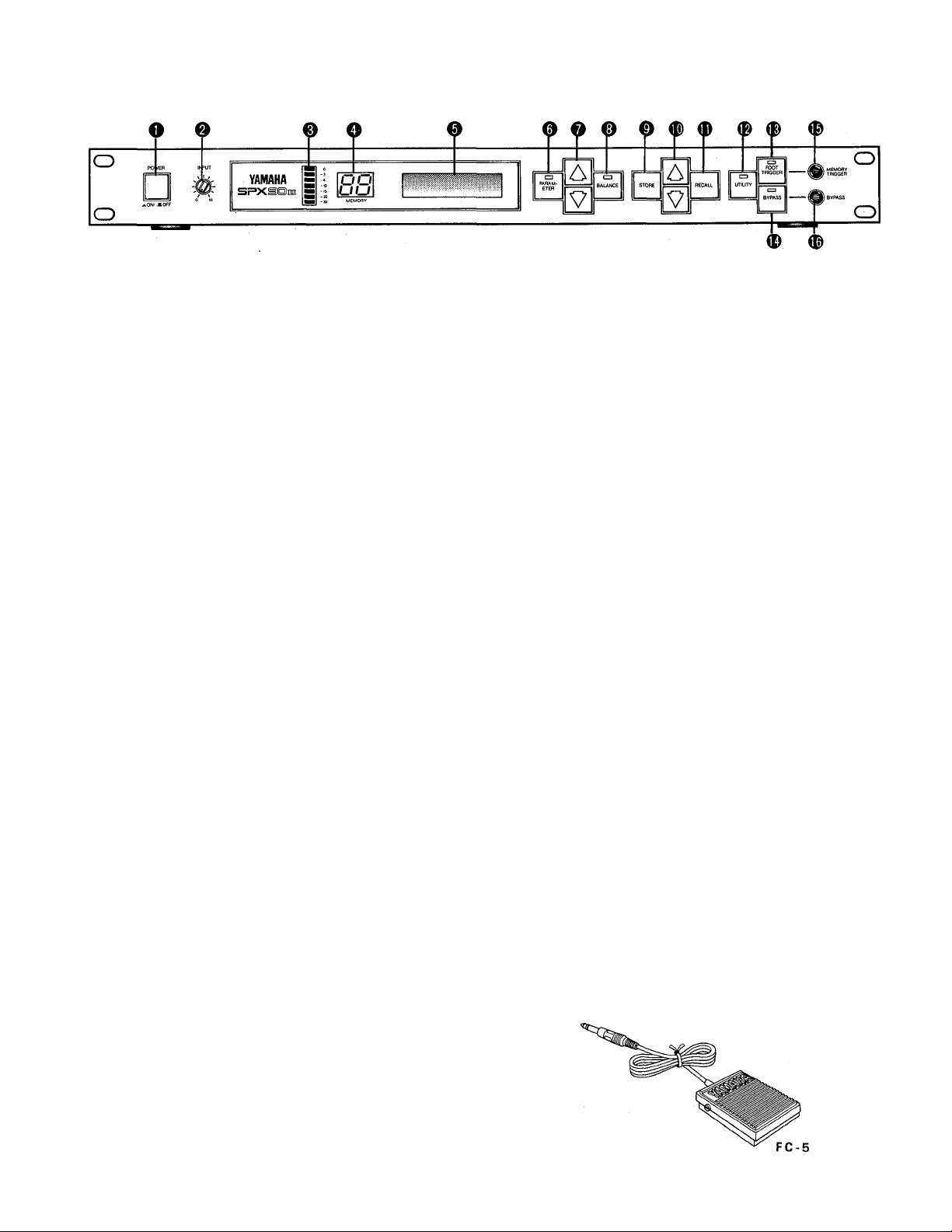
FRONT PANEL
O Power OIM/OFF Switch
When the power is turned ON, the program which
was selected immediately before the power was
turned OFF will be re-selected. Due to the safety
muting circuit, no sound will be produced by the
SPX90II for a few seconds after the power is
turned ON.
0 Input Level Control (0~10)
Regulates the level of the input signal. Set the
INPUT LEVEL control while watching the INPUT
LEVEL meter. The seven LED meter segments
should not all be continuously on when an input
signal is applied, as this will result in input amplifier
overload and distortion. When the INPUT LEVEL
control is set to "8" on the scale, the input/output
gain is 1 (unity). A setting of "10" increases gain
by about 10 dB.
0 Input Level Meter
This easy-to-read LED level meter is a visual aid
to setting appropriate input levels. Generally, the
best input level setting will produce continuous
lighting of the lower green LED segments, while
the upper red segments flash only occasionally.
O Memory Number LED
This LED display shows the number of the cur
rently selected program. Memory numbers 1
through 30 contain factory-preset effects (ROM).
Memory numbers 31 through 90 can be used to
store edited versions of the preset effects (RAM).
0
LCD Program and Parameter Indicator
This high-contrast Liquid Crystal Display indicates
the effect name and parameter data value.
0
Parameter Key
Selects successive effect parameters. Pressing this
key sequentially calls the programmable parame
ters within the currently selected effect program.
Once the desired parameter has been selected, the
PARAMETER INCREMENT/DECREMENT keys
are used to change the value of that parameter,
thereby modifying the effect. The parameters
available for each program are different: refer to
the parameter chart on page 24.
0
Parameter Increment/Decrement Keys
These keys are used to change the value of a se
lected parameter. Press the increment key (up
arrow) to increase the value, or the decrement key
(down arrovyj to decrease the value.
0 Balance/Output Level Key
Adjusts proportion of effect signal to direct signal.
Pressing this key alternately causes the current
balance and output level values to be displayed
on the LCD. The Parameter Increment/Decrement
keys are then used to adjust the displayed values.
0
Store Key
Stores any edited preset effect in a selected RAM
memory position (31 ~90).
® Memory Increment/Decrement Keys
These keys select any desired memory number to
call a specific program or store an edited program
in the user memory area. The selected memory
number is shown on the MEMORY NUMBER
display. When a new memory number is called,
the MEMORY number display will flash until either
the STORE or RECALL function is activated.
0 Recall Key
Press this key to recall the program that resides
in the selected memory number.
0 Utility Key
Multi-purpose key accesses MIDI control func
tions, facilitates program title editing and sets
footswitch memory control range. See pages 8
and 9 for details.
® Foot Trigger Key
When this key is pressed and its LED is ON, the
footswitch connected to the Memory/Trigger jack
functions as a foot trigger for the GATE and
FREEZE programs, rather than for memory se
lection.
0 Bypass Key
When this key is pressed, the effect signal is shut
off and only the direct signal will be output. Direct
signal level is affected by the IN PUT LEVEL control
setting.
0 Memory/Trigger Footswitch Jack
Facilitates remote memory selection via optional
footswitch. The range of memory locations to be
recalled by the footswitch can be set with a Utility
program. When the foot trigger function (above)
is ON, the footswitch connected to this jack acts
as a trigger footswitch rather than memory control.
Use of a Yamaha FC5 Foot Controller is recom
mended.
0 Bypass Footswitch Jack
Facilitates foot control of the BYPASS function
described above. A Yamaha FC-5 Foot Controller
is recommended.
Page 5
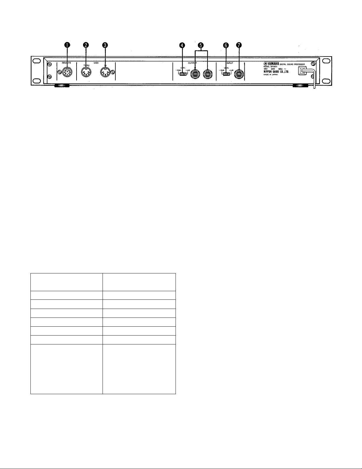
REAR PANEL
U.S & Canadaian models
Remote Control Connector
Permits remote access to SPX90II effect programs.
The optional remote control unit, model RC7,
permits direct access to programs 1 through 7 and
31 through 37, while all other preset programs may
be accessed sequentially.
This LED lights whenever
a remote control key is
pressed.
-Preset keys.
When this key is
pressed, the USER LED
will light and it becomes
possible to select user
programs 31 through 37.
USER LED ON
It is possible to call user
programs when this LED
is lighted.
USER LED OFF
— Preset programs —
1. REV 1 HALL
2. REV 2 ROOM
3. REV 2 VOCAL
4. REV 4 PLATE
5. EARLY REFLECTION 1
6. EARLY REFLECTION 2
7. DELAY L, R
1
- 34 - - 35 -
KEY ON
^ USER
YAMAHA
— User programs —
31. User program
32. User program
33. User program
34. User program
35. User program
36. User program
37. User program
i
30. PARAMETRIC EQ
(Programs 8 through 30
selected sequentially by
pressing OTHERS/ -37key)
o MIDI THRU Connector
Re-transmits MIDI data received at the MIDI IN
connector to subsequent MIDI instruments.
0 MIDI IN Connector
Permits SPX90II effect programs to be automat
ically selected via a MIDI signal. This connector
must be connected to the MIDI OUT connector
of the transmitting MIDI instrument via a standard
MIDI cable.
O Output Level Selector (-20 dB, -i-4 dB)
Facilitates SPX90II source/line level (sensitivity)
matching.
0
Output Jacks (L and R)
These are standard mono 1/4" phone jacks which
deliver the direct and effect signal to subsequent
mixing or amplification equipment. Since the
SPX90II offers stereo output, we recommend that
the output signal be fed in stereo to a stereo sound
system in order to take full advantage of the superb
stereo effects provided; Output impedance is 600
ohms.
0
Input Level Selector (-20 dB, h-4 dB)
Permits SPX90II source/line level (sensitivity)
matching.
O Input jack
This standard unbalanced mono 1 /4" phone jack
accepts the input signal to the SPX90II. Input
impedance is 10 k-ohms.
Page 6
BASIC OPERATIONS
Before actually selecting or editing programs on your SPX90II, make sure that all connections have been made
properly, and that the INPUT LEVEL switch, OUTPUT LEVEL switch, and INPUT LEVEL control have been properly
set according to the source signal and equipment to which the SPX90II signal will be fed.
/ PRESET PROGRAM SELECTION
Your SPX90II is equipped with a selection of 30
outstanding preset effect programs which are listed
in the ROM CONTENTS AND CONTROLABLE PA
RAMETERS on page 24. The preset (and user) pro
grams are selected as follows:
1. Use MEMORY INCREMENT/DECREMENT keys
to select desired memory number (remember, 1
through 30 are the presets).
2. Press RECALL key to call program in selected
memory number.
PGM currently in use
Ù
\MJ_M /
——blink-
L
/I
\ \\
Л
7 EDITING: CHANGING PARAMETERS
The SPX90II offers incredible sonic flexibility, as each
effect type comprises its own set of parameters (see
parameter chart on page 24). These parameters can
be adjusted to suit your tastes and the tonal charac
teristics of your musical equipment. We therfore re
commend that you examine each preset effect program,
and observe how these parameters affect the sound.
You will soon discover many new and exciting ap
plications for the SPX90H's preset effect programs.
1. Select and recall desired program as described
above.
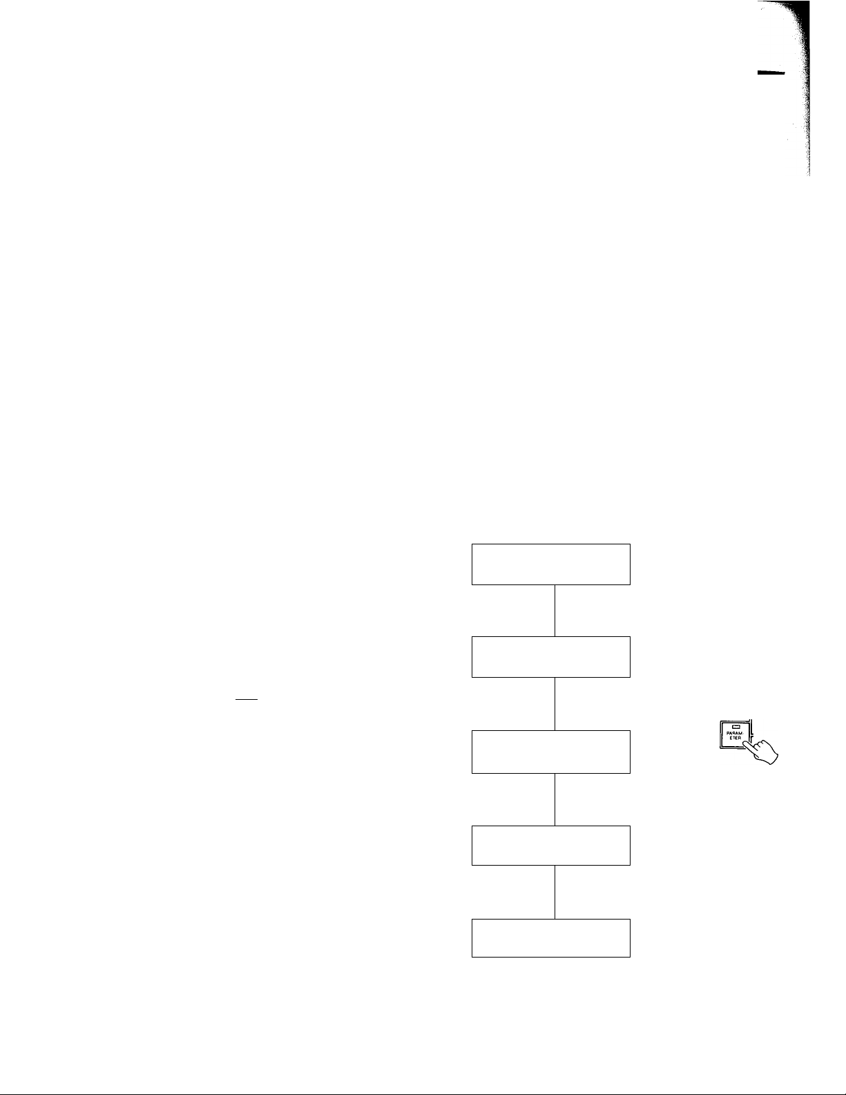
2. Press PARAMETER key to access the various pa
rameters available in the selected program. Each
time the PARAMETER key is pressed, the next
parameter in the list is called.
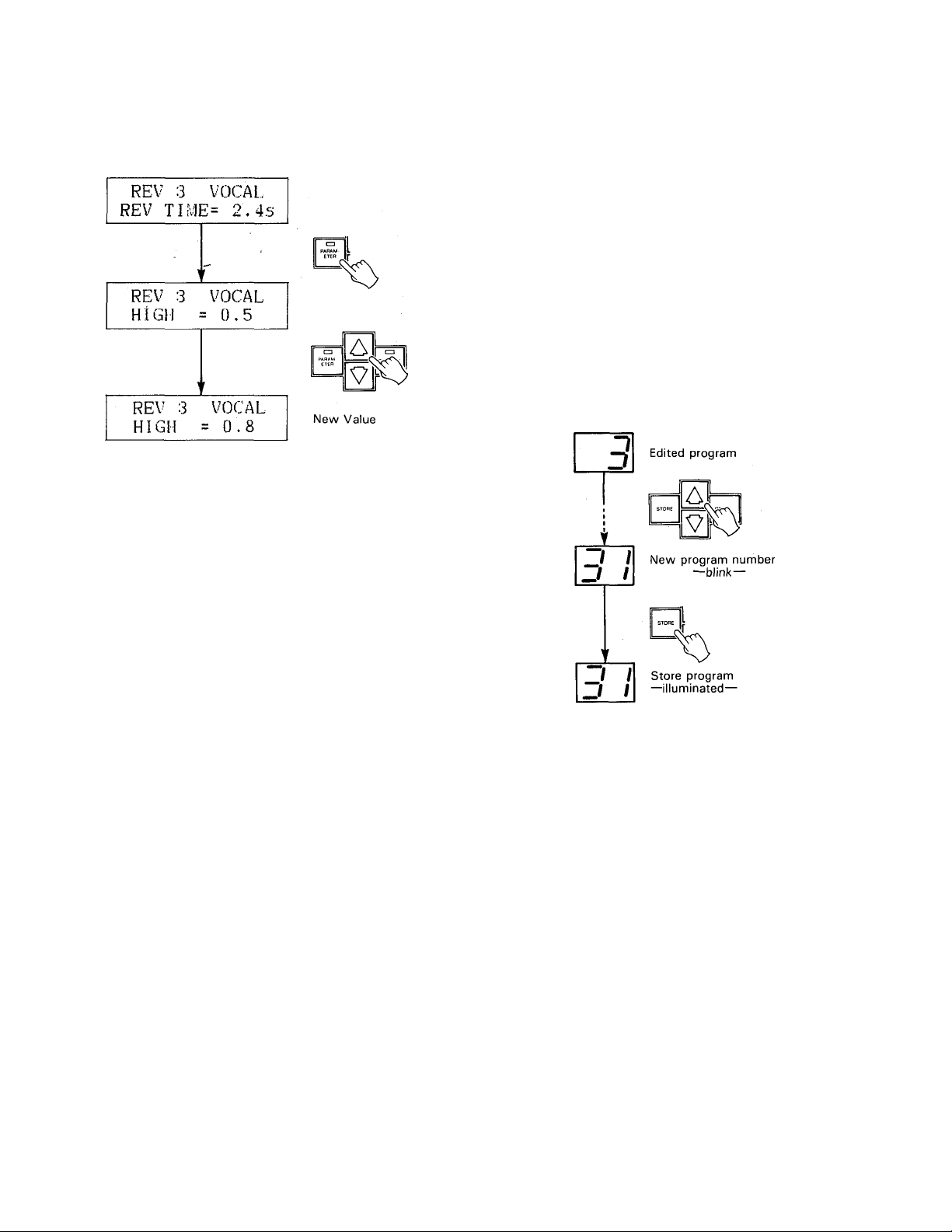
REV 3 VOCAL
REV TIME= 2.4s
д а
—blink—
3
111
I I l\
|j RECAU I
-illuminated—
3
NOTE: The same process is used to select user pro
grams (memory number 31 through 90) once
you have edited and stored your own programs
in user memory.
REV 3
HIGH
REV 3
VOCAL
= 0.5
VOCAL
DELAY = 45.0ms
'
REV 3
HPF
REV 3
LPF =8
VOCAL
80 Hz
VOCAL
.0 kHz
д а
Page 7
3. Use PARAMETER IIMCREMENT/DECREMENT
keys to set desired value of the selected parameter.
NOTE: A description of each parameter and its effect
will be given in the DESCRIPTION OF PRO
GRAMS AND PARAMETERS section, be
ginning on page 10.
STORE: SAVING EDITED PROGRAMS /
Once you've edited parameters on a preset program,
those changes will remain in effect only until you select
(RECALL) another program. The STORE function,
however, allows you to save the edited program in
any one of the user memory locations—from 31 to
90—from which it can then be recalled at any time.
1. Select and edit a program as described above.
2. Use the MEMORY INCREMENT/DECREMENT
keys to select a clear memory location between 31
and 90.
3. Press the STORE key.
The edited program has now been stored in the selected
user memory location. The stored program may now
be recalled at any time by following the normal program
selection procedure.
NOTE; If you attempt to store a program in one of the
read-only preset locations (1 through 30), the
SPX90II will display the "#1 ~#30 READ
ONLY" error message.
The SPX90II has an Edit Title Function, which
allows you to provide your own titles for edited
programs. (See the UTILITY function on page
8.)
Page 8
1
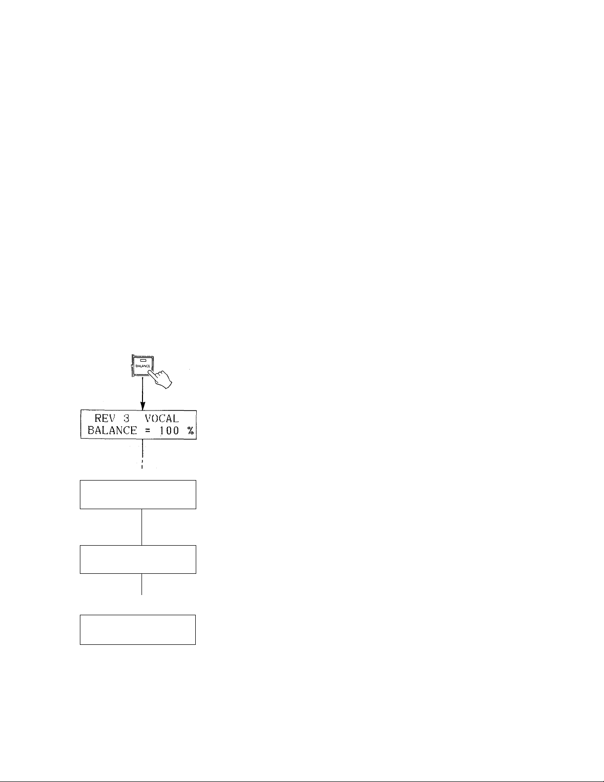
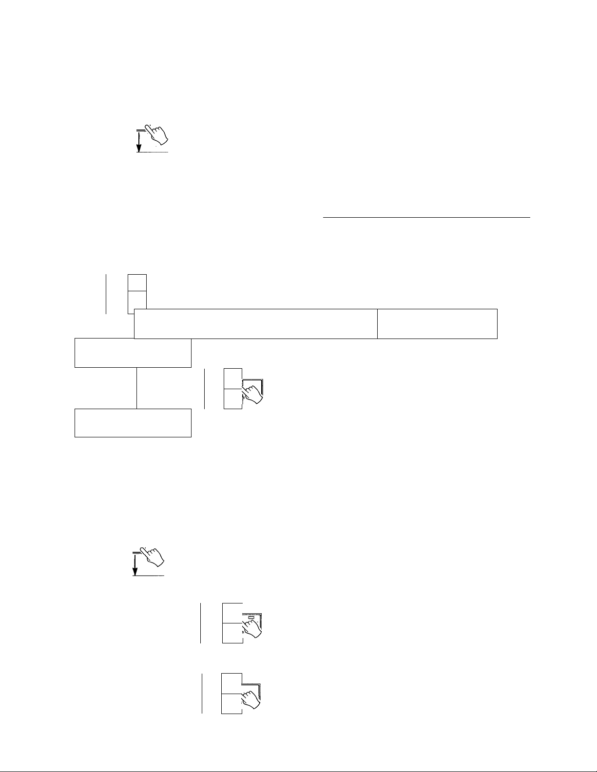
OUTPUT BALANCE AND LEVEL PRO
GRAMMING
The BALANCE key selects the BALANCE and OUT
PUT LEVEL functions for all programs.
1. Press the BALANCE key while any parameter is
selected. _ '
2. The first function called will be BALANCE. Adjust
the BALANCE of the effected and direct signal
between 0 and 100% using the PARAMETER
INCREMENT/DECREMENT keys.
* Balance = 100% : effect sound only.
Balance = 0% ; direct sound only.
3. Press the BALANCE key again to call the OUTPUT
LEVEL function. Adjust using the PARAMETER
INCREMENT/DECREMENT keys.
* OUT LVT = 100% : maximum output level.
OUT LVL = 0 % : no sound will be output.
/ BYPASS
When the BYPASS key is pressed and its LED lights,
the effect signal is defeated and only the direct input
signal is delivered via the OUTPUT jacks. The BAL
ANCE and OUTPUT LEVEL functions are also by
passed. The BYPASS function can also be activated
via a a footswitch connected to the BYPASS jack. A
normally-closed-type footswitch such as the Yamaha
FC-5 must be used.
REV 3
VOCAL
BALANCE = 50 7„
' <
REV 3
OUT LVL
REV 3
OUT LVL
VOCAL
= 100 7o
VOCAL
= 90 7o
a
A
Page 9

UTILITY FUNCTIONS
The UTILITY key provides access to four utility func
tions. These functions are selected in the following
sequence each time the UTILITY key is pressed:
Normal mode -EDIT TITLE - MIDI CONTROL
MIDI PROGRAM CHANGE - FOOTSWITCH ME
MORY RECALL Normal mode.
The UTILITY key L€D will light during selection of the
four utility functions, a-nd will go out when the normal
mode is returned to. When the UTILITY LED is ON,
the PARAMETER and MEMORY NUMBER
INCREMENT/DECREMENT keys will perform special
functions as described below, so normal parameter
and memory selection can not be performed until the
normal mode is selected.
EDIT TITLE
This function makes it possible to provide new titles
for programs which you have edited and stored in user
memory (31 through 90). When the EDIT TITLE
function is called, the lower line of the LCD will display
the "EDIT TITLE" function name, and the upper line
will display the title of the currently selected program.
The PARAMETER and BALANCE keys can then be
used to move the cursor left and right, respectively,
to select the character to be changed. Place the cursor
over a character, then use the PARAMETER
INCREMENT/DECREMENT keys to scroll through the
character list, stopping at the desired character. Move
the cursor to the next character location and repeat
this operation until the new title is complete. The
available characters are as follows:
0
#
G H 1
Y z
0 0
>
r
J
ZJ
'ir
/ \
t 7
JL' u
1
p q
•
“
+f
P
2 3
J K
a a
*
7
r
+ -
-
7
4
5 6
L
M N 0
b
C d e
S
t u
=
T
7
•b
V
-7 A
>
&
•Y -f
ir
7 8
u V
P
f
.
0 0
"J
9
R s T u
Q
h
g
W
X
X
"J X h
A
y
%
X
B c
i
Z
■t
n. B
k
7
-
D E
V W
1 m
[ ]
-
-
:h
7 /
3 7
F
X
n
<
[mbi FUNCTIONS
With the SPX90II it is possible to select specific pro
grams via external MIDI control. For example, you can
set the SPX90II so that when you select a specific
voice on your MIDI synthesizer, the most appropriate
effect program for that voice is selected automatically.
In this case, the SPX90II is detecting the MIDI Program
Change signal. For the following programs only, the
SPX90II also detects the MIDI Note ON/OFF signals:
* GATE programs (GATE ON/OFF).
* PITCH programs (set pitch).
* FREEZE programs (begin playback).
For MIDI program change operation, it is possible to
program four independent sets of program
change/memory number combinations. These are
referred to as "banks" in the SPX90II. For example,
you could program the four banks with different
combinations as shown in the chart below.
— Receive channel
BANK:A
pi_j _ 1
PGM 1 =MEM 1
PGM 2 =MEM 4
PGM 3=MEM 8 PGM 3 =MEMI6
PGMI28 = MEM40
Voice PGM
number
Memory number of SPX90
BANK;C
CH = 15
PGM 1 = MEM 90
PGM 2 = MEM 89
PGM 3 = MEM 88
PGMr28 = MEM40
* For bank D, the initial setting (program No. equals memory
No,) will be in effect upon power ON.
The second function accessed by the UTILITY key—-
MIDI CNTRL—permits BANK selection and setting
of the MIDI channel number on which MIDI program
change data for that BANK will be received. The third
function accessed by the UTILITY key—MIDI PGM
CHANGE—makes it possible to set the SPX memory
number which will be called when a specific MIDI
program change number is received.
BANK:B
CH- 2
PGM 1 =MEM 6
PGM 2 =MEM 7
PGM 128= MEM 1
BANK;D
CH=OMNI
PGM 1 =MEM 1
PGM 2 =MEM2
PGM 3 =MEM 3
PGM 128 = MEM 38
f
Page 10
MIDI Bank and Channel Programming
When this function is called, the LCD will appear as
follows:
MIDI CONTROL
BANK:x^ ch= xx
Use the PARAMETER INCREMENT/DECREMENT
keys to select the desired BANK, and the MEMORY
INCREMENT/DECREMENT keys to select the desired
MIDI channel number for that BANK. When "CH =
OMNI" is selected, reception will be carried out on
all 16 MIDI channels simultaneously. When CH =
OFF is selected, MIDI reception will be turned OFF.
a
A
PA RAM
ETER
'
MIDI CONTROL
BANK : A ch= XX
Selected bank
y
1 '
V
MIDI CONTROL
BANK : A ch= 1
Use the PARAMETER INCREMENT/DECREMENT
keys to set the MIDI program number (PGM), and the
MEMORY INCREMENT/DECREMENT keys to select
the SPX90II memory number (MEM) to be called
when that program number is received. For example,
if "PGM 12 = MEM4" isset, SPX90II memory number
4 will automatically be called whenever voice number
12 is selected on your MIDI synthesizer. The MIDI
program number range is from 1 to 128, while the
SPX90II memory number range is from 1 to 90.
/ FOOTSWITCH MEMORY RECALL RAN^
The SPX90II permits memory number selection via a
footswitch plugged into the front-panel
MEMORY/TRIGGER jack. The fourth function ac
cessed by the UTILITY key-FOOTSWITCH MEMORY
RECALL— permits setting the range of memory num
bers to be selected via the footswitch.
F.SW MEMORY RCL
RANGE 1 TO 30
If, for example, the RANGE is set to "1 TO 30" as
shown on the LCD above, each press on the footswitch
will successively call the next highest memory number:
1 2 ^ 3 .... 30 -> 1. Note that the sequence returns
to the first number in the range once the highest number
is passed. Reverse sequences can be programmed by
entering the highest number in the range before the
lowest.
Selected channel
Setting MIDI Program Number/SPX90 Memory
Number Combinations.
When this function is called by pressing the utility key
again, the LCD will appear as follows:
MIDI PGM CHANGE
PGMxxx = MEM XX
a
Al
ETER
V
MIDI PGM CHANGE
PGM 12 = MEM XX
A,
VI
MIDI PGM CHANGE
PGM 12 = MEM 4
F.SW MEMORY RCL
RANGE 34 TO 31
In this case the sequence is: 34 -> 33 ^ 32 -»• 31
34, etc.
Page 11
DESCRIPTION OF PROGRAMS AND PARAMETERS
The preset programs in the SPX90II fall into the following types: REV (Reverb), ER1 and ER2 (Early Reflections),
DELAY, ECHO, MOD (Modulation), GATE, PITCH, FREEZE, PAN, VIBRATO and PEQ (parametric equalizer). Each
of these program types has a specific selection of programmable parameters.
"Parameters" indicates the separate, individual functions that make up each effect. There are two types of parameters
in the SPX90II: "invisible" parameters (non-programmable, fixed-value parameters) and programmable parameters
(those you can edit, or modify).
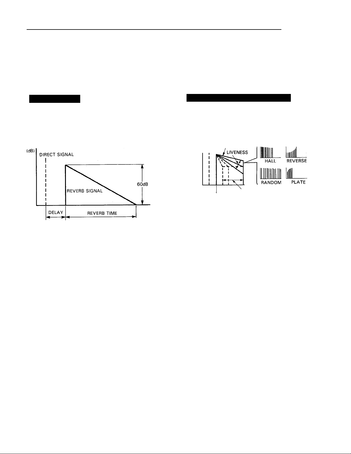
REV (REVERB)
Most commonly associated with musical "ambience,"
reverberation is a result of myriad reflected sound
waves within an acoustical environment, i.e. a concert
hall, auditorium, or soundstage. The SPX90II creates
extremely vibrant, natural sounding reverb.
■(TIME)
REVERBERATION TIME (R/T). Range: 0.3 ~99.0 sec
The length of the time it takes for the level of re
verberation at 1 kHz to decrease by 60 dB—virtually
to silence. In a live setting , this depends on several
factors: room size, room shape, type of reflective
surfaces, among others.
2.
HIGH (High Frequency Reverb Time Ratio).
Range: 0.1 ~ 1.0
Natural reverberation varies according to the fre
quency of the sound— the higher the frequency,
the more the sound tends to be absorbed by walls,
furnishings, and even air. This parameter permits
you to alter the reverberation time of the high fre
quencies in proportion to the mid-frequency reverb
time.
ER1 and ER2 (Early Reflections)
"Early Reflection" effects. ER1 has fewer reflections,
and is a LOW DENSITY early reflection effect, while
ER2 has more reflections, and is a HIGH DENSITY
early reflection effect.
DIRECT REFLECTIONS
(dB) SIGNAL
DELAY)
1. TYPE. Range: HALL, RANDOM. REVERSE,
PLATE
TYPE selects the pattern of the earliest reflections
of the reverb sound. All "Early Reflection" presets
are switchable between 4 different types. These
are HALL (a typical grouping of early reflections
that would occur in a performing environment like
a hall), RANDOM (an irregular series of reflections
that could not occur naturally), PLATE (a typical
grouping of early reflections that would occur in
a plate reverb unit), and REVERSE (a series of re
flections that increase in level, like the effect pro
duced by playing a recorded reverb/echo back
wards). See the E/R Mode chart on page 26.
2. ROOM SIZE. Range: 0.1 ~ 20.0
The ROOM SIZE parameter sets the time "gaps"
between the early reflections—directly propor
tionate to the size of the room. The effect of this
parameter also depends on which Early Reflection
mode has been selected. A Room Size Chart can
be found on page 27 in this manual.
EARLY
ROOM SIZE
^TYPE-
(TIME)
DELAY. Range: 0.1 ~ 1000.0 msec
3.
For a listener in a concert hall, there is a time delay
between the direct sound of the instrument, and
the first of the many reflected sounds that together
are known as reverberation. On the SPX90II, this
is known as the DELAY time.
HPF (High Pass Filter): Range. THRU, 32
4.
Hz ~ 1.0 kHz
Permits cutting the low frequency content of the
reverb signal bfelow the set frequency. When set
toTHRU, the HPF isOFF.
LPF (Low Pass Filter). Range: 1.0 kHz ~ 11
5.
kHz, THRU
Permits cutting the high frequency content of the
reverb signal above the set frequency. When set
toTHRU, the LPF is OFF.
3. LIVENESS. Range: 0 ~10
Refers to the rate at which the reflected sounds fade.
Set this parameter at zero to simulate an acoustically
"dead" room, with absorbent surfaces to "soak up"
the reflected sounds. As you increase the setting,
the room appears to contain more "live" surfaces,
with the reflected sounds fading more slowly, as
they reflect from wall to wall, until at the maximum
setting the effect is of an intensely reflective envi
ronment containing many highly polished surfaces
(tiles, glass, etc).
4. DELAY. Range: 0.1 ~ 1800.0 msec
The time delay between the direct sound of the
instrument and the first reflection to reach the
listener's ear.
5. LPF. Range: 1.0 kHz ~ 11 kHz, THRU
Same function as the LPF parameter of the REV
program.
10
Page 12
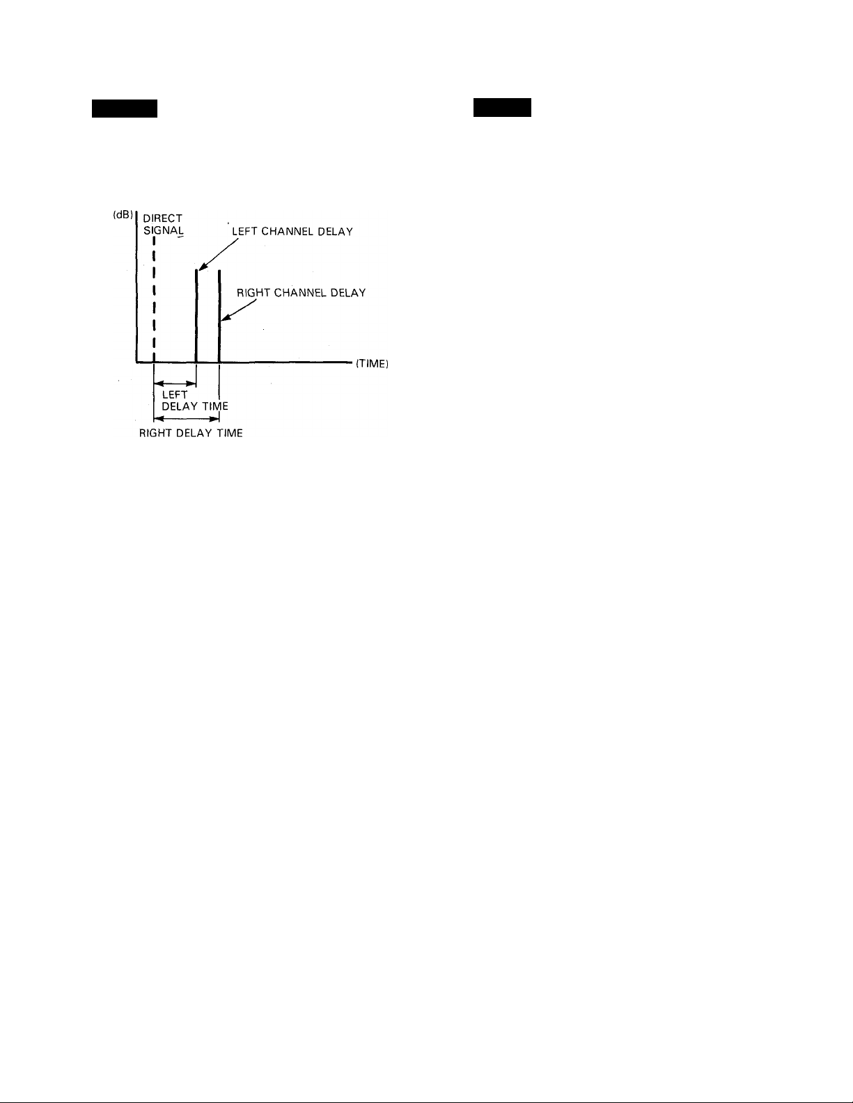
DELAY
ECHO
This effect, commonly used in contemporary re
cordings, produces independently variable left-and
right-channel signal delays. The result is an intriguing
"doubled" sound.
1. LEFT CHANNEL DELAY TIME. Range: 0.1 ~
2000.0 msec
Permits highly accurate setting of the left channel
delay following the direct sound.
2. LEFT CHANNEL FEEDBACK GAIN. Range:
-99% ~ -t-99%
Sets the amount of delay signal fed back to the input
circuitry. The higher the feedback gain setting, the
greater the number of delay repeats produced. A
negative value setting produces out of phase
feedback.
3. RIGHT CHANNEL DELAY TIME. Range: 0.1
~ 2000.0 msec
Sets the delay time of the right channel.
4. RIGHT CHANNEL FEEDBACK GAIN. Range:
-99% ~ -t-99%
Permits setting the feedback gain setting of the right
channel delay.
5. HIGH (FEEDBACK HIGH).Range: 0.1 ~ 1.0
Controls feedback of the high-frequency range.
The high frequency feedback is reduced as the value
of this parameter is reduced.
Similar to Delay, Echo brings added dimension and
force to both instrumental and vocal music. While
Reverberation recreates an abundance of partial sound
reflections, and Delay produces a limited number of
signal repetitions. Echo can produce limitless signal
repetitions.
(dB)
DIRECT SIGNAL
L R
-(TIME)
LEFT
DELAY TIME
RIGHT DELAY TIME
1. LEFT CHANNEL DELAY TIME. Range: 0.1 ~
1000.0 msec
After this delay time has elapsed, the first echo
will appear. Subsequent echoes will appear at the
same time interval, the number of echoes depending
on how the Feedback Gain parameter is set.
2. LEFT CHANNEL FEEDBACK GAIN. Range:
-99% ~ -f99%
This parameter permits adjustment of the number
of echoes that follow the direct signal, from zero
to a virtually infinite repeat at the maximum setting.
The overall decay time of the effect is proportionate
to the Feedback Gain setting.
3. RIGHT CHANNEL DELAY TIME. Range: 0.1
~ 1000.0 msec
4. RIGHT CHANNEL FEEDBACK GAIN. Range:
-99% ~ +99%
Parameter 3 and 4 have the same function as those
of 1 and 2 but the signal will be produced from the
right output.
5. HIGH (FEEDBACK HIGH). Range: 0.1 ~ 1.0
Determines the portion of high frequency feedback.
The lower the value, the less high frequency is
produced.
11
Page 13

MODULATION
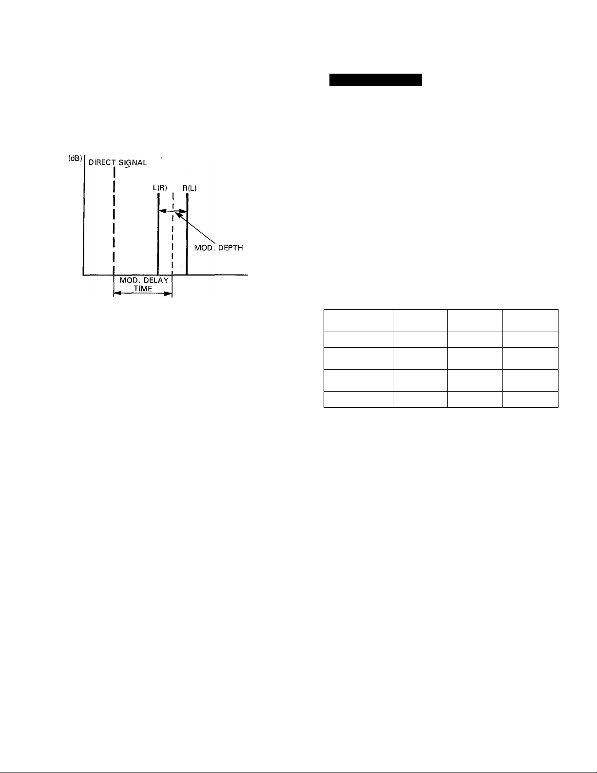
STEREO FLANGE
A combination of Delay and LFO (Low Frequency
Oscillation) modulation, the popular Flanging effect
can dramatically thicken the sound of keyboard in
struments, or prodpce thé "aircraft" sound popular
among guitarists. Basically, a short delay time is varied
with LFO modulation so that the delayed signal moves
in relation to the direct signal. The resultant variations
in pitch and stereo imaging are known as "flanging".
(dB)
DIRECT
SIGNAL
MOD. DELAY TIME
MOD. DEPTH
UR)/ R(L)
•(TIME)
1. MOD FREQ. Range: 0.1 ~ 40.0 Hz
Sets the speed of modulation, and hence the rate
at which the effect varies.
2. MOD DEPTH. Range: 0 ~ 100%
This sets the amount of delay time variation, thus
adjusting the "depth" of the effect. At the maximum
setting, the delay time is varied by -t-/-4 msec.
3. MOD DELAY TIME. Range: 0.1-100.0 msec
This sets the basic delay time from the initial direct
sound to the flange effect. When set to lower than
1 msec, more high-frequency variation is produced,
while a setting higher than 3 msec will create more
low-frequency variation.
CHORUS
With the Chorus effect, a violin, keyboard, or guitar
can sound like an entire ensemble. Chorusing splits
the incoming signal into three signals placed at the
center, left, and right in the stereo image. Each signal
is delayed slightly, and then its delay time and level
are modulated by the LFO (Low Frequency Oscillator).
(dB)
DIRECT SIGNAL
AMPLITUDE
MODULATION DEPTH
•(TIME)
DELAY MODULATION DEPTH
1. MOD FREQ. Range: 0.1 - 40.0 Hz
Sets the delay time modulation speed (frequency).
2. DELAY MODULATION DEPTH. Range: 0 -
100%
This sets the amount by which the delay time of
one delay signal is varied in relation to the other.
At the maximum setting, the delay time is varied
by + /-4 msec.
3. AMPLITUDE MODULATION DEPTH. Range:
0 - 100%
This sets the amount by which the amplitude (level)
of the input signal is varied.
4. F.B. GAIN. Range: 0 - 99%
Sets the amount of flange signal which is fed back
into the circuit for further modulation. This controls
the complexity of the effect, its "strength," and its
overall decay time.
12
Page 14
STEREO PHASING
PITCH CHANGE
The SPX90II can produce a wide range of Phasing
effects from a barely perceptible shift to a rapid pul
sation. Phasing lends an animated quality to musical
instrument and vocal recordings:
(TIME)
This effect has the same parameters as STEREO
FLANGE, except that the DELAY TIME range is from
0.1 to 8.0 msec and that it omits F.B. Gain.
TREMOLO
The TREMOLO effect operates in the same way as the
CHORUS effect, except that modulation is deeper and
the delay variation is greater. Refer to STEREO
FLANGE for the description of the parameters.
-SYMPHONIC
The programmable parameters for this preset are
identical to those for the Stereo Flange preset, omitting
F.B. GAIN and MOD DELAY TIME.
This program is used to change the pitch of an input
signal. Pitch can be changed in semitone increments
over a plus/minus one-octave range. Fine adjustment
of pitch in one-cent (1/100th of a semitone)
increments/decrements is also possible. Pitch change
programs B and C permit setting two different pitches.
This makes it possible to produce a detune type effect
(i.e. when you play a note, the SPX90II outputs two
additional notes), or, if only a slight pitch difference
is used, chorus-type effects are created. Pitch change
programs A and D permit the application of feedback
so that an echo that changes in pitch with each repeat
can be produced. Programs A and D further permit
pitch control via the MIDI IN connector. Any MIDI
synthesizer, such as the Yamaha DX7, can be used to
alter the pitch setting of the program by simply playing
the appropriate note on the synthesizer keyboard.
PROGRAM
PITCH CHANGE A
PITCH CHANGE B
PITCH CHANGE C '
PITCH CHANGE D 1 TONE
PITCH CHANGE
1 TONE
2 TONES
(CENTER)
2 TONES
(1 EACH IN
L & R CH.)
FEEDBACK
YES
NO
NO
YES YES
MIDI PITCH
CONTROL
YES
NO
NO
1. PITCH. Range: -12 ~ +12
Sets the degree of pitch change in semitone steps.
+ 12 corresponds to an output pitch one octave
higher than the input pitch, and -12 produces an
output pitch one octave lower than the input pitch.
2. FINE. Range; -100 ~ +100
Adjusts pitch in one-cent increments or decrements.
3. DELAY Range: 0.1 ~ 1800.0 msec (A, B, D),
0.1 ~ 900.0 msec (C)
Sets the delay between the direct (input signal)
and the pitch-changed output signal.
13
4. F.B.GAIN. Range: 0 ~ 99% (A,D only)
The higher this setting, the more echo repeats are
produced (each changed in pitch from the previous
repteat).
5. BASE KEY. Range: OFF, Cl ~ C6 (A. D only)
This parameter sets the "BASE KEY" for an external
MIDI synthesizer used to control the pitch variation
Page 15

of the PITCH CHANGE program. For example, if BASE
KEY = C4, then pressing the C3 key on the synthesizer
keyboard will set the pitch change value to -12 (one
octave down). Pressing D4 on the keyboard would
produce a pitch increase of one tone (+2). If a key
more than one octave higher or lower than the BASE
KEY is pressed, the resultant pitch change setting will
still be within the -M2 to -12 range, as shown in the
following illustration. If the BASE KEY setting is OFF,
pitch can not be controlled via the MIDI IN terminal.
+ 3
+ I
+ 10 I
+ 8
+ 6
+ 3
I
- 2
- 4
- 6
- 9
_ I )
- 2
F 5
E 5
D 5
C 5
B 4
G 4
F 4
E 4
D 4
C 4
B 3
A 3
G 3
F 3
E 3
D 3
0 3
B 2
A 2
PITCH
+ 5
+ 4
+ 2 -
+ 12 -
+ I I
+ 9
+ 7
+ 5
+ 4
+ 2
0
- I
- 3
- 5
- 7
- 8
- !0
- 12 -
- I -
- 3
+ 1 - + 12 range is
repeated
Pitch can be changed
over a ± 12 range with
the BASE KEY in
the center.
- 1 — 12 range is
repeated
FREEZE
The FREEZE programs permit "recording" up to a
2000-millisecond signal in the SPX90II memory, and
playing it back as required. The FREEZE programs have
two basic steps: RECORDand PLAY. With the FREEZE
A program, it is possible to program a specific segment
of the recorded 2000-millisecond signal to be replayed
by programming the START and END points.
The FREEZE B program does not permit programming
START and END points, but the pitch of the recorded
signal can be ahanged for playback.
1. REC. MODE Selection. Range: Manual, Auto
Press the Parameter key and select the Manual mode
with the Parameter Increment key or AUTO Mode
by pressing the Parameter Decrement key. In the
MANUAL mode, press the Parameter Increment
key to begin recording, while in the AUTO mode
recording begins automatically when the SPX90II
detects an input signal.
2. TRIGGER DELAY. Range: -2000 ~ 2000msec.
This parameter determines the actual point at which
recording begins in relation to the trigger signal.
IfTRG DLYissetatO, recording begins immediately
when the FREEZE function is triggered. If a negative
TRG DLY value is set the input signal is delayed
so that in effect recording begins before the function
is triggered.
Trigger
Input Signal-
-Time
Note:
Depending on the input source, the sound output
may slightly be off from the specified pitch.
TRG. DLY
- 2000.0
1000.0
400.0
2000.0msec ,
M
------------------
Recorded range]
2000.0msec
------1-----
400.0msec—
H
, 2000.0msec
U
-------------------
-------------M—-------------
2000.0msec
H
-♦H
3. RECORDING
After the desired MODE has been set, press the
PARAMETER key and the LCD will display the
"RECORD" message. Then, enter the standby mode
by pressing the PARAMETER DECREMENT key.
The LCD will display the "REC READY" message.
14
Page 16
TRIGGERING
• MANUAL Mode
To actually begin recording if the MANUAL mode
has been selected, press the PARAMETER IN
CREMENT key. The SPX90II will record for 2000
milliseconds. Also the optional foot switch FC-5
can be used. Connect the FC-5 to the
MEMORY/TRIGGER Foot Switch jack and press
the FOOT TRIGGER key . Then the FC-5 works
as the trigger switch when it is pressed.
• AUTO Mode
If the AUTO mode has been selected, the
SPX90II will automatically begin recording when
an input signal of sufficient level is detected. The
LCD displays "TRIGGER!" when the freeze function
is triggered. When the recording begins the LCD
displays The freeze (recording) ends auto
matically after 2000msec and the display says "OK".
4. OVERDUB Recording
To "overdub," or record new material without
erasing the previously recorded material, use the
following procedure.
FREEZE A
REC. READY
-MANUAL Mode only-
Al
V
FREEZE A
TRIGGER!
FREEZE A
1. Press the PARAMETER key until the OVERDUB
display appears.
2. Press the PARAMETER DECREMENT key. This
sets the record ready status, and recording will begin
as soon as a trigger signal is received.
• FREEZE operation
FREEZE A
REC M0DE= xxxxxx
CD
A
PARAM
ETER
'
1701717717 A
REC M0DE= MANUAL
-or AUTO
1
FREEZE A
RECORD
FREEZE A
OK
PLAY
To begin recording again, press
the parameter decrement key to enter
the Rec Ready Mode.
15
C3
A
ETER
''
Page 17

5. PLAYBACK
To play back the recorded material, press the PA
RAMETER key to enter the playback standby mode.
The LCD will display the "PLAY" message. To
actually play the recording, press the PARAMETER
INCREMENT/DECREMENT key. The recorded
material will be played each time the PARAMETER
INCREMENT/DECREMENT key is pressed.
FREEZE A
PLAY
To program a specific segment of the recording to
be played back in the FREEZE A program, set the
START and END parameters to appropriate values
(0~2000.0). The example below depicts how the
START and END parameters affect output.
START/END POINTS
— 2000.0msec—
C
GOOD LUCK
ST/
2t
!kRT Er
OO.Omsec
4D
PLAYBACK SIGNAL
"GOOD LUCK"
Another way to trigger playback is to use the Input
Trigger Parameter. Select the Input trigger Parameter
and press the Parameter Increment key to enter the
standby mode. Playback will be automatically triggered
when the input signal exceeds nominal level.
The FREEZE B program PITCH and FINE parameters
function identically to those in the PITCH CHANGE
program to change the pitch of the playback signal.
Playback start and stop can be triggered by the PA
RAMETER INCREMENT/DECREMENT keys, foot
switch or via a MIDI keyboard connected to the MIDI
IN connector. With the FREEZE B program, playing a
key on the MIDI keyboard produces the corresponding
pitch change in the playback output, and triggers
playback.
6. TRIGGER MASK (FREEZE A). Range: 10-2000.0 ms.
This parameter makes it possible to disable playback
re-triggering for a specified time (10-2,000 msec).
For example, if you wish to prevent re-triggering for
the duration of the entire sample or a portion of the
sample, set the TRIGGER MASK parameter for the
appropriate length of time. Once playback has been
triggered, it can only be triggered again after the set
TRIGGER MASK time has elapsed.
GOOD LUCK
1
C
GOOD LUCK
GOOD LUCK
1 1 '
START END
GOOD LUCK
II
END START
START Er
I
START Ergo
slD
"OOD LUCK"
"LUCK"
"OD LU"
"LUCK GOOD”
Playback can also be triggered by a footswitch
connected to the front-panel MEMORY/FOOT
TRIGGER jack when the FOOT TRIGGER key is
pressed and its LED is ON. A MIDI keyboard
connected to the MIDI IN terminal can also be used
to trigger playback—simply play a note on the
keyboard.
16
Page 18
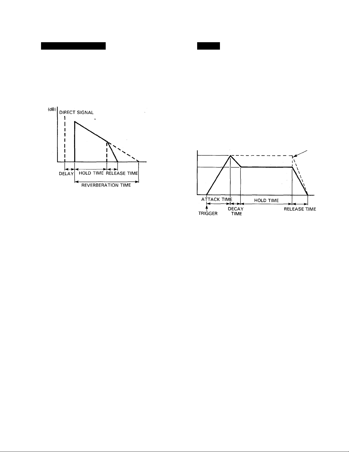
REVERB and GATE GATE
This program feeds the reverb signal through a gate
circuit, making it possible to output only a segment
of a longer reverb sound. Parameters provided for the
reverb portion of the signal are REV TIME, HIGH,
DELAY, HPF and LPF, while parameters for the gate
portion are HOLD TIME, RELEASE TIME, and MIDI
TRIGGER. '
-(TIME)
1. REVERB TIME (R/T). Range: 0.3 ~ 99.0 sec
2. HIGH (High Frequency Reverb Time Ratio).
Range: 0.1 ~ 1.0
3. DELAY. Range: 0.1 ~ 1000.0 msec
4. HPF (High Pass Filter). Range: 32 Hz ~ 1.0
kHz, THRU
5. LPF (Low Pass Filter). Range: 1.0 kHz ~ 11
kHz, THRU
All these parameters have the same function as
those of the REV programs. See page 10 for details.
6. TRIGGER LEVEL. Range: 0 ~ 100%
Determines the strength (amplitude) of the input
signal required to trigger opening of the gate. At
100%, only extremely high-level input signals will
trigger the gate, while at 0% even this slightest input
signal will trigger the gate.
7. HOLD TIME. Range: 1 ~ 30,000 msec
This parameter sets the amount of time the gate is
"open," allowing the reverb sound to come through.
8. RELEASE TIME. Range: 5 ~ 32,000 msec
This parameter determines the time it takes for the
gate to close completely after the HOLD TIME.
9. MIDI TRIGGER. Range: ON, OFF
When ON, a KEY ON signal from an external MIDI
keyboard can be used to trigger the R & G effect.
ADR-NOISE GATE
This program uses a gate circuit to pass or shut off the
input signal in a number of ways. It can be used to
pass just a short segment of a longer input signal,or
it can be used to pass only signals that exceed a specific
level (noise-gate type operation). It is also possible
to achieve reverse gate effects in which the gain in
creases gradually after the gate is triggered. In addition
to signal-level triggering, it is also possible to trigger
the gate via a footswitch connected to the front-panel
MEMORY TRIGGER jack when the FOOT TRIGGER
key LED is ON.
LEVEL = 100%
DECAY
LEVEL
1.
TRIGGER LEVEL. Range: 1 ~ 100%
Determines the strength (amplitude) of the input
signal required to trigger opening of the gate. At
100%, only extremely high level input signals will
trigger the gate, while at 0% even the slightest input
signal will trigger the gate.
2. TRIGGER DELAY. Range: -100
-----------
Produces a delay between the time at which the
gate is triggered and that at which it actually opens.
If a minus value is programmed, the input signal
itself is delayed so that, effectively, the gate opens
before the signal appears.
3. TRIGGER MASK. Range: 5 ~ 32,000 msec
This parameter makes it impossible to re-trigger the
gate function until the programmed time has
elapsed.
4. ATTACK TIME. Range: 5 msec ~ 32,000 msec
Determines how long it takes for the gate to open
fully from the time it begins to open,
5. DECAY TIME. Range: 5 msec ~ 32,000 msec
Determines the length of time it takes for the gate
to fall to DECAY LEVEL after it is fully open.
-(TIME)
100 msec
17
Page 19

6. DECAY LEVEL. Range: 0 ~ 100%
Determines the level at which the gate remains open
for the HOLD TIME. The lowerthe value, the lower
the HOLD gate level.
7. HOLD TIME. Range: 1 msec ~ 30,000 msec
Determines how long the gate stays open, allowing
the input signal to pass.
RELEASE TIME. Range: 5 msec ~ 32,000
8.
msec
Determines how long it takes for the gate to close
fully from the time it begins to close.
9. MIDI TRIGGER. Range: ON, OFF
When ON, a KEY ON signal from an external MIDI
keyboard can be used to trigger the gate.
COMPRESSOR
The COMPRESSOR effect reduces the level of the
attack portion of a music signal and keeps overall signal
level within narrow limits.
1. TRIGGER LEVEL. Range: 1 ~ 100%
Determines the strength of the attack signal required
to trigger the compressor effect.
2. TRIGGER DELAY. Range: -100 ~ 100 msec
Produces a delay between the time at which the
effect is triggered and that at which the compression
actually begins. If a negative value is programmed,
the input signal is delayed so that effectively, the
compression begins before the signal appears.
TRIGGER MASK. Range: 5 ~ 32,000 msec
This parameter makes it impossible to re-trigger the
compressor function until the programmed time
has elapsed.
4. ATTACK TIME. Range: 5 msec ~ 32,000 msec
Determines how long it takes until the HOLD level
(below) is reached after the effect is triggered.
HOLD TIME. Range: 1 msec ~ 30,000 msec
Determines how long the maximum compression
effect is maintained after the ATTACK TIME has
elapsed.
HOLD LEVEL. Range: 0 ~ 100%
6.
Determines the actual level to which all input signals
will be compressed during the HOLD TIME. The
smaller the value, the lower the level of the output
signal.
7. RELEASE TIME. Range: 5 msec ~ 32,000
msec
Determines how long it takes to return to normal
level once the HOLD TIME has elapsed.
8. MIDI TRIGGER. Range: ON, OFF
When ON. a KEY ON signal from an external MIDI
keyboard can be used to trigger the compressor
effect.
18
Page 20

PAN-
TRIGGERED PAN
This program automatically pans the sound image
between left and right in the stereo sound field. Pan
direction, speed, and phase can be programmed.
1. PAN SPEED. Range: 0.1
Sets the speed of pan.
2. DIRECTION. Range: L -> R, L
Determines the direction of pan.
3. DEPTH. Range: 0 -100%
Sets the degree of level variation. The higher the
value, the stronger the pan effect.
40.0 Hz
R. L-
In this program the pan effect is triggered by the input
signal or footswitch.
1. TRIGGER LEVEL. Range: 1 - 100%
Determines the strength of the attack signal required
to trigger the pan effect. The higher the value, the
higher the input signal level required to trigger the
effect.
2. TRIGGER DELAY. Range: -100 - 100 msec
Produces a delay between the time at which the
effect is triggered and that at which the pan effect
actually begins. If a negative value is programmed,
the input signal is delayed so that effectively,the
pan effect begins before the signal appears.
3. TRIGGER MASK. Range: 5 - 32,000 msec
This parameter makes it impossible to re-trigger the
pan function until the programmed time has
elapsed.
4. ATTACK TIME. Range; 5 msec - 32,000 msec
Determines how quickly or slowly the pan effect
reaches maximum depth after it is triggered.
5. PANNING TIME. Range: 5 msec - 32,000
msec
Determines how long the maximum-depth pan
effect remains active.
6. RELEASE TIME. Range: 5 msec - 32,000
msec
Determines how long it takes for the pan effect to
fade out after the PANNING TIME has elapsed.
7. DIRECTION. Range: L -R, L ^R
Sets the direction of pan.
8. LPF. Range: 1.0 kHz - 11 kHz, THRU
Determines the cutoff frequency of the low-pass
filter.
9. DELAY. Range: 0.1 - 1800.0 msec
Sets the delay time of equalized signal following
the direct signal.
NOTE: To use footswitch FC-5, connect the FC-5
to the MEMORY/TRIGGER FOOT Switch
jack and press the Foot Trigger key.
19
Page 21
DELAY VIBRATO
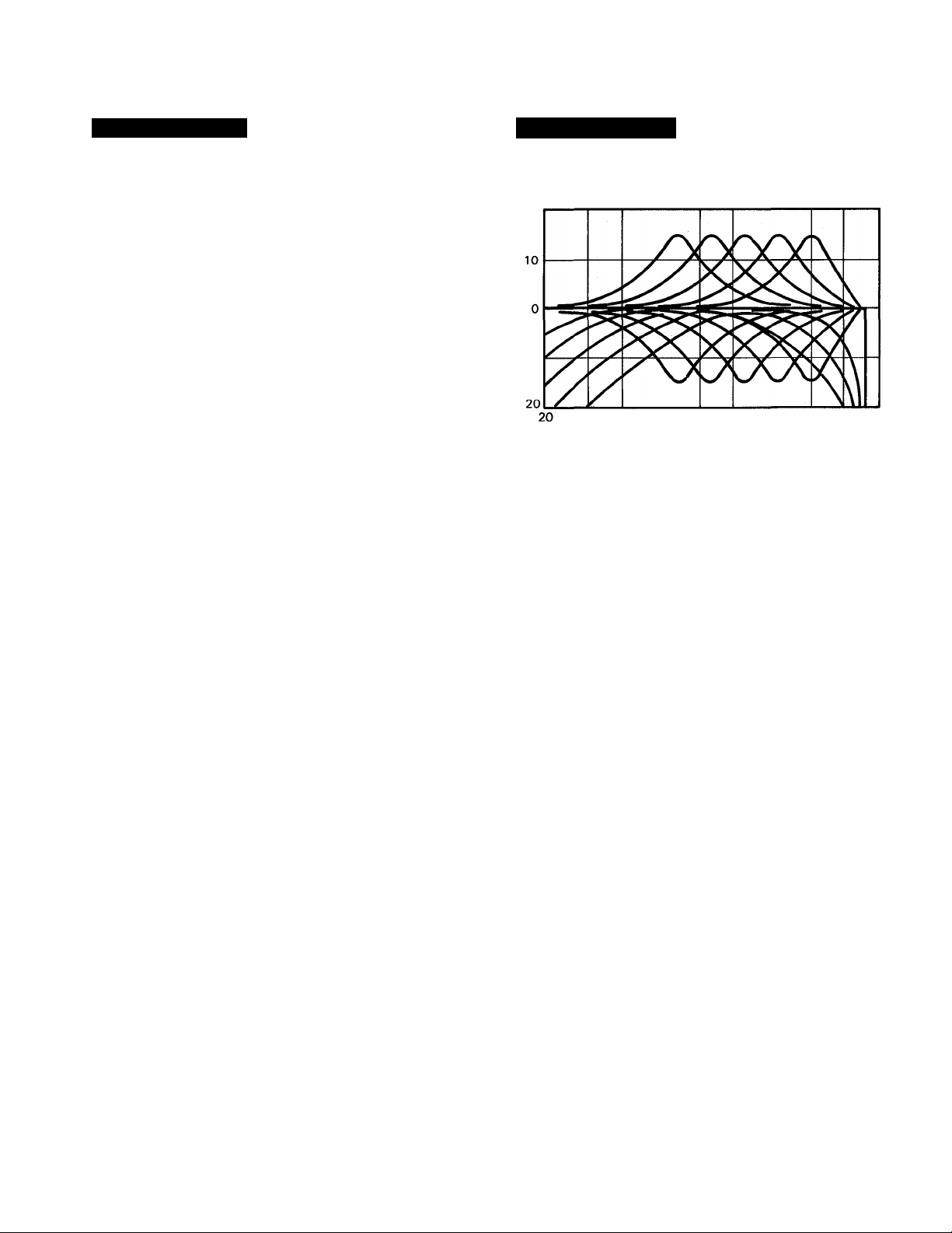
PARAMETRIC EQ
This program makes it possible to add delay vibrato
effects to virtually any instrument or sound. When the
input signal exceeds a programmed trigger level, the
vibrato effect is cancelled and then gradually builds
up to the programmed depth.
1. TRIGGER LEVEL. Range: 1 ~ 100%
Determines the input signal level at which the vi
brato effect is cancelled and begins to build up
again.
2. VIBRATO DELAY. Range: 1 ~ 30,000 msec
Determines how long the vibrato effect is cancelled
once triggered.
3. VIBRATO RISE TIME. Range: 5 msec ~ 32,000
msec
Determines how long it takes for the vibrato effect
to reach maximum depth after the VIBRATO DELAY
time has elapsed.
4. VIBRATO FREQUENCY. Range: 0.1 ~ 20.0
Hz
This parameter sets the frequency (speed) of the
vibrato effect.
5. VIBRATO DEPTH. Range: 0 -100%
Sets the depth (strength) of the vibrato effect.
6. MIDI TRIGGER. Range: ON, OFF
When ON, a KEY ON signal from an external MIDI
keyboard can be used to trigger the vibrato effect.
This program permits variation of the input signal
frequency response over an extremely broad range.
(dB) 20
- 10
50 100 500 Ik 5K IK 10K
(Hz)
1. HPF. Range: THRU, 32 Hz ~ 1.0 kHz
This sets the cutoff frequency of the high-pass filter.
Frequencies below the set frequency are rolled off
at a rate of 6 dB/octave. When set to THRU, the
HPF is OFF.
2. MID FRO. Range: 315 Hz - 4.0 kHz
Determines the center frequency of the midrange
equalization band. The midrange frequency can
be set in 1/6 octave increments.
3. MID GAIN. Range:-15 - +15 dB
Determines the amout of boost or cut applied to
the midrange equalization band.
4. MID Q. Range: 0.5 ~ 5.0
Sets the "Q" (Quality factor = bandwidth) of the
midrange EQ band. The higher the value, the
narrower the bandwidth.
20
5. HI FRO. Range: 800 Hz ~ 8.0 kHz
Determines the center frequency of the high-fre
quency equalization band.
6. HI GAIN. Range: -15 ~ +15 dB
Determines the amount of boost or cut applied to
the high-frequency equalization band.
7. HI Q. Range: 0.5 ~ 5.0
Sets the "Q" (Quality factor = bandwidth) of the
high EQ band. The higher the value, the narrower
the bandwidth.
8. LPF. Range: 1.0 kHz ~ 11 kHz, THRU
Deterrriines the cutoff frequency of the low-pass
filter.
9. DELAY. Range: 0.1 ~ 1800.0 msec
Sets the delay time of equalized signal following
the direct signal.
Page 22

SAMPLE APPLICATIONS
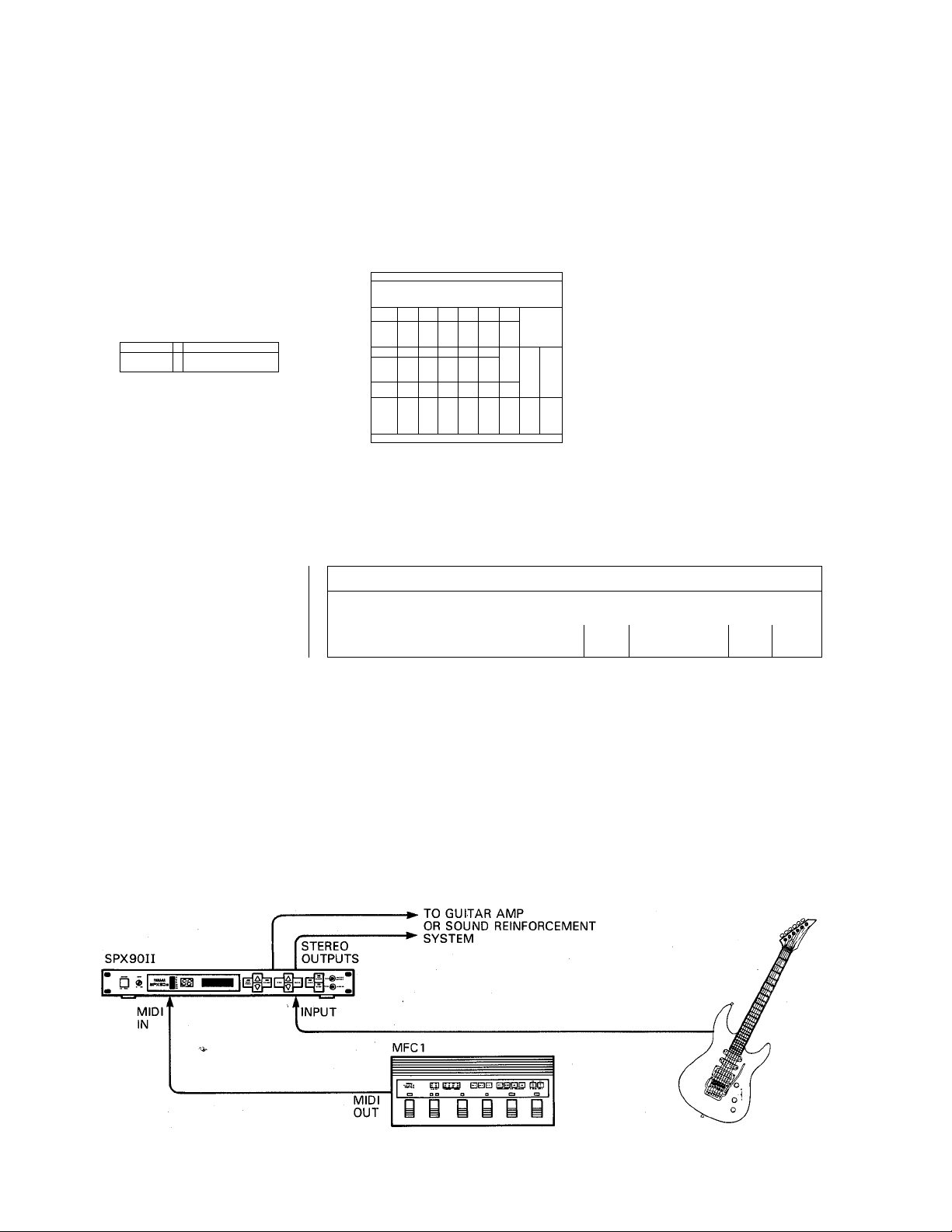
MIDI KEYBOARD PERFORMANCE SYSTEM
In this system the SPX90II is connected immediately following a MIDI keyboard, and its output feeds either an instrument amplifier or sound reinforcement
mixing console. The MIDI OUT terminal of the keyboard is connected to the MIDI IN terminal of the SPX90II, permitting automatic selection of different effects
programs for specific voices selected at the keyboard. The SPX90II is under direct control of the keyboard player (rather than the mixing engineer) so he can
produce exactly the effects he wants for each voice or musical selection. In a multi-keyboard system the SPX90I1 could be patched into the effects loop of
the keyboard mixer. The MIDI keyboards could be chained together via the MIDI THRU terminals (MIDI OUT -► MIDI IN MIDI THRU -* MIDI IN -+
MIDI THRU ->etc.) with the SPX90II MIDI IN terminal fed from the MIDI THRU terminal of the last keyboard in the chain. This way, all keyboards in the
system could be used for MIDI effect selection.
(SYSTEM DIAGRAM 1)
BASIC SOUND REINFORCEMENT SYSTEM
The SPX90II is an excellent addition to the small to medium size sound reinforcement system. Its input can be fed from either a mono effects send or auxiliary
send bus on the mixing console, and its stereo outputs can be fed back to the corresponding effects or auxiliary return inputs on the console. Assuming the
console used has independent effects or auxiliary send level controls on each input channel, it is possible to add the required amount of SPX90II effect to each
input. It is also possible to use two SPX90II units for full stereo reverb and effects in a larger system.
(SYSTEM DIAGRAM2)
21
MIXING CONSOLE
Page 23
RECORDING SYSTEM
In a recording system it is most desirable to have the SPX90II input and outputs available at a patch bay where they may accessed and patched into virtually
any part of the system. In some cases it might be best to have the SPX90II connected directly in line between the source and the mixing console inputs, while
in other situations—final mixdown, for example—the SPX90II should be patched into the mixing console's effects loop so it may be applied to the entire mix.
Naturally, the SPX90II is also an ideal choice for the truly modern digital sequencer recording system, too.
(SYSTEM DIAGRAM 3)
MIXING
CONSOLE
— .
—
MULTITRACK
®C1®
RECORDER
888 8
99-999®
SECTION OF,
PATCH BAY
o
<
M,'
o-o-o-
.0-
.0,-Q-.Q--
(j....
0-6»
6-
6-
1
1
LINE LINE LINE
LINE
IN 1 IN 2
O
O
Q...
.Q--
.Q-Q-
o-
0--
y-y-
Q-p
0--
o- o- 6-0-
MIXING CONSOLE
IN 3 IN 4
O
O
1. _|
Q...
MMIM
II
ir-i
o
o
o
o
i-
EFFECT EFFECT
SEND RTN 1 RTN 2
• -j i.\~m ^t:i3Eg3[!g:£.;
EFFECT
PcP
(j
spxgon
IN OUT
9 1
SPX90n
p
OUT
(i
p
p
ELECTRIC GUITAR SYSTEM
The SPX90II is undoubtedly the ultimate electric guitar effect unit. An electric guitar can be plugged directly into the SPX90II INPUT jack, and the desired
effect selected via the front panel or using the footswitch memory recall function. Even more versatility can be achieved by using a Yamaha MFC1 MIDI Foot
Controller for proram selection. Specified programs can be directly selected using the MFC1 footswitches, or a "chain" can be set up to automatically select
a specified sequence of programs.
(SYSTEM DIAGRAM 4)
22
Page 24

SPECIFICATIONS
INPUT
Number of Channels
Nominal Level
Impedance
Level Control
Level Monitor
A/D CONVERSION
Number of Channels 1
Sampling Freq.
Quantization Linear 16 Bit
Band Width"
D/A CONVERSION
Number of Channels
Sampling Freq. 31.25 kHz
Quantization
Band Width
OUTPUT
Number of Channels
Nominal Level
Impedance
Mixing Direct Signal, Effect Signal
Bypass ON/OFF
MEMORY
Presets (ROM)
User Memory (RAM) 31 ~90 (Non Volatile)
Unbalanced x 1 (Phone Jack)
-20 dBm/+4 dBm, Selectable
lOk-ohms
Volume, Max. Gain +12 dB
7 points LED
31.25 kHz
20 Hz to 12 kHz
2
Linear 16 Bit
20 Hz to 12 kHz
Unbalanced x 2 (Phono Jack)
-20 dBm/+4 dBm, Selectable
600 ohms
1 ~30
All parameters except Input Level can
be memorized
MIDI CONTROL
MIDI Channel (1 to 16, OMNI), (4
banks), Program Number (1 to 128)
Note on/off is recognized only for
program 18~21 , 24~26, 28, 29.
FRONT PANEL
Display 16 character 2 lines LCD x 1,2 digits
numeric LED for Memory No.,
7 points level meter LED
Knob Input Level Volume
Keys Parameter/Balance/Data Increment/
Data Decrement, Memory Store/
Recall/Memory number
Increment/Memory number Decre
ment, Utility/Foot Trigger/ Bypass
ELECTRICAL CHARACTERISTICS
Dynamic Range
Reverb: more than 75 dB
Delay : more than 81 dB
Distortion
Bypassed Signal: less than
0.01%
Effect Signal : less than
Band Width
Bypassed signal: 20 Hz to 20
Effect Signal : 20 Hz to 12
PQWER SUPPLY
U.S. & Canadian Modeis
General Model
POWER CONSUMPTION
U.S. & Canadian Models
General Model
DIMENSIONS
(W X H X D )
WEIGHT
OPTIONAL REMOTE CONTROL
(model RC7)
OPTIONAL MIDI FOOT CONTROLLER (model MFC1)
Memory Mode 4 + 4 PGM change numbers
Chain Mode 20 Step x 4 PGM change, control
110V-120V, 60Hz
220V-240V, 50/60HZ
20W
20W
480mm x 45.2mm x 285mm
(18-7/8" X 1-3/4" X 11-1/4")
3.2 kg (7 lbs)
PRESET PROGRAM 1 ~
MEMORY 31 ~37
change data, MIDI start, stop, con
tinue commands
* NOTE: Since natural sounding reverberation is mixed with the direct
sound, and hence does not constitute 100% of the sound, the effective
dynamic range wiii nearly always exceed 90 dB.
0.03%
kHz
kHz
-30, USER
*
23
Page 25

MIDI DATA FORMAT
MIDI NOTE ON data can be used as trigger in the
programs.
Memory No. Name of Program
18
ADR-NOISE GATE
19 COMPRESSOR
20
25
28
REVERB & GATE
FREEZE A■
TRIGGERED PAN
29 DELAY VIBRATO
MIDI NOTE ON data can specily pitch in the program.
Memory No.
21
24
26
a) CHANNEL VOICE MESSAGE
llOOnnnn
a-1
Oppppppp
lOOOnnnn
a-2
Okkkkkkk
Ovvvvvvv
lOOInnnn Note ON & channel number,
a-3
Okkkkkkk Note number (kkkkkkk = 0~127)
Ovvvvvvv
Name of Program
PITCH CHANGE A
PITCH CHANGE D
FREEZE B
Program change & channel number,
(nnnn = 0~15)
Program number, (ppppppp = 0~127)
Note OFF & channel number,
(nnnn = 0~15)
Note number (kkkkkkkk = 0~127)
Note off velocity (vvvvvvv = 0~127)
(nnnn = 0~15)
Note ON velocity (vvvv = 0~127)
b) SYSTEM EXCLUSIVE MESSAGE
b-1 Bulk dump (memory parameter)
Status 11110000 (FO)
ID No.
Substatus
01000011 (43)
OOOOnnnn (On)
Format number 01111110 (7E)
00000000 ]
01011000 I
01001100 (4C)
01001101 (4D)
00100000 (20)
00100000 (20)
00111000 (38) "8"
00110011 (33) "3"
00110011 (33) "3"
00110010 (32)
Data name 01001101 (4D)
Ommmmmmm
Oddddddd >
Oddddddd >
Checksum Oeeeeeee
EOX
Bulk dump (relative format of program number and
b-2
11110111 (F7)
memory number)
Status
ID No.
Substatus
Format number
11110000 (FO)
01000011 (43)
OOOOnnnn (On)
01111110 (7E)
00000001 1
00001011 1
01001100 (4C)
01001101 (4D)
00100000 (20)
00100000 (20)
00111000 (38)
00110011 (33) "3"
00110011 (33)
00110010 (32)
01010100 (54)
Ommmmmmm
Oddddddd \
Oddddddd
Checksum
EOX
Oeeeeeee
11110111 (F7)
n = (
n = Channel number
Byte
Byte count = 88 bytes
"L"
"M"
"2"
"M"
Mem
^ 31 ~90
Data
n = Channel number
Byte count = 139 bytes
"L"
"M"
"8"
„3„
"2"
"T" (’ “ *
BANK No. = 1 ~4 3 ; C
14 = D
Data = 129 bytes
Bulk dump request (Relative format of program number
b-3
and memory number being used
Status
ID No.
Substatus
Format number
11110000 (FO)
01000011 (43)
OOlOnnnn (2n)
01111110 (7E)
01001100 (4C)
01001101 (4D)
' BANK A~D)
n = Channel number
"L"
"M"
00100000 (20)
00100000 (20)
"8"
"3”
„3„
"2"
"U" [1=4
BANK No. = 1 ~4 3 = C
EOX
00111000 (38)
00110011 (33)
,
00110011 (33)
00110010 (32)
01010101 (55)
Ommmmmmm
11110111 (F7)
L 4 — D
24
Page 26

ROM CONTENTS AND CONTROLABLE PARAMETERS
MEM
PROGRAM NAME
No.
1
REV 1 HALL
2
REV 2 ROOM
3
REV 3 VOCAL
4
REV 4 PLATE
5
EARLY REF 1
6
EARLY REF. 2 E?R 2
7
DELAY L, R
8
STEREO ECHO
g
STEREO FLANGE A
10
STEREO FLANGE B
11
CHORUS A
12
CHORUS B
13
STEREO PHASING
14
TREMOLO
15
SYMPHONIC
16
GATE REVERB E.R2
17
REVERSE GATE
18
ADR-NOISE GATE GATE
19
COMPRESSOR
20
REVERB & GATE
21
PITCH CHANGE A PITCH
22
PITCH CHANGE B
23
PITCH CHANGE C
24
PITCH CHANGE D
25
FREEZE A FREEZE
26
FREEZER.
2/
PAN
28
TRIGGERED PAN
29
DELAY VIBRATO
30
PARAMETRIC EQ PEQ
REV '
E/R 1
DELAY
ECHO.
MOD.
"
R&G
-
PAN
VIB
1
RfcV riME
2.6s
<0.3-99 .0s)
REV TIME
1.5s
(0.3 -99.0s)
2.4s
(0.3 -99.0s)
1.8s
(0.3 -99.0s)
TYP E
HALL
/ HALL/R AND0M 1
Ireverse/plateI
TYP E
HALL
/ HALL/R ANDOM \
ireverse/plateI
. . Lch OLY
100.0ms
(0.1 -2000.0msl
Lch DLY
170.0ms
(0.1 - 1000.0ms)
MOD. P RO
2.5Hz
(0.1 -40 .0Hz)
0.5Hz
(0.1 -40 .0Hz)
6.2Hz
(0.1 -40 .0Hz)
oTe Hz“
(0.1 -40 .0Hz)
MOD. F RO
1.1H z
(0.1 -40 .0Hz)
'e.oHz
(0.1 - 40.0H z)
MOD. F RO
6.7IH2
(0.1 -40 .0Hz)
TYP E
RANDO M
1HA LURAN DO M \
Irfverse/pi.atf)
TYP E
..
RE^ER^e
65
(1-100)
TRG . LEVE L
.....89....
(1 - 100)
REV TIME
2.0s ^......
(0.3 -99.0s)
6
...
............
(-12-12)
1 PITCH
6
(-12-12)
L PITCH
..........
""o'""
(-12-12)
PITCH
"■o"""
(-12-12)
REC MODE
.
(MA NUAL/AUT Ol
iS REC MODE
""MANU AL
...............
(MA NUAL/AUT O)
PAN SPEED
0.7Hz
(0.1 -40 .0Hz)
TRG . LEVE L
65
(1 - 100)
TRG . LEVE L
100
(1-100)
HPF
THR U
.....
......
PITCH - '
/ HALL/R ANDOM ]
Ireverse/plateI
.
...
(THRU, 32Hz- 1.0kHz)
2
HIG H
0.6
(0.1 - 1,0)
HIG H
6.7
(0.1 - 1.0)
0.5
(0.1-1.0)
6.7
(0.1-1.0)
i.iw....- ROOMLSIZ E i 1; :,: L
2.0
(0.1-20,0)
2.0
(0.1-20.0)
Lch F.a
0%
(-99 - +99% )
Lch F.B
60%
(-99 -+99%)
MOD. D EPTH V
50%
(0-100% )
paK ^tfT 'MO DviDEPTH .-'
90%
(0- 100% )
.. '7:DM ;DE PTHTi::^'::/''
50% '
(0- 100% )
DM DEPTH , K
“■'"'"'50'%""""'...............
(0- 100% )
- MOD. DEPTH
100%
(0- 100% )
MOD. D EPTH
56%
(0- 100% )
MOD. D EPTH
50% '
(0-100% )
ROOMisiZE;^;-::,-:
2.0
(0.1-20.0)
_ ROQM'iSlZE;:;^:,,.:;:;,;,;:
.
.
..
..
3.3
(0.1-20.0)
TRG . D LY
- 7m s
(-100-100ms)
TRG . D LY
- 25 ms
(-100- 100m s)
HIG H
o'.'e ""
(0.1 - 1.0)
FINE
.
...........
.....
"o
(-100-100)
1 FINE
8
(-100-100)
L FINE
.
...................“"'8
.......................
(-100-100)
FINE .
"'0
(- 100- 100)
TRG . D LY
- 5m s
( - 2000.0- 2000.0m s)
:,;TRG..,pLY,-;j,.'S;:
- 50 ms
(-2000.0-2000.0ms)
DIR ECTION
L ^R /P-R
L—R
TRG .DLY
- 10ms
(- 100- 100ms)
VIB DLY
400ms
(1 - 3 000 0ms)
MID FR Q
500Hz
(315Hz-4.0kHz )
PARAMETERS
3
DELAY
30.0ms
(0.1 - 1000.0ms)
■:::;.^:P ELAY:.gi^:;;lK;/
26.6 ms
(0.1 - lO OO .Om si
DELAY
45.0ms
(0,1 - 1000.0ms)
16.6ms
(0.1 - 1000.0ms)
-i:.,.::..J;iLIVEIl4ES S-.;L:vfe
5
(0- 10)
LiVENE SSka;:^;^!:;..
5
(0-1 0)
200.0ms
(0.1 - 2000,0ms )
Rch DLY
178.0 m s
(0.1 - 1000.0ms)
MOD. D LY_
i.2m s
(0.1-100.0ms)
. MO_D _..p LY
1.0m s
(0.1 - 100.0ms)
:}y-y.V.AM DEPTH
.................................................
(0-100% )
AM DEPTH
.........
io’j T
(0- 100% )
■i'iL ::,£::M0 6.:PLyd;;.:b^
3.6ms
(0.1 - 8.0ms )
LMENE S&hiiLS:i>
(0-10)
(0-10)
TRG . M SK
5ms
(5-3 200 0ms)
TRG . M SK
426ms
(5-3 200 0ms)
DELAY
16.6 ms
(0.1 - 1000.0ms)
. DE LAY,
O.im s
(0,1 - 18 00.0ms )
1 DLY
6.1m s
tO-1 - 1 800 .Om si
L DLY
6.1 ms
(0,1 - 900.0 ms)
DELAY
6.1 ms
(0,1 - 18 00.0ms )
¿ jy RECOR D OVER DU B PLAY
DEPTH
75%
(0-100% )
TRG . M SK
1000ms
(5-3 200 0ms)
Vm RISE
1400ms
(5-3 200 0ms)
MID GA IN
OdB
l-15-15dB)
.................
5
5
...........
..
"""
.
4
saisiss'"''
THR U
(THRU, 32Hz- 1.0kHz)
HPF '
THR U
(THRU, 32Hz-1,0kHz)
HPF
80H z
(THRU, 32Hz-1.0kHz)
HPF
40H z
(THRU, 32Hz-1.0kHz)
10.0ms
(0.1 - 18 00.0ms )
DLY
10.0ms
(0.1 - 18 00.0ms )
0%
(-99 - +99% )
5"8%
(-99 - +99% )
35'%
(0-9 9%)
F.B GAIN
40%
(0-9 9%)
DELAY
20.0ms
(0.1 - 18 00.0ms )
DELAY
29.0ms
(0.1 - 18 00.0ms )
ATT ACK
5ms
(5-3 200 0ms)
ATT ACK
22m s
(5-3 200 0ms)
HPF
..........
THR U
(THRU. 32Hz- 1.0kHz)
F.B GAIN
0%
.................
(0-9 9%)
2 PITCH
0
(-12-12)
R PITCH
..........
6
(-12-12)
F.B GAIN
6%
......................
10-99% )
OVER DUB PL AY
ATT ACK
22m s
(5-3 200 0ms)
VIB FRQ
7.6hz
..................
(0.1 -20 .0Hz)
MID Q
i.o
(0.5 -5.0 )
.5 6
8.0kHz
(I.OkHz -llkHz.T HRU)
• _ LPP- .
8.0kHz
(I.OkHz -llkHz.T HRU)
8.0kHz
(I.OkHz -llkHz.T HRU)
lO.O kHz
(I.OkHz -llkHz.T HRU)
THR U
(I.OkHz -llkHz.T HRU)
THR U
(I.OkHz -llkHz.T HRU)
(0.1-1.01
(0.1-1.0)
. LP F
6.3kHz
(I.OkHz -llkHz.T HRU)
THR U
(I.OkHz -llkHz.T HRU)
■ DECAY
(5-3 200 0ms)
HOLD
28 ms
(1 -30000m s)
...........
THR U
(1.0 kHz - 11 kHz,TH RU)
BAS E K EY
"C3'“‘”'"'
(OF F, C l -C 6)
2 FINE
(-100-100)
R FINE
.
.....................-8
(-100-100)
BAS EKEY
.
"■'C 3""""“'
(OF F, C l -C 6)
PAN NING
525ms
(5-3 200 0ms)
VIB DEPTH
'40%
(0-100% )
HI F RQ
2.0kHz
(800Hz-8.0kHz )
LPF ,
LPF
HIG H
1.0
HIG H
0.9
LPF
5ms
LPF
-8
...................
.................
^ : - DECA Y LVL
.......
.
166%
(0-100% )
HOLD LEVEL
1%
(0- 100% )
TRG. LEVE L
'6'5
(1 - 100)
2 DLY
20.0ms
(0.1 - 18 00.0ms )
R D LY
6.1m s
(0.1 -900.0m s)
STA RT
...........
(0-2000.0)
PITCH
“6“"'"'"'...............
(-12-12)
RELEASE
840ms
(5-3 200 0ms)
MID I TRG.
ON
(OF F/O N)
HI G AIN
OdB
(-15 -15dB)
.....
......
.
25
Page 27

7
HOLD
90m s
n -3 000 0ms)
RELEASE
525ms
(5-3 200 0ms)
HOLD
1 50ms
n-30000ms)
END
-•■y qo 5-o
(0-2 000 .0)
FINE
(-10 0-100)
DIR ECTION
■ L*R
(L-R ,L- R )
HIQ
1.6
(0.5 -5.0 1
................
8
RELEASE
Sms
|5-3200 0ms)
MID I TRG.
OFF
(OF F/O N)
REl,EASE
Sms
(5-3 200 0ms)
. . INPU ThTRG Wis ::iiu
“"'OFF^
......
(OF F/O N)
BAS E K EY
(OF F. C l - C61
L/R BALAN CE
30%
(0-1 00% )
LPF
THR U
d.OkHz-II.O kHz.TH RU )
BALANCE
9
MID I TRG.
OFF
(OF F/O N)
MID I TRG. T
OFF
(OF F/O N)
-jR(3.,M SKa,;..^
.
eOm s
(10-200 0.O msl
MID I TRG.
OFF
(OF F/O N)
DLY
0.1ms
(0.1 - 1800.0ms)
BALANCE OUT LVL
100%
(0- 100%)
100%
(0-1 00% )
100%
(0-1 00% )
100%
(0-1 00% )
100%
(0-1 00% )
100%
(0- 100%)
100%
(0- 100%)
100%
(0- 100%)
50%
(0- 100%)
75%
(0-1 00% )
100%
(0-1 00% )
100%
(0-1 00% )
100%
(0- 100%)
100%
(0-1 00% )
100%
(0-1 00% )
100%
(0- 100%)
100%
(0- 100%)
100%
(0- 100%)
100%
(0-1 00% )
100%
(0-1 00% )
100%
(0-1 00% )
100%
(0-1 00% )
100%
(0-1 00% )
100%
(0- 100%)
100%
(0- 100%)
100%
(0-1 00% )
100%
(0-1 00% )
100%
(0- 100%)
100%
(0- 100%)
100%
(0-1 00% )
100%
(0-1 00% )
100%
(0-1 00% )
100%
(0-1 00% )
100%
(0-1 00% )
100%
(0-1 00% )
100%
10- 100 %)
100%
(0- 100%)
100%
(0-1 00% )
100%
(0-1 00% )
100%
(0- 100%)
100%
(0-1 00% )
100%
(0-1 00% )
100%
(0-1 00% )
100%
(0- 100%)
100%
10-100%)
100%
(0- 100%)
100%
(0-1 00% )
100%
(0- 100%)
100%
(0- 100%)
100%
(0- 100%)
100%
(0- 100%)
100%
(0-1 00% )
100%
(0-1 00% )
100%
(0- 100%)
100%
(0-1 00% )
100%
(0- 100%)
100%
(0-1 00% )
100%
(0-1 00% )
100%
(0- 100%)
100%
(0-1 00% )
26
Page 28
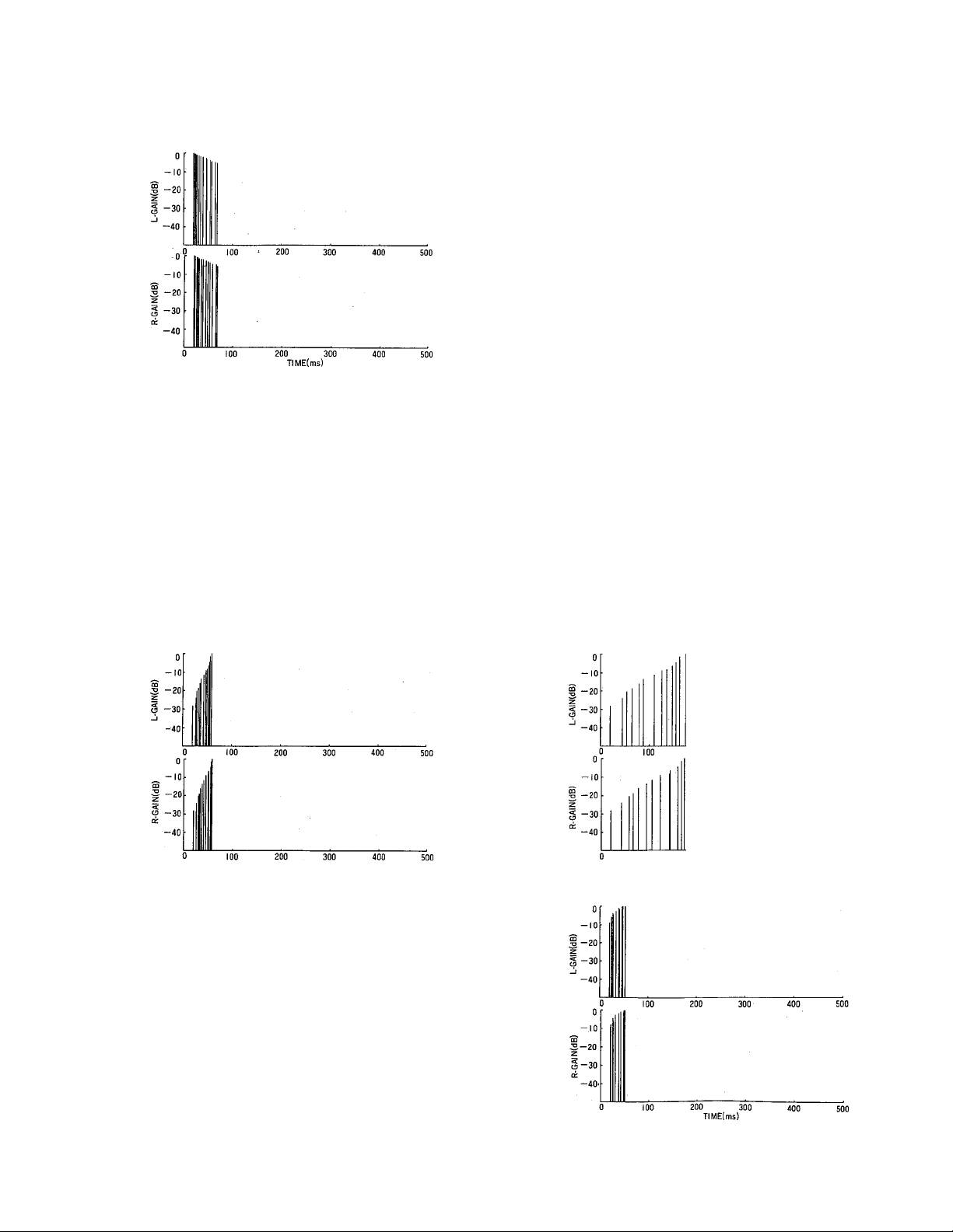
EARLY REFLECTION MODE CHART
-10
3 -20
2
S -30
-40
-10
s
3 -20
2
S -30
cc
-40
ROOM SIZE : 1.0
HALL
-10
3 -20
Z
^ -30
0
ROOM SIZE : 4.0
0
-10
Ì -20
I -30
-40
200 300
TIME(ms)
0
0
ROOM SIZE : 1.0
100 200 300 400
100 200 300 400
TIME(ms)
RANDOM
ROOM SIZE : 4.0
200 300
TIME(ms)
-10
g -20
I -30
-40
Ò '
-io
3
3 -20
z
Ц -30
ck
-40
ROOM SIZE : 1.0
TIME(ms)
0
ROOM SIZE : 1.0
200 300
TlME(ms)
REVERSE
PLATE
ROOM SIZE : 4.0
200 300
100 200 300 400
TIME(ms)
ROOM SIZE : 4.0
27
Page 29
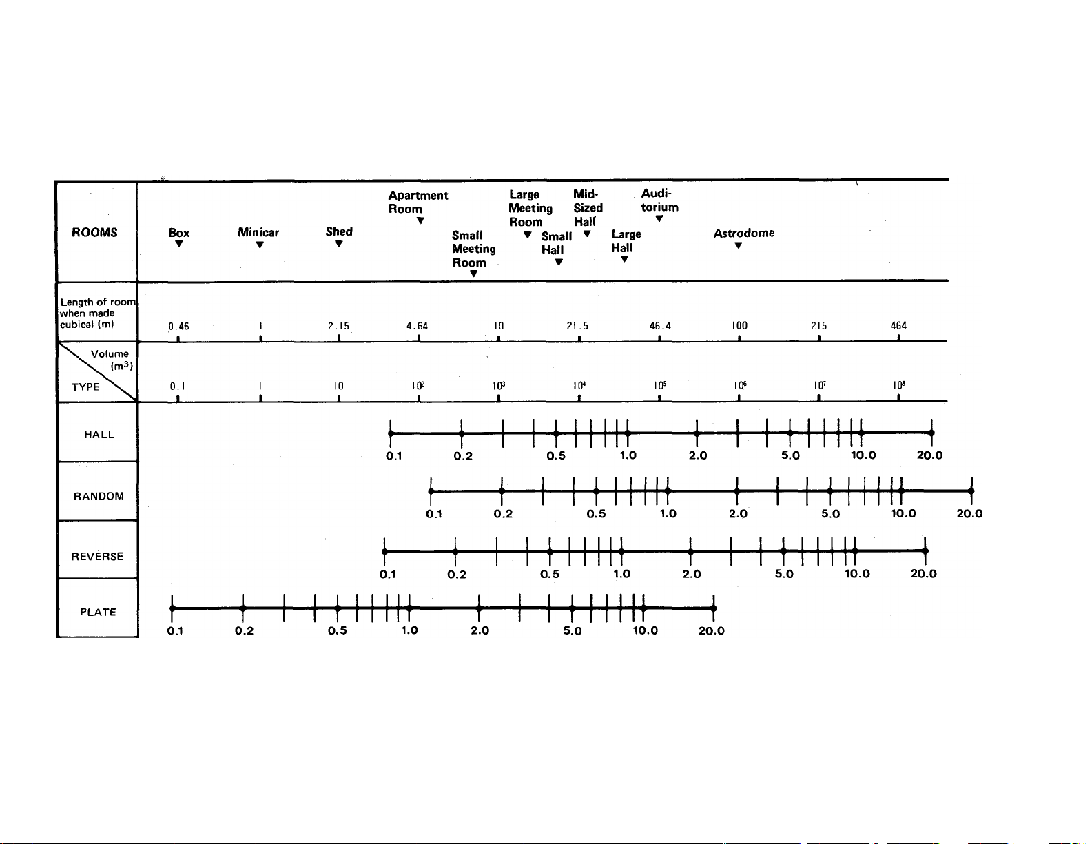
о
о
Ñ
m
П
X
>
ro
00
Page 30
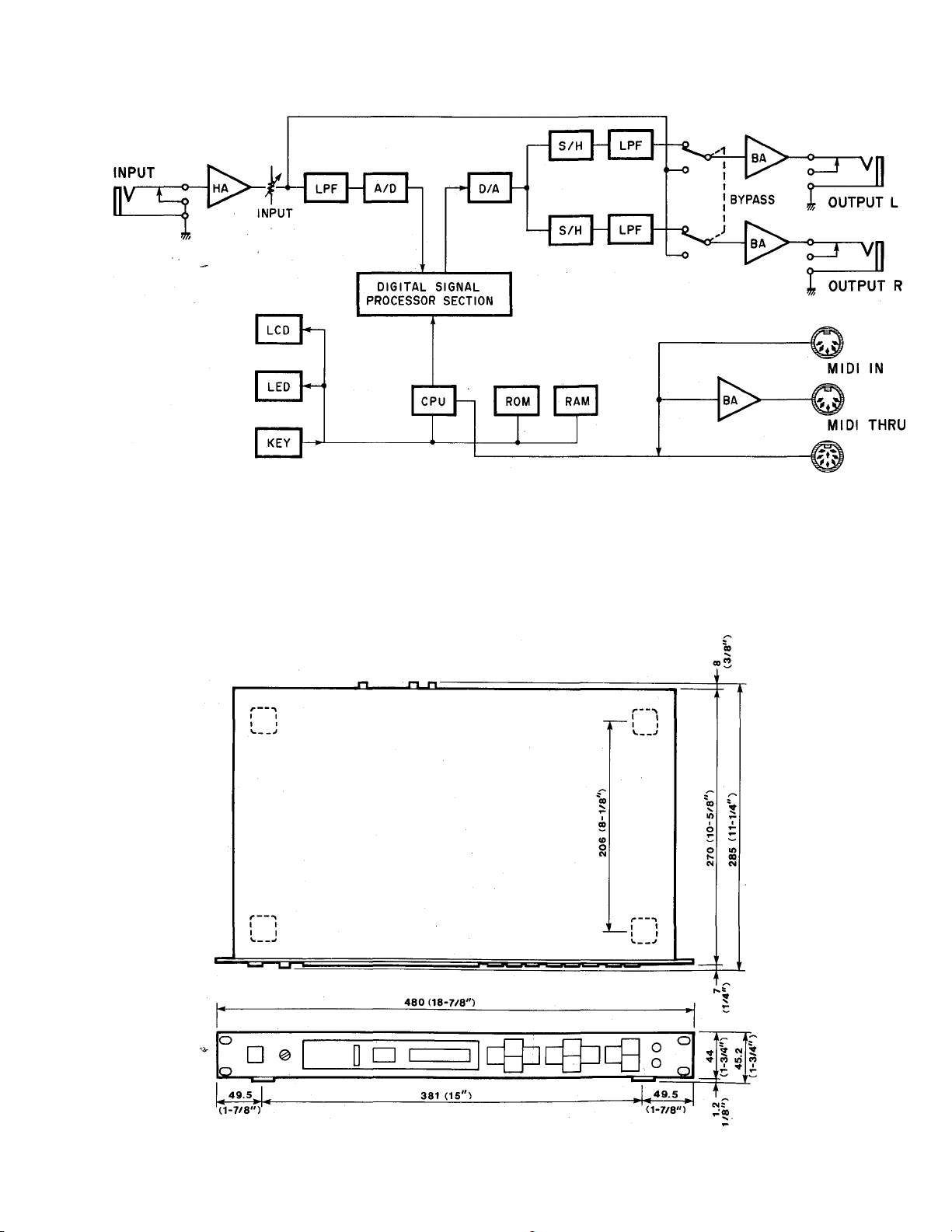
BLOCK DIAGRAM
REMOTE
CONTROL
DIMENSIONS
29
Unit : mm (Inch)
Page 31

USER PROGRAMMING TABLE
Program No.
Program Title
Parameter
■ Remarks ■
New Value
Type
Parameter New Value
Program No.
Program Title
Parameter
- Remarks
Type
New Value Parameter
New Value
30
Page 32

C Digital Sound proceeaor ] Date i 11/28, 1986
Model SPX90-2 MIDI Implementation Chart Version : 1.0
Recognized
Function
Basic Default *. 1-16
Channel Changed ; 1 - 16
Mode
Default
Messages
Altered
OMNI OFF/OMNI ON
X
X
Note ' ; o 0 - 127
Number ; True voice: x
Velocity Note ON : x
Note OFF : x
After
Touch
Pitch Bender
Key’s
Ch's
X
X
: X
+—
X
Control
Remarks
: memorized
memorized
XI :
Change
Prog
Change
True #
System Exclusive : o
----------------------------------
------
System ; Song Pos ; x
: Song Sel : x
Common : Tune : x
System : Clock : x
Real Time : Commands: x
Aux :Local ON/OFF : x
:A11 Notes OFF: x
Mes- ’.Active Sense *. x
sages:Reset : x
0 - 127
lt:2
31
Notes Xl Note ON/OFF is recognized only for pitch
change and freeze B.
X2 For program 1 - 128, memory #1 - #90 is
selected.
+
------------
Mode 1
Mode 3
OMNI ON, POLY Mode 2
OMNI OFF, POLY Mode 4
OMNI ON, MONO
OMNI OFF, MONO
o
Yes
X
No
Page 33

SERVICE
The SPX90II is supported by Yamaha's worldwide network of factory
trained and qualified dealer service personnel. In the event of a problem,
contact your nearest Yamaha dealer.
Page 34

c
Processeur multi-effets numérique
Manuel d^utilisation
Page 35

INTRODUCTION
Félicitations pour votre achat du Processeur multi-effets numérique SPX90II
Yamaha. Le SPX90II est le fruit de recherches combinées dans les domaines
de l’acoustique et de la synthèse numérique. Il a été conçu pour permettre aux
musiciens et aux amateurs d’enregistrement de produire toute une série d’effets
sensationnels.
Le SPX90I1 utilise une technologie LSI (Large Scale Intégration) de très haut
niveau pour produire une réverbération naturelle. Non seulement le SPX90II
possède un assortiment de 30 effets pré-programmés, largement suffisant pour
la plupart des applications en studio ou sur scène, mais il vous permet en outre
de créer vous-même jusqu’à 60 effets supplémentaires que vous pouvez stocker
en mémoire et rappeler à tout moment.
Votre SPX90IIpeut créer bien d’autres effets que la simple réverbération, encore
que celle-ci soit d’une qualité exceptionnelle. Toute un série d’échos, de retardements et d’autres effets spéciaux peuvent être sélectionnés par une simple
pression sur une touche. Et comme le SPX90II est compatible MIDI, il peut
être programmé pour appliquer des effets de réverbération différents à toute
une série d’instruments compatibles MIDI.
Votre processeur multi-effets numérique se révélera extrêmement utile dans de
nombreuses situations: que ce soit avec des instruments acoustiques, électriques,
PA ou MIDI ou avec votre système d’enregistrement personnel. Afin de tirer
le meilleur parti possible des nombreuses possibilités de cet appareil, nous vous
recommandons de bien étudier ce manuel avant de connecter le SPX90II à votre
système.
Nous vous remercions et nous vous souhaitons de nombreuses heures d’agrément
avec votre SPX90II.
TABLE DES MATIERES
PRECAUTIONS........................................................... 2
PANNEAU AVANT
PANNEAU ARRIERE
OPERATIONS DE BASE.............................................. 5
SELECTION DE PROGRAMMES
PREREGLES
EDITER; CHANGER LES PARAMETERS
STOCKER: SAUVEGARDER LES
PROGRAMMES EDITES...................................... 6
PROGRAMMER LA BALANCE ET LE
NIVEAU DE SORTIE
BYPASS (Dérivation)
FONCTIONS UTILITAIRES
EDIT TITLE
FONCTIONS MIDI
SPECIFICATION DES MEMOIRES QUI
POURRONT ETRE RAPPELEES AU MOYEN
DE LA COMMANDE AU PIED:.............................. 9
DESCRIPTION DES PROGRAMMES ET
DES PARAMETRES
REVERB.............................................................. 10
ER1, ER2 (Early Reflections)
DELAY................................................................. 11
ECHO
.................................................................
MODULATION
STEREO FLANGE............................................ 12
......................................................
...................................................
.........................................................
..........
.............................................
........
..................................... 7
.........................................
............................................................
.................................................
.......
.......................................... 10
..............................
3
4
5
5
7
8
8
8
10
11
CHORUS........................................................... 12
STEREO PHASING
TREMOLO......................................................... 13
SYMPHONIC
PITCH CHANGE
FREEZE
REVERB & GATE
GATE
PAN
DELAY VIBRATO................................................. 19
PARAMETRIC EQ
EXEMPLES D'APPLICATIONS................................. 21
CARACTERISTIQUES TECHNIQUES
FQRMAT DES DQNNEES MIDI
CQNTENU DE LA ROM ET PARAMETRES
PROGRAMMABLES
TABLEAU DU MODE EARLY REFLECTION
DIMENSIONS DU LOCAL.......................................... 28
SCHEMA FONCTIONNEL
DIMENSIONS
TABLEAU DE PROGRAMMATION DE
L'UTILISATEUR.......................................................... 30
TABLE DES CARACTERISTIQUES MIDI
...............................................................
ADR-NOISE GATE
COMPRESSOR.....
PAN
.........
.......................................................... 19
TRIGGERED PAN
......
.....................................................
..........................................
....................................................
.................................................
................................................
...........................................
...........................................
............................................
...............................................
......................
................................
..................................................
.............
.........................................
..................
13
13
13
14
17
17
18
19
20
23
24
25
27
29
29
31
Page 36

PRECAUTIONS
REMARQUE: Il est essentiel de lire attentivement ce chapitre avant de faire fonctionner le Processeur multi-effets
numérique SPX90II. Cette appareil est à la pointe de la technologie actuelle en matière de synthèse
numérique et il a été conçu pour fonctionner sans problème pendant de nombreuses années, mais
il doit néammoins être manipulé avec précaution.
• VOLTAGE
Assurez-vous que le voltage correspond bien aux
spécifications de votre appareil. Modèle pour les
Etats-Unis et le Canada; 110V- 120V, 50/60HZ.
Modèle standard: 220 — 240V, 50/60HZ.
• TEMPERATURE ENVIRONNANTE
N'exposez pas votre SPX90II à des températures
excessives. Cet appareil a été conçu pour fonc
tionner à des températures allant de 0 à 40 degrés
centigrades (32 à 104 degré Fahrenheit).
• NETTOYAGE DE L'EXTERIEUR
Evitez de nettoyer l'extérieur avec des solvants tels
que la benzine ou les diluants pour peinture. Enlevez
la poussière, les taches et les traces de doigts au
moyen d'un chiffon doux et sec. Le nettoyage de
l'intérieur de cet appareil doit absolument être confié
à un technicien qualifié. Il se peut que le LCD ne
fonctionne pas correctement lorsque la température
est trop élevée. Il fonctionnera à nouveau correc
tement lorsque la température sera redevenue
normale.
•
• PILE DE MAINTIEN
Afin d'éviter que les programmes de l'utilisateur
ne soient perdus lorsque le SPX90II est mis hors
tension, le contenu de la mérhoire est maintenu
par une pile de longue durée. Lorsque l'appareil
est utilisé normalement, cette pile dure environ 5
ans, mais il est conseillé de la remplacer plus tôt.
Contactez votre revendeur Yamaha pour plus de
détails.
REMARQUE; Lorsque vous remplacez la pile, les
programmes de l'utilisateur sont effacés de la mé
moire. Aussi, nous vous conseillons de recopier tous
les paramètres des programmes de l'utilisateur dans
le tableau des programmes de l'utilisateur joint à
ce manuel avant d'effectuer cette opération, puis
de les reprogrammer une fois que la nouvelle pile
est en place. Les programmes préréglés ne seront
pas affectés par le remplacement de la pile de
maintien.
MESSAGES D'ERREUR
Lorsque l'appareil est mis sous tension, un pro
gramme de contrôle automatique des circuits est
effectué pour vérifier que tout fonctionne correc
tement. Si une erreur est rencontrée, l'un des
messages d'erreur suivants est affiché:
EO: erreur au niveau de la somme de contrôle
ROM
El: erreur de lecture/écriture au niveau CPU
RAM
E2: erreur de lecture/écriture au niveau de la
RAM externe
Prenez note du message d'erreur et contactez le
service d'entretien lorsque cette appareil doit être
révisé.
Précautions à prendre lors de la manipulation du Matériel de Sonorisation
Ne pas placer le coffret et les composants dans les lieux suivants:
* Lieux exposés directement au rayonnement solaire.
* Lieux stiués au voisinage d'une source de chaleur et pouvant être soumis
à une élévation excessive de température.
* Lieux humides ou poussiéreux.
* Lieux soumis à des vibrations excessives.
Ne pas utiliser, pour le nettoyage de l'appareil, de dissolvants ou de solutions
similaires; éviter aussi toute vaporisation d'insecticides de type aérosol au
voisinage de l'appareil (les dissolvants et les insecticides de type aérosol
provoquent, souvent, en effet, la décoloration). Nettoyer l'appareil en
l'essuyant avec un tissu doux et sec.
Avant la mise en marche, il convient de réduire le volume au minimum, afin
d'assurer la protection du matériel branché.
Ne rien placer sur le bloc dissipateur dechaleur. L'effet dedissipationdechaleur
s'en trouverait réduit d'autant et un foncionnement défectueux pourrait en
résulter.
Ne jamais forcer lors de la manipulation des interrupteurs, des boutons et des
bornes.
La manipulation de l'appareil doit s'effectuer soigneusement. Toute mani
pulation brutale - telle que choc contre un objet dur ou chute à terre - peut
avoir une incidence fâcheuse sur les performances du matériel.
Abstenez-vous de modifier ou de re-structurer l'appareil, afin d'éviter tout
mauvais foncitonnement ou toute défaillance.
Assurez-vous que les branchements avaec les autre éléments sont correctement
effectués et notez que le courant doit toujours être coupé avant d'effectuer
tout branchement. Si le bloc doit être déplacé, détachez au préalable tous les
conducteurs, afin d'éviter tout dommage et tout risque de court-circuit.
Précautions à prendre lors de la manipulation de l'appareil fonctionant
sur courant alternatif
* Assurez-vous que la source d'alimentation correspond au voltage nominal
approprié. Ne jamais brancher l'appareil avec une prise ne possédant pas le
voltage nominal approprié.
* Si l'appareil doit rester inutilisé pendant une longue période, il convient de
débrancher la prise d'alimentation.
* Par temps orageux, débrancher immédiatement l'appareil de la source
d'alimentation, afin d'assurer la protection de ce dernier.
* Evitez de toucher l'interrupteur d'alimentation ou de brancher/débrancher la
prise courant alternatif ou la prise entrée/sortie, avec des mains humides.
Précautions à prendre fors de la manipulation de l'appareil fonctionant
sur piles
* Si l'appareil doit rester inutilisé pendant une longue période, retirer les piles
et les conserver en lieu sûr, afin d'éviter tout dommage résultant de fuites.
* Utilisez l'adaptateur courant alternatif exclusivement conçu pour l'appareil.
Il convient de noter que certains adaptateurs ont une polarité différente.
^ Lors de l'insertion des piles, assurez-vous que les polarités sont correctes.
Toute erreur risque de provoquer un fonctionnement défectueux de l'appareil.
Précautions à prendre lors da la maniupulation de l'ampli, et du
hautparleur doté d'un ampli, incorporé
^ Ne pas fournir au haut-parleur une puissance supérieure à celle admissible.
^ Utiliser un haut-parleur dont l'impédance reste à l'intérjeur des limites données
par l'ampli.
Page 37

PANNEAU AVANT
0 Commutateur de mise sous tension
Lorsque l'appareil est mis sous tension, le programme
qui a été sélectionné en dernier lieu avant que l'appareil
n'ait été mis hors tension est re-sélectionné. Le
SPX90II ne produira aucun son pendant quelques instants
après sa mise sous tension en raison de l'intervention d'un
circuit de sécurité qui coupe le son.
O Commande de réglage du niveau d'entrée
Règle le niveau du signal entrant. Réglez la commande
du niveau d'entrée en fonction de l'indicateur de niveau
d'entrée. Les 7 segments à LED de l'indicateur ne doivent
pas tous être allumés en permanence lorsqu'un signal est
entré car cela est susceptible de saturer l'amplificateur
et de produire des distorsions. Lorsque la commande de
réglage du niveau d'entrée est sur la position "8", le rapport
de gain entrée/sortie équivaut à 1. Lorsque cette com
mande est réglée sur la position "10", le gain est d'environ
10 dB.
0 Indicateur de niveau d'entrée
Cet indicateur de niveau à LED très lisible vous aidera à
régler les niveaux d'entrée de manière adéquate. Géné
ralement, le meilleur réglage est celui pour lequel les
segments à LED inférieurs (verts) restent allumés en
permanence et les segments supérieurs (rouges)
s'allument de manière occasionnelle.
O Affichage à LED du numéro de mémoire
Cet affichage à LED numérique indique le numéro du
programme actuellement sélectionné. Les mérrioires 1 à
30 contiennent les effets pré-réglés en usine (ROM)
tandis que les mémoires 31 à 90 peuvent utilisées pour
stocker des versions éditées des effets pré-réglés (RAM).
0 Indicateur LCD des programmes et des paramètres
Ce panneau LCD très contrasté indique le nom des pro
grammes et la valeur affectée aux différents paramètres.
0 Touche de paramètre
Cette touche permet de sélectionner les paramètres
d'effets l'un après l'autre. Appuyez sur cette touche de
manière répétée pour appeler les différents paramètres
programmables du programme d'effets sélectionné. En
suite, lorsque vous avez sélectionné le paramètre désiré,
utilisez les touches d'incrémentation et de décrémentation
pour modifier la valeur de ce paramètre et donc modifier
l'effet. Les paramètres disponibles sont différents pour
chaque programme (cf. tableau des paramètres à la page
24).
0 Touches d'incrémentation et de décrémentation
des paramètres
Ces touches servent à changer la valeur du paramètre
sélectionné. Appuyez sur la touche d'incrémentation (la
flèche tournée vers le haut) pour augmenter la valeur et
sur la touche,¿e décrémentation (la flèche tournée vers
le bas) pour diminuer la valeur.
0 Touche de niveau de sortie/Balance
Cette touche permet de régler l'importance du signal
d'effet par rapport au signal direct. Lorsque vous enfoncez
cette touche, le LCD affiche en alternance la balance et
le niveau de sortie actuels. Utilisez alors les touches
d'incrémentation et de décrémentation pour modifier les
valeurs affichées.
O Touche STORE (Stockage)
Cette touche permet de stocker dans un emplacemerit
de la mémoire RAM (31 -90) sélectionné les paramètres
édités de n'importe quel effet pré-réglé.
0 Touches d'incrémentation et de décrémentation
de mémoire
Ces touches permettent de sélectionner les numéros de
mémoire afin d'appeler un programme particulier ou de
stocker un programme édité dans la zone de la mémoire
accessible à l'utilisateur. Le numéro de mémoire sélec
tionné est indiqué sur l'affichage du numéro de mémoire.
Lorsqu'un nouveau numéro de mémoire est appelé, le
numéro affiché clignote jusqu'à ce que soit la fonction
STORE, soit la fonction RECALL soit activée.
0 Touche RECALL (Rappel)
Appuyez sur cette touche pour rappeler le programme
stocké sous le numéro de mémoire sélectionné.
0 Touche UTILITY (Utilitaire)
Cette touche multi-fonctionnelle permet d'accéder aux
fonctions de commande MIDI qui facilitent l'édition du
titre de programme et règlent le nombre de mémoires
accessibles via la commande au pied. Pour plus de détails,
voir pp.8 et 9.
0 Touche FOOT/ TRIGGER
Lorsque cette touche est enfoncée et que son témoin à
LED est allumé, la commande au pied connectée à fa prise
Memory/ Trigger sert à enclencher les programmes GATE
et FREEZE, et non plus à sélectionner les mémoires.
0 Touche BYPASS (Dérivation)
Lorsque cette touche est enfoncée, le signal d'effet est
coupé. Seul le signal direct est sorti. Le niveau du signal
direct est affecté par la valeur fixée pour la commande
de réglage du niveau d'entrée (INPUT LEVEL).
0 Prise pour commande au pied Memory/ Trigger
C'est à cette prise que se branche la commande au pied,
disponible en option, destinée à permettre la sélection à
distance des mémoires. Le nombre des mémoires qui
peuvent être appelées via la commande au pied peut être
fixé au moyen d'un programme utilitaire. Lorsque la
fonction Foot Trigger (cf. ci-dessus) est active, la com
mande au pied connectée à cette prise fait fonction de
pédale de déclenchement plutôt que de sélecteur de
mémoires à distance. Nous vous recommandons d'utiliser
une commande au pied FC-5 Yamaha.
0 Prise pour commande au pied BYPASS
Branchez à cette prise une commande au pied afin de
pouvoir contrôler aisément la fonction BYPASS. Nous
vous recommandons d'utiliser une commande au pied
FC-5 Yamaha.
Page 38

PANNEAU ARRIERE
Mdèle pour les Etats-Unis et le Canada
Connecteur pour commande à distance
Cette prise permet de télécommander le SPX90II par
l'intermédiaire d'une unité de commande à distance RC7
(disponible en option). Cette dernière permet d'accéder
directement aux programmes 1 à 7 et 31 à 37. Les autres
programmes pré-réglés sont accessibles en séquence.
BEV1 REV 2 REV 3
Ce témoin à LED s'allume
lorsqu'une touche de la
commande à distance est
enfoncée. I
Lorsque ce témoin à LED
est allumé, il est possible
d'appeler les programmes
de l'utilisateur.
-31- -32-\-33-
17 ~
-----
,1
---------
I P
1,
_____,,_______
REV 4 E/R 1 E/R 2
-34- -35- -36-
-0 KEY ON
^ USER
;; —il
-----------------------------
,,----------,1
YAMAHA
1|
■ Touches de
pré-sélections
Lorsque cette touche
est enfoncée, le témoin
à LED USER s'allume et
il devient possible
d'appeler les programmes
de l'utilisateur 31 à 37.
0 Borne MIDI THRU
Les données MIDI reçues sur la borne MIDI IN sont re
transmises par cette borne aux instruments situés en aval.
0
Borne MIDI IN
Les programmes d'effets du SPX90II peuvent être sé
lectionnés automatiquement au moyen d'un signal MIDI
envoyé à cette borne. Cette borne doit être connectée à
la borne MIDI OUT de l'appareil émetteur au moyen d'un
câble MIDI standard.
O Sélecteur de niveau de sortie (-20 dB, +4 dB)
Permet de faire correspondre le niveau source/ligne
(sensibilité) du SPX90II.
0
Prises de sortie OUTPUT (G et D)
Ces prises sont des prises audio mono standard de 1 /4
de pouce qui sortent le signal direct et le signal d'effet
vers les appareils de mixage et d'amplification situés en
aval. La sortie du SPX90II étant stéréo, nous vous re
commandons d'envoyer le signal en stéréo à un système
stéréo afin de profiter pleinement des superbes effets
stéréo produits. L'impédance de sortie est de 600 ohms.
0 Sélecteur de niveau d'entrée (-20 dB, -i-4 dB)
Permet de faire correspondre le niveau source/ligne
(sensibilité) du SPX90II.
0 Prise d'entrée
Cette prise audio mono standard asymétrique de 1/4 de
pouce reçoit le signal entrant. L'impédance d'entrée est
de 10 kohms.
Témoin à LED USER éteint
—Programmes pré-réglés—
1. REV 1 HALL
2. REV 2 ROOM
3. REV 2 VOCAL
4. REV 4 PLATE
5. EARLY REFLECTION 1
6. EARLY REFLECTION 2
7. DELAY L, R
1
30. (Les programmes 8 à 30
1
peuvent être sélectionnés
l'un après l'autre en appuyant
sur ta touche OTHERS/-37-).
Témoin à LED USER allumé
—Programmes de l'utilisateur—
31. Programme de l'utilisateur
32. Programme de l'utilisateur
33. Programme de l'utilisateur
34. Programme de l'utilisateur
35. Programme de l'utilisateur
36. Programme de l'utilisateur
37. Programme de l'utilisateur
Page 39

OPERATIONS DE BASE
Avant de sélectionner ou d'éditer des programmes sur votre SPX90II, assurez-vous que toutes les connexions ont
été correctement effectuées et que le commutateur de niveau d'entrée (INPUT LEVEL), le commutateur de niveau
de sortie (OUTPUT LEVEL) et la commande INPUT LEVEL ont été correctement réglés en fonction du signal source
et de l'appareil auquel le SPX90II envoie son signal.
/SELECTION DES PROGRAMMES /
/ PRE-REGLES
Votre SPX90II possède 30 superbes programmes
d'effets pré-réglés énumérés à la page 24 sous le titre
CONTENU DE LA ROM ET PARAMETRES PRO
GRAMMABLES. Pour sélectionner les programmes
pré-réglés et les programmes de l'utilisateur, opérez
de la manière suivante:
1. Utilisez les touches d'INCREMENTATION/
DECREMENTATION MEMOIRE pour sélectionner
le numéro de mémoire souhaité (rappelez-vous que
les numéros 1 à 30 sont affectés aux programmes
pré-réglés).
2. Appuyez sur la touche RECALL pour appeler le
programme stocké sous le numéro de mémoire
sélectionné.
______________________________
/
PGM actuellement utilisé
/
A
/ EDITER: CHANGER LES PARAMETRES^
Le SPX90II offre de très nombreuses possibilités
d'effets sonores dans la mesure où chaque type d'effet
possède son propre jeu de paramètres (cf. le tableau
des paramètres à la page 24). Vous pouvez régler ces
paramètres en fonction de vos goûts et des caracté
ristiques tonales de vos appareils. Nous vous
conseillons d'examiner chacun des programmes
d'effets pré-réglés et d'observer la manière dont ces
paramètres affectent le son. Vous découvrirez très vite
de nombreuses nouvelles applications passionnantes
pour les programmes d'effets pré-réglés du SPX90II.
1. Sélectionnez et rappelez le programme souhaité
de la manière décrite ci-dessus.
2. Appuyez sur la touche PARAMETER pour accéder
aux différents paramètres disponibles dans le pro
gramme sélectionné. Chaque fois que vous appuyez
sur la touche PARAMETER, le paramètre suivant
dans la liste est appelé.
\ W 'n I
/1
111
REMARQUE: Le même procédé est utilisé pour
appeler les programmes de l'utilisateur
(mémoires numérotées de 31 à 90),
une fois que vous avez stocké vos
propres programmes dans la mémoire
accessible à l'utilisateur.
r
\ \\
\ Mil//
J
I I M
J
/
Clignote—
------
Clignote—
-est allumé—
Page 40

3. Utilisez les touches d'INCREMENTATION/
DECREMENTATION DE PARAMETRE pour fixer
la valeur souhaitée pour le paramètre sélectionné.
STOCKER: SAUVEGARDER LES PRO-
l GRAMMES EDITES
____________________
RE V 3
VO CAL
RE V TIÎvIE = 2.4 .s
’ '
RE V 3
VO CAL
HIGH = 0 .5
A
'
RE V 3
HIGH
REMARQUE: Le chapitre DESCRIPTION DES
VO CAL
= 0 .8
PROGRAMMES ET DES PARAME
TRES (page 10) décrit chaque para
mètre et explique les effets qu'il pro
duit.
Nouvelle valeur
Lorsque vous avez édité des paramètres dans un pro
gramme pré-réglé, les modifications que vous avez
apportées ne seront conservées que jusqu'au moment
où vous sélectionnerez (RECALL) un autre pro
gramme. Cependant, la fonction STORE vous permet
de sauvegarder le programme édité dans l'une des
mémoires accessibles à l'utilisateur (numéros 31 -90),
à partir de laquelle il pourra être rappelé à tout moment.
1. Sélectionnez et éditez un programme comme décrit
ci- dessus.
2. Utilisez les touches d'INCREMENTATION ET DE
DECREMENTATION DE MEMOIRE pour sélec
tionner une mémoire vide (entre 31 et 90).
3. Appuyez sur la touche STORE.
Le programme édité a maintenant été stocké dans
remplacement sélectionné de la mémoire de
l'utilisateur. Le programme stocké peut être rappelé à
tout moment, de la même façon que les programmes
pré-réglés.
REMARQUE: Si vous essayez de stocker un pro
gramme dans l'un des emplacements
réservés aux programmes pré-réglés,
(1 à 30), le SPX90II affichera le
message d'erreur "#1 ~#30 READ
ONLY" (no 1 à 30 lecture uni
quement).
Le SPX90II possède une fonction
"Title Edit" qui vous permet de donner
un nom original à vos programmes
édités (cf. FONCTIONS UTILITAIRES
à la page 8).
Page 41

PROGRAMMER LA BALANCE ET LE N1-
I VEAU DE SORTIE
La touche BALANCE permet de sélectionner les
fonctions BALANCE et OUTPUT LEVEL pour tous les
programmes.
1. Appuyéz sur la touche BALANCE lorsqu'un para
mètre quelconque est sélectionné.
2. La première fonction appelée est la fonction BA
LANCE. Réglez la balance entre 0 et 100% en vous
servant des touches d'INCREMENTATION/
DECREMENTATION DE PARAMETRE.
* Balance = 100% : signal d'effet uniquement
Balance = 0% : signal direct uniquement
3. Appuyez à nouveau sur la touche BALANCE pour
appeler la fonction OUTPUT LEVEL et réglez
celle-ci en vous servant des touches
d'INCREMENTATION/DECREMENTATION DE
PARAMETRE.
* OUT LVL = 100% : niveau de sortie maximal
OUT LVL = 0% : aucun son ne sortira
BYPASS (Dérivation)
Lorsque la touche BYPASS est enfoncée et que son
témoin à LED est allumé, le signal d'effet est supprimé
et seul le signal direct entrant est émis via les prises
OUTPUT. Les fonctions BALANCE et OUTPUT LEVEL
sont également affectées par la fonction BYPASS.
La fonction BYPASS peut également être activée au
moyen d'une commande au pied connectée à la prise
BYPASS. Utilisez une commande au pied de type
"normalement fermée" telle que la FC-5 Yamaha.
1
1
'
REV 3 VOCAL
BALANCE = 100 %
1
Î
_______
REV 3 VOCAL
BALANCE = 50 7.
'
REV 3 VOCAL
OUT LVL = 100 %
__________
1
l
________
REV "3 VOCAL
OUT LVL = 90 %
CD
A
ETEB
J
1
______
S
A
a
■
A
V,
&0
Page 42

FONCTIONS UTILITAIRES
La touche UTILITY permet d'accéder à quatre fonctions
utilitaires. Ces fonctions sont sélectionnées dans
l'ordre, l'une après l'autre, chaque fois que la touche
UTILITY est enfoncée.
.Mode normal .EDIT TITLE ^ MIDI CONTROL ->
MIDI PROGRAM CHANGE -> FOOTSWITCH
MEMORY RECALL - Mode normal.
Le témoin à LED de la touche UTILITY s'allume lorsque
l'une des quatre fonctions utilitaires est sélectionnée
et s'éteint lorsque l'on repasse en mode normal.
Lorsque le témoin à LED de la touche UTILITY est
allumé, les touches d'INCREMENTATION/
DECREMENTATION DE PARAMETRE ET DE ME
MOIRE ont une fonction particulière, décrite
ci-dessous. Il n'est donc pas possible de sélectionner
les paramètres et les mémoires en dehors du mode
normal.
EDIT TITLE
à
1
Cette fonction permet de donner de nouveaux noms
aux programmes que vous avez édités et stockés dans
la mémoire de l'utilisateur (numéros 31 à 90). Lorsque
la fonction EDIT TITLE est appelée, la ligne inférieure
du LCD indique le nom de la fonction; "EDIT TITLE"
et la ligne supérieure indique le nom du programme
actuellement sélectionné. A ce moment, les touches
BALANCE et PARAMETER peuvent être utilisées pour
déplacer le curseur vers la gauche et vers la droite, c'est-
à-dire pour sélectionner les caractères à remplacer.
Amenez le curseur sur un caractère, puis utilisèz les
touches d'INCREMENTATION/DECREMENTATION
DE PARAMETRE pour parcourir la liste des caractères
disponibles. Arrêtez d'appuyer lorsque le caractère
souhaité est affiché et déplacez le curseur vers la case
suivante. Répétez cette opération jusqu'à ce que le
nouveau nom soit terminé. Les caractères disponibles
sont les suivants:
D E
1
m
[ ]
- *
? y
7 U
F
n
<
i-
0
1
#
H
G
1
Y Z a
0 0
P q
>
•
r
J
y □
V-
7
U P
3 4 5 6
2
K
J
a b C d
r S t
*
-h
-
•>
7.
9
7
L
M N
=
T
7 ■r <
-tz V
■7iA
7
0
e f
U U V
&
/
7
8
P
0 7
7
9
R
Q
h
g
X
W
X
T 1-
'y
-f -V'
A B C
S T
i
i
Z
y
!
%
X .
X
JXa3
UVW X
k
?
FONCTIONS MIDI
Avec le SPX90II, il est possible de sélectionner des
programmes spécifiques via une commande MIDI
externe. Par exemple, vous pouvez régler le SPX90II
de façon à ce que lorsque vous sélectionnez un son
spécifié sur votre synthétiseur MIDI, le programme
d'effet le plus approprié pour ce Son soit automati
quement sélectionné. Dans ce cas, le SPX90II détecte
le signal de changement de programme MIDI. Pour
les programmes suivants, le SPX90II détecte
également les signaux MIDI de touche enfoncée et
de touche relâchée:
* programmes GATE (GATE ON/OFF)
* programmes PITCH (règlent la hauteur)
* programmes FREEZE (commencent la repro
duction).
Pour les opérations de changement de programme
MIDI, il est possible de programmer quatre jeux in
dépendants de combinaisons changement de pro
gramme/ numéro de mémoire, appelés "banks" dans
le contexte du SPX90II. Vous pouvez programmer une
combinaison différente dans chaque bank, ainsi que
le montre l'illustration ci-dessous.
— Canal de réception
BANK:B
“ch/*
PGM 1 =MEM 1 PGM 1 =MEM 6
PGM 2 =MEM 4 PGM 2 =MEM 7
PGM 3 =MEM 8 PGM 3 =MEMI6
PGMI28 = MEM40 PGMI28=MEM 1
Numéro de mémoire du SPX90
Numéro de programme de son
BANK:C
CH = 15
PGM 1 =MEM90
PGM 2 =MEM89 PGM 2 =MEM2
PGM3 =MEM88
PGMI28 = MEM40
* Le bank D retrouve son réglage initial (n° de programme =
n° de mémoire) lors de chaque mise sous tension.
La deuxième fonction à laquelle la touche UTILITY
donne accès—MIDI CNTRL—permet de sélectionner
le Bank et de fixer le numéro de canal MIDI sur lequel
les données de changement de programme pour ce
BANK seront reçues. La troisième fonction sélection
née au moyen de la touche UTILITY—MIDI PGM
CHANGE—permet de fixer le numéro de mémoire SPX
qui est appelé lorsqu'un numéro de changement de
programme MIDI spécifié est reçu.
CH - 2
BANK:D
CH=OMNI
PGM 1 =MEM 1
PGM3 =MEM3
PGMI28 = MEM38
Page 43

Programmation du bank et du canal MIDI
Lorsque cette fonction est appelée, le LCD apparaîtra
sous la forme suivante:
MIDL CONTROL
BANK:x ch= xx
Utilisez les touches d'INCREMENTATION/
DECREMENTATION DE PARAMETRE pour sélec
tionner le BANK souhaité et les touches
d'INCREMENTATION/ DECREMENTATION DE
MEMOIRE pour sélectionner le numéro de canal MIDI
souhaité pour ce BANK. Lorsque "CH = OMNI" est
sélectionné, la réception sera possible sur les 16 canaux
simultanément. Lorsque "CH = OFF" est sélectionné,
la réception MIDI n'est pas possible.
a
A
---------
ETER
ç;
MIDI CONTROL
BANK:A ch= xx
Utilisez les touches d'INCREMENTATION/
DECREMENTATION DE PARAMETRE pour fixer le
numéro de programme MIDI (PGM) et utilisez les
touches d'INCREMENTATION /DECREMENTATION
DE MEMOIRE pour sélectionner le numéro de mémoire
du SPX90II (MEM) à appeler lorsque ce numéro de
programme est reçu. Par exemple, si "PGM 12 = MEM
4" est programmé, la mémoire numéro 4 du SPX90II
sera automatiquement appelée, chaque fois que vous
sélectionnerez le son numéro 12 sur votre synthétiseur
MIDI. Les numéros de programme MIDI vont de 1 à
128, tandis que les numéros de mémoire du SPX90II
vont de 1 à 90.
SPECIFICATION DES MEMOIRES QUI POURRONT ETRE RAPPELEES AU MOYEN DE LA COMMANDE AU PIED
Les mémoires du SPX90II peuvent être sélectionnées
au moyen d'une commande au pied branchée à la prise
MEMORY/TRIGGER du panneau avant. La quatrième
fonction à laquelle il est possible d'accéder par
l'intermédiaire de la touche UTILITY — FOOTSWITCH
MEMORY RECALL permet de spécifier les numéros
de mémoire qui pourront être sélectionnés au moyen
de la commande au pied.
Bank sélectionné
STORE
V
H
MIDI CONTROL
BANK:A ch= 1
Canal sélectionné
Programmation des combinaisons Numéro de
programme MIDI/Numéro de programme
SPX90.
Lorsque vous appelez cette fonction en appuyant une
nouvelle fois sur la touche UTILITY, le LCD se présente
sous la forme suivante:
MIDI PGM
PGMxxx
MIDI PGM
PGM 12
CHANGE
= MEM
XX
CHANGE
= MEM
XX
ETER
O
2l
F.SW MEMORY RCL
RANGE 1 TO 30
Si les mémoires 1 à 30 sont spécifiées, comme l'indique
l'illustration ci-dessus, les fonctions sont appellées
l'une après l'autre, dans l'ordre croissant. Une fois que
la dernière fonction de la série est atteinte, c'est la
première qui est à nouveau sélectionnée. Il est possible
de sélectionner les mémoires dans l'ordre décroissant
en mentionnant le numéro le plus élevé en première
position.
F,SW MEMORY RCL
RANGE 34 TO 31
Dans ce cas, les mémoires sont appelées dans l'ordre
suivant: 34 ^ 33 -> 32 -► 31.
MIDI PGM
PGM 12
'
CHANGE
= MEM ' 4
kl
vlO'
Page 44

г
DESCRIPTrON DES PROGRAMMES ET
DES PARAMETRES
Les programmes pré-réglés dans le SPX90II appartiennent aux catégories suivantes: REV (Reverb), ER1 et ER2 (Early
Reflections), DELAY, ECHO, MOD (Modulation), GATE, PITCH, FREEZE, PAN, VIBRATO et PEQ (parametric
equalizer). Chacune de ces catégories de programmes possède un jeu de paramètres programmables spécifique.
On entend par "paramètres" les différentes fonctions individuelles qui constituent un effet. Il existe deux types de
paramètres dans le SPX90II: les paramètres "invisibles" (paramètres non programmables dont la valeur est fixée)
et les paramètres programmables (ceux que vous pouvez éditer).
(Réverbération)
Généralement associée à la notion d"'ambiance" mu
sicale, la réverbération est le résultat d'une myriade
d'ondes sonores réfléchies dans un environnemetit
acoustique, c'est-à-dire une salle de concert, un au
ditorium ou la scène d'un studio d'enregistrement. Le
SPX90II permet de produire des effets de réverbération
particulièrement vibrants et naturels.
(TEMPS)
RETARD DUREE DE REVERBERATION
REVERBERATION TIME {R/T)(Temps de ré
verbération). Plage de réglage: 0,3 ~ 99,0
sec.
Le temps nécessaire pour qu'un effet de réverbé
ration dont le niveau est de 1 kHz descende à 60
dB, c'est-à-dire pratiquement au silence. Pour les
enregistrements en direct, cela dépend de plusieurs
facteurs: les dimensions de la salle, la forme de la
salle, le type de surface réfléchissante, etc.
2.
HIGH (Rapport de temps de réverbération
des hautes fréquences). Plage de réglage
0,1 ~ 1,0
La réverbération naturelle varie en fonction de la
fréquence du son — plus la fréquence est haute,
plus le son a tendance à être absorbé par les murs,
l'ameublement et même l'air. Ce paramètre vous
permet de modifier la durée de réverbération des
hautes fréquences en fonction de la durée de ré
verbération des moyennes fréquences.
DELAY (Retard). Plage de réglage: 0,1 ~
3.
1000,0 msec
Dans une salle de concert, il s'écoule un certain
temps entre le moment où le son est émis par
l'instrument et celui où le premier des nombreux
sons réfléchis qui constituent la réverbération atteint
l'auditeur. Sur le SPX90II, ce temps de retard est
appelé DELAY.
4.
HPF (High Pass Filter). Plage de réglage:
THRU, 32 Hz ~ 1,0 kHz
Permet de couper les composantes de basse fré
quence du signal de réverbération situées en des
sous de la fréquence fixée. Lorsque cette fonction
est commutée sur THRU, le HPF est désenclenché.
LPF (Low Pass Filter). Plage de réglage: 1,0
5.
kHz ~ 11 kHz, THRU
Permet de couper les composantes de haute fré
quence du signal de réverbération situées aü-dessus
de la fréquence fixée. Lorsque la fonction est réglée
sur THRU, le LPF est désenclenché.
ER1 et ER2 (Early Reflections)
ER1 possède moins de réflexions et constitue un effet
"Early Reflection" à FAIBLE DENSITE, tandis que ER2
possède plus de réflexions et est un effet "Early
Reflection" à HAUTE DENSITÉ.
DENSITÉ. EARLY ^type-
signal DIRECT / REFLECTIONS |||||||
RETARD
1. TYPE. Options: HALL, RANDOM, REVERSE,
PLATE
TYPE permet de sélectionner la structure des ré
flexions les plus précoces du son réfléchi. Toutes
les présélections "Early Reflections" peuvent être
de quatre types différents. Ceux-ci sont: HALL (un
groupement des réflexions précoces typique des
salles de concert), RANDOM (une série de ré
flexions irrégulière qui ne peut être produite na
turellement), PLATE (un groupement des réflexions
précoces typique des unités de réverbération plates)
et REVERSE (une série de réflexions qui augmen
tent en niveau comme lorsque l'on reproduit un
écho à l'envers). Cf. le tableau du mode E/R, à la
page 26.
2. ROOM SIZE (Dimensions de la salle. Plage
de réglage: 0,1 ~ 20,0
Le paramètre ROOM SIZE règle les intervalles de
temps entre les premières réflexions - proportion
nellement aux dimensions de la salle. L'effet de
ce paramètre dépend également du mode de "Early
Reflections "qui a été sélectionné. Vous trouverez
un tableau des dimensions du local à la page 27
de ce manuel.
3. LIVENESS Plage de réglage: 0 ~ 10
S'applique à la vitesse à laquelle les sons réfléchis
s'estompent. Réglez ce paramètre sur zéro pour
simuler une salle acoustiquement "morte", avec
des surfaces absorbantes pour absorber les sons
réfléchis. A mesure que vous augmentez la valeur
du paramètre, la salle semble posséder de surfaces
vives, les sons s'estompent, plus lentement, sem
blent se renvoyer de mur en mur. Lorsque le para
mètre est réglé sur la valeur maximale, l'effet cor
respond à celui produit dans un environnement
contenant de nombreuses surfaces lisses (tuiles,
verre, etc.).
4. DELAY. Plage de réglage: 0,1 ~ 1800,0 msec
Le temps qui sépare le moment où le son est émis
par l'instrument et celui où la première réflexion
atteint l'oreille de l'auditeur.
5. LPF. Plage de réglage: 1,0 kHz ~ 11 kHz,
THRU
Même fonction que le paramètre LPF des pro
grammes REV.
DIMENSIONS DE LA SALLE
r
10
Page 45

DELAY
ECHO
Cet effet, très largement utilisé dans les enregistrements
actuels, retarde de façon variable et indépendante les
signaux envoyés au canal gauche et au canal droit.
Le résultat est un son double "assez" troublant.
1. LEFT CHANNEL DELAY TIME (Temps de
retard sur le canal de gauche). Plage de ré
glage : 0,1 ~ 2000,0 msec.
Permet de fixer avec précision le retard du canal
de gauche sur le signal direct.
2. LEFT CHANNEL FEEDBACK GAIN (Gain de
feedback du canal de gauche ). Plage de
réglage: -99% ~ +99%
Règle la quantité de signal retardé renvoyée aux
circuits d'entrée. Plus le gain est important, plus le
nombre de répétitions du retard produites est grand.
Les valeurs négatives produisent un feedback
déphasé.
3. RIGHT CHANNEL DELAY TIME (Temps de
retard du canal de droite). Plage de réglage:
0,1 ~ 2000,0 msec
Permet de régler le retard du canal de droite.
Comme le retard, l'écho donne une dimension sup
plémentaire et une force accrue aux sons instrumentaux
et vocaux. Alors que la réverbération recrée une mul
titude de sons partiels réfléchis et que le retard produit
un nombre limité de répétitions du signal, l'écho, lui,
produit des répétions du signal en nombre illimité.
(dB)
SIGNAL DIRECT
I
I
L R
(TEMPS)
TEMPS
DE RETARD GAUCHE
-•
-------
H
TEMPS DE RETARD DROIT
1.
LEFT CHANNEL DELAY TIME (Temps de
retard du canal de gauche). Plage de réglage:
0,1 ~ 1000,0 msec
Lorsque ce retard s'est écoulé, le premier écho est
produit et les échos suivants sont produits avec le
même intervalle. Le nombre d'échos produits dé
pend du réglage du paramètre Feedback Gain.
2. LEFT CHANNEL FEEDBACK GAIN. Plage de
réglage: -99% ~ +99%
Ce paramètre permet de fixer le nombre des échos
qui suivront l'émission du signal direct, entre zéro
et l'infini pour la valeur maximale. Le temps que
met l'effet à s'estomper dépend du réglage du pa
ramètre Feedback Gain.
3. RIGHT CHANNEL DELAY TIME. Plage de
réglage: 0,1 ~ 1000,0 msec
4. RIGHT CHANNEL FEEDBACK GAIN (Gain
de feedback du canal de droite). Plage de
réglage: -99% à +99%
Permet de régler le gain de feedback pour le canal
de droite.
5. HIGH (FEEDBACK HIGH). Plage de réglage:
0,1 ~ 1,0
Commande le feedback de la bande de haute fré
quence. Le feedback en haute fréquence est
d'autant plus réduit que la valeur de ce paramètre
est basse.
11
4. RIGHT CHANNEL FEEDBACK GAIN. Plage
de réglage: -99% ~ +99%
Les paramètres 3 et 4 fonctionnent de la mpme
manière que les paramètres 1 et 2 mais le signal
sera envoyé à la sortie droite.
5. HIGH (FEEDBACK HIGH). Plage de réglage:
0,1 ~ 1,0
Détermine la portion de feedback en haute fré
quence. Plus la valeur est petite, moins il y a de
hautes fréquences.
Page 46

MODULATION
STEREO FLANGE
Combinaison du retard (Delay) et de la modulation
LFO (Oscillateur à basse fréquence), l'effet de
"Flanging" permet de rendre particulièrement ample
le son des instruments à clavier et de produire le "son
d'avion" bien connûmes guitaristes. En gros, un léger
temps de retard alterne avec la modulation LFO de sorte
que le signal retardé est modifié par rapport au signal
direct. Les variations qui en résultent en ce qui concerne
la hauteur et l'image stéréo sont appelées "flanging".
SIGNAL
(dB)
DIRECT
TEMPS DE RETARD MOD.
PROFONDEUR DE LA MODULATION
R(L)
(TEMPS)
CHORUS
Grâce à l'effet de chorus, un violon, un clavier ou une
guitare peuvent remplacer tout un ensemble. L'effet
de chorus partage le signal entrant en trois signaux
placés au centre, à gauche et à droite du panorania
stéréo. Chaque signal est légèrement décalé, puis son
temps de retard et son niveau sont modulés par le LFO
(oscillateur à basse fréquence).
(dB)
SIGNAL DIRECT
PROFONDEUR DE LA
MODULATION
D'AMPLITUDE
' (TEMPS)
PROFONDEUR DE LA
MODULATION DE RETARD
I
1. MOD FREQ. Plage de réglage: 0,1 40,0
Hz
Règle la vitesse de modulation et donc la vitesse
avec laquelle l'effet varie.
2. MOD DEPTH. Plage de réglage: 0 100%
Ce paramètre règle la quantité de variation de temps
de retard et permet donc de régler la profondeur
de l'effet. Lorsque le paramètre est réglé sur la valeur
maximale, le temps de retard varie de + ou - 4 msec.
3. MOD DELAY TIME. Plage de réglage: 0,1
100,0 msec
Ce paramètre règle le temps de retard de base entre
le signal direct initial et l'effet de flanging. Lorsque
ce paramètre est réglé sur moins de 1 msec, la va
riation en haute fréquence est plus importante
tandis que lorsque la valeur du paramètre est su
périeure à 3 msec, la variation en basse fréquence
est plus importante.
4. F.B GAIN. Plage de réglage: 0 ~ 99 %
Règle la quantité de signal de "flanging" qui est
renvoyée à l'entrée du circuit pour être remodulée.
Ce paramètre perfïiet de commander la complexité
de l'effet, sa "force" et sa durée d'amortissement
globale.
1. MOD. FREQ. Plage de réglage: 0,1 ~ 40,0
Hz
Règle la vitesse de modulation du temps de retard
(fréquence).
2. DELAY MODULATION DEPTH. Plage de ré
glage: 0 ~ 100%
Ce paramètre règle l'importance de la variation du
temps de retard d'un signal de retard par rapport à
l'autre. Lorsque le paramètre est réglé sur la valeur
maximale, le temps de retard varie de + ou -4 msec.
3. AMPLITUDE MODULATION DEPTH. Plage
de réglage: 0 ~ 100 %
Ce paramètre règle l'importance de la variation
d'amplitude (niveau) du signal entrant.
12
Page 47

STEREO PHASING
Le SPX90II peut produire toute une gamme d'effets
de déphasage, depuis un glissement à peine perceptible
jusqu'à la pulsation rapide. Le déphasage confère un
caractère vivant aux enregistrements d'instruments ou
de voix:
(dB)
SIGNAL DIRECT
L(R) R(L)
PROFONDEUR DE
MODULATION
(TEMPS)
TEMPS DE RETARD
DE LA MODULATION
Cet effet possède les mêmes paramètres que l'effet
STEREO FLANGE, sauf que la plage de réglage du
paramètre DELAY TIME va de 0,1 à 8,0 msec et omet
le gain FB (FB Gain).
-TREMOLO
L'effet de trémolo fonctionne de la même manière que
l'effet de CHORUS, sauf que la modulation est plus
profonde et la variation du retard plus importante.
Reportez-vous à STEREO FLANGE pour une des
cription des paramètres.
SYMPHONIC
Les paramètres programmables de ce programme
pré-réglé sont identiques à ceux de l'effet Stereo
Flange. Cependant, cet effet ne possède pas les pa
ramètres FEEDBACK GAIN et MOD DELAY.
PITCH CHANGE
Ce programme est utilisé pour modifier la hauteur d'un
signal entrant. La hauteur peut être modifiée de + ou
- une octave, par pas d'un demi-ton. Il est également
possible d'effectuer un réglage fin de la hauteur par
pas d'un centième de demi-ton.
Les programmes de changement de hauteur B et C
permettent de fixer deux hauteurs différentes. Ceci
permet de produire des effets de désaccordage
(c'est-à-dire que lorsque vous jouez une note, le
SPX90II produit deux notes supplémentaires) ou, si
seulement une légère différence de hauteur est appli
quée, de créer des effets de type CHORUS. Les pro
grammes de changement de hauteur A et D permettent
d'appliquer du feedback à un écho de sorte que sa
hauteur varie à chaque répétition. Avec les programmes
A et D, il est également possible de commander la
hauteur via la borne MIDI IN. N'importe quel synthé
tiseur MIDI comme, par exemple, le DX7 Yamaha, peut
être utilisé pour modifier le réglage de la hauteur d'un
programme, simplement en jouant la note appropriée
sur le clavier du synthétiseur.
CHANGEMENT
PROGRAMME
CHANGEMENT
DE HAUTEUR A
CHANGEMENT
DE HAUTEUR B
CHANGEMENT
DE HAUTEUR C
CHANGEMENT
DE HAUTEUR D
DE LA
LA HAUTEUR
1 TON
2 TONS
(Centre)
2 TONS
(1 pour chaque
canal G et D)
1 TON OUI
FEEDBACK
OUI OUI
NON
NON
1. PITCH (Hauteur). Plage de réglage: -12 ~
+ 12
Régie l'importance du changement de hauteur par
pas d'un demi-ton. Lorsque ce paramètre a la valeur
-M2, le son est sorti une octave plus haut, tandis
que lorsqu'il a la valeur -12, le son est sorti une
octave plus bas.
2. FINE (Réglage fin de la hauteur). Plage de
réglage: -100 ~ -fIOO
Permet d'ajuster la hauteur par incréments ou
décréments de 1 centième de demi-ton.
COMMANDE
DE HAUTEUR
MIDI
NON
NON
OUI
13
3. DELAY (Retard). Plage de réglage: 0,1 ~
1800,0 msec (A,B,D); 0,1 ~ 900,0 msec (C)
Permet de fixer le temps de retard entre le signal
direct et le signal dont la hauteur a été modifiée.
4. F.B. GAIN. Plage de réglage: 0 ~ 99% (A,D
uniquement)
Plus la valeur de ce paramètre est élevée, plus il y
a de répétitions à I écho (à chaque répétition de
l'écho, la hauteur est modifiée).
5. BASE KEY. Plage de réglage: OFF, Cl ~ C6
(A et D uniquement)
Ce paramètre permet de fixer la "BASE KEY"
(touche de base) pour un synthétiseur MIDI externe
Page 48

utilisé pour commander les variations de hauteur
du programme PITCH CHANGE. Par exemple,
lorsque BASE KEY = C4 et que vous appuyez sur
la touche C3, le changement de hauteur est de -12
(une octave plus bas). Si vous appuyez sur la touche
D4, la hauteur sera augmentée d'un ton (+2). Si
vous enfoncez une touche située à plus d'une
octave de la touche de base, le changement de
hauteur sera toujours situé dans l'intervalle +12 à
-12, ainsi que le montre l'illustration ci-dessous.
Lorsque le paramètre BASE KEY est réglé sur OFF,
la hauteur ne peut être controllée à partir de la borne
MIDI IN.
HAUTEUR
L'intervalle +1 à +12 est
répété
La hauteur peut être
modifiée de + ou -12 de
0
par et d'autre de la touche
de base
L'intervalle -1 à -12 est
répété
+ 3
+ I
+ 10 I
+ 8
+ 6
+ 3
-h I
- 2
- 4
- 6
F 5
E 5
D 5
C 5
A 4
G 4
F 4
E 4
D 4
C 4
B 3
A 3
G 3
E 3
D 3
C 3
B 2
A 2
Ч- 5
4- 4
-b 2 -
+ 12-
4- I I
+ 9
+ 7
+ 5
+ 4
4- 2
- I
- 3
- 5
- 7
- 8
- 10
- 12-
- I -
- 3
FREEZE
Les programmes FREEZE permettent d"'enregistrer"
un signal pouvant durer jusqu'à 2.000 millisecondes
dans la mémoire du SPX90II et de le reproduire lorsque
cela est nécessaire. Les programmes FREEZE possè
dent deux étapes fondamentales: RECORD (enre
gistrement) et PLAY (reproduction). Avec le pro
gramme FREEZE A, il est possible de programmer un
segment spécifique du signal de 2.000 millisecondes
enregistré à reproduire en programmant les points
START (début) et END (fin).
Le programme FREEZE B ne permetpas de programmer
des points START et END, mais la hauteur du signal
enregistré peut être modifiée pour la reproduction.
1. Sélection du mode REC. Options; Manuel,
Auto
Appuyez sur la touche PARAMETER et sélection
nez (e mode MANUEL au moyen de la touche
d'incrémentation de paramètre ou le mode AUTO
au moyen de la touche de décrémentation de pa
ramètre. En mode MANUEL, appuyez sur la touche
d'incrémentation de paramètre pour commencer à
enregistrer. En mode AUTO, l'enregistrement
commence automatiquement, dès que le SPX90II
détecte un signal entrant, /k
2. TRIGGER DELAY (Retard de déclen
chement). Plage de réglage: -2000,0 2000,0
msec.
Ce paramètre permet de déterminer le moment
auquel l'enregistrement commencera par rapport
au signal de déclenchement. Si TRG DLY est réglé
sur 0, l'enregistrement commence immédiatement
lorque la fonction FREEZE est activée. Lorsqu'une
valeur négative est spécifiée, le signal entrant est
retardé de façon à ce que l'enregistrement com
mence avant que la fonction ne soit activée.
I
Remarque:
En fonction de la source entrée, le son sorti peùt avoir
une hauteur légèrement différente de celle spécifiée.
Durée maximale de l'enregistrement
-1000.0
400.0 400.0msec-
2000.0msec .
2000.0msec
-H--------------H
2000.0msec
3. ENREGISTREMENT
Lorsque vous avez sélectionné le mode souhaité,
appuyez sur la touche PARAMETER pour faire
apparaître le message "RECORD" sur le LCD. En
suite, passez en mode "attente" en appuyant sur
la touche de décrémentation paramètre. Le LCD
affichera le message "REC READY".
Temps
14
Page 49

DECLENCHEMENT
Mode MANUEL
Pour faire commencer l'enregistrement
proprement-dit, lorsque le mode MANUEL a été
sélectionné, appuyez sur la touche d'incrémentation
de paramètre. Le SPX90II enregistrera pendant
2000,0 millisecondes. La commande au pied FC-5,
disponible £n option, peut également être utilisée.
Connectez la FC-5 à la prise pour commande au
pied MEMORY/TRIGGER et appuyez sur la touche
FOOT TRIGGER. Vous pourrez alors déclencher
l'enregistrement en appuyant sur la FC-5.
Mode AUTO
Si vous avez sélectionné le mode AUTO, le
SPX90II commencera immédiatement à enregistrer
dès qu'un signal entrant d'un niveau suffisant aura
été repéré. Le LCD affiche "TRIGGER" lorsque la
fonction FREEZE est activée. Lorsque
l'enregistrement commence, le LCD affiche
L'enregistrement (FREEZE) s'arrête automati
quement au bout de 2000,0 msec et le LCD affiche
alors "OK".
4.
Enregistrement avec surdoublage (OVERDUBBING)
Pour "surdoubler", c'est-à-dire enregistrer un
nouveau document sans effacer celui déjà enre
gistré, opérez de la manière suivante;
Appuyez sur la touche PARAMETER jusqu'à ce
que OVERDUB apparaisse sur le LCD.
Appuyez sur la touche de décrémentation de pa
ramètre pour placer l'appareil en mode d'attente
d'enregistrement. L'enregistrement commence dès
qu'un signal de déclenchement a été reçu.
FREEZE A
REC M0DE= xxxxxx
PRPP7P A
REC MODE= MANUAL
ou AUTO
''
FREEZE A
RECORD
REPRODUCTION
' Pour enregistrer à nouveau, appuyez
sur la touche de décrémentation de
paramètre pour passer en mode d'attente
d'enregistrement.
15
'
Page 50

REPRODUCTION
5.
Pour reproduire le document enregistré, appuyez
sur la touche PARAMETER pour passer en mode
d'attente. Le LCD affichera le message "PLAY".
Pour déclencher la reproduction de
l'enregistrement, appuyez sur la touche
d'incrémentation /décrémentation de paramètre.
Le matériel enregistré sera reproduit chaque fois
que vous appuyerez sur la touche d'incrémentation
/décrémentation de paramètre.
FREEZE A
PLAY
Pour programmer la reproduction d'un segment
de l'enregistrement dans le programme FREEZE
A, fixez les valeurs adéquates (0 à 2000,0) pour
les paramètres START et END. L'exemple décrit
ci-dessous montre comment les paramètres START
et END affectent la sortie.
Une autre manière de déclencher la reproduction
consiste à utiliser le paramètre INPUT TRIGGER.
Sélectionnez le paramètre INPUT TRIGGER et
appuyez sur la touche d'incrémentation de para
mètre pour passer en mode d'attente. La repro
duction est alors automatiquement déclenchée
lorsqu'un signal dont le niveau dépasse le niveau
nominal est perçu.
Les paramètres PITCH et FINE du programme
FREEZE B fonctionnent de la même manière que
ceux du programme PITCH CHANGE. Ils permet
tent de modifier la hauteur du signal reproduit. Le
début et la fin de la reproduction peuvent être
contrôlés au moyen des touches d'incrémentation
/décrémentation de paramètre, au moyen d'une
commande au pied ou via un clavier MIDI connecté
à la borne MIDI IN. Dans le programme FREEZE
B, l'enfoncement d'une touche sur le clavier MIDI
entraîne le changement de hauteur correspondant
pour le son reproduit et déclenche en même temps
la reproduction.
POINTS START END
— 2000.0msec—
0
GOOD LUCK
GOOD LUCK
1
START Er
GOOD LUCK
1
START E^
GOOD LUCK
1 1 '
START END
GOOD LUCK
II
END START
^RT Er
ST/
<
2(
OO.Omsec
4D
'ID
^D
SIGNAL REPRODUIT
"GOOD LUCK"
"OOD LUCK"
■’LUCK''
"OD LU"
"LUCK GOOD"
6. TRIGGER MASK (FREEZE A). Plage: 10-2000.0 ms.
Ce paramètre permet de désactiver le re
déclenchement de la reproduction pendant un
temps spécifié (10 — 2,000 msec.). Par exemple,
si vous désirez empêcher la reproduction pour la
durée de l'échantillon ou pour une pourite de
l'échantillon, réglez le prarmètre TRIGGER MASK
sur la durée appropriée. Une fois la reproduction
déclenchée, elle ne peut être redéclenchée que
lorsque le temps fixé pour le paramètre TRIGGER
MASK est écoulé.
La reproduction peut également être déclenchée
au moyen d'une^commande au pied connectée à
la prise MEMORY /FOOT TRIGGER du panneau
avant lorsque la touche FOOT TRIGGER a été
enfoncée et que son témoin à LED est allumé. Vous
pouvez également déclencher la reproduction au
moyen d'un clavier MIDI connecté à la borne MIDI
IN, simplement en enfonçant une touche.de ce
clavier.
16
Page 51

REVERB AND GATE
GATE
Ce programme fait passer le signal de réverbération à
travers un circuit porte, ce qui permet de ne sortir qu'un
segment d'un long son réverbéré. Les paramètres
programmables pour la portion Reverb du signal sont
REV TIME, HIGH, DELAY, HPF et LPF, tandis que les
paramètres pour la portion Gate sont HOLD TIME
(temps de maintien), RELEASE TIME (temps de re
lâchement) et MIDI TRIGGER (déclenchement MIDI)
(dB) SIGNAL DIRECT
TEMPS DE RELÂCHEMENT
RETARD
TEMPS DE MAINTIEN
TEMPS DE RÉVERBÉRATION
1. REVERB TIME (R/T). Plage de réglage: 0,3
~ 99,0 sec
2. HIGH (Rapport de temps de réverbération
des hautes fréquences). Plage de réglage:
0,1 ~ 1,0
3. DELAY. Plage de réglage: 0,1 ~ 1000,0 msec
4. HPF. Plage de réglage: 31 Hz ~ 1,0 kHz, THRU
5. LPF. Plage de réglage: 1,0 kHz -11,0 kHz,
THRU
Tous ces paramètres ont les mêmes fonctions que
pour les programmes REV. Pour plus de détails,
cf. p. 10.
6. TRIGGER LEVEL (Niveau de déclenchement).
Plage de réglage: 0 - 100%
Détermine la force (amplitude) du signal d'entrée
requis pour déclencher l'ouverture de la porte. A
100%, seuls les signaux dont le niveau est parti
culièrement élevé franchiront la porte, tandis qu'à
0%, même le signal le plus faible franchira la porte.
7. HOLD TIME (Temps de maintien). Plage de
réglage: 0 - 30.000 msec
Ce paramètre détermine le "temps d'ouverture" de
la porte, pendant lequel le son réverbéré peut passer.
8. RELEASE TIME (Temps de relâchement).
Plage de réglage: 5 - 32.000 msec
Ce paramètre détermine le temps nécessaire à la
porte pour se fermer complètement après le HOLD
TIME.
9. MIDI TRIGGER. (Déclenchement MIDI).
Options: ON, OFF
Lorsque ce paramètre est ON, il est possible de
déclencher l'effet R & G en produisant un signal
de touche enfoncée sur un clavier MIDI externe.
17
(TEMPS)
----------------------
ADR-NOISE GATE
--------------------------
Ce programme utilise un circuit de porte pour laisser
passer ou arrêter le signal entrant de différentes ma
nières. Il peut être utilisé pour laisser passer uniquement
un court segment d'un signal entrant assez long ou il
peut être réglé pour laisser passer uniquement les si
gnaux qui atteignent un niveau spécifié (fonction de
type noise gate). Il permet également d'obtenir un effet
de porte inversé pour lequel le gain augmente pro
gressivement après que l'effet de porte a été déclenché.
Outre le déclenchement par le niveau du signal, il est
possible de déclencher la porte via une commande
au pied connectée à la prise MEMORY INC/DEC du
panneau avant, lorsque le témoin à LED de la touche
FOOT TRIGGER est allumé.
NIVEAU = 100%
(TEMPS)
TEMPS TEMPS DE
DE MAINTIEN RELÂCHEMENT
TEMPS D'AMORTISSEMENT
TEMPS D'ATTAQUE
DECLENCHEMENT
1. TRIGGER LEVEL (Niveau de déclenchement).
Plage de réglage: 1 - 100%
Détermine la force (amplitude) requise pour que
le signal puisse franchir la porte. A 100 %, seuls les
signaux dont le niveau d'entrée est particulièrement
élevé pourront franchir la porte, tandis qu'à 0%,
même les signaux les plus faibles franchiront la
porte.
2. TRIGGER DELAY (Retard de déclen
chement). Plage de réglage: -100 - 100 msec
Produit un retard entre le moment où l'effet de porte
est déclenché et celui où la porte s'ouvre. Lorsque
la valeur programmée est négative, c'est le signal
entrant qui est retardé de façon à ce que la porte
s'ouvre avant que le signal n'apparaisse.
3. TRIGGER MASK. Plage de réglage: 5 -
32.000 msec
Ce paramètre empêche de re déclencher la fonction
de porte jusqu'à ce que le temps programmé se soit
écoulé.
4. ATTACK TIME (Temps d'attaque). Plage de
réglage: 5 msec - 32.000 msec
Détermine le temps nécessaire pour que la porte
s'ouvre complètement à partir du moment où elle
commence à s'ouvrir.
Page 52

5. DECAY TIME (Temps d'amortissement).
Plage de réglage: 5 msec ~ 32,000 msec.
Détermine le temps nécessaire pour que la porte
redescende au niveau DECAY LEVEL, après s'être
ouverte complètement.
6. DECAY LEVEL (Niveau d'amortissement).
Plage de réglage: 0 -r 100 %
Détermine le niveau auquel la porte reste ouverte
pendant le temps de maintien (HOLD TIME). Plus
la valeur est basse, plus le niveau de maintien est
bas.
7. HOLD TIME (Temps de maintien). Plage de
réglage: 1 msec ~ 30.000 msec
Détermine le temps pendant lequel la porte reste
ouverte et laisse passer le signal.
8. RELEASE TIME (Temps de relâchement).
Plage de réglage: 5 msec ~ 32.000 msec
Détermine le temps nécessaire pour que la porte
se referme complètement, à partir du moment où
elle commence à se refermer.
g. MIDI TRIGGER (Déclenchement MIDI). Op
tions: ON, OFF
Lorsque ce paramètre est ON, l'effet de porte peut
être enclenché à partir d'un clavier MIDI externe.
COMPRESSOR
L'effet de COMPRESSEUR réduit le niveau de la
portion d'attaque d'un signal musical et maintien le
niveau général du signal dans des limites étroites.
100%H
i-J LU
lU
> <
DECLENCHEMENT
MAINTIEN
-------f----------
" ) ■■
ATT
AQUE R ELÂCHEMENT
(■
(TEMPS)
1. TRIGGER LEVEL (Niveau de déclenchement).
Plage de réglage: 1 ~ 100%
Détermine la force du signal d'attaque requise pour
déclencher l'effet de compresseur.
2. TRIGGER DELAY (Retard de déclen
chement). Plage de réglage: -100 ~ 100 msec
Produit un retard entre le moment auquel l'effet
est déclenché et celui où la compression
proprement-dite commence. Si la valeur program
mée est négative, le signal entrant est retardé de
sorte que la compression commence avant que le
signal n'apparaisse.
3. TRIGGER MASK. Plage de réglage: 5 ~
32.000 msec
Ce paramètre empêche de redéclencher la fonction
de compresseur jusqu'à ce que le temps programmé
se soit écoulé.
4. ATTACK TIME (Temps d'attaque). Plage de
réglage: 5 msec ~ 32.000 msec
Détermine le temps nécesaire pour atteindre le ni
veau de maintien (HOLD LEVEL) à partir du mo
ment où l'effet est déclenché.
5. HOLD TIME (Temps de maintien). Plage de
réglage: 1 msec ~ 30.000 msec
Détermine le temps pendant lequel l'effet de com
presseur maximum est maintenu, une fois que le
temps d'attaque s'est écoulé.
6. HOLD LEVEL (Niveau de maintien). Plage
de réglage: 0 ~ 100%
Détermine le niveau auquel tous les messages en
trants sont comprimés pendant le temps de main
tien. Plus la valeur est petite, plus le niveau du signal
sorti est bas.
7. RELEASE TIME (Temps de relâchement).
Plage de réglage: 5 msec ~ 32.000 msec
Détermine le temps nécessaire pour revenir au ni
veau normal, une fois que le temps de maintien s'est
écoulé.
MIDI TRIGGER (Déclenchement MIDI). Op
tions: ON, OFF
Lorsque le paramètre est commuté sur ON, l'effet
de compresseur peut être déclenché au moyen d'un
signal de touche enfoncée produit sur un clavier
MIDI externe.
18
Page 53

PAN
PAN-
Ce programme fait automatiquement voyager le son
entre la gauche et la droite du panorama stéréo. La
direction, la vitesse et la phase du mouvement peuvent
être programmées. .
1. PAN SPEED (Vitesse). Plage de réglage: 0,1
~ 40,0 Hz
Détermine la vitesse du déplacement.
2. DIRECTION. Options: G^D. D<-G, G-^D
Détermine la direction du mouvement.
3. DEPTH (Profondeur): Plage de réglage: 0 ~
100%
Détermine le degré de variation de niveau. Plus la
valeur est élevée, plus l'effet PAN est important.
TRIGGERED PAN
Dans ce programme, l'effet PAN est déclenché par le
signal entrant ou une commande au pied.
1. TRIGGER LEVEL (Niveau de déclenchement).
Plage de réglage: 1 ~ 100%
Détermine la force requise pour que le signal
d'attaque déclenche l'effet PAN. Plus la valeur est
grande, plus le signal doit être important pour dé
clencher l'effet.
2. TRIGGER DELAY (Retard de déclen
chement). Plage de réglage: -100 ~ 100 msec
Produit un retard entre le moment où l'effet est
déclenché et celui où il commence effectivement.
Si la valeur programmée est négative, le signal
entrant est retardé de sorte que l'effet commence
avant que le signal n'apparaisse.
3. TRIGGER MASK. Plage de réglage: 5 ~
32.000 msec
Ce paramètre empêche de redéclencher la fonction
PAN jusqu'à ce que le temps programmé se soit
écoulé.
4. ATTACK TIME (Temps d'attaque). Plage de
réglage: 5 msec ~ 32.000 msec
Détermine le temps nécessaire pour que l'effet at
teigne sa profondeur maximale après qu'il a été
déclenché.
5. PANNING TIME. (Durée de maintien du ni
veau maximum). Plage de réglage: 5 msec
~ 32.000 msec
Détermine la durée de l'effet à la profondeur
maximale.
6. RELEASE TIME (Temps de relâchement).
Plage de réglage: Smsec ~ 32.000 msec
Détermine le temps nécessaire pour que l'effet
s'estompe complètement après que le PANNING
TIME s'est écoulé.
7. DIRECTION. Options: G ^ D, D <- G
Fixe la direction de l'effet.
8. L/R BALANCE. Plage de réglage: 0 ~ 100%
Détermine l'équilibre de volume entre les canaux
gauche et droit.
9. MIDI TRIGGER (Déclenchement MIDI). Op
tions: ON, OFF
Lorsque ce paramètre est réglé sur ON, l'effet peut
être déclenché au moyen d'un signal de touche
enfoncée produit sur un clavier MIDI externe.
REMARQUE: Pour utiliser la commande au pied
FC-5, connectez celle-ci à la prise
MEMORY/TRIGGER et appuyez
sur la touche Foot Trigger.
19
Page 54

DELAY VIBRATO
PARAMETRIC EQ
Ce programme permet d'ajouter un effet DELAY
VIBRATO à n'importe quel instrument ou son. Lorsque
le niveau du signal dépasse un niveau de déclen
chement programmé, l'effet de vibrato est supprimé
puis se reconstitue progressivement jusqu'à atteindre
la profondeur maximale.
1. TRIGGER LEVEL (Niveau de déclenchement).
Plage de réglage: 1 ~ 100%
Détermine le niveau d'entrée auquel l'effet de
vibrato est supprimé puis commence à se recons
tituer.
2. VIBRATO DELAY (Retard de vibrato). Plage
de réglage: 1 ~ 30.000 msec
Détermine le temps pendant lequel l'effet est sup
primé, une fois déclenché.
3. VIBRATO RISE TIME. (Temps de croissance
du vibrato). Plage de réglage: 5 msec ~
32.000 sec
Détermine le temps nécessaire pour que l'effet de
vibrato atteigne sa profondeur maximale après que
le retard de vibrato (VIBRATO DELAY) s'est écoulé.
4. VIBRATO FREQUENCY (Fréquence de
vibrato). Plage de réglage: 0,1 ~ 20,0 Hz
Ce paramètre règle la fréquence (vitesse) de l'effet
de vibrato.
5. VIBRATO DEPTH (Profondeur de vibrato).
Plage de réglage: 0 ~ 100%
Règle la profondeur (force) de l'effet de vibrato.
6. MIDI TRIGGER (Déclenchement MIDI). Op
tions: ON,OFF
Lorsque ce paramètre est réglé sur ON, l'effet de
vibrato peut être déclenché au moyen d'un signal
de touche enfoncée produit sur un clavier MIDI
externe.
Ce programme permet de faire varier la réponse en
fréquence du signal d'entrée sur un intervalle très large.
(dBI 20
50 100
1.
HPF. Plage de réglage: THRU, 32 Hz
5K IK 10K (Hz)
kHz
Ce paramètre sert à déterminer les fréquences qui
seront supprimées par le filtre passe-haut. Les fré
quences situées en dessous de la fréquence fixée
sont ramenées au niveau de 6 dB/octave. Lorsque
le paramètre est réglé sur OFF, l'effet est désenclenché.
2. MID FRQ. Plage de réglage: 315 Hz ~ 4,0
kHz
Détermine la fréquence centrale de la bande
d'équalisation intermédiaire. La fréquence inter
médiaire peut être réglée par incréments de 1/6
d'octave.
3. MID GAIN. Plage de réglage: -15 ~ +15 dB
Détermine l'importance de l'amplification ou de la
réduction qui peut être appliquée à la bande
d'équalisation intermédiaire.
4. MID Q. Plage de réglage: 0,5 ~ 5,0
Fixe le "Q" (facteur de qualité = largeur de bande)
de la bande EQ intermédiaire. Plus la valeur est
élevée, plus la bande est étroite.
5. HI FRQ. Plage de réglage: 800 Hz ~ 8,0 kHz
Détermine la fréquence centrale de la bande
d'équalisation haute.
1,0
20
6. HI GAIN. Plage de réglage: -15 ~ +15 dB
Détermine l'importance de l'amplification ou de la
réduction qui peut être appliquée à la bande
d'équalisation haute.
7. HI Q. Plage de réglage: 0,5 ~ 5,0
Fixe le "Q" (facteur de qualité = largeur de bande)
de la bande EQ haute. Plus la valeur est élevée,
plus la bande est étroite.
8. LPF. Plage de réglage: 1,0 kHz ~ 11 kHz,
THRU
Sert à déterminer les fréquences qui seront coupées
par le filtre passe-bas.
9. DELAY. Plage de réglage 0,1 ~ 1800,0 msec
Règle le temps de retard entre le signal
d'équalisation et le signal direct.
Page 55

EXEMPLES D'APPLICATIONS
SYSTEME A CLAVIER MIDI
Dans ce système, le SPX90II est directement connecté à un clavier MIDI et sa sortie alimente un amplificateur d'instrument ou une table de mixage de renforcement
du son. La borne MIDI OUT du clavier est connectée à la borne MIDI IN du SPX90II, ce qui permet de sélectionner automatiquement, à partir du clavier, différents
programmes d'effets en fonction des sons sélectionnés sur le clavier. Le SPX90II est commandé par le clavieriste (plutôt que par le mixeur), qui peut produire
exactement les effets qu'il désire pour chaque son ou sélection musicale. Dans un système à plusieurs claviers, le SPX90II pourrait être inclus dans la boucle
d'effets d'un mixeur de claviers. Les claviers MIDI pourraient être reliés les uns aux autres par leur borne MIDI THRU (MIDI OUT -» MIDI IN -► MIDI THRU
MIDI IN -» MIDI THRU, etc.), la borne MIDI IN du SPX90II étant connectée à la borne MIDI THRU du dernier clavier de la chaîne. De cette manière, tous
les claviers de la chaîne pourraient être utilisés pour sélectionner les effets MIDI.
(SCHEMA DU SYSTEME 1)
SYSTEME DE RENFORCEMENT DU SON DE BASE
Le SPX90II constitue un appoint très utile pour les systèmes de renforcement du son de moyenne et petite taille. Son entrée peut être alimentée par un bus
"effects send" ou "auxilliary send" mono de la table de mixage et sa sortie stéréo peut ré-alimenter les entrées "effects return" ou "auxilliary return" correspondantes
de la table de mixage. La table de mixage possédant des commandes de niveau "effects send" et "auxilliary send" indépendantes, il est possible d'ajouter la
quantité requise d'effet SPX90II à chaque entrée. Il est également possible d'utiliser deux SPX90II dans un système plus Important pour obtenir des effets
entièrement stéréo.
(SCHEMA DU SYSTEME 2)
ENCEINTES
ACOUSTIQUES
e
□ □
ENTREES LINE/MIC
AMPLIFICATEUR
EFFECT RETURN
OU AUX RETURN
SPX90II
DE PUISSANCE
SORTIES
STEREO
21
TABLE DE MIXAGE DE
EFFECT SEND OU AUX SEND
RENFORCEMENT DU SON
Page 56

SYSTEME D’ENREGISTREMENT
Dans un système d'enregistrement, il est essentiel que les entrées et sorties du SPX90II puissent être connectées à un tableau de connexions à partir duquel
il est possible de les relier à n'importe quel élément du système. Dans certains cas, il est préférable que le SPX90II soit connecté directement en ligne entre la
source et les entrées de la table de mixage; dans d'autres cas - pour le remixage final, par exemple, il est plus utile que le SPX90II soit inséré dans la boucle
d'effets de la table de mixage, afin qu'il puisse influencer la totalité du mixage. Le SPX90II est également un appoint très intéressant dans les systèmes
d'enregistrement de séquences numériques modernes.
(SCHEMA DU SYSTEME 3)
TABLE DE MIXAGE
«□i )
- IMO |IA
ENREGISTREUR
MULTI-PISTE
..................
-
-
lui
_
OO. OQPg)
SECTION DU
CONNEXIONS
O
...
.r -
.■ffà"
IR”
p... p...
O-
Q...
P-
.Q-
ü-
ü -
ór.
p.H
§1
p.
P-
1 11 1
LINE LINE
LINE
IN 1
IN 2
O O
p"‘ p”'
p • p - p.Q--.Q -Q-
P- p -
gî
p..P-p.
ô-
IN 3 IN 4
O
... . —
=rri
.^7'
Î5
p-
P-
p
gi
p
Q 0,
I
MIXING CONSOLE
LINE
O
EFFECT
SEND RTN 1
EFFECT EFFECT
p
SPX90n
I igEjaciJlig;:;
SPX90H
9 ^
IN OUT
p
RTN 2
P 0 P
OUT
(3 p
F
I
SYSTEME AVEC GUITARE ELECTRIQUE
Le SPX90II est, sans aucun doute, l'unité d'effets la plus perfectionnée qui puisse être utilisée avec une guitare électrique. La guitare électrique peut être branchée
directement à la prise INPUT du SPX90II et l'effet souhaité peut être sélectionné au moyen des commandes du panneau avant ou en utilisant une commande
au pied connectée à la borne MEMORY TRIGGER. Le système peut être encore rendu plus souple en utilisant la commande au pied MIDI MFC1 Yamaha pour
programmer la sélection. Les programmes spécifies peuvent être directement sélectionnés au moyen de commandes au pied MFC1 ou une "chaîne" peut être
fixée pour reproduire automatiquement une séquence de programmes spécifiée.
(SCHEMA DU SYSTEME 4)
VERS L'AMPLI DE GUITARE
OU LE SYSTEME DE
SPX90II
* □ i |.aig.|iE
MIDI
IN
SORTIES
STEREO
□Eï
ENTREE
MIDI
OUT
RENFORCEMENT DE SON
MFC1
«r GPQO EBsaassss
B B B B
22
Page 57

CARACTERISTIQUES TECHNIQUES
ENTREE
Nombre de canaux
Niveau nominal
Impédance
Commande de niveau
Indicateur de niveau
CONVERSION A/N
Nombre de canaux 1
Fréquence de commutation 31.25 kHz
Discrétisation
Largeur de bande
CONVERSION N/D
Nombre de canaux
Fréquence de commutation 31.25 kHz
Discrétisation
Largeur de bande
SORTIE
Nombre de canaux
Niveau nominal
Impédance
Mixage
Dérivation (bypass)
MEMOIRE
Programmes pré-réglés
(ROM) 1 à 30
Mémoire de l'utilisateur
(RAM)
non équilibré x 1 (Prise PHONE)
-20 dB/+4 dBm, commutable
10 k-ohms
Volume, gain max. + 12 dB
7 segments à LED
Linéaire, 16 bits
20 Hz à 12 kHz
2
Linéaire 16 bits
20 Hz à 12 kHz
non équilibré x 2 (Prise PHONE)
-20 dBm/+ 4 dBm, commutable
600 ohms
Signal direct. Signal d'effet
ON/OFF
31 à 90 (rémanente)
Tous les paramètres, excepté le niveau
d'entrée, peuvent être mémorisés.
COMMANDES MIDI Canal MIDI (1 à 16, OMNI), (4
banks) Numéro de programme (1 à
128). Les messages de touche
enfoncée/relâchée ne sont reconnus
que pour les programmes 18~21,
24~26, 28, 29.
PANNEAU AVANT
Affichage LCD de 2 lignes de 16 caractères x
1, affichage à LED à 2 chiffres pour
les numéros de mémoire, Indicateur
de niveau composé de 7 segments à
LED.
Bouton
Touches
Volume niveau d'entrée
Parameter/Balance/incrémentation
de données/décrémentation de
données/Memory Store/Recall/incrémentation de mémoire/décrémentation de mémoire/Utility/Foot
Trigger/Bypass
SPECIFICATIONS ELECTRIQUES
Gamme dynamique
Distorsion
Largeur de bande
Réverbération: plus de 75 dB
Retard: plus de 81 dB
Signal dérivé: moins de 0,01%
Signal d'effet: moins de 0,03%
Signal dérivé: 20 Hz à 20 kHz
Signal d'effet: 20 Hz à 12 kHz
ALIMENTATION
Modèle pour les
Etats-Unis et le Canada
Modèle standard
CONSOMMATION
Modèle pour les
Etats-Unis et le Canada
Modèle standard
DIMENSIONS
(LxHxP)
POIDS
COMMANDE A DISTANCE
EN OPTION (modèle RC7)
COMMANDE AU PIED MIDI (EN OPTION) (Modèle MFC1)
Mode Memory 4 + 4 numéros de
110V - 120V, 60 Hz
220V - 240V, 50/60 Hz
20W
20W
480mm x 45,2mm x 285mm
(18-7/8" X 1-3/4" X 11-1/4")
3,2 Kg (7 Ibs)
PROGRAMMES PRE-REGLÉS 1
à 30 MEMOIRE UTILISATEUR 31 à
changement de programme
Mode Chain 20 Pas x 4 changements de pro
gramme, données de changement de
commande, commandes de départ,
d'arrêt et de reprise MIDI.
* REMARQUE: Comme la réverbération naturelle est mixée au son direct
et ne constitue donc pas 100% du son, la gamme dynamique effective
ne dépassera pratiquement jamais 90 dB.
*
23
Page 58

FORMAT DES DONNEES MIDI
Les données MIDI de touche enloncée peuvent être
utilisées comme déclenchement dans les pro
grammes.
N de mémoire
18 ADR-NOISE GATE
19
20 REVERB &‘GATE
25 FREEZE A
28 TRIGGERED PAN
29
Nom du programme
COMPRESSOR
DELAY VIBRATO
Les données MIDI de touche enloncée peuvent
spécHier la hauteur dans le programme.
№ de mémoire
21
24
26 FREEZE B
a) MESSAGE CANAL DE SON
a-1
llOOnnnn Changement programme & numéro de canal
Oppppppp
a-2 lOOOnnnn
Okkkkkkk
Ovvvvvvv
a-3
lOOInnnn
Okkkkkkk Numéro de note (kkkkkkk = 0~127)
Ovvvvvvv
Nom du programme
PITCH CHANGE A
PITCH CHANGE D
(nnnn = 0~15)
Numéro de programme (ppppppp = 0~127)
Touche relâchée et numéro de canal
(nnnn = 0~15)
Numéro de note (kkkkkkkk = 0~127)
Touche relâchée - vélocité (vvvvvvv = 0~127)
Touche enfoncée & numéro de canal
(nnnn = 0~15)
Touche enfoncée - vélocité (vvvv = 0~127)
b) MESSAGE SYSTEM EXCLUSIVE
b-1 Vidage de Bulk (paramètre mémoire)
Statut 11110000 (FO)
ID No. 01000011 (43)
Sous-statut OOOOnnnn (On)
Numéro de format 01111110 (7E)
00000000
01011000
01001100 (4C)
01001101 (4D)
n = Numéro de canal
Compteur d'octets = 88 Octets
"L"
"M"
00100000 (20)
00100000 (20)
00111000 (38)
00110011 (33)
00110011 (33)
Nom des données 01001101 (4D)
Somme de contrôleOeeeeeee
EOX 11110111 (F7)
b-2 Vidage de bulk (format relatif du numéro de programme
et du numéro de mémoire).
Statut 11110000 (FO)
ID No. 01000011 (43)
Sous-statut OOOOnnnn (On)
Numéro de format 01111110 (7E)
00110010 (32)
Ommmmmmm
Oddddddd
(
Oddddddd
00000001
00001011
01001100 (4C)
01001101 (4D)
"8"
"3"
"3"
"2"
"M"
Numéro de mémoire = 31 ~90
Données = 78 Octets
n = Somme de contrôle
Compteur d'octets = 139 Octet
"L"
"M"
00100000 (20)
00100000 (20)
00111000 (38)
00110011 (33)
00110011 (33)
00110010 (32)
01010100 (54)
Otnmmrrimmm
Oddddddd
(
Oddddddd
Somme de contrôle Oeeeeeee
EOX 11110111 (F7)
"8"
"3"
"3"
"2"
"T"
BANK No. ‘ 1 ~4
Données = 129 Octets
1 = A
2 = B
3 = C
4 = D
b-3 Demande de vidage de bulk (.Format relatif du numéro
de programme et de numéro de mémoire utilisé; BANK
A~D)
Statut 11110000 (FO)
ID No. 01000011 (43)
Sous-statut OOIOnnnn (2n) n = Numéro de canal
Numéro de format 01111110 (7E)
EOX
01001100 (4C)
01001101 (4D) "M"
00100000 (20)
00100000 (20)
00111000 (38) "8"
00110011 (33)
00110011 (33) "3"
00110010 (32) "2"
01010101 (55)
Omrtirtimmmm
11110111 (F7)
"L"
..
"3"
"U" f 1 = 4
BANK No. = 1 ~4 3 = C
2 = B
U = D
24
Page 59

CONTENU DE LA ROM ET PARAMETRES
PROGRAMMABLES
UEM
PROGRAM NAME
No.
1
REV 1 HALL REV
2
REV 2 ROOM
3
REV 3 VOCAL
4
REV 4-PLATE
5
EARLY REF 1
6
EARLY REF 2
7
DELAY L, R
8
STEREO ECHO ECHO
9
STEREO FLANGE AMOD.
10
STEREO FLANGE B
11
CHORUS A
12
CHORUS B
13
STEREO PHASING
14
TREMOLO
15
SYMPHONIC
16
GATE REVERB E/R2
17
REVERSE GATE
18
ADR-NOISE GATE GATE
19
COMPRESSOR
20
REVERB & GATE R&G
21
PITCH CHANGE A
22
PITCH CHANGE B
23
PITCH CHANGE C
24
PITCH CHANGE D
25
FREEZE A
26
FREEZE B
27
PAN
28
TRIGGERED PAN
29
DELAY VIBRATO ' VIB
30
PARAMETRIC EQ. PEQ
TYPE
. " ■
E/R 1
'E/R 2
DELAY
-
I HALL/R AND0M 1
Ire ve rse /pl ate I
iHALL/RAN DOM \
Ire ve rse /pl ate I
(0.1 - 2000.0ms )
(0.1 - 1000.0ms)
.ik>T:kkkiM OD,.r.FRO:.^«::k..k.::
¡lif OkwiMPP
/HALL/RAN DO M\
Ire ve rse /pl ate )
' ■'
.......................
. / HA LL/RANDO M \
Ire ve rse /pl ate I
•lilill^TB G. LEV EL
...............
■
PITCH
"
■
............
'''■''^^^""^'AUto'
FREE?;
PAN
(MA NUAL/AUT O)
...............
(MA NUAL/AUT O)
r%:LVy PAN''S PEEO
......................
V'ii^ ’'TR G-'i>-£VEL ;k:;
'
..............
(THRU, 32Hz- 1.0kHz)
1 2
REV TIME
J »
.J. - ■ JJ....
1.5s
(0.3 -99,Os)
2.4s
(0.3 - 99.0s )
1.8s
(0.3 -99.08)
TYP E
HALL
ha ll
100.0ms
LchDLY
170.0ms
MOD. F RQ
2.5Hz
(0.1 -40 .0H2)
b.5Hz
(0.1 -40 .0Hz)
0.21Hz
(0.1 -40 .0Hz)
MOD. F RQ
(0.1 -40 .0Hz)
1.1Hz
(0.1 -40 .0Hz)
6.01Hz
(0.1 -40 .0Hz)
6.7Hz
(0.1 -40 .0Hz)
RANDO M
.. 65“’“'“
(1 - 100)
.........................................
(1 - 1001
re v ti me
2.6s "
(0.3 -99.0s)
6 " '
(-12-12)
1 PITCH
6
(-12-12)
L PITCH' '■
‘'’"'"‘6
.....................
(-12-12)
PITCH
“"'"'6“
.........
.............
..............
.
REG^M ODE; k
................
.............
.
(-12-12)
REC: M OD|^k :
MANUA L''“
6.7fHz
(0.1 -40 .0Hz)
TRG . LEVE L ■'k '
65"
(1 - 100)
........
'i'ob
(1 - 100)
'fiHRU
HIG H
0,6
(0.1 - 1.0)
HIG H
Ò.7
(0.1 - 1.0)
HIG H
0.5
(0.1 - 1.0)
. , H IGH
0.7
(0.1 - 1.0)
i^;.i„iu.R OO M^IZEil;,:i,: Ik
2.0
(0.1-20.0)
kk'ij^LROOMkS iZE Tk;;;:,:: k
2.0
(0.1-20.0)
0%
(-99 -+99%)
Lch F.B
60%
(-99 - +99% )
MODÇDÊB TH ; ; kk;
50%
(0-100% )
90%
(0- 100% )
::iiKDM:;DE PTHlik''k:k^k
50%
(0- 100% )
DM DEPTH Ï y-k
■'“''■'"56%
(0-100% )
106%
(0-100% )
j;:'ilMPP t;iD PRTHC i,;:'! S
50%
(0- 100% )
MOD. D EPTH
50%
(0-100% )
^&aï.4R 00M l:SIZE:SLki,;y.
2.0
(0.1-20.0)
ki;::2l^l¿íRO O^ £SlZEï.¿¿,;;::;
3.3
(0.1 -20.0)
- 7ms
(-100- 100m s)
TRG . D LY
-25ms
(-100-100msl
HIG H
o'. 6
(0.1 - 1.0)
fKi;i;^k‘y-kl!NE.yy:i''.'k ,,,
........
6"'"''""
(-100-100)
. 1 FINE
8
(-100-100)
L FINE
.
.............
-g“-
(-100- 100)
FINE
.
................. 6““'
..........
(-100-100)
iliiik’klBG- p ly
- 5m s
( - 2000,0- 2000,0m s)
;;y;;:,;yS :TR G.;DLY jykyj;.^
- SOrns
(-2000.0-2000.0ms)
.;,.;;yk:k .:LP |BE CTipN;!:y^
L Vr/P..r
L—R
TRG . D LY
- idms
(-100- 100m s)
VIB DLY
4bÒ ms
(1 - 3 000 0ms)
y y'M id/FRQ /'..-kr
sbbHz
(315Hz-4.0kHz )
j
DELAY
30.0ms
(0 1 - 1000.0ms)
DELAY
2Ò.bms
(0,1 - 1000.Oms i
DELAY
45,0 ms
(0.1 - lO OO .Om sI
id.bms
(0,1 - 1000.0ms)
iy,y;:,;kyyiLIV£NES S2L Ì;iia S2:
5
(0-10)
:^:k.;k:i;kLIVEN ESSS!5SI::№l!
5
(0-10)
2bb.0ms
(0.1 - 2000,0ms )
Rch DLY -
178.0ms
(0.1 - 1000,0ms)
MOD. D LY
1.2m s
(0.1-100.0ms)
MOD. D LY
1.0m s
(0.1 - 100.0ms)
AM.-.DEPT HipS-'
40%
(0- 100% )
AMj9Ep THS®i¥!g
16%
.
........
(0-100% )
MOD. D LY
3.bms
(0.1 -8.0ms)
ui::k;;;yy;LIWENES S.fik£ilS;
5
(0- 10)
5
(0- 10)
5ms
(5-3 200 0ms)
TRG MSK
420ms
(5-3 200 0ms)
DELAY
io.bms
(0.1 - lOOO.OmsI
DELAY
6. im s
(0.1 - 18 00.0ms )
1 DLY
b.lm s
(0,1 - IS OO .Om si
L DLY
Ò.ìms
(0.1 -900.0m s)
DELAY -
0. i ms
(0.1 - 18 00.0ms )
RECOR D
:^.y:,_;:y:iRECORp yy:^
ykk'yxyy DEPTH :;y/-T>y
75%
(0-100% )
TRG . M SK
fbbbms
(5-3 200 0ms)
VIB RIS E
14bbms
(5-3 200 0ms)
'y-y-^ M ID GAIN
OdB
(-15 -15dB)
HPF .
THR U
(THRU, 32Hz- 1.0kHz)
(THRU, 32Hz-1.0kHz)
■;y80H z
(THRU, 32Hz- 1.0kHz)
40H z
(THRU. 32Hz- 1,0kHz)
DLY
10.0ms
(0.1 - 18 00.0ms )
10.0ms
(0.1 - 18 00.0ms )
yyrgvkk 'BcH’F.B;;k k;yu;sy:'
0%
(-99 - +99% )
Rch F.B
58%
(-99 -+99%)
35%
(0-9 9%)
40%
(0-9 9%)
.
DELAY
20.0ms
(0.1 - 18 00.0ms )
DELAY. .
29.0ms
(0.1 - 18 00.0ms )
5ms
(5-3 200 0ms)
"22m s‘"
(5-3 200 0ms)
HPF
THR U
(THRU. 32Hz- l.Ok Hz)
F.B GAIN
(0-9 9%)
2 PITCH
0
(-12-12)
R PITCH
(-12-12)
F.B GAIN
""""o'C'"
(0-9 9%)
OVER DUB
PyiBkPPIkkkyiulk
ATT ACK __
22m s
(5-3 200 0ms)
VIB FRQ
"""7tbHz
(0.1 -20.0Hz)
MID Q
...... ""T.o
(0.5 -5.0 1
PARAMETERS
4 5 6
LPF
8.0kHz
(I.OkHz -llkHz.T HRU)
Bgiatgiigagiia»
8.0kHz
II.OkHz-IlkHz.T HRU)
LPF
8.6kHz
(I.OkHz -llkHz.T HRU)
- LP F
16.6kHz
(I.OkHz -llkHz.T HRU)
.UPE-
THR U
(I.OkHz -llkHz.T HRU)
THR U
(I.OkHz -llkHz.T HRU)
HIG H
1.0
(0.1-1.0)
6.9
(0.1-1.0)
LPF
6.3kHz
(I.OkHz -llkHz.T HRU)
J-PF-.
THR U
......
(1.0 kHz - 11 kHz.TH RU)
¿EiEksSroS'iillS;
5ms
(5-3 200 0ms)
-t HOLD
28m s
(1 -30000m s)
LPF
‘"^"thr u
(l.OkHz- 11 kHz,TH RU)
BAS E K EY
"C3
(OF F, C l -C 6)
2 FINE
-e
(-100-100)
R FINE
•""'"'"'Ta
..................
(-100-100)
■'""““"■''“''"'c T""
■
(OF F, C 1 -C6I
PLA Y
PLA Y
• .
525ms
(5-3 200 0ms)
DiyiM
40%
(0-100% )
1 ; t:o
2.0kHz
(800Hz-8.0kHz )
DECAY LVL
''■‘"166%
(0-100% )
•■HOLD LE VEL
“"’“l %
(0-100% )
TRG . LEVE L
(1-1001
_ 2 DLY
20.0ms
(0.1 - IS OO .Om si
.
R D LY
6.1m s
(0.1 -900.0m s)
STA RT
" ‘""6
(0-2000.0)
PITCH
(-12-121
RJL EASE
840ms
15-32000m s)
; MIDI T RG .
ON
(OF F/O N)
HI G AIN
OdB
( - 1 5 - 15dBI
ATT ACK ~ -
*65
6“ “
............
.
25
Page 60

HOLD
96m s
(1 -30000m s)
RELEASE
525ms
15-32000m s)
HOLD
i 50ms
(1 -30000m s)
END
"2000.0
(0-2000.0)
FINE
6
(-100- 100)
DIR ECTION
■ L >R
(L -R.L* R)
HIQ
1.0'
(0.5 -5.0 )
.g, :•;;
RELEASE
5ms
(5-3 200 0ms)
MID JTR G,
OFF
(OF F/O N)
RELEASE
Sms
(5-3 200 0ms)
INPUT TRG .
"OF F
(OF F/O N)
BAS E K EY
C3
(OF F. C l -C 6)
L/R BALAN CE
30%
(0- 100% )
LPF
THR U
(I.OkHz -II.O kHzJH RUI
9
OFF
(OF F/O N)
. Mipi:iirRQ!,:,f,i:t,::y;
OFF
(OF F/O N)
TRG . M SK
80m s
(10-2000.0m s)
MID I TRG. : -
OFF
(OF F/O N)
DLY
0.1m s
(0.1 - 18 00.0ms )
BALANCE .
BALANCE OUT LVL
100%
(0- 100% )
100%
(0- 100% )
100%
(0-100% )
100%
(0-100% )
100%
(0-100% )
100%
(0- 100% )
100%
(0-100% )
100%
(0-100% )
60%
(0- 100% )
75%
(0-100% )
100%
(0-100% )
100%
(0- 100% )
100%
(0-100% )
100%
(0-100% )
100%
(0-100% )
100%
(0-100% )
100%
(0-100% )
100%
(0-100% )
100%
(0- 100% )
100%
(0-100% )
100%
(0-100% )
100%
(0-100% )
100%
(0- 100% )
100%
(0- 100% )
100%
(0-100% )
100%
(0-100% )
100%
(0- 100% )
100%
(0-100% )
100%
10-100% )
100%
(0- 100% )
100%
(0-100% )
100%
(0- 100% )
100%
(0- 100% )
100%
(0- 100% )
100%
(0-100% )
100%
(0- 100% )
100%
(0- 100% )
100%
(0-100% )
100%
(0- 100% )
100%
(0-100% )
100%
(0-100% )
100%
(0-100% )
100%
(0- 100% )
100%
(0-100% )
100%
(0-100% )
100%
(0-100% )
100%
(0- 100% )
100%
(0- 100% )
100%
(0- 100% )
100%
(0- 100% )
100%
(0-100% )
100%
(0-100% )
100%
(0-100% )
100%
(0-100% )
100%
(0- 100% )
100%
(0- 100% )
100%
(0-100% )
100%
(0-100% )
100%
(0-100% )
100%
(0- 100% )
26
Page 61

ROOM SIZE : 1.0
100 200 300 400
TIM E(m s)
RANDOM
-10
S -20
1 -30
-40
-10
s
3 -20
2
g -30
cr
-40
0
0
ROOM SIZE : 4.0
100 200 300 400
100 200 300 400
TIM E(m s)
-10
-20
ROOM SIZE : 1.0
TIM E(m s)
0
-30
-40
ROOM SIZE : 1.0
REVERSE
PLATE
ROOM SIZE : 4.0
100 200 300 400
100 200 300 400
TlME(m s)
ROOM SIZE : 4.0
27
Page 62

о
2
Ç/5
О
Z
ç/)
□
с
О
n
>
N3
00
Page 63

SCHEMA FONCTIONNEL
REMOTE
CONTROL
DIMENSIONS
29
Unit : mm (Inch)
Page 64

TABLEAU DE PROGRAMMATrON DE L'UTILISATEUR
№ de programme
Nom du programme
Paramètre
• Remarque-
Type
Nouvelle valeur
-
Paramètre
Nouvelle valeur
№ de programme
Nom du programme
Paramètre Nouvelle valeur
- Remarque-
Type
Paramètre
Nouvelle valeur
30
Page 65

[ Digital Sound proceesor ] Date t 11/28, 1986
Model SPX90-2 MIDI Implementation Chart Version : 1.0
Recognized
Function
Basic Default : 1 - 16
Channel Changed t 1-16
Mode
Default
Messages
Altered
OMMI OFF/OMMI ON
X
X
Note " : o 0 - 127
Nxnaber : True voice*, x
Velocity Note ON : x
Note OFF : x
After
Touch
Key’s
Ch's
; X
: X
-H
-----
XPitch Bender
Control
Remarks
: memorized
memorized
XI !
Change
Prog
Change
True #
System Exclusive
System
Common
Song Pos
Song Sel
Tune
X
X
X
System ! Clock ! x
Real Time *.Commands? x
Aux ; Local ON/OFF
:A11 Notes OFF
Mes- ¡Active Sense
sages ? Reset
X
X
X
X
0 - 127
X2
31
Notes Kl Note ON/OFF is recognized only for pitch
change and freeze B.
X2 For program 1 - 128, memory #1 - #90 is
selected.
+
------------
Mode 1
Mode 3
OMNI ON, POLY Mode 2
OMNI OFF, POLY Mode 4
OMNI ON, MONO
OMNI OFF, MONO
o
Yes
X
No
Page 66

SERVICE APRES-VENTE
Le SPX90II est couvert par le réseau mondial de service après- vente
YAMAHA. En cas de problème, contactez le concessionnaire YAMAHA
le plus proche.
Page 67

c
Digitaler Multieffektprozessor
Bedienungsanleitung
Deutsc
Page 68

EINLEITUNG
Herzlichen Glückwunsch zum Kauf Ihres digitalen Multieffekt-Prozessors
SPX90II von Yamaha. Der SPX90II ist eine Mischung aus akustischer For
schung und digitaler Technologie, die Musikern und Heimaufnahmefanatikern
eine breite Palette berauschender Effekte bietet.
Der digitale Multieffekt-Prozessor besteht aus hochkarätigen weitgreifenden
Schaltkreisen (LSI), um natürlichen Nachhall erzeugen zu können. Neben den
30 werksprogrammierten Effekten, die bereits ausreichen dürften, um den meisten
Studio- und Konzertansprüchen zu genügen, können Sie selbst noch einmal 60
zusätzliche Effekte auf dem SPX90H schaffen, sie abspeichern und sie auf
Tastendruck wieder abrufen.
Ihr SPX90H kann jedoch Effekte produzieren, die viel weitergehen als Nachhall
(obwohl dieser schon höchsten Ansprüchen genügt). Ein ganzer Fächer von
Echo-, Verzögerungs- und besonderen Effekten -jeder mit sehr feiner
Parametereinstellmöglichkeit- wartet nur darauf, von Ihnen mittels eines Ta
stendrucks abgerufen zu werden. Darüberhinaus ist der SPX90H
MIDI-kompatibel, kann also zum Hinzufügen der unterschiedlichsten
Halleffekte zu MIDI-kompatiblen Musikinstrumenten benutzt werden. Ihr
digitaler Multieffektprozessor SPX90H wird sich in einer Vielzahl von Situation
als unentbehrlich erweisen, zum Beispiel in Verbindung mit akustisch-elektrischen
Instrumenten, einem PA, MIDI-kompatiblen Instrumenten und Heimauf
nahmeanlagen. Um diese vielen Möglichkeiten kennenzulernen, möchten wir
Ihnen dringend ans Herz legen, sich diese Bedienungsanleitung gründlich
durchzulesen, bevor Sie den SPX90H anschließen.
VORSICHTSMASSNAHMEN
VORDERSEITE............................................................. 3
RÜCKSEITE
BASISOPERATIONEN................................................ 5
ABRUFEN EINES WERKSPROGRAMMS
AUFBEREITEN: VERÄNDERN VON
PARAMETERN
STORE: ABSPEICHERN VON
AUFBEREITETEN PROGRAMMEN
AUSGANG BALANCE UND
PEGELPROGRAMMIERUNG
UMGEHEN...,......................................................... 7
GEBRAUCHSFUNKTIONEN........................................ 8
NAME DES AUFBEREITETEN
PROGRAMMS........................................................ 8
MIDI-FUNKTIONEN
FUSSCHALTER-SPEICHERABRUFBEREICH 9
BESCHREIBUNG DER PROGRAMME
UND PARAMETER..................................................... 10
NACHHALL
ER 1, ER 2............................................................ 10
VERZÖGERUNG................................................. 11
ECHO................................................................... 11
MODULATION
STEREO-RANGE
CHORUS........................................................... 12
STEREO-PHASER
................................................................
......................................................
..........................................................
....
.................................
..........
......................
..............................
...............................................
.............................................
...........................................
2
4
5
5
6
7
8
10
12
13
INHALT
TREMOLO......................................................... 13
GRUPPE........................................................... 13
TONHÖHENÄNDERUNG
EINFRIEREN........................................................ 14
NACHHÄLL UND KENNSCHALTUNG
KENNSCHALTUNG
ADR-NOISE GATE
KOMPRESSOR
PAN
PAN................................................................... 19
SCHALTIMPULSGESTEUERTES PAN
VERZÖGERTES VIBRATO
PARAMETRISCHER EQUALIZER
ANWENDUNGSBEiSPIELE
TECHNISCHE DATEN
MIDI-DATENFORMAT
ROM-INHALT UND REGELBARE
PARAMETER
FRÜHREFLEXIONSTABELLE................................... 27
RAÜMABMESSÜNGSTABELLE................................ 28
BLOCKDIAGRAMM
ABMESSUNGEN
BENUTZER-PROGRAMMIERÜBERSICHT
MIDI-MERKBLATT..................................................... 31
.............................................................
................................................
...................................................
........
....................................
................
...........................................
...........
.................................
......................
......................................
...............................................
...............................................
...............................................
..............
13
17
17
18
19
20
20
21
23
24
25
29
29
30
Page 69

VORSICHTSMASSNAHMEN
HINWEIS:Sie sollten sich unbedingt dieses Kapitel durchlesen, bevor Sie den digitalen Multieffekt-Prozessor be
nutzen. Dieses Gerät besteht aus hochmoderner Elektronik, die zwar über Jahre hinweg fehlerfreies
Funktionieren gewä|irleistet, aber trotzdem mit der nötigen Umsicht behandelt werden sollte.
• NETZSPANNUNG
Vergewissern Sie sich, daß die Netzspannung in
ihrem Land die richtige ist für Ihren SPX90II.
Modell für die USA/Kanada: 110V-120V, 50/60Hz
Allgemeines MoLdell: 22Ö-240V, 50/60 Hz.
• TEMPERATUR
Setzen Sieden SPX90II niemals übertriebener Hitze
aus. Normalerweise funktioniert das Gerät bei einer
Temperatur zwischen 0 und 40 Grad Celsius (32
und 104 Grad Fahrenheit).
• REINIGUNG
Reinigen Sie das Gehäuse des SPX90II niemals
mit Lösungsmitteln wie Benzin oder
Farbenverdünner. Staub, Schmutz und Fingerab
drücke sollten mit einem weichen trockenen Tuch
entfernt werden. Die Reinigung des Geräteinneren
sollte von einem Fachmann vorgenommen werden.
Bei großer Hitze kann es Vorkommen, daß die
LCD-Anzeige nicht funktioniert, jedoch ver
schwindet dieses Übel, sobald die Temperatur sinkt.
BATTERIE
Um sicherzugehen, daß die vom Benutzer abge
speicherten Programme nicht verloren gehen, ent
hält der SPX90II eine langlebige Batterie, die sich
einschaltet, sobald Sie Ihr Gerät ausschalten. Unter
normalen Bedingungen funktioniert diese Batterie
5 Jahre, sollte jedoch bereits vor dieser Frist aus
getauscht werden. Ihr Yamaha-Vertreter gibt ihnen
hierzu gerne nähere Einzelheiten.
HINWEIS: Wenn Sie die Batterie entfernen,
könnten Ihre eigenen Programme ver
loren gehen. Es ist demnach am si
chersten, alle Ihre Programme mit Hilfe
der BENUTZER-PROGRAMMIER
ÜBERSICHT zu notieren. Auf diese
Weise können Sie Ihre Programme
wieder abspeichern, sobald die Batterie
ausgewechselt worden ist. Die vorein
gestellten Programme werden durch
das Auswechseln der Batterie nicht
gelöscht.
FEHLERMELDUNGEN
Sobald Sie Ihren SPX90II einschalten, wird ein
Programm gestartet, das alle Schaltkreise überprüft.
Falls dabei ein Fehler bemerkt wird, gibt die Anzeige
eine der drei folgenden Fehlermeldungen aus:
EO: Prüfsummenfehler im ROM
El: Lese-/Schreibfehler im CPU RAM
E2: Lese-/Schreibfehler im externen RAM.
Notieren Sie die Fehlermeldung und informieren
Sie den Kundendienst, falls das Gerät nachgesehen
werden muß.
Page 70

VORDERSEITE
O Netzschalter
Sobald Sie den SPX90II einschalten, wird das
Programm abgerufen, das vor Ausschalten den
Geräts zuletzt benutzt wurde. Aus Sicherheits
gründen wird die Ausgabe des SPX90II beim
Einschalten um einige Augenblicke verzögert.
O Eingangspegelregler (Input; 0~10)
Hiermit stellen Sie den Pegel des eingehenden
Signals ein. Nehmen Sie die Einstellung des Ein
gangspegels unter Zuhilfenahme der
INPUT-LED-Kette vor. Um Übersteuerung des
Verstärkers zu vermeiden, sollten die sieben LEDs
nicht alle über einen längeren Zeitraum aufleuchten, wenn ein Signal eingeht. Wenn der
Eingangspegelregler auf 8 gestellt wird, beträgt
der Eingangs-/Ausgangspegel 1. Die Einstellung
auf 10 erhöht den Pegel um lOdB.
0 Eingangspegelmeter
Diese leicht ablesbare LED-Kette ist als optische
Hilfe für die Aussteuerung des Eingangspegels
gedacht. Normalerweise bewirkt die Idealeinstel
lung das ununterbrochene Aufleuchten der grünen
und das Aufblinken der roten LEDs.
O Speichernummeranzeige
Diese LED-Anzeige gibt die Nummer des gerade
abgerufenen Programms aus. Die Speichernum
mern 1-30 stehen für die werksprogrammierten
Effekte (ROM). Die Speichernummern 31-90
(RAM) können benutzt werden, um aufbereitete
Fassungen der Voreinstellungen abzuspeichern.
0
LCD-Programm- und Parameteranzeige
Die Kontrastreiche Flüssigkristallanzeige gibt den
Effektnamen und den Datenparameterwert aus.
0
Parametertaste
Hiermit ruft man der Reihe nach alle Effektpara
meter ab. Wenn Sie diese Taste wiederholt
drücken, rufen Sie die im gerade gewählten Pro
gramm vorhandenen Parameter ab. Sobald der
gewünschte Parameter abgerufen wurde, regeln
Sie mit Hilfe der WERTEINSTELLTASTEN den
Wert dieses Parameters, wodurch Sie auch den
Effekt verändern. Die Parameter sind je nach
Programm verschieden (siehe die Parameter
übersicht auf S. 24).
0
Parameterwerteinstelltasten
Hiermit ändern Sie den Wert eines Parameters.
Drücken Sie den nach oben zeigenden Pfeil, um
den Wert zu’^'erhöhen und den nach unten zei
genden, um den Wert zu verringern.
0 Balance-ZAusgangspegeltaste
Hier regeln Sie das Verhältnis zwischen dem
ursprüglichen und dem Effektsignal. Wiederholtes
Drücken dieser Taste bewirkt abwechselnd die
Anzeige des gegenwärtigen Ausgangspegels und
der gegenwärtigen Balance (LCD-Anzeige). Mit
Hilfe der Parameterwerteinstelltasten können Sie
dann die Feineinstellung vornehmen.
0
Store-Taste (Speichern)
Mittels dieser Taste speichern Sie einen aufbe
reiteten Werkseffekt in den gewünschten
RAM-Speicher (31-90).
0 Speichernummereinstelltasten
Mittels dieser Tasten können Sie jede gewünschte
Speichernummer eingeben, um ein bestimmtes
Programm abzurufen oder im Benutzerbereich
abzuspeichern. Die Nummer des abgerufenen
Speichers wird in der Speichernummeranzeige
ausgegeben. Sobald Sie ein Speichernummer
eingeben, blinkt diese Nummer solang, bis Sie
entweder die STORE- oder die RECALL-Taste
drücken.
(D Recall-Taste
Drücken Sie hier, um das zur Speichernummer
gehörige Programm abzurufen.
0 Utility-Taste
Dies ist eine Mehrzweck-Taste, die den
MIDI-Zugriff, das Ändern eines Programmnamens
und die Einstellung des
Fußschalter-Speicherumfangs erlaubt. Näheres
hierüber erfahren Sie auf Seite 8 und 9.
0 Fußschaltimpulstaste
Wenn diese Taste gedrückt wird und das dazu
gehörige LED aufleuchtet, funktioniert ein an die
MEMORY/TRIGGER-Buchse angeschlossener
Fußschalter nicht sosehr als Speichernummer
einstelltaste denn als Schaltimpuls für
Bemusterungs- (GATE) und Einfrierprogramme
(FREEZE).
0 Bypasstaste
Sobald diese Taste gedrückt wird, geht kein Ef
fektsignal mehr aus und wird nur noch das ur
sprüngliche Signal ausgegeben. Der Pegel des
direkten Signals wird jedoch von dem
Eingabepegelregler verändert.
© Memory/Trigger-Fußschalterbuchse
Ermöglicht Fernbedienung über einen getrennt
erhältlichen Fußschalter. Der mit Hilfe dieses
Schalters abrufbare Speicherumfang wird mit
einem Gebrauchsprogramm eingestellt. Wenn der
Fußschaltimpuls eingeschaltet ist (siehe 13),
fungiert der Fußschalter als Schaltimpuls und nicht
zur Speicherwahl. Der Einsatz eines FC5
Fußschalters von Yamaha wird wärmstens emp
fohlen.
0 Bypass-Fußschalterbuchse
Ermöglicht das Einstellen der Umgehungsfunktion
per Fuß (siehe 14). Auch hier empfiehlt sich ein
FC5 Fußschalter von Yamaha.
FC-5
Page 71

RÜCKSEITE
Modell für die USA und Kanada
Anschlußbuchse für eine Fernbedienung
Sie brauchen den SPX90II also nicht aus nächster
Nähe zu bedienen. Die getrennt erhältliche Fern
bedienung, Modell RC7, erlaubt den Direktzugriff
zu den Programmen 1 bis 7 und 31 bis 37, während
alle anderen Programme sequetiell abgerufen
werden können.
Dieses LED leuchtet immer
dann auf, wenn eine Taste
der
Fernbedienung gedrückt
wird, 1
Wenn dieses LED
aufleuchtet, können
Sie Ihre eigenen
Programme abrufen.
_________
ti
___I'____
REV 4 E/R 1 E/R 2
-34- -35- -36-
^ KEY ON
0 USER I
YAMAHA
- Vorwahltasten
Wenn Sie diese Taste drücken,
leuchtet das USER-LED auf
und können
Sie die Programme 31 bis 37
abrufen.
e MIDI THRU-Anschlußbuchse
Gibt die über den MIDI-Eingang erhaltenen Daten
unverändert an andere MIDI-kompatible Instru
mente weiter.
O MIDI IN-Anschlußbuchse
Dank der MiDl-Funktion können Programme mit
Hilfe eines MIDI-Signals abgerufen werden. Diese
Buchse muß mit dem MIDI-Ausgang des sen
denden Geräts (nur Standard MIDI-Kabel benut
zen!) verbunden werden.
O Ausgangspegelkippschalter (-20dB, +4dB)
Vereinfacht die Anpassung des SPX90II an den
Source/Line-Pegel.
O Ausgänge (L und R)
Dies sind ganz normale 1/4" Monojacks, die das
direkte und das Effektsignal an den Verstärker oder
das Mischpult weitergeben. Da der SPX90II
Stereoausgabe ermöglicht, empfehlen wir Ihnen,
das Stereosignal an eine Stereoverstärkeranlage
auszugeben, damit Sie die begeisternden
Stereoeffekte voll genießen können.
Ausgangsimpedanz beträgt 600 Ohm.
Die
USER-LED AUS
—Warksprog ramme—
1. REV 1 HALL
2. REV 2 ROOM
3. REV 2 VOCAL
4. REV 4 PLATE
5. EARLY REFLECTION 1
6. EARLY REFLECTION 2
7. DELAY L, R
30 Parametric £Q
i
(Die Programmes bis 30
können nur sequentiell
abgerufen werden,indem
Sie die OTHERS-Taste
drücken.
USER-LED AN
—Benutzerprogramme—
31. Benutzerprogramme
32. Benutzerprogramme
33. Benutzerprogramme
34. Benutzerprogramme
35. Benutzerprogramme
36. Benutzerprogramme
37. Benutzerprogramme
O Eingangspegelkippschalter (-20dB und
+4dB)
Vereinfacht die Anpassung an den
Source/Line-Pegel (Schallquelle).
O Eingangsbuchse
Dieser standard 1/4" Monojack dient zur Signal
eingabe für den SPX90II. Die Eingangsimpedanz
beträgt lOkOhm.
Page 72

BASISOPERATIONEN
Bevor Sie Programme Ihres SPX90II abrufen oder aufbereiten, sollten Sie sich vergewissern, daß alle Anschlüsse
stimmen und daß der Eingangspegelschalter,der Ausgangspegelkippschalter und der Eingangspegel in Überein
stimmung mit der Schallquelle und dem Gerät, an welches das Signal weitergegeben wird, eingestellt sind.
¡ABRUFEN
EINES WERKSPRO-
GRAMMS
Ihr SPXSOII'Verfügt über 30 hervorragende Werks
programme, die in dem Kapitel "ROMINHALT UND
REGELBARE PARAMETER" (S. 24) aufgeführt sind.
Werks- und Benutzerprogramme ruft man folgender
maßen ab:
1. Gebrauchen Sie die Speichernummereinstelltasten,
um die gewünschte Speichernummer einzugeben
(beachten Sie, daß die Nummern 1 -30 die
Werksprogramme enthalten).
2. Drücken Sie die RECALL-Taste, um das zu der
Nummer gehörige Programm zu erhalten.
AUFBEREITEN: VERÄNDERN VON
¡^ARAMETERJ^
DerSPXSOII ist akustisch unglaublich flexibel, da jeder
Effekttyp über seine eigenen Parameter verfügt (siehe
die Parameterübersicht auf S. 24). Diese Parameter
können so eingestellt werden, daß sie Ihren Ansprü
chen und den akustischen Eigenheiten Ihres Instru
ments entsprechen. Deshalb empfehlen wir Ihnen, alle
Werksprogramme einmal etwas näher zu betrachten,
um zu erfahren, wie die einzelnen Parameter den Klang
beeinflussen. Auf diese Art werden Sie sehr bald neue
Anwendungen für die Werksprogramme finden.
1. Wählen und rufen Sie das gewünschte Programm
wie eben beschrieben ab.
2. Drücken Sie die PARAMETER-Taste, um die ein
zelnen, in einem Programm zusammenwirkenden,
Parameter abzurufen. Mit jedem Druck auf die
PARAMETER-Taste wird der nächste Parameter
der Liste abgerufen.
____________
/
HINWEIS:Beim Abrufen Ihrer eigenen Programme
(Speichernummer 31 bis 90, falls vorhan
den), sollten Sie genau so Vorgehen.
Page 73

3. Gebrauchen Sie die Parmeterwerteinstelltasten, um
den gewünschten Wert des Parameters einzugeben.
STORE: ABSPEICHERN VON AUFBEREI-1
I
TETEN PROGRAMMEN
____________
/
REV 3
VOCAL
REV TIME= 2.4.5
'
REV 3
HI GM
VOCAL
= 0.5
A
’
REV 3 VOCAL
HIGH
H INWEIS: Eine Beschreibung der einzelnen Parameter
und ihrer Wirkung findet sich indem Kapitel
"BESCHREIBUNG DER PROGRAMME
UND PARAMETER", das auf S. 10 be
ginnt.
= 0.8
Neuer Wert
Sobald Sie die Parameter eines Werksprogramms
aufbereitet haben, bleiben Ihnen diese Werte solange
erhalten, wie Sie nicht die RECALL-Taste drücken
(also ein anderes Programm abrufen). Die SPEI
CHERFUNKTION jedoch ermöglicht das Abspeichern
des aufbereiteten Programms in einem der Benutzer
speicher (31 bis 90). Somit können Sie das neue
Programm auch später noch abrufen.
1. Wählen und bereiten Sie ein Programm wie oben
beschrieben auf.
2. Gebrauchen Sie die Speichernummereinstelltasten,
um einen freien Speicher zwischen 31 und 90 ab
zurufen.
3. Drücken Sie die STORE-Taste.
Jetzt ist das aufbereitete Programm in dem ge
wünschten Speicher untergebracht und kann jederzeit
auf dem normalen Weg abgerufen werden.
HINWEIS: Falls Sie ein Programm in dem Speicher
eines Werksprogramms abspeichern
möchten (1 bis 30), gibt der SPX90II die
Fehlermeldung "#1 ~#30 READ ONLY"
aus.
: Der SPX90II verfügt über eine Namen
aufbereitungsfunktion, so daß Sie dem
neuen Programm auch einen Namen geben
können (siehe die Gebrauchsfunktionen
aufS.8).
Page 74

/aUGANGSBALANCE und PEGELPRO-
/ GRAMMIERUNG
Mit Hilfe der BALANCE-Taste rufen Sie die Balanceund Ausgangspegelfunktion aller Programme ab.
1. Drücken Sie die BALANCE-Taste. Die Parameter
wahl spielt hier keine Rolle.
2. Die erste Funktion, die abgerufen wird, ist die
Balance. Stellen Sie mit Hilfe der
Parameterwerteinstelltasten die Balance zwischen
dem direkten und dem bearbeiteten Signals zwi
schen 0 und 100% ein.
* Balance = 100%: Nur Effekt
Balance = 0%: Nur direktes Signal
3. Drücken Sie noch einmal die BALANCE-Taste, um
die Ausgangspegelfunktion abzurufen. Nehmen
Sie die Einstellung mit Hilfe der
Parameterwerteinstelltasten vor.
* Ausgangspegel = 100%: am lautesten
Ausgangspegel = 0%: kein Klang.
_____________________
I
/ UMGEHEN
/
Wenn die BYPASS-Taste gedrückt wird und ihr LED
aufleuchtet, wird nur das Direktsignal an die Ausgänge
weiteregegeben. Auch die Balance- und
Ausgangspegelfunktion werden umgangen. Die
Umgehungsfunktion kann auch mit Hilfe eines an die
BYPASS-Buchse angeschlossenen Fußschalter ein
gestellt werden. Es muß hierfür ein normal geschlos
sener Fußschalter wie z.B. der FC5 von Yamaha benutzt
werden.
J ^
j BAUnNCE
'
RE V : 3 V OCA L
BA LA NC E = 100 %
RE V 3
VO CA L
BA LA NC E = 50 %
f
RE V 3
VO CA L
OU T L VL = 100 %
r
RE V 3
OU T L VL
VO CA L
= 9 0 X
A
Vc
A
Vc
Page 75

GEBRAUCHSFUNKTIONEN
Mit Hilfe der UTILITY-Taste können Sie vier Ge
brauchsfunktionen abrufen. Die Reihenfolge, in der
diese Funktionen abgerufen werden, ist folgende:
Normal -> Name der Aufbereitung -► MIDI-Funktionen
MIDI-Programmwechsel -+ Fußschalter- Spei
cherabruf -+ Normal.
Das UTILITY-LED feuchtet auf, sobald eine der vier
Gebrauchsfunktionen eingestellt wird und geht aus,
wenn Sie wieder in den Normalmodus zurückkehren.
Wenn das UTILITY-LED brennt, können Sie mit Hilfe
der Parameterwert- und der Speichernummernein
stelltasten besondere Funktionen bedienen, die später
erläutert werden. In diesem Fall ist gewöhnliche Pa
rameterwert- oder Speichernummerneinstellung un
möglich (nur im Normalmodus).
'NAME DES AUFBEREITETEN PRO
GRAMMS
Dank dieser Funktion können Sie die Programme, die
Sie aufbereitet und im Benutzerbereich (31 -90) ab
gespeichert haben, mit einem Namen versehen. Sobald
die Aufbereitungsbennennung abgerufen wird, gibt
die LCD-Anzeige "EDIT TITLE" aus und erscheint in
der oberen Zeile der Name des gerade gewählten
Programms. Mit Hilfe der PARAMETER- und
BALANCE-Tasten können Sie nun den Positionsan
zeiger nach rechts oder links bewegen, um die Zei
chenposition zu wählen, die Sie beschriften möchten.
Führen Sie den Positionsanzeiger zu einem Buch
staben und gebrauchen Sie die
Parameterwerteinstelltasten, um die Buchstabenliste
zu durchlaufen und halten Sie beim gewünschten
Buchstaben an. Führen Sie darauf den Positionsan
zeiger zur nächsten Zeichenposition und wiederholen
Sie diesen Vorgang solange, bis der neue Name voll
ständig ist. Der SPX90II verfügt über folgende
Schriftzeichen:
/ MIDI-FUNKTIONEN
Sie können ein Programm auf dem SPX90II auch
mittels eines externen MIDI-Bedienugselements ab
rufen. So^läßt sich der SPX90II z.B. so einstellen, daß
er automatisch auf den geeigneten Effekt schaltet,
sobald Sie einen bestimmten Klang auf Ihrem
MIDI-kompatiblen Synthesizer einstellen. In diesem
Fall erkennt der SPX90II also die
MIDI-Programmwechselmeldung. Darüberhinaus er
kennt der SPX90II noch folgende MIDI-Note
An/Aus-Meldungen:
* Kenschaltungsprogramme (GATE AN/AUS)
* Tonhöhenprograhnme (stellt die Tonhöhe ein)
* Einfrierprogramme (Wiedergabestart)
Es ist möglich, vier verschiedene Programmwechsel-/
Speichernummereinstellkombinationen bereitzustel
len. Diese Kombinationen des SPX90II nennt man
"Banken". Sie könnten z.B. die vier Banken mit un
terschiedlichen Kombinationen programmieren (siehe
unten).
— Empfangskanal
BANK;A
“»r'M — 1
PGM 1 =MEM 1
PGM 2 =MEM 4 PGM 2 =MEM 7
PGM 3=MEM 8 PGM 3 =MEMI6
PGMI28 = MEM40
Programmnummer Speichernummer des SPX90.
des Klangs
BANK
:C
CH =
= 15
PGM 1 = MEM90
PGM 2 = MEM89
PGM 3
= MEM88
BANK:B
CH 2
PGM 1 =MEM 6
PGMI28=MEM 1
BANK:D
CH=OMNI
PGM I =MEM I
PGM 2 =MEM2
PGM 3 =MEM3
0 1
G H
z a ä’
Y
0 0
>
r
J
a
/ \
t
U
2 3 4 5 6 7 8
1 J
K
L M N 0 P
b C d e f
r S t
p q
*
+ -
•
“
7
a
7 9
=
T
-
7 •Y -f
-b
'4.
'7 A =E
>
9
0
g
u ü V w X
&
.
7 7
7
‘X T h ■r
•V 7
A
B C
R S T u V
y
%
X
ZL
k I m n
i
Z
! 7
-
■ ZL B
h i
X
D
[
- <-
7
3
E
F
W
X
<
]
PGM 128 = MEM40
* Beim Einschalten des SPX90 gilt wieder die Ausgangsein
stellung für Bank D, d.h. die Programmnummer = Spei
chernummer.
PGMI28=MEM 38
Die zweite über die UTILITY-Taste zugängliche
Funktion, MIDI CNTRL, ermöglicht das Abrufen der
/
-
Banken und die Einstellung der MIDl-Kanalnummer,
auf welchem die MIDI-Meldung empfangen werden
soll. Die dritte Funktion, zu der die UTILITY-Taste
Ihnen den Zugriff ermöglicht, MIDIProgrammwechsel, erlaubt die Voreinstellung eines
SPX-Programms, das in dem Moment abgerufen wird,
wo eine bestimmte MIDI-Nummer eingeht.
Page 76

MIDI-Bank- und -Kanalprogrammierung
Wenn diese Funktion abgerufen wird, gibt die
LCD-Anzeige folgende Meldung aus:
MIDI- CONTROL
BANK:x ch= xx
Benutzen Sie die Parameterwerteinstelltasten, um die
gewünschte Bank abzurufen und die Speichernum
merneinstelltasten, um den gewünschten MIDI-Kanal
für diese Bank einzustellen. Sobald "CH=OMNI"
angezeigt wird, wird auf allen 16 Kanälen gleichzeitig
empfangen. Wenn Sie diese Funktion auf CH = OFF
schalten, wird der MIDI-Empfang abgebrochen.
A
Benutzen Sie die Parameterwerteinstellstasten, um die
MIDI-Programmnummer (PGM) abzurufen und die
Speichernummereinsteilstasten , um den Speicher des
SPX90II (MEM) zuzuteilen, der abgerufen werden
soll, sobald die entsprechende Programmnummer
eingeht. Lautet die Zuteilung z.B. "PGM 12= MEM
4", so wird immer dann Speicher 4 des SPX90II ab
gerufen, wenn Klangnummer 12 auf Ihrem
Ml Dl-Synthesizer eingestellt wird. Der Umfang der
MIDI-Programmnummern reicht von 1 bis 128, der
SPX90II aber verfügt nur über 90 Speicher.
/ FUSSCHALTER-SPEICHERABRUF-
I
BEREICH
Man kann Speichernummern auch per Fuß einstellen.
Der Fußschalter muß an die auf der Frontsteite des
SPX90II befindliche MEMORY/TRIGGER- Buchse
angeschlossen werden. Der vierte, über die
UTILITY-Taste zugängliche Parameter
-FOOTSWITCH MEMORY RECALL-ermöglicht die
Einstellung des Bereichs, der mit dem Fußschalter
durchlaufen werden soll.
_____________________________
I
I
MIDI CONTROL
bank:A
Gewählte Bank
ch= XX
/
A
’
V
MIDI CONTROL
BANK:A
Einstellung der MIDI Programmnummer/SPX90
Speichernummerkombination.
Wenn diese Funktion mittels der UTILITY-Taste ab
gerufen wird, gibt die LCD-Anzeige folgende Meldung
aus:
ch= 1
Gewählter Kanal
1 ^
MIDI PGM CHANGE
PGMxxx = MEM XX
a1
'
V
MIDI PGM CHANGE
PGM 12 = MEM XX
F.SW MEMORY RCL
RANGE 1 TO 30
Ist der Bereich also z.B. auf "1 TO 30" eingestellt (siehe
LCD-Anzeige), so durchlaufen Sie beim Druck auf
den Fußschalter die Speichernummern 1 2 -♦ 3
-> 1. Sobald Sie die höchste Nummer erreicht haben,
beginnt der Durchauf wieder am Anfang. Rückwärts
durchlauf können Sie einsprogrammieren, indem Sie
zuerst die höhere und dann die niedrigere zahl ein
geben.
.....
30
F.SW MEMORY RCL
RANGE 34 TO 31
Hier sieht die Reinhenfolge so aus: 34
31 34 usw.
33 ^ 32
’
MIDI PGM CHANGE
PGM 12 = MEM 4
V
Page 77

BESCHREIBUNG DER PROGRAMME UND PARAMETER
Die Werksprogramme des SPX90II lassen sich folgendermaßen aufgliedern: REV (Hall), ER1 und ER2 (frühe
Reflexionen), Verzögerung, ECHO, MOD (Modulation), GATE (Kennschaltung), PITCH (Tonhöhe), FREEZE
(Einfrieren), PAN (Panorama), VIBRATO und PEQ (parametrischer Equalizer). Jeder dieser Programmtypen wird
mittels einer Auswahl bestimmter Sektionen der programmierbaren Parameter erzielt. "Parameter" deutet auf die
verschiedenen Einzelfunktionen, aus denen sich ein Effekt zusammensetzt. Der SPX90II verfügt über zwei Arten
von Parametern: Unsichtbare (nicht-programmierbare Festwertparameter) und programmierbare Parameter (die Sie
ändern und aufbereiten können).
REV (HALL)
Beim Wort Hall denkt man sofort an musikalische
Atmosphäre. Er ist das Ergebnis einer Unmenge von
reflektierten Schallwellen in einer bestimmten
akustischen Umgebung, z.B. einem Konzertsaal, einer
Aula oder auf einer Bühne. Der SPX90II schafft emi
nent volltönigen, sehr natürlichen Hall.
(ZEIT)
1. HALLDAUER (R/T) Bereich: 0,3-99,0 Sek
Ist die Zeit, die ein Hallpegel von 1 kHz braucht,
um von 60 dB völlig auszuklingen, in einer natür
lichen akustischen Umgebung hängt sie von
mehreren Faktoren ab, u.a. von der Größe des
Raums, seiner Architektur und der Beschaffenheit
der reflektierenden Oberflächen.
2. HOCHFREQUENZHALLDAUER (HIGH)
0,1-1,0
Natörlicher Hall ist je nach der Frequenz der
Schallquelle verschieden, je höher nämlich ein
Geräusch ist, desto schneller wird es von den
Wänden, den Möbeln und der Luft absorbiert.
Mit Hilfe dieses Parameters können Sie die
Halldauer der hohen Frequenzen im Verhältnis zur
Halldauer der Mittenbereichs (natürlich) verändern.
3. VERZÖGERUNG (DELAY), Bereich: 0,1 1000,0 mSek
Für den Zuhörer in einem Konzertsaal entsteht eine
zeitliche Verzögerung zwischen dem Moment, wo
ein Klang auf einem Instrument erzeugt wird und
dem Augenblick, in dem ihn die erste Reflexion
einer großen Gruppe (alle zusammen nennt man
Hall) erreicht. Das können Sie mit der Verzöge
rungsfunktion des SPX90II regeln.
4. HPF (HOCHPASSFILTER), Frequenzgang:
THRU (durch), 31 Hz - 1,0 kHz
Ermöglicht das,Tiltern der niedrigen Frequenzen
des Hallsignals" unterhalb eines eingestellten
Grenzwerts. Stellen Sie es auf THRU, so ist das
Hochpaßfilter ausgeschaltet.
5. LPF (TIEFPASSFILTER) Frequenzgang: 1,0
kHz - 10 kHz, THRU
Ermöglicht das Filtern der hohen Frequenzen eines
Hallsignals oberhalb eines eingestellten Grenz
wertes. Wenn auf THRU geschaltet, funktioniert
das LPF nicht.
ER1 und ER2 (FRÜHE REFLEXION)
ER1 gibt eine geringere Anzahl und weniger dichte
Reflexionen als ER2, das mehr und dichtere
Reflexionen ermöglicht.
°SIG^NAL REH-EXIONEN
(dB) I ^
VERZÖGERUNG RAUMABMESSUNGEN
1. TYP: HALL, RANDOM, REVERSE, PLATE
Mit Hilfe von TYPE stellen Sie das Muster der
frühesten Reflexionen des Halls ein. Alle
"Frühreflexions"-Einstellungen können auf vier
Arten eingestellt werden: HALL (Saal; demnach
eine für einen Konzertsaal typische
Frühreflexionseinstellung), RANDOM (Zufall; eine
aperiodische Reflexionsserie, die man in der Natur
nicht antrifft), PLATE (Platte; frühe Reflexionen,
wie man sie bei Hallplatten bekommt) und
REVERSE (Umkehrung; Reflexionsserie, die lauter
wird, wie bei einem aufgenommenen Echo, das
rückwärts abgespielt wird). Siehe die "Übersicht
der frühen Reflexionen" auf S. 26.
2. RAUMABMESSUNGEN (ROOM SIZE), Be
reich: 0,1 - 10,0
Mit Hilfe des Raumabmessungs-Parameters stellen
Sie den Zwischenraum zwischen den frühen
Reflexionen ein, der direkt proportional ist zu der
Raumgröße. Die Wirkung dieses Parameters hängt
auch von dem gewählten Frühreflexionstyp ab. Sie
finden eine Raumabmessungsübersicht auf S. 26.
3. LEBENDIGKEIT (LIVENESS), Bereich 0-10
Dies bezieht sich auf den Grad, in welchem die
Reflexionen ausklingen. Wenn Sie diesen Para
meter auf 0 stellen, so simulieren Sie einen schall
toten Raum mit schallabsorbierenden Platten.
Stellen Sie einen höheren Wert ein, erhält der Raum
lebendigere Oberflächen und klingt der Hall lang
samer aus, da die Schallwellen von Wand zu Wand
gehen. Der Höchstwert simuliert einen stark
relektierenden Raum mit vielen glatten Oberflächen
(Glas, Fliesen usw.).
4. VERZÖGERUNG (DELAY): 0,1-1800,0 mSek
Die zeitliche Verzögerung zwischen dem direkten
Signal des Instruments und dem Eintreffen der
ersten Reflexion im Ohr des Zuhörers.
5. LPF-Einstellbereich: 1,0 kHz - 10 kHz, THRU
Gleiche Funktion wie der LPF-Parameter des Pro
gramms.
_ / LEBENDIGKEIT
1
1
1
' • ^
I
1 1 X
1
1 1
!*! \ ■
1
1—
\
TYP-
G
SAAL UMKEHRUNG
ZUFALL PLATTE
10
Page 78

VERZÖGERUNG (DELAY)
ECHO
Dieser in zeitgenössischen Aufnahmen vielbenutzte
Effekt produziert voneinander unabhängige
links-rechts Kanalverzögerungen. Dadurch bekommen
Sie einen eigenartigen "Verdopplungseffekt".
(dB)
DIREKTES
SIGNAt
LINKE VERZÖGERUNGSZEIT
RECHTE VERZÖGERUNGSZEIT
VERZÖGERUNG DES
LINKEN KANALS
VERZÖGERUNG DES
RECHTEN KANALS
•(ZEIT)
1. VERZÖGERUNG LINKS (LEFT CHANNEL
DELAY TIME), Bereich: 0,1 -2000,0 mSek
Ermöglicht äußerst genaue Einstellung der Verzö
gerungen des linken Kanals, die auf das direkte
Signal folgen.
2. RÜCKKOPPLUNGSPEGEL DES LINKEN
KANALS, Bereich: -99%~-i-99%
(Left Channel Feedback Gain).Hier stellen Sie ein,
wieviel von dem Signal wieder an den Eingang
gegeben wird. Je höher die
Feedbackpegeleinstellung ist, desto mehr verzö
gerte Wiederholungen werden produziert. Ein
stellungen mit einem negativen Vorzeichen bewir
ken ein phasenverschobenes Feedback.
3. VERZÖGERUNGSZEIT RECHTS (RIGHT
CHANNEL DELAY TIME) Bereich: 0,1 ~
2000,0 mSek
Stellt die Verzögerungszeit des rechten Kanals ein.
4. RÜCKKOPLUNGSPEGEL DES RECHTEN
KANALS, Bereich: -99%~+99%
Ermöglicht die Feedbackpegeleinstellung für den
rechten Kanal.
5. HIGH (Hochfrequenzrückkopplung), Be
reich: 0,1 ~1,0
Hiermit können Sie die Höhen der Rückkopplung
ändern. Je geringer der Wert dieses Parameters,
desto weniger Hochfrequenzrückkopplung be
kommen Sie.
Ähnlich wie eine Verzögerung gibt das Echo einem
Instrument oder einer Gesangsstimme eine weitere
Dimension. Während Hall aber eine Vielzahl partieller
Reflexionen und die Verzögerung eine beschränkte
Anzahl von Signalwiederholungen schafft, besteht das
Echo aus einer unbegrenzten Anzahl von Signalwie
derholungen.
(dB)
DIREKTES SIGNAL
I
t L R
■(ZEIT)
VERZÖGERUNGSZEIT LINKS
VERZÖGERUNGSZEIT RECHTS
VERZÖGERUNGSZEIT LINKS (LEFT
CHANNEL DELAY TIME), Bereich: 0,1 ~
1000,0 mSek
Nach dieser Verzögerung wird das erste Echo
hörbar. Die darauffolgenden Echoreflexionen
kehren in demselben Intervall wieder. Ihre Zahl
hängt von dem eingestellten Rückkopplungspegel
ab.
2.
RÜCKKÖPPLUNGSPEGEL
CHANNEL FEEDBACK
RECHTS (LEFT
GAIN),Bereich:
-99%~+99%
Hier wird die Zahl der Echoreflexionen eingestellt,
die auf das direkte Signal folgen sollen. Der
Einstellbereich liegt zwischen keinem Echo und
einer unbegrenzten Anzahl von Reflexionen bei
Maximumeinstellung. Die Ausklingzeit ist dabei
proportional zu der Rückkopplungseinstellung.
3. VERZÖGERUNGSZEIT RECHTS (RIGHT
CHANNEL DELAY TIME),Bereich: 0,1 ~
1000,0 mSek
4. RÜCKKÖPPLUNGSPEGEL RECHTS (RIGHT
CHANNEL FEEDBACK GAIN), Bereich:
-99%--1-99%
Parameter 3 und 4 haben die gleiche Funktion wie
1 und 2, nur wird das Signal hier an den rechten
Kanal weitergegeben.
11
5.
HIGH (HÖHE RÜCKKÖPPLUNG), Bereich:
0,1-1,0
Hier können Sie die hohen Frequenzen der
Rückkopplurig anders einstellen. Je niedriger der
Einstellwert ist, desto weniger hohe Frequenzen
werden erzeugt.
Page 79

MODULATION
STEREO FLANGE
Der Flanger-Effekt, der eine Kombination von Verzö
gerung und Niederfrequenzoszillation ist, erfreut sich
großer Beliebtheit, da er den Sound eines Tastenin
struments fetter machen utid eine Gitarre -zumindest
klanglich- in ein Flugzeug verwandeln kann. Eine kurze
Verzögerungszeit wird mit Hilfe der LFO-Modulation
derart variiert, daß sich das verzögerte Signal im Ver
hältnis zum direkten Signal ein wenig verschiebt. Die
sich daraus ergebenden Tonhöhen- und
Stereoschwankungen nennt man "Flanging".
(dB)
DIREKTES
SIGNAL
VERZÖGERUNG DER MODULATION
MODULATIONSTIEFE
L(R)
•(ZEIT)
CHORUS
Dieser komplexe Effekt gibt jedem Instrument eine bis
zur Einführung der Digitalelektronik unbekannte
Sonorität. Dank dieses Choruseffekts können Sie eine
Geige, Gitarre oder ein Tasteninstrument wie ein
ganzes En.semble klingen lassen. Der Choruseffekt teilt
das Signal in drei Teile, einer links, einer in der Mitte
und einer rechts im Stereobild. Jedes Signal wird zuerst
ein klein wenig verzögert und danach werden die
Verzögerungszeit und die Tonhöhe mit Hilfe des LFOs
moduliert.
(dB)
DIREKTES SIGNAL
AMPLITUDENMO
DULATIONSTIEFE
•(ZEIT)
MODULATIONSTIEFE DES VERZÖGERTEN SIGNALS
1. MOD. FREQ., Bereich: 0.1-40,0 Hz
Hier stellen Sie die Modulationsgeschwindigkeit
ein und zugleich den Grad, in welchem der Effekt
variiert.
2. MODULATIONSTIEFE (MOD DEPTH), Be
reich: 0-100%
Hier stellen Sie die Verzögerungszeitvariation und
somit die "Tiefe" des Effekts ein. Die Einstellung
des Höchstwertes bewirkt ein Verzögerungszeit
schwankung von +/- 4 mSek.
3. MODULATIONSVERZÖGERUNGSZEIT
(MOD DELAY TIME), Bereich: 0,1-100,0
mSek
Hier können Sie den Zeitraum zwischen dem di
rekten und dem Effektsignal einstellen. Wenn die
Einstellung unterhalb ImSek liegt, so wird mehr
Hochfrequenzvariation produziert, wohingegen
eine Einstellung über 3 mSek vor allem eine
Niederfrequenzvariation zur Folge hat.
4. RÜCKKOPPLUNGSPEGEL (F.B. GAIN), Be
reich: 0-99%
Regelt die Quantität des Flangesignals, das noch
einmal eingegeben wird, um weiter moduliert zu
werden. Mit Hilfe dieses Parameters legen Sie also
die Dichte des Effekts und die allgemeine Verzö
gerungszeit fest.
1. MOD FREQ, Bereich: 0.1-40,0 Hz
Hier wird die Modulationsgeschwindigkeit
(Frequenz) der Verzögerungszeit eingestellt.
2. MODULATIONSTIEFE DER VERZÖGERUNG
(DELAY MODULATIÖN DEPTH), Bereich:
0-100%
Hier regeln Sie, in welchem Maße die Verzöge
rungszeit eines verzögerten Signals im Verhältnis
zu einem anderen verändert wird. Die Einstellung
des Höchstwertes bewirkt eine
Verzögerungszeitvariation von -F/-4 mSek.
3. AMPLITUDENMÖDULATIÖNSTIEFE
(AMPLITUDE MÖD DEPTH), Bereich:
0-100%
Hier wird eingestellt, wie stark die Amplitude (Pe
gel) des eingehenden Signals verändert wird.
12
Page 80

STEREO-PHASER
Der SPX90II kann auch eine große Palette an Pha-
sereffekten produzieren, die von einer kaum wahr
nehmbaren Phasenverschiebung bis zu einem
schnellen Pulsieren reicht. Phasenverschiebung macht
Instrument- und Stimmenaufnahmen lebendiger:
Dieser Effekt wird mittels derselben Parameter einge
stellt wie der Stereoflangereffekt, mit der einen Aus
nahme, daß die Verzögerungszeit hier von 0,1 bis 8,0
mSek reicht und daß eine Rückkopplungspegel
regelung unmöglich ist.
TREMOLO
Der Tremoloeffekt funktioniert genau wie der Cho
ruseffekt, nur ist die Modulation hier stärker und die
Verzögerungsmodulation größer. Siehe also das Ka
pitel zum STEREO FLANGER, um die notwendigen
Parametereinstellungen zu erfahren.
GRUPPE
Die programmierbaren Parameter für diesen Effekt sind
dieselben wie die des Stereoflangers, nur gibt es hier
keine Rückkopplung und keine Verzögerungs
modulation.
TONHÖHENÄNDERUNG
Dieses Programm verändert die Tonhöhe eines ein
gehenden Signals. Sie können die Tonhöhenänderung
in Halbtonschritten im Bereich einer Oktave nach oben
oder unten einstellen. Feineinstellung der Tonhöhe
erfolgt in Hundertsteln (eines Halbtons). Erhöhen und
Verringern ist auch möglich. Die Tonhöhenände
rungsprogramme B und C ermöglichen die Einstellung
von zwei getrennten Intervallen, so daß Sie
Entstimmeffekte (d.h. wenn Sie eine Note spielen, fügt
der SPX90II noch zwei hinzu) oder -falls Sie nur eine
kleine Tonhöhenänderung einstellen- Chqruseffekte
produzieren können. Die Tonhöhenänderungspro
gramme A bis D erlauben das Einbauen einer
Rückkopplung, so daß das Echo bei jeder Wiederho
lung die Tonhöhe ändern kann. Darüberhinaus können
Sie die Programme A und D aber auch mit MIDI einsetzen; Jeder MlDI-kompatible Synthesizer, wie z.B.
der Yamaha DX7, kann zum Verändern der Tonhöhe
neinstellung benutzt werden, indem man ganz einfach
die entsprechende Note auf dem Manual anschlägt.
Program
Tonhohen-
jnderung A
Tonhoheri' Noten
anderung B
Tonhollen- 2 Noten
dderung C (1 rechts, 1 links)
Tonhähen-
anderung D
1. TONHÖHE (PITCH), Bereich: -12~-i-12
Hier stellen Sie das Intervall in Halbtonschritten
ein. Hierbei entspricht +12 einem Ausgangsinter
vall von einer Oktave über und -12 einer Oktave
unter dem Ausgangssignal.
2. FEINEINSTELLUNG (FINE) Bereich:
-100-+100
Feineinstellung der Tonhöhe in
Hunderstelschritten.
3. VERZÖGERUNG (DELAY), Bereich:
0,1-1800,0 mSek (A,B und D), 0,1 - 900,0 mSek (C)
Einstellung der Verzögerung des transponierten
Signals im Verhältnis zum Ausgangssignal.
Tonhöhen- Tonhöhenein-
änderung
1 Note
(Mitte)
1 Note JA
Rückkopplung Stellung
JA JA
Nein Nein
Nein Nein
über MIDI
JA
13
4. RÜCKKOPPLUNGSPEGEL (F.B.GAIN), Be
reich: 0-99% (nur A und D)
Je höher dieser Wert ist, desto mehr Wiederho
lungen werden produziert (jede in einer anderen
Tonlage als die vorhergehende).
5. AUSGANGSTASTE (BASE KEY), Bereich:
CI -C6 (nur A und D)
Mit Hilfe dieses Parameters können Sie die Aus
gangstaste eines externen Ml Dl-Synthesizers
festlegen, die die Tonhöhenänderung auslösen soll.
Page 81

Ist zum Beispiel die Ausgangstaste = C4, so bewirkt
das Anschlägen der C3-Taste auf dem Manual des
Synthesizers eine Transposition von -12 (eine Oktave
nach unten). Das Anschlägen der D4-Taste würde
das Erhöhen um einen Ton (+2) bewirken. Wenn eine
Taste angeschlagen wird, die jenseits der Oktave über
oder unter der Ausgangstaste liegt, so erfolgt die sich
daraus ergebende Tonhöhenänderung wie unten ab
gebildet. Wenn d+e Einstellung der Ausgangstaste
ausgeschaltet ist (OFF), so kann die Tonhöhe nicht
über MIDI gesteuert werden.
TONHÖHE
Der Bereich -12 bis +12
wird wiederholt
Die Tonhöhe kann über
einen Bereich von 12
0
Noten verändert werden.
Die Ausgangstaste befindet
sich in der Mitte.
Der Bereich -12 bis +12
wird wiederholt.
-b 3
-b I
-b 10 I
+ 8
+ 6
+ 3
+ I
- 2
- 4
- 6
- 9
- I I
- 2
F 5
E 5
D 5
C 5
A 4
G 4
F 4
E 4
D 4
C 4
В 3
А 3
G 3
F 3
E 3
D 3
C 3
В 2
А 2
4- 5
+ 4
+ 2 -
-Ь 12 -
4- I I
+ 9
4
- 7
+ 5
4- 4
4- 2
- I
- 3
- 5
- 7
- 8
- 10
- 12-
- I -
- 3
EINFRIEREN
Die Einfrierprogramme (FREEZE) erlauben sowohl das
Aufnehmen eines maximal 2.000 mSek langen Signals
in den Speicher des SPX90II als auch die Wiedergabe
dieses Signals. Die Einfrierprogramme verlaufen in zwei
Phasen: Aufnahme und Widergabe. Mit Hilfe des
Einfrierprogramms A können Sie einen bestimmten
Bruchteil des aufgenommenen 2.000mSek langen
Signals abspielen, indem Sie den Anfangs- und
Endpunkt dieses Teils festlegen. Beim
Einfrierprogramm В können Sie zwar den Ausgangs
und Endpunkt nicht festlegen, dafür kann aber die
Tonhöhe des aufgenommenen Signals bei der Wie
dergabe verändert werden.
1. AUFNAHMEEINSTELLUNG (REC MODE
SELECTION). Varianten: Manuell, Auto
Drücken Sie die Parametertaste und stellen Sie
mit Hilfe der Parameterwerterhöhungstaste die
manuelle und mit der anderen Einstelltaste die au
tomatische Betriebsart ein. In der manuellen
Betriebsart wird die Aufnahme erst dann gestartet,
wenn Sie die Parameterwerterhöhungstaste noch
einmal drücken, wohingegen in der automatischen
Betriebsart die Aufnahme in dem Moment beginnt,
wo der SPX90II ein Signal aufspürt.
2. SCHALTIMPULSVERZÖGERUNG (TRIGGER
DELAY), Bereich: -2000,0-^+2000,0 mSek
Mit Hilfe dieses Parameters bestimmen Sie, wie
lange nach Empfang des Schaltimpulses die Auf
nahme beginnt. Haben Sie den 0-Wert eingestellt,
so wird die Aufnahme beim Abrufen der
Einfrierfunktion gestartet. Ein negativer Impulswert
bewirkt die Verzögerung des Auslösersignals, so
daß der Effekt vor dem direkten Signal ausgehen
kann.
Schaltimpuls
Hinweis:
Je nach dem Eingangssignal ist die Verschiebung nicht
immer lupenrein.
Eingangssignal -
TRG. DLY
- 2000.0
- 1000.0
400.0
2000.0mSek .
Aufgenommener Bereichl
400.0mSek—►
2p00.0mSek
И-
2000.0mSek
^^OOO.OmSek^ ^
I
3. AUFNAHME (RECORD)
Nachdem die gewünschte Betriebsart eingestellt
wurde, drücken Sie die PARAMETER-Taste. Die
LCD-Anzeige gibt nun die "RECORD"-Meldung
aus. Machen Sie den SPX90II aufnahmebereit,
indem Sie die Parmeterwertverringerungstaste
drücken. Der SPX90II gibt nun "REC READY"
(aufnahmebereit) aus.
- Zeit
14
Page 82

SCHALTIMPULSFUIMKTION
• MANUELL
Wenn Sie die Aufnahme starten möchten, nachdem
Sie die manuelle Betriebsart eingestellt haben ,
drücken Sie die Parameterwerterhöhungstaste. Der
SPX90II nimmt darauf 2.000 mSek lang auf. Sie
können hier auch den getrennt erhältlichen
Fußschalter_FC-5 benutzen. Schließen Sie ihn an
die MEMORY/TRIGGER-Buchse an und drücken
Sie die FOOT TRIGGER-Taste. Der FC-5 fungiert
nunmehr als Schaltimpuls, sobald er getreten wird.
• AUTOMATISCH
Haben Sie den SPX90II auf AUTO gestellt, so
startet der SPX90II die Aufnahme in dem Moment,
in dem er ein Signal aufspürt. Die Anzeige gibt
"TRIGGER!" aus, sobald die Einfrierfunktion aus
gelöst wird. Sobald die Aufnahme beginnt, er
scheint "..." in der LCD-Anzeige. Das Einfrieren
endet automatisch nach 2.000 mSek und die An
zeige sagt Ihnen dann "Ok".
FREEZE A
REC. READY
- Nur in der manuellen Betriebsart
d
A,
ETER
V
Oder
FREEZE A
TRIGGER!
4. ÜBERSPIELEN (OVERDUB)
Wenn Sie neues Material aufnehmen möchten,
ohne das bereits gespeicherte zu löschen, gehen
Sie folgendermaßen vor:
1. Drücken Sie solange die PARAMETER-Taste, bis
die LCD-Anzeige "OVERDUB" ausgibt.
2. Drücken Sie nunmehr die Parameterwertverringe
rungstaste, um den SPX90II auf Aufnahmebereit
schaft zu schalten. Die Aufnahme beginnt, sobald
ein Auslösersignal eingeht.
• Einfriervorgang
FREEZE A
FREEZE
OK
Л
PLAY
' Um die Aufnahme erneut zu starten,
drücken Sie die Parameterwertverringe
rungstaste, um den SPX90 aufnahmebereit
zu machen.
15
Page 83

5. WIEDERGABE
Wenn Sie das aufgenommene Material abspielen
möchten, drücken Sie die PARAMETER-Taste, um
die Wiedergabebereitschaft einzustellen. Die An
zeige gibt dann die "PLAY"-Meldung aus. Um die
Aufnahme nun tatsächlich abzuspielen, drücken
Sie die Parameterwerteinstelltasten. Die Wieder
gabe erfolgt immer dann, wenn Sie die
Parameterwerteinstelltasten drücken.
rI FVUUM.
y™
g
FREEZE A
PLAY
Um die Wiedergabe eines Bruchstücks der Auf
nahme (Einfrierprogramm A) zu programmieren,
stellen Sie die START und END-Parameterwerte
(0~2000,0) ein. Die Abbildung veranschaulicht,
wie die START und END-Parameter die Ausgabe
beeinflussen:
Sie können die Wiedergabe jedoch auch mit dem
Parameter eines eingehenden Signals auslösen.
Wählen Sie den als Auslöser fungierenden Ein
gabeparameter und drücken Sie die um das Gerät
auf Wiedergabebereitschaft zu schalten. Die Wie
dergabe wird in dem Moment ausgelöst, wo das
Eingangssignal den Nennpegel überssteigt.
Die Tonhöhen- und Feineinstellungsparameter des
Einfrierprogramms B funktionieren genau wie die
des Tonhöhenänderungsprogramms. Wieder
gabestart und -stop können mit Hilfe der
Parameterwerteinstelltasten, per Fuß oder über ein
an die MIDI IN-Buchse angeschlossenes
MIDI-Tasteninstrument ausgelöst werden. Beim
Einfrierprogramm B bewirkt das Anschlägen einer
Taste auf dem MI Dl -kompatiblen Tasteninstrument
die entsprechende Tonhöhenänderung bei der
Ausgabe und wird die Wiedergabe ausgelöst.
AUSGANGS-/ENDPUNKT
— 2000.0msec—
0
GOOD LUCK
ST/
GOOD LUCK
1
C
GOOD LUCK
GOOD LUCK
START ENDE
GOOD LUCK
' II
ENDE START
^RT E^
START EN DE
1
START E^
1 1 '
21
00.0msec
DE
DE
WIEDERGABESIGNAL
"GOOD LUCK"
"OOD LUCK"
"LUCK”
"OD LU"
"LUCK GOOD"
6. SCHALT IMPULSSICHERUNG (Trigger Mask) (Einfrierprogramm A) 10-2000.0 mSek
Mit diesem Parameter kann man das über die Wie
dergabe gesteuerte Re-Triggering eine bestimmte
Zeit lang (10—2000,0 mSek) unterdrücken. Wenn
Sie z.B. während des Sampling- Vorgangs kein
Re- Triggering wünschen, so sollten Sie den
TRIGGER MASK-Parameter auf diese Zeitspanne
einstellen. Die Wiedergabe beginnt dann nach
dieser Zeitspanne.
Die Wiedergabe kann auch per Fuß ausgelöst
werden (schließen Sie einen Fußschalter an die
MEMORY/TRIGGER-Buchse an), sobald die
FOOT TRIGGEFf'Taste gedrückt ist und das LED
aufleuchtet. Ein an den MIDI-Eingang ange
schlossenes MIDI-Tasteninstrument kann gleich
falls als Wiedergabeauslöser dienen. Sie brauchen
nur eine Note auf dem Instrument zu spielen.
16
Page 84

NACHHALL UND KENNSCHALTUNG
KENNSCHALTUNG
Dies Programm leitet das Signal des Nachhalls zu
einem Kennschaltkreis, wodurch es möglich wird, nur
einen Bruchteil eines längeren Hallsignals auszugeben.
Die beim Hall wirksamen Parameter sind;
NACHHALLDAUER, HIGH, VERZÖGERUNG, HPF
, und LPF, während die Parameter der Kennschaltung
HALTEDAUER, FREIGABEZEIT und MIDI-AULÖSER
sind.
1. HALLDAUER (R/T), Bereich: 0,3-99,0 Sek
2. HOCHFREQUENZHALLDAUER (HIGH) Ein
stellbereich: 0,1-1,0
3. VERZÖGERUNG, Bereich: 0,1-1000,0 mSek
4. HPF {HOCHPASSFILTER), Bereich: 32 Hz
-1,0 kHz, DURCH
5. LPF (TIEFPASSFILTER), Bereich: 1,0 kHz
-11,0 kHz, DURCH
Alle diese Parameter haben dieselbe Funktion wie
bei REV, Näheres hierüber erfahren auf Sie auf S.
10.
6. SCHALTIMPULSPEGEL, Bereich: 0-100%
Hier legen Sie die Auslöserschwelle (Amplitude)
fest, oberhalb welcher die Kennschaltung einge
stellt wird. Bei einem Wert von 100% bewirken nur
extrem laute Signale das Zustandekommen der
Schaltung, wohingegen bei einem Einstellwert von
0% auch das leiseste Signal die Schaltung herstellt.
ADR-NOISE GATE
Dies Programm verwendet eine Kennschaltung, die
das Eingangssignal auf verschiedene Arten durchläßt
oder abblockt. Es kann eingesetzt werden, um nur
ein kurzes Segment eines längeren Signals oder nur
solche Signale durchzulassen, die einen bestimmten
Pegel übersteigen (noisegate-artige Funktion). Man
kann jedoch auch umgekehrte Kennschaltungseffekte
programmieren, wo der Pegel allmählich zunimmt,
sobald die Kennschaltung ausgelöst wird. Zusätzlich
zur Signalpegelauslösung kann man eine
Kennschaltung auch mit einem an die MEMÖRY
TRIGGER-Buchse angeschlossenen Fußschalter herstellen, wenn das FÖÖT TRIGGER-LED leuchtet.
1. SCHALTIMPULSPEGEL, Bereich; 1-100%
Hier legen Sie die Auslöserschwelle (Amplitude)
fest, oberhalb welcher die Kennschaltung einge
stellt wird. Bei einem Wert von 100% bewirken nur
extrem laute Signale das Zustandekommen der
Schaltung, wohingegen bei einem Einstellwert von
0% auch das leiseste Signal die Schaltung herstellt.
2. AUSLÖSERVERZÖGERUNG, (TRIGGER DE
LAY), Bereich: -100-+100 mSek
Hiermit bauen Sie eine Verzögerung zwischen den
Moment, in dem die Kennschaltung aktiviert wird
und den Augenblick, wo sie tatsächlich einge
schaltet wird. Programmiert man einen negativen
Wert, so wird das Eingabesignal selbst verzögert,
so daß die Kennschaltung hergestellt wird, bevor
das Eingabesignal wieder ausgeht.
7. HALTEDAUER (HOLD TIME), Bereich:
0-10000 mSek
Mit Hilfe dieses Parameters legt man die Öff
nungsdauer der Kennschaltung fest, während
welcher Hallsignal durchgelassen wird.
8. FREIGABEZEIT (RELEASE TIME), Bereich:
5-32000 m§ek
Hier stellen Sie ein, wie lange nach HALLDAUER
die Kennschaltung wieder ausgeschaltet wird.
9. MIDI-AUSLÖSER, AN/AUS
Wenn dieser Parameter eingeschaltet ist, können
Sie mittels einer Taste An-Meldung eines externen
17
MIDI-Tasteninstruments den
Nachhall-/Kennschaltungs-Effekt auslösen.
3. SCHALTIMPULSSICHERUNG, Bereich: 5-
32000 mSek
Dank dieses Parameters ist es unmöglich, eine neue
Kennschaltung vor der einprogrammierten Frist
auszulösen.
4. EINSCHWINGZEIT (ATTACKTIME), Bereich:
5-32000 mSek
Hier bestimmen Sie, wie lange es dauert, bis die
Kennschaltung vollends hersgestellt ist.
5. ABKLINGZEIT (DECAY TIME): 5
-32000 mSek
Hier stellen Sie ein, wie lange es dauert, bis die
Kennschaltung auf den Ausklingpegel zurücksinkt,
nachdem sie völlig hergestellt wurde.
Page 85

6. AUSKLINGPEGEL, Bereich: 0-100%
Hier stellen Sie den Pegel ein, der während der
HALTEDAUER (siehe unten) erhalten bleibt. Je
niedriger der Wert ist, desto leiser ist auch die
Haltedauer.
7. HALTEDAUER (HOLD TIME), Bereich: Im
Sek-32000 mSek
Hier bestimmen Sie, wie lange die Kennschaltung
aufrechterhalten wird, wobei jedoch das Eingabe
signal durchgelassen wird.
-KOMPRESSOR-
Der Kompressoreffekt reduziert die Einschwingrate
eines Signals und hält den Pegel in engen Grenzen.
8. FREIGABEZEIT, Bereich: 5 mSek-32000
mSek
Hier wird eingestellt, wie lange die Kennschaltung
brauchen soll, bis sie vollends unterbrochen wird.
9. MIDI-AUSLÖSER, Einstellung: An/Aus
Wenn dieser Parameter eingeschaltet ist, können
Sie mittels einer Taste An-Meldung eines externen
MIDI-Tasteninstruments die Kennschaltung auslösen.
SCHALTIMPULSPEGEL (TRIGGER LEVEL),
Bereich: 1-100%
Hilft Ihnen beim Einstellen des zum Aktivieren des
Kompressors notwendigen Signalpegels.
2.
SCHALTIMPULSVERZÖGERUNG,
(TRIGGER DELAY), Bereich: -100-+100
mSek
Bewirkt eine Verzögerung zwischen dem Moment,
wo der Effekt ausgelöst wird und dem Augenblick,
in dem der Kompressor tatsächlich eingeschaltet
wird. Programmieren Sie einen negativen Wert ein,
so wird das Eingangssignal verzögert, wodurch die
Kompression ausgelöst wird, bevor der SPX90 das
Engangssignal ausgibt.
SCHALTIMPULSSICHERUNG, Bereich: 5
3.
-32000 mSek
Dank dieses Parameters ist es unmöglich, eine neue
Kompression vor der programmierten Frist auszu-
lösen.
4. EINSCHWINGZEIT(ATTACKTIME), Bereich:
5-32000 mSek
Hier bestimmen Sie, wie lange nach Auslösen des
Effekts der HALTEPEGEL erreicht wird.
5. HALTEDAUER (HOLD TIME), Bereich: 1
mSek - 30000 mSek
Hier legen Sie fest, wie lang nach der
Einschwingzeit der Höchstwert der Kompression
erhalten bleibt.
6. HALTEPEGEL (HOLD LEVEL), Bereich:
0-100%
Hier stellen Sie ein, auf welchen Pegel die Signale
während der Haltedauer zuammengedrückt wer
den. Je kleiner der Wert, desto niedriger der Aus
gangspegel.
7. FREIGABEZEIT,Bereich:5 mSek-32000 mSek
Hier wird eingestellt, wie lange die Kompression
brauchen soll, bis sie (nach der HALTEDAUER)
zum normalen Pegel zurückkehern soll.
8. MIDI-SCHALTIMPULS, Einstellung: An/Aus
Wenn dieser Parameter eingeschaltet ist, können
Sie mittels einer Taste An-Meldung eines externen
MIDI-Tasteninstrumentsden Kompressorauslösen. -|3
Page 86

PAN
---------------------------------
Dies Programm nimmt automatisch eine
Stereoverteilung des Signals und der Effekte vor. Es
können sowohl die Pan-Richtung als auch die Ge
schwindigkeit und die Phase eingestellt werden.
1. PAN-GESCHWINDIGKEIT (PAN SPEED).
Bereich: 0,1 ~40,0 Hz
Hier stellen Sie die Geschwindigkeit des Panoramas
ein.
2. RICHTUNG (DIRECTION), Bereich: L-R/R-L
und L = R
Hier regeln Sie die Richtung des Panoramas.
3. TIEFE (DEPTH), Bereich: 0-100%
Hier stellen Sie den Grad der Pegelvariation ein.
Je größer der Wert, desto stärker der PAN-Effekt.
PAN
-----------------
------------------
-SCHALTIMPULSGESTEUERTES PAN-
In diesem Programm wird der Pan-Effekt durch das
Signal oder per Fuß ausgelöst.
1. SCHALTIMPULSPEGEL, Bereich: 1-100%
Hier regeln Sie die zum Auslösen des Pan-Effekts
notwendige Signalstärke. Je höher der Wert, desto
stärker muß das Signal sein, das als Schaltimpuls
fungiert.
2. SCHALTIMPULSVERZÖGERUNG. Bereich:
-lOO-H-lOO mSek
Bewirkt eine Verzögerung zwischen dem Moment,
in dem der Effekt ausgelöst wird und dem Augen
blick, in dem der Pan-Effekt loslegt. Haben Sie einen
negativen Effekt programmiert, so wird das Ein
gangssignal im Verhältnis zum Effektsignal, das eher
ausgegeben wird, verzögert.
3. SCHALTIMPULSSICHERUNG, Bereich: 5
mSek -32000 mSek
Dank dieses Parameters ist es unmöglich, eine neue
Pan-Funktion vor der einprogrammierten Frist
auszulösen.
4. EINSCHWINGZEIT. Bereich: 5 mSek- 32.000
mSek
Hier legen Sie fest, wie schnell oder wie langsam
der Pan-Effekt seine maximale Tiefe erreicht.
5. PAN-ZEIT, Bereich: 5 mSek-32.000 mSek
Hier stellen Sie ein, wie lange die größte Tiefe des
Pan-Effekts aktiviert bleibt.
6. FREIGABEZEIT, Bereich: 5 mSek-32.000
mSek
Bestimmt, wie lange nach Ablauf der Pan-Zeit der
Pan-Effekt ausklingt.
7. RICHTUNG. Varianten: L-»R, R't-L
Hier stellen Sie die Richtung des Pan-Effekts ein.
8. BALANCE L/R. Bereich: 0-100%
Hier stellen Sie die Balance zwischen dem rechten
und dem linken Kanal ein.
9. MIDI-SCHALTIMPULS, Einstellung: An/Aus
Wenn dieser Parameter eingeschaltet ist, können
Sie mittels einer Taste An-Meldung eines externen
MIDI-Tasteninstruments den Pan-Effekt auslösen.
HINWEIS:Wenn Sie einen Fußschalter benutzen
möchten, schließen Sie einen FC-5 an
die MEMORY/TRIGER FOOT-Buchse
an und drücken Sie die FOOT
TRIGGER-Taste.
19
Page 87

VERZÖGERTES VIBRATO
PARAMETRISCHER EQUALIZER
Mit Hilfe dieses Programms können Sie zu jedem In
strument oder Klang ein verzögertes Vibrato geben.
Sobald das Eingangssignal den Schaltimpulspegel
übersteigt, wird der Vibrato-Effekt gelöscht und dann
langsam auf die eingestellte Tiefe programmiert.
1. AUSLÖSERi»EGEL Bereich:!-100%
Hier regeln Sie das zum Löschen des vorherge
henden und zum Einstellen eines neuen Vibratos
notwendige Eingangssignal.
2. VIBRATOVERZÖGERUNG, Bereich:0~30000
mSek
Hier stellen Sie ein, wie lange nach Erfolgen des
Schaltimpulses der Vibrato-Effekt aktiviert wird.
3. VIBRATOEINSCHWINGZEIT, Bereich: 5 mSek-32000 mSek
Dient zum Festlegen des Zeitpunkts, zu welchem
der Vibrato-Effekt nach Ablauf der Verzögerung
seinen eingestellten Höchstwert erreicht.
4. VIBRATOGESCHWINDIGKEIT, Bereich: 0,1-20,0 Hz
Hier stellen Sie die Frequenz (Geschwindigkeit)
des Vibrato-Effekts ein.
Mit Hilfe dieses Programms können Sie den
Frequenzgang eines Eingangssignals weitgehend be
einflussen.
(dB) 20
50 100 500 Ik 6K 1K lOK
(Hz)
HPF, Frequenzgang: DURCH, 32 Hz-1 kHz
Hier stellen Sie den Grenzwert für die Frequenz
des Hochpaßfilters ein. Frequenzen, die unterhalb
dieses Grenzwertes liegen, werden mit einer
Filtersteilheit von 6dB/0ktave eliminiert. Wenn auf
TH RU geschaltet, ist der HPF aus.
2.
MITTEN (MID FRQ), Frequenzgang: 315 Hz
- 4,0 kHz
Hier stellen Sie den Mittelwert der mittleren
Frequenzen ein. Die Frequenzregelung der Mitten
wird in 1/6 Oktaverhöhungen vorgenommen.
6. MIDI SCHALTIMPULS, Varianten: An/Aus
Wenn eingeschaltet, kann eine Taste An-Meldung
eines externen MIDI-kompatiblen Tasteninstru
ments als Schaltimpuls für den Vibrato-Effekt ver
wendet werden.
PEGEL DER MITTEN (MID GAIN), Bereich:
-15-+15dB
Hier stellen Sie den Verstärkungs- oder Filtergrad
der Mitten ein.
4. MITTEN-Q (MID Q), Bereich: 0,5-5,0
Hier stellen Sie die Qualität (= Bandbreite) der
Mitten ein. Je höher der Wert desto enger die
Bandbreite.
5. HÖHEN (Hl FRQ), Frequenzgang: 800 Hz 8,0 kHz
Hier legen Sie die Frequenzmitte des
Hochfrequenzbandes fest.
6. PEGEL DER HÖHEN, Bereich: -15 - +15dB
Bestimmt den Verstärkungs- oder Filtergrad der
Höhen.
7. HÖHEN-Q
Hier stellen Sie die Qualität (= Bandbreite) der
Höhen ein. Je höher der Wert, desto schmaler die
Bandbreite.
8. LPF, Frequenzgang: 1,0 kHz-11 kHz, DURCH
Hier stellen Sie den Grenzwert des Tiefpaßfilters
ein.
20
9. VERZÖGERUNG, Bereich: 0,1-1800,0 mSek
Regelt die Verzögerung der Klangregelung im
Verhältnis zum Originalsignal.
Page 88

ANWENDUNGSBEISPIELE
MIDI-TASTENISTRUMENT-KONZERTAUFBAU
ln diesem Beispiel haben wir den SPX90II direkt hinter das MIDI-kompatlble Tasteninstrument geschaltet. Sein Ausgang speist entweder einen Verstärker oder
ein Aktivmischpult. Der MIDI-Ausgang des Tasteninstruments wird an den MIDI-Eingang des SPX90II angeschlossen, so daß das Abrufen bestimmter Klänge
des Tasteninstruments auch die automatische Einstellung anderer Programme des SPX90II bewirkt. Der Keyboarder regelt selbst den SPX90II (und nicht der
Klangtechniker); um genau den Effekt erzeugen zu können, den er für eine bestimmte Einstellung wünscht.
Umfaßt Ihre Anlage mehrere Tastenistrumente, so empfiehlt sich das Anschließen des SPX90II an die Effektsumme des Keyboardmischpults. Die MIDI-kompatiblen
Tastenistrumente könnten über die Ml Dl-Durchgänge miteinander verkettet werden (MIDI OUT-MIDIIN-MIDITHRU-MIDIIN-MIDI THRU usw.), deren letztes
Glied dann an die MIDI IN-Buchse des SPX90II angeschlossen wird. Auf diese Art und Weise können Sie dann von allen Instrumenten aus Programmwechsel
vornehmen.
(AN LAG EN DIAGRAMM 1)
ZUM INSTRUMENTVERSTÄRKER ODER ZUR
VERSTÄRKERANLAGE
SPX90II
STEREOAUSGÄNGE
^ U ¿ FT-.Í
MIDI
EINGANG
EINGANG
AUSGANG
MIDI
AUSGANG
I 9En556Be?äciäS5eöOO
GRUNDLEGENDES VERSTARKERSYSTEM
Der SPX90II ist ein ausgezeichnetes Zusatzgerät für kleine und miniere Verstärkeranlagen. Die Eingabe kann über eine mono Effect-Send oder Aux-Send Buchse
des Mischpults erfolgen und die Stereoausgänge können an die entsprechenden Effect- oder Aux-Return Buchsen angeschlossen werden. Wenn man davon
ausgeht, daß das Mischpult ein Effekt- oder Auxpotentiometer pro Kanal hat, so läßt sich die Effektintensität des SPX90II ohne weiteres für jedes Tastenistrument
getrennt regeln. Bei größeren Anlagen könnte man zwei SPX90II einsetzen, um jeden Kanal mit vollstereö Hall und Effekten zu versehen.
(AN LAG EN DIAGRAMM 2)
21
Page 89

AUFNAHMESYSTEM
Bei einem Aufnahmesystem ist es wohl wünschenswert, den Eingang und die Ausgänge des SPX90II in einem Steckfeld zur Verfügung zu haben wo sie leicht
zugänglich sind und überall angeschlossen werden können. In manchen Fällen ist es besser, den SPX90II in den Signalweg einzuschleifen, während in anderen
Situation -bei der Abmischung z.B.- der SPX90II in einem Steckfeld weitaus nützlicher ist, weil er allen Kanälen zugänglich wird. Darüberhinaus aber ist der
SPX90II auch die Ideallösung für hochmoderne digitale Sequenzrecorderanlagen.
(AN LAG EN DIAGRAMM 3)
MISCHPULT
AMLAGE FÜR EINE ELEKTRISCHE GITARRE
Der SPX90II ist aus einer Gitarrenanlage gar nicht mehr wegzudenken. Eine elektrische Gitarre läßt sich unmittelbar an die Eingangsbuchse des SPX90II an
schließen. Den gewünschten Effekt rufen Sie dann mittels der Vorderseitentasten oder der FOOTSWITCH MEMORY RECALL- Funktion ab. Die Programmwahl
kann ebenfalls über die MIDI- Fußsteuerungseinheit MFC1 von Yamaha erfolgen: sie erlaubt Ihnen, bestimmte Programme mittels ihrer Fußschalter abzurufen,
oder gar eine "kette" zu bilden, um Programmsequenzen automatisch zu erstellen.
(ANLAGENDIAGRAMM 4)
22
Page 90

TECHNISCHE DATEN
EINGANG
Anzahl Kanäle
Nennpegel
Impedanz
Pegelregelung
Pegelanzeige
A/D-UMWANDLUNG
Anzahl Kanäle 1
Bemusterungsfrequenz
Quantisierung
Frequenzgang^
D/A-UMWANDLUNG
Anzahl Kanäle 2
Bemusterungsfrequenz 31,25Hz
Quantisierung linear 16-Bit
Bandbreite
AUSGABE
Anzahl Kanäle Unausgewogen x 2 (Kophörerbuchse
Nennpegel
Impedanz 600 Ohm
Mischung
Umgehung An/Aus
SPEICHER
Voreinstellung (ROM) 1-30
Benutzerspeicher( RAM )
MIDI-STEUERUNG MIDI-Kanal (1 bis 16, OMNI), (4
VORDERSEITE
Anzeige 16 Zeichenpositionen, 2 Zeilen LCD
Knopf
Tasten
Unausgewogen x1 (Kopfhörerbuchse
-20dBm/+4dBm, wählbar
lOkOhm
Lautstärke, Pegel +12dB
LED-Kette mit 7 Elementen
31,25kHz
Linear 16-Bit
20Hz bis 12kHz
20 Hz bis 12kHz
-20dBm/+4dBm, wählbar
Direktes Signal, Effektsignal
31 -90 (nicht sprunghaft)
Bis auf den Eingangspegel können
alle Parameter gespeichert werden.
Banken), Programmnummer (1 bis
128). Note An/Aus wird nur von den
Programmer 18 — 21, 24 — 26 und
28 — 29 verdaut.
x1, 2-stellige Zahlen-LED- Anzeige
für Speichernummer, 7-gliedrige
LED-Kette
Einganspegel
Parameter/Balance/Data,
WerterhöhungZ-verringerung,
Memory Store/Recall/ Speicher
nummererhöhung/ -Verringerung,
Utility/ Foot Trigger/Bypass
ELEKTRONISCHE DATEN
Dynamikbereich
Klirrfaktor
Bandbreite
NETZSPANNUNG
U.S.A. und Kanada
Allgemeines Modell
LEISTUNGSAUFNAHME
U.S.A. und Kanada
Allgemeines Modell
ABMESSUNGEN
(B X H x T)
GEWICHT
SONDERZUBEHÖR:
FERNBEDIENUNG
(Modell RC7)
MIDI-FUSSTASTER (Sonderzubehör) (MFC-1)
SPEICHERBETRIEBSART 4 + 4 PGM-Wechselnummern
KETTENBETRIEBSART 20 Schritte x 4 Programmwechsel,
HINWEIS: Da natürHc ner Hall mit dem direkten Signa! gemischt wird
und daher nicht 100% des Klangs vertritt, übersteigt der tatsächliche
Dynamikbereich fast immer 90dB.
Hall: besser als 75dB
Verzögerung: besser als 81 dB
umgehendes Signal: geringer als 0,01%
Effektsignal: geringer als 0,03%
umgehendes Signal: 20Hz bis 20kHz
Effektsignal: 20Hz bis 12kHz
110V- 120V, 60Hz
220V - 240V, 50/60HZ
20W
20W
480mm x 45,2mm-x 285mm
(18-7/8" X 1-3/4" X 11-1/4")
3,2kg (7lbs)
Werksprogramme 1 — 30
Benutzerspeicher 31 — 37
Steueränderungsdaten, MIDI
Start/Stop/Conhnue-ßefehle
23
Page 91

MIDI DATENFORMAT
MIDI NOTE AN Daten können als Kennschaltung
inerhalb der Programme verwendet werden.
Speichernummer
18
19
20 REVERB & GATE
25
28
29
Programmname
ADR-NOISE GATE
COMPRESSOR
FREEZE A
TRIGGERED PAN
DELAY VIBRATO
MIDI NOTE AN Daten können die Tonhöhe innerhalb
der Programme bestimmen.
Speichernummer Programmname
21 PITCH CHANGE A
24 PITCH CHANGE D
26 FREEZE B
a) KANAL-STIMMENMELDUNG
a-1 llOOnnnn Programmwechsel & Kanalnummer
Oppppppp Programmnummer (ppppppp = 0~127)
a-2 lOOOnnnn NOTE AUS und Kanalnummer
Okkkkkkk Notennummer (kkkkkkkk = 0~127)
Ovvvvvvv NOTE AUS-Geschwindigkeit (vww = 0~127)
a-3 1001 nnnn NOTE AN & Kanalnummer
Okkkkkkk Notennummer (kkkkkkk = 0~127)
Ovvvvvvv NOTE AN-Geschwindigkeit (vvvv = 0~127)
(nnnn = 0~15)
(nnnn = 0~15)
(nnnn = 0~15)
b) SYSTEM-EXCLUSIVMELDUNG
b-1
Datenblockabwurf (Speicherparameter)
Status
ID No.
Unterstatus
Formatnummer
11110000 (FO)
01000011 (43)
OOOOnnnn (On)
01111110 (7E)
00000000 1
01011000 )
01001100 (4C)
01001101 (4D)
00100000 (20)
00100000 (20)
00111000 (38) "8"
00110011 (33) "3"
00110011 (33) "3"
00110010 (32)
Datenname
01001101 (4D)
Ommmmmmm
Odddddtjd .
Oddddddd >
Prüfsumme
EOX
Oeeeeeee
11110111 (F7)
b-2 Datenblockabwurf (relatives Format von Programm
nummer und Speichernummer).
Status
ID No.
Unterstatus
Formatnummer
11110000 (FO)
01000011 (43)
OOOOnnnn (On)
01111110 (7E)
00000001
00001011
01001100 (4C)
01001101 (4D)
00100000 (20)
00100000 (20)
00111000 (38)
00110011 (33)
00110011 (33)
00110010 (32)
01010100 (54)
Ommmmmmm
Odd ddddd
l
Prüfsume
EOX
Oddddddd
Oeeeeeee
11110111 (F7)
n = Kanalnummer
Byte-Zahl = 88 Bytes
"L"
"M"
"2"
"M"
Speichernummer = 31 ~
Daten = 78 Bytes
n = Kanalnummer
Byte-Zahl
"L"
"M"
"8"
139 Bbytes
"3"
"3"
"2"
"T"
BANK Nr. = 1
Daten = 129 Bytes
1 = A
2 = B
3 = C
4 = D
90
b-3 Blockabwurfanweisung (Relatives Format von
Programmnummer und verwendeter Speichernummer:
BANKA-D)
Status
ID No.
Unterstatus
Formatnummer
11110000 (FO)
01000011 (43)
OOlOnnnn (2n)
01111110 (7E)
01001100 (4C)
n = Kanalnummer
"L"
01001101 (4D) "M"
00100000 (20)
00100000 (20)
00111000 (38) "8"
00110011 (33)
"3"
00110011 (33) "3"
00110010 (32) "2"
01010101 (55)
Ommmmmmm
EOX 11110111 (F7)
"U"
BANK Nr. = 1 -4
(1=4
I 2 = B
3 = C
U = D
24
Page 92

ROM-INHALT UND REGELBARE PARAMETER
UEM
PROGRAM NAME
Alo
1
REV 1 H ALL
2
REV 2 R OOM
3
REV 3 VOCAL
4
REV 4.PLAT E
5
EAR LY REF 1
6 EARLY R EF 2
7
DELAY L, R
8
STE REO E CHO ECHO
9
STE REO FLAN GE A
10
STE REO FLAN GE B
11
CHORU S A
12
CHORU S B
13
STE REO P HASING
14-
TRE MO LO
15
SYM PH ON IC
16
GATE REV ERB
17
REVER SE GATE
18
ADR-NOISE GATE GATE
19
COMPRES SOR
20
REVER B & GA TE R&G
21
PITCH CHANG E A
22
PITCH CHANG E B
23
PITCH CHANG E C
24
PITCH CHANG E D ,
25
FRE EZE A FR EEZE
26
FRE EZES.
27
PAN
28
TRIGGERE D P AN
29
DELAY VIB RATO VIB
30
PAR AM ETRIC EQ. PEQ
TYPE
REV
E/R 1
E/R 2
DELAY
MOD.
E'R2
PITCH
■■
■■
PAN
1 2
REV TtME
2.6s
(0.3-99.0s)
V5s
(0.3-99.0s)
2.4s
(0.3-99.0s)
i::fcR|V':TlM ET ':!¿v:''í
1.8s
(0.3-99.0s)
TYP E
HALL
/ HA LL/RANDO M\
Ire ve rse /pl ate I
1 HALL/RAN DOM \
Ire ve rse /pl ate /
100.0ms
iO.1 - 2000.0ms)
Lch DLY
170.6ms
i‘J'.1 - 1 000 .0m s)
2.5Hz
(0.1 -40.0Hz)
0.5Hz
(0.1 -40.0Hz)
MOD, F RO
' “ 6.‘2Hz
(0.1 -40.0Hz)
MOD. F RO
6.6Hz"'“
(0.1 -40.0Hz)
. !:'M OD l:FRQP 'l:':j'>::?r
1.1Hz
10.1-40.0H z)
■’ ■" iiíMPR álP QáSfiiaíii
6.0Hz
(0.1 -40.0Hz)
p;MOP|PRQTt;,r!::::#
0.7Hz
10.1 -40.0H z)
RANDO M
/ HA LL/RANDO M \
Ire ve rse /pl ate )
( HALL/RANDO M \
Ire ve rse /pl ate )
TRG . l eve l
' ...............................
(1 - 100 )
TRG ^EVEL 'i-^s““::?'
.......
(1 - 100 )
re v TIME
‘ 2.0’s'“"
(0.3-99.0s)
PITCH
6
......................
(-12 -12)
1 PIT CH
6
(-12 -12)
L PITCH
‘o
(-12 -12)
PITCH
.
...........
6""
.....
............
(-12 -12)
REqMQ DEy¿^i^j¿¿,
“'“a uto "
(MA NUAL/AUT O)
REC, MODE ,
"ma nu al""'
(MA NUAL/AUT O)
¡PAN'5PEEp ¥;v:i/i:^y,
6.7Hz
(0.1 -40.0Hz)
TRG . LEVE L
""'■"e's""'
(1 - 100 )
TRG . LEVE L
too"
(1 - 100 )
HPF
......
THR Ü"*
(THRU, 32Hz- I.O ltHz)
HIG H
0.6
(0.1 - 1.0)
HIG H
6.7
10.1-1.0)
HIG H
0.5
(0.1 - 1.0)
HIG H
0.7
(0.1 - 1.0)
- ROOM , SIZE- - ,
2.0
(0.1 -20 .0)
:,(L:,a;(^:,flOOM i,SlZESL>3«
2.0
(0.1 -20.0)
, LchF.B
0%
(-99-+ 99%)
Lch F.B
60%
(-99- +99%)
MOD. D EPTH
50%
10-100%)
MOD DEPTH
90%
(0-1 00% )
DM-pEPTH ^
....
(0- 100%)
DM DEPTH
''56%'" '“"
(0- 100%)
iitiSOMPPiClEpTli^.
l66%
(0- 100%)
\:''M 0Dy5EgTH|:-’::Kf
50%"
(0-1 00% )
MOD. D EPTH
50%
(0-1 00% )
'¿aiimm otim iZE iMa lL
2.0
(0.1 -20.0)
i;a:!aSiBOO Md SIZE£i;:ii;i^
3.3
(0.1 -20.0)
TRG . D LY
- 7ms
(-10 0-100m s)
TRG . D LY
- 25ms
(-10 0-100m s)
HIG H
67e
(0.1 - 1.0)
FINE
..
.
..........
1-100-1 00)
1 FIN E
8
(-10 0-100)
L FINE
.............
g—-
(-10 0-100)
FINE
..
..............
.
Q-”-“: '•
(-10 0-100)
TRG . D LY
- 5ms
(-20 00.0-20 00.0ms )
TRG . D LY
- 50ms
(-20 00.0-20 00.0ms )
■ ■^-DIRECTlO |it:;;;7(r*:!L
L fe/L-R
L—R
TRG . D LY
- i O ms
(-10 0- 1 00m s)
VIB DLY
466ms
(1 - 30000m s)
MID FR Q
500Hz
(315Hz-4.0kH z)
3
DELAY..
36.6 ms
(0.1 - 1000.0ms)
■■ ■ t
20.6ms
(0.1 - 1000.Om si
DELAY
45.6ms
(0.1 - 1000.0ms)
DELAy, .
10.6ms
(0.1 - 1000.0ms)
LIVENE SS!Ìi7:Si*Sii
5
(0- 10)
:.r:k;H;£ iS® LlVENE SS ifai:,L,S iki.
5
(0-1 0)
Rch DLY .
200.0ms
(0.1 - 2000.0ms)
Rch DLY
178.0ms
(0.1 - 1000.0ms)
MOD._OLY
1.2ms
(0.1 -100.0m s)
•MO D..DLY _',
t6ms
(0.1 - 100.0 ms)
AM DEPTH
(0-1 00% )
, AM :io;EgT H*!i£'>ih£
16%
(0- 100%)
. ..M OD , DLY
3.6ms
10.1 -8.0ms)
UWENESS !»ia
5
(0-1 0)
LIVENE SSiiì-Eìisi:
5
(0-1 0)
TRG . M SK ■
5ms
(5-32000ms)
TRG . M SK
420ms
(5-32000ms)
DELAY
i 6.6ms
(0.1 - 1000.0ms)
DELAY
6.1ms
(0:1 - 1800.0m s)
1 DLY
6.1ms
(0.1 - la oo.oms i
LDL Y
0.1ms
(0.1 -900.0m s)
DELAY
O.im s
(0.1 - 1800.0m s)
■ RECp Rpjj;7^;;:|:^
DEPTH
75% ‘
(0-1 00% )
TRG . M SK
tOO Om s
(5-32000ms)
VIB RIS E
14ÒÓms
(5-32000ms)
MID GA IN
OdB "
{-15-15d BI
.........
4 5
HPF _
THR U
(THRU, 32Hz-1.0kH z)
HPF
'‘'""T hr u
....................
(THRU, 32Hz- l.O kHz)
HPF
80"Hz
(THRU, 32Hz-1.0kH z)
HPF
40Hz
(THRU, 32Hz-1.0kH z)
10.0ms
(0.1 - 1800.0m s)
10.0ms
(0.1 - 1800.0m s)
0%
(-99- +99%)
Rch F.B
58%
(-99- +99%)
F.B GAIN
35%
(0-99%)
F.B GAIN
40%
(0-99%)
.
26.0ms
(0.1 - 1800.0m s)
.DELAY
29.0ms
(0.1 - 1800.0m s)
ATT ACK •
5ms
(5-32000ms)
ATT ACK
22m s
(5-32000ms)
HPF
"“"'‘thr u
(THRU, 32Hz- l.O kHzl
F.B GAIN
6%
(0-99%)
■ . . 2 PITCH
0
1-12-12 )
R PITCH
“‘"‘'""“"6'"“'''““““"'
(-12 -12)
F.B GAIN
'"'“'0 %
..........
.
(0-99%)
OV|i;;pUB;,£;;;::;;';|, PLAY
OVER DUB PLAY
ATT ACK
22m s
(5-32000ms)
VIB FRQ
‘“7.OHz ''“
...................
(0.1 -20.0Hz)
MID Q
1.6
(0.5-5.0)
m lp f
(I.OkHz -lIkHz.T HR U)
liiiiilEiiiE i
(l.OkHz-llkH z.T HRU)
(1.0kH z-11kHz,THR U)
':B - LPF
(I.OkHz -llkHz.T HRU)
(1.0kH z-11kHz,THR U)
(1.0kH z-11kHz,THR U)
(I.OkHz -lIkHz.T HR U),
(I.OkHz -llkHz.T HRU)
‘""'''" "“""""fHRlj
(I.OkHz -llkHz.T HRU)
...............
.... ..........................................
PARAMETERS
8.0kHz
8.0kHz
8.0kHz
10.0kHz
THR U
LPF
THR U
1.0
(0.1 -1.0 )
■ ■ ■ H IGH
0.9
10.1-1.0)
LPF
6.3kHz
THR U
DECAY
5ms
(5-32000ms)
HOLD
28ms
(1 -30000ms)
LPF
.........................
BAS E K EY
.
............
"cs "'""
(OF F, C 1 - C 6)
2 FIN E
-8
(-10 0- 1 00)
R FINE
(-10 0-100)
BAS E K EY
(OF F, C l -C 6)
525ms
(5-32000ms)
VIB DEPTH
46% ’'"'""'
(0-1 00% )
HI F RQ
(800Hz-8.0kH z)
.
.......
.
6
- DECA Y LVL
'''''t6 6'% """
(0- 100%)
HOLOkLEV EL ;, : : ;v:
(0-1 00% )
TRG . LEVE L
65
(1-1 00)
2 DLY
26.6ms
(0.1 - 1800.0m s)
R D LY
6. i ms
(0.1 -900.0m s)
STA RT
(0- 2000.0)
PITCH
...............
6'"’’
................
(-12 -12)
RELEASE,
840ms
(5-32000ms)
MID I TRG.
""o n"
...........
(OF F/O N)
HI G AIN
OdB
(- 15- 15dB)
..................
25
Page 93

(1 -30000ms)
(5-32000ms)
(1 -30000ms)
' EN D
' ‘ rooo.o""~“
(0-2000.01
'‘*‘"""" o‘
(-10 0-100)
(L--R.L* R)
7
HOLD
90ms
RELEASE
525ms
HOLD
150ms
1 IPir
DIR ECTION
HIQ
1.0
(0.5-5.01
8
RELEASE
Sms
(5-32000ms)
ffi@iSfflWESiiPISS
OFF
(OF F/O NI
RELEASE
Sms
(5-32000ms)
INPUT IRO
...............
OFF'
(OF F/O N)
BAS F K FV
C3
(OF F, C l - C6)
L/R BALAN CE
30%
(0-1 00% )
IPF
“ TH RU
(l.OkHz- ll.OkH z.THRU l
9 BALANCE
Mli;i Hi.-,
OFF
(OF F/O N)
■ttl'i ll-:C,
OFF
(OF F/O N)
‘ ■
80ms
(10-200 0.0ms)
Mim TR G
OFF
(OF F/O N)
DLY
0.1ms
(0.1 - 1800.0m s)
100%
(0-1 00% )
100%
(0-1 00% )
100%
(0-1 00% )
100%
(0-1 00% )
100%
(0-1 00% )
100%
(0- 100%)
100%
(0-1 00% )
100%
(0- 100%)
50%
(0-1 00% )
75%
(0- 100%)
100%
(0-1 00% )
100%
(0-1 00% )
100%
(0-1 00% )
100%
(0-1 00% )
100%
(0-1 00% )
100%
(0- 100%)
100%
(0-1 00% )
100%
(0-1 00% )
100%
(0-1 00% )
100%
(0-1 00% )
100%
(0-1 00% )
100%
(0-1 00% )
100%
(0-1 00% )
100%
(0- 100%)
100%
(0-1 00% )
100%
(0-1 00% )
100%
(0-1 00% )
100%
(0-1 00% )
100%
(0-1 00% )
100%
(0-1 00% )
BALANCE
OUT LVL
100%
(0- 100%)
100%
(0- 100%)
100%
(0-1 00% )
100%
(0- 100%)
100%
(0-1 00% )
100%
(0- 100%)
100%
(0-1 00% )
100%
(0-1 00% )
100%
(0-1 00% )
100%
(0- 100%)
100%
(0-1 00% )
100%
(0-1 00% )
100%
(0-1 00% )
100%
(0-1 00% )
100%
(0- 100%)
100%
(0- 100%)
100%
(0-1 00% )
100%
(0-1 00% )
100%
(0- 100%)
100%
(0- 100%)
100%
(0- 100%)
100%
(0- 100%)
100%
(0-1 00% )
100%
(0- 100%)
100%
(0-1 00% )
100%
(0- 100%)
100%
(0-1 00% )
100%
(0- 100%)
100%
(0-1 00% )
100%
(0-1 00% )
26
Page 94

FRUHREFLEXIONSTABELLE
_ 0
2,
J2 -20
.E
i -30
U)
£ -40
^ 0
? -10
J2 -20
c
-30
O)
(£ -40
^ 0
CO
2 -10
(A
£ -20
u
^ -30
o>
05
0) -40
Raumabmessung : 1.0
Raumabmessung : 1.0
100 200 300 400
100 200 300 400
ZEIT (ms)
Raumabmessung : 1.0
Saal
Zufall
Umkehrung
CO
•o
v>
jk:
c
Ij
O)
0.
•o
ü
"Ö)
O)
Q.
^ 0
CO
3-10
J2 -20
_C
= -30
O)
IX —40
^ 0
GO
2-10
v>
£ -20
u
tu
J: -30
0)
O)
0, -40
Raumabmessung ; 1.0
-10
-20
-30
-40
0
-10
-20
-30
-40
300
200 300 400
ZEIT (ms)
Raumabmessung : 1.0
300
200 300 400
ZEIT (ms)
Raumabmessung : 1.0
27
“ -10
T3
i -20
c
Z -30
0}
05
® -40
100 200 300 400 500
Raumabmessung : 1.0
100 200 300 400 500
Platte
ZEIT (ms)
Raumabmessung : 1.0
0
100 200 300 400
100 200 300 400
ZEIT (ms)
Page 95

та
>
С
>
00
2
JTI
С/5
С/5
О
Ç/5
н
>
оэ
гп
m
го
00
Page 96

BLOCKDIAGRAMM
FERNBEDIENUNG
ABMESSUNGEN
29
Einheit: mm (Inch)
Page 97

BENUTZER-PROGRAMMIERUBERSICHT
Programmnummer
Programmname
Parameter
- Anmerkungen-
Neuer Wert
Art
Parameter
Neuer Wert
Programmnummer
Programmname
Parameter
■ 1
1
- Anmerkungen-
Neuer Wert
Art
Parameter Neuer Wert
30
Page 98

C Digital Sound proceesor ] Date \ 11/28, 1986
Model SPX90-2 MIDI Implementation Chart Version ; 1.0
Recognized
Function
Basic Default *. 1-16
Channel Changed t 1-16
Mode
Default
Messages
Altered
OMNI OFF/OMNI ON
X
X
Note ' ; o 0 - 127
Number : True voice: x
Velocity Note ON : x
Note OFF ; x
After
Touch
Pitch Bender
Key's
Ch's
X
X
X
X
Control
Remarks
memorized
: memorized
11
Change
Prog
Change
True #
System Exclusive
System
Song Pos : X
Song Sel : X
Common
Tune : X
System : Clock : x
Real Time ; Commands: x
Aux ’.Local ON/OFF : x
:A11 Notes OFF: x
Mes- ’.Active Sense : x
sages : Reset : x
0 - 127
12
Î1
Notes
-|
--------------------
Mode 1
Mode 3
XI Note ON/OFF is recognized only for pitch
change and freeze B.
12 For program 1 - 128, memory #1 - #90 is
selected.
OMNI ON, POLY Mode 2
OMNI OFF, POLY Mode 4
OMNI ON, MONO
OMNI OFF, MONO
Yes
o
X
No
Page 99

KUNDENDIENST
Dem SPX90II steht das weltweite Kundendienstnetz mit werksgeschulten
und qualifizierten Technikern zur Verfügung. Im Falle einer Störung sollten
Sie sich umgehend an Ihren YAMAHA-Händler wenden.
Page 100

Lítiumbatteri!
Bôr endast bytas av servicepersonal.
Explosionsfara vid felaktig hantering.
VAROITUS!
Lithiumparisto. Râjâhdysvaara.
Pariston saa valhtaa ainoastaan
ammáttimies.
ADVARSEL!
Lithiumbatteri!
Eksplosionsfare. Udskiftning má kun
foretages af en sagkyndig, — og som
beskrevet i servicemanualen.
alan
 Loading...