

Yamaha RX10RZ, RX10MTZ, RX10LTZ Owner's Manual
OWNER’S MANUAL
Read this manual carefully
before operating this vehicle.
RX10RZ
LIT-12628-02-88
RX10LTZ
RX10MTZ
8FP-28199-15
ESU10041
Read this manual carefully before operating this vehicle. This manual
should stay with this vehicle if it is sold.
ESU10121
Congratulations on your purchase of a
Yamaha snowmobile. This model is the result
of Yamaha’s vast experience in the production of fine sporting and touring snowmobiles.
It represents the high degree of craftsmanship
and reliability that have made Yamaha a leader in these fields.
This manual will give you an understanding of
the operation, inspection, and basic maintenance of this snowmobile. If you have any
questions concerning the operation or maintenance of your snowmobile, please consult a
Yamaha dealer.
Yamaha continually seeks advancements in
product design and quality. Therefore, while
this manual contains the most current product
information available at the time of printing,
there may be minor discrepancies between
your snowmobile and this manual. If there is
any question concerning this manual, please
consult a Yamaha dealer.
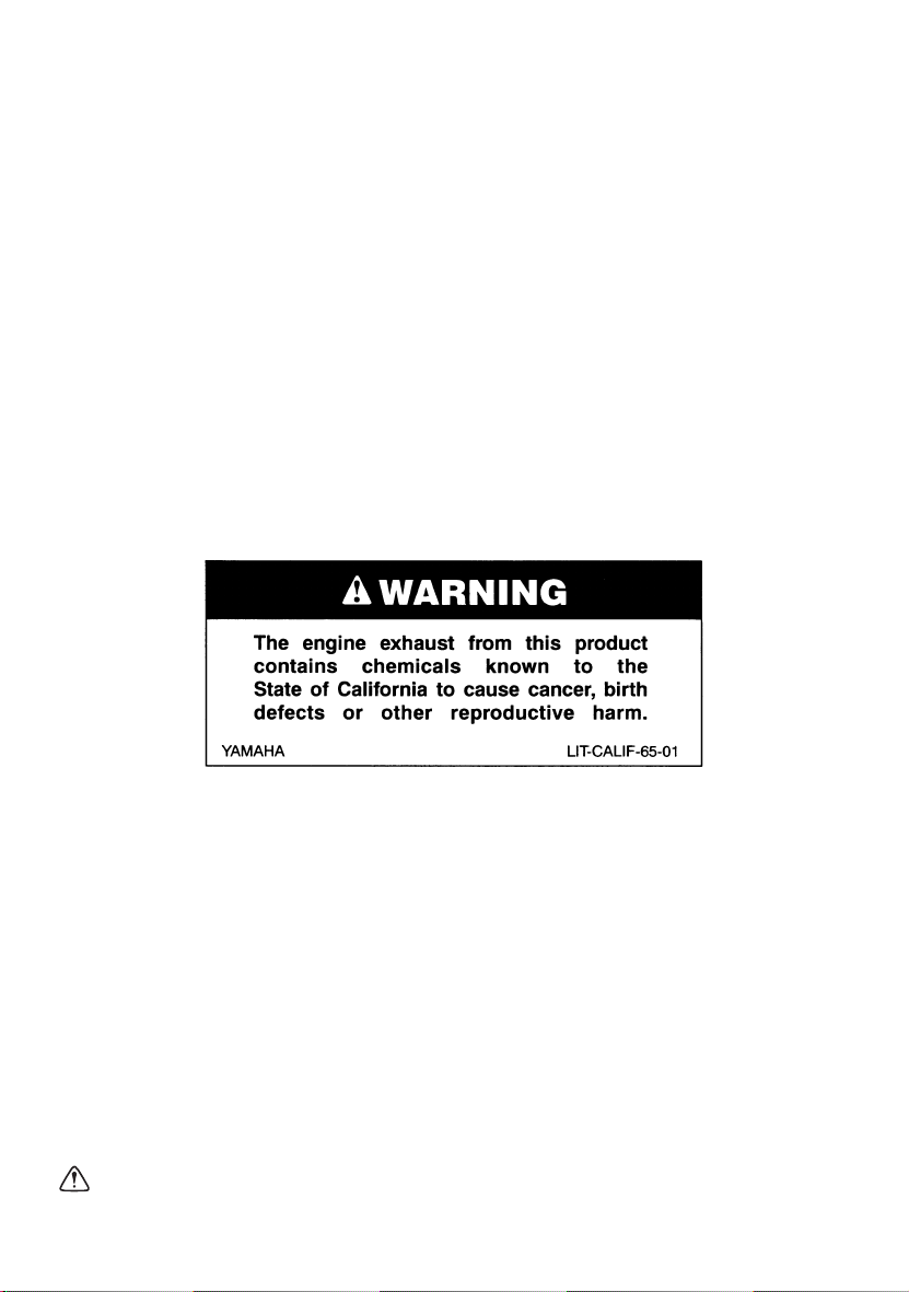
EWS00670
WARNING
Please read this manual carefully before
operating this snowmobile. Do not attempt
to operate this snowmobile until you have
attained adequate knowledge of its controls and operating features.
Regular inspections and careful maintenance, along with good operating techniques, will help ensure that you safely
enjoy the capabilities and reliability of this
snowmobile.
Introduction
RX10RZ
RX10LTZ
RX10MTZ
OWNER’S MANUAL
©2009 by Yamaha Motor Corporation,
U.S.A.
1st Edition, July 2009
All rights reserved.
Any reprinting or unauthorized use
without the written permission of
Yamaha Motor Corporation, U.S.A.
is expressly prohibited.
Printed in Japan.
P/N LIT-12628-02-88
Important manual information
ESU10151
Particularly important information is distinguished in this manual by the following notations.
This is the safety alert symbol. It is used
to alert you to potential personal injury hazards. Obey all safety messages that follow
this symbol to avoid possible injury or death.
EWS00021
WARNING
A WARNING indicates a hazardous situation which, if not avoided, could result in
death or serious injury.
ECS00011
NOTICE
A NOTICE indicates special precautions
that must be taken to avoid damage to the
snowmobile or other property.
TIP
A TIP provides key information to make procedures easier or clearer.

Contents
Location of the important labels ..... 1
Safety information ............................ 6
Description ........................................ 8
Control functions ............................ 11
Main switch .................................. 11
Throttle lever ................................ 11
Throttle override system
(T.O.R.S.) .................................. 11
Multi-function meter unit ............... 12
High beam indicator light .............. 14
Low coolant temperature indicator
light ............................................ 14
Fuel meter and grip/thumb
warmer level indicator ............... 14
Fuel level warning indicator .......... 16
Oil level warning indicator ............ 16
Coolant temperature warning
indicator ..................................... 17
Self-diagnosis device ................... 17
Engine stop switch ....................... 17
Headlight beam switch
“LIGHTS” ................................... 18
Grip/thumb warmer adjustment
switch ........................................ 18
Auxiliary DC jack .......................... 18
Helmet shield heater jack
(RX10R / RX10LT) .................... 19
Brake lever ................................... 19
Parking brake lever ...................... 20
Shift lever ..................................... 20
Shroud and covers ....................... 21
Drive guard ................................... 21
V-belt holders ............................... 23
Storage compartment ................... 23
Rear carrier (RX10MT) ................. 23
Fuel .............................................. 23
Suspension .................................. 24
Pre-operation checks ..................... 31
Pre-operation check list ............... 31
Operation ......................................... 33
Starting the engine ....................... 33
Break-in ........................................ 34
Riding your snowmobile ............... 34
Maximizing drive track life ............ 38
Strap (RX10MT) ........................... 39
Driving .......................................... 39
Stopping the engine ..................... 40
Transporting ................................. 40
Periodic maintenance and
adjustment....................................... 42
Periodic maintenance chart for
the emission control system ..... 42
General maintenance and
lubrication chart ........................ 44
Tool kit ......................................... 46
Removing and installing the
shroud and covers .................... 46
Checking the spark plugs ............. 48
Adjusting the engine idling
speed ........................................ 49
Adjusting the throttle cable free
play ........................................... 50
Checking the throttle override
system (T.O.R.S.) ..................... 51
Checking the air filter ................... 51
High-altitude settings ................... 53
Valve clearance ........................... 53
Engine oil and oil filter cartridge ... 53
Cooling system ............................ 57
V-belt ............................................ 59
Drive chain housing ..................... 61
Brake and parking brake .............. 63
Extrovert drive sprocket ............... 65
Skis and ski runners ..................... 65
Steering system ........................... 66
Drive track and slide runners ....... 66
High-profile pattern drive track ..... 71

Contents
Lubrication .................................... 71
Replacing a headlight bulb ........... 72
Adjusting the headlight beams ..... 73
Fittings and fasteners ................... 74
Battery .......................................... 74
Replacing a fuse .......................... 74
Troubleshooting ............................. 78
Storage ............................................ 82
Specifications ................................. 84
Consumer information.................... 86
Identification number records ....... 86
Vehicle Emission Control
Information label ........................ 87
YAMAHA MOTOR
CORPORATION, U.S.A.
SNOWMOBILE LIMITED
WARRANTY............................... 88
YAMAHA EXTENDED SERVICE
(Y.E.S.)....................................... 91
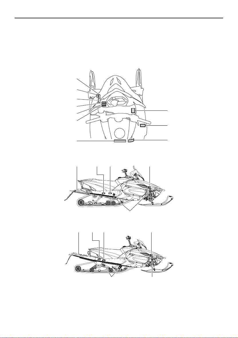
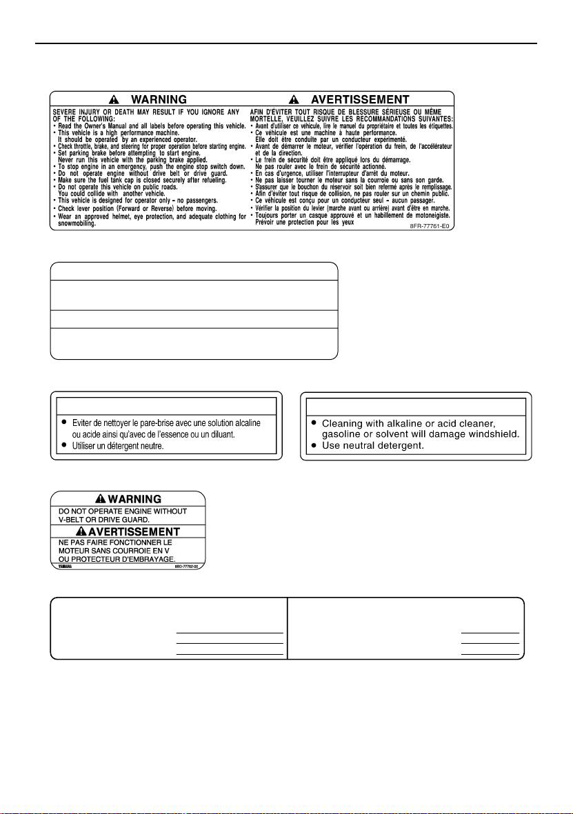
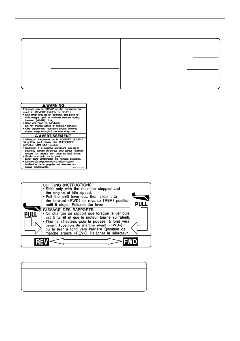
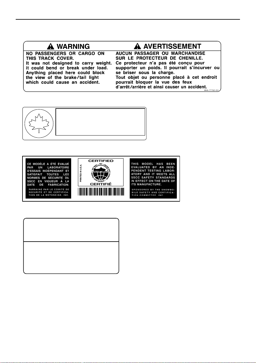
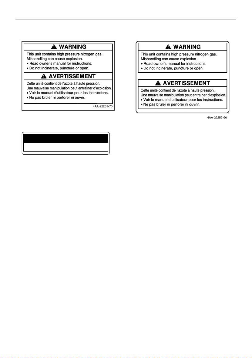
Location of the important labels
ESU10215
Read and understand all of the labels on your vehicle. They contain important information for
safe and proper operation of your vehicle. Never remove any labels from your vehicle. If a label
becomes difficult to read or comes off, a replacement label is available from your Yamaha dealer.
7
6
5
4
3
2
8
9
1
RX10R/RX10LT
11
12 13 14
15
RX10MT
17 13 12 14
16 15
10
1
Location of the important labels
1
2 RX10R/RX10LT
NOTICE
Do not exceed the combined maximum capacity of
30W for the auxiliary jacks.
ATTENTION
Ne pas dépasser la capacité totale de 30W
des prises pour accessoires combinées.
8FR-2815S-E0
3
ATTENTION
5
6
TUNE-UP SPECIFICATIONS
ENGINE
1.SPARK PLUG
2.SPARK PLUG GAP
3.IDLE SPEED
8ET-2815K-10
CR9EB(NGK)
0.7 ~ 0.8 mm (0.028 ~ 0.031 in)
1500 ± 100 r/min
4
NOTICE
8ET-2815K-00
SPECIFICATIONS DE LA MISE AU POINT
MOTEUR
1.TYPE DE BOUGIE
2.ECARTEMENT DES ÉLECTRODES
3.RÉGIME DE RALENTI
CR9EB(NGK)
0.7 ~ 0.8 mm
1500 ± 100 r/min
8FP-1417E-01
8FP
2
Location of the important labels
7
TUNE-UP SPECIFICATIONS
DRIVE
1. CHAIN CASE OIL Q’TY
2. CHAIN CASE OIL TYPE
3. TRACK TENSION
* FOR MORE INFO: SEE SERVICE MANUAL FOR THIS
MODEL.
* SPECIFICATIONS SUBJECT TO CHANGE WITHOUT
NOTICE.
30 ~ 35 mm (1.18 ~ 1.38 in)/100 N (10 kg, 22 lb)
8 RX10MT
9
250 cm³ (8.5 oz)
GL-3 75W or 80W
SPECIFICATIONS DE LA MISE AU POINT
ENTRAÎNEMENT
1. CAPACITÉ D’HUILE DU CARTER DE CHAÎNE
2. TYPE D’HUILE DU CARTER DE CHAÎNE
3. FLÈCHE DE LA CHENILLE
* POUR PLUS DE DÉTAIL: VOIR LE MANUEL D’ATELIER
POUR CE MODÈLE.
* LES CARACTÉRISTIQUE TECHNIQUES SONT
SUSCEPTIBLES DE CHANGER SANS NOTIFICATION
PRÉALABLE.
8FR-77763-E0
250 cm³
GL-3 75W or 80W
30 ~ 35 mm/100 N (10 kg)
8ES-47578-00
10 RX10MT
NOTICE ATTENTION
This snowmobile is originally equipped with
a 57mm (2.25in.) high-profile pattern track
for deep snow riding conditions.
Operation on light snowfall, ice, hard-packed
snow, dirt, etc., will result in rapid wear or
damage to track and slide runners.
Cette motoneige est équipée d’une chenille
à relief de 57 mm (2,25 po) pour la neige profonde.
La conduite sur de la neige peu profonde,
de la glace, de la neige tassée, de la saleté, etc.
provoquera une usure rapide ou l’endommagement
de la chenille et des patins.
8HR-2815M-E0
3
Location of the important labels
11 RX10LT
12
A
D
N
A
13
A
C
•
S
S
V
506
M
C
•
T
R
A
N
This spark ignition system meets all requirements of the
•
N
Canadian Interference Causing Equipment Regulations.
S
V
A
C
Ce système d’allumage par étincelle de véhicule
•
respecte toutes les exigences du Règlement sur le
T
matériel brouilleur du Canada.
R
O
P
S
3JK-82377-10
14
JUMPER CABLE CONNECTION LEADS
• For connecting procedures, refer to
Owner’s Manual.
FILS DE BRANCHEMENT DES CÂBLES
DE DÉMARRAGE
•
Effectuer le branchement des câbles
de démarrage conformément aux
instructions du Manuel du propriétaire.
8FA-2389C-E0
4
88C-77769-00
8FA-E0
Location of the important labels
15
17 RX10MT
LOAD LIMIT / CHARGE LIMITE
10kg {22lbs}
8ET-24897-00
16 RX10MT
5
Safety information
ESU10183
As the vehicle’s owner, you are responsible
for the safe and proper operation of your
snowmobile. When you ride your snowmobile, you must know and use the following for
your safety. Severe injury or death may result
if you ignore any of the following.
Before you operate your snowmobile
● Read the Owner’s Manual and all labels.
Become familiar with all of the operating
controls and their function. Consult a
Yamaha dealer about any control or func-
tion you do not understand.
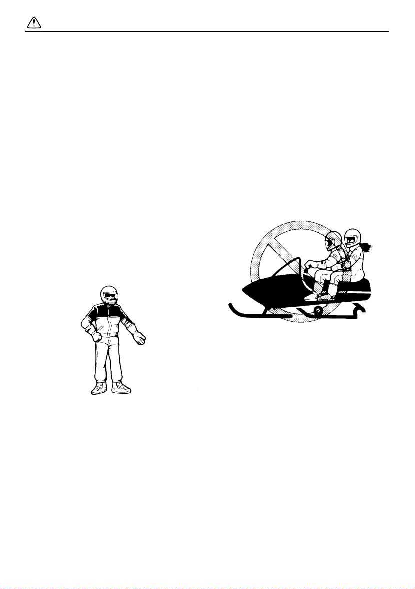
● Wear protective clothing. Wear an ap-
proved helmet, and a face shield or goggles. Also, wear a good quality snowmobile
suit, boots, and a pair of gloves or mittens
that will permit use of your thumbs and fingers for operation of the controls.
● Apply the parking brake before starting the
engine. Never drive the snowmobile with
the parking brake applied. This may overheat the brake disc and reduce braking ability.
While using your snowmobile
● This snowmobile was not manufactured for
use on public streets, roads, or highways.
Such use is prohibited by law, and you
could collide with another vehicle.
● This snowmobile is designed to carry the
OPERATOR ONLY. Passengers are prohibited. Carrying a passenger can cause
loss of control.
● Do not operate the snowmobile after or
while drinking alcohol or taking drugs. Your
ability to operate the snowmobile is reduced by the influence of alcohol or drugs.
Prepare your snowmobile
● Perform the pre-operation checks each
time you use the vehicle to make sure it is
in safe operating condition. Failure to inspect or maintain the vehicle properly increases the possibility of an accident or
equipment damage. See page 31 for a list
of pre-operation checks.
6
● Be careful where you ride. There may be
obstacles hidden beneath the snow. Stay
on established trails to minimize your exposure to hazards. Ride slowly and cautiously
when you ride off of established trails. Hitting a rock or stump, or running into wires
could cause an accident and injury.
● This snowmobile is not designed for use on
surfaces other than snow or ice. Use on dirt,
sand, grass, rocks, or bare pavement may
cause loss of control and may damage the
snowmobile.
● Always ride with other snowmobilers when
going on a ride. You may need help if you
run out of fuel, have an accident, or damage
your snowmobile.

Safety information
● Many surfaces such as ice and hardpacked
snow require much longer stopping distances. Be alert, plan ahead and begin decelerating early. The best braking method on
most surfaces is to release the throttle and
apply the brake gently—not suddenly.
Avoid carbon monoxide poisoning
All engine exhaust contains carbon monoxide, a deadly gas. Breathing carbon monoxide
can cause headaches, dizziness, drowsiness,
nausea, confusion, and eventually death.
Carbon monoxide is a colorless, odorless,
tasteless gas which may be present even if
you do not see or smell any engine exhaust.
Deadly levels of carbon monoxide can collect
rapidly and you can quickly be overcome and
be unable to save yourself. Also, deadly levels of carbon monoxide can linger for hours or
days in enclosed or poorly-ventilated areas. If
you experience any symptoms of carbon
monoxide poisoning, leave the area immediately, get fresh air, and SEEK MEDICAL
TREATMENT.
● Do not run the engine indoors. Even if you
try to ventilate engine exhaust with fans or
open windows and doors, carbon monoxide
can rapidly reach dangerous levels.
● Do not run the engine in poorly ventilated or
partially enclosed areas such as barns, garages, or carports.
● Do not run the engine outdoors where en-
gine exhaust can be drawn into a building
through openings such as windows and
doors.
Genuine Yamaha Accessories
Choosing accessories for your snowmobile is
an important decision. Genuine Yamaha Accessories, which are available only from a
Yamaha dealer, have been designed, tested,
and approved by Yamaha for use on your
snowmobile. Many companies with no connection to Yamaha manufacture parts and ac-
cessories or offer other modifications for
Yamaha vehicles. Yamaha is not in a position
to test the products that these aftermarket
companies produce. Therefore, Yamaha can
neither endorse nor recommend the use of
accessories not sold by Yamaha or modifications not specifically recommended by
Yamaha, even if sold and installed by a
Yamaha dealer.
Maintenance and storage
● When laying the snowmobile on its side for
maintenance, use a suitable stand to keep
it in a stable and level position.
● Do not leave the snowmobile on its left side
for an extended period of time. Fuel may
leak out from the fuel breather hose.
● Do not allow anyone to stand behind the
snowmobile when starting, inspecting, or
adjusting the snowmobile. A broken track,
track fittings, or debris thrown by the track
could be dangerous to the operator or bystanders.
● Modifications made to the snowmobile not
approved by Yamaha, or the removal of
original equipment may render your snowmobile unsafe for use, which may cause severe personal injury. Modifications may
also make the snowmobile illegal to use.
● Never store the snowmobile with fuel in the
fuel tank inside a building where ignition
sources are present such as hot water and
space heaters, an open flame, sparks,
clothes dryers, and the like. Allow the engine to cool off before storing the snowmobile in an enclosed space.
7
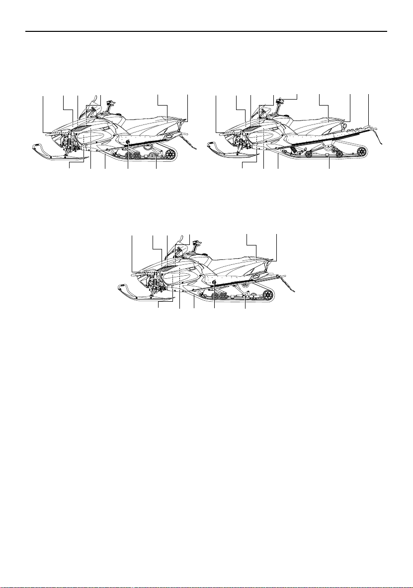
Description
ESU10260
RX10R
34
5,6,7
9,10
131516
1417
111,2
RX10LT
5,6,734
1. Battery
2. Main fuse
3. Air filter
4. Oil filler cap
5. Fuse box
6. Coolant reservoir
7. Coolant recovery tank
8. Strap (RX10MT)
9. Tool kit
10. Storage compartment
11. Tail/brake light
12. Rear carrier (RX10MT)
13. Slide rail suspension
14. Rear shock absorber damping force remote
adjusting dial (RX10R / RX10LT)
15. Drive track
16. Idle adjusting screw
17. V-belt holder
RX10MT
17
9,10
1417
131516
5,6,734
9,10
8
12
111,2
131516
111,2
8
1
23 4567 8
11
10
9
12 13 14 15
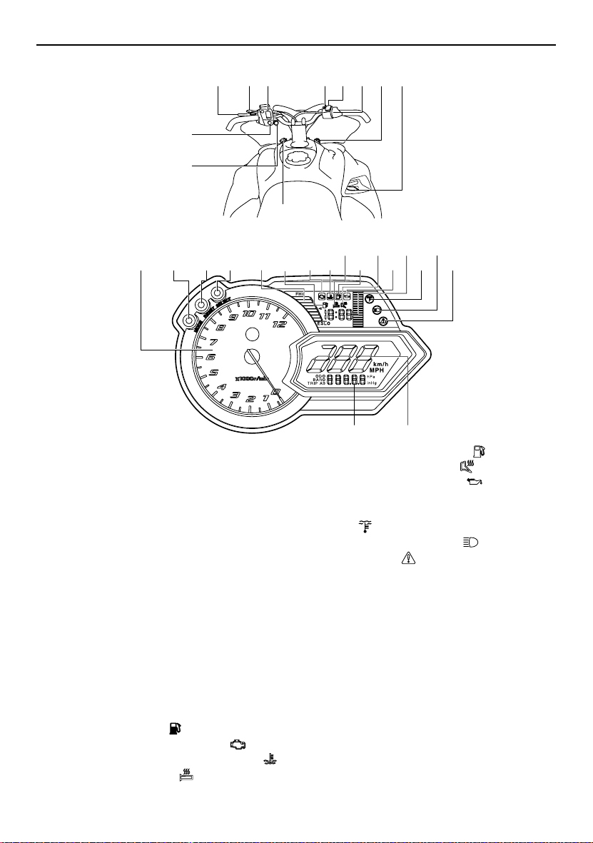
1. Brake lever
2. Parking brake lever
3. Grip warmer adjustment switch
4. Engine stop switch
5. Thumb warmer adjustment switch
6. Throttle lever
7. Main switch
8. Shift lever
9. Auxiliary DC jack
10. Helmet shield heater jack (RX10R /
RX10LT)
11. Headlight beam switch
12. Tachometer
13. “MODE” button
14. “RESET” button
15. “SELECT” button
16. Fuel meter and grip/thumb warmer level indicator
17. Fuel meter indicator “”
18. Self-diagnosis warning indicator “”
19. Coolant temperature warning indicator “”
20. Grip warmer indicator “”
16 18 19 21 23 25 2717
Description
20 22 24 26
2829
21. Fuel level warning indicator “”
22. Thumb warmer indicator “”
23. Oil level warning indicator “”
24. Clock
25. Low coolant temperature indicator
light “”
26. High beam indicator light “”
27. Warning light “”
28. Speedometer
29. Odometer/tripmeter/barometer
9

Description
TIP
● The snowmobile you have purchased may differ slightly from those shown in the figures of
this manual.
● Design and specifications are subjected to change without notice.
10
ESU10292
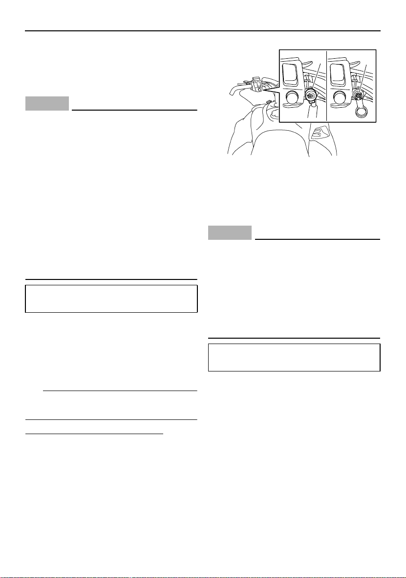
Main switch
The main switch controls the ignition and
lighting systems. The various positions are
described below.
2
13
1. Off
2. On
3. Start
Off
The ignition circuit is switched off.
The key can be removed only in this position.
On
The ignition circuit is switched on.
Start
The starting circuit is switched on.
The starter motor cranks the engine.
NOTICE: Release the switch immediately
after the engine starts.
[ECS00021]
TIP
The headlights and taillight come on after the
engine is started.
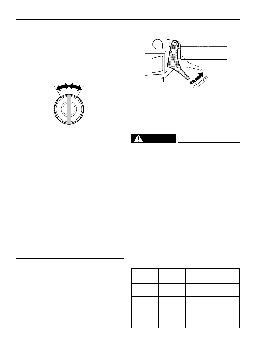
ESU10312
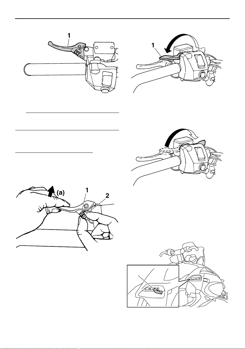
Throttle lever
Once the engine is running cleanly, squeezing the throttle lever will increase the engine
speed and cause engagement of the drive
train. Regulate the speed of the snowmobile
by varying the throttle position. Because the
throttle is spring-loaded, the snowmobile will
decelerate, and the engine will return to idle
when it is released.
Control functions
1. Throttle lever
ESU10346
Throttle override system (T.O.R.S.)
EWS00041
WARNING
If the T.O.R.S. is activated, make sure that
the cause of the malfunction has been corrected and that the engine can be operated
without a problem before restarting the
engine. Continuing to operate with a malfunction could cause loss of control or
damage.
If the throttle valves or throttle cable malfunctions during operation, the T.O.R.S. will be activated when the throttle lever is released.
The T.O.R.S. is designed to override the fuel
injection and limit the engine speed to less
than the clutch engagement speed if the throttle valves fail to return to the idle position
when the throttle lever is released. (See page
84 for the clutch engagement speed.)
Malfunc-
tion
T. O. R .S .
will be ac-
tivated.
Throttle
lever
Throttle
valve
T.O. R.S.
Idling Riding
Released Squeezed Released
Closed Open Open
Engine
runs
properly.
Engine
runs
properly.
11
Control functions
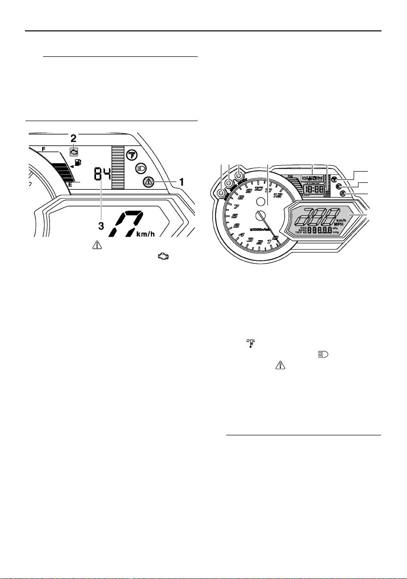
TIP
If the T.O.R.S. is activated, the warning light
and self-diagnosis warning indicator will flash,
and the two-digit code “84” will flash in the
meter display. If this occurs, have a Yamaha
dealer check the system as soon as possible.
1. Warning light “”
2. Self-diagnosis warning indicator “”
3. Two-digit code “84”
ESU10364
Multi-function meter unit
The multi-function meter unit is equipped with
the following:
● a digital speedometer
● a tachometer
● an odometer
● two tripmeters (which show the distance
traveled since they were last set to zero)
● a barometer (which shows the ambient
barometric pressure)
● a clock
● warning indicators (which show self-diag-
nosis, coolant temperature, fuel level, and
oil level warnings)
● indicator lights (which show high beam and
low coolant temperature conditions)
● a warning light (which shows warnings to-
gether with the warning indicators)
● a fuel meter (which shows the fuel remain-
ing in the fuel tank)
● a grip/thumb warmer level indicator (which
shows the grip warmer level or the thumb
warmer level)
● a display brightness control function
When the key is turned to the on position, the
tachometer needle makes one sweep, and
the low coolant temperature indicator light,
the warning light, and all segments of the
meter unit display come on and go off.
12 3 5 6
4
7
8
9
10
1. “MODE” button
2. “RESET” button
3. “SELECT” button
4. Tachometer
5. Warning indicators
6. Clock
7. Low coolant temperature indicator
light “”
8. High beam indicator light “”
9. Warning light “”
10. Meter display
The grip warmer level is initially displayed for
5 seconds, then the display switches to the
fuel meter.
TIP
● To switch the speedometer, odometer, and
tripmeter displays between kilometers and
miles, select the odometer mode “ODO”,
and then push the “SELECT” button for at
least 10 seconds while the snowmobile is
stopped.
● To switch the barometer display between
hectopascal “hPa” and inches of mercury
“inHg”, select the barometer mode “BARO”,
12
Control functions
and then push the “SELECT” button for at
least 3 seconds while the snowmobile is
stopped.
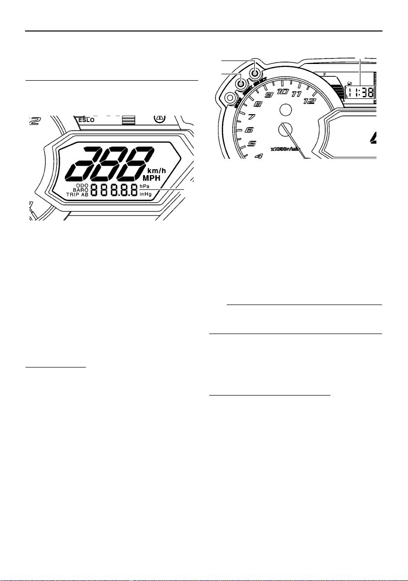
Odometer, tripmeter, and barometer
modes
1
1. Odometer/tripmeter/barometer
Pushing the “SELECT” button switches the
display between the odometer mode “ODO”,
tripmeter modes “TRIP A” and “TRIP B”, and
barometer mode “BARO” in the following order:
ODO → TRIP A → TRIP B → BARO → ODO
To reset a tripmeter, push the “RESET” button
for at least 1 second while the tripmeter is displayed.
Clock
To set the clock
1. Push the “SELECT” button and “RESET”
button simultaneously until the hour digits
start flashing.
1
3
2
1. “SELECT” button
2. “RESET” button
3. Clock
2. Push the “RESET” button to change the
hour setting, and then push the “SE-
LECT” button. The minute digits will start
flashing.
3. Push the “RESET” button to change the
minute setting, and then push the “SE-
LECT” button. The clock starts when the
“SELECT” button is released.
TIP
The clock must be set again when the battery
is disconnected.
Display brightness control
This function allows you to adjust the brightness of the meter display to suit the outdoor
lighting conditions.
To adjust the display brightness
1. Turn the main switch to the off position.
2. Push and hold down the “SELECT” button.
13
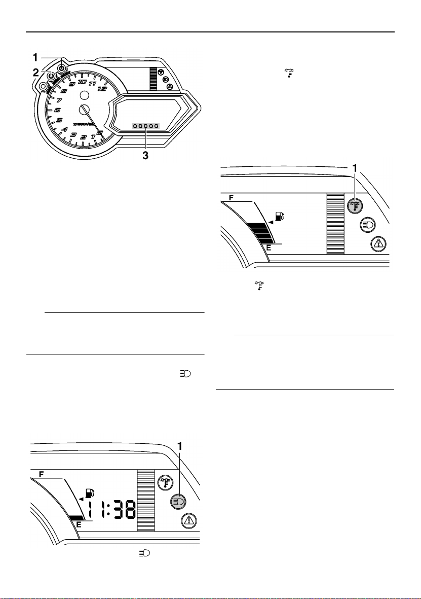
Control functions
1. “SELECT” button
2. “RESET” button
3. Display brightness level
3. Turn the main switch to the on position,
and then, after 5 seconds, release the
“SELECT” button.
4. Push the “RESET” button to select the
desired display brightness level, and then
push the “SELECT” button. The normal
display returns when the “SELECT” button is released.
TIP
If the main switch is turned to the off position
or the engine is started before completing the
procedure, the setting is not applied.
ESU10410
High beam indicator light “”
The high beam indicator light comes on when
the high beams of the headlights are switched
on. (See page 18 for headlight beam switch
operation.)
ESU10472
Low coolant temperature indicator light “”
The low coolant temperature indicator light
comes on when the coolant temperature is
low and informs the rider that the snowmobile
should be warmed up. After the engine is
started, warm it up until the indicator light
goes off.
1. Low coolant temperature indicator
light “”
The snowmobile can be operated normally after the indicator light goes off.
TIP
Drive the snowmobile at low speeds when the
low coolant temperature indicator light is on. If
the engine speed is too high, maximum engine speed is reduced to protect the engine.
ESU10424
Fuel meter and grip/thumb warmer level indicator
The fuel meter and grip/thumb warmer level
indicator have eight segments which show
the amount of fuel remaining in the fuel tank,
the grip warmer level, or the thumb warmer
level.
1. High beam indicator light “”
14
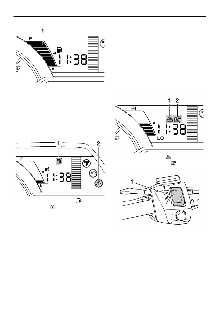
1. Fuel meter and grip/thumb warmer level indicator
Fuel meter
The display segments of the fuel meter disappear towards “E” (Empty) as the fuel level decreases. When only one segment is left near
“E”, the fuel level warning indicator and the
warning light come on.
Control functions
Grip/thumb warmer level indicator
When the grip warmer adjustment switch is
pressed, the grip warmer indicator comes on
and the display switches to the grip warmer
level.
When the thumb warmer adjustment switch is
pressed, the thumb warmer indicator comes
on and the display switches to the thumb
warmer level.
See “Grip/thumb warmer adjustment switch”
on page 18 for detailed information.
1. Grip warmer indicator “”
2. Thumb warmer indicator “”
1. Fuel level warning indicator “”
2. Warning light “”
If the fuel level warning indicator and the
warning light come on, refuel as soon as possible.
TIP
The snowmobile must be stopped on a level
surface to obtain an accurate fuel meter reading, since the reading changes according to
the movement and inclination of the snowmobile.
1. Grip warmer adjustment switch
15
Control functions
1. Thumb warmer adjustment switch
TIP
● The grip/thumb warmer level is displayed
for 5 seconds after releasing the grip/thumb
warmer adjustment switch, then the display
switches to the fuel meter.
● The top segment of the grip/thumb warmer
level indicator flashes once when the
grip/thumb warmer adjustment reaches the
maximum level. The bottom segment of the
grip/thumb warmer level indicator flashes
once when the grip/thumb warmer adjustment reaches the minimum level.
● When the engine is started, the grip/thumb
warmer levels are set to the levels selected
when the engine was last stopped.
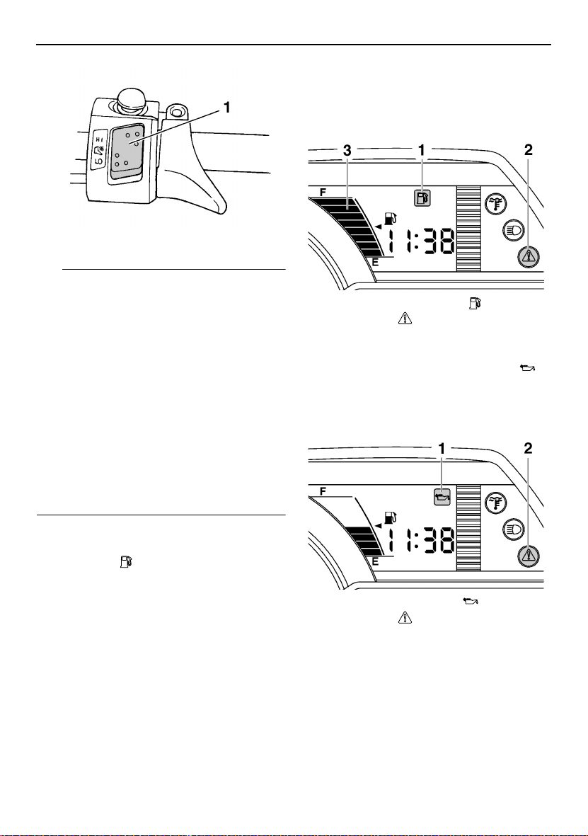
ESU10455
Fuel level warning indicator “”
The fuel level warning indicator and the warning light come on when the fuel level is low.
(See page 14 for details.)
The fuel level warning indicator, the warning
light, and all segments of the fuel meter start
to flash when a malfunctioning sensor, disconnected coupler, broken lead, or short circuit is detected by the self-diagnosis device of
the snowmobile to warn the rider of any of the
above problems.
If the fuel level warning indicator, the warning
light, and all segments of the fuel meter flash,
have a Yamaha dealer inspect the snowmobile as soon as possible.
1. Fuel level warning indicator “”
2. Warning light “”
3. Fuel meter
ESU10461
Oil level warning indicator “”
The oil level warning indicator and the warning light come on when the engine oil level is
low.
1. Oil level warning indicator “”
2. Warning light “”
If the oil level warning indicator and the warning light come on, place the snowmobile on a
level surface and allow it to idle for one
minute.
If the oil level warning indicator and the warning light go off, the engine oil level is sufficient,
however it is getting low. Add engine oil as
soon as possible.
16
Control functions
If the oil level warning indicator and the warning light do not go off, check the engine oil level in the oil tank (see page 53 for engine oil
level checking procedures), and add engine
oil if necessary.
If the oil level warning indicator and the warning light still remain on, have a Yamaha dealer
check the snowmobile.
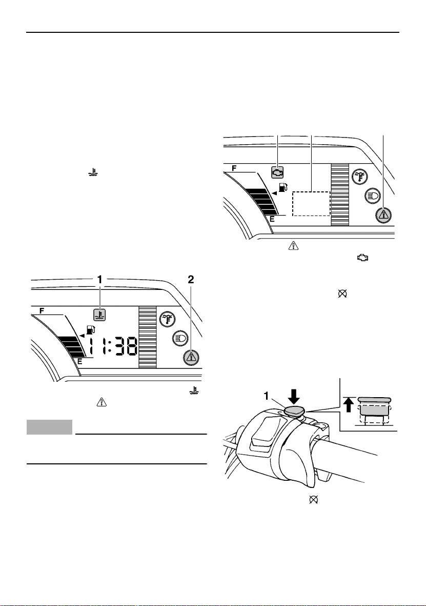
ESU10512
Coolant temperature warning indicator “”
If the engine overheats, the coolant temperature warning indicator and the warning light
come on. When this occurs, stop the engine
immediately and allow the engine to cool
down, and then check the coolant level in the
coolant reservoir. (See page 57 for checking
procedures.)
error code, and then have a Yamaha dealer
inspect the snowmobile as soon as possible.
NOTICE: Do not continue to operate the
engine longer than necessary if there is an
error code to avoid possible engine damage.
[ECS00820]
32 1
1. Warning light “”
2. Self-diagnosis warning indicator “”
3. Error code display
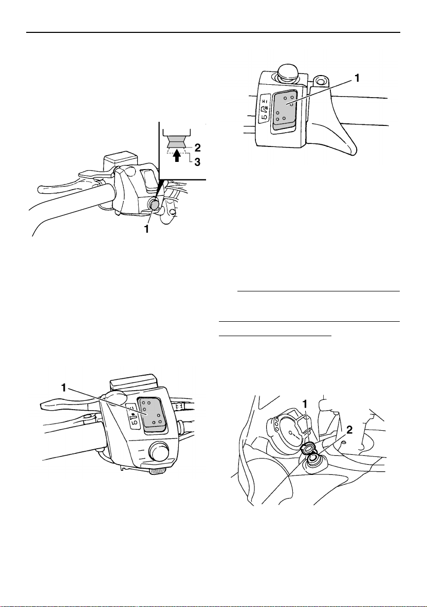
ESU10531
Engine stop switch “”
The engine stop switch is used to stop the engine in an emergency. Simply push the stop
switch to stop the engine. To start the engine,
pull the stop switch and proceed with starting
the engine. (See page 33 for engine starting
procedures.)
1. Coolant temperature warning indicator “”
2. Warning light “”
ECS00041
NOTICE
Do not continue to operate the engine if it
is overheating.
ESU12685
Self-diagnosis device
This model is equipped with a self-diagnosis
device for various electrical circuits.
If a problem is detected in any of those circuits, the warning light and the self-diagnosis
warning indicator flash, and an error code
flashes slowly in the meter display. Note the
1. Engine stop switch “”
During the first few rides, practice using the
stop switch so that you can react quickly in an
emergency.
17
Control functions
ESU10661
Headlight beam switch
“LIGHTS”
Push the headlight beam switch to change the
headlight to high beam “HI” or to low beam
“LO”.
1. Headlight beam switch “LIGHTS”
2. High beam “HI”
3. Low beam “LO”
ESU12651
Grip/thumb warmer adjustment switch
The grip warmer adjustment switch and the
thumb warmer adjustment switch control the
electrically heated handlebar grips and throttle lever respectively.
1. Thumb warmer adjustment switch
To raise the temperature, press the respective switch to “HI”. To lower the temperature,
press the switch to “LO”. (See page 14 for
more information.)
ESU13683
Auxiliary DC jack
The auxiliary DC jack is located in the front
panel and can be used for accessories.
TIP
The auxiliary DC jack can only be used if the
engine is running.
To use the auxiliary DC jack
1. Start the engine.
2. Open the auxiliary DC jack cap, and then
insert the accessory power plug into the
jack.
1. Grip warmer adjustment switch
18
1. Auxiliary DC jack cap
2. Auxiliary DC jack
3. After using the auxiliary DC jack, be sure
to remove the accessory power plug from
the jack and to close the auxiliary DC jack
cap.
ECS01002
NOTICE
● To avoid circuit overload and a possible
fuse blowing, do not use accessories requiring more than the maximum rated
capacity for the auxiliary DC jack.
RX10R / RX10LT: Do not connect accessories with a combined requirement of
more than 30 W to the auxiliary DC jack
and helmet shield heater jack.
(See page 74 for the specified fuse amperage.)
● Do not use an automotive cigarette light-
er or other accessory with a plug that
gets hot because the jack can be damaged.
Maximum rated capacity:
DC 12 V, 2.5 A (30 W)
ESU13690
Helmet shield heater jack
(RX10R / RX10LT)
The helmet shield heater jack is located on
the left side of the handlebar.
TIP
The helmet shield heater jack can only be
used if the engine is running.
To use the helmet shield heater jack
1. Start the engine.
2. Open the helmet shield heater jack cap,
and then insert the power plug of the helmet shield heater into the jack.
Control functions
1
1. Helmet shield heater jack cap
2. Helmet shield heater jack
3. After using the helmet shield heater, be
sure to remove its power plug from the
jack and to close the jack cap.
ECS01010
NOTICE
To avoid circuit overload and a possible
fuse blowing, do not use a helmet shield
heater requiring more than the maximum
rated capacity for the helmet shield heater
jack and, when using both the auxiliary DC
jack and helmet shield heater jack, do not
use accessories requiring a combined total of more than 30 W.
Maximum rated capacity:
DC 12 V, 1.5 A (18 W)
ESU13522
Brake lever
The snowmobile is stopped by braking the entire drive system.
Squeeze the brake lever towards the handlebar grip to stop the snowmobile.
2
19
Control functions
1. Brake lever
TIP
When the brake lever is squeezed, the brake
light comes on.
The brake lever is equipped with a position
adjuster.
To adjust the brake lever position:
1. Loosen the locknut.
2. While lightly pushing the brake lever in direction (a), turn the adjusting bolt to set
the brake lever to the desired position.
1. Locknut
2. Adjusting bolt
3. Tighten the locknut securely after adjusting the brake lever position.
ESU10581
Parking brake lever
When parking the snowmobile or starting the
engine, apply the parking brake by moving the
parking brake lever to the left.
1. Parking brake lever
To release the parking brake, move the parking brake lever to the right.
ESU10592
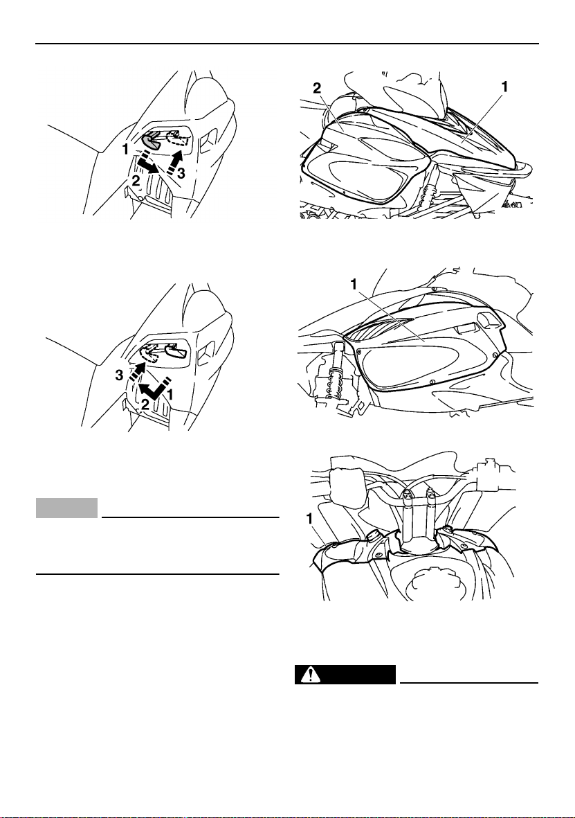
Shift lever
The shift lever is used to put the snowmobile
into forward or reverse. After coming to a
complete stop, pull the shift lever out, slide it
to “FWD” or to “REV” until it stops, and then
release it.
1
1. Shift lever
20
Control functions
1. Pull out.
2. Slide to “FWD” (forward).
3. Release.
1. Pull out.
2. Slide to “REV” (reverse).
3. Release.
ECS00072
NOTICE
Do not use the shift lever while the snowmobile is moving, otherwise the drive train
could be damaged.
ESU10722
Shroud and covers
Securely fasten the shroud and covers before
operating the snowmobile. (See page 46 for
removal and installation procedures.)
1. Shroud
2. Right side cover
1. Left side cover
1. Top cover
ESU13312
Drive guard
EWS00401
WARNING
● Coming in contact with the rotating V-
belt or clutch parts can cause severe injury or death. Never run the engine with
the drive guard removed.
21
Control functions
● Make sure that the drive guard is tight-
ened securely before operating the
snowmobile to protect against severe
injury or death from a broken V-belt or
other part should it come off the snowmobile while it is in operation.
ECS00930
NOTICE
● Never run the engine with the V-belt re-
moved. Clutch components can be damaged.
● Be careful not to scratch the windshield
when removing or installing the drive
guard.
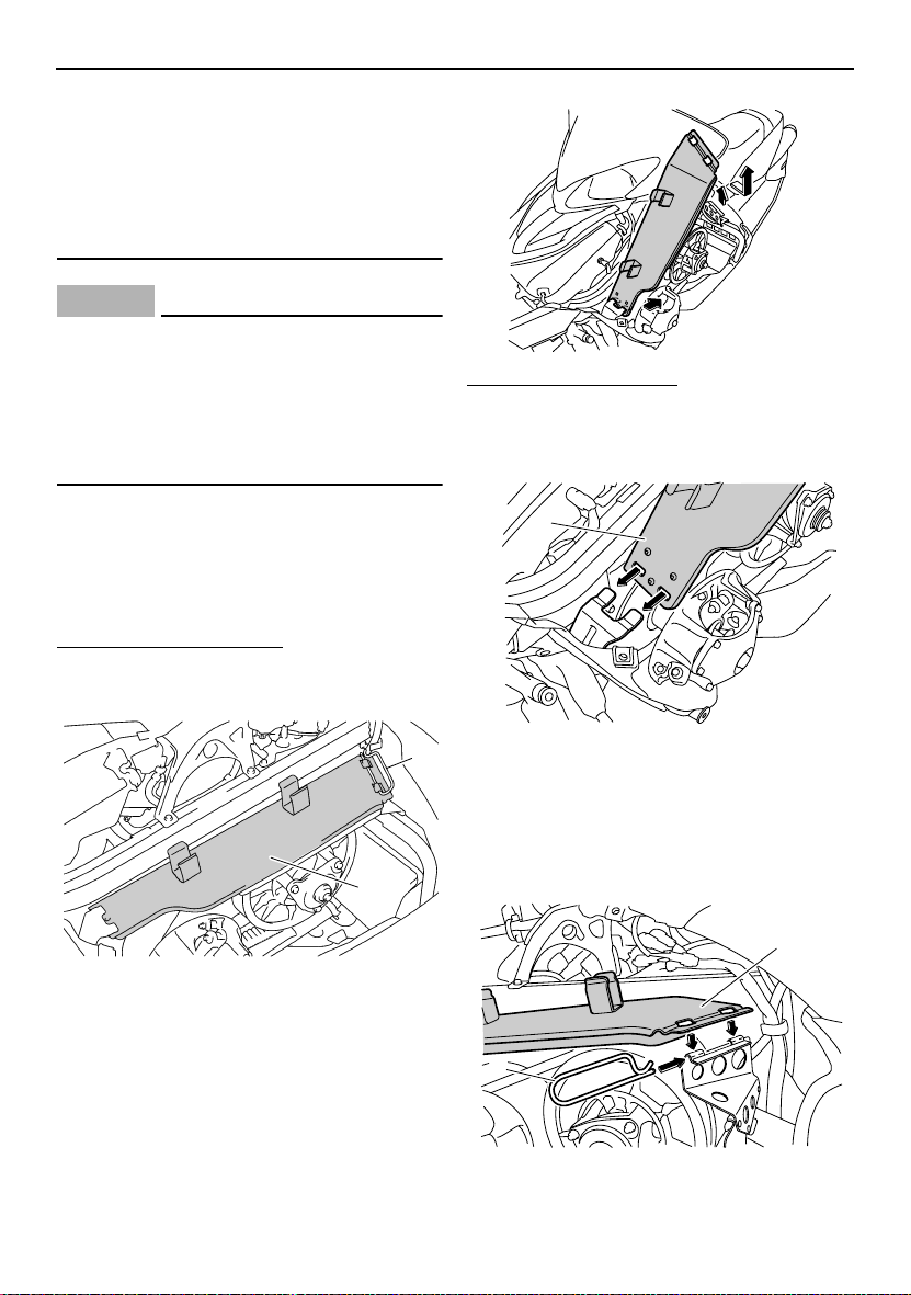
To install the drive guard
1. Fit the front slots in the drive guard over
the projections on the drive guard front
holder.
The drive guard is designed to protect the Vbelt clutch and V-belt in case parts break or
come loose.
The drive guard is located behind the left side
cover. (See page 46 for removal procedures.)
To remove the drive guard
1. Pull out the drive guard locking pin from
the drive guard rear holder.
2
1
1. Drive guard
2. Drive guard locking pin
2. Lift up the rear of the drive guard as
shown, and then pull the guard rearward
to remove it.
1
1. Drive guard
2. Align the slots in the rear of the drive
guard with the projections on the drive
guard rear holder, and then insert the
drive guard locking pin into the holder as
shown.
1
2
22
1. Drive guard
2. Drive guard locking pin
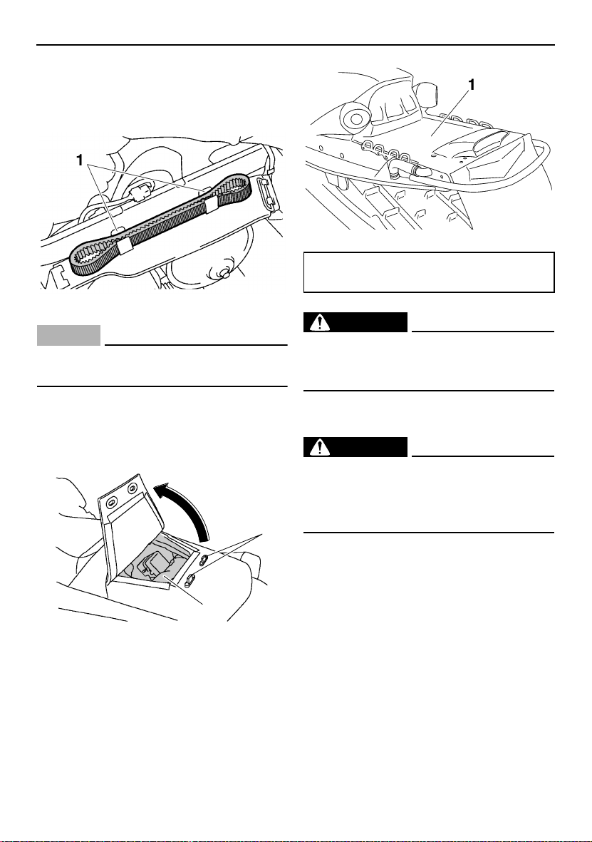
ESU10760
V-belt holders
Keep a spare V-belt for emergency use by
placing it into the V-belt holders provided.
1. V-belt holder
ECS00180
NOTICE
Make sure that the V-belt is installed securely in the holders.
ESU10810
Storage compartment
Open the storage compartment to store the
tool kit, spare parts, or other small items.
1
2
1. Fastener
2. Storage compartment
ESU10840
Rear carrier (RX10MT)
The rear carrier is located at the rear of the
snowmobile.
Control functions
1. Rear carrier
Maximum load limit:
10 kg (22 lb)
EWS00140
WARNING
Do not use the rear carrier to lift the snowmobile. The snowmobile could fall, which
could result in severe injury or death.
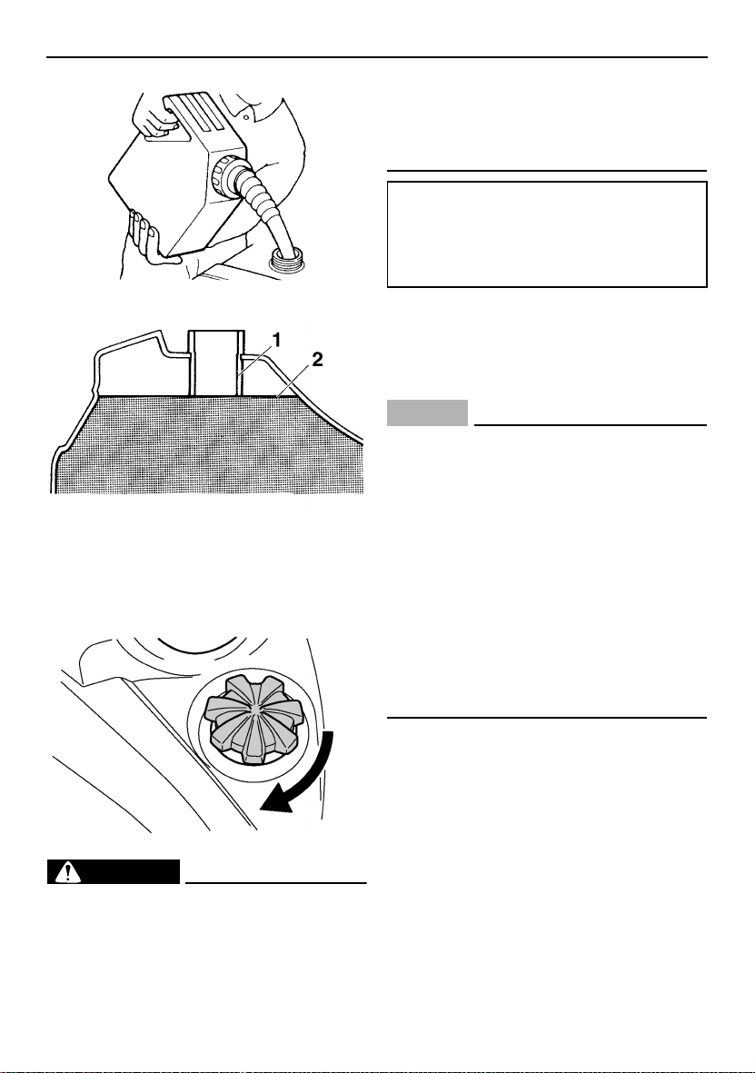
ESU10604
Fuel
EWS00071
WARNING
Gasoline and gasoline vapors are extremely flammable. To avoid fires and explosions and to reduce the risk of injury
when refueling, follow these instructions.
Make sure there is sufficient gasoline in the
tank.
1. Before refueling, turn off the engine and
be sure that nobody is on the snowmobile. Never refuel while smoking, or while
in the vicinity of sparks, open flames, or
other sources of ignition such as the pilot
lights of water heaters and clothes dryers.
2. Do not overfill the fuel tank. Stop filling
when the fuel reaches the bottom of the
filler tube. Because fuel expands when it
heats up, heat from the engine or the sun
can cause fuel to spill out of the fuel tank.
23
Control functions
1. Filler tube
2. Maximum fuel level
3. Wipe up any spilled fuel immediately.
4. Be sure the fuel tank cap is closed securely by turning it clockwise.
EWS00680
WARNING
Gasoline is poisonous and can cause injury or death. Handle gasoline with care.
Never siphon gasoline by mouth. If you
should swallow some gasoline or inhale a
lot of gasoline vapor, or get some gasoline
in your eyes, see your doctor immediately.
If gasoline spills on your skin, wash with
soap and water. If gasoline spills on your
clothing, change your clothes.
Recommended fuel:
REGULAR UNLEADED GASOLINE
ONLY
Fuel tank capacity:
35.6 L (9.41 US gal, 7.83 Imp.gal)
Your Yamaha engine has been designed to
use regular unleaded gasoline with a pump
octane number [(R+M)/2] of 86 or higher, or a
research octane number of 91 or higher.
ECS00082
NOTICE
● Oxygenated fuels (gasohol) containing
a maximum 5% of ethanol (E5) can be
used, although richer jetting may be required to prevent engine damage. Consult a Yamaha dealer. Gasohol
containing methanol is not recommended.
● Make sure that snow or ice does not en-
ter the fuel tank when refueling.
● Do not use alcohol deicers or water ab-
sorbing additives with oxygenated fuel.
● The fuel tank should be filled with the
recommended gasoline as specified.
ESU10873
Suspension
The suspension can be adjusted to suit rider
preference. Softer settings, for example, may
provide greater rider comfort, while harder
settings may allow more precise handling and
control over certain types of terrain or riding
conditions.
If you are not familiar with suspension adjustments, have a Yamaha dealer make these
adjustments.
24
 Loading...