

Page 1

OWNER’S MANUAL
MANUEL DU PROPRIÉTAIRE
BEDIENUNGSANLEITUNG
PW50(X)
5PG-28199-87
Page 2

PRINTED ON RECYCLED PAPER
PRINTED ON RECYCLED PAPER
IMPRIMÉ SUR PAPIER RECYCLÉ
IMPRIMÉ SUR PAPIER RECYCLÉ
AUF RECYCLINGPAPIER GEDRUCKT
AUF RECYCLINGPAPIER GEDRUCKT
YAMAHA MOTOR CO., LTD.
YAMAHA MOTOR CO., LTD.
PRINTED IN JAPAN
PRINTED IN JAPAN
2007.4–1.1×1 !
2007.4–1.1×1 !
(E, F, G)
(E, F, G)
Page 3

OWNER’S MANUAL
PW50(X)
5PG-28199-87-E0
Page 4

Page 5
INTRODUCTION
EAU41070
Congratulations on your purchase of the Yamaha PW50(X). This model is the result of Yamaha’s vast experience in the production of fine sporting, touring, and pacesetting racing machines. It represents the high degree of craftsmanship and reliability that have made Yamaha a leader in these fields.
This manual will give you an understanding of the operation, inspection, and basic maintenance of this motorcycle. If you
have any questions concerning the operation or maintenance of your motorcycle, please consult a Yamaha dealer.
The design and manufacture of this Yamaha motorcycle fully comply with the emissions standards for clean air applicable
at the date of manufacture. Yamaha has met these standards without reducing the performance or economy of operation of
the motorcycle. To maintain these high standards, it is important that you and your Yamaha dealer pay close attention to the
recommended maintenance schedules and operating instructions contained within this manual.
AN IMPORTANT SAFETY MESSAGE:
●
READ THIS MANUAL CAREFULLY AND COMPLETELY BEFORE OPERATING THIS MOTORCYCLE. MAKE SURE
YOU UNDERSTAND ALL INSTRUCTIONS.
●
PAY CLOSE ATTENTION TO THE WARNING AND CAUTION LABELS ON THE MOTORCYCLE.
●
NEVER OPERATE A MOTORCYCLE WITHOUT PROPER TRAINING OR INSTRUCTION.
●
WEIGHT OF THE RIDER SHOULD NOT EXCEED 25 kg (55 lb).
AN IMPORTANT NOTE TO PARENTS:
This motorcycle is not a toy. Before you let your child ride this motorcycle, you should understand the instructions and warnings in this Owner’s Manual. Then be sure your child understands and will follow them. Children differ in skills, physical abilities, and judgment. Some children may not be able to operate a motorcycle safely. Parents should supervise their child’s
use of the motorcycle at all times. Parents should permit continued use only if they determine that the child has the ability to
operate the motorcycle safely.
Page 6
INTRODUCTION
Your motorcycle was delivered with an adjustable speed limiter and power reduction plate. Yamaha recommends that all
beginners start off with the speed limiter adjusting screw turned in and the power reduction plate installed in the exhaust manifold to limit the power available while they learn. The limiter screw may be gradually turned out to increase maximum speed
as the beginner becomes more familiar with operating the motorcycle. Parents should decide when to adjust the motorcycle
for more power as their youngster’s riding skills improve. Once the rider can operate with skill at the top speed permitted by
adjusting the speed limiter alone, the power reduction plate can be removed. Since removal of this plate will result in a significant increase in power, turn the speed limiter back in again; adjust it out in stages as you did before.
MOTORCYCLES ARE SINGLE TRACK VEHICLES. THEIR SAFE USE AND OPERATION ARE DEPENDENT UPON
THE USE OF PROPER RIDING TECHNIQUES AS WELL AS THE EXPERTISE OF THE OPERATOR. EVERY OPERATOR SHOULD KNOW THE FOLLOWING REQUIREMENTS BEFORE RIDING THIS MOTORCYCLE.
HE OR SHE SHOULD:
●
OBTAIN THOROUGH INSTRUCTIONS FROM A COMPETENT SOURCE ON ALL ASPECTS OF MOTORCYCLE
OPERATION.
●
OBSERVE THE WARNINGS AND MAINTENANCE REQUIREMENTS IN THE OWNER’S MANUAL.
●
OBTAIN QUALIFIED TRAINING IN SAFE AND PROPER RIDING TECHNIQUES.
●
OBTAIN PROFESSIONAL TECHNICAL SERVICE AS INDICATED BY THE OWNER’S MANUAL AND/OR WHEN
MADE NECESSARY BY MECHANICAL CONDITIONS.
Page 7
IMPORTANT MANUAL INFORMATION
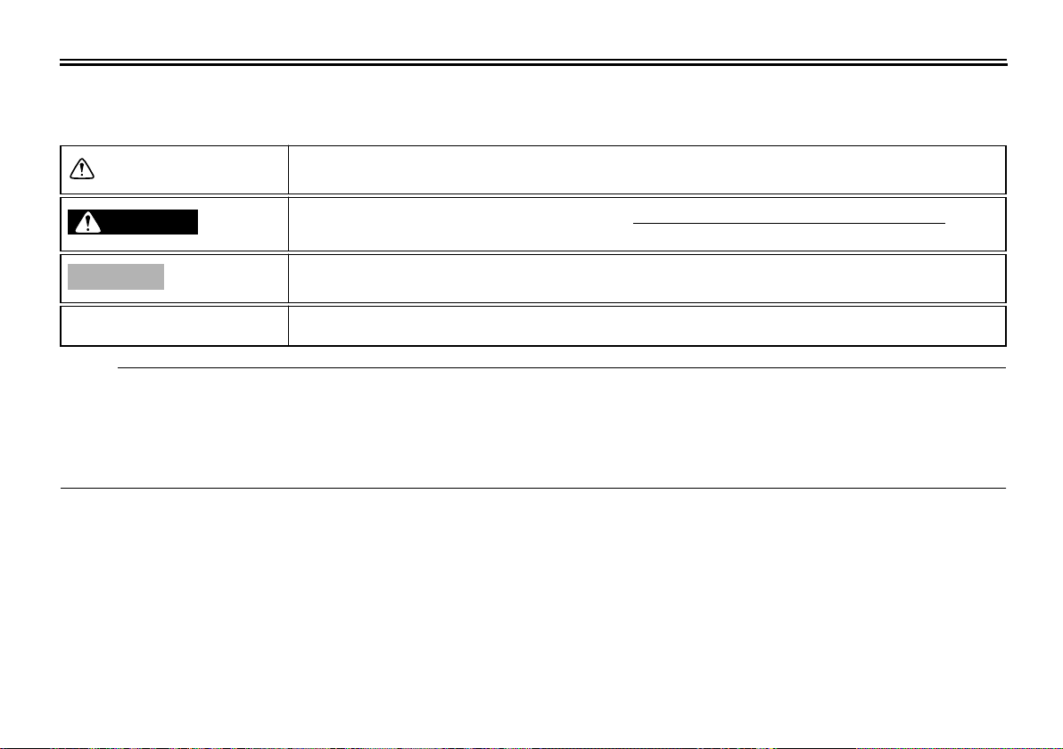
Particularly important information is distinguished in this manual by the following notations:
The Safety Alert Symbol means ATTENTION! BECOME ALERT! YOUR SAFETY IS
INVOLVED!
EAU41090
WARNING
CAUTION:
NOTE:
Failure to follow WARNING instructions could result in severe injury or death to the
motorcycle operator, a bystander or a person inspecting or repairing the motorcycle.
A CAUTION indicates special precautions that must be taken to avoid damage to
the motorcycle.
A NOTE provides key information to make procedures easier or clearer.
NOTE:
●
This manual should be considered a permanent part of this motorcycle and should remain with it even if the motorcycle
is subsequently sold.
●
Yamaha continually seeks advancements in product design and quality. Therefore, while this manual contains the most
current product information available at the time of printing, there may be minor discrepancies between your motorcycle
and this manual. If you have any questions concerning this manual, please consult your Yamaha dealer.
Page 8
IMPORTANT MANUAL INFORMATION
EWA10030
WARNING
PLEASE READ THIS MANUAL CAREFULLY AND COMPLETELY BEFORE OPERATING THIS MOTORCYCLE.
EWA14350
WARNING
THIS MOTORCYCLE IS DESIGNED AND MANUFACTURED FOR OFF-ROAD USE ONLY. IT IS ILLEGAL TO OPERATE THIS MOTORCYCLE ON ANY PUBLIC STREET, ROAD OR HIGHWAY. SUCH USE IS PROHIBITED BY LAW.
THIS MOTORCYCLE COMPLIES WITH ALMOST ALL STATE OFF-HIGHWAY NOISE LEVEL AND SPARK ARRESTER
LAWS AND REGULATIONS. PLEASE CHECK YOUR LOCAL RIDING LAWS AND REGULATIONS BEFORE OPERATING THIS MOTORCYCLE.
*Product and specifications are subject to change without notice.
Page 9
IMPORTANT MANUAL INFORMATION
EAU10200
PW50(X)
OWNER’S MANUAL
©2007 by Yamaha Motor Co., Ltd.
1st edition, April 2007
All rights reserved.
Any reprinting or unauthorized use
without the written permission of
Yamaha Motor Co., Ltd.
is expressly prohibited.
Printed in Japan.
Page 10
TABLE OF CONTENTS
SAFETY INFORMATION
Safe riding ........................................1-1
Location of important labels .............1-4
DESCRIPTION
Left view ...........................................2-1
Right view .........................................2-2
Controls and instruments..................2-3
INSTRUMENT AND CONTROL
FUNCTIONS
Handlebar switch .............................3-1
Speed limiter and power reduction
plate .............................................3-1
Front brake lever .............................3-2
Rear brake lever ..............................3-3
Fuel tank cap ...................................3-3
Fuel ..................................................3-3
Fuel tank breather hose ...................3-5
2-stroke engine oil ...........................3-5
Fuel cock .........................................3-5
Starter (choke) lever “1” .................3-6
Kickstarter ........................................3-6
Seat .................................................3-7
PRE-OPERATION CHECKS
Pre-operation check list ...................4-2
...................................2-1
........................................3-1
...................1-1
...............4-1
OPERATION AND IMPORTANT
RIDING POINTS
Starting and warming up a cold
engine ..........................................5-1
Starting a warm engine ...................5-1
Starting off ....................................... 5-2
Acceleration and deceleration ......... 5-2
Braking ............................................5-2
Engine break-in ...............................5-3
Parking ............................................5-4
PERIODIC MAINTENANCE AND
MINOR REPAIR
Owner’s tool kit ................................ 6-1
Periodic maintenance chart for the
emission control system ..............6-2
General maintenance and lubrication
chart .............................................6-3
Checking the spark plug .................. 6-5
Removing the power reduction
plate .............................................6-6
Transmission oil ..............................6-7
Middle and final gear cases ............6-8
Cleaning the air filter element .........6-8
Cleaning the spark arrester ............. 6-9
Adjusting the carburetor ................6-10
Adjusting the engine idling
speed .........................................6-10
Checking the throttle cable free
play ............................................6-11
Tires ..............................................6-11
..................................5-1
..................................6-1
Panel wheels ................................. 6-13
Accessories and replacement
parts ........................................... 6-13
Adjusting the front and rear brake
lever free play ............................ 6-14
Checking the front and rear brake
shoes ......................................... 6-15
Checking and lubricating the
cables ........................................ 6-15
Checking and lubricating the throttle
grip and cable ............................ 6-16
Adjusting the Autolube pump ........ 6-16
Lubricating the front and rear brake
levers ......................................... 6-16
Checking and lubricating the
centerstand ................................ 6-17
Checking the front fork .................. 6-17
Checking the steering ................... 6-18
Checking the wheel bearings ........ 6-18
Front wheel ................................... 6-19
Rear wheel .................................... 6-20
Troubleshooting ............................ 6-23
Troubleshooting chart ................... 6-24
MOTORCYCLE CARE AND
STORAGE
Matte color caution .......................... 7-1
Care ................................................ 7-1
Storage ........................................... 7-3
SPECIFICATIONS
........................................... 7-1
............................. 8-1
Page 11
TABLE OF CONTENTS
CONSUMER INFORMATION
Identification numbers .....................9-1
..............9-1
Page 12

SAFETY INFORMATION
Safe riding
●
1
●
●
●
●
EAU40931
Always make pre-operation
checks. Careful checks may help
prevent an accident.
This motorcycle is designed for
off-road use only, therefore, it is illegal to operate it on public streets,
roads, or highways, even a dirt or
gravel one. Off-road use on public
lands may be illegal. Please check
local regulations before riding.
This motorcycle is designed to carry the operator only. No passengers.
Many accidents involve inexperienced operators.
●
Make sure that the operator is
qualified and that you only lend
your motorcycle to other qualified operators.
●
Know your skills and limits.
Staying within your limits may
help you to avoid an accident.
Many accidents have been caused
by error of the motorcycle operator. A typical error made by the operator is veering wide on a turn
due to EXCESSIVE SPEED or un-
dercornering (insufficient lean angle for the speed). Never travel
faster than warranted by conditions.
●
Ride cautiously in unfamiliar areas. You may encounter hidden
obstacles that could cause an accident.
●
The posture of the operator is important for proper control. The operator should keep both hands on
the handlebar and both feet on the
operator footrests during operation
to maintain control of the motorcycle.
●
Never ride under the influence of
alcohol or other drugs.
Protective apparel
The majority of fatalities from motorcycle accidents are the result of head injuries. The use of a safety helmet is the
single most critical factor in the prevention or reduction of head injuries.
●
Always wear an approved helmet.
●
Wear a face shield or goggles.
Wind in your unprotected eyes
could contribute to an impairment
1-1
of vision that could delay seeing a
hazard.
●
The use of a jacket, heavy boots,
trousers, gloves, etc., is effective in
preventing or reducing abrasions
or lacerations.
●
Never wear loose-fitting clothes,
otherwise they could catch on the
control levers, footrests, or wheels
and cause injury or an accident.
●
Never touch the engine or exhaust
system during or after operation.
They become very hot and can
cause burns. Always wear protective clothing that covers your legs,
ankles, and feet.
Modifications
Modifications made to this motorcycle
not approved by Yamaha, or the removal of original equipment, may render the motorcycle unsafe for use and
may cause severe personal injury.
Modifications may also make your motorcycle illegal to use.
Loading and accessories
Adding accessories to your motorcycle
Page 13
SAFETY INFORMATION
can adversely affect stability and handling if the weight distribution of the motorcycle is changed. To avoid the
possibility of an accident, use extreme
caution when adding accessories to
your motorcycle. Use extra care when
riding a motorcycle that has added accessories. Here are some general
guidelines to follow if adding accessories to your motorcycle:
Loading
●
The weight of the operator must
not exceed 25 kg (55 lb).
●
Accessory weight should be kept
as low and close to the motorcycle
as possible. Make sure to distribute the weight as evenly as possible on both sides of the motorcycle
to minimize imbalance or instability.
●
Shifting weights can create a sudden imbalance. Make sure that accessories are securely attached to
the motorcycle before riding.
Check accessory mounts frequently.
●
Never attach any large or heavy
items to the handlebar, front fork,
or front fender.
Accessories
Genuine Yamaha accessories have
been specifically designed for use on
this motorcycle. Since Yamaha cannot
test all other accessories that may be
available, you must personally be responsible for the proper selection, installation and use of non-Yamaha
accessories. Use extreme caution
when selecting and installing any accessories.
Keep these guidelines in mind for
mounting accessories in addition to
those provided under “Loading”.
●
Never install accessories or that
would impair the performance of
your motorcycle. Carefully inspect
the accessory before using it to
make sure that it does not in any
way reduce ground clearance or
cornering clearance, limit suspension travel, steering travel or control operation.
●
Accessories fitted to the handlebar or the front fork area can
create instability due to improper
weight distribution or aerodynamic changes. If accessories
are added to the handlebar or
front fork area, they must be as
lightweight as possible and
should be kept to a minimum.
●
Bulky or large accessories may
seriously affect the stability of
the motorcycle due to aerodynamic effects. Wind may attempt to lift the motorcycle, or
the motorcycle may become unstable in cross winds.
●
Certain accessories can displace the operator from his or
her normal riding position. This
improper position limits the freedom of movement of the operator and may limit control ability,
therefore, such accessories are
not recommended.
●
Use caution when adding electrical accessories. If electrical accessories exceed the capacity of the
motorcycle’s electrical system an
electric failure could result, which
could cause a dangerous loss of
1
1-2
Page 14
SAFETY INFORMATION
engine power.
Gasoline and exhaust gas
●
GASOLINE IS HIGHLY FLAMMA-
1
BLE:
●
Always turn the engine off when
refueling.
●
Take care not to spill any gaso-
line on the engine or exhaust
pipe/muffler when refueling.
●
Never refuel while smoking or in
the vicinity of an open flame.
●
Never start the engine or let it run
for any length of time in a closed
area. The exhaust fumes are poisonous and may cause loss of
consciousness and death within a
short time. Always operate your
motorcycle in an area that has adequate ventilation.
●
Always turn the engine off before
leaving the motorcycle unattended. When parking the motorcycle,
note the following:
●
The engine and exhaust pipe/
muffler may be hot, therefore,
park the motorcycle in a place
where pedestrians or children
are not likely to touch these hot
areas.
●
Do not park the motorcycle on a
slope or soft ground, otherwise it
may fall over.
●
Do not park the motorcycle near
a flammable source (e.g., a kerosene heater, or near an open
flame), otherwise it could catch
fire.
●
When transporting the motorcycle
in another vehicle, make sure that
it is kept upright and that the fuel
cock is turned to “S” (stop). If the
motorcycle should lean over, gasoline may leak out of the carburetor or fuel tank.
●
If you should swallow any gasoline, inhale a lot of gasoline vapor,
or allow gasoline to get into your
eyes, see your doctor immediately. If any gasoline spills on your
skin or clothing, immediately wash
the affected area with soap and
water and change your clothes.
1-3
Page 15
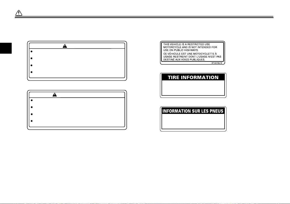
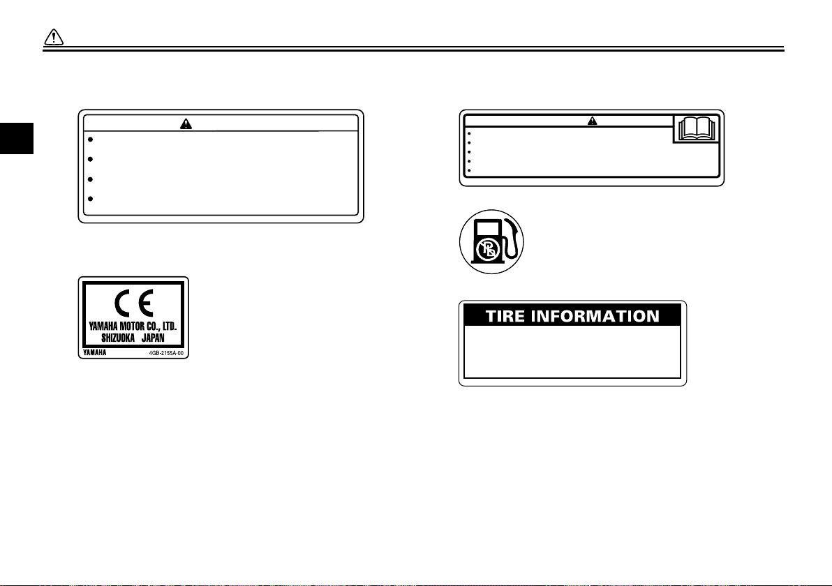
Location of important labels
Please read the following important labels carefully before operating this vehicle.
For Canada
1
5
4
SAFETY INFORMATION
EAU41970
1
32
1-4
Page 16
SAFETY INFORMATION
For Canada
1
1
BEFORE YOU OPERATE THIS VEHICLE,
MANUAL AND ALL
NEVER CARRY
control if you carry a passenger.
OPERATE
NEVER
collide with another vehicle if you operate this vehicle on a public road.
ALWAYS
WEAR AN APPROVED MOTORCYCLE HELMET,
protection, and protective clothing.
eye
WARNING
LABELS.
A PASSENGER.
THIS VEHICLE ON PUBLIC ROADS.
READ
You increaseyour
THE OWNER’S
of losing
risk
You
can
3PT-2118K-A0
2
AVERTISSEMENT
LE
MANUEL
LIRE
ETIQUETTES
NE
JAMAIS
augmente
passager
JAMAIS
NE
Vous
pourriez
TOUJOURS
APPROUVE,
DU
PROPRIETAIRE
AVANT D’UTILISER CE
TRANSPORTER DEPASSAGER.
les risquesde perte decontrôle.
SUR
ROULER
entrerencollision avec un autre véhicule.
PORTER
UN CASQUE DE MOTOCYCLISTE
des
lunettesetdes vêtementsdeprotection.
AINSI
VEHICULE.
DES CHEMINS PUBLICS.
QUE
La
TOUTES
conduite
LES
avec
5PG-2118K-10
3
4
Cold tire normal pressure should be set as
follows.
FRONT :
100 kPa,{1.00 kgf/cm2}, 15 psi
100 kPa,{1.00 kgf/cm2}, 15 psi
:REAR
3RV-21668-A0
5
La pression des pneus à froid doit normallement
être réglée comme suit.
AVANT :
ARRIERE
100 kPa,{1.00 kgf/cm2}, 15 psi
100 kPa,{1.00 kgf/cm2}, 15 psi
:
3RV-21668-B0
1-5
Page 17
Except for Canada
SAFETY INFORMATION
1
2
5
43
1
1-6
Page 18
SAFETY INFORMATION
Except for Canada
1
WARNING
1
BEFORE YOU OPERATE THIS VEHICLE,
MANUAL AND ALL
NEVER CARRY
control if you carry a passenger.
OPERATE
NEVER
collide with another vehicle if you operate this vehicle on a public road.
ALWAYS
WEAR AN APPROVED MOTORCYCLE HELMET,
protection, and protective clothing.
eye
LABELS.
A PASSENGER.
THIS VEHICLE ON PUBLIC ROADS.
You increaseyour
READ
THE OWNER’S
of losing
risk
You
can
3PT-2118K-A0
3
Before you operate this vehicle, read the owner’s manual.
Prima di usare il veicolo, leggete il manuale di istruzioni.
Lire le manuel du propri
Lesen Sie die Bedienungsanleitung bevor Sie dieses Fahrzeug fahren.
Antes de conducir este vehículo, lea el Manual del Propietario.
étaire avant d
’utiliser ce v
éhicule.
5PA-21568-00
4
2
5
Cold tire normal pressure should be set as
follows.
FRONT :
100 kPa,{1.00 kgf/cm2}, 15 psi
:REAR
100 kPa,{1.00 kgf/cm2}, 15 psi
3RV-21668-A0
1-7
Page 19

SAFETY INFORMATION
1-812-1
Page 20
DESCRIPTION
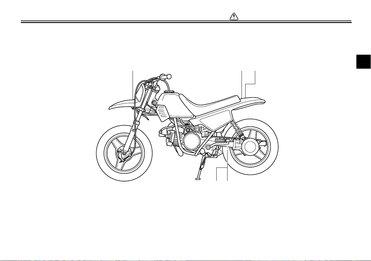
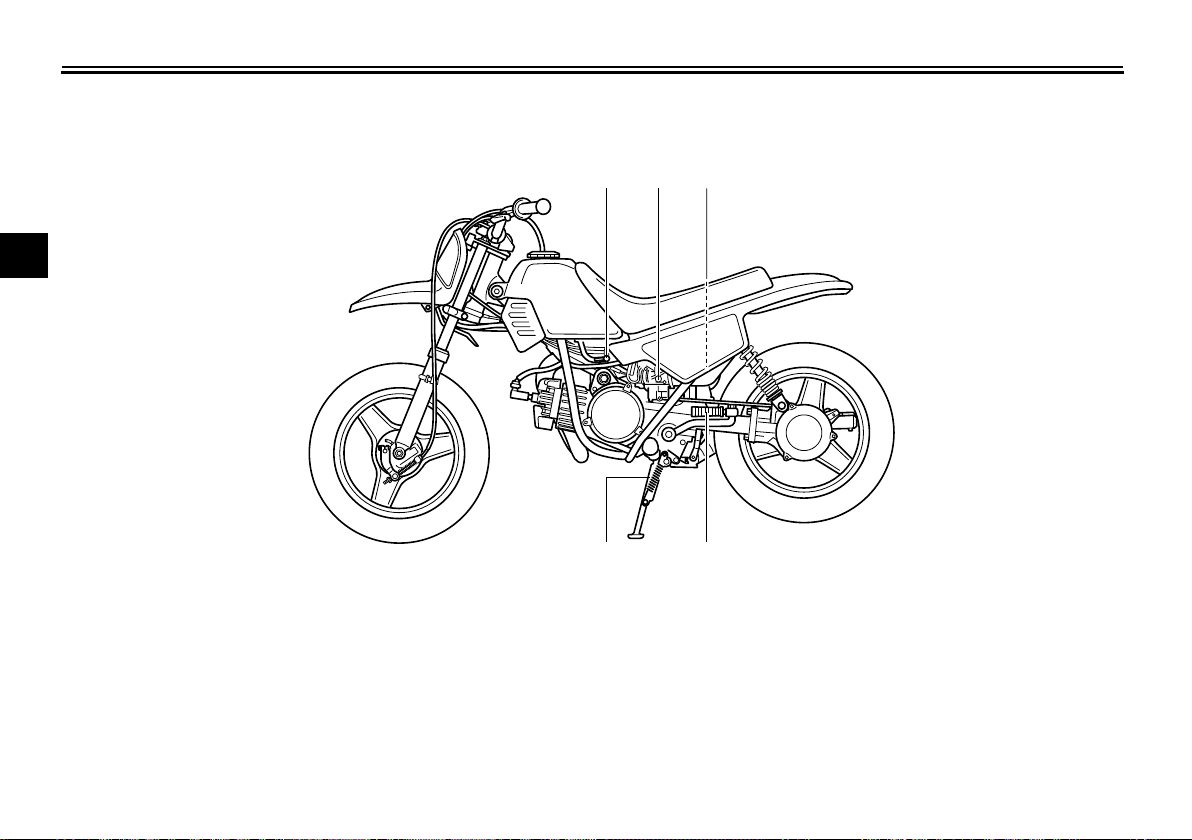
Left view
EAU10410
1
2
3
4
5
6
7
8
1. Fuel cock (page 3-5)
2. Throttle stop screw (page 6-10)
9
3. Air filter element (page 6-8)
4. Kickstarter (page 3-6)
5. Centerstand (page 6-17)
123
45
Page 21
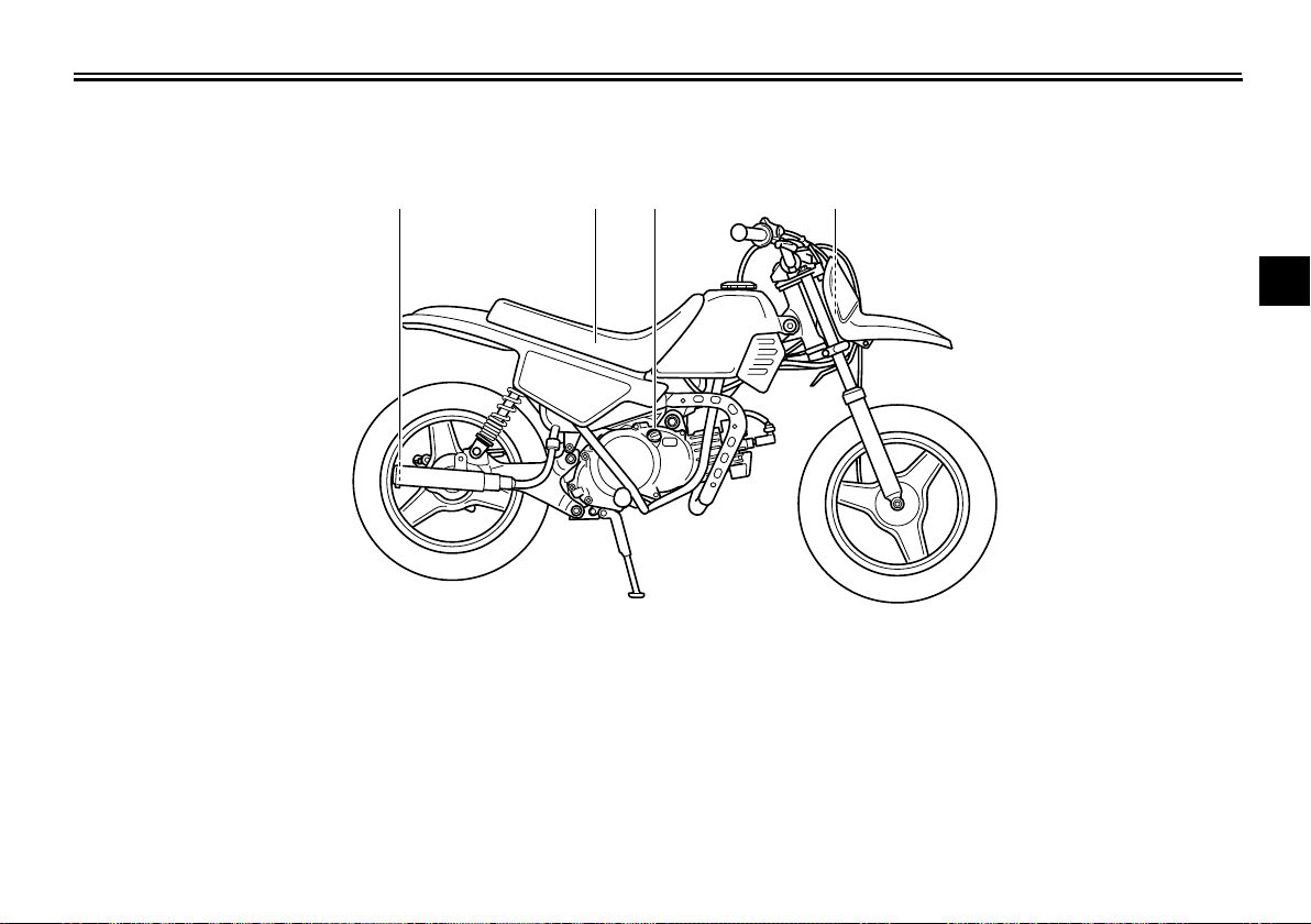
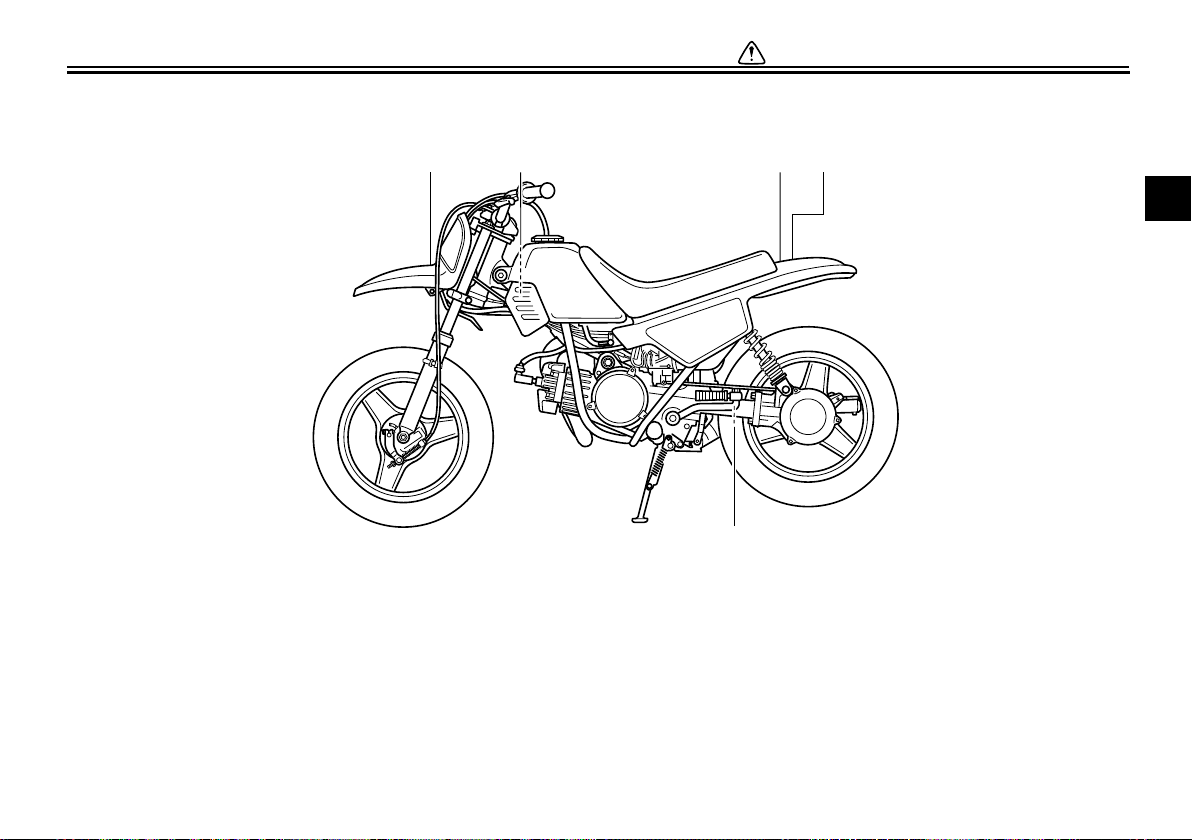
Right view
DESCRIPTION
EAU10420
2
1
3
4
2
3
4
5
6
7
1. Spark arrester (page 6-9)
2. Seat (page 3-7)
3. Transmission oil filler cap (page 6-7)
4. 2-stroke engine oil tank (page 3-5)
8
9
2-2
Page 22

DESCRIPTION
Controls and instruments
EAU10430
1
2
3
4
5
6
7
8
1. Rear brake lever (page 3-3)
2. Starter (choke) lever (page 3-6)
9
3. 2-stroke engine oil tank cap (page 3-5)
4. Right handlebar switch (page 3-1)
5. Front brake lever (page 3-2)
6. Throttle grip (page 6-11)
7. Fuel tank cap (page 3-3)
12
345
7
6
2-3
Page 23

INSTRUMENT AND CONTROL FUNCTIONS
EAU40660
Handlebar switch
1
1. Engine stop switch “OFF/RUN/START”
EAU40673
Engine stop switch “OFF/RUN/
START”
Set this switch to “START” before starting the engine. Set this switch to “RUN”
after warming up the engine or before
starting off. Set this switch to “OFF” to
stop the engine.
NOTE:
The engine cannot be started with
●
this switch set to the “RUN” position.
The engine speed is limited while
●
this switch is set to the “START”
position, therefore the motorcycle
cannot be ridden in that switch position.
3-1
EAU41041
Speed limiter and power
reduction plate
Your motorcycle was delivered with an
adjustable speed limiter and a power
reduction plate. The speed limiter
keeps the throttle from fully opening,
even when the throttle grip is turned to
the maximum. The power reduction
plate is installed in the exhaust manifold to limit the amount of power available while they learn.
Speed limiter
1. Loosen the locknut.
2. To increase the maximum engine
power available and the maximum
speed of the motorcycle, turn the
adjusting screw in direction (a). To
decrease the maximum engine
power available and the maximum
speed of the motorcycle, turn the
adjusting screw in direction (b).
2
3
4
5
6
7
8
9
Page 24

INSTRUMENT AND CONTROL FUNCTIONS
1
1
1
(b)
2
(a)
3
1. Locknut
2. Adjusting screw
4
3. Tighten the locknut.
5
6
7
8
9
1. No more than 7 mm (0.28 in)
NOTE:
The adjusting range of the speed limiter
screw is from the fully turned-in position
to 7 mm (0.28 in) turned out. When the
1
screw is turned out to 7 mm (0.28 in),
2
the throttle grip can only be opened ap-
Front brake lever
EAU12900
proximately halfway. If more power is
required, please consult a Yamaha
dealer.
EWA14630
WARNING
Improper adjustment of the speed
limiter could cause improper throttle
operation. You could lose control,
have an accident or be injured. Do
not turn the adjusting screw out
1. Front brake lever
more than 7 mm (0.28 in) before consulting a Yamaha dealer. Always
make sure the throttle cable free
play is adjusted to 1.5–3.5 mm
(0.06–0.14 in). (See page 6-11.)
The front brake lever is located on the
right handlebar grip. To apply the front
brake, pull this lever toward the handlebar grip.
Power reduction plate
Once the rider can operate with skill at
the top speed permitted by adjusting
the speed limiter alone, the power reduction plate can be removed. (See
page 6-6.)
3-2
Page 25

INSTRUMENT AND CONTROL FUNCTIONS
2
1
EAU12950
Rear brake lever
1
1. Rear brake lever
The rear brake lever is located on the
left handlebar grip. To apply the rear
brake, pull this lever toward the handlebar grip.
EAU13181
Fuel tank cap
1
1. Fuel tank cap
To remove the fuel tank cap, turn it
counterclockwise, and then pull it off.
To install the fuel tank cap, insert it into
the tank opening, and then turn it clockwise.
EWA11090
WARNING
Make sure that the fuel tank cap is
properly closed before riding.
EAU13220
Fuel
1. Fuel tank filler tube
2. Fuel level
Make sure that there is sufficient fuel in
the tank. When refueling, be sure to insert the pump nozzle into the fuel tank
filler hole and to fill the tank to the bottom of the filler tube as shown.
WARNING
Do not overfill the fuel tank, oth-
●
erwise it may overflow when the
fuel warms up and expands.
Avoid spilling fuel on the hot en-
●
gine.
EWA10880
2
3
4
5
6
7
8
9
3-3
Page 26

INSTRUMENT AND CONTROL FUNCTIONS
CAUTION:
Immediately wipe off spilled fuel
with a clean, dry, soft cloth, since
1
fuel may deteriorate painted surfaces or plastic parts.
2
3
For Canada
4
5
Recommended fuel:
REGULAR UNLEADED GASOLINE
ONLY
Fuel tank capacity:
2.0 L (0.53 US gal) (0.44 Imp.gal)
6
CAUTION:
7
Use only unleaded gasoline. The use
of leaded gasoline will cause severe
damage to internal engine parts,
8
such as the piston rings as well as to
the exhaust system.
9
Your Yamaha engine has been designed to use regular unleaded gasoline with a pump octane number
[(R+M)/2] of 86 or higher, or a research
octane number of 91 or higher. If
ECA10070
EAU41980
ECA15590
knocking (or pinging) occurs, use a
gasoline of a different brand or premium unleaded fuel. Use of unleaded fuel
will extend spark plug life and reduce
maintenance cost.
Gasohol
There are two types of gasohol: gasohol containing ethanol and that containing methanol. Gasohol containing
ethanol can be used if ethanol content
does not exceed 10%. Gasohol containing methanol is not recommended
by Yamaha because it can cause damage to the fuel system or vehicle performance problems.
Except for Canada
Recommended fuel:
For Europe: REGULAR UNLEADED
GASOLINE ONLY
Except for Canada and Europe: UNLEADED GASOLINE ONLY
Fuel tank capacity:
2.0 L (0.53 US gal) (0.44 Imp.gal)
ECA15590
CAUTION:
Use only unleaded gasoline. The use
of leaded gasoline will cause severe
damage to internal engine parts,
such as the piston rings as well as to
the exhaust system.
Your Yamaha engine has been designed to use regular unleaded gasoline with a research octane number of
91 or higher. If knocking (or pinging) occurs, use a gasoline of a different brand
or premium unleaded fuel. Use of unleaded fuel will extend spark plug life
and reduce maintenance costs.
3-4
Page 27

INSTRUMENT AND CONTROL FUNCTIONS
1
Fuel tank breather hose
1
1. Fuel tank breather hose
Before operating the motorcycle:
●
Check the fuel tank breather hose
connection.
●
Check the fuel tank breather hose
for cracks or damage, and replace
it if damaged.
●
Make sure that the fuel tank
breather hose is not blocked, and
clean it if necessary.
EAU13412
EAU13452
2-stroke engine oil
Make sure that there is sufficient
2-stroke engine oil in the oil tank. Add
the recommended 2-stroke engine oil
as necessary.
1
2
1. 2-stroke engine oil tank cap
2. Minimum level mark
Recommended oil:
See page 8-1.
Oil quantity:
0.30 L (0.32 US qt) (0.26 Imp.qt)
NOTE:
Make sure that the 2-stroke engine oil
tank cap is properly installed.
EAU40701
Fuel cock
The fuel cock supplies fuel from the
tank to the carburetor while filtering it also.
The fuel cock has two positions:
S (stop)
1. Arrow mark pointing to “S” (stop)
With the lever in this position, fuel will
not flow. Always return the lever to this
position when the engine is not running.
2
3
4
5
6
7
8
9
3-5
Page 28

INSTRUMENT AND CONTROL FUNCTIONS
1
O (on)
1
2
3
1. Arrow mark pointing to “O” (on)
4
With the lever in this position, fuel flows
to the carburetor. Normal riding is done
5
with the lever in this position.
6
7
8
9
EAU13590
Starter (choke) lever “”
1
(a)
Kickstarter
EAU13680
(b)
1
1. Starter (choke) lever “”
Starting a cold engine requires a richer
air-fuel mixture, which is supplied by
the starter (choke).
Move the lever in direction (a) to turn on
the starter (choke).
Move the lever in direction (b) to turn off
the starter (choke).
1. Kickstarter
To start the engine, fold out the kickstarter lever, move it down lightly with
your foot until the gears engage, and
then push it down smoothly but forcefully.
3-6
Page 29

Seat
To remove the seat
1. Remove the mudguard by removing the bolts and washers.
1
1. Bolt
2. Mudguard
2. Pull the seat off.
EAU40920
2
INSTRUMENT AND CONTROL FUNCTIONS
1
2
1. Seat holder
2. Projection
2. Place the seat in the original position.
3. Install the mudguard by installing
the washers and bolts.
NOTE:
Make sure that the seat is properly secured before riding.
2
3
4
5
6
7
To install the seat
1. Insert the projection on the front of
the seat into the seat holder as
shown.
8
9
3-7
Page 30

PRE-OPERATION CHECKS
The condition of a vehicle is the owner’s responsibility. Vital components can start to deteriorate quickly and unexpectedly,
even if the vehicle remains unused (for example, as a result of exposure to the elements). Any damage, fluid leakage or loss
of tire air pressure could have serious consequences. Therefore, it is very important, in addition to a thorough visual inspec-
1
tion, to check the following points before each ride.
NOTE:
2
Pre-operation checks should be made each time the vehicle is used. Such an inspection can be accomplished in a very short
time; and the added safety it assures is more than worth the time involved.
3
4
5
6
7
8
WARNING
If any item in the Pre-operation check list is not working properly, have it inspected and repaired before operating
the vehicle.
EAU15593
EWA11150
9
4-1
Page 31

Pre-operation check list
ITEM CHECKS PAGE
Fuel
2-stroke engine oil
Middle and final gear cases
Front brake
Rear brake
Throttle grip
Control cables
Wheels and tires
Brake levers
Centerstand
PRE-OPERATION CHECKS
●
Check fuel level in fuel tank.
●
Refuel if necessary.
●
Check fuel line for leakage.
●
Check oil level in oil tank.
●
If necessary, add recommended oil to specified level.
●
Check vehicle for oil leakage.
●
Check vehicle for grease leakage. 6-8
●
Check operation.
Lubricate cable if necessary.
●
Check lever free play.
●
Adjust if necessary.
●
Check operation.
●
●
Lubricate cable if necessary.
Check lever free play.
●
Adjust if necessary.
●
Make sure that operation is smooth.
●
Check cable free play.
●
If necessary, have Yamaha dealer adjust cable free play and lubricate cable
●
and grip housing.
Make sure that operation is smooth.
●
Lubricate if necessary.
●
Check for damage.
●
Check tire condition and tread depth.
●
Check air pressure.
●
Correct if necessary.
●
Make sure that operation is smooth.
●
Lubricate lever pivoting points if necessary.
●
Make sure that operation is smooth.
●
Lubricate pivot if necessary.
●
3-3
3-5
6-14, 6-15
6-14, 6-15
6-11, 6-16
6-15
6-11, 6-13
6-16
6-17
EAU15605
2
3
4
5
6
7
8
9
4-2
Page 32

PRE-OPERATION CHECKS
ITEM CHECKS PAGE
●
Chassis fasteners
Engine stop switch
1
2
3
4
5
6
7
8
Make sure that all nuts, bolts and screws are properly tightened.
●
Tighten if necessary.
●
Check operation. 3-1
—
9
4-3
Page 33

OPERATION AND IMPORTANT RIDING POINTS
WARNING
●
This model is designed for
off-road use only. Become thoroughly familiar with all operating controls and their functions
before riding. Consult a Yamaha
dealer regarding any control or
function that you do not thoroughly understand.
Never start the engine or oper-
●
ate it in a closed area for any
length of time. Exhaust fumes
are poisonous, and inhaling
them can cause loss of consciousness and death within a
short time. Always make sure
that there is adequate ventilation.
EAU40771
EWA14531
EAU40883
Starting and warming up a
cold engine
1. Turn the fuel cock lever to “O” (on).
2. Set the engine stop switch to
“START”.
3. Turn the starter (choke) on and
completely close the throttle. (See
page 3-6.)
4. While applying the front or rear
brake, start the engine by pushing
the kickstarter lever down.
5. After starting the engine, move the
starter (choke) back halfway.
ECA11130
CAUTION:
For maximum engine life, always
warm the engine up before starting
off. Never accelerate hard when the
engine is cold!
6. When the engine is warm, turn the
starter (choke) off and set the engine stop switch to “RUN”.
NOTE:
The engine is warm when it responds
normally to the throttle with the starter
(choke) turned off.
EAU16660
Starting a warm engine
Follow the same procedure as for starting a cold engine with the exception
that the starter (choke) is not required
when the engine is warm. Instead, start
the engine with the throttle slightly
open.
NOTE:
If the engine does not start after several kicks, try again with the throttle 1/4
to 1/2 open.
2
3
4
5
6
7
8
9
5-1
Page 34

OPERATION AND IMPORTANT RIDING POINTS
Starting off
NOTE:
Before starting off, allow the engine to
1
warm up.
1. While applying the rear brake le-
2
3
4
5
6
7
8
9
ver, push the motorcycle off the
centerstand.
2. Completely close the throttle.
3. Set the engine stop switch to
“RUN”.
4. Check for oncoming off-road vehicles, and then slowly turn the throttle grip in order to take off.
EAU41000
EAU16780
Acceleration and deceleration
(b)
(a)
The speed can be adjusted by opening
and closing the throttle. To increase the
speed, turn the throttle grip in direction
(a). To reduce the speed, turn the throttle grip in direction (b).
EAU41011
Braking
1. Close the throttle completely.
2. Apply both front and rear brakes
simultaneously while gradually increasing the pressure.
Front
5-2
Page 35

OPERATION AND IMPORTANT RIDING POINTS
Rear
WARNING
Avoid braking hard or suddenly
●
(especially when leaning over to
one side), otherwise the motorcycle may skid or overturn.
Keep in mind that braking on
●
wet surfaces is much more difficult.
●
Ride slowly down a hill, as braking downhill can be very difficult.
EWA14571
EAU42030
Engine break-in
There is never a more important period
in the life of your engine than the first 5
hours of riding. It is also important to accustom the rider to the motorcycle during this time. Please read the following
information carefully.
Since the engine is brand new, do not
put an excessive load on it for the first 5
hours of operation. The various parts in
the engine wear and polish themselves
to the correct operating clearances.
During this period, prolonged full-throttle operation or any condition that might
result in engine overheating must be
avoided. However, momentary
full-throttle operation under load (i.e.,
two to three seconds maximum) does
not harm the engine. Each full-throttle
acceleration should be followed with a
substantial rest period for the engine.
To allow the engine to cool down from
the temporary buildup of heat, cruise at
a lower engine speed.
After the first 5 hours of operation, thoroughly check the motorcycle for loose
parts, oil leakage and any other problems. Be sure to inspect and make ad-
5-3
justments thoroughly, especially
cables. In addition, check all fittings and
fasteners for looseness, and tighten if
necessary.
ECA10270
CAUTION:
If any engine trouble should occur
during the engine break-in period,
immediately have a Yamaha dealer
check the vehicle.
2
3
4
5
6
7
8
9
Page 36

OPERATION AND IMPORTANT RIDING POINTS
EAU40721
Parking
When parking, stop the engine, and
then turn the fuel cock lever to “S”
(stop).
1
WARNING
2
●
Since the engine and exhaust
system can become very hot,
3
park in a place where pedestrians or children are not likely to
4
5
touch them.
Do not park on a slope or on soft
●
ground, otherwise the vehicle
may overturn.
6
7
8
EWA10310
9
5-4
Page 37

PERIODIC MAINTENANCE AND MINOR REPAIR
EAU41950
Safety is an obligation of the owner. Periodic inspection, adjustment and lubrication will keep your vehicle in the
safest and most efficient condition possible. The most important points of motorcycle inspection, adjustment, and
lubrication are explained on the following pages.
Maintenance, replacement, or repair
of the emission control devices and
systems may be performed by any
repair establishment or individual
that is certified (if applicable).
EWA10320
WARNING
If you are not familiar with maintenance work, have a Yamaha dealer
do it for you.
EAU17320
Owner’s tool kit
The service information included in this
manual and the tools provided in the
owner’s tool kit are intended to assist
you in the performance of preventive
maintenance and minor repairs. However, additional tools such as a torque
wrench may be necessary to perform
certain maintenance work correctly.
NOTE:
If you do not have the tools or experience required for a particular job, have
a Yamaha dealer perform it for you.
EWA10350
WARNING
Modifications not approved by
Yamaha may cause loss of performance and render the vehicle unsafe for use. Consult a Yamaha
dealer before attempting any changes.
2
3
4
5
6
7
8
9
6-1
Page 38

PERIODIC MAINTENANCE AND MINOR REPAIR
Periodic maintenance chart for the emission control system
NOTE:
From 18 months, repeat the maintenance intervals starting from 6 months.
●
1
2
3
4
5
6
7
8
9
Items marked with an asterisk should be performed by a Yamaha dealer as they require special tools, data and technical
●
skills.
NO. ITEM CHECK OR MAINTENANCE JOB
1*Fuel line
2 Spark plug
3 Air filter element
4*Carburetor
Cylinder head and
5*
exhaust system
6*Spark arrester
Check fuel hoses for cracks or damage.
Replace if necessary.
Check condition.
Adjust gap and clean.
Replace if necessary.
Clean with solvent.
Replace if necessary.
Check engine idling speed and starter operation.
Adjust if necessary.
Clean.
Check for leakage.
Tighten if necessary.
Decarbonize if necessary.
Clean.
INITIAL
1
month3 months6 months6 months
THEREAFTER
EAU41741
EVERY
12
months
6-2
Page 39

PERIODIC MAINTENANCE AND MINOR REPAIR
General maintenance and lubrication chart
EAU41752
NO. ITEM CHECK OR MAINTENANCE JOB
Check operation.
1*Front brake
2*Rear brake
3*Wheels
4*Tires
5*Wheel bearings
6*Steering bearings
Middle and final gear
7*
cases
8*Chassis fasteners
9*Autolube pump
Adjust brake lever free play.
Replace brake shoes. Whenever worn to the limit
Check operation.
Adjust brake lever free play.
Replace brake shoes. Whenever worn to the limit
Check runout and for damage.
Replace if necessary.
Check tread depth and for damage.
Replace if necessary.
Check air pressure.
Correct if necessary.
Check bearings for smooth operation.
Replace if necessary.
Check bearing assemblies for looseness.
Moderately repack with lithium-soap-based
grease every 2 years.
Check for grease leakage.
Check gears for damage and wear.
Lubricate gears with lithium-soap-based grease.
Check all chassis fitting and fasteners.
Correct if necessary.
Check operation.
Correct if necessary.
Bleed.
INITIAL
1
month3months6months6months
Every 2 years
THEREAFTER
EVERY
12
months
2
3
4
5
6
7
8
9
6-3
Page 40

PERIODIC MAINTENANCE AND MINOR REPAIR
1
2
3
4
5
6
7
NO. ITEM CHECK OR MAINTENANCE JOB
Check for oil leakage.
10
* Transmission oil
Front and rear brake
11
*
lever pivot
12
* Centerstand pivot
Shock absorber
13
*
assemblies
14
* Control cable
Throttle grip housing
15
*
and cable
Correct if necessary.
Change.
Apply lithium-soap-based grease (all-purpose
grease) lightly.
Check operation.
Apply lithium-soap-based grease (all-purpose
grease) lightly.
Check operation and for oil leakage.
Replace if necessary.
Apply Yamaha chain and cable lube or engine oil
10W-30 lightly.
Check operation and free play.
Apply Yamaha chain and cable lube or engine oil
10W-30 lightly.
NOTE:
1
month3months6months6months
The air filter needs more frequent service if you are riding in unusually wet or dusty areas.
8
9
INITIAL
THEREAFTER
EVERY
12
months
6-4
Page 41

PERIODIC MAINTENANCE AND MINOR REPAIR
1
EAU19603
Checking the spark plug
The spark plug is an important engine
component, which is easy to check.
Since heat and deposits will cause any
spark plug to slowly erode, the spark
plug should be removed and checked
in accordance with the periodic maintenance and lubrication chart. In addition,
the condition of the spark plug can reveal the condition of the engine.
To remove the spark plug
1. Remove the spark plug cap.
1
1. Spark plug cap
2. Remove the spark plug as shown,
with the spark plug wrench included in the owner’s tool kit.
1
1. Spark plug wrench
To check the spark plug
1. Check that the porcelain insulator
around the center electrode of the
spark plug is a medium-to-light tan
(the ideal color when the vehicle is
ridden normally).
NOTE:
If the spark plug shows a distinctly different color, the engine could be operating improperly. Do not attempt to
diagnose such problems yourself. Instead, have a Yamaha dealer check
the vehicle.
2. Check the spark plug for electrode
erosion and excessive carbon or
other deposits, and replace it if
necessary.
Specified spark plug:
NGK/BP4HS (AUS)(NZL)
NGK/BPR4HS
(AUT)(BEL)(CAN)(CHE)(DEU)
(DNK)(ESP)(FIN)(FRA)(GBR)(GRC)
(IRL)(NLD)(NOR)(PRT)(SWE)(ZAF)
DENSO/W14FPL (AUS)(NZL)
To install the spark plug
1. Measure the spark plug gap with a
wire thickness gauge and, if necessary, adjust the gap to specification.
1. Spark plug gap
Spark plug gap:
0.6–0.7 mm (0.024–0.028 in)
2. Clean the surface of the spark plug
2
3
4
5
6
7
8
9
6-5
Page 42

PERIODIC MAINTENANCE AND MINOR REPAIR
gasket and its mating surface, and
then wipe off any grime from the
spark plug threads.
3. Install the spark plug with the
1
spark plug wrench, and then tighten it to the specified torque.
2
3
4
Tightening torque:
Spark plug:
20 Nm (2.0 m·kgf, 14.5 ft·lbf)
NOTE:
If a torque wrench is not available when
installing a spark plug, a good estimate
5
of the correct torque is 1/4–1/2 turn
past finger tight. However, the spark
plug should be tightened to the speci-
6
fied torque as soon as possible.
4. Install the spark plug cap.
7
8
9
EAU41100
Removing the power
reduction plate
To obtain full engine performance capability, removing the power reduction
plate is required.
EWA14580
WARNING
Always let the exhaust system cool
prior to touching exhaust components.
1. Remove the exhaust manifold by
removing the bolts.
1
1. Exhaust manifold bolt
2. Remove the gasket.
3. Remove the power reduction
plate.
1
2
3
1. Exhaust manifold
2. Gasket
3. Power reduction plate
NOTE:
Store the power reduction plate with the
owner’s manual so that it is readily
available whenever you want to reduce
the engine power.
4. Install the exhaust manifold by installing the bolts.
Tightening torque:
Exhaust manifold bolt:
8.5 Nm (0.9 m·kgf, 6.1 ft·lbf)
6-6
Page 43

PERIODIC MAINTENANCE AND MINOR REPAIR
EAU40891
Transmission oil
The transmission oil must be checked
for oil leakage before each ride. If any
leakage is found, have a Yamaha dealer check and repair the motorcycle. In
addition, the transmission oil must be
changed at the intervals specified in the
periodic maintenance and lubrication
chart.
1. Place the motorcycle on the centerstand.
2. Place an oil pan under the transmission to collect the used oil.
3. Remove the oil filler cap and drain
bolt to drain the oil from the transmission.
1
1. Transmission oil filler cap
1
1. Transmission oil drain bolt
4. Install the transmission oil drain
bolt, and then tighten it to the specified torque.
Tightening torque:
Transmission oil drain bolt:
14 Nm (1.4 m·kgf, 10.1 ft·lbf)
5. Add the specified amount of the
recommended transmission oil,
and then install and tighten the oil
filler cap.
Recommended transmission oil:
See page 8-1.
Oil change quantity:
0.30 L (0.32 US qt) (0.26 Imp.qt)
ECA10452
CAUTION:
In order to prevent clutch slip-
●
page (since the transmission oil
also lubricates the clutch), do
not mix any chemical additives.
Do not use oils with a diesel
specification of “CD” or oils of a
higher quality than specified. In
addition, do not use oils labeled
“ENERGY CONSERVING II” or
higher.
Make sure that no foreign mate-
●
rial enters the transmission.
6. Start the engine, and then let it idle
for several minutes while checking
the transmission for oil leakage. If
oil is leaking, immediately turn the
engine off and check for the cause.
2
3
4
5
6
7
8
9
6-7
Page 44

PERIODIC MAINTENANCE AND MINOR REPAIR
1
Middle and final gear cases
The middle and final gear cases must
be checked for grease leakage before
each ride. If any leakage is found, have
1
a Yamaha dealer check and repair the
motorcycle. In addition, have a
2
Yamaha dealer check and lubricate the
middle and final gears at the intervals
3
specified in the periodic maintenance
and lubrication chart.
4
5
6
7
8
9
EAU41711
EAU40901
Cleaning the air filter element
The air filter element should be cleaned
at the intervals specified in the periodic
maintenance and lubrication chart.
Clean the air filter element more frequently if you are riding in unusually
wet or dusty areas.
1. Remove the seat. (See page 3-7.)
2. Remove the air filter case cover by
removing the screw.
1
2
1. Air filter case cover
2. Screw
3. Pull the sponge material out, clean
it with solvent, and then squeeze
the remaining solvent out.
1. Sponge material
4. Apply oil of the recommended type
to the entire surface of the sponge
material, and then squeeze the excess oil out.
NOTE:
The sponge material should be wet but
6-8
Page 45

PERIODIC MAINTENANCE AND MINOR REPAIR
1
2
3
not dripping.
Recommended oil:
Yamaha foam air filter oil or other
quality foam air filter oil
5. Insert the sponge material into the
air filter case.
CAUTION:
●
Make sure that the sponge material is properly seated in the
air filter case.
●
The engine should never be operated without the sponge material installed, otherwise the
piston(s) and/or cylinder(s) may
become excessively worn.
6. Install the air filter case cover by installing the screw.
7. Install the seat.
ECA15620
EAU41220
Cleaning the spark arrester
The spark arrester should be cleaned
at the intervals specified in the periodic
maintenance and lubrication chart.
WARNING
●
Always let the exhaust system
cool prior to touching exhaust
components.
Do not start the engine when
●
cleaning the exhaust system.
NOTE:
Make sure to select a well-ventilated
area free of combustible materials to
clean the spark arrester.
1. Remove the tailpipe by removing
the screw, and then pulling it out of
the muffler.
EWA10980
1. Tailpipe
2. Screw
3. Muffler
2. Tap the tailpipe lightly, and then
use a wire brush to remove any
carbon deposits from the spark arrester portion of the tailpipe and inside of the tailpipe housing.
2
3
4
5
6
7
8
9
6-9
Page 46

PERIODIC MAINTENANCE AND MINOR REPAIR
1
2
3
1. Spark arrester
4
3. Insert the tailpipe into the muffler,
1
and then install and tighten the
5
screw.
NOTE:
Make sure to align the screw hole when
6
inserting the tailpipe.
7
8
9
EAU39930
Adjusting the carburetor
The carburetor is an important part of
the engine and requires very sophisticated adjustment. Therefore, most carburetor adjustments should be left to a
Yamaha dealer, who has the necessary professional knowledge and experience. The adjustment described in the
following section, however, may be serviced by the owner as part of routine
maintenance.
ECA10550
CAUTION:
The carburetor has been set and extensively tested at the Yamaha factory. Changing these settings
without sufficient technical knowledge may result in poor performance of or damage to the engine.
EAU21360
Adjusting the engine idling
speed
The engine idling speed must be
checked and, if necessary, adjusted as
follows at the intervals specified in the
periodic maintenance and lubrication
chart.
NOTE:
A diagnostic tachometer is needed to
make this adjustment.
1. Attach the tachometer to the spark
plug lead.
2. Start the engine and warm it up
for several minutes at 1000–2000
r/min while occasionally revving it
to 4000–5000 r/min.
NOTE:
The engine is warm when it quickly responds to the throttle.
3. Check the engine idling speed
and, if necessary, adjust it to specification by turning the throttle stop
screw. To increase the engine
idling speed, turn the screw in direction (a). To decrease the engine idling speed, turn the screw in
6-10
Page 47

PERIODIC MAINTENANCE AND MINOR REPAIR
direction (b).
(b)
(a)
1
1. Throttle stop screw
Engine idling speed:
1650–1750 r/min
NOTE:
If the specified idling speed cannot be
obtained as described above, have a
Yamaha dealer make the adjustment.
EAU21382
Checking the throttle cable
free play
1
1. Throttle cable free play
The throttle cable free play should measure 1.5–3.5 mm (0.06–0.14 in) at the
throttle grip. Periodically check the
throttle cable free play and, if necessary, have a Yamaha dealer adjust it.
EAU40910
Tires
To maximize the performance, durability, and safe operation of your motorcycle, note the following points regarding
the specified tires.
Tire air pressure
The tire air pressure should be checked
and, if necessary, adjusted before each
ride.
WARNING
The tire air pressure must be
●
checked and adjusted on cold
tires (i.e., when the temperature
of the tires equals the ambient
temperature).
The tire air pressure must be ad-
●
justed in accordance with the
weight of the rider, the riding
speed, and the riding conditions.
Standard tire air pressure:
Front:
100 kPa (15 psi) (1.00 kgf/cm2)
Rear:
100 kPa (15 psi) (1.00 kgf/cm2)
EWA14380
2
3
4
5
6
7
8
9
6-11
Page 48

PERIODIC MAINTENANCE AND MINOR REPAIR
Tire inspection
1
2
1
3
1. Tire sidewall
4
2. Tire tread depth
The tires must be checked before each
5
ride. If the center tread depth reaches
the specified limit, if the tire has a nail or
6
glass fragments in it, or if the sidewall is
cracked, have a Yamaha dealer re-
7
place the tire immediately.
8
Minimum tire tread depth (front and
rear):
4.0 mm (0.16 in)
9
Tire information
This motorcycle is equipped with panel
wheels and tube tires.
EWA10460
WARNING
●
2
The front and rear tires should
be of the same make and design, otherwise the handling
characteristics of the vehicle
cannot be guaranteed.
●
After extensive tests, only the
tires listed below have been approved for this model by
Yamaha Motor Co., Ltd.
sively worn tires decreases
riding stability and can lead to
loss of control.
●
The replacement of all
wheel-and brake-related parts,
including the tires, should be
left to a Yamaha dealer, who has
the necessary professional
knowledge and experience.
●
It is not recommended to patch
a punctured tube. If unavoidable, however, patch the tube
Front tire:
Size:
2.50-10 4PR
Manufacturer/model:
BRIDGESTONE/KNOBBY
IRC/KNOBBY
Rear tire:
Size:
2.50-10 4PR
Manufacturer/model:
BRIDGESTONE/KNOBBY
IRC/KNOBBY
EWA14390
very carefully and replace it as
soon as possible with a
high-quality product.
WARNING
Have a Yamaha dealer replace
●
excessively worn tires. Operating the motorcycle with exces-
6-12
Page 49

PERIODIC MAINTENANCE AND MINOR REPAIR
EAU40780
Panel wheels
EWA10610
WARNING
The wheels on this model are not designed for use with tubeless tires.
Do not attempt to use tubeless tires
on this model.
To maximize the performance, durability, and safe operation of your motorcycle, note the following points regarding
the specified wheels.
●
The wheel rims should be checked
for cracks, bends, warpage or
damage before each ride. If any
damage is found, have a Yamaha
dealer replace the wheel. Do not
attempt even the smallest repair to
the wheel. A deformed or cracked
wheel must be replaced.
●
The wheel should be balanced
whenever either the tire or wheel
has been changed or replaced. An
unbalanced wheel can result in
poor performance, adverse handling characteristics, and a shortened tire life.
●
Ride conservatively after changing
a tire since the tire must seat itself
on the rim properly. Failure to allow proper seating may cause tire
failure, which may result in damage to the motorcycle and injury to
the rider.
EAU40431
Accessories and replacement
parts
EWA14481
WARNING
The accessories or replacement
parts you choose for your vehicle
should be designed specifically for
this model, and they must be securely mounted to maintain the inherent stability of the original
design. Genuine Yamaha Parts and
Accessories are designed and tested to be compatible with your vehicle. Yamaha recommends the use of
Genuine Yamaha Parts and Accessories before making a purchase.
Use of non-Yamaha-approved accessories or replacement parts may
cause loss of handling stability and
riding safety. Since Yamaha cannot
control the quality of accessories or
parts manufactured by other companies, Yamaha cannot be held liable
for any consequences caused by
the use of items which have not
been approved by Yamaha.
2
3
4
5
6
7
8
9
6-13
Page 50

PERIODIC MAINTENANCE AND MINOR REPAIR
1
(a)
(b)
Adjusting the front and rear
brake lever free play
1
Front
2
3
4
5
1. Front brake lever free play
6
Rear
7
8
1
9
EAU22151
1
The front and rear brake lever free play
should be measured at the positions as
shown.
Front brake lever free play:
10.0–20.0 mm (0.39–0.79 in)
Rear brake lever free play:
10.0–20.0 mm (0.39–0.79 in)
Periodically check the front and rear
brake lever free play and, if necessary,
adjust them as follows.
To increase the brake lever free play,
turn the adjusting nut at the brake shoe
plate in direction (a). To decrease the
brake lever free play, turn the adjusting
nut in direction (b).
Front
(a)
Rear
1. Brake lever free play adjusting nut
EWA10650
WARNING
If proper adjustment cannot be obtained as described, have a Yamaha
dealer make this adjustment.
1. Rear brake lever free play
(b)
1. Brake lever free play adjusting nut
6-14
1
Page 51

PERIODIC MAINTENANCE AND MINOR REPAIR
EAU41052
Checking the front and rear
brake shoes
The front and rear brake shoes must be
checked for wear at the intervals specified in the periodic maintenance and
lubrication chart.
NOTE:
The wheels must be removed to check
brake shoe lining thickness.
To remove the front wheel: See
●
page 6-19.
To remove the rear wheel: See
●
page 6-20.
Front
Rear
If the lining thickness of a brake shoe is
less than 1.5 mm (0.06 in), have a
Yamaha dealer replace the brake
shoes as a set.
NOTE:
Be sure to measure the brake lining at
the thinnest portion.
EAU41840
Checking and lubricating the
cables
The operation of all control cables and
the condition of the cables should be
checked before each ride, and the cables and cable ends should be lubricated if necessary. If a cable is damaged
or does not move smoothly, have a
Yamaha dealer check or replace it.
Recommended lubricant:
Yamaha Chain and Cable Lube or
engine oil SAE 10W-30 (API SE)
EWA10710
WARNING
Damage to the outer housing of cables may result in internal rusting
and cause interference with cable
movement. Replace damaged cables as soon as possible to prevent
unsafe conditions.
2
3
4
5
6
7
8
9
6-15
Page 52

PERIODIC MAINTENANCE AND MINOR REPAIR
Checking and lubricating the
throttle grip and cable
The operation of the throttle grip should
1
be checked before each ride. In addition, the cable should be lubricated at
the intervals specified in the periodic
2
maintenance chart.
3
4
5
6
7
8
9
EAU23111
EAU23120
Adjusting the Autolube pump
The Autolube pump is a vital and sophisticated component of the engine,
which must be adjusted by a Yamaha
dealer at the intervals specified in the
periodic maintenance and lubrication
chart.
EAU43630
Lubricating the front and rear
brake levers
The pivoting points of the front and rear
brake levers must be lubricated at the
intervals specified in the periodic maintenance and lubrication chart.
Recommended lubricant:
Lithium-soap-based grease (all-purpose grease)
6-16
Page 53

PERIODIC MAINTENANCE AND MINOR REPAIR
EAU23191
Checking and lubricating the
centerstand
1. Centerstand
The operation of the centerstand
should be checked before each ride,
and the pivots and metal-to-metal contact surfaces should be lubricated if
necessary.
EWA11300
WARNING
If the centerstand does not move up
and down smoothly, have a Yamaha
dealer check or repair it.
EAU23271
Checking the front fork
The condition and operation of the front
fork must be checked as follows at the
intervals specified in the periodic maintenance and lubrication chart.
To check the condition
EWA10750
WARNING
Securely support the vehicle so that
there is no danger of it falling over.
Check the inner tubes for scratches,
damage and excessive oil leakage.
To check the operation
1. Place the vehicle on a level surface and hold it in an upright position.
2. While applying the front brake,
push down hard on the handlebars
several times to check if the front
fork compresses and rebounds
smoothly.
ECA10590
CAUTION:
If any damage is found or the front
fork does not operate smoothly,
have a Yamaha dealer check or repair it.
2
3
4
5
6
7
8
9
Recommended lubricant:
Lithium-soap-based grease (all-purpose grease)
6-17
Page 54

PERIODIC MAINTENANCE AND MINOR REPAIR
Checking the steering
Worn or loose steering bearings may
cause danger. Therefore, the operation
of the steering must be checked as fol-
1
lows at the intervals specified in the periodic maintenance and lubrication
2
chart.
1. Place a stand under the engine to
3
4
5
6
7
8
9
raise the front wheel off the
ground.
WARNING
Securely support the vehicle so that
there is no danger of it falling over.
2. Hold the lower ends of the front
fork legs and try to move them forward and backward. If any free
play can be felt, have a Yamaha
dealer check or repair the steering.
EAU23280
EWA10750
EAU23290
Checking the wheel bearings
The front and rear wheel bearings must
be checked at the intervals specified in
the periodic maintenance and lubrication chart. If there is play in the wheel
hub or if the wheel does not turn
smoothly, have a Yamaha dealer check
the wheel bearings.
6-18
Page 55

PERIODIC MAINTENANCE AND MINOR REPAIR
Front wheel
To remove the front wheel
WARNING
●
It is advisable to have a Yamaha
dealer service the wheel.
Securely support the motorcy-
●
cle so that there is no danger of
it falling over.
1. Place the motorcycle on the centerstand.
2. Disconnect the brake cable at the
wheel by removing the brake lever
free play adjusting nut, then removing the cable from the brake
camshaft lever and brake shoe
plate.
EAU24360
EAU41021
EWA10820
3
4
5
2
1
1. Brake lever free play adjusting nut
2. Brake camshaft lever
3. Washer
4. Axle nut
5. Brake cable
3. Remove the axle nut and washer.
4. Pull the wheel axle out, and then
remove the wheel.
EAU41031
To install the front wheel
1. Install the brake shoe plate into the
wheel hub as shown.
2. Lift the wheel up between the fork
legs.
NOTE:
Make sure that the slot in the brake
shoe plate fits over the retainer on the
fork leg.
2
3
4
5
6
7
8
9
1
1. Wheel axle
6-19
Page 56

PERIODIC MAINTENANCE AND MINOR REPAIR
1
1
2
3
1. Retainer
4
3. Insert the wheel axle from the right
side.
4. Install the washer and axle nut,
5
and then tighten the axle nut to the
6
7
8
9
specified torque.
Tightening torque:
Axle nut:
40 Nm (4.0 m·kgf, 28.9 ft·lbf)
5. Connect the brake cable at the
wheel hub, and then install the
brake cable free play adjusting nut.
6. Adjust the brake lever free play.
(See page 6-14.)
7. Take the motorcycle off the centerstand so that the front wheel is on
the ground.
8. Push down hard on the handlebar
several times to check for proper
fork operation.
EAU25080
Rear wheel
EAU41081
To remove the rear wheel
WARNING
●
It is advisable to have a Yamaha
dealer service the wheel.
Securely support the motorcy-
●
cle so that there is no danger of
it falling over.
1. Place the motorcycle on the centerstand.
2. Remove the seat. (See page 3-7.)
WARNING
Always let the exhaust system cool
prior to touching exhaust components.
3. Remove the muffler bolt and
washers.
EWA10820
EWA14580
6-20
Page 57

3
1
1
2
1
1. Muffler
2. Washer
3. Muffler bolt
4. Spring clamp
4. Slide the spring clamp down, and
then remove the muffler.
1
PERIODIC MAINTENANCE AND MINOR REPAIR
5. Remove the exhaust chamber bolt
and washers.
4
2
6. Remove the exhaust manifold
bolts, and then remove the exhaust chamber.
1
1. Exhaust manifold bolt
7. Remove the right-side rear shock
absorber mounting bolt and then
tilt the rear shock absorber upward
as shown.
1. Rear shock absorber mounting bolt
8. Remove the axle nut while applying the rear brake.
2
3
4
5
6
7
8
1. Exhaust chamber
2. Exhaust chamber bolt
3. Washer
1. Axle nut
3
9. Remove the rear arm by removing
9
the nuts and washers.
6-21
Page 58

PERIODIC MAINTENANCE AND MINOR REPAIR
1
2
3
1
2
1
2
3
1. Rear arm
2. Washer
4
3. Rear arm nut
10. Pull the wheel to the right to sepa-
5
rate it from the final gear case, and
6
7
then remove the wheel.
To install the rear wheel
1. Apply a light coating of lithi-
8
um-soap-based grease to the
splines of the final gear case and
wheel hub.
9
2. Install the wheel by inserting it into
the wheel hub.
3. Install the rear arm by installing the
washers and nuts.
4. Install the axle nut.
5. Install the right-side rear shock ab-
sorber by installing the mounting
bolt.
6. While applying the rear brake,
tighten the axle nut to the specified
torque.
7. Tighten the rear arm nuts and rear
shock absorber mounting bolt to
the specified torques.
3
Tightening torques:
Axle nut:
60 Nm (6.0 m·kgf, 43.4 ft·lbf)
Rear arm nut:
28.5 Nm (2.9 m·kgf, 20.6 ft·lbf)
Rear shock absorber mounting bolt:
22.5 Nm (2.3 m·kgf, 16.3 ft·lbf)
11. Install the muffler by sliding the
spring clamp up to its original position, and then installing the washers and muffler bolt.
NOTE:
Make sure that the spring clamp is positioned with the projection side facing
inward.
8. Install the exhaust chamber and
EAU41521
then install the exhaust manifold
bolts.
9. Install the washers and exhaust
chamber bolt.
10. Tighten the exhaust manifold bolts
and exhaust chamber bolt to the
specified torques.
Tightening torques:
Exhaust manifold bolt:
8.5 Nm (0.9 m·kgf, 6.1 ft·lbf)
Exhaust chamber bolt:
17.5 Nm (1.8 m·kgf, 12.7 ft·lbf)
6-22
1. Exhaust chamber
2. Spring clamp
3. Muffler
12. Tighten the muffler bolt to the
specified torque.
Tightening torque:
Muffler bolt:
17.5 Nm (1.8 m·kgf, 12.7 ft·lbf)
Page 59

PERIODIC MAINTENANCE AND MINOR REPAIR
13. Adjust the brake lever free play.
(See page 6-14.)
14. Install the seat.
EAU25850
Troubleshooting
Although Yamaha motorcycles receive
a thorough inspection before shipment
from the factory, trouble may occur during operation. Any problem in the fuel,
compression, or ignition systems, for
example, can cause poor starting and
loss of power.
The following troubleshooting chart
represents a quick and easy procedure
for checking these vital systems yourself. However, should your motorcycle
require any repair, take it to a Yamaha
dealer, whose skilled technicians have
the necessary tools, experience, and
know-how to service the motorcycle
properly.
Use only genuine Yamaha replacement parts. Imitation parts may look like
Yamaha parts, but they are often inferior, have a shorter service life and can
lead to expensive repair bills.
2
3
4
5
6
7
8
9
6-23
Page 60

PERIODIC MAINTENANCE AND MINOR REPAIR
Troubleshooting chart
WARNING
Keep away open flames and do not smoke while checking or working on the fuel system.
1
1. Fuel
2
Check the fuel level in
the fuel tank.
3
4
2. Compression
5
Operate the kickstarter.
6
7
3. Ignition
Remove the spark plug
8
and check the electrodes.
9
There is
enough fuel.
There is
no fuel.
There is compression.
There is
no compression.
Wet
Dry
Check the compression.
Supply fuel.
Check the ignition.
Have a Yamaha dealer
check the vehicle.
Wipe off with a dry cloth and correct the
spark plug gap, or replace the spark plug.
Have a Yamaha dealer check the vehicle.
The engine does not start.
Check the compression.
Open the throttle halfway and operate
the kickstarter.
The engine does not start.
Have a Yamaha dealer check the vehicle.
EAU25971
EWA10840
6-24
Page 61

MOTORCYCLE CARE AND STORAGE
EAU37833
Matte color caution
ECA15192
CAUTION:
Some models are equipped with
matte colored finished parts. Be
sure to consult a Yamaha dealer for
advice on what products to use before cleaning the vehicle. Using a
brush, harsh chemical products or
cleaning compounds when cleaning
these parts will scratch or damage
their surface. Wax also should not
be applied to any matte colored finished parts.
EAU40632
Care
While the open design of a motorcycle
reveals the attractiveness of the technology, it also makes it more vulnerable. Rust and corrosion can develop
even if high-quality components are
used. A rusty exhaust pipe may go unnoticed on a car, however, it detracts
from the overall appearance of a motorcycle. Frequent and proper care does
not only comply with the terms of the
warranty, but it will also keep your motorcycle looking good, extend its life
and optimize its performance.
Before cleaning
1. Cover the muffler outlet with a
plastic bag after the engine has
cooled down.
2. Make sure that all caps and covers
as well as all electrical couplers
and connectors, including the
spark plug cap, are tightly installed.
3. Remove extremely stubborn dirt,
like oil burnt onto the crankcase,
with a degreasing agent and a
brush, but never apply such prod-
7-1
ucts onto seals, gaskets and wheel
axles. Always rinse the dirt and degreaser off with water.
Cleaning
CAUTION:
Avoid using strong acidic wheel
●
cleaners, especially on spoked
wheels. If such products are
used on hard-to-remove dirt, do
not leave the cleaner on the affected area any longer than instructed. Also, thoroughly rinse
the area off with water, immediately dry it, and then apply a corrosion protection spray.
Improper cleaning can damage
●
plastic parts such as cowlings,
panels, windshields, headlight
lenses, meter lenses, etc. Use
only a soft, clean cloth or
sponge with mild detergent and
water to clean plastic.
Do not use any harsh chemical
●
products on plastic parts. Be
sure to avoid using cloths or
sponges which have been in
contact with strong or abrasive
ECA10771
2
3
4
5
6
7
8
9
Page 62

MOTORCYCLE CARE AND STORAGE
cleaning products, solvent or
thinner, fuel (gasoline), rust removers or inhibitors, brake fluid, antifreeze or electrolyte.
1
●
Do not use high-pressure washers or steam-jet cleaners since
2
they cause water seepage and
deterioration in the following areas: seals (of wheel and swing-
3
arm bearings, fork and brakes),
electric components (couplers,
4
connectors, instruments,
switches and lights), breather
5
hoses and vents.
●
For motorcycles equipped with
a windshield: Do not use strong
6
cleaners or hard sponges as
they will cause dulling or
7
scratching. Some cleaning compounds for plastic may leave
8
scratches on the windshield.
Test the product on a small hidden part of the windshield to
9
make sure that it does not leave
any marks. If the windshield is
scratched, use a quality plastic
polishing compound after
After normal use
Remove dirt with warm water, a mild
detergent, and a soft, clean sponge,
and then rinse thoroughly with clean
water. Use a toothbrush or bottlebrush
for hard-to-reach areas. Stubborn dirt
and insects will come off more easily if
the area is covered with a wet cloth for
a few minutes before cleaning.
After riding in the rain or near the sea
Since sea salt is extremely corrosive,
carry out the following steps after each
ride in the rain or near the sea.
1. Clean the motorcycle with cold water and a mild detergent, after the
engine has cooled down.
ECA10790
CAUTION:
Do not use warm water since it increases the corrosive action of the
salt.
2. Apply a corrosion protection spray
on all metal, including chrome- and
nickel-plated, surfaces to prevent
corrosion.
washing.
After cleaning
1. Dry the motorcycle with a chamois
or an absorbing cloth.
2. Use a chrome polish to shine
chrome, aluminum and stainless-steel parts, including the exhaust system. (Even the thermally
induced discoloring of stainless-steel exhaust systems can be
removed through polishing.)
3. To prevent corrosion, it is recommended to apply a corrosion protection spray on all metal,
including chrome- and nickel-plated, surfaces.
4. Use spray oil as a universal cleaner to remove any remaining dirt.
5. Touch up minor paint damage
caused by stones, etc.
6. Wax all painted surfaces.
7. Let the motorcycle dry completely
before storing or covering it.
WARNING
●
Make sure that there is no oil or
wax on the tires.
●
If necessary, wash the tires with
warm water and a mild deter-
EWA14500
gent. Before riding at higher
7-2
Page 63

MOTORCYCLE CARE AND STORAGE
speeds, test the motorcycle’s
braking performance and cornering behavior.
ECA10800
CAUTION:
●
Apply spray oil and wax sparingly and make sure to wipe off
any excess.
●
Never apply oil or wax to any
rubber and plastic parts, but
treat them with a suitable care
product.
●
Avoid using abrasive polishing
compounds as they will wear
away the paint.
NOTE:
Consult a Yamaha dealer for advice on
what products to use.
EAU40642
Storage
Short-term
Always store your motorcycle in a cool,
dry place and, if necessary, protect it
against dust with a porous cover.
CAUTION:
Storing the motorcycle in a
●
poorly ventilated room or covering it with a tarp, while it is still
wet, will allow water and humidity to seep in and cause rust.
To prevent corrosion, avoid
●
damp cellars, stables (because
of the presence of ammonia)
and areas where strong chemicals are stored.
Long-term
Before storing your motorcycle for several months:
1. Follow all the instructions in the
“Care” section of this chapter.
2. For motorcycles equipped with a
fuel cock that has an “S” (stop) position: Turn the fuel cock lever to
ECA10810
“S”.
3. Drain the carburetor float chamber
by loosening the drain bolt; this will
prevent fuel deposits from building
up. Pour the drained fuel into the
fuel tank.
4. Fill up the fuel tank and add fuel
stabilizer (if available) to prevent
the fuel tank from rusting and the
fuel from deteriorating.
5. Perform the following steps to protect the cylinder, piston rings, etc.
from corrosion.
a. Remove the spark plug cap
and spark plug.
b. Pour a teaspoonful of engine oil
into the spark plug bore.
c. Install the spark plug cap onto
the spark plug, and then place
the spark plug on the cylinder
head so that the electrodes are
grounded. (This will limit sparking during the next step.)
d. Turn the engine over several
times with the starter. (This will
coat the cylinder wall with oil.)
e. Remove the spark plug cap
from the spark plug, and then
2
3
4
5
6
7
8
9
7-3
Page 64

MOTORCYCLE CARE AND STORAGE
install the spark plug and the
spark plug cap.
WARNING
To prevent damage or injury from
1
sparking, make sure to ground the
spark plug electrodes while turning
2
the engine over.
6. Lubricate all control cables and the
3
pivoting points of all levers and
pedals as well as of the center-
4
stand.
7. Check and, if necessary, correct
5
the tire air pressure, and then lift
the motorcycle so that both of its
6
wheels are off the ground. Alternatively, turn the wheels a little every
month in order to prevent the tires
7
from becoming degraded in one
spot.
8. Cover the muffler outlet with a
8
plastic bag to prevent moisture
9
from entering it.
NOTE:
Make any necessary repairs before
storing the motorcycle.
EWA10950
7-4
Page 65

SPECIFICATIONS
Dimensions:
Overall length:
1245 mm (49.0 in)
Overall width:
575 mm (22.6 in)
Overall height:
715 mm (28.1 in)
Seat height:
485 mm (19.1 in)
Wheelbase:
855 mm (33.7 in)
Ground clearance:
105 mm (4.13 in)
Minimum turning radius:
1300 mm (51.2 in)
Weight:
With oil and fuel:
39.0 kg (86 lb)
Engine:
Engine type:
Air cooled 2-stroke
Cylinder arrangement:
Forward-inclined single cylinder
Displacement:
Bore × stroke:
Compression ratio:
Starting system:
3
49.0 cm
40.0 × 39.2 mm (1.57 × 1.54 in)
6.00 :1
Kickstarter
EAU2633K
Lubrication system:
Separate lubrication (Yamaha autolube)
Engine oil:
Type:
YAMALUBE 2 or 2-stroke engine oil (JASO
FC grade) or (ISO EG-C or EG-D grade)
Engine oil quantity:
Quantity:
0.30 L (0.32 US qt) (0.26 Imp.qt)
Transmission oil:
Type:
YAMALUBE 4 (10W30) or SAE 10W30
Oil change quantity:
0.30 L (0.32 US qt) (0.26 Imp.qt)
Air filter:
Air filter element:
Wet element
Fuel:
Recommended fuel:
Regular unleaded gasoline only
(AUT)(BEL)(CAN)(CHE)(DEU)(DNK)
(ESP)(FIN)(FRA)(GBR)(GRC)(IRL)(NLD)
(NOR)(PRT)(SWE)(ZAF)
Unleaded gasoline only (AUS)(NZL)
Fuel tank capacity:
2.0 L (0.53 US gal) (0.44 Imp.gal)
Carburetor:
Manufacturer:
MIKUNI
Type × quantity:
VM12SC x 1
Spark plug (s):
Manufacturer/model:
NGK/BP4HS (AUS)(NZL)
NGK/BPR4HS
(AUT)(BEL)(CAN)(CHE)(DEU)(DNK)
(ESP)(FIN)(FRA)(GBR)(GRC)(IRL)(NLD)
(NOR)(PRT)(SWE)(ZAF)
Manufacturer/model:
DENSO/W14FPL (AUS)(NZL)
Spark plug gap:
0.6–0.7 mm (0.024–0.028 in)
Clutch:
Clutch type:
Wet, centrifugal automatic
Transmission:
Primary reduction system:
Spur gear
Primary reduction ratio:
63/33 (1.909)
Secondary reduction system:
Shaft drive
Secondary reduction ratio:
19/15 × 54/11 (6.218)
Chassis:
Frame type:
Steel tube backbone
Caster angle:
25.50 °
Trail:
50.0 mm (1.97 in)
Front tire:
Type:
With tube
2
3
4
5
6
7
8
9
8-1
Page 66

SPECIFICATIONS
Size:
2.50-10 4PR
Manufacturer/model:
BRIDGESTONE/KNOBBY
1
Manufacturer/model:
IRC/KNOBBY
Rear tire:
2
3
4
Type:
With tube
Size:
2.50-10 4PR
Manufacturer/model:
BRIDGESTONE/KNOBBY
Manufacturer/model:
IRC/KNOBBY
Loading:
5
6
Maximum rider weight:
25.0 kg (55 lb)
* (Total weight of rider, cargo and
accessories)
Tire air pressure (measured on cold
tires):
7
8
9
Front:
100 kPa (15 psi) (1.00 kgf/cm2)
Rear:
100 kPa (15 psi) (1.00 kgf/cm2)
Front wheel:
Wheel type:
Panel wheel
Rim size:
10x1.50
Rear wheel:
Wheel type:
Panel wheel
Rim size:
10x1.50
Front brake:
Type:
Drum brake
Operation:
Right hand operation
Rear brake:
Type:
Drum brake
Operation:
Left hand operation
Front suspension:
Type:
Telescopic fork
Spring/shock absorber type:
Coil spring/oil damper
Wheel travel:
60.0 mm (2.36 in)
Rear suspension:
Type:
Unit swing
Spring/shock absorber type:
Coil spring/oil damper
Wheel travel:
50.0 mm (1.97 in)
Electrical system:
Ignition system:
CDI
8-2
Page 67

CONSUMER INFORMATION
1
EAU40790
Identification numbers
Record the vehicle identification number and model label information in the
spaces provided below for assistance
when ordering spare parts from a
Yamaha dealer or for reference in case
the vehicle is stolen.
VEHICLE IDENTIFICATION
NUMBER:
MODEL LABEL INFORMATION:
EAU26400
Vehicle identification number
1
1. Vehicle identification number
The vehicle identification number is
stamped into the steering head pipe.
Record this number in the space provided.
NOTE:
The vehicle identification number is
used to identify your motorcycle and
may be used to register your motorcycle with the licensing authority in your
area.
EAU26480
Model label
1. Model label
The model label is affixed to the frame
under the seat. (See page 3-7.) Record
the information on this label in the
space provided. This information will be
needed when ordering spare parts from
a Yamaha dealer.
2
3
4
5
6
7
8
9
9-1
Page 68

INDEX
A
Acceleration and deceleration................... 5-2
Accessories and replacement parts........ 6-13
Air filter element, cleaning......................... 6-8
Autolube pump, adjusting ....................... 6-16
B
Brake lever, front....................................... 3-2
Brake lever, rear ....................................... 3-3
Brake levers, lubricating.......................... 6-16
Brake shoes, checking............................ 6-15
Braking...................................................... 5-2
C
Cables, checking and lubricating ............ 6-15
Carburetor, adjusting .............................. 6-10
Care .......................................................... 7-1
Centerstand, checking and lubricating.... 6-17
E
Engine break-in......................................... 5-3
Engine idling speed................................. 6-10
Engine oil .................................................. 3-5
Engine, starting a warm ............................ 5-1
Engine stop switch.................................... 3-1
F
Front and rear brake lever free play,
adjusting ............................................... 6-14
Front fork, checking ................................ 6-17
Fuel........................................................... 3-3
Fuel cock................................................... 3-5
Fuel tank breather hose............................ 3-5
Fuel tank cap ............................................ 3-3
H
Handlebar switch ...................................... 3-1
I
Identification numbers............................... 9-1
K
Kickstarter..................................................3-6
L
Labels, location of......................................1-4
M
Maintenance and lubrication, periodic .......6-3
Maintenance, emission control system......6-2
Matte color, caution ...................................7-1
Middle and final gear cases.......................6-8
Model label ................................................9-1
P
Parking.......................................................5-4
Part locations.............................................2-1
Power reduction plate, removing ...............6-6
Pre-operation check list .............................4-2
S
Safety information......................................1-1
Seat ...........................................................3-7
Spark arrester, cleaning.............................6-9
Spark plug, checking .................................6-5
Specifications.............................................8-1
Speed limiter and power reduction plate ...3-1
Starter (choke) lever ..................................3-6
Starting and warming up a cold engine .....5-1
Starting off .................................................5-2
Steering, checking ...................................6-18
Storage ......................................................7-3
T
Throttle cable free play, checking............6-11
Throttle grip and cable, checking and
lubricating..............................................6-16
Tires.........................................................6-11
Tool kit .......................................................6-1
Transmission oil.........................................6-7
Troubleshooting....................................... 6-23
Troubleshooting chart.............................. 6-24
V
Vehicle identification number ....................9-1
W
Wheel bearings, checking .......................6-18
Wheel (front)............................................ 6-19
Wheel (rear) ............................................6-20
Wheels ....................................................6-13
Page 69

Page 70

PRINTED ON RECYCLED PAPER
YAMAHA MOTOR CO., LTD.
PRINTED IN JAPAN
2007.4–1.1×1 !
(E)
 Loading...