

Page 1

READ THIS MANUAL CAREFULLY!
It contains important safety information.
OWNER’S MANUAL
YXP700
YXP1000
JW4-F8199-10LIT-11626-17-54
Page 2
Page 3

1-
INTRODUCTION
Congratulations on your purchase of the Yamaha YXP700/YXP1000. It represents the result of
many years of Yamaha experience in the production of fine sporting, touring, and pace-setting
racing vehicles. With the purchase of this Yamaha, you can now appreciate the high degree of
craftsmanship and reliability that have made Yamaha a leader in these fields.
This manual will provide you with a good basic understanding of the features and operation of this
vehicle. It also includes basic maintenance and inspection procedures. If you have any questions
regarding the operation or maintenance of your vehicle, please consult a Yamaha dealer.
WARNING
_
Please read this manual carefully before operating this vehicle. Do not attempt to operate
this vehicle until you have attained adequate knowledge of its controls and operating features. Regular inspections and careful maintenance, along with good operating techniques, will help ensure that you safely enjoy the capabilities and reliability of this vehicle.
_
Page 4
IMPORTANT MANUAL INFORMATION
WARNING
CAUTION:
NOTE:
Particularly important information is distinguished in this manual by the following notations:
The Safety Alert Symbol means ATTENTION! BE ALERT! YOUR
SAFETY IS INVOLVED!
Failure to follow WARNING instructions could result in severe
injury or death to the utility vehicle occupants, a bystander, or a
person inspecting or repairing the utility vehicle.
This message describes special precautions that must be taken to
avoid damage to the utility vehicle.
This message provides additional key information.
NOTE:
_
●
Yamaha continually seeks advancements in product design and quality; therefore, while this
manual contains the most current product information available at the time of printing, there
may be minor discrepancies between your utility vehicle and this manual. If you have any
questions concerning this manual, please consult your Yamaha dealer.
●
This manual should be considered a permanent part of your utility vehicle and should remain
with the car when resold.
_
WARNING
_
Read and understand this manual completely before operating your utility vehicle.
Page 5

1-
IMPORTANT NOTICE
●
This vehicle is designed and manufactured for off-road use only. It is illegal to operate
this machine on any public street, road, or highway. Such use is prohibited by law.
●
Check the laws and regulations in force before choosing where to operate this vehicle.
It is illegal to operate this vehicle on public lands where vehicles its size are prohibited.
YXP700/YXP1000
OWNER’S MANUAL
AFFIX DEALER
LABEL HERE
©2003 by Yamaha Motor Corporation,
U.S.A.
1st edition, December 2003
All rights reserved. Any reprinting or
unauthorized use without the written
permission of
Yamaha Motor Corporation,
U.S.A. is expressly prohibited.
Printed in U.S.A.
P/N LIT-11626-17-54
Page 6

CONTENTS
LOCATION OF THE WARNING
1
AND SPECIFICATION LABELS....... 1-1
DESCRIPTION AND VEHICLE
2
IDENTIFICATION ............................. 2-1
Features .......................................... 2-1
Utility vehicle serial number............. 2-2
Key identification number................ 2-2
SAFETY INFORMATION.................. 3-1
3
CONTROL FUNCTIONS .................. 4-1
4
Main switch...................................... 4-1
Oil level warning light ...................... 4-2
Fuel tank cap................................... 4-2
Drive select lever............................. 4-3
Accelerator pedal ............................ 4-4
Brake pedal .....................................4-4
Parking brake pedal ........................ 4-5
Starter (choke)................................. 4-5
Auxiliary DC jack ............................. 4-6
Cargo bed ........................................4-7
Trailer hitch bracket .......................4-11
PRE-OPERATION CHECKS ............5-1
5
Pre-operation check list ...................5-2
Brakes..............................................5-3
Fuel ..................................................5-4
Engine oil .........................................5-5
Transmission oil...............................5-5
Accelerator pedal.............................5-6
Steering............................................5-6
Fittings and fasteners ......................5-6
Lights................................................5-6
Switches...........................................5-6
Tires .................................................5-7
OPERATION .....................................6-1
6
Starting a cold engine ......................6-1
Starting a warm engine....................6-3
Stopping...........................................6-3
Accessories and loading..................6-4
Page 7

DRIVING YOUR VEHICLE............... 7-1
7
Getting to know your vehicle........... 7-1
Learning to operate your vehicle .... 7-3
Turning your vehicle........................ 7-3
Braking ............................................ 7-3
Going uphill ..................................... 7-4
Going downhill................................. 7-5
Crossing through shallow water...... 7-6
Rough terrain .................................. 7-7
Riding in brush or wooded areas.... 7-7
PERIODIC MAINTENANCE AND
8
ADJUSTMENT ................................. 8-1
Owner’s manual .............................. 8-1
Periodic maintenance/
lubrication...................................... 8-3
Exhaust emission control system
and components ........................... 8-5
Seat................................................. 8-6
Cargo bed ....................................... 8-6
Spark plug inspection...................... 8-8
Engine oil ........................................ 8-9
Air filter element cleaning.............. 8-12
Drive belt........................................ 8-14
Battery ...........................................8-15
Fuse replacement.......................... 8-16
Transmission oil............................. 8-17
Wheel removal............................... 8-18
Wheel installation ..........................8-19
Brake adjustment...........................8-20
Brake pedal free play
adjustment ...................................8-20
Replacing a headlight bulb............ 8-22
Adjusting a headlight beam........... 8-23
Replacing a taillight bulb ...............8-24
CLEANING AND STORAGE ............ 9-1
9
Draining the fuel ..............................9-1
Engine preparation .......................... 9-1
Chassis preparation ........................ 9-2
Battery preparation.......................... 9-2
SPECIFICATIONS ..........................10-1
10
MAINTENANCE RECORD............. 11-1
11
Page 8

YAMAHA MOTOR
12
CORPORATION, U.S.A.
VEHICLE LIMITED
WARRANTY .................................. 12-1
YAMAHA EXTENDED SERVICE
13
(Y.E.S.) ........................................... 13-1
Page 9

Page 10
1-
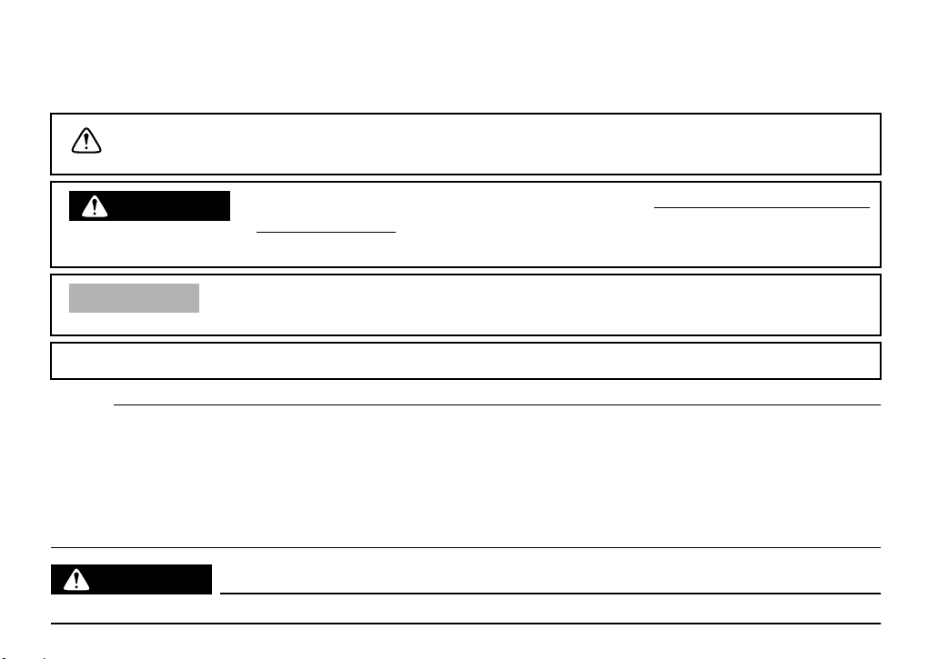
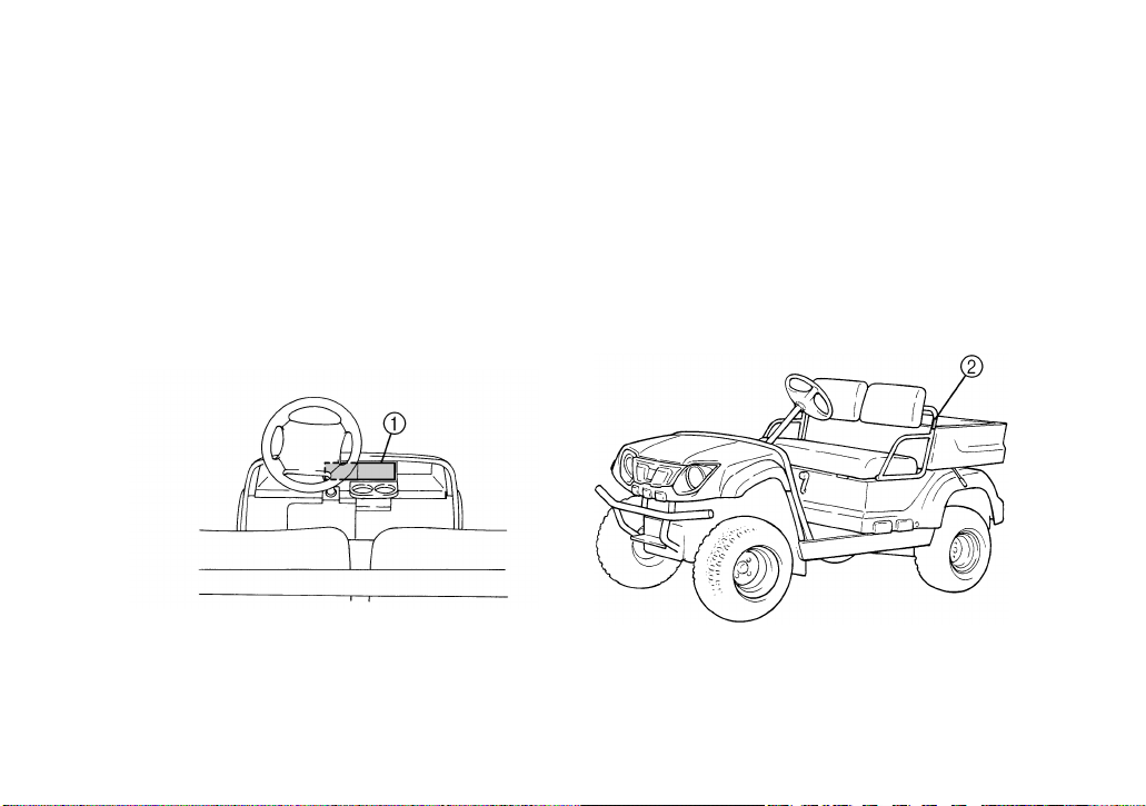
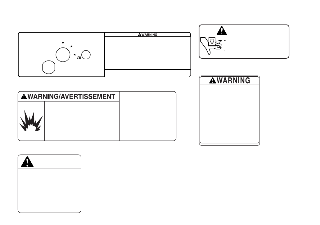
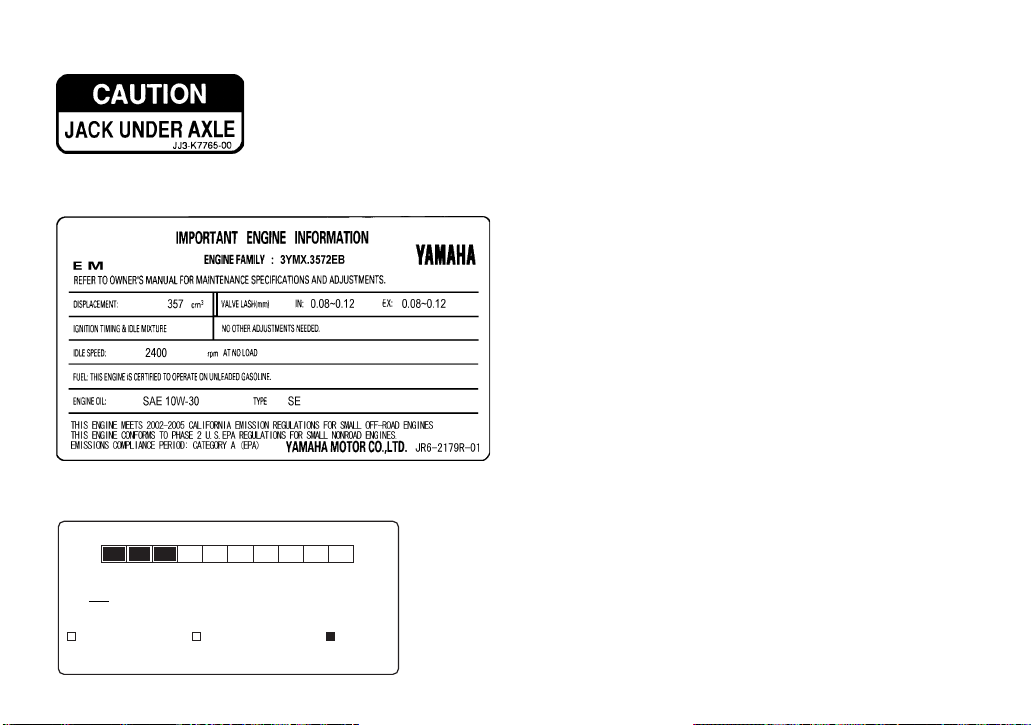
LOCATION OF THE WARNING AND
SPECIFICATION LABELS
Read and understand all of the labels on your vehicle. They contain important information for safe
and proper operation of your vehicle.
Never remove any labels from your vehicle. If a label becomes difficult to read or comes off, a replacement label is available from your Yamaha dealer.
YXP700
1-1
Page 11
9
1
2
3
4
5
6
7
8
9
10
11
12
1-2
0
13
14
Page 12
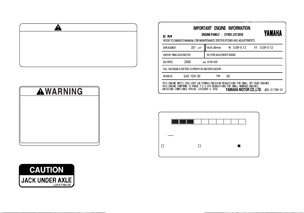
YXP700
Do not temper
with governor
to increase
speed. Operation
at higher speeds
can cause loss
of control that
can result in
severe injury or
death.
Ne pas toucher au
r égulateur afin
d ’augmenter la
vitesse. Un
fonctionnement
à des vitesses
supé rieures au
r églage initial
peut causer une
perte de contrô le
qui peut mener
à une blessure
grave, voire
fatale.
YAMAHA JN3-K8299-10
WARNING
AVERTISSEMENT
YAMAHA JU7-F1696-00
IMPROPER TIRE PRESSURE OR OVERLOADING CAN CAUSE
LOSS OF CONTROL.
LOSS OF CONTROL CAN RESULT IN SEVERE INJURY OR
DEATH.
OPERATING TIRE PRESSURE: Set with tires cold.
RECOMMENDED: 84 kPa, {.84 kgf/cm}, 12 psi
MINIMUM: 70 kPa, {.70 kgf/cm}, 10 psi
Never set tire pressure below minimum. Tire may
dislodge from rim.
Vehicle Rated Capacity: 700 lb (318 kg)
maximum including weight of operator,
passenger, accessories, cargo, and
(if applicable) trailer tongue weight.
1
OFF
3
• Gasoline is
extremely
flammable.
• Keep heat, sparks
and open flame
away from fuel
tank and fuel lines.
• Do not add fuel
while engine is
running or hot.
• Do not modify fuel
system. Service
should be performed
by dealer or
qualified personnel.
4
ON
ON
OIL
WARNING
JU7-K7761-00YAMAHA
• L’essence est
exstrêmement inflammable.
• Garder étincelles, flammes
et chaleur loin du
ré servoir à essence et
des tuyaux à carburant.
• Ne pas ajouter d’essence
pendant que le moteur
est en marche ou quand le
moteur est chaud.
• Ne pas modifier le système
d’ alimentation. Toute
ré vision doit être faite
chez le fournisseur ou
par du personnel qualifié.
Improper use can result in SEVERE INJURY or DEATH
• Vehicle capacity: 1 operator and 1 passenger.
• Remain seated and hold on while in motion.
• This vehicle is recommended only for operators 16 and older
with a valid motor vehicle license. Adults must supervise use
by minors. Check state laws for minimum age requirements.
• Drive slowly in turns.
• Drive straight up and down hills-driving across the side of a
hill increases the risk of overturn.
• Keep entire body inside vehicle.
• Passenger and cargo can affect vehicle handling.
• Vehicle rated capacity (driver, passenger, cargo, trailer, and
load) 700 lb. (318 kg) on level surface.
LOCATE AND READ OWNER’S MANUAL. FOLLOW ALL INSTRUCTIONS AND WARNINGS.
This vehicle was not manufactured for use on public streets and does
not comply with federal motor vehicle safety standards applicable to
passenger cars.
USE REGULAR
UNLEADED
GASOLINE
ONLY
Motor Oil
Requirements:
• Use only SAE
• Maintain oil
YAMAHA JN3-K8297-10
10W-30, API
service SE or
SF.
level between
dipstick “MIN”
and “MAX” marks.
ATTENTION
UTILISER
UNIQUEMENT
DE L’ESSENCE
SANS PLOMB
Pour l’huile du
moteur, il faut:
• Utiliser
uniquement
SAE 10W-30, API
service SE ou SF.
• Garder le niveau
d’huile entre les
marques “MIN” et
“MAX” indiquées
sur la jauge de
niveau d’huile.
1-3
2
WARNING
Keep hands, body, other
persons away when closing bed.
Do not operate the vehicle
YAMAHA 5UG-K7764-00
5
with bed up.
Page 13
6
9
Severe INJURY or DEATH can result if you ignore the following:
• Maximum Load in Cargo Bed: 250 lb. (113 kg).
• Never carry passengers or fill fuel containers in cargo bed.
• Cargo can affect handling and stability. Read Owner’s Manual before loading or towing.
• When loading with cargo or towing a trailer: Reduce speed and allow more room to stop.
Avoid hills and rough terrain.
• Be sure cargo is secured—a loose load could change handling unexpectedly.
• Keep weight in the cargo bed centered, and as low and far forward as possible.
Top-heavy loads increase the risk of overturn.
YAMAHA
WARNING
JU7-K7766-01
7
Improperly loading a trailer and failure to use extra care
when pulling trailer can cause an accident or injury.
Never load more than 68 kg (150 lbs) tongue weight on
the towing bracket.
Do not tow more than 227 kg (500 lbs) rolling weight
(trailer plus cargo).
Allow for increased braking distance and use extreme caution
when operating on inclines.
Read carefully the loading information and trailer hitch sections
in the owner’s manual.
YAMAHA JU7-K7768-00
8
0
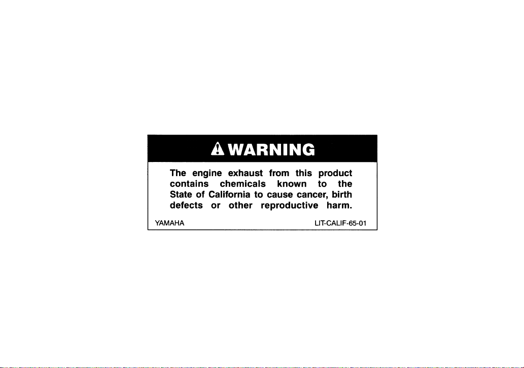
ENGINE AIR INDEX (California only)
0 2 4 6 8 10
MOST CLEAN LEAST CLEAN
NOTE : THE LOWER THE AIR INDEX. THE LESS THE POLLUTION
THIS ENGINE IS CERTIFIED TO BE EMISSION COMPLIANT
FOR THE FOLLOWING USE :
MODERATE
CHECK OWNERS MANUAL FOR FURTHER DETAILS
THIS LABEL TO BE REMOVED BY THE ULTIMATE PURCHASER ONLY
INTERMEDIATE
EXTENDED
1-4
Page 14
YXP1000
7
8
1-5
Page 15
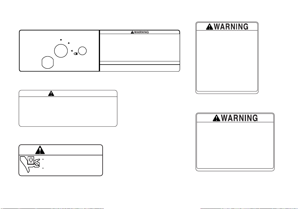
YXP1000
YAMAHA JU9-F1696-00
IMPROPER TIRE PRESSURE OR OVERLOADING CAN CAUSE
LOSS OF CONTROL.
LOSS OF CONTROL CAN RESULT IN SEVERE INJURY OR
DEATH.
OPERATING TIRE PRESSURE: Set with tires cold.
RECOMMENDED: 84 kPa, {.84 kgf/cm}, 12 psi
MINIMUM: 70 kPa, {.70 kgf/cm}, 10 psi
Never set tire pressure below minimum. Tire may
dislodge from rim.
Vehicle Rated Capacity: 1000 lb (454 kg)
maximum including weight of operator,
passenger, accessories, cargo, and
(if applicable) trailer tongue weight.
1
OFF
ON
2
Severe INJURY or DEATH can result if you ignore the following:
• Maximum Load in Cargo Bed: 500 lb. (227 kg).
•
Never carry passengers or fill fuel containers in cargo bed.
•
Cargo can affect handling and stability. Read Owner’s Manual before loading or towing.
• When loading with cargo or towing a trailer: Reduce speed and allow more room to stop.
Avoid hills and rough terrain.
• Be sure cargo is secured—a loose load could change handling unexpectedly.
• Keep weight in the cargo bed centered, and as low and far forward as possible.
Top-heavy loads increase the risk of overturn.
YAMAHA
WARNING
3
YAMAHA 5UG-K7764-00
WARNING
Keep hands, body, other
persons away when closing bed.
Do not operate the vehicle
with bed up.
ON
WARNING
4
Improper use can result in SEVERE INJURY or DEATH
• Vehicle capacity: 1 operator and 1 passenger.
• Remain seated and hold on while in motion.
• This vehicle is recommended only for operators 16 and older
with a valid motor vehicle license. Adults must supervise use
by minors. Check state laws for minimum age requirements.
• Drive slowly in turns.
• Drive straight up and down hills-driving across the side of a
hill increases the risk of overturn.
• Keep entire body inside vehicle.
• Passenger and cargo can affect vehicle handling.
OIL
• Vehicle rated capacity (driver, passenger, cargo, trailer, and
load) 1000 lb. (454 kg) on level surface.
LOCATE AND READ OWNER’S MANUAL. FOLLOW ALL INSTRUCTIONS AND WARNINGS.
This vehicle was not manufactured for use on public streets and does
not comply with federal motor vehicle safety standards applicable to
passenger cars.
JU9-K7761-00YAMAHA
ATTENTION
5
JU9-K7766-01
1-6
Improperly loading a trailer and failure to use extra care
when pulling trailer can cause an accident or injury.
Never load more than 68 kg (150 lbs) tongue weight on
the towing bracket.
Do not tow more than 454 kg (1000 lbs) rolling weight
(trailer plus cargo).
Allow for increased braking distance and use extreme caution
when operating on inclines.
Read carefully the loading information and trailer hitch sections
in the owner’s manual.
YAMAHA JU5-K7768-00
Page 16
6
7
8
ENGINE AIR INDEX (California only)
0 2 4 6 8 10
MOST CLEAN LEAST CLEAN
NOTE : THE LOWER THE AIR INDEX. THE LESS THE POLLUTION
THIS ENGINE IS CERTIFIED TO BE EMISSION COMPLIANT
FOR THE FOLLOWING USE :
MODERATE
CHECK OWNERS MANUAL FOR FURTHER DETAILS
THIS LABEL TO BE REMOVED BY THE ULTIMATE PURCHASER ONLY
INTERMEDIATE
EXTENDED
1-7
Page 17
1-
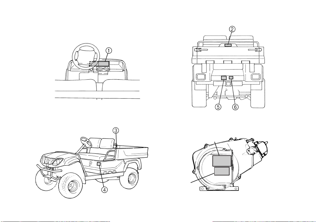
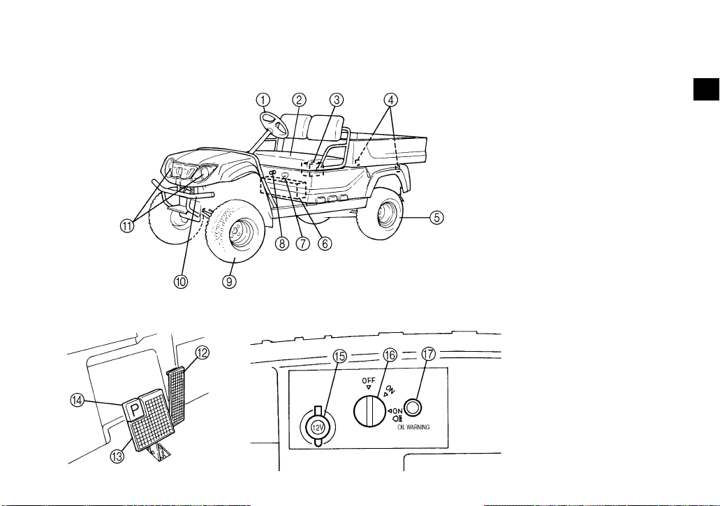
DESCRIPTION AND VEHICLE IDENTIFICATION
FEATURES
1. Steering wheel
2. Seat
3. Battery
4. Taillight
5. Rear tire
6. Fuel tank
7. Drive select lever
8. Starter (choke)
9. Front tire
10. Front bumper
11. Headlight
12. Accelerator pedal
13. Brake pedal
14. Parking brake pedal
15. Auxiliary DC jack
16. Main switch
17. Oil level warning light
1
2
3
4
5
6
7
8
9
10
11
12
13
14
2-1
Page 18
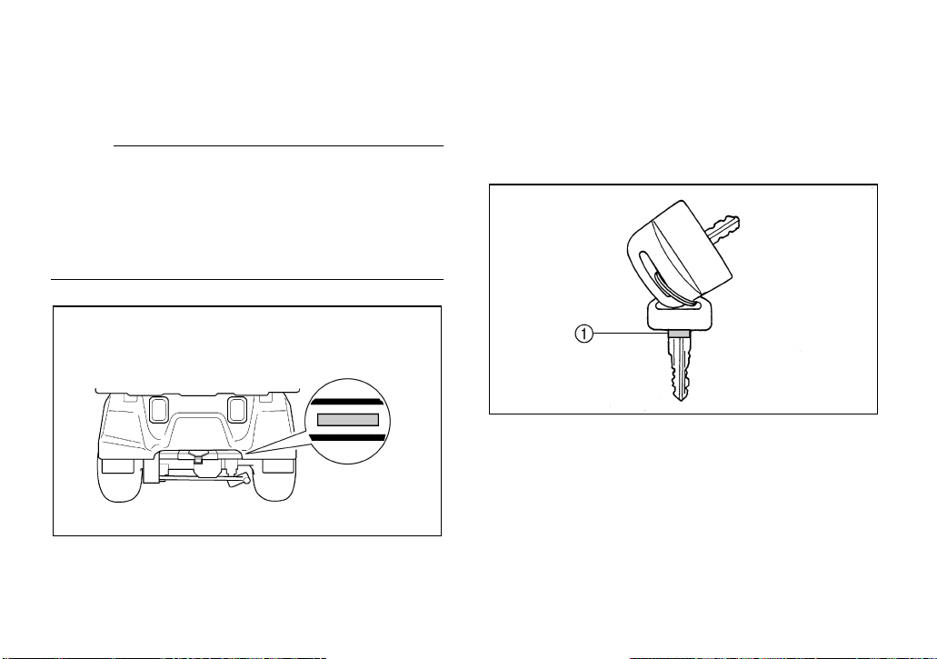
Utility vehicle serial number
The utility vehicle serial number is stamped in
the location shown.
NOTE:
The first three digits of the serial number are
for model identification; the remaining digits
are the unit production number. Keep a record
of these numbers for reference when ordering
parts from a Yamaha dealer.
Key identification number
The key identification number is stamped on
the key as shown in the following illustration.
This number can be used for ordering a new
key.
1. Key identification number
2-2
Page 19
SAFETY INFORMATION
1
SEVERE INJURY OR DEATH can result if
you do not follow these instructions:
●
Read this manual and all labels carefully
and follow the operating procedures described.
●
This vehicle is designed to carry the driver
and one passenger. Never carry passengers in the cargo bed.
●
Never give a ride to a passenger who is unable to put both feet firmly on the floorboard
while seated with his or her back against
the backrest. The passenger must hold on
to the grab rail at all times while the vehicle
is in motion.
●
Never operate this vehicle on any public
street, road, or highway, even a dirt or gravel one.
●
Never consume alcohol or drugs before or
while operating this vehicle.
●
Never operate at speeds too fast for your
skills or the conditions. Always go at a
speed that is proper for the terrain, visibility,
and operating conditions, and your experience.
●
Never attempt jumps or other stunts.
●
Always inspect your vehicle each time you
use it to be sure it is in safe operating condition. Always follow the inspection and
maintenance procedures and schedules
described in this manual.
●
Always keep both hands, arms, feet, and
legs inside the vehicle at all times during
operation. Keep your feet on the floorboard.
●
Always keep both hands on the steering
wheel when driving.
3-1
2
3
4
5
6
7
8
9
10
11
12
13
14
Page 20

●
Always go slowly and be extra careful when
operating on unfamiliar terrain. Always be
alert to changing terrain conditions when
driving the vehicle.
●
Never operate on excessively rough, slippery, or loose terrain.
●
Never turn at excessive speed. Practice
turning at slow speeds before attempting to
turn at faster speeds. Do not attempt turns
on steep slopes.
●
Never operate the vehicle on slopes that
are too steep for it or for your abilities. Go
straight up and down slopes where possible.
●
Never operate on slopes that are slippery
or ones where you will not be able to see
far enough ahead of you. Never go over the
top of a slope at speed if you cannot see
what is on the other side.
●
Always check terrain carefully before going
down slopes. Go as slowly as possible.
Never go down a slope at high speed.
●
Always check for obstacles before operating in a new area.
●
Never operate the vehicle in fast flowing
water or water deeper than 15 cm (6 in).
Remember that wet brakes may have reduced stopping ability. Test your brakes after leaving water. If necessary, apply them
several times to let friction dry out the linings.
●
Always be sure there are no obstacles or
people behind you when you operate in reverse. When it is safe to proceed in reverse, go slowly. Do not brake abruptly
when carrying loads in the cargo bed.
●
Always use the size and type of tires specified in this manual.
●
Always maintain proper tire pressure as described in this manual.
3-2
Page 21

●
Never exceed the stated load capacity.
Cargo should be as far forward in the bed
as possible, and distributed evenly from
side to side. Be sure cargo is secured so
that it cannot move around during operation. Reduce speed and follow instructions
in this manual for carrying cargo or pulling a
trailer. Allow greater distance for braking.
3-3
Page 22
CONTROL FUNCTIONS
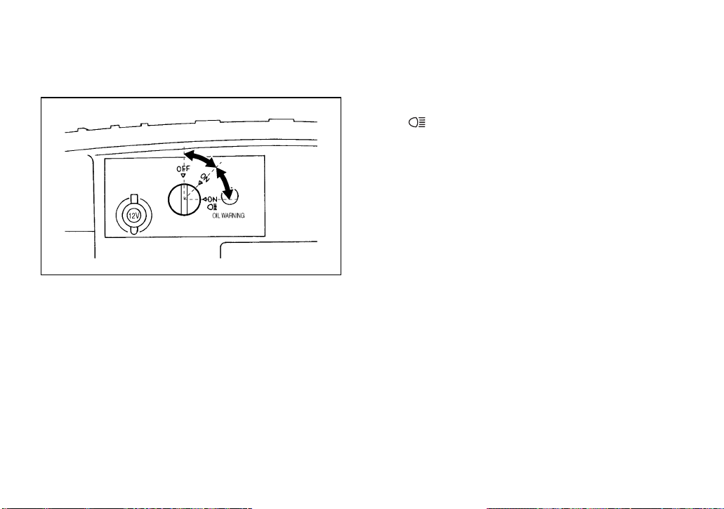
Main switch
The main switch positions are as follows:
OFF:
All electrical circuits are switched off. The key
can be removed in this position only.
ON:
All electrical circuits (except for the headlights
and taillights) are switched on.
The utility vehicle can be operated.
ON :
All electrical circuits are switched on.
The headlights and taillights come on.
The utility vehicle can be operated.
4-1
Page 23
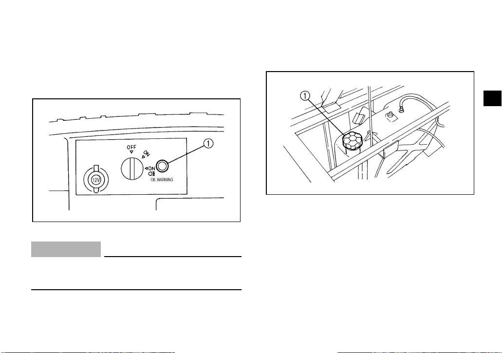
Oil level warning light
This warning light comes on when the engine
oil level is low.
If the light comes on, stop
the engine, check the engine oil level, and
add oil as necessary. (See page 8-9–8-10).
Fuel tank cap
Remove the fuel tank cap by turning it counterclockwise.
1. Fuel tank cap
1
2
3
4
5
6
7
8
9
10
1. Oil level warning light
CAUTION:
Always make sure there is enough engine
oil before starting the engine.
11
12
13
14
4-2
Page 24
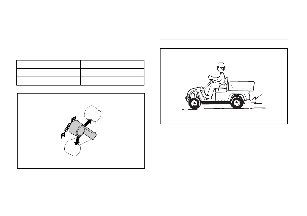
Drive select lever
The drive select lever is used for driving the
utility vehicle either forward or in reverse.
After coming to a complete stop, shift the lever
to the desired position.
Lever position Vehicle movement
FFORWARD
R REVERSE
NOTE:
The back-up buzzer will sound when the drive
select lever is shifted to “R.”
4-3
Page 25
Accelerator pedal
1
The accelerator pedal controls the utility vehicle’s speed.
Action Vehicle speed
Depress pedal Increase
Release pedal Decrease
1
1. Accelerator pedal
NOTE:
The engine does not start until the accelerator
pedal is depressed.
Brake pedal
Press the brake pedal down to slow or stop
the utility vehicle.
1. Brake pedal
NOTE:
The engine stops when the utility vehicle
comes to a complete stop.
4-4
Page 26
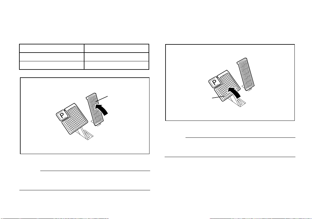
Parking brake pedal
1
Press the parking brake pedal down whenever parking the utility vehicle.
1
1. Parking brake pedal
NOTE:
Release the parking brake by depressing the
accelerator pedal.
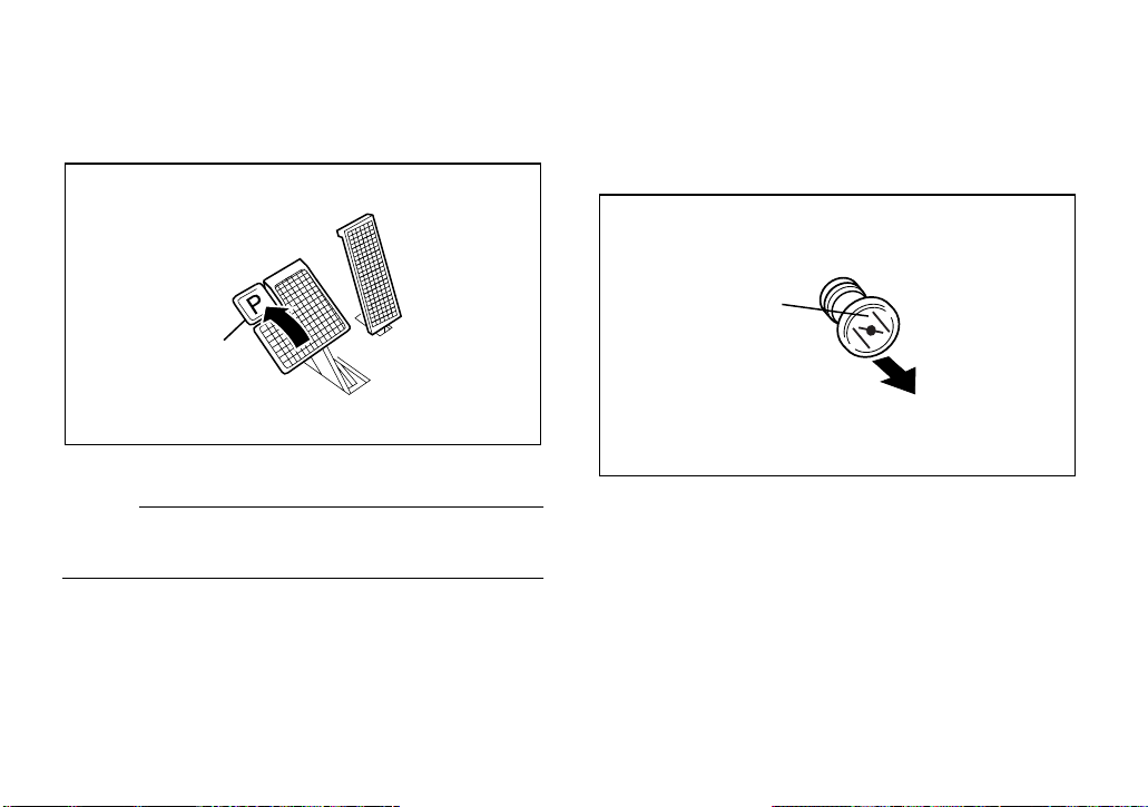
Starter (choke)
Pull the starter (choke) knob out and hold it
when starting a cold engine. Release it after
the engine starts.
1. Starter (choke) knob
4-5
Page 27
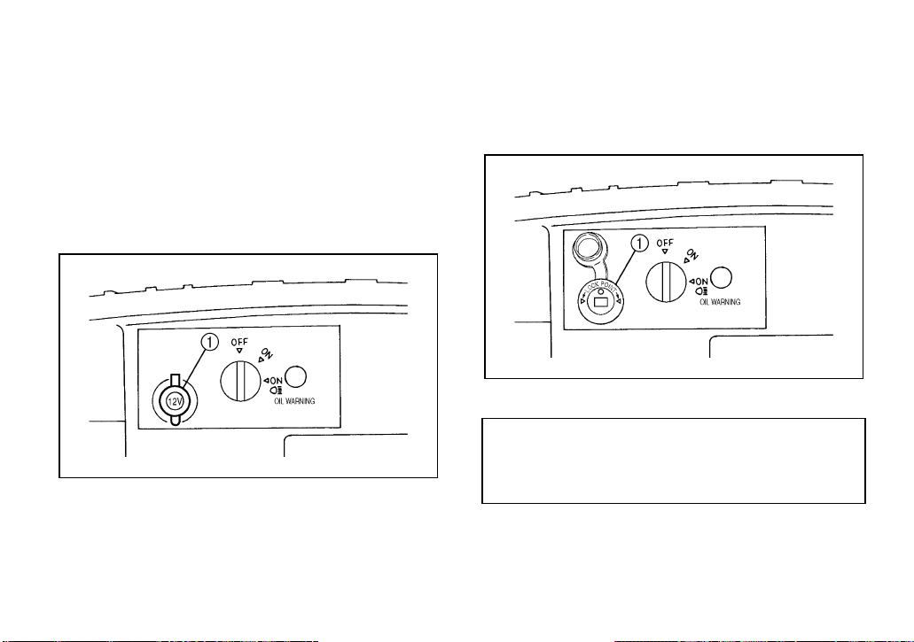
Auxiliary DC jack
The auxiliary DC jack is located in the front
panel.
The auxiliary DC jack can be used for accessories such as lights, radios, etc.
The auxiliary DC jack should only be used for
short periods if the utility vehicle is not being
operated.
1. Auxiliary DC jack cap
1. Set the main switch to “ON”.
2. Open the auxiliary DC jack cap, and then
insert the accessory power plug into the
jack.
1. Auxiliary DC jack
Maximum rated capacity for the auxiliary
DC jack:
DC 12 V, 120 W (10 A)
3. Close the auxiliary DC jack cap if the jack
is not being used.
4-6
Page 28
CAUTION:
Do not use accessories requiring
●
more than the maximum rated capacity for the auxiliary DC jack. This may
overload the circuit and cause the
fuse to blow.
If accessories are used for extended
●
periods when the utility vehicle is not
being operated or with the main
switch set to “ON ”, the battery
will lose its charge and starting the
engine may become difficult.
Do not use an automotive cigarette
●
lighter or other accessories with a
plug that get hot because the jack can
be damaged.
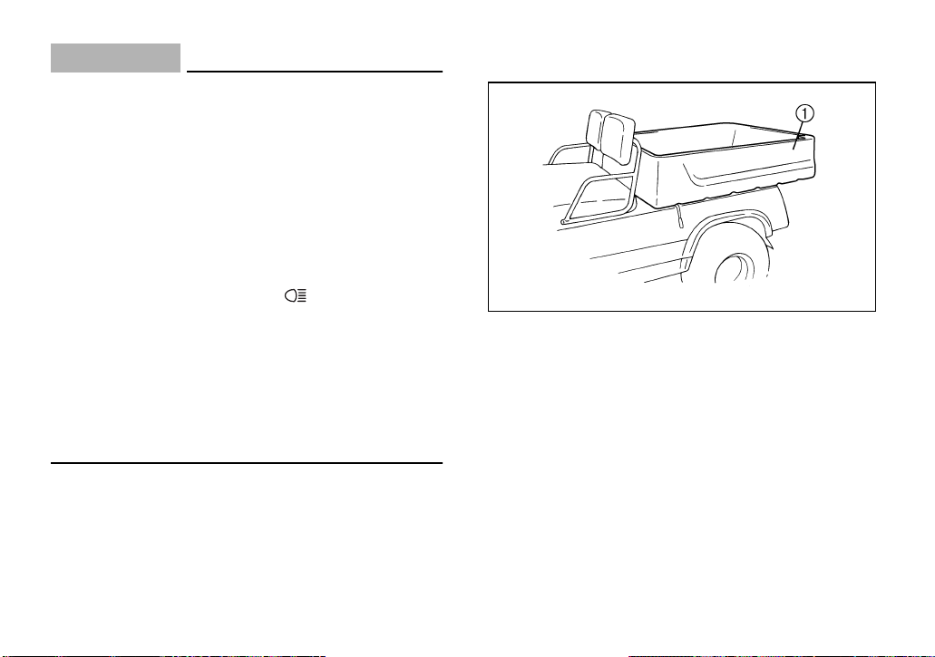
Cargo bed
1. Cargo bed
4-7
Page 29

Opening and closing the tailgate
(For YXP1000)
1. Tailgate 2. Latch (× 2)
To open:
Unhook the latches, and then lower the tailgate.
To close:
Place the tailgate in its original position, and
then hook the latches.
Lifting and lowering the cargo bed
1. Cargo bed release lever
4-8
1. Prop rod
Page 30

To lift:
Pull the cargo bed release lever towards the
rear, and then slowly lift up the cargo bed until
end of the prop rod hooks onto the prop rod
guide to support the cargo bed.
To lower:
Slightly lift up the cargo bed, unhook the end
of the prop rod, and then lower the cargo bed
slowly to its original position. Make sure that
the latch for the cargo bed is properly engaged.
Maximum load limit:
113 kg (250 lb) (YXP700)
227 kg (500 lb) (YXP1000)
WARNIN G
POTENTIAL HAZARD
Overloading the cargo bed.
WHAT CAN HAPPEN
Could cause changes in vehicle handling which could lead to an accident.
HOW TO AVOID THE HAZARD
Never exceed the stated maximum load
for this cargo bed.
Cargo should be properly distributed.
Reduce speed when carrying cargo. Allow greater distance for braking.
4-9
Page 31

WARNIN G
WARNIN G
POTENTIAL HAZARD
Carrying a passenger in the cargo bed.
WHAT CAN HAPPEN
The passenger could fall, be thrown out,
or be struck by objects in the cargo bed.
HOW TO AVOID THE HAZARD
Never carry a passenger. This cargo
bed is designed to carry cargo only.
POTENTIAL HAZARD
Pinch point.
WHAT CAN HAPPEN
You or someone else could be pinched
between the cargo bed and the frame or
the seat backs when the bed is being
lowered.
HOW TO AVOID THE HAZARD
Before closing the cargo bed, be sure
others are standing away from the utility
vehicle and that no one is sitting on the
seat. Keep hands and fingers away from
the space between the cargo bed and
seat backs.
4-10
Page 32

WARNIN G
POTENTIAL HAZARD
Fire or explosion while filling a portable
fuel container.
WHAT CAN HAPPEN
Static electricity sparks can ignite fuel
vapors. The plastic bed is not grounded,
increasing the risk of static electricity
build-up.
HOW TO AVOID THE HAZARD
Do not refill fuel containers in the plastic
bed. Set fuel container on the ground
and touch the nozzle to the container
before removing the container cap.
Keep nozzle in contact with can inlet
when filling. Tighten cap before putting
fuel container in cargo bed.
Trailer hitch bracket
This vehicle is equipped with a 5 cm (2 in) receiver bracket for a standard trailer hitch.
Trailer towing equipment can be obtained at a
Yamaha dealer. (See page 6-5 for precaution
information.)
1. Trailer hitch bracket
4-11
Page 33

1-
PRE-OPERATION CHECKS
Pre-operation checks should be made each
time you use your utility vehicle. Get in the
habit of performing the following checks in the
same way so that they become second nature.
WARNIN G
POTENTIAL HAZARD
Failure to inspect the vehicle before operating. Failure to properly maintain the
vehicle.
WHAT CAN HAPPEN
Increases the possibility of an accident
or equipment damage.
HOW TO AVOID THE HAZARD
Always inspect your vehicle each time
you use it to make sure the vehicle is in
safe operating condition. Always follow
the inspection and maintenance procedures and schedules described in the
Owner’s Manual.
1
2
3
4
5
6
7
8
9
10
11
12
13
14
5-1
Page 34

Pre-operation check list
Before using this vehicle, check the following points:
ITEM ROUTINE PAGE
Brakes
Parking brake
Fuel
Engine oil
Transmission oil
Accelerator pedal
Steering
Fittings and fasteners
Lights and switches
Wheels and tires
• Check for proper operation, condition and free play. 5-3, 8-20–8-22
• Check for proper operation, condition and free play. 5-3, 8-20–8-22
• Check fuel level.
• Fill with fuel if necessary.
• Check oil level.
• Fill with oil if necessary.
• Check for leakage. 5-5, 8-17–8-18
• Check for proper accelerator pedal operation. 5-6
• Check for proper operation. 5-6
• Check all fittings and fasteners. 5-6
• Check for proper operation. 5-6, 8-22–8-24
• Check tire pressure, wear and damage. 5-7–5-9, 8-18–8-19
5-4–5-5
5-5, 8-9–8-10
5-2
Page 35

Brakes
Brake pedal
Check for correct brake pedal free play. If the
brake pedal free play is incorrect, have a
Yamaha dealer adjust it. (See pages 8-20–
8-22.)
Check the operation of the brake pedal. It
should move smoothly and there should be a
firm feeling when the brakes are applied. If
not, have the vehicle inspected by a Yamaha
dealer.
Brake operation
Test the brakes at slow speed after starting
out to make sure they are working properly. If
the brakes do not provide proper braking performance, inspect the brake system. (See
pages 8-20–8-22.)
WARNIN G
POTENTIAL HAZARD
Driving with improperly operating
brakes.
WHAT CAN HAPPEN
You could lose braking ability, which
could lead to an accident.
HOW TO AVOID THE HAZARD
Always check the brakes at the start of
every ride. Do not operate the vehicle if
you find any problem with the brakes. If
a problem cannot be corrected by the
adjustment procedures provided in this
manual, have the vehicle inspected by a
Yamaha dealer.
5-3
Page 36

Fuel
Make sure there is sufficient gasoline in the
tank.
Recommended fuel:
UNLEADED GASOLINE ONLY
Fuel tank capacity:
24.0 L
(5.3 Imp gal, 6.3 US gal) (YXP700)
30.0 L
(6.6 Imp gal, 7.9 US gal) (YXP1000)
CAUTION:
_
Use only unleaded gasoline. The use of
leaded gasoline will cause severe damage
to internal engine parts, such as the valves
and piston rings, as well as to the exhaust
system.
_
Your Yamaha engine has been designed to
use regular unleaded gasoline with a pump
octane number ([R+M]/2) of 86 or higher, or
research octane number of 91 or higher. If
knocking or pinging occurs, use a different
brand of gasoline or premium unleaded fuel.
Unleaded fuel will give you longer spark plug
life and reduced maintenance cost.
Gasohol
There are two types of gasohol; gasohol containing ethanol and that containing methanol.
Gasohol containing ethanol can be used if
ethanol content does not exceed 10%. Gasohol containing methanol is not recommended
by Yamaha because it may cause fuel system
damage or vehicle performance problems.
5-4
Page 37

WARNIN G
POTENTIAL HAZARD
Improper care when refueling.
WHAT CAN HAPPEN
Fuel can spill, which can cause a fire
and severe injury.
Fuel expands when it heats up. If the
fuel tank is overfilled, fuel could spill out
due to heat from the engine or the sun.
HOW TO AVOID THE HAZARD
Do not overfill the fuel tank. Be careful
not to spill fuel, especially on the engine
or exhaust pipe. Wipe up any spilled fuel
immediately. Be sure the fuel tank cap is
closed securely.
Engine oil
Make sure that the engine oil is at the specified level. Add oil if necessary. (See pages
8-9–8-10 for details.)
CAUTION:
Make sure that no foreign material enters
the crankcase.
Recommended engine oil type and
quantity:
See page 10-3.
Transmission oil
Make sure the transmission oil is at the specified level. Add oil as necessary. (See pages
8-17–8-18 for details.)
Recommended oil:
SAE 90 gear oil
5-5
Page 38

Accelerator pedal
Remove the key from the main switch.
Make sure that the accelerator pedal operates
properly. It must operate smoothly and fully
spring back when released. If the accelerator
pedal does not operate properly, have a
Yamaha dealer check the pedal.
WARNIN G
POTENTIAL HAZARD
Checking operation of the accelerator
pedal with the key in the main switch.
WHAT CAN HAPPEN
The engine can start and the vehicle can
start moving when the accelerator pedal
is depressed.
HOW TO AVOID THE HAZARD
Remove the key from the main switch
before checking accelerator pedal operation.
Steering
Park on level ground. Turn the steering wheel
to the right and left. Check for excessive free
play, abnormal noises, or a rough feeling. If
the steering does not operate properly, have a
Yamaha dealer check the steering.
Fittings and fasteners
Always check the tightness of chassis fittings
and fasteners before a ride. Take the utility
vehicle to a Yamaha dealer or refer to the Service Manual for the correct tightening torques.
Lights
Check the headlights and taillights to make
sure they are in working condition. Repair as
necessary for proper operation.
Switches
Check the operation of all switches. Have a
Yamaha dealer repair as necessary for proper
operation.
5-6
Page 39

Tires
Checking the tire pressure
Use a tire pressure gauge to measure the tire
pressure.
NOTE:
Measure the tire pressure twice and use the
second reading. Dust or dirt in the gauge
could cause the first reading to be incorrect.
WARNIN G
POTENTIAL HAZARD
Operating this vehicle with improper
tires, or with improper or uneven tire
pressure.
WHAT CAN HAPPEN
Use of improper tires on this vehicle, or
operation of this vehicle with improper
or uneven tire pressure, may cause loss
of control, increasing your risk of accident.
HOW TO AVOID THE HAZARD
1. The tires listed below have been approved by Yamaha Motor Manufacturing Corporation of America for
this model. Other tire combinations
are not recommended.
YXP700
Manufacturer Size
Front DURO 20 × 10-8 / 4 PLY
Rear DURO 20 × 10-8 / 4 PLY
5-7
Page 40

YXP1000
Manufacturer Size
Front DURO 22 × 11-10 / 6 PLY
Rear DURO 22 × 11-10 / 6 PLY
2. The tires should be set to the recommended pressure:
●
Recommended tire pressure
Front 84 kPa (0.84 kgf/cm
Rear 84 kPa (0.84 kgf/cm
2
, 12 psi)
2
, 12 psi)
Check and adjust tire pressures when
the tires are cold.
Tire pressures must be equal on both
sides.
3. Tire pressure below the minimum
specified could cause the tire to
dislodge from the rim under severe
riding conditions. The following are
minimums:
Front 70 kPa (0.70 kgf/cm
Rear 70 kPa (0.70 kgf/cm
2
, 10 psi)
2
, 10 psi)
4. Use no more than the following
pressures when seating the tire
beads.
Front 250 kPa (2.5 kgf/cm
Rear 250 kPa (2.5 kgf/cm
2
, 36 psi)
2
, 36 psi)
Higher pressures may cause the
tire to burst. Inflate the tires very
slowly and carefully. Fast inflation
could cause the tire to burst.
5-8
Page 41

Tire wear limit
When the tire groove decreases to 3 mm
(0.12 in) due to wear, replace the tire.
a. Tire wear limit
5-9
Page 42

1-
OPERATION
Starting a cold engine
1. With the parking brake applied, shift the
drive select lever to “F” for forward, or “R”
for reverse.
CAUTION:
Do not shift from “F” forward to “R” re-
verse while the utility vehicle is moving.
2. Turn the main switch to “ON” or “ON ”.
WARNIN G
POTENTIAL HAZARD
Depressing accelerator pedal while
turning on the main switch.
WHAT COULD HAPPEN
The utility vehicle could start moving
unexpectedly.
HOW TO AVOID THE HAZARD
Keep foot away from accelerator pedal
while turning on the main switch.
6-1
Page 43

3. Pull the starter (choke) knob out and hold
1
it while starting a cold engine. Release
the starter (choke) knob after the engine
starts.
1
4. Check that your path is clear in the direction you plan to go, and slowly depress
the accelerator pedal.
The engine will start and the utility vehicle
will start to move.
1
2
3
4
5
6
7
8
9
1. Starter (choke) knob
NOTE:
The choke is not required when the engine is
warm.
1. Accelerator pedal
NOTE:
The parking brake automatically releases
when the accelerator pedal is depressed.
6-2
10
11
12
13
14
Page 44

Starting a warm engine
2
1
To start a warm engine, refer to the “Starting a
cold engine” section. The starter (choke)
should not be used. Press the accelerator
pedal slightly.
Stopping
To stop the utility vehicle, gradually press
down on the brake pedal.
When the utility vehicle has come to a stop,
apply the parking brake pedal and turn the
main switch to “OFF.”
1. Brake pedal 2. Parking brake pedal
CAUTION:
Do not hold the utility vehicle on an incline
with the accelerator – use the brake.
6-3
Page 45

Accessories and loading
Accessories
Accessories can affect the handling and control of your vehicle. Keep the following in mind
when considering an accessory or operating a
vehicle which has accessories.
●
Choose only accessories designed for your
vehicle. Your Yamaha dealer has a variety
of genuine Yamaha accessories. Other accessories may also be available on the
market. However, it is not possible for
Yamaha to test all non-Yamaha accessories, nor have any control over the quality or
suitability of them. Choose a genuine
Yamaha accessory, or one that is equivalent in design and quality.
●
Accessories should be rigidly and securely
mounted. An accessory which can shift position or come off while you are operating
could affect your ability to control the vehicle.
●
Do not mount an accessory where it could
interfere with your ability to control the vehicle. Examples include (but are not limited
to) an object that limits your ability to turn
the steering wheel or one that limits your
view.
●
Use extra caution when driving a vehicle
with accessories. The vehicle may handle
differently than it does without accessories.
6-4
Page 46

EBU09600
Loading
Cargo or a trailer can change the stability and
handling of a vehicle.
You must use common sense and good judgment when carrying cargo or towing a trailer.
Keep the following points in mind:
●
Never exceed the weight limits shown. An
overloaded vehicle can be unstable.
MAXIMUM LOADING LIMIT
●
Maximum cargo bed load:
113 kg (250 lb) (YXP700)
227 kg (500 lb) (YXP1000)
●
Tow hitch
Tow weight (Including driver,
passenger, vehicle cargo and trailer
and trailer cargo):
227 kg (500 lb) (YXP700)
454 kg (1000 lb) (YXP1000)
Tongue weight: 68 kg (150 lb)
●
Choose a trailer hitch drawbar designed for
use with a 5 cm (2 in) receiver. (See page
4-11 for more information.)
●
Do not exceed the maximum tongue
weight. You can measure tongue weight
with a bathroom scale. Put the tongue of
the loaded trailer on the scale with the
tongue at hitch height. Adjust the load in the
trailer, if necessary, to reduce the weight on
hitch. If you are carrying cargo and towing a
trailer, include the tongue weight in the
maximum vehicle load limit.
●
Load cargo in the cargo bed as close to the
center of the vehicle as possible.
●
Tie down cargo securely in the trailer. Make
sure cargo in the trailer cannot move
around. A shifting load can cause an accident.
6-5
Page 47

●
Make sure the load does not interfere with
controls or your ability to see where you are
going.
●
Drive more slowly than you would without a
load. The more weight you carry, the slower you should go. Although conditions vary,
it is good practice not to exceed low range
whenever you are carrying heavier loads or
when towing a trailer.
●
Allow more braking distance. A heavier vehicle takes longer to stop.
●
Avoid making sharp turns unless at very
slow speeds.
●
Avoid hills and rough terrain. Choose terrain carefully. Added weight affects the stability and handling of the vehicle.
WARNIN G
POTENTIAL HAZARD
Overloading this vehicle or carrying or
towing cargo improperly.
WHAT CAN HAPPEN
Could cause changes in vehicle handling which could lead to an accident.
HOW TO AVOID THE HAZARD
Never exceed the stated load capacity
for this vehicle.
Cargo should be properly distributed
and securely attached.
Reduce speed when carrying cargo or
pulling a trailer. Allow greater distance
for braking.
6-6
Page 48

1-
DRIVING YOUR VEHICLE
WARNIN G
GETTING TO KNOW YOUR VEHICLE
This off-highway utility vehicle will handle and
maneuver differently from an ordinary passenger car or other vehicle.
Before you begin to use your vehicle, be sure
you have read this Owner’s Manual completely and understand the operation of the controls. Pay particular attention to the safety
information on pages 3-1–3-3. Please also
read all caution and warning labels on your
vehicle.
This vehicle is designed for the operator and
one passenger. Never carry passengers in
the cargo bed.
POTENTIAL HAZARD
Carrying a passenger in the cargo bed.
WHAT CAN HAPPEN
The passenger could fall or be struck by
objects in the cargo bed.
HOW TO AVOID THE HAZARD
Never carry a passenger in the cargo
bed. The cargo bed is designed to carry
cargo only.
7-1
Page 49

Carrying a passenger and cargo can affect
vehicle handling.
The total weight of operator, passenger, accessories, cargo, trailer tongue weight, and
the vehicle itself must not exceed the maximum load limit.
Maximum load limit:
318 kg (700 lb) (YXP700)
454 kg (1000 lb) (YXP1000)
WARNIN G
POTENTIAL HAZARD
Overloading this vehicle or carrying or
towing cargo improperly.
WHAT CAN HAPPEN
Could cause changes in vehicle handling which could lead to an accident.
HOW TO AVOID THE HAZARD
Never exceed the stated load capacity
for this vehicle.
Cargo should be properly distributed
and securely attached.
Reduce speed when carrying cargo or
pulling a trailer. Allow greater distance
for braking.
Remain seated and hold on when the vehicle
is in motion. Keep hands and feet inside the
vehicle at all times.
1
2
3
4
5
6
7
8
9
10
11
12
13
14
7-2
Page 50

LEARNING TO OPERATE YOUR VEHICLE
You should become familiar with the performance characteristics of the vehicle in a large,
flat area that is free of obstacles and other vehicles. Practice control of the accelerator,
brakes, steering, and forward/reverse select
lever. Drive first at slow speed and become
comfortable at that speed before gradually increasing your speed. Take the time to learn
basic operation before attempting more difficult maneuvers.
Set the parking brake. Perform the Pre-Operation Checks on pages 5-2. If the engine is
cold, pull out the choke knob. To start the engine, press the accelerator pedal slowly and
smoothly. The centrifugal clutch will engage
and you will start to accelerate. Avoid higher
speeds until you are thoroughly familiar with
the operation of your vehicle. Push in the
choke knob after the engine has warmed.
When slowing down or stopping, take your
foot off the accelerator pedal and smoothly
press the brake pedal. Improper use of the
brakes can cause the tires to lose traction, reducing control and increasing the possibility of
an accident. The engine stops running when
the vehicle stops.
TURNING YOUR VEHICLE
It is possible for the vehicle to roll over or go
out of control if you attempt sharp, higher
speed turns. You should also be careful making sharp turns on rough terrain. Do not attempt to turn around or make abrupt
maneuvers on slopes.
BRAKING
Braking ability is affected by the type of terrain. In most cases, gradual application of the
brakes is more effective than abrupt braking,
particularly on loose surfaces like gravel. Always allow for greater braking distance on
rough, loose, or slippery surfaces.
7-3
Page 51

GOING UPHILL
Do not attempt to climb slopes until you have
mastered basic maneuvers on flat ground.
Use proper driving techniques to avoid overturns on hills and slopes. Drive straight up
slopes, and avoid crossing the side of a slope,
which increases your chance of rollover.
Practice first on gentle inclines before attempting slopes. Always check the terrain
carefully before attempting any slope. Use
common sense and remember that some
slopes are too steep for you to climb.
Maximum slope angle:
15°
Choose carefully which slopes you attempt to
drive on. Avoid slopes with slippery surfaces
or ones where you will not be able to see far
enough ahead of you.
WARNIN G
POTENTIAL HAZARD
Operating on steep slopes.
WHAT CAN HAPPEN
The utility vehicle can overturn more
easily on steep slopes than on level surfaces or gentle inclines.
HOW TO AVOID THE HAZARD
Never operate your vehicle on slopes
too steep for it or your abilities. Never
operate vehicles on slopes steeper than
15°.
Do not drive across the face of a slope.
Go straight up the slope.
Practice on smaller slopes before attempting large slopes.
Slow down when you reach the crest of the hill
if you cannot clearly see what is on the other
side - there could be another person, an obstacle, or a sharp drop off.
7-4
Page 52

If you start to lose traction or momentum
when going up a slope, and you decide you
will be unable to continue, use the brakes to
come to a stop. Do not attempt to turn the vehicle around. Instead, back down the hill as
slowly as possible, gently applying the brakes
when necessary.
GOING DOWNHILL
Check the terrain carefully before going down
a slope. When possible, choose a path that
lets you drive your vehicle straight downhill.
Carefully choose your path and drive no faster
than you will be able to react to obstacles that
may appear. If you must turn to avoid an obstacle, do not turn at a sharp angle that could
allow the vehicle to pitch or roll over.
WARNIN G
POTENTIAL HAZARD
Going down a slope improperly.
WHAT CAN HAPPEN
Could cause loss of control or cause the
vehicle to overturn.
HOW TO AVOID THE HAZARD
Always check the terrain carefully before you start down any slope. Never go
down a slope at high speed. Avoid going down a slope at an angle that would
cause the vehicle to lean sharply to one
side. Go straight down the slope where
possible.
Go as slowly as possible. If you are starting to
go too fast, apply the brakes gently. Avoid
sudden application of the brakes, which could
cause the vehicle to start sliding.
If you start to slide or skid, try to steer in the direction the vehicle is sliding to help you regain
control.
7-5
Page 53

If you must turn on the slope to avoid an obstacle, do so slowly and carefully. If the vehicle starts to tip, gradually steer in the downhill
direction if there are no obstacles in your path.
As you regain proper balance, gradually steer
again in the direction you want to go.
CROSSING THROUGH SHALLOW WATER
If you must cross shallow, slow moving water
up to 15 cm (6 in), choose your path carefully
to avoid sharp drop-offs, large rocks, or slippery surfaces that could cause the vehicle to
overturn. Never operate through water deeper
than 15 cm (6 in) or fast flowing water.
Wet brakes may have reduced effectiveness.
After leaving the water, test your brakes. If
necessary, apply the brakes several times to
let friction dry out the linings.
WARNIN G
POTENTIAL HAZARD
Operating this vehicle through deep or
fast-flowing water.
WHAT CAN HAPPEN
Loss of control, which could result in an
accident including overturn.
HOW TO AVOID THE HAZARD
Never operate the vehicle in fast flowing
water or in water deeper than 15 cm
(6 in).
Remember that wet brakes may have reduced stopping ability. Test your brakes
after leaving water. If necessary, apply
them several times to let friction dry out
the linings.
7-6
Page 54

ROUGH TERRAIN
Avoid operating over very rough terrain. Look
for obstacles that could cause damage to the
vehicle or could lead to a rollover or accident.
Avoid jumping the vehicle as injury, loss of
control, and damage to the vehicle could occur.
WARNIN G
POTENTIAL HAZARD
Operating in rough terrain.
WHAT CAN HAPPEN
The vehicle can overturn or go out of
control.
HOW TO AVOID THE HAZARD
Always be alert to changing terrain. Go
slowly and be extra careful on unfamiliar terrain, so you will have enough time
to react to hidden rocks, bumps, or
holes in your path.
RIDING IN BRUSH OR WOODED AREAS
When operating in areas with brush or trees,
watch carefully on both sides and above the
vehicle for obstacles such as branches that
the vehicle might hit, causing an accident, or
for brush that might enter the vehicle as you
pass and strike the driver or passenger.
7-7
Page 55

EBU05150
1-
PERIODIC MAINTENANCE AND
ADJUSTMENT
Periodic inspection, adjustment and lubrication will keep your vehicle in the safest and
most efficient condition possible. Safety is an
obligation of the vehicle owner. The most important points of vehicle inspection, adjustment and lubrication are explained on the
following pages.
WARNIN G
POTENTIAL HAZARD
Servicing an engine while it is running.
WHAT CAN HAPPEN
Moving parts can catch clothing or parts
of the body, causing injury.
Electrical components can cause
shocks or can start fires.
HOW TO AVOID THE HAZARD
Turn off the engine and remove the main
switch key when performing maintenance unless otherwise specified.
Have a Yamaha dealer perform service if
you are not familiar with vehicle service.
EBU05620
Owner’s manual
You are recommended to put this owner’s
manual in the vinyl bag and always keep it
with the vehicle.
The service information included in this manual is intended to provide you, the owner, with
the necessary information for completing your
own preventive maintenance and minor repairs.
NOTE:
_
If you do not have a torque wrench available
during a service operation requiring one, take
your vehicle to a Yamaha dealer to check the
torque settings and adjust them as necessary.
_
8-1
1
2
3
4
5
6
7
8
9
10
11
12
13
14
Page 56

WARNIN G
POTENTIAL HAZARD
Operating this vehicle with improper
modifications.
WHAT CAN HAPPEN
Improper installation of accessories or
modification of this vehicle may cause
changes in handling which in some situations could lead to an accident.
HOW TO AVOID THE HAZARD
Never modify this vehicle through improper installation or use of accessories. All parts and accessories added to
this vehicle should be genuine Yamaha
or equivalent components designed for
use on this vehicle and should be installed and used according to instructions. If you have questions, consult an
authorized Yamaha vehicle dealer.
8-2
Page 57

PERIODIC MAINTENANCE/LUBRICATION
NOTE:
● For vehicles not equipped with an odometer or hour meter, follow the month maintenance intervals.
● For vehicles equipped with an odometer or an hour meter, follow the km (mi) or hours maintenance intervals. However, keep in
mind that if the vehicle isn’t used for a long period of time, the month maintenance intervals should be followed.
ITEM ROUTINE
Valves*
Spark plug
Air filter element and pre-air filter
element
Carburetor*
Exhaust system*
Fuel line*
Engine oil
Transmission oil
Brakes*
Accelerator pedal*
V-belt*
Whichever
comes first
• Check valve clearance.
• Adjust if necessary.
• Check condition.
• Adjust gap and clean.
• Replace if necessary.
• Clean.
• Replace if necessary.
• Check starter operation.
• Adjust if necessary.
• Check for leakage.
• Tighten if necessary.
• Replace gasket(s) if necessary.
• Check fuel hose for cracks or damage.
• Replace if necessary.
• Replace (warm engine before draining).
• Check oil level/oil leakage.
• Replace. Every 4 years
• Check operation/brake shoe wear.
• Correct if necessary. Replace shoes if worn to the limit.
• Check operation and free play.
• Check operation.
• Check for wear, cracks, or damage.
month 1 6 6 12
km
(mi)
hours 20 125 125 250
INITIAL EVERY
160
(100)
1,000
(600)
Every 20–40 hours
(More often in wet or dusty areas.)
1,000
(600)
8-3
2,000
(1,200)
Page 58

ITEM ROUTINE
Wheels*
Wheel bearings*
Front and rear suspension*
Steering system*
Engine mounts*
Fittings and fasteners*
* Since these items require special tools, data and technical skills have a Yamaha dealer perform the service.
• Check balance/damage/runout.
• Repair if necessary.
• Check bearing assemblies for looseness/damage.
• Replace if damaged.
• Check operation and for leakage.
• Correct if necessary.
• Check operation and for looseness/Replace if damaged.
• Check toe-in/Adjust if necessary.
• Check for cracks or damage.
• Check bolt tightness.
• Check all chassis fittings and fasteners.
• Correct if necessary.
Whichever
comes first
month 1 6 6 12
km
(mi)
hours 20 125 125 250
INITIAL EVERY
160
(100)
1,000
(600)
1,000
(600)
2,000
(1,200)
8-4
Page 59

EXHAUST EMISSION CONTROL SYSTEM AND COMPONENTS
Item Acronym
●
CARB. ASSY., LH., JT., CARBURETOR
CARB (Carburetor)
2 & JT., CARBURETOR 1
●
T.C.I. MAGNETO ASSY. & PLUG, SPARK El (Electronic Ignition)
●
CRANKCASE 1 & HEAD, CYLINDER 1 PCV (Positive Crankcase Ventilation)
●
AIR FILTER ASSY. ACL (Air Cleaner)
●
MUFF., 2
The above items and the corresponding acronyms are provided in accordance with U.S. EPA
REGULATIONS FOR SMALL NONROAD ENGINES and the CALIFORNIA REGULATIONS
FOR NEW 1995 AND LATER OFF-HIGHWAY RECREATIONAL VEHICLES AND ENGINES.
The acronyms conform to the latest version of the SAE’s recommended practice document
J1930, “Diagnostic Acronyms, Terms, and Definitions For Electrical/Electronic System”.
It is recommended that these items be serviced by a Yamaha dealer or other qualified mechanic.
8-5
Page 60

Seat
Lift the seat to check the fuel level and add fuel. To service the engine for the YXP700, the
seat must be lifted.
1. Seat 2. Prop rod
Cargo bed
Lift the cargo bed to service the engine for the
YXP1000.
1. Pull the cargo bed release lever towards
the rear.
2. Lift the cargo bed.
3. Lift the cargo bed up until the end of the
prop rod hooks onto the prop rod guide to
support the cargo bed.
1. Cargo bed release lever
8-6
Page 61

1. Prop rod
WARNING
Remove the key from the main switch
●
and apply the parking brake before
lifting the cargo bed. Otherwise, the
utility vehicle could move unexpectedly.
Never operate the utility vehicle with
●
the cargo bed in the up position. Injury could occur if the cargo bed falls
accidentally.
Before closing the cargo bed, be sure
●
others are standing away from the
utility vehicle and that no one is sitting
on the seat. Keep hands and fingers
away from the space between the cargo bed and seat backs.
8-7
Page 62

Spark plug inspection
a
Periodically remove and inspect the spark
plug. Dirty or worn spark plugs can cause
poor engine performance.
2
1
1. Spark plug 2. Spark plug cap
1. Check for discoloration and heavy carbon deposits. The normal electrode color
will be tan. If it is not, replace it.
2. Check the spark plug type, and check the
spark plug gap with a feeler gauge.
Specified spark plug:
BPR2ES (NGK)
Spark plug gap:
0.7–0.8 mm (0.028–0.031 in)
a. Spark plug gap
8-8
Page 63

3. Clean the gasket and plug surfaces and
install the spark plug, and then tighten it
to the specified torque.
Spark plug torque:
20 Nm (2.0 m·kgf, 14.5 ft·lbf)
WARNING
When removing or installing the spark
plug, be careful not to damage the insulator. A damaged insulator could allow external sparks, which could lead to
explosion or fire.
Engine oil
Checking the engine oil level
1. Place the utility vehicle on a level surface.
2. Lift the seat (YXP700) or cargo bed
(YXP1000). (See page 8-6–8-7 for lifting
and lowering procedures.)
3. Remove the dipstick, wipe it off with a
clean rag, and then insert the dipstick
back into the dipstick hole.
1
1. Dipstick
8-9
Page 64

NOTE:
Insert the dipstick into the crankcase until it
firmly seats in place.
4. Remove the dipstick and check the oil
level.
3
MIN
2
MAX
1
1. Dipstick
2. Maximum level mark 3. Minimum level mark
5. The oil level should be between the maximum and minimum marks. If the level is
low, add oil to raise it to the specified level.
CAUTION:
Be sure no foreign material enters the
crankcase.
Replacing the engine oil
1. Place the utility vehicle on a level surface.
2. Place a container under the engine.
3. Remove the engine oil filler cap and engine oil drain bolt to drain the oil.
1
1. Engine oil filler cap
8-10
Page 65

1. Engine oil drain bolt
NOTE:
●
The engine oil can be drained quickly if
the utility vehicle has been operated for
several minutes to warm up the engine
before changing the oil.
●
Dispose of used oil in an environmentally
safe manner, such as taking oil to an oil
collection station.
4. Install the drain bolt along with a new
drain bolt gasket, and then tighten it to
the specified torque.
Tightening torque:
Drain bolt:
30 Nm (3.0 m·kgf, 22 ft·lbf)
5. Add the specified amount of engine oil,
and then install the oil filler cap.
Recommended oil:
See page 10-3.
Oil change quantity:
0.9 L (0.79 Imp qt, 0.95 US qt)
CAUTION:
Be sure no foreign material enters the
crankcase.
8-11
Page 66

6. Operate the utility vehicle for several minutes to warm up the engine, and then
check for oil leakage.
CAUTION:
If oil leakage is found, check for the cause.
Air filter element cleaning
To remove the air filter elements:
1. Unlatch the air filter cover holders and remove cover.
1
2
1
1
2. Lift the air filter element and pre-air filter
element out of the air filter case.
1
2
1. Air filter element
2. Pre-air filter element
CAUTION:
Be careful not to drop anything into the air
inlet.
1. Air filter cover holders 2. Air filter cover
8-12
Page 67

Inspection and cleaning:
3. Wash the pre-air filter element in soap
and water. Allow it to dry.
1
1. Soap and water 2. Pre-air filter element
2
CAUTION:
Do not wring out the pre-air filter element,
this could cause it to tear.
4. Check the air filter element. If damaged
or dirty, replace it.
CAUTION:
Do not attempt to clean the air filter element with compressed air. It could be
damaged.
5. To replace the elements, reverse the
above steps.
CAUTION:
The “UP” mark on the pre-air filter element
should face up.
8-13
Page 68

Drive belt
To remove the drive belt:
1. Set the drive select lever halfway between forward and reverse.
2. Pull up on the drive belt and push it outward over the edge of the secondary
sheave.
3. Turn the secondary sheave clockwise
and the drive belt will roll off the sheave.
Y-60
Inspection:
To inspect the drive belt, check for frayed edges
or tears, and measure the drive belt as shown.
If the belt shows excessive wear or damage or
if it reaches the wear limit of 27.9 mm (1.10 in),
replace the belt with a new one.
a
a. Wear limit
5. To install the drive belt, reverse the
above steps.
4. Remove the drive belt from the primary
sheave.
NOTE:
Roll the drive belt over the secondary sheave
when installing.
8-14
Page 69

Battery
WARNING
Battery electrolyte is poisonous and dangerous, causing severe burns, etc. It contains sulfuric acid. Avoid contact with
skin, eyes, or clothing.
Antidote:
EXTERNAL: Flush with water.
INTERNAL: Drink large quantities of water
or milk. Follow with milk of magnesia,
beaten egg, or vegetable oil. Call physician immediately.
EYES: Flush with water for 15 minutes and
get prompt medical attention.
Batteries produce explosive gases.
Keep sparks, flame, cigarettes, etc., away.
Ventilate when charging or using in enclosed space. Always shield eyes when
working near batteries.
KEEP OUT OF REACH OF CHILDREN.
The battery doesn’t require the addition of water. If the battery loses its charge, have an experienced mechanic charge it.
8-15
Page 70

Fuse replacement
The fuses are located under the driver’s side
of the seat for the YXP700 and the passenger’s side of the seat for the YXP1000. (See
page 8-6 for seat opening and closing procedures.)
If a fuse is blown, replace it.
1
WARNING
Be sure to use the specified fuse. Using a
wrong fuse can cause electrical system
damage and create a fire hazard.
CAUTION:
When replacing a fuse be sure the main
switch is turned off to prevent accidental
short-circuiting.
2
1. Main fuse 2. Auxiliary DC jack fuse
3. Headlight/signaling system fuse
Replacement Fuse:
Main fuse: 20 A
Headlight/signaling system fuse: 10 A
Auxiliary DC jack fuse: 10 A
8-16
3
Page 71

Transmission oil
Transmission oil measurement
1. Place the vehicle on a level surface.
2. Remove the transmission oil filler plug
and check the oil level. It should be up to
the brim of the filler hole. If the level is
low, add sufficient oil of the recommended type to raise it to the specified level.
1
1. Transmission oil plug
CAUTION:
Be sure no foreign material enters the
transmission case.
3. Install the transmission oil filler plug.
Recommended oil:
SAE 90 gear oil
Oil quantity:
0.42 L (0.37 Imp qt, 0.44 US qt)
8-17
Page 72
4. Check for oil leakage. If oil leakage is
found, check for the cause.
NOTE:
For transmission oil replacement, consult a
Yamaha dealer.
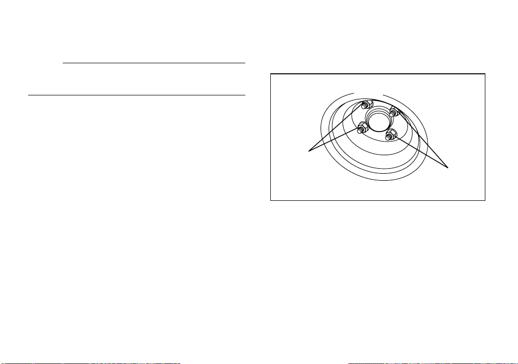
Wheel removal
To remove and install a wheel on your utility
vehicle:
1
1
1. Nut (× 4)
1. With the wheels blocked to prevent the
utility vehicle from moving, loosen the
wheel nuts.
2. Elevate the utility vehicle with a jack and
remove the wheel nuts.
3. Remove the wheel.
8-18
Page 73

Wheel installation
1. Install the wheel and the nuts.
NOTE:
_
●
Tapered nuts are used for both the front
and rear wheels. Install the nut with its tapered side towards the wheel.
●
The arrow mark on the tire must point
toward the rotating direction of the wheel.
_
1. Arrow mark
1. Tapered nut
2. Lower the vehicle so that the wheel is on
the ground.
3. Tighten the wheel nuts to the specified
torque.
Wheel nut torque:
Front: 80 Nm (8.0 m·kgf, 58 ft·lbf)
Rear: 80 Nm (8.0 m·kgf, 58 ft·lbf)
8-19
Page 74

Brake adjustment
The brakes on your utility vehicle are self-adjusting.
Before you operate the car, press down on
the brake pedal several times to make sure
the brakes are functioning properly.
WARNING
Consult your Yamaha dealer before using
your utility vehicle if you suspect brake
problems. Brake failure could result in a
serious accident.
Brake pedal free play adjustment
CAUTION:
Before adjusting brake pedal free play,
pump the brake pedal several times to
self-adjust the brakes.
To adjust the brake pedal free play:
1. Remove the service lid from the floor of
the utility vehicle.
Y-61a
8-20
Page 75

2. Check the brake pedal free play by
pressing against the pedal with two fingers (using light force) and measuring
the distance the pedal travels before resistance is felt.
Brake pedal free play:
20–25 mm (0.79–0.98 in)
3. If the free play distance needs adjusting,
loosen the locknut and turn the adjusting
nut in or out (in 180° increments only,
due to the cam shape of adjuster), until
the free play specification is met. Then
tighten the locknut to the specified
torque.
YXP700
a
a. Brake pedal free play
8
1
7
1
6
1
5
1
4
1
3
1
2
1
11
10
9
8
7
121
2
1. Locknut 2. Adjusting nut
8-21
Page 76

YXP1000
1. Locknut 2. Adjusting nut
Tightening torque:
17 N·m (1.7 m·kgf, 12 ft·lbf)
WARNING
Do not overtighten the adjusting nut or
locknut. The self adjusters may not operate properly, reducing braking performance.
Replacing a headlight bulb
If a headlight bulb burns out, replace it as follows.
1. Remove the headlight bulb holder by
turning it counterclockwise.
1. Headlight bulb holder
2. Remove the defective bulb by unhooking
the headlight bulb holder tabs.
8-22
Page 77

1. Headlight bulb holder tab (× 2)
3. Insert a new headlight bulb into the bulb
holder, and then hook the headlight bulb
holder tabs.
4. Install the headlight bulb holder by turning it clockwise.
Adjusting a headlight beam
CAUTION:
It is advisable to have a Yamaha dealer
make this adjustment.
To raise the beam, turn the adjusting screw in
direction a.
To lower the beam, turn the adjusting screw in
direction b.
1. Headlight beam adjusting screw
8-23
Page 78

Replacing a taillight bulb
If a taillight bulb burns out, have a Yamaha
dealer replace it.
8-24
Page 79

1-
CLEANING AND STORAGE
Perform the following preparations when storing your utility vehicle for extended periods of
time:
NOTE:
Turn main switch key to “OFF” position, remove key, and store key in a safe place.
Draining the fuel
1. Fill the fuel tank with fresh fuel and add
the specified amount of Yamaha Fuel
Stabilizer and Conditioner or equivalent
product. Operate the utility vehicle for at
least 5 minutes to distribute treated fuel
through the fuel system.
2. Drain the carburetor float chamber into a
clean container by loosening the drain
bolt; this will help prevent fuel deposits
from building up. Pour the drained fuel
into the fuel tank.
Specified amount:
1 oz of stabilizer for each gallon of fuel
(7.5 cc of stabilizer for each liter of fuel)
NOTE:
Use of fuel stabilizer and conditioner eliminates the need to drain the fuel system. Consult a Yamaha dealer if the fuel system needs
to be drained instead.
Engine preparation
1. With the key removed and the spark plug
lead disconnected, turn the clutch by
hand until compression is felt. This puts
the valves in the closed position.
2. Remove the spark plug, pour about one
tablespoon of SAE 10W30 or 20W40
motor oil in the spark plug hole and reinstall the spark plug. Ground the spark
plug wire and turn the engine over several times to coat the cylinder wall with oil.
3. Lubricate all control cables.
9-1
1
2
3
4
5
6
7
8
9
10
11
12
13
14
Page 80

Chassis preparation
1. Block up the frame to raise all wheels off
the ground.
2. Clean exterior of the utility vehicle and
apply a rust inhibitor.
3. Cover the utility vehicle with a breathable
cover and store it in a dry, well-ventilated
area.
Battery preparation
1. Remove the battery from the utility vehicle and store it in a cool, dry place that
stays between 0 °C (32 °F) and 30 °C
(90 °F).
2. Have the battery recharged every 60–90
days to keep it fully charged. The battery
must be kept fully charged to avoid damage.
NOTE:
Batteries like the one supplied with your vehicle normally do not require you to check the
water level inside the battery for the one year
warranty period provided by the manufacturer.
9-2
Page 81

1-
SPECIFICATIONS
1
Model YXP700/YXP1000
Dimensions:
Overall length 2492 mm (98.1 in) (YXP700)
3011 mm (118.5 in) (YXP1000)
Overall width 1232 mm (48.5 in) (YXP700)
1289 mm (50.7 in) (YXP1000)
Overall height (steering height) 1275 mm (50.2 in) (YXP700)
1353 mm (53.3 in) (YXP1000)
Height of floor 391 mm (15.4 in) (YXP700)
463 mm (18.2 in) (YXP1000)
Wheelbase 1637 mm (64.4 in) (YXP700)
1939 mm (76.3 in) (YXP1000)
Tread:
Front 940 mm (37.0 in) (YXP700)
1029 mm (40.5 in) (YXP1000)
Rear 980 mm (38.6 in) (YXP700)
1029 mm (40.5 in) (YXP1000)
Ground clearance 116 mm (4.6 in) (YXP700)
143 mm (5.6 in) (YXP1000)
10-1
2
3
4
5
6
7
8
9
10
11
12
13
14
Page 82

Model YXP700/YXP1000
Weight:
Dry weight (without battery) 339 kg (747 lb) (YXP700)
452 kg (996 lb) (YXP1000)
Performance:
Maximum speed 24 km/h (15 mph)
Minimum turning radius 3.0 m (118.1 in) (YXP700)
4.3 m (169.3 in) (YXP1000)
Seating capacity 2 persons
Engine:
Engine type Air-cooled 4-stroke, OHV
Cylinder arrangement Forward-inclined single cylinder
Displacement 357 cm
3
Bore x stroke 85 x 63 mm (3.30 x 2.48 in)
Compression ratio 8.0:1
Starting system Electric starter
Ignition system TCI Magneto
Spark plug type/manufacturer BPR2ES/NGK
Spark plug gap 0.7–0.8 mm (0.028–0.031 in)
Lubrication system Splash
10-2
Page 83

Model YXP700/YXP1000
Engine oil:
Type YAMALUBE 4 (10W30) or SAE 10W30
Recommended engine oil classification API Service SE type or higher
Quantity:
Oil change 0.9 L (0.79 Imp qt, 0.95 US qt)
Transmission:
Type V-belt automatic centrifugal
V-belt width and outer line length 31 x 1010 mm (1.22 x 39.76 in)
V-belt wear limit 27.9 mm (1.10 in)
Transmission oil:
Type SAE 90 gear oil
Quantity 0.42 L (0.37 Imp qt, 0.44 US qt)
Steering system:
Type Rack and pinion (YXP700)
Worm and pin (YXP1000)
10-3
Page 84

Model YXP700/YXP1000
Brakes:
Brake system Mechanical drum brake on rear wheels with self-
adjusters (YXP700)
Mechanical drum brake on front and rear wheels with
self-adjusters (YXP1000)
Type of brake Dual internal expanding shoe
Leading/trailing shoes (self-adjusting)
Brake pedal freeplay linkage adjustment 20–25 mm (0.79–0.98 in)
Parking brake:
Type Foot type; with automatic release
Wheel:
Tire size:
Front 20 x 10–8 / 4 PLY (YXP700)
22 x 11–10 / 6 PLY (YXP1000)
Rear 20 x 10–8 / 4 PLY (YXP700)
22 x 11–10 / 6 PLY (YXP1000)
Tire pressure:
2
Front 70–84 kPa (0.70–0.84 kgf/cm
, 10–12 psi)
Rear 70–84 kPa (0.70–0.84 kgf/cm2, 10–12 psi)
Battery: BCI group 24 (52 AH, 20 hr rate)
RC: minimum 75 min
CCA: minimum 400A
10-4
Page 85

Model YXP700/YXP1000
Bulb voltage, wattage × quantity:
Headlight 12 V, 30 W / 30 W × 2
Taillight Sealed beam × 2
Indicator light:
Engine oil level warning light 12 V, 3.4 W × 1
Specified fuses:
Main fuse 20 A
Headlight/signaling system fuse 10 A
Auxiliary DC jack fuse 10 A
10-5
Page 86

1-
MAINTENANCE RECORD
Copies of work orders and/or receipts for parts you purchase and install will be required to document maintenance done in accordance with the warranty. The chart below is printed only as a reminder to you that the maintenance work is required. It is not acceptable proof of maintenance
work.
MAINTENANCE
INTERVAL
month km (mi) hours
1 160 (100) 20
6 1,000 (600) 125
12 2,000 (1,200) 250
18 3,000 (1,800) 375
24 4,000 (2,400) 500
30 5,000 (3,000) 625
36 6,000 (3,600) 750
42 7,000 (4,200) 875
48 8,000 (4,800) 1,000
54 9,000 (5,400) 1,125
60 10,000 (6,000) 1,250
DATE OF
SERVICE
MILEAGE
SERVICING DEALER
NAME AND ADDRESS
11-1
REMARKS
Page 87

YAMAHA MOTOR CORPORATION, U.S.A.
Yamaha Motor Corporation, U.S.A. hereby warrants
that new Yamaha Side × Side vehicles purchased
from an authorized Yamaha Side × Side Vehicle
dealer in the continental United States will be free
from defects in material and workmanship for the
period of time stated herein, subject to certain stated
limitations.
THE PERIOD OF WARRANTY for YXR OR YXP
Yamaha Side × Side vehicles shall be six (6) months
from the date of purchase, with no mileage limitation.
MODELS EXCLUDED FROM WARRANTY include
those used for non-Yamaha-authorized renting,
leasing, or other commercial purposes.
DURING THE PERIOD OF WARRANTY any
authorized Yamaha Side × Side Vehicle dealer will
free of charge, repair or replace, at Yamaha’s option,
any part adjudged defective by Yamaha due to faulty
workmanship or material from the factory. Parts used
in warranty repairs will be warranted for the balance
of the product’s warranty period. All parts replaced
under warranty become property of Yamaha Motor
Corporation, U.S.A.
VEHICLE LIMITED WARRANTY
GENERAL EXCLUSIONS from this warranty shall
include any failures caused by:
a.
Competition or racing use.
b.
Installation of parts or accessories that are not
qualitatively equivalent to genuine Yamaha parts.
c.
Abnormal strain, neglect, or abuse.
d.
Lack of proper maintenance.
e.
Accident or collision damage.
f.
Modification to original parts.
g.
Damage due to improper transportation.
SPECIFIC EXCLUSIONS from this warranty shall
include parts replaced due to normal wear or routine
maintenance; such as spark plugs, oil, oil filter, air
filter, and brake shoes.
THE CUSTOMER’S RESPONSIBILITY under this
warranty shall be to:
Operate and maintain the Side-by-Side vehicle as
1.
specified in the appropriate Owner’s Manual, and
Give notice to an authorized Yamaha Side × Side
2.
Vehicle dealer of any and all apparent defects
within ten (10) days after discovery, and make the
machine available at that time for inspection and
repairs at such dealer’s place of business.
WARRANTY TRANSFER: To transfer the warranty
from the original purchaser to any subsequent
purchaser(s), it is imperative that the Side-by-Side
vehicle be inspected and registered for warranty by
an authorized Yamaha Side-by-Side Vehicle dealer. In
order for this warranty to remain in effect, this
inspection and registration must take place within ten
(10) days after transfer of ownership to the
subsequent purchaser. A reasonable dealer imposed
fee may be charged for this inspection.
YAMAHA MOTOR CORPORATION, U.S.A. MAKES
NO OTHER WARRANTY OF ANY KIND, EXPRESSED
OR IMPLIED. ALL IMPLIED WARRANTIES OF
MERCHANTABILITY AND FITNESS FOR A
PARTICULAR PURPOSE WHICH EXCEED THE
OBLIGATIONS AND TIME LIMITS STATED IN THIS
WARRANTY ARE HEREBY DISCLAIMED BY
YAMAHA MOTOR CORPORATION, U.S.A. AND
EXCLUDED FROM THIS WARRANTY.
SOME STATES DO NOT ALLOW LIMITATIONS ON
HOW LONG AN IMPLIED WARRANTY LASTS, SO
THE ABOVE LIMITATION MAY NOT APPLY TO YOU.
ALSO EXCLUDED FROM THIS WARRANTY ARE
ANY INCIDENTAL OR CONSEQUENTIAL DAMAGES
INCLUDING LOSS OF USE. SOME STATES DO
NOT ALLOW THE EXCLUSION OR LIMITATION OF
INCIDENTAL OR CONSEQUENTIAL DAMAGES, SO
THE ABOVE EXCLUSION MAY NOT APPLY TO YOU.
THIS WARRANTY GIVES YOU SPECIFIC LEGAL
RIGHTS, AND YOU MAY ALSO HAVE OTHER
RIGHTS WHICH VARY FROM STATE TO STATE.
1
2
3
4
5
6
7
8
9
10
11
12
13
14
12-1
Page 88

YAMAHA EXTENDED SERVICE (Y.E.S.)
13-1
Page 89

1
2
3
4
5
6
7
8
9
10
11
12
13
14
13-2
Page 90

Page 91

Page 92

PRINTED ON RECYCLED PAPER
YAMAHA MOTOR CO., LTD.
PRINTED IN USA
2004.01-0.3×1 CR
(E)
 Loading...