

Page 1
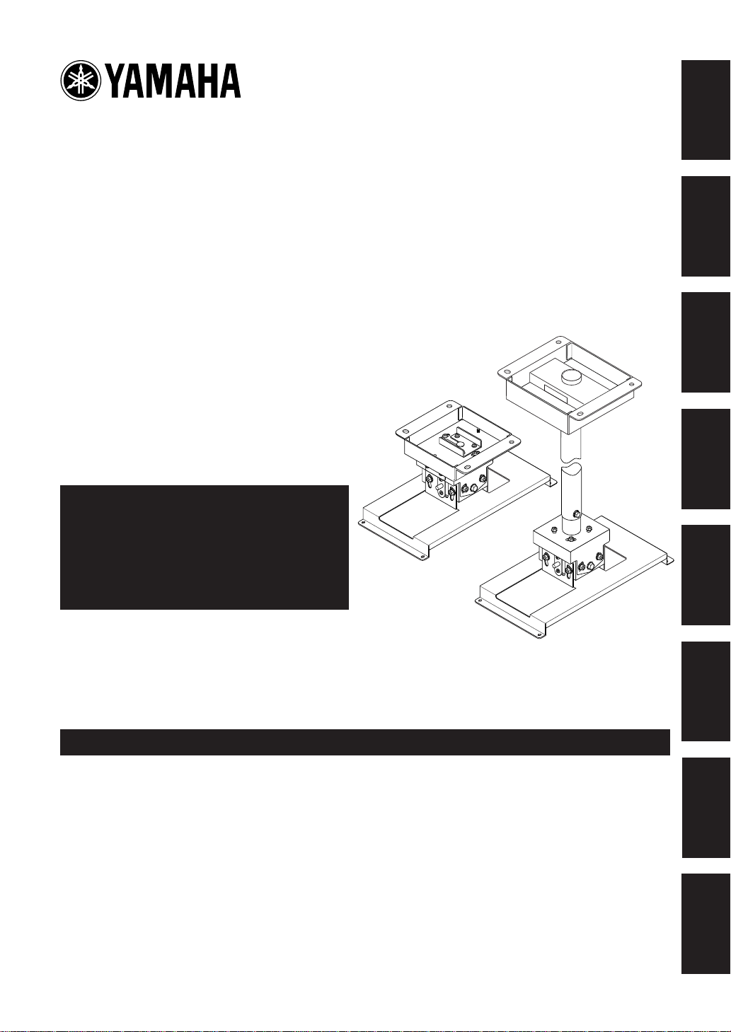
Ceiling Mount Bracket
PMT-L21 (for Low Ceilings)
PMT-H25 (for High Ceilings)
English
Français
Installation Manual
Be sure to read this manual thoroughly
before using this bracket. After you have
read this manual, retain it for future
reference.
When installing the projector using this
bracket, all installation work must be
performed by a qualified contractor or
dealer personnel. The customer must
never attempt to perform this installation
work.
Deutsch
Svenska
Italiano
(PMT-L21)
(PMT-H25)
Español
Contents
SAFETY INSTRUCTIONS .............................................................................................................2
PACKING LIST.............................................................................................................................. 4
NAMES OF PARTS ....................................................................................................................... 5
DIMENSIONS OF PARTS .............................................................................................................7
SCREEN SIZE AND SETTING-UP DISTANCE ............................................................................ 8
INSTALLATION EXAMPLES....................................................................................................... 10
INST ALLING THE PROJECT OR ................................................................................................. 11
ADJUSTING THE PROJECTION ANGLE................................................................................... 14
SPECIFICATIONS ....................................................................................................................... 16
Nederlands
日本語
Page 2

SAFETY INSTRUCTIONS
1. Always follow the instructions set forth in this manual when installing the projector
using this bracket.
Improper or inadequate installation could cause the projector to fall and injure someone.
2. The installation must be secure enough to bear the weight of the projector, the ceiling
bracket, and other hardware indefinitely, and must also be secure enough to withstand
vibration.
Inadequate installation could cause the projector to fall and injure someone.
3. To ensure safety, all bolts and screws must be tightened securely.
Loose bolts or screws could cause the projector to fall and injure someone.
4. Use only the parts provided with the bracket, and any other parts (commrecially
available) that are specified in this manual.
Using other parts could cause the projector to fall and injure someone.
5. Do not modify the bracket or the parts provided with the bracket.
Modifying the bracket or the other parts could cause the projector to fall and injure someone.
6. Do not use damaged parts.
Using damaged parts could cause the projector to fall and injure someone.
If any parts become damaged, contact your dealer.
PMT-L21/PMT-H25
7. Make sure to leave enough open space around the unit to allow heat generated by the
projector to dissipate.
Failure to provide adequate space around the unit could cause the projector to overheat internally, causing a
fire.
8. Before replacing the lamp cartridge, always remove the projector (with the mounting
adapter attached) from the ceiling bracket.
Attempting to replace the lamp cartridge while the projector is attached to the ceiling bracket could cause
the projector or the ceiling bracket to fall and injure someone.
E-2
Page 3

9. Never hang from the projector or the ceiling bracket.
Hanging from the projector or the ceiling bracket could cause the projector or the ceiling bracket to fall and
injure someone.
10. Do not install the projector in a location near an air conditioning vent or in a location
subject to vibration.
Such conditions could have an adverse effect on the projector, and could even cause a fire or electric shock.
11. Do not install the projector in a location that is subject to high levels of dust or
humidity.
Dust accumulating inside the projector could cause a short circuit that in turn could cause a fire or electric
shock.
12. Do not install the projector in a location that is exposed to direct sunlight or in a
location that is subject to extreme fluctuations in temperature (such as near an air
conditioner).
Such conditions can cause the projector housing to warp or to become discolored.
13. Do not wipe the exterior of the ceiling bracket with benzene, paint thinner or cleaning
compounds.
English
Français
Deutsch
Svenska
Doing so could damage the finish.
14. Special techniques and experience are essential when installing the projector using
this bracket. Request that your dealer arrange to have the equipment installed. The
customer should never attempt to suspend the projector from the ceiling.
Improper installation could cause the ceiling bracket or the projector to fall and injure someone.
15. Once the projector is installed, safety checks should be conducted on a regular basis.
If the projector is used over an extended period of time, screws can become loose and the installation can
become weaker due to the passage of time, vibration, etc.
Italiano
Español
Nederlands
E-3
Page 4

PACKING LIST
Check that all of the following parts are included.
PMT-L21
Ceiling bracket x 1
PMT-H25
Ceiling bracket x 1
Adjustment pole locking screws (M5) x 4
Common parts (The following parts are provided with each bracket.)
Projector mounting adapter x 1
Safety brackets x 2
Safety wires x 2
Projector mounting screws
(M4, pan head) x 4
Vertical angle adjustment screws
(M6, hexagonal head) x 4
Safety bracket mounting screws
(M4, pan head) x 4
Safety wire mounting screws
(M4, pan head) x 4
Installation Manual x 1
E-4
Page 5

NAMES OF PARTS
PMT-L21
Horizontal angle adjustment
screws
English
Français
Ceiling bracket
Mounting guide pin
Vertical angle adjustment screws
(There are also screws on the
opposite side.)
Deutsch
Svenska
Italiano
Tilt angle adjustment screws
(There are also screws on the
opposite side.)
Español
Projector mounting adapter
E-5
Nederlands
Page 6

PMT-H25
Ceiling bracket
Height locking screw
Height adjustment pole
Mounting guide pin
Vertical angle adjustment screws
(There are also screws on the
opposite side.)
Horizontal angle adjustment screw
(four in total)
Tilt angle adjustment screws
(There are also screws on the
opposite side.)
Projector mounting adapter
E-6
Page 7

DIMENSIONS OF PARTS
English
Projector mounting adapter
184 mm (7-1/4 inch) 178.5 mm (7 inch)
170.5 mm (6-3/4 inch) 170.5 mm (6-3/4 inch)
8 mm
(5/16 inch)
175 mm (6-7/8 inch)
147.3 mm (5-3/4 inch)
178 mm (7-1/16 inch)
170.5 mm (6-3/4 inch)
PMT-L21
[Front View]
81 mm
137 mm
(5-3/8 inch)
(3-3/16 inch)
8 mm
(5/16 inch)
159 mm (6-1/4 inch)
192 mm
(7-9/16 inch)
PMT-H25
[Front View]
777 to 1347 mm
832 to 1402 mm
(32-3/4 to 55-3/16 inch)
(30-9/16 to 53 inch)
Ø8.8 mm
(Ø3/16 inch)
(fully penetrating holes)
30 mm
(1-3/16 inch)
Français
Deutsch
887 to 1457 mm
(34-15/16 to 57-3/8 inch)
Svenska
Italiano
[T op View]
Ø10 x 13 mm
196 mm
170 mm
(7-3/4 inch)
(6-11/16 inch)
Ø9 x 13 mm
10° 10°
with the LPX-500 installed
(Ø3/8 x 1/2 inch)
(elliptical hole)
140 mm
(5-1/2 inch)
120 mm
(4-3/4 inch)
156 mm
(6-1/8 inch)
(Ø3/8 x 1/2 inch)
(elliptical hole)
Ø10 mm
(Ø3/8 inch)
(hole)
Ø9 mm
(Ø3/8 inch)
10˚
10˚
(hole)
[T op View]
Ø10 x 13 mm
200 mm
226 mm
(8-7/8 inch)
Ø9 x 13 mm
with the LPX-500 installed
(Ø3/8 x 1/2 inch)
(elliptical hole)
(7-7/8 inch)
140 mm
(5-1/2 inch)
175 mm
(6-7/8 inch)
(Ø3/8 x 1/2 inch)
(elliptical hole)
Ø10 mm
(Ø3/8 inch)
(hole)
Ø9 mm
(Ø3/8 inch)
Español
Nederlands
(hole)
E-7
Page 8

SCREEN SIZE AND SETTING-UP DISTANCE
The distance between the projector and the screen (16:9) determines the actual image size.
Recommended distance: 0.9 to 13.0 m (2.9 to 12.6 feet)
While referring to the table below, position the projector so that the image size is smaller than the screen
size.
Screen size (cm [feet])
30" (66 x 37 [2.1 x 1.2]) 0.9 to 1.2 [2.9 to 3.9] 5.0 to 5.1 [0.16 to 0.17]
40" (89 x 50 [2.8 x 1.6]) 1.2 to 1.6 [3.9 to 5.2] 6.7 to 6.8 [0.22 to 0.22]
60" (130 x 75 [4.2 x 2.4]) 1.8 to 2.5 [5.9 to 8.2] 10.2 [0.33]
80" (180 x 100 [5.7 x 3.2]) 2.5 to 3.4 [8.2 to 11.1] 13.6 to 13.7 [0.45 to 0.45]
100" (220 x 120 [7.2 x 4.1]) 3.1 to 4.3 [10.1 to 14.1] 17.0 to 17.1 [0.56 to 0.56]
200" (440 x 250 [14.4 x 8.2]) 6.3 to 8.6 [20.6 to 28.2] 34.0 to 34.3 [1.12 to 1.13]
300" (660 x 370 [21.6 x 12.1]) 9.5 to 13.0 [31.1 to 42.6] 51.0 to 51.4 [1.67 to 1.69]
* Distance and dimensions should be used as a guide for installation. The actual distance will vary depending on
projection conditions.
Approximate projection size* (m [feet])
Distance in Fig. A below (cm [feet])
Distance from center of
ceiling bracket to front
edge of projector:
Approx. 12 cm
Distance from center of
lens to top edge of screen
(cm)
0.9 to 1.2
1.2 to 1.6
5.0 to
6.7 to
5.1
6.8
30"
(66 × 37)
1.8 to 2.5
2.5 to 3.4
40"
(89 × 50)
3.1 to 4.3
6.3 to 8.6
9.5 to 13.0
Approximate projection size (m)
10.2 13.6 to
60"
(130 × 75)
(180 × 100)
13.7
80"
(220 × 120)
17.0 to
17.1
100"
34.0 to
34.3
200"
(440 × 250)
Screen size (cm)
51.0 to
51.4
Distance from ceiling
surface to center of
lens:
PMT-L21:
Approx. 19 cm
PMT-H25:
89 to 146 cm
300"
(660 × 370)
Notes
• The projection distance is the horizontal distance from the surface of the projector lens to the surface of the screen.
In the case of the LPX-500, the surface of the lens is recessed by approximately 3 cm from its exterior.
• Although the vertical angle of the ceiling bracket can be adjusted in a range of ±15°, a large angle adjustment may
distort the projected image. We recommend you to adjust both the angle of the ceiling bracket and the angle of the
screen.
• The lens of the LPX-500 allows a zoom ration of up to about 1.35. The image size at the maximum zoom setting is
about 1.35 times bigger than the image size at the minimum zoom setting.
• The image size will be reduced when keystone correction is carried out.
E-8
 Loading...