

Page 1

CEILING MOUNT BRACKET
PMT-L71 (for Low Ceilings)
PMT-H75 (for High Ceilings)
Installation Manual
Be sure to read this manual thoroughly before
using this bracket. After you have read this
manual, retain it for future reference.
When installing the projector using this
bracket, all installation work must be
performed by a qualified contractor or
dealer personnel. The customer must
never attempt to perform this installation
work.
(PMT-L71)
(PMT-H75)
Contents
SAFETY INSTRUCTIONS .............................................................................................................2
PACKING LIST .............................................................................................................................. 4
NAMES OF PARTS ....................................................................................................................... 5
DIMENSIONS OF PARTS .............................................................................................................7
SCREEN SIZE AND SETTING-UP DISTANCE ............................................................................ 8
INSTALLATION EXAMPLES....................................................................................................... 11
INSTALLING THE PROJECTOR ................................................................................................. 13
ADJUSTING THE PROJECTION ANGLE................................................................................... 16
SPECIFICATIONS ....................................................................................................................... 18
Page 2

SAFETY INSTRUCTIONS
1. Always follow the instructions set forth in this manual when installing the projector
using this bracket.
Improper or inadequate installation could cause the projector to fall and injure someone.
2. The installation must be secure enough to bear the weight of the projector, the ceiling
bracket, and other hardware indefinitely, and must also be secure enough to withstand
vibration.
Inadequate installation could cause the projector to fall and injure someone.
3. To ensure safety, all bolts and screws must be tightened securely.
Loose bolts or screws could cause the projector to fall and injure someone.
4. Use only the parts provided with the bracket, and any other parts (commercially
available) that are specified in this manual.
Using other parts could cause the projector to fall and injure someone.
5. Do not modify the bracket or the parts provided with the bracket.
Modifying the bracket or the other parts could cause the projector to fall and injure someone.
6. Do not use damaged parts.
Using damaged parts could cause the projector to fall and injure someone.
If any parts become damaged, contact your dealer.
7. Make sure to leave enough open space around the unit to allow heat generated by the
projector to dissipate.
Failure to provide adequate space around the unit could cause the projector to overheat internally, causing a
fire.
8. Before replacing the lamp cartridge, always remove the projector (with the mounting
adapter attached) from the ceiling bracket.
Attempting to replace the lamp cartridge while the projector is attached to the ceiling bracket could cause
the projector or the ceiling bracket to fall and injure someone.
E-2
Page 3

9. Never hang from the projector or the ceiling bracket.
Hanging from the projector or the ceiling bracket could cause the projector or the ceiling bracket to fall and
injure someone.
10. Do not install the projector in a location near an air conditioning vent or in a location
subject to vibration.
Such conditions could have an adverse effect on the projector, and could even cause a fire or electric shock.
11. Do not install the projector in a location that is subject to high levels of dust or
humidity.
Dust accumulating inside the projector could cause a short circuit that in turn could cause a fire or electric
shock.
12. Do not install the projector in a location that is exposed to direct sunlight or in a
location that is subject to extreme fluctuations in temperature (such as near an air
conditioner).
Such conditions can cause the projector housing to warp or to become discolored.
13. Do not wipe the exterior of the ceiling bracket with benzene, paint thinner or cleaning
compounds.
Doing so could damage the finish.
14. Special techniques and experience are essential when installing the projector using
this bracket. Request that your dealer arrange to have the equipment installed. The
customer should never attempt to suspend the projector from the ceiling.
Improper installation could cause the ceiling bracket or the projector to fall and injure someone.
15. Once the projector is installed, safety checks should be conducted on a regular basis.
If the projector is used over an extended period of time, screws can become loose and the installation can
become weaker due to the passage of time, vibration, etc.
E-3
Page 4

PACKING LIST
Check that all of the following parts are included.
Common parts (The following parts are provided with each bracket.)
Projector mounting adapter x 1
Projector mounting screws x 4
Safety wire mounting screws x 4
(M6, pan head)
Safety brackets x 2
Safety wires x 2
PMT-L71
Ceiling bracket x 1
Vertical angle adjustment screws
(M6, hexagonal head) x 4
Safety bracket mounting screws
(M4, pan head) x 4
Installation Manual x 1
PMT-H75
Ceiling bracket x 1
Bracket safety wire (500 mm) x 1
E-4
Bracket safety wire (700 mm) x 1
Cable covers
inner x 2 outer x 2
Page 5

NAMES OF PARTS
PMT-L71
Ceiling bracket
Horizontal angle
adjustment screws
Tilt angle adjustment screws
(There are also screws on the
opposite side.)
[Bottom view]
[Bottom view]
Projector mounting adapter
Mounting guide pin
Vertical angle adjustment screws
(There are also screws on the
opposite side.)
Projection
direction
E-5
Page 6

PMT-H75
Ceiling bracket
Height adjustment pole
[Front View]
[Rear View]
Outer cable covers
Height adjustment pole
locking screws
Inner cable covers
Horizontal angle
adjustment screw
(four in total)
Vertical angle adjustment screws
(There are also screws on the
opposite side.)
E-6
Tilt angle adjustment screws
(There are also screws on the
opposite side.)
Projector mounting adapter
Page 7
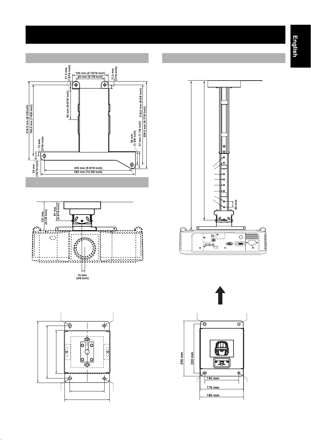
DIMENSIONS OF PARTS
Projector mounting adapter PMT-H75
[Rear View]
PMT-L71
461 to 761 mm
(18-1/8 to 29-15/16 inch)
511 to 811 mm
(20-1/8 to 31-15/16 inch)
[Front View]
[Top View]
Ø10 x 13 mm
196 mm (7-3/4 inch)
170 mm (6-11/16 inch)
Ø9 x 13 mm
(Ø3/8 x 1/2 inch)
(elliptical hole)
140 mm (5-1/2 inch)
120 mm(4-3/4 inch)
156 mm(6-1/8 inch)
(Ø3/8 x 1/2 inch)
(elliptical hole)
Ø10 mm
(Ø3/8 inch)
Ø9 mm
(Ø3/8 inch)
(hole)
(hole)
[Top View]
(9-11/16 inch)
Ø10 x 13 mm
(Ø3/8 x 1/2 inch)
(elliptical hole)
(8-5/8 inch)
Ø9 x 13 mm
(Ø3/8 x 1/2 inch)
(elliptical hole)
M6 size screw holes
Projection
direction
(5-1/2 inch)
(6-15/16 inch)
(7-1/16 inch)
Ø10 mm
(Ø3/8 inch)
Ø9 mm
(Ø3/8 inch)
(hole)
(hole)
E-7
Page 8
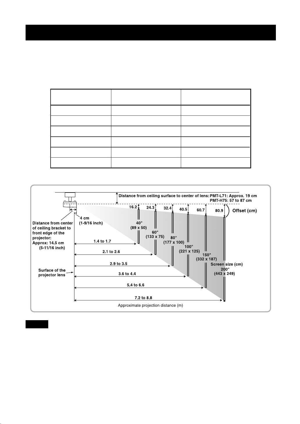
SCREEN SIZE AND SETTING-UP DISTANCE
The distance between the projector and the screen (16:9) determines the actual image size.The actual
distance will vary depending on projection conditions. For details on the screen size and setting-up
distance, refer to the owner’s manual of the projector.
While referring to the table below, position the projector so that the image size is smaller than the screen size.
Screen size (cm)
40'' (89 x 50)
60'' (133 x 75)
80'' (177 x 100)
100'' (221 x 125)
150'' (332 x 187)
200'' (443 x 249)
Example: Installation of the DPX-530
Projection distance (m [inch])
with DPX-530 installed
1.4 to 1.7 [55 ~ 67]
2.1 to 2.6 [84 ~ 102]
2.9 to 3.5 [113 ~ 137]
3.6 to 4.4 [142 ~ 171]
5.4 to 6.6 [213 ~ 258]
7.2 to 8.8 [285 ~ 345]
Projection distance (m [inch])
with DPX-830 installed
1.4 to 1.7 [56 ~ 68]
2.2 to 2.6 [85 ~ 103]
2.9 to 3.5 [114 ~ 139]
3.6 to 4.4 [143 ~ 174]
5.5 to 6.6 [216 ~ 262]
7.3 to 8.9 [289 ~ 349]
Notes
• The projection distance is the horizontal distance from the surface of the projector lens to the surface of the screen.
In the case of the DPX-530 or DPX-830, the surface of the lens is recessed by approximately 4 cm from its exterior.
• Although the vertical angle of the ceiling bracket can be adjusted in a range of ±15°, a large angle adjustment may
distort the projected image. We recommend you to adjust both the angle of the ceiling bracket and the angle of the
screen.
• The lens of the DPX-530 or DPX-830 allows a zoom ratio of up to about 1.2. The image size at the maximum zoom
setting is about 1.2 times bigger than the image size at the minimum zoom setting.
• The image size will be reduced when keystone correction is carried out.
E-8
Page 9
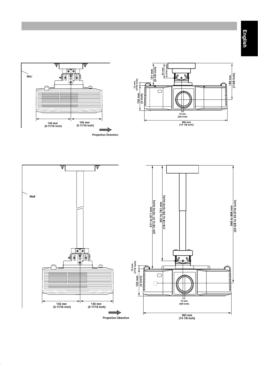
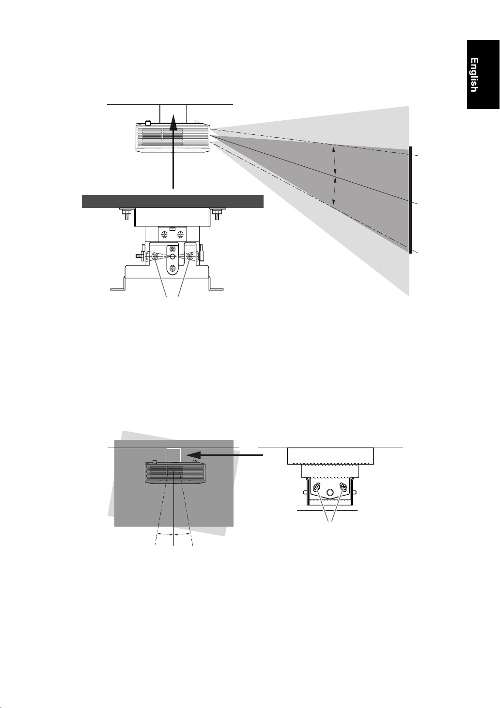
Placement of the ceiling mount bracket
Be sure to align the horizontal center of your screen with the projector’s lens, not the center of the
projector.
PMT-L71 Side View
PMT-H75 Side View
PMT-L71 Front View
PMT-H75 Front View
E-9
Page 10

PMT-H75 height adjustment
The height adjustment pole for the PMT-H75 has screw holes spaced 3 cm apart that can be used to adjust
the height. When the bracket is shipped from the factory, the pole is set at the shortest height.
Follow the procedure described below to adjust the pole to the appropriate height. For details on the
appropriate height, refer to “SCREEN SIZE AND SETTING-UP DISTANCE” on page 8.
[Height Adjustment Procedure]
1. Remove the adjustment pole locking screws (M6, pan head).
Removing the adjustment pole locking screws will unlock the inner height adjustment pole from the outer pole.
Caution
• Always hold the height adjustment pole while performing this work.
2. Determine the correct position in accordance with the height of the screen.
3. Insert both adjustment pole locking screws and tighten securely.
4. Insert the projector cables into the shaft of the adjustment pole.
5. Attach the cable covers to the height adjustment pole, over the cables.
The gap between the inner cable cover hooks is wider than the gap between the outer cable cover hooks. Be sure to
use the correct one when attaching them to the height adjustment pole.
Caution
• After adjusting the height, make sure that the adjustment pole locking screws are all tightened securely.
• Do not remove the stopper screws; otherwise, the inner height adjustment pole will fall and may cause injury.
[Rear View]
Stopper screw
(one more on the
other side)
1
3
2
5
4
5
E-10
Page 11

INSTALLATION EXAMPLES
When installing to a wooden ceiling
1. Drill matching holes through the reinforcing
plate and the ceiling in the proper locations
and then pass bolts through the holes.
2. Tighten the bolts to secure the reinforcing
plate to a ceiling beam.
Caution
• Make sure that the reinforcing plate is strong
enough to bear the weight of the projector and the
ceiling bracket.
• Use M8 bolts (commercially available).
When installing to a concrete ceiling
Reinforcing plate
Bolt (M8)
(Use the reinforcing plate, bolts, nuts and washers
commercially available.)
Washer
Nut and
washer
Ceiling
beam
1. Install anchor nuts in the ceiling.
2. Screw the bolts into the anchor nuts.
Caution
• Make sure that the anchor nuts are strong enough
to bear the weight of the projector and the ceiling
bracket.
• Use M8 bolts (commercially available).
Anchor nut
Ceiling
Nut and
washer
Bolt (M8)
(Use the anchor nuts, bolts, nuts and washers
commercially available.)
E-11
Page 12

Attaching the bracket safety wire
Be sure to attach the bracket safety wire to prevent the bracket and projector from falling off from the
ceiling.
PMT-L71
1. Place the bracket safety wire through the openings
on the sides of the bracket.
2. Fix both ends of the bracket safety wire to the
ceiling.
Caution
• Be sure the ceiling and the attachments are strong enough
to support the entire weight.
To the ceiling
PMT-H75
1. Wind the bracket wire around the height adjustment pole as shown in the illustration.
2. Fix both ends of the bracket safety wire to the ceiling.
Caution
• Be sure the ceiling and the attachments are strong enough
to support the entire weight.
To the ceiling To the ceiling
To the ceiling
E-12
Page 13

INSTALLING THE PROJECTOR
1 Attach the projector mounting adapter onto the projector.
Align the holes in the mounting adapter with the holes in the bottom of the projector, and then use the four
projector mounting screws (M6, pan head) provided to securely attach the mounting adapter to the
projector.
Projector mounting screws
Projector mounting adapter
(M6, pan head)
Bottom of the projector
Caution
• Do not tighten the projector mounting screws excessively. Excessive tightening could damage the mount and cause
the projector to fall.
2 Attach the safety wires.
Use the four safety wire mounting screws (M6, pan head) provided to attach the safety wires to the
projector mounting adapter, as shown below.
Projector mounting adapter
Safety wire
Safety wire mounting screws
(M6, pan head)
E-13
Page 14
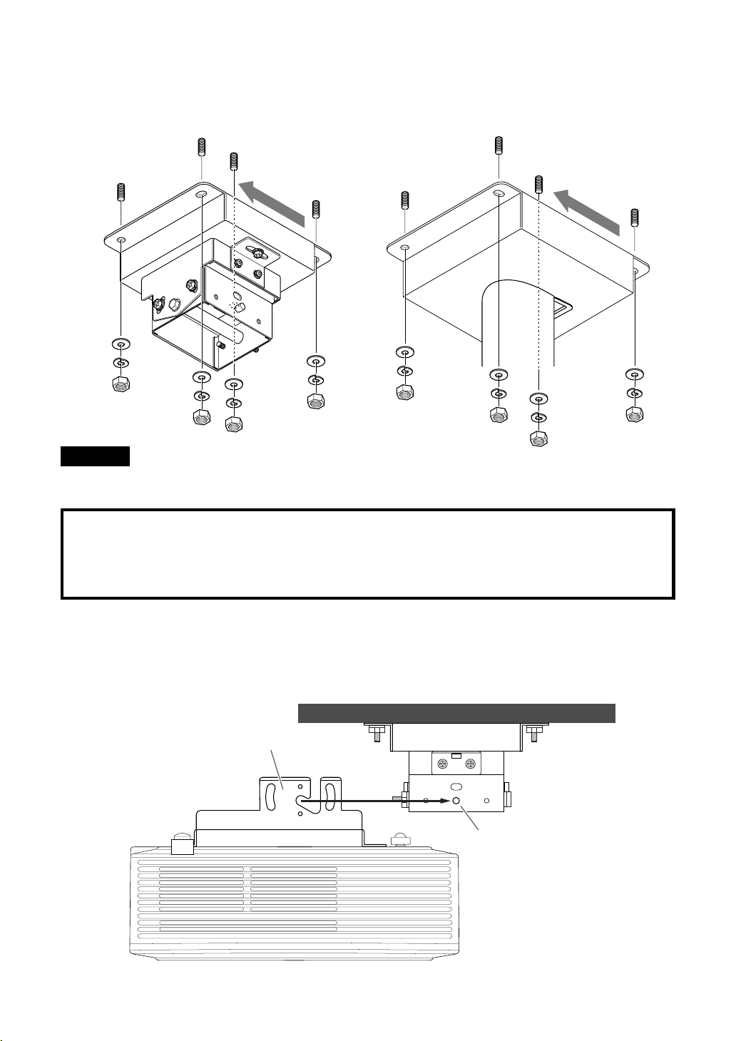
3 Install the ceiling bracket on the ceiling.
First hand-tighten the four nuts, determine the position, and then tighten the nuts securely.
(PMT-L71) (PMT-H75)
Projection
direction
Projection
direction
Caution
• Use M8 bolts (commercially available) to install the ceiling bracket. Using any bolts other than M8 bolts could
cause the projector to fall.
Note to Dealers and Installers
For the customer’s safety, make sure that the location where the projector is to be installed is strong
enough to bear the weight of the projector, the ceiling bracket, and the other hardware before
installing the ceiling bracket.
4 Hang the projector from the ceiling bracket.
Slide the mounting guide pin all of the way into the notch on the projector mounting adapter. This pin is
only meant to support the projector temporarily, and does not hold the projector securely. Be careful that
the projector does not fall.
Projector mounting adapter
(PMT-L71)
Mounting guide pin
E-14
Page 15

5 Attach the safety brackets.
Align the safety brackets so that the mounting guide pin fits into the hole, and then use the four safety
bracket mounting screws (M4, pan head) to secure the brackets. (Use two screws on the left side and two
screws on the right.)
(PMT-L71)
Safety bracket mounting screw
(M4, pan head)
Safety bracket
Projection
direction
6 Temporarily secure the projector mounting adapter.
Use the four vertical angle adjustment screws (M6, hexagonal head) provided to temporarily secure the
projector mounting adapter. (Use two screws on the left side and two screws on the right.)
(PMT-L71)
Vertical angle adjustment screws
(Hand-tighten the other side also.)
E-15
Page 16

ADJUSTING THE PROJECTION ANGLE
Before adjustment
• Turn the projector on and project an image, following the instructions on the owner’s manual of the
projector.
• Set the appropriate projection method on “Installation” item in “Set up” menu. For the detail about the
setting, refer to the owner’s manual of the projector.
• First, select a projection size using the zoom feature, and then adjust the angle.
1 Adjust the horizontal angle.
Adjust the projector so that the projected image is centered horizontally on the screen, and then tighten the
horizontal angle adjustment screws (2 on the PMT-L71, 4 on the PMT-H75).
Left
Maximum angle of
adjustment: ±10˚
10˚
Right
10˚
(PMT-L71)
Horizontal angle adjustment screws
E-16
(PMT-H75)
Page 17
2 Adjust the vertical angle.
Adjust the projector so that the projected image is centered vertically on the screen, and then tighten the
four vertical angle adjustment screws.
Top
15˚
15˚
Maximum angle of
adjustment: ±15˚
(PMT-L71)
Bottom
(There are also screws located on the opposite side.)
Vertical angle adjustment screws
3 Adjust the tilt angle.
Adjust the projector so that the projected image is not tilted at all compared to the screen, and then tighten
the four tilt angle adjustment screws.
(PMT-L71)
10˚ 10˚
Maximum angle of adjustment: ±10˚
(There are also screws located on the opposite side.)
If the projector still needs further adjustment, start over from step 1.
Tilt angle adjustment screws
After adjustment is completed, make sure that the projector is secured in place.
E-17
Page 18

SPECIFICATIONS
Product Name Ceiling Mount Bracket
Model No. PMT-L71 PMT-H75
Height
Adjustment
range
Dimensions of ceiling bracket
(W × D × H)
Dimensions of adapter
(W × D × H)
Weight 2.5 kg (5 lbs 8 oz) 4.1 kg (9 lbs)
• Specifications are subject to change without notice.
Ve rtical angle ±15˚ ±15˚
Horizontal angle ±10˚ ±10˚
Tilt angle ±10˚ ±10˚
131 mm (5-1/8 inch)
(fixed)
156 × 196 × 94 mm
(6-1/8 × 7-3/4 × 3-11/16 inch)
263 × 239.5 × 72 mm (10-5/16 × 9-7/16 × 2-13/16 inch)
511 to 811 mm (20-1/8 to
31-15/16 inch)
(variable in 30 mm (1-3/16 inch) steps)
180 × 246 × 511 to 811 mm
(7-1/16 × 8-7/8 × 20-1/8 to 31-15/16 inch)
(Height is variable in 30-mm
(1-3/16 inch) steps)
E-18
Page 19

YAMAHA ELECTRONICS CORPORATION, USA
YAMAHA CANADA MUSIC LTD.
YAMAHA ELECTRONIK EUROPA G.m.b.H.
YAMAHA ELECTRONIQUE FRANCE S.A.
YAMAHA ELECTRONICS (UK) LTD.
YAMAHA SCANDINAVIA A.B.
YAMAHA MUSIC AUSTRALIA PTY, LTD.
135 MILNER AVE., SCARBOROUGH, ONTARIO M1S 3R1, CANADA
SIEMENSSTR. 22-34, 25462 RELLINGEN BEI HAMBURG, GERMANY
RUE AMBROISE CROIZAT BP70 CROISSY-BEAUBOURG 77312 MARNE-LA-VALLEE CEDEX02, FRANCE
YAMAHA HOUSE, 200 RICKMANSWORTH ROAD WATFORD, HERTS WD18 7GQ, ENGLAND
J A WETTERGRENS GATA 1, BOX 30053, 400 43 VÄSTRA FRÖLUNDA, SWEDEN
17-33 MARKET ST., SOUTH MELBOURNE, 3205 VIC., AUSTRALIA
2006
6660 ORANGETHORPE AVE., BUENA PARK, CALIF. 90620, U.S.A.
Printed in Japan PMT-L71/H75-2
 Loading...