

Page 1
PM5D/PM5D-RH V2
DSP5D
Owner’s Manual
Owner’s Manual
EN
Page 2
FCC INFORMATION (U.S.A.)
1. IMPORTANT NOTICE: DO NOT MODIFY THIS UNIT!
This product, when installed as indicated in the instructions contained in this manual, meets FCC requirements. Modifications not
expressly approved by Yamaha may void your authority, granted by
the FCC, to use the product.
2. IMPORTANT:
or another product use only high quality shielded cables. Cable/s
supplied with this product MUST be used. Follow all installation
instructions. Failure to follow instructions could void your FCC
authorization to use this product in the USA.
3. NOTE:
requirements listed in FCC Regulations, Part 15 for Class “B” digital
devices. Compliance with these requirements provides a reasonable level of assurance that your use of this product in a residential
environment will not result in harmful interference with other electronic devices. This equipment generates/uses radio frequencies
and, if not installed and used according to the instructions found in
the users manual, may cause interference harmful to the operation
of other electronic devices. Compliance with FCC regulations does
* This applies only to products distributed by YAMAHA CORPORATION OF AMERICA. (class B)
When connecting this product to accessories and/
This product has been tested and found to comply with the
not guarantee that interference will not occur in all installations. If
this product is found to be the source of interference, which can be
determined by turning the unit “OFF” and “ON”, please try to eliminate the problem by using one of the following measures:
Relocate either this product or the device that is being affected by
the interference.
Utilize power outlets that are on different branch (circuit breaker or
fuse) circuits or install AC line filter/s.
In the case of radio or TV interference, relocate/reorient the
antenna. If the antenna lead-in is 300 ohm ribbon lead, change the
lead-in to co-axial type cable.
If these corrective measures do not produce satisfactory results,
please contact the local retailer authorized to distribute this type of
product. If you can not locate the appropriate retailer, please contact Yamaha Corporation of America, Electronic Service Division,
6600 Orangethorpe Ave, Buena Park, CA90620
The above statements apply ONLY to those products distributed by
Yamaha Corporation of America or its subsidiaries.
CAUTION
RISK OF ELECTRIC SHOCK
DO NOT OPEN
CAUTION: TO REDUCE THE RISK OF
ELECTRIC SHOCK, DO NOT REMOVE
COVER (OR BACK). NO USER-SERVICEABLE
PARTS INSIDE. REFER SERVICING TO
QUALIFIED SERVICE PERSONNEL.
The above warning is located on the rear/top of the unit.
IMPORTANT SAFETY INSTRUCTIONS
1 Read these instructions.
2Keep these instructions.
3 Heed all warnings.
4 Follow all instructions.
5 Do not use this apparatus near water.
6 Clean only with dry cloth.
7 Do not block any ventilation openings. Install in
accordance with the manufacturer’s instructions.
8 Do not install near any heat sources such as radiators,
heat registers, stoves, or other apparatus (including
amplifiers) that produce heat.
9 Do not defeat the safety purpose of the polarized or
grounding-type plug. A polarized plug has two blades
with one wider than the other. A grounding type plug
has two blades and a third grounding prong. The wide
blade or the third prong are provided for your safety. If
the provided plug does not fit into your outlet, consult
an electrician for replacement of the obsolete outlet.
10 Protect the power cord from being walked on or pinched
particularly at plugs, convenience receptacles, and the
point where they exit from the apparatus.
Explanation of Graphical Symbols
The lightning flash with arrowhead symbol
within an equilateral triangle is intended to alert
the user to the presence of uninsulated
“dangerous voltage” within the product’s
enclosure that may be of sufficient magnitude to
constitute a risk of electric shock to persons.
The exclamation point within an equilateral
triangle is intended to alert the user to the
presence of important operating and
maintenance (servicing) instructions in the
literature accompanying the product.
11 Only use attachments/accessories specified by the
manufacturer.
12 Use only with the cart, stand,
tripod, bracket, or table specified
by the manufacturer, or sold with
the apparatus. When a cart is
used, use caution when moving
the cart/apparatus combination
to avoid injury from tip-over.
13 Unplug this apparatus during
lightning storms or when unused for long periods of
time.
14 Refer all servicing to qualified service personnel.
Servicing is required when the apparatus has been
damaged in any way, such as power-supply cord or plug
is damaged, liquid has been spilled or objects have
fallen into the apparatus, the apparatus has been
exposed to rain or moisture, does not operate normally,
or has been dropped.
WARNING
TO REDUCE THE RISK OF FIRE OR ELECTRIC SHOCK, DO NOT EXPOSE THIS APPARATUS TO RAIN OR MOISTURE.
(98-6500)
Page 3

This product contains a high intensity lamp that contains
a small amount of mercury. Disposal of this material
may be regulated due to environmental considerations.
For disposal information in the United States, refer to
the Electronic Industries Alliance web site:
www.eiae.org
YAMAHA CORPORATION OF AMERICA.
(mercury)* This applies only to the PM5D (PM5D-RH) distributed by
IMPORTANT NOTICE FOR THE UNITED KINGDOM
Connecting the Plug and Cord
WARNING: THIS APPARATUS MUST BE EARTHED
IMPORTANT. The wires in this mains lead are coloured in accordance
with the following code:
As the colours of the wires in the mains lead of this apparatus may not
correspond with the coloured markings identifying the terminals in
your plug proceed as follows:
The wire which is coloured GREEN-and-YELLOW must be connected
to the terminal in the plug which is marked by the letter E or by the
safety earth symbol or colored GREEN or GREEN-and-YELLOW.
The wire which is coloured BLUE must be connected to the terminal
which is marked with the letter N or coloured BLACK.
The wire which is coloured BROWN must be connected to the terminal which is marked with the letter L or coloured RED.
GREEN-AND-YELLOW : EARTH
BLUE : NEUTRAL
BROWN : LIVE
ADVARSEL!
Lithiumbatteri—Eksplosionsfare ved fejlagtig håndtering. Udskiftning
må kun ske med batteri af samme fabrikat og type. Levér det brugte
batteri tilbage til leverandoren.
VARNING
Explosionsfara vid felaktigt batteribyte. Använd samma batterityp eller
en ekvivalent typ som rekommenderas av apparattillverkaren.
Kassera använt batteri enligt fabrikantens instruktion.
VAROITUS
Paristo voi räjähtää, jos se on virheellisesti asennettu. Vaihda paristo
ainoastaan laitevalmistajan suosittelemaan tyyppiin. Hävitä käytetty
paristo valmistajan ohjeiden mukaisesti.
(lithium caution)
NEDERLAND / THE NETHERLANDS
• Dit apparaat bevat een lithium batterij voor geheugen back-up.
• This apparatus contains a lithium battery for memory back-up.
• Raadpleeg uw leverancier over de verwijdering van de batterij op het
moment dat u het apparaat ann het einde van de levensduur of
gelieve dan contact op te nemen met de vertegenwoordiging van
Yamaha in uw land.
•For the removal of the battery at the moment of the disposal at the
end of life please consult your retailer or Yamaha representative
office in your country.
• Gooi de batterij niet weg, maar lever hem in als KCA.
• Do not throw away the battery. Instead, hand it in as small chemical
waste.
(lithium disposal)
Yamaha-Kemble Music (U.K.) Ltd.
(3 wires)• This applies only to the DSP5D distributed by
COMPLIANCE INFORMATION STATEMENT
(DECLARATION OF CONFORMITY PROCEDURE)
Responsible Party : Yamaha Corporation of America
Address : 6600 Orangethorpe Ave., Buena Park, Calif. 90620
Telephone : 714-522-9011
Type of Equipment : Digital Mixing System
Model Name : DSP5D
This device complies with Part 15 of the FCC Rules.
Operation is subject to the following two conditions:
1) this device may not cause harmful interference, and
2) this device must accept any interference received including interference
that may cause undesired operation.
See user manual instructions if interference to radio reception is suspected.
* This applies only to the DSP5D distributed by
YAMAHA CORPORATION OF AMERICA.
(FCC DoC)
This product contains a battery that contains perchlorate material.
Perchlorate Material—special handling may apply,
See www.dtsc.ca.gov/hazardouswaste/perchlorate.
* This applies only to products distributed by YAMAHA CORPORATION OF AMERICA. (Perchlorate)
Page 4
PRECAUTIONS
PLEASE READ CAREFULLY BEFORE PROCEEDING
* Please keep this manual in a safe place for future reference.
WARNING
Always follow the basic precautions listed below to avoid the possibility of serious injury or even death from electrical
shock, short-circuiting, damages, fire or other hazards. These precautions include, but are not limited to, the following:
Power supply/Power cord
• Only use the voltage specified as correct for the device. The required voltage is
printed on the name plate of the device.
• Use only the specified power supply (PW800W or an equivalent recommended
by Yamaha).
• (DSP5D only) Use only the included power cord.
If you intend to use the device in an area other than in the one you purchased,
the included power cord may not be compatible. Please check with your Yamaha
dealer.
• Do not place the power cord near heat sources such as heaters or radiators, and
do not excessively bend or otherwise damage the cord, place heavy objects on
it, or place it in a position where anyone could walk on, trip over, or roll anything
over it.
• (DSP5D only) Be sure to connect to an appropriate outlet with a protective
grounding connection. Improper grounding can result in electrical shock.
Do not open
• Do not open the device or attempt to disassemble the internal parts or modify
them in any way. The device contains no user-serviceable parts. If it should
appear to be malfunctioning, discontinue use immediately and have it inspected
by qualified Yamaha service personnel.
CAUTION
Water warning
• Do not expose the device to rain, use it near water or in damp or wet conditions,
or place containers on it containing liquids which might spill into any openings.
• Never insert or remove an electric plug with wet hands.
If you notice any abnormality
• If the power cord or plug becomes frayed or damaged, or if there is a sudden
loss of sound during use of the device, or if any unusual smells or smoke
should appear to be caused by it, immediately turn off the power switch,
disconnect the electric plug from the outlet, and have the device inspected by
qualified Yamaha service personnel.
• If this device or power supply should be dropped or damaged, immediately turn
off the power switch, disconnect the electric plug from the outlet, and have the
device inspected by qualified Yamaha service personnel.
Always follow the basic precautions listed below to avoid the possibility of physical injury to you or others, or damage
to the device or other property. These precautions include, but are not limited to, the following:
Power supply/Power cord
• Remove the electric plug from the outlet when the device is not to be used for
extended periods of time, or during electrical storms.
• When removing the electric plug from the device or an outlet, always hold the
plug itself and not the cord. Pulling by the cord can damage it.
•Turn the PM5D ON/OFF using only the power supply PW800W POWER switch.
Turning the PM5D ON/OFF by plugging or unplugging the power cord, using a
switch on a power tap, a breaker switch, or similar external means can result in
damage.
Location
• When transporting or moving the device, always use four or more people
(PM5D), two or more people (DSP5D). Attempting to lift the device by yourself
may damage your back, result in other injury, or cause damage to the device
itself.
• Before moving the device, remove all connected cables.
• When setting up the DSP5D, make sure that the front-panel power switch can be
easily turned ON/OFF. If some trouble or malfunction occurs, immediately turn
off the power switch and disconnect the plug from the outlet.
• If the DSP5D is to be mounted in an EIA-standard rack, leave the back of the
rack open and make sure that it is at least 10 cm away from walls or surfaces.
Also, if the DSP5D is to be mounted with devices that tend to generate heat,
such as power amplifiers, be sure to keep an adequate gap between the DSP5D
and the heat-generating devices or install ventilation panels to prevent high
temperatures from developing inside the DSP5D.
Inadequate ventilation can result in overheating, possibly causing damage to the
device(s), or even fire.
• Do not use the DSP5D in a confined, poorly-ventilated location. If the DSP5D is
to be used in a small space other than an EIA-standard rack, make sure that
there is adequate space between the DSP5D and surrounding walls or other
devices: at least 10 cm behind and 10 cm above. Inadequate ventilation can
result in overheating, possibly causing damage to the device(s), or even fire.
(5)-4
1/2
PM5D/PM5D-RH V2 / DSP5D Owner’s Manual
4
Page 5

•Avoid setting all equalizer controls and faders to their maximum. Depending on
the condition of the connected devices, doing so may cause feedback and may
damage the speakers.
• Do not expose the device to excessive dust or vibrations, or extreme cold or heat
(such as in direct sunlight, near a heater, or in a car during the day) to prevent
the possibility of panel disfiguration or damage to the internal components.
• Do not place the device in an unstable position where it might accidentally fall
over.
• Do not block the vents. This device has ventilation holes at the front and rear to
prevent the internal temperature from becoming too high. In particular, do not
place the device on its side or upside down. Inadequate ventilation can result in
overheating, possibly causing damage to the device(s), or even fire.
• Do not use the device in the vicinity of a TV, radio, stereo equipment, mobile
phone, or other electric devices. Doing so may result in noise, both in the device
itself and in the TV or radio next to it.
Connections
• Before connecting the device to other devices, turn off the power for all devices.
Before turning the power on or off for all devices, set all volume levels to
minimum.
Handling caution
• When turning on the AC power in your audio system, always turn on the power
amplifier LAST, to avoid speaker damage. When turning the power off, the power
amplifier should be turned off FIRST for the same reason.
• Do not insert your fingers or hands in any gaps or openings on the device
(vents, etc.).
•Avoid inserting or dropping foreign objects (paper, plastic, metal, etc.) into any
gaps or openings on the device (vents, etc.) If this happens, turn off the power
immediately and unplug the power cord from the AC outlet. Then have the
device inspected by qualified Yamaha service personnel.
• (PM5D only) Do not apply oil, grease, or contact cleaner to the faders. Doing so
may cause problems with electrical contact or fader motion.
• Do not use the headphones for a long period of time at a high or uncomfortable
volume level, since this can cause permanent hearing loss. If you experience
any hearing loss or ringing in the ears, consult a physician.
• Do not rest your weight on the device or place heavy objects on it, and avoid use
excessive force on the buttons, switches or connectors.
Backup battery
• This device has a built-in backup battery. When you unplug the power cord from
the AC outlet, the internal data of current scene is retained. However, if the
backup battery fully discharges, this data will be lost. When the backup battery
is running low in the system using PM5D or PM5D/DSP5D Editor, each LCD
display indicates “Low Battery!” during operation or “NO BATTERY!” when
starting up the system (the BATTERY field also indicates “LOW” or “NO
BATTERY” in the PREFERENCE2 screen).
When using only the DSP5D, the message such as “Low Battery!” cannot be
displayed because the DSP5D itself has no LCD display. When the DSP5D is
cascade-connected to the PM5D or online with the DSP5D Editor, these
messages will be displayed. In this case, have qualified Yamaha service
personnel replace the backup battery.
XLR-type connectors are wired as follows (IEC60268 standard): pin 1: ground, pin 2: hot (+), and pin 3: cold (-).
Yamaha cannot be held responsible for damage caused by improper use or modifications to the device, or data that is lost or destroyed.
Always turn the power off when the device is not in use.
The performance of components with moving contacts, such as switches, volume controls, and connectors, deteriorates over time. Consult qualified Yamaha service
personnel about replacing defective components.
Included Accessories
PM5D/PM5D-RH
• Owner's Manual (this document)
• Gooseneck Lamps x 3
• Power Supply PW800W Connection Cable
DSP5D
• Owner's Manual (this document)
• AC Power Cord
• D-SUB 68-pin Cable 10 m x 2
(5)-4
2/2
PM5D/PM5D-RH V2 / DSP5D Owner’s Manual
5
Page 6

Table of Contents — Operating section
1
Introduction.......................................... 10
Thank you ....................................................................... 10
An overview of the PM5D system .................................... 10
Differences between the PM5D model and
the PM5D-RH model ........................................... 11
About the channel structure of the PM5D ................................12
About the DSP5D ............................................................ 12
Differences with the PM5D......................................................... 12
Regarding cascade connections between the PM5D and
DSP5D ................................................................................13
About PM5D Editor and DSP5D Editor ............................ 13
Firmware versions ............................................................ 14
Major new functionality in PM5D firmware V2.0 ............. 14
Regarding word clock synchronization ............................ 15
How this manual is organized.......................................... 15
Conventions in this manual........................................................15
2
Top, front, and rear panels.................. 16
Top panel ........................................................................ 16
Rear panel........................................................................ 18
Front panel ...................................................................... 20
DSP5D front panel........................................................... 21
DSP5D rear panel ............................................................ 22
Basic operation on the PM5D.............. 23
3
About the various types of user interface ......................... 23
User interface in the display........................................................23
DISPLAY ACCESS section..........................................................24
Data Entry section........................................................................24
External user interface .................................................................25
Basic operation ................................................................ 26
Click ..............................................................................................26
Drag...............................................................................................26
Drag and drop ..............................................................................26
Accessing a desired screen ...........................................................27
Moving the cursor........................................................................27
Scrolling the screen ......................................................................28
Operating the buttons .................................................................29
Adjusting the setting of a knob or fader..................................... 29
Assigning a name .........................................................................30
4
Connections and setup ........................ 31
Examples of systems expanded with the DSP5D ............. 31
Example of simple input expansion
(PM5D + one DSP5D unit)..............................................31
PM5D + remotely connected input expansion
(PM5D + DCU5D + two DSP5D units)..........................31
Control from DSP5D Editor (one DSP5D unit + PC) .............32
Audio connections........................................................... 33
Analog audio connections........................................................... 33
Analog output connections.........................................................34
Digital input/output connections...............................................36
Installing an option card .............................................................37
Word clock connections and settings .............................. 38
About word clock.........................................................................38
Selecting the word clock master..................................................38
Restoring the current scene to the default state............... 40
Switching the target of panel operations
(when cascade-connected with the DSP5D)........ 40
5
Input channel operations .....................41
About the input channels ................................................ 41
AD IN section .................................................................. 43
Items in the AD IN section......................................................... 43
Controlling the input sensitivity and phantom power
(+48V) of the head amp ................................................... 44
INPUT channel strip......................................................... 45
Items in the INPUT channel strip.............................................. 45
ST IN/FX RTN channel strip ............................................. 47
Items in the ST IN/FX RTN channel strip ................................ 47
FADER FLIP/ENCODER MODE section ............................. 48
Items in the FADER FLIP/ENCODER MODE section ........... 48
Various operations for input channels.............................. 49
Selecting the function of the encoders....................................... 49
Exchanging the fader and encoder functions............................ 49
Sending a signal from an input channel to the STEREO
bus ...................................................................................... 50
Sending the signal from the input channel to a MIX bus ........ 51
Enabling/disabling pairing.......................................................... 53
6
Output channel operations ..................55
About the output channels.............................................. 55
MIX section ..................................................................... 57
Items in the MIX section ............................................................ 57
Operations in the MIX section................................................... 57
STEREO A/B channel strip ................................................ 61
Items in the STEREO A/B channel strip ................................... 61
Operations in the STEREO A/B channel strip .......................... 62
MATRIX section ............................................................... 63
Items in the MATRIX section .................................................... 63
Operations in the MATRIX section........................................... 63
7
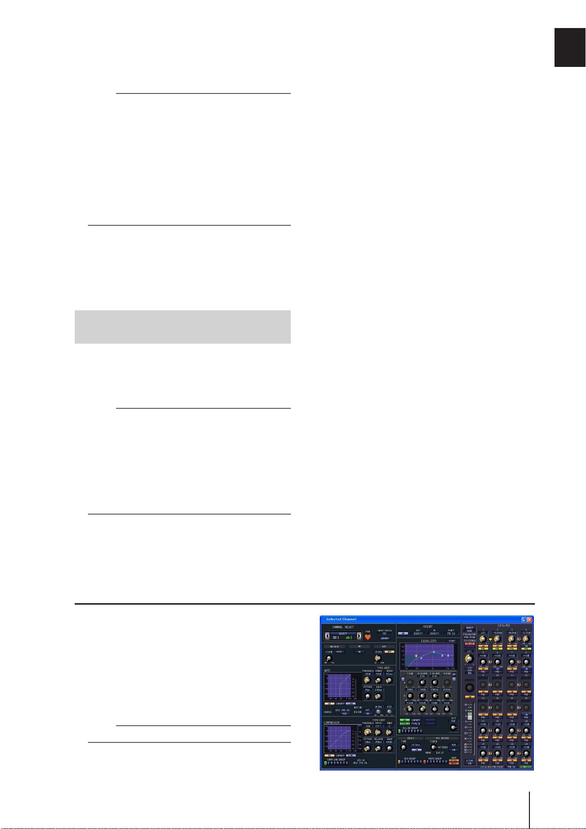
Using the Selected Channel section.....65
About the SELECTED CHANNEL section .......................... 65
Items in the SELECTED CHANNEL section ....................... 65
GROUP ........................................................................................ 65
CHANNEL SELECT ................................................................... 66
DELAY ......................................................................................... 66
GAIN/ATTENUATION/ø (Gain / Attenuation / Phase) ........ 67
NOISE GATE............................................................................... 67
STEREO ....................................................................................... 68
COMPRESSOR ........................................................................... 68
HPF (High Pass Filter)................................................................ 69
EQUALIZER................................................................................ 69
Operations in the SELECTED CHANNEL section .............. 70
Selecting a channel and editing its parameters ......................... 70
Compressor operations............................................................... 71
Gate operations ........................................................................... 72
EQ/HPF operations..................................................................... 73
8
Input Patch / Output Patch operations .74
Changing the input patch settings .................................. 74
Changing the output patch settings................................ 75
Inserting an external device into a channel...................... 77
Connecting an external device for insertion ............................. 77
Patching the insert-out and insert-in ........................................ 78
Directly outputting the signal of an input channel .......... 80
6
PM5D/PM5D-RH V2 / DSP5D Owner’s Manual
Table of Contents
Page 7

7
Grouping and linking............................81
9
About DCA Groups and Mute Groups .............................81
Items in the ASSIGN MODE section ................................. 81
Items in the DCA strip...................................................... 81
Using DCA Groups........................................................... 82
Assigning channels to DCA groups............................................82
Controlling DCA groups.............................................................83
Using mute groups .......................................................... 83
Assigning channels to mute groups............................................ 83
Controlling mute groups.............................................................84
Using the Mute Safe function .....................................................84
Using EQ Link and Compressor Link ................................ 85
10
Scene memory....................................87
About scenes ................................................................... 87
Items in the SCENE MEMORY section .............................. 88
Using scene memories ..................................................... 89
Storing a scene.............................................................................. 89
Recalling a scene...........................................................................90
Using PREVIEW mode ...................................................... 90
Using the Auto Store function.......................................... 91
Using the Direct Recall function ....................................... 91
Using the Selective Recall function................................... 92
Using the Recall Safe function.......................................... 94
Using the Fade function................................................... 95
Using the Tracking Recall function ................................... 96
Using the Global Paste function ....................................... 97
11
Monitor and Cue................................99
Graphic EQ and Parametric EQ .......118
15
Patching the GEQ modules............................................ 118
Expanding the GEQ modules......................................... 119
Basic graphic EQ operations .......................................... 119
Controlling the graphic EQ from the display ......................... 119
Controlling the graphic EQ from the DCA section................ 120
Basic parametric EQ operations ..................................... 121
Controlling the parametric EQ from the display.................... 121
Controlling the parametric EQ from the SELECTED
CHANNEL section.......................................................... 122
16
Remote control ................................ 123
MIDI on the PM5D ........................................................ 123
Using program changes to control events ..................... 123
Using control changes to control events........................ 125
Using the MIDI Remote function ................................... 127
Assigning MIDI messages to controllers ................................. 127
Using MIDI remote channels................................................... 131
Transmitting MIDI events when you switch scenes........ 132
Using GPI (General Purpose Interface) ........................... 133
Using GPI IN ............................................................................. 133
Calibrating the GPI IN ports .................................................... 135
Using GPI OUT......................................................................... 136
17
Using memory cards........................138
Using memory cards with the PM5D............................. 138
Saving files to a memory card........................................ 138
Loading files from a memory card ................................. 140
About the MONITOR and CUE sections........................... 99
Using the Monitor function ........................................... 100
Items in the MONITOR section...............................................100
Monitoring a signal....................................................................101
Using the Cue/Solo functions ........................................ 102
Items in the CUE section...........................................................102
About CUE mode and SOLO mode.........................................102
Cue and Solo groups..................................................................103
Using the Cue function .............................................................104
Using the Solo function.............................................................104
12
Talkback and Oscillator....................105
About the TALKBACK/OSCILLATOR sections.................. 105
Items in the TALKBACK/OSCILLATOR sections..................105
Using talkback ............................................................... 106
Using the oscillator ........................................................ 107
13
Meters...............................................108
Items in the meter section ............................................. 108
Switching the meter display........................................... 108
Switching the metering point ........................................ 109
Specifying the metering point for input channels...................109
Specifying the metering point for output channels ................109
Viewing the gain reduction of the internal gates and
compressors....................................................... 110
Viewing the gain reduction for input channels .......................110
Viewing the gain reduction for output channels.....................110
Effects ...............................................111
14
About the internal effects............................................... 111
Using an internal effect via a MIX bus ............................ 112
Inserting an internal effect into a channel ...................... 113
Basic operations in the effect screen .............................. 114
Recalling settings from the effect library..................................114
Editing the effect parameters ....................................................115
Storing settings in the effect library ..........................................115
Using the Tap Tempo function ......................................116
Using the Freeze effect................................................... 117
18
Surround pan ...................................142
About surround pan ...................................................... 142
Bus configuration and operation in surround mode ...... 143
About the surround buses ........................................................ 143
How the MIX section will operate ........................................... 143
Basic settings for surround buses ................................... 144
Controlling surround pan .............................................. 145
Notes regarding surround pan ...................................... 147
Other functions................................148
19
Using the user defined keys ........................................... 148
Items in the USER DEFINED section ..................................... 148
Assigning functions to the User Defined keys ........................ 148
Executing functions assigned to the User Defined keys......... 149
Using the FADER MODE section .................................... 149
Items in the FADER MODE section........................................ 149
Assigning the FADER MODE section layer ............................149
Switching the FADER MODE section layer............................ 150
Locking the PM5D (Security functions).......................... 151
Setting the System Password or Console Password................ 151
Using Parameter Lock or Console Lock.................................. 152
Using cascade connections ............................................ 153
Example of cascade connections between the PM5D and
DSP5D.............................................................................. 153
Example of cascade connections between PM5D units .........153
Specifying the DSP5D’s machine ID number......................... 153
Basic settings for cascade connection ...................................... 154
Selecting the buses used for cascade connection .................... 156
Connecting the PM5D to your computer via USB ......... 158
Caution when using the USB TO HOST connector .............. 158
Connecting the DSP5D to your computer via Ethernet . 159
Initializing the PM5D’s internal memory........................ 160
Initializing the DSP5D’s internal memory....................... 160
Adjusting the faders and input/output gain
(Calibration) ...................................................... 161
Calibrating the faders................................................................ 161
Adjusting the analog input gain (PM5D-RH model only).... 162
Adjusting the output gain......................................................... 162
PM5D/PM5D-RH V2 / DSP5D Owner’s Manual
Table of Contents
Page 8

Table of Contents — Reference section
Information shown in the display.......... 163
Upper part of the display (always visible)....................... 163
Main area of the display ................................................ 164
Lower part of the display (always visible) ....................... 164
Function menu........................................ 165
Global functions...................................... 166
EFFECT functions ........................................................... 166
EFFECT PARAM (Effect parameter) screen ...........................166
EFFECT ASSIGN screen............................................................168
EFFECT LIBRARY screen .........................................................169
PLUG-IN screen.........................................................................170
GEQ function................................................................. 170
GEQ PARAM (GEQ parameter) screen ..................................170
GEQ ASSIGN screen .................................................................173
GEQ LIBRARY screen ...............................................................174
SCENE function ............................................................. 175
SCENE screen.............................................................................175
EVENT LIST screen...................................................................177
SELECTIVE RECALL screen ....................................................180
RECALL SAFE screen ................................................................182
FADE TIME screen....................................................................184
TRACKING RECALL screen ....................................................186
GLOBAL PASTE screen ............................................................187
MIDI REMOTE function ................................................. 188
MIDI SETUP screen ..................................................................188
MIDI PGM CHANGE (MIDI program change) screen ........190
MIDI CTRL CHANGE (MIDI control change) screen..........191
MIDI REMOTE screen..............................................................192
GPI screen...................................................................................194
FADER START screen............................................................... 196
TRANSPORT screen .................................................................198
DME CONTROL screen ...........................................................199
UTILITY function ............................................................ 204
PREFERENCE 1/2 screens ........................................................204
USER DEFINE screen................................................................208
SAVE screen ...............................................................................211
LOAD screen ..............................................................................215
FADER ASSIGN screen .............................................................217
SECURITY screen......................................................................218
SYS/W.CLOCK function ................................................. 219
WORD CLOCK screen..............................................................219
MIXER SETUP screen...............................................................221
CASCADE screen....................................................................... 226
HA (Head Amp) screen.............................................................228
OUTPUT PORT ATT (Output port attenuation) screen ......229
DITHER screen ..........................................................................229
HA LIBRARY screen..................................................................230
METER function ............................................................. 231
INPUT METER screen ..............................................................231
OUTPUT METER screen..........................................................232
INPUT GR (Input Gain Reduction) screen.............................233
OUTPUT GR (Output Gain Reduction) screen .....................234
MON/CUE function ....................................................... 234
TALKBACK screen ....................................................................234
OSCILLATOR screen ................................................................236
2TR I/O screen ...........................................................................237
MONITOR screen .....................................................................238
CUE/SOLO screen .....................................................................240
Output functions .................................... 243
OUTPUT PATCH function .............................................. 243
OUTPUT PATCH screen ......................................................... 243
INSERT PATCH screen............................................................ 244
INSERT POINT screen............................................................. 246
NAME screen............................................................................. 247
OUTPUT PATCH LIBRARY screen ....................................... 247
OUTPUT INSERT function.............................................. 248
INSERT IN MIX 1-24 screen ................................................... 248
INSERT IN MATRIX/STEREO/MONITOR screen ..............248
HA LIBRARY screen ................................................................. 249
OUTPUT EQ function .................................................... 250
EQ PARAM (EQ Parameter) screen........................................ 250
MIX 1-24 screen ........................................................................ 251
MATRIX/STEREO screen ........................................................ 251
OUTPUT EQ LIBRARY screen................................................ 252
OUTPUT COMP function............................................... 253
COMP PARAM (Compressor parameter) screen.................. 253
MIX 1-24 screen ........................................................................ 255
MATRIX/STEREO screen ........................................................ 255
COMP LIBRARY (Compressor library) screen...................... 256
OUTPUT DELAY function ............................................... 257
MIX 1-24 screen ........................................................................ 257
MATRIX/STEREO screen ........................................................ 257
OUTPUT DCA/GROUP function..................................... 258
DCA GROUP ASSIGN screen ................................................. 258
MUTE GROUP ASSIGN screen .............................................. 259
EQ LINK ASSIGN screen ......................................................... 260
COMP LINK ASSIGN (Compressor link assign) screen ....... 261
MATRIX/ST function...................................................... 262
MATRIX/ST ROUTING screen............................................... 262
MIX to MATRIX VIEW screen................................................ 264
LCR screen ................................................................................. 267
SURR SETUP screen................................................................. 268
OUTPUT VIEW function ................................................. 270
CH VIEW (Channel view) screen............................................ 270
SIGNAL FLOW screen ............................................................. 272
FADER VIEW screen ................................................................273
CH JOB (Channel job) screen.................................................. 274
OUTPUT CH LIBRARY screen ............................................... 275
PM5D/PM5D-RH V2 / DSP5D Owner’s Manual
8
Table of Contents
Page 9

Input functions ........................................277
Appendices.............................................. 317
INPUT PATCH function .................................................. 277
INPUT PATCH screen..............................................................277
DIRECT OUT PATCH screen..................................................278
INSERT PATCH screen ............................................................279
INSERT/DIRECT OUT POINT screen ...................................281
NAME screen .............................................................................282
INPUT PATCH LIBRARY screen ............................................283
INPUT HA/INSERT function............................................ 283
CH 1-24 (Input channel 1-24) screen ......................................283
CH 25-48 (Input channel 25-48) screen ..................................283
STIN/FXRTN (ST IN/FXRTN channel) screen ......................283
INSERT 1-24 screen...................................................................284
INSERT 25-48 screen.................................................................284
INSERT STIN screen .................................................................284
HA LIBRARY screen..................................................................285
INPUT ø/EQ function ..................................................... 286
EQ PARAM (EQ parameter) screen ........................................286
EQ 1-24 screen ...........................................................................287
EQ 25-48 switch .........................................................................287
EQ STIN/FXRTN screen...........................................................287
ø/ATT 1-48 (Phase/Attenuation 1-48) screen.........................288
ø/ATT STIN/FXRTN (Phase/Attenuation STIN/FXRTN)
screen ................................................................................288
INPUT EQ LIBRARY screen ....................................................289
INPUT GATE/COMP function......................................... 289
GATE PARAM (Gate parameter) screen.................................289
COMP PARAM (Compressor parameter) screen ..................291
CH 1-12 (Input channel 1–12) screen .....................................293
CH 13-24 (Input channel 13–24) screen .................................293
CH 25-36 (Input channel 25–36) screen .................................293
CH 37-48 (Input channel 37–48) screen .................................293
ST IN (ST IN channel) screen...................................................293
GATE LIBRARY screen.............................................................294
COMP LIBRARY (Compressor library) screen ......................295
INPUT DELAY function................................................... 295
CH 1-24 (Input channel 1–24) screen .....................................295
CH 25-48 (Input channel 25–48) screen .................................295
ST IN (ST IN channel) screen...................................................295
INPUT DCA/GROUP function......................................... 296
DCA GROUP ASSIGN screen ..................................................296
MUTE GROUP ASSIGN screen...............................................297
EQ LINK ASSIGN screen..........................................................298
COMP LINK ASSIGN (Compressor link assign) screen .......299
PAN/ROUTING function ................................................ 299
CH to MIX (Channel to mix) screen .......................................299
MIX SEND VIEW screen ..........................................................305
FIX ASSIGN VIEW screen ........................................................307
LCR screen..................................................................................308
SURR PARAM (Surround parameter) screen.........................309
SURR VIEW (Surround view) screen ......................................310
M/S screen ..................................................................................311
INPUT VIEW function ..................................................... 311
CH VIEW (Channel view) screen ............................................311
SIGNAL FLOW screen ..............................................................313
FADER VIEW screen.................................................................314
CH JOB screen ...........................................................................314
INPUT CH LIBRARY (Input channel library) screen............316
EQ Library List................................................................ 317
GATE Library List............................................................ 318
Compressor Library List ................................................. 319
Dynamics Parameters .................................................... 321
GATE section............................................................................. 321
COMP section ........................................................................... 322
Effect Library List............................................................ 324
Effects Parameters.......................................................... 325
Effects and tempo synchronization ......................................... 336
Scene Memory/Effect Library to Program Change Table
Parameters that can be assigned to control changes ..... 341
Control change parameter assignments ........................ 343
NRPN parameter assignments ....................................... 360
Channel Library List ....................................................... 364
List of parameters available for Pair, Recall Safe or
OUTPUT ISOLATION operation ......................... 365
MIDI Data Format.......................................................... 368
Warning Messages......................................................... 377
Error Messages............................................................... 379
Troubleshooting ............................................................ 380
General Specifications.................................................... 381
PM5D/PM5D-RH..................................................................... 381
DSP5D........................................................................................ 383
Input/output characteristics........................................... 384
Electrical characteristics ................................................. 389
PM5D/PM5D-RH..................................................................... 389
DSP5D........................................................................................ 391
Other Functions............................................................. 393
Pin Assignment.............................................................. 394
Dimensions.................................................................... 395
MIDI Implementation Chart .......................................... 396
Index ............................................................................. 397
PM5D/PM5D-RH Block Diagram ...................End of Manual
DSP5D Block Diagram ...................................End of Manual
PM5D Level Diagram.....................................End of Manual
PM5D-RH Level Diagram ...............................End of Manual
DSP5D Level Diagram ...................................End of Manual
.. 337
• The illustrations and screen displays as shown in this
Owner’s Manual are for instructional purposes only,
and may be different from the ones on your device.
• The company names and product names in this
Owner’s Manual are the trademarks or registered
trademarks of their respective companies.
PM5D/PM5D-RH V2 / DSP5D Owner’s Manual Table of Contents 9
Page 10

Operating section
1 Introduction
Thank you
Thank you for purchasing the Yamaha PM5D digital mixing console and/or Yamaha DSP5D digital mixing system. In order
to take full advantage of the PM5D/DSP5D’s superior functionality and enjoy years of trouble-free use, please read this manual before you begin using the product. After you have read the manual, keep it in a safe place.
An overview of the PM5D system
The PM5D is an expandable digital mixing console with the following features.
❏ Full digital SR mixing system
The PM5D is a full-digital SR mixing console that takes
advantage of cutting-edge digital audio processing technology. 24-bit linear AD/DA converters are used to deliver up
to 110 dB of dynamic range and amazing sound quality. As
input channels, it provides 48 monaural channels, four stereo channels, and four stereo channels for effect return. As
output channels, it provides 24 MIX channels, eight
MATRIX channels, and two STEREO channels. The PM5D
can be used in a wide range of applications. You can assign
desired channels to be controlled by the eight DCA faders
on the panel, and use them as group faders.
❏ PM5D model and PM5D-RH model
In addition to the standard PM5D model that provides
manual control of the head amp for each input, the
PM5D-RH model is also available, providing programmable control of head amp input sensitivity and phantom
power settings. You can choose the model appropriate for
your situation and budget.
❏ Cutting-edge user interface
For the input channels and STEREO A/B channels, dedicated channel strips are provided where you can operate
the fader, pan, cue, and on/off controls. For MIX channels
and MATRIX channels, encoders allow you to control the
send level and master level. The PM5D allows quick and
intuitive operation just as on an analog mixer. In addition,
you can use the SELECTED CHANNEL section to manually control the principal parameters (delay, EQ, gate,
compressor) of the desired channel.
❏ Eight effect modules / Twelve graphic
EQ modules
Eight high-quality multi-effect modules are built in. Effects
such as reverb, delay, multiband compressor, and various
modulation effects can be routed via internal buses or
inserted into the desired channel. 31-band graphic EQ
(alternatively, 8-band parametric EQ) can also be inserted
into any channel or any output.
❏ Add-On effects provided as standard
As effect types, the channel strip package (COMP276/276S,
COMP260/260S, EQ601), master strip package (OPEN
DECK), and reverb package (REV-X) are provided as
standard.
❏ Scene memories and libraries
Mix parameters and internal effect settings can be stored in
memory as up to 500 scenes for immediate recall. Effects,
input/output patching, input channel/output channel settings, internal head amp (PM5D-RH model only) or
external head amp settings can be stored in various libraries, independently of scenes.
❏ Digital cascade connection
Up to four PM5D units, or one PM5D and one Yamaha
DM2000/02R96 unit, can be cascade-connected to share
buses in the digital domain. In particular when PM5D
units are cascaded together, operations such as scene saving and recall can also be linked. DME64N can also be used
as inserts or as extended signal processors via a cascade
connection.
❏ Surround panning
Surround pan functionality allows multi-channel playback
systems to be used, letting you place the signal of an input
channel in two-dimensional space, or move the sound
image forward/backward and left/right. 3-1ch, 5.1ch, and
6.1ch surround modes are available.
❏ I/O card expansion
The rear panel provides four slots in which separately sold
mini-YGDAI cards can be installed. AD cards, DA cards, or
digital I/O cards can be installed in these slots to add inputs
and outputs.
❏ Expansion via the DSP5D
A maximum of two DSP5D digital mixing systems can be
cascade-connected to a PM5D to expand the inputs and
outputs. You can also connect a Yamaha DCU5D digital
cabling unit between the PM5D and DSP5D, and locate the
DSP5D remotely.
10 PM5D/PM5D-RH V2 / DSP5D Owner’s Manual Operating section
Page 11
Differences between the PM5D model and the PM5D-RH model
The PM5D is available as the standard PM5D model or as the PM5D-RH model which allows internal head amp settings to be
programmed. These models differ as follows.
1
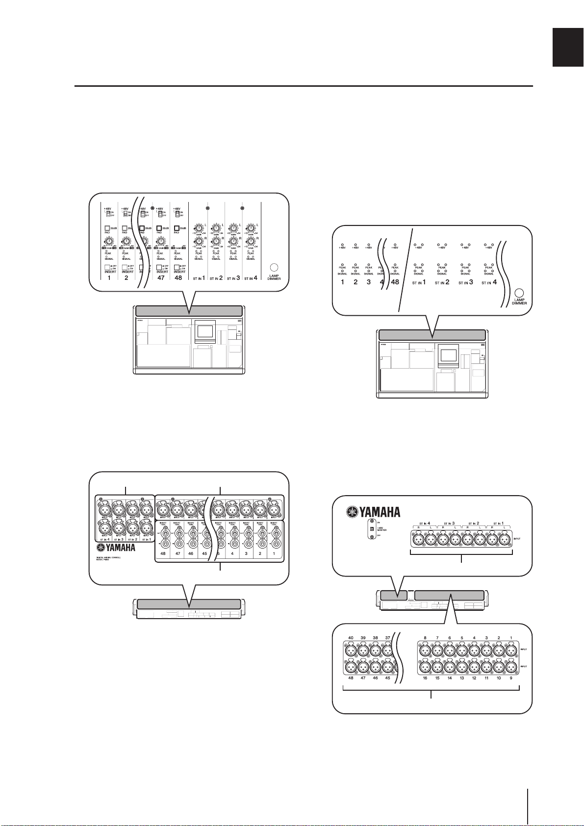
❏ PM5D model
• Head amp adjustments (input sensitivity settings,
phantom power (+48V) on/off) for the analog inputs
(INPUT jacks 1–48, ST IN jacks 1–4) are performed
manually, using the controls of the top panel.
• Insert jacks (INSERT IN/OUT jacks) for the monaural
analog inputs (INPUT jacks 1–48) are provided on the
rear panel, allowing external effect processors to be
inserted in the analog domain.
• ST IN jacks 1–4 are only for line level.
• There is no +48V MASTER switch.
INPUT jacks 1–48ST IN jacks 1–4
❏ PM5D-RH model
• Head amp adjustments (input sensitivity settings,
phantom power (+48V) on/off) for the analog inputs
are controlled from within the screen via software. For
this reason, the top panel does not have head amp controls; instead, LEDs showing the presence or absence of
a signal are provided. Head amp settings can be saved
in a library and recalled at any time.
• Insert jacks for the analog inputs are not provided.
• ST IN jacks 1–4 support mic levels through line levels.
Phantom power can also be supplied to ST IN jacks 1–
4.
• The +48V MASTER switch turns all phantom power
(+48V) on/off.
Introduction
INSERT IN/OUT jacks 1–48
PM5D/PM5D-RH V2 / DSP5D Owner’s Manual Operating section 11
ST IN jacks 1–4
INPUT jacks 1–48
Page 12

1 Introduction
About the channel structure of the PM5D
The PM5D provides the following input channels and output channels.
❏ Input channels
This section processes input signals and sends them to the
STEREO bus or MIX buses. There are three types of input
channel, as follows.
• Input channels 1–48
These channels are used to process monaural signals.
By default, the input signals from the monaural analog
input jacks (INPUT jacks 1–48) are assigned to these
channels.
• ST IN channels 1–4
These channels are used to process stereo signals. By
default, the input signals from the stereo analog input
jacks (ST IN jacks 1–4) are assigned to these channels.
• FX RTN channels 1–4
These channels are used mainly to process the return
signals (stereo) from the internal effects. By default, the
left/right output channels of internal effects 1 through
4 are assigned to these channels.
Hint
Signal assignments to the input channels can be changed as
desired.
❏ Output channels
This section mixes the signals sent from input channels
etc., and sends them to the corresponding output jacks or
output buses. There are three types of output channel, as
follows.
• MIX channels 1–24
These channels process signals sent from input channels to MIX buses. In the initial state, output signals are
assigned to MIX OUT jacks 1–24. These channels are
used mainly for foldback or as sends to external effects.
The signals of MIX channels 1–24 can also be sent to
the STEREO bus or MATRIX buses.
• MATRIX channels 1–8
These process the signals sent from MIX channels or
STEREO A/B channels to MATRIX buses, and output
them from the MATRIX OUT jacks. This allows MIX
channels or STEREO A/B channels to be mixed at the
desired balance for output.
• STEREO A/B channels
These process the signals sent from input channels or
MIX channels, and output them to STEREO OUT
jacks A/B. These channels are used as the main stereo
outputs. Normally, the same signal is sent from the
STEREO A and B channels. However, it is also possible
to use the STEREO B channel as the center channel for
three-channel L/C/R playback.
About the DSP5D
The DSP5D is a digital signal processing (DSP) system
expanding the inputs and outputs of the PM5D.
• Its audio processing capability is equivalent to that of
the PM5D-RH. As analog audio input/output jacks, it
provides INPUT jacks 1–48, ST IN jacks 1–4, and
OMNI OUT jacks 1–24.
• Up to two DSP5D units can be cascade-connected to
one PM5D. By connecting it with DSP5D units, the
PM5D system can be expanded to a maximum of 168
channels of input (144 channels + 12 ST).
• By switching the control target on the PM5D, the
DSP5D can be seamlessly controlled in the same way as
the PM5D itself.
• You can use DSP5D Editor application software to
remotely control and edit the parameters of the
DSP5D. Only Windows computers are supported.
• The DSP5D can be connected to a Yamaha DCU5D
digital cabling unit and placed on stage, and operated
remotely from the PM5D.
• The front panel provides two slots in which you can
install separately sold mini-YGDAI cards to add inputs
and outputs in a variety of digital formats.
Differences with the PM5D
❏ Connectors and interfaces not found on
the DSP5D
• INSERT IN/OUT jacks, MIX OUT jacks, LAMP jacks,
MONITOR OUT jacks, CUE OUT jacks, STEREO
OUT A/B jacks, MATRIX OUT jacks, 2TR IN ANALOG jacks, TIME CODE INPUT jack, USB TO HOST
connector, GPI connector, RS422 REMOTE connector, HA REMOTE connector, MIDI IN/THRU/OUT
connectors, 2TR OUT DIGITAL jack, 2TR IN DIGITAL jack, SLOT 3–4, MEMORY CARD slot, MOUSE
connector, KEYBOARD connector, PHONES jack
• Controllers such as faders, display devices such as
meters. LCD display, +48V MASTER switch (PM5DRH), 75Ω ON/OFF switch
❏ Connectors and interfaces found only
the DSP5D
• OMNI OUT jacks, CASCADE IN/OUT RJ-45 connectors, NETWORK connector, AC IN connector
• POWER switch, mode switch, FAN switch
About the connectors: Since the DSP5D does not have
the functionality for the connectors with which DSP5D
is not equipped, these functions and connectors are not
shown in the screen of the PM5D or DSP5D Editor.
12 PM5D/PM5D-RH V2 / DSP5D Owner’s Manual Operating section
Page 13
About the interface: Since the DSP5D does not have
controllers such as faders or the LCD display, it is operated from the PM5D or DSP5D Editor.
Note
• The explanations in chapter 5 and following of this Owner’s
Manual are based on the functionality and operating procedures of the PM5D. Supplementary explanations regarding
the DSP5D are added only in cases where there is a significant difference in functionality or operating procedure.
However, in cases where it is obvious that the abovedescribed differences would make clear differences in operation or in the on-screen display, explanations for the
DSP5D will be omitted.
• There are some differences between the PM5D and DSP5D
in the I/O cards that are supported. For the most recent
information regarding I/O cards, refer to the following
Yamaha website.
http://www.yamahaproaudio.com/
❏ Connection to a computer
The PM5D can be connected to a computer via a USB
cable from its USB TO HOST connector, but the DSP5D
can be connected to a computer via an Ethernet CAT5
cable from its NETWORK connector.
Regarding cascade connections between the PM5D and DSP5D
By bi-directionally cascade-connecting the PM5D and
DSP5D, you can share MIX buses 1–24, STEREO A/B
buses, and CUE buses.
For details on cascade connections, refer to p.153.
Note
• Cascade connection with the DSP5D is possible only for
PM5D V2.0 or later. If you’re using earlier version than V2.0,
you will need to upgrade to PM5D V2.0 or later. You can
download the most recent firmware from the following
Yamaha website.
http://www.yamahaproaudio.com/
• Connectors and interfaces not found on the DSP5D cannot
be controlled from the PM5D. For example, the MONITOR
[LEVEL] and MONITOR [PHONES] knobs found on the
PM5D’s top panel are always operated at the level of the
PM5D.
❏ Controlling the DSP5D
• As the target of control from the PM5D’s panel and
screen, you can recall machine #1 (PM5D), machine #2
(first DSP5D), or machine #3 (second DSP5D) as
desired. For details on operation, refer to p.153.
• Functions assigned to the user-defined keys or the
FADER MODE section can be used to select the
DSP5D as the target machine to be operated (➥ p.148,
149). Operations can be performed from the panel of
the PM5D itself or from DSP5D Editor connected to
the DSP5D.
❏ Operation when cascade-connected
• Output channels
In general, operations for the output channels of cascade-connected buses will be linked between machines.
(You can also specify that they not be linked.) This
means that you can operate the system as if it were a
single console with an expanded number of inputs.
However, since the inserts to output channels will also
be duplicated, inserted GEQ modules and effects may
also be consumed in duplicate or triplicate. (Separate
GEQ modules or effects are inserted into the linked
buses on each machine.)
• Scene memories and libraries
Scene memory and library data is stored on each
machine. When a scene or a library associated with a
scene is stored or recalled, the same scene/library number will be stored/recalled on all machines. When the
cascade-connection becomes active, the PM5D’s
library data not associated with a scene will be sent to
each DSP5D to synchronize the libraries. The data on
cascade-connected machines can also be saved together
to a memory card.
• Effects
The DSP5D provides GEQ modules and effects that are
equivalent to those on the PM5D, but since the connections between machines are bus cascade
connections, inserts into input channels are limited to
being within each machine.
• DCA groups / Mute groups
These will operate in tandem for cascade-connected
PM5D/DSP5D machines. (➥ p.156)
• CH JOB function
Channel copy operations between the PM5D/DSP5D
can be performed from the PM5D front panel. However, channels can be moved using the INPUT VIEW
function only within each machine. (➥ p.274, 314)
1
Introduction
About PM5D Editor and DSP5D Editor
These programs are application software for operating the
PM5D/DSP5D’s functionality from a computer. You can
use this software to remotely control and edit the parameters of the PM5D/DSP5D.
The USB-MIDI driver (for the PM5D) or DME-N Network driver (for the DSP5D) required for connection with
a computer, as well as the PM5D/DSP5D editor, can be
downloaded from the following Yamaha website.
http://www.yamahaproaudio.com/
Note
DSP5D Editor supports only Windows computers.
PM5D/PM5D-RH V2 / DSP5D Owner’s Manual Operating section 13
Page 14

1 Introduction
Firmware versions
You can download the most recent firmware from the following Yamaha website.
http://www.yamahaproaudio.com/
For either the PM5D or the DSP5D, you can check the firmware version in the UTILITY function PREFERENCE 2 screen
(➥ p.207).
Major new functionality in PM5D firmware V2.0
The major new functionality and improvements that were added in conjunction with the upgrade to firmware V2.0 are as
follows.
❏ Basic functionality and panel operations
• You can now control the DSP5D from the PM5D’s
panel. (➥ p.153)
• On/off operations of the channel selected in the
FADER MODE section can now be operated from the
DCA [MUTE] key.
• Even if the FADER [FLIP] key is on, you can now use
the encoders to control the panning of the signal sent
to the MIX buses, the head amp gain, or the attenuators. (➥ p.49)
• If there is no vacant library number when you store the
selected scene as NEW, it will now be impossible to
save the scene; this prevents an existing library item
from being overwritten.
• Remote control of the DME64N/24N (firmware V2.0
and later) is now faster. In particular, operation is
faster when connected via an MY16-C or MY16-CII
card (supported from V1.2).
• As parameters that can be operated in the screen,
MONITOR LEVEL and CUE LEVEL have been added.
You can now assign these to the faders of the DCA strip
so that the monitor or cue levels can be adjusted.
(➥ p.149)
❏ EFFECT functions
• Add-On Effects (COMP276/276S, COMP260/260S,
EQ601, OPEN DECK) and DE-ESSER have been
added.
•A DSP CONFIGURATION option has been added to
the EFFECT ASSIGN screen and to the GEQ function
GEQ ASSIGN screen, allowing internal effects 1–8 to
be used as graphic EQ or parametric EQ.
(➥ p.168, 173)
• When the panel [SEL] key is pressed in the EFFECT
PARAM screen, or when a [SEL] key is turned on via a
linking setting, the effect module inserted in that channel will automatically be selected.
• If you’ve used the tap tempo function to specify the
tempo in the EFFECT PARAM screen and then edited
the DELAY parameter, the tempo will now stay
unchanged.
❏ GEQ functions
• Options have been added to the GEQ PARAM screen,
allowing you to switch a graphic EQ to a parametric
EQ. (➥ p.170)
• Not only when the panel [SEL] key is pressed in the
GEQ PARAM screen but also when a [SEL] key is
turned on via a linking setting, the GEQ module
inserted in that channel will automatically be selected.
• When you insert a GEQ in the GEQ PARAM screen,
insert-in will automatically be turned on for that channel, and will be automatically turned off when you
remove the GEQ.
❏ SCENE functions
• In the SCENE screen, you can now specify “read-only”
scenes that will not be overwritten when you load
scenes from a memory card. (➥ p.175)
• In the SCENE screen, a DELAY field has been added,
allowing you to specify the timing of the program
change or MIDI events that are transmitted when the
scene is recalled. (➥ p.175)
• In the SELECTIVE RECALL screen and the RECALL
SAFE screen, the ON parameter has been added as a
channel parameter that can be included in or excluded
from recall operations. (➥ p.180, 182)
• In the SELECTIVE RECALL screen and RECALL SAFE
screen, separately from the conventional Recall Safe
functionality, an OUTPUT ISOLATION field has been
added, so that output channels and parameters to be
excluded from recall operations can be stored in
SETUP memory (which is not affected by memory
card load operations). (➥ p.180, 182)
❏ SYS/W.CLOCK functions
• In the MIXER SETUP screen, a VIRTUAL SOUNDCHECK button has been added, allowing you to
temporarily switch the input signals without affecting
the scene memory (input patching). For example, this
allows you to perform a sound check using prerecorded material played back by a DAW connected to
a slot, instead of the analog input material received via
the INPUT jacks. (➥ p.221)
• In the OUTPUT ATT PORT screen, a ø (phase) button has been added, allowing you to switch the phase
between normal and reverse for each output channel or
I/O channel output port.
❏ UTILITY functions
• In the PREFERENCE 1 screen, a DCA MUTE TARGET option has been added, allowing you to specify
that the DCA [MUTE] key will mute the send to the
MIX bus. (➥ p.205)
• In the PREFERENCE 1 screen, an ATT OPERATION
ON PANEL option has been added, allowing you to
prevent the panel encoders from operating the attenuators. (➥ p.206)
• In the PREFERENCE 1 screen, a MIX SEL/ENCODER
MODE LINK option has been added, allowing you to
14 PM5D/PM5D-RH V2 / DSP5D Owner’s Manual Operating section
Page 15

link selection of MIX channels with selection of MIX
SEND SELECT keys. (➥ p.206)
• In the USER DEFINE screen, functions such as DSP5D
CONTROL and ENCODER MODE KEY have been
added to the functions that can be assigned to userdefined keys. (➥ p.208)
• In the FADER ASSIGN screen, options have been
added, allowing you to use the STEREO/DCA strip section to control the monitor/cue level and on/off status.
(➥ p.217)
• In the FADER ASSIGN screen, you can now assign the
desired channels of the DSP5D as well. (➥ p.217)
• In the SECURITY screen, a LOAD LOCK function has
been added, allowing you to disable loading for each
type of file. (➥ p.218)
• In the SECURITY screen, a RECALL LOCK option has
been added, allowing you to lock parameters so that
they will not be changed when a scene or library is
recalled. (➥ p.218)
❏ Input/output functions
• In the OUTPUT PATCH function OUTPUT PATCH
screen, you can now change the patching of output
channels to MIX OUT jacks 1–24. (➥ p.243)
• In the OUTPUT PATCH function INSERT POINT
screen and the INPUT PATCH function INSERT/
DIRECT OUT POINT screen, a SET ALL button and
CLEAR ALL button have been added, allowing you to
turn all channels on/off in a single operation.
(➥ p.246, 281)
• In the OUTPUT PATCH function, a NAME screen has
been added, allowing you to assign names to output
channels for display in various screens (supported from
V1.2). (➥ p.247)
• In the INPUT VIEW function CH JOB screen, channel
settings can now be moved as well as copied. (➥ p.314)
• In the INPUT PATCH function INSERT/DIRECT
OUT POINT screen, PRE ATT has been added as a
direct output transmit location. (➥ p.282)
• In the PAN/ROUTING function MIX SEND VIEW
screen, the send position (PRE/POST) of the signal
sent to the MIX bus is now indicated by the color of the
bar graph. (➥ p.306)
• You can now set a Q of up to 16 for the parametric EQ
in the input channels, output channels, and GEQ
modules.
• You can now set a threshold level of down to –72 dB
for an input channel GATE.
1
Introduction
Regarding word clock synchronization
The signal used to synchronize digital audio signal processing is called “word clock.” Normally, one device transmits
a reference word clock signal, and the other devices receive
this word clock signal and synchronize to it.
In order to transmit or receive digital audio signals to or
from an external device via the PM5D/DSP5D’s digital
input/output jacks or via a digital I/O card installed in a
slot, the word clock must be synchronized between the
devices. Be aware that if the word clock is not synchronized, the signals will not be transmitted correctly, and
unpleasant noise will occur.
Hint
• For details on synchronizing the word clock of the PM5D/
DSP5D and external devices, refer to the explanation of
word clock in Operating section “Chapter 4. Connections
and setup” (
CLOCK screen” (
• As an exception, digital signals that are not synchronized
with the PM5D/DSP5D can be input via a digital I/O card
that contains a sampling rate converter, or via the 2TR IN/
OUT DIGITAL jacks.
How this manual is organized
This owner’s manual is divided into the following three
sections.
❏ Operating section
This section explains the items on the front and rear panels, connections and setup, and how to operate the PM5D’s
basic functionality. In particular if you have not operated a
digital console before, we recommend that you read chapters 2 through 7 first.
❏ Reference section
This section explains the functionality and operation for all
of the PM5D’s screens. Refer to this section when you want
to learn about the items in the screens.
❏ Appendices
This contains various information such as library lists,
parameter lists for the internal effects, the MIDI data format, and lists of warning messages and error messages.
Conventions in this manual
In this manual, non-locking panel switches that you press
are called “keys,” and those that change their on/off status
when you push them in (locking types) are called
“switches.” Of the control knobs on the panel, those that
turn from a minimum value to a maximum value are
called “knobs,” while those that turn endlessly are called
“encoders.”
Controls located on the panel are enclosed in square brackets [ ] (e.g., [CUE] key, [PAD] switch) in order to
distinguish them from the buttons and knobs displayed in
the screen. For some controls, the section name is listed
before the [ ] (e.g., CH [ON] key, EQ [FREQUENCY]
encoder).
Unless otherwise specified, references to the PM5D apply
to both the PM5D model and the PM5D-RH model. If
specifications differ between the PM5D model and the
PM5D-RH model, such differences will be noted each time
they occur.
➥
p.38), and to the Reference Section “WORD
➥
p.219).
PM5D/PM5D-RH V2 / DSP5D Owner’s Manual Operating section 15
Page 16
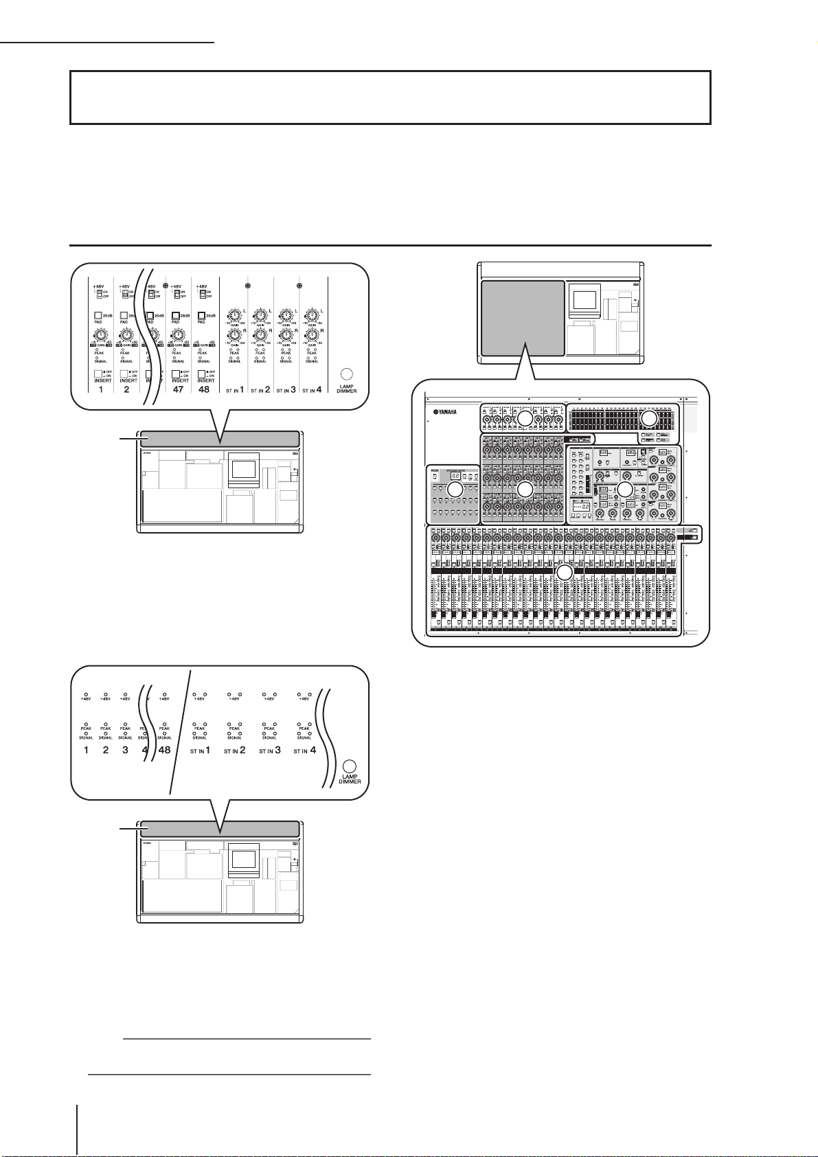
2 Top, front, and rear panels
2 Top, front, and rear panels
This chapter explains the names and functions of each part of the PM5D/DSP5D. Details for each
section of the top panel are explained in subsequent chapters of this operating section; refer to the
appropriate chapter for more information.
Top panel
(PM5D model)
1
A AD IN section (PM5D model)
In this section you can adjust the sensitivity of the analog signals being input from the rear panel INPUT
jacks 1–48 and ST IN jacks 1–4, and switch pad, insert,
and phantom power (+48 V) on/off (➥ p.43).
(PM5D-RH model)
2
B AD IN section (PM5D-RH model)
This area indicates the presence, peak level, and phantom power (+48V) on/off status of the input signal
from rear panel INPUT jacks 1–48 and ST IN jacks 1–
4.
Hint
For the PM5D-RH model, input sensitivity and phantom power
on/off are controlled by operations in the display (➥ p.44).
6 8
4 5
7
3
C INPUT channel strip section
This section controls the principal parameters for input
channels 1–48 (➥ p.45).
D FADER FLIP/ENCODER MODE section
Here you can select the parameters controlled by the
faders/encoders of the INPUT channel strip (
(➥ p.48).
E MIX section
This section controls the on/off status and send level of
the signals sent from input channels to MIX buses, and
adjusts the master level of the MIX channels (➥ p.57).
F MATRIX section
This section controls the send level of the signals sent
from MIX channels to MATRIX buses, and adjusts the
master level of the MATRIX channels (➥ p.63).
G SELECTED CHANNEL section
In this section you can view and control the mix
parameters for the currently selected input channel or
output channel (➥ p.65).
H Meter section
This section contains peak level meters that indicate
the input levels of input channels and the output levels
of output channels and cue monitoring, as selected by
key operations (➥ p.108).
3)
16 PM5D/PM5D-RH V2 / DSP5D Owner’s Manual Operating section
Page 17
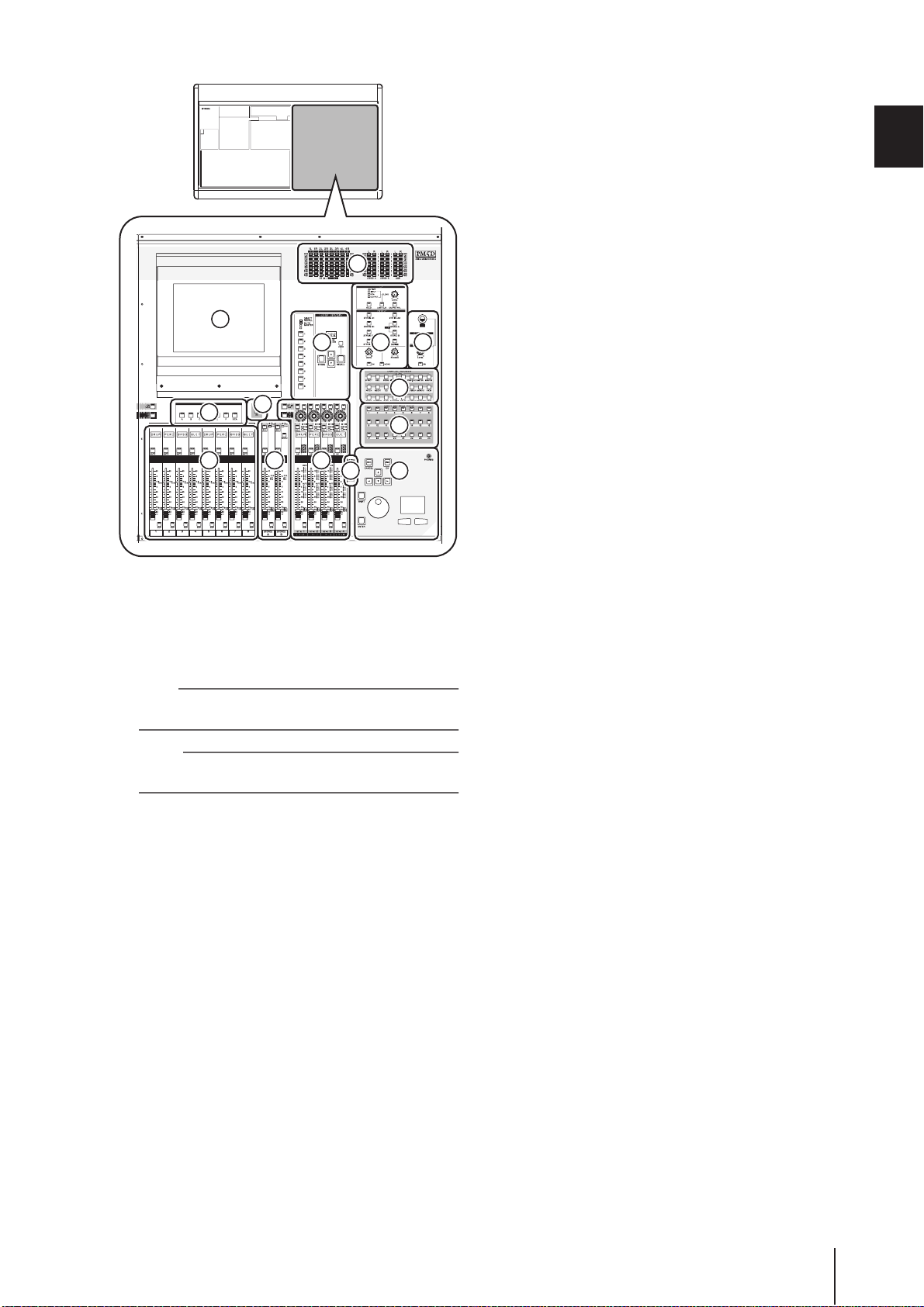
9
N O P
J
R
K M L
8
Q
R
ST
O CUE/MONITOR section
This section selects the monitor source that is output
from the MONITOR OUT jacks, and adjusts the levels. This section also determines the cue point and
monitoring method that will be used when you press a
[CUE] key for a channel (➥ p.99).
P OSCILLATOR/TALKBACK section
This section switches the oscillator or talkback on/off,
and adjusts the talkback level (➥ p.105).
Q DISPLAY ACCESS section
This section selects the functions or screen shown in
the display (➥ p.24).
R USER DEFINED KEYS sections
This section executes the functions that have been
assigned to the User Defined keys [1]–[25] (➥ p.148).
S Data entry section
This section lets you move the pointer (the arrow displayed in the screen) or cursor (the red frame
indicating a selection) in the display and edit the
parameter value (➥ p.24).
T ASSIGN MODE section
This section lets you assign mute groups and DCA
groups for control from the panel (➥ p.81).
2
Top, front, and rear panels
I Display
This display shows the information you need to operate the PM5D, and lets you make system-wide settings
and control mix parameters for input and output
channels (➥ p.23).
Hint
You can adjust the angle of the display by moving the upper
part of the display frame forward or backward.
Note
Before moving the PM5D, you must lower the display all the
way back until it is fastened in place.
J FADER MODE section
Here you can select the combination of channels or
DCA groups that will be controlled by the faders of the
DCA strip section (
K) (➥ p.149).
K DCA strip section
From this section you can control the channels
assigned to DCA groups 1–8 (➥ p.81).
L ST IN/FX RTN (Stereo in / Effect return)
channel strip section
This section controls the principal parameters of ST IN
channels 1–4 or FX RTN channels 1–4 (➥ p.47).
M STEREO strip section
This section controls the principal parameters of the
STEREO A/B channels (➥ p.61).
N SCENE MEMORY section
This section stores/recalls mix parameters as scene
memories (➥ p.88). Mute operations for mute groups
1–8 are also performed in this section (➥ p.83).
PM5D/PM5D-RH V2 / DSP5D Owner’s Manual Operating section 17
Page 18
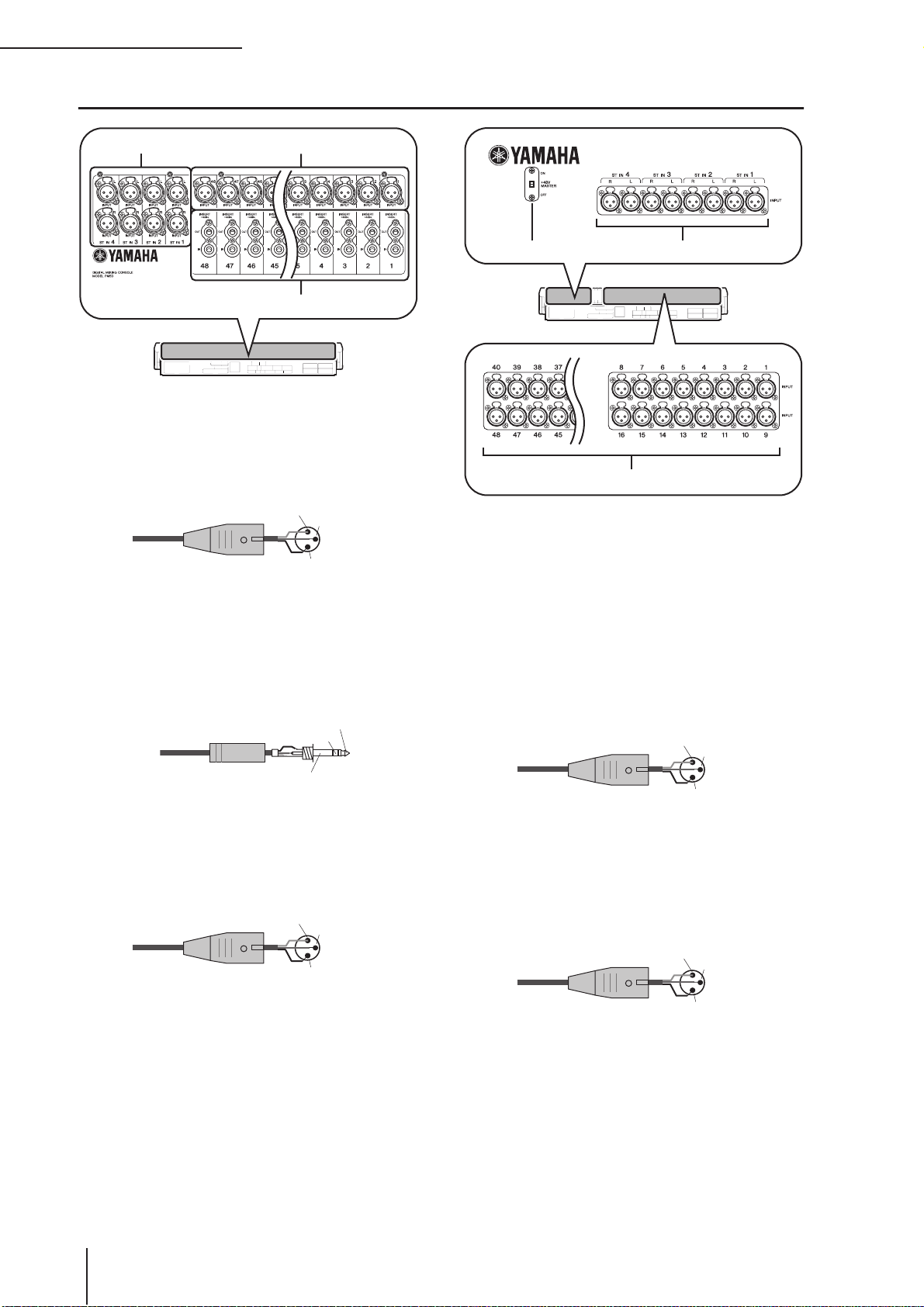
2 Top, front, and rear panels
Rear panel
3 1
(PM5D model)
A INPUT jacks 1–48 (PM5D model)
These are balanced XLR-3-31 type input jacks for
inputting analog audio signals from line level devices
or microphones. Nominal input level is
–60 dBu to +10 dBu.
46
(PM5D-RH model)
2
5
Male XLR plug
1 (ground)
3 (cold)
2 (hot)
B INSERT IN/OUT jacks 1–48 (PM5D model
only)
These are balanced TRS phone type input/output jacks
for inserting external effects or dynamics processors
etc. into INPUT jacks 1–48. Nominal input/output
level is +4 dBu.
1/4" TRS
phone plug
Ring (cold)
Sleeve (ground)
Tip (hot)
C ST IN (Stereo input) jacks 1–4 (PM5D
model)
These are balanced XLR-3-31 type input jacks for
inputting analog audio signals from line level devices.
Nominal input level is –34 dBu to +10 dBu.
Male XLR plug
1 (ground)
3 (cold)
2 (hot)
D +48V MASTER switch (PM5D-RH model
only)
This is the master phantom power (+48V) switch for
INPUT jacks 1–48 and ST IN jacks 1–4. If this switch is
off, the +48V buttons shown in the display are
unavailable.
E INPUT jacks 1–48 (PM5D-RH model)
These are balanced XLR-3-31 type input jacks for
inputting analog audio signals from line level devices
or microphones. Nominal input level is
–62 dBu to +10 dBu.
Male XLR plug
1 (ground)
3 (cold)
2 (hot)
F ST IN (Stereo input) jacks 1–4 (PM5D-RH
model)
These are balanced XLR-3-31 type input jacks for
inputting analog audio signals from line level devices
or microphones. Nominal input level is
–62 dBu to +10 dBu.
Male XLR plug
1 (ground)
3 (cold)
18 PM5D/PM5D-RH V2 / DSP5D Owner’s Manual Operating section
2 (hot)
Page 19
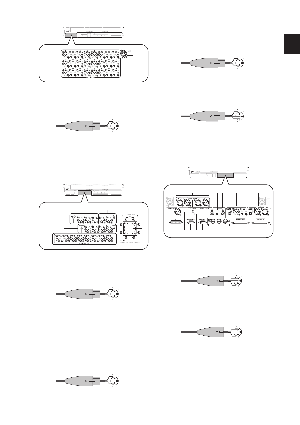
7
G MIX OUT jacks
These are XLR-3-32 (balanced) jacks that output analog signals such as those that are patched from MIX
channels 1–24. Nominal output level is +4 dBu.
Female XLR plug
2 (hot)
3 (cold)
8
K STEREO OUT A/B jacks
These are XLR-3-32 (balanced) jacks that output the
analog signals of the STEREO A/B channels. Nominal
output level is +4 dBu.
Female XLR plug
2 (hot)
1 (ground)
3 (cold)
L MATRIX OUT jacks
These are XLR-3-32 (balanced) jacks that output the
analog signals of MATRIX channels 1–8. Nominal output level is +4 dBu.
Female XLR plug
2 (hot)
1 (ground)
3 (cold)
2
Top, front, and rear panels
1 (ground)
H LAMP connector
This is a four-pin female XLR output jack for supplying power to a gooseneck lamp. (These jacks are
provided at three locations). The location of these jacks
differs between the PM5D model and the PM5D-RH
model.
RLRL
C
RLRL
87654321
I MONITOR OUT jacks
These are XLR-3-32 (balanced) jacks that output the
monitor signal selected in the MONITOR section of
the top panel. Nominal output level is +4 dBu.
Female XLR plug
2 (hot)
3 (cold)
M DC POWER INPUT connector
This is a connector for connecting the PW800W power
supply. Use the dedicated cable included with the
PM5D to make the connection.
N X YVUT
R
MJ9KL
IN
SMPTE
R
L
USB
L
OUT IN
THRU OUT IN
75
ON OFF
21
3
COAXIAL COAXIALAES/EBU AES/EBU AES/EBU AES/EBU
3
21
Q R S Z aWPO
N 2TR IN ANALOG jacks 1/2
These are XLR-3-31 (balanced) jacks that input stereo
analog signals from an external source. Nominal input
level is +4 dBu.
Male XLR plug
1 (ground)
3 (cold)
2 (hot)
1 (ground)
Note
Although the various output jacks and 2TR IN ANALOG jacks
have a nominal input/output level of +4 dBu (maximum level is
+24 dBu), an internal switch allows this to be changed to
–2 dBu (maximum level +18 dBu) if necessary. For details,
contact your Yamaha dealer.
J CUE OUT jacks
These are XLR-3-32 (balanced) jacks that output the
cue monitor signal from the channel selected by its
[CUE] key. Nominal output level is +4 dBu.
Female XLR plug
2 (hot)
1 (ground)
3 (cold)
PM5D/PM5D-RH V2 / DSP5D Owner’s Manual Operating section 19
O TIME CODE INPUT jack
This is an XLR-3-31 (balanced) jack that receives
SMPTE time code (LTC) from an external source.
Male XLR plug
1 (ground)
3 (cold)
2 (hot)
P TO HOST connector
This is a USB (type B) connector that allows communication with a computer.
Note
PM5D Editor and the USB-MIDI driver required for connection
with your computer can be downloaded from the Yamaha
website listed below.
http://www.yamahaproaudio.com/
Page 20
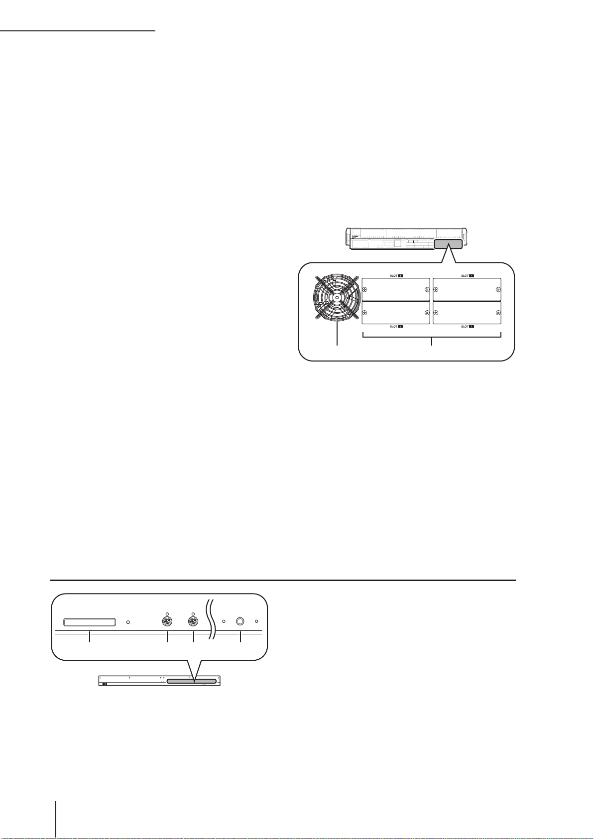
2 Top, front, and rear panels
Q GPI connector
This is a D-sub 25-pin female connector that allows
communication with a GPI-equipped external device.
R RS422 REMOTE connector
This is a D-sub 9-pin female connector for remotely
controlling an external device that supports the RS422
protocol.
S HA REMOTE connector
This is a D-sub 9-pin male connector for remotely controlling an external head amp device (e.g., Yamaha
AD8HR or AD824) that supports a special protocol.
T WORD CLOCK IN connector
This is a BNC connector for supplying a word clock
from an external device to the PM5D.
U 75Ω ON/OFF switch
This switch terminates the word clock connection.
Normally you will leave this ON. If a device made by
another manufacturer is connected and word clock
cannot be received correctly, try turning this OFF.
V WORD CLOCK OUT connector
This is a BNC connector for supplying a word clock
from the PM5D to an external device.
W MIDI IN/THRU/OUT connectors
These connectors are used to transmit and receive
MIDI messages to and from external MIDI devices.
The MIDI IN connector receives messages from an
external device, and the MIDI OUT connector transmits messages from the PM5D. Messages received at
the MIDI IN connector are retransmitted without
change from the MIDI THRU connector.
X 2TR OUT DIGITAL (2 track out digital) jacks
1–3
These jacks digitally output the signals of the STEREO
A/B channels. Two types are provided; AES/EBU
(XLR-3-32) jacks (1/2) which output AES/EBU format
signals, and a COAXIAL (RCA phono) jack (3) which
outputs consumer format signals (IEC60958).
Y 2TR IN DIGITAL (2 track in digital) jacks 1–3
These jacks input digital audio from external devices
such as CD players. Two types are provided; AES/EBU
(XLR-3-31) jacks (1/2) which receive AES/EBU format
signals, and a COAXIAL (RCA phono) jack (3) which
receives consumer format signals (IEC60958).
Z CASCADE OUT connector
This is a D-sub half-pitch 68-pin female connector that
can be connected to another PM5D, DSP5D, DCU5D
or DME64N for transmission/reception of control signals and transmission of audio signals.
a CASCADE IN connector
This is a D-sub half-pitch 68-pin female connector that
can be connected to another PM5D, DSP5D or
DCU5D for transmission/reception of control signals
and reception of audio signals.
cb
b Cooling fan vent
This is the vent for the cooling fans inside the console
(two locations). When placing the unit, take care that
this vent is not obstructed.
c SLOT 1–4
These slots allow separately sold mini-YGDAI I/O
cards to be installed to expand the input/output ports.
Front panel
A MEMORY CARD slot
A memory card inserted in this slot can be used to
MEMORY CARD
MOUSE
PHONES
56
56
43
43
12
12
KEYBOARD
1 2 3 4
KEYBOARD
MOUSE
MEMORY CARD
PHONES
20 PM5D/PM5D-RH V2 / DSP5D Owner’s Manual Operating section
save/load scene memories or library data. You can use
PCMCIA Type II flash ATA cards, or CompactFlash
cards inserted into a PC card adaptor.
B MOUSE connector
A PS/2 mouse can be connected to this connector and
used to perform operations in the display.
C KEYBOARD connector
A PS/2 keyboard can be connected to this connector
and used to input text or perform operations in the
display.
D PHONES (Headphone) jack
This headphone jack lets you monitor the MONITOR
OUT or CUE signals.
Page 21
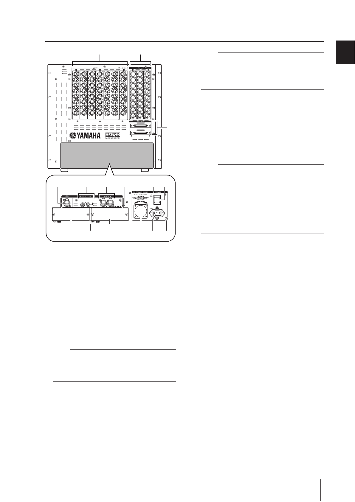
1 2
A
B
C
D
E
F
G
➥
H
I
J
K
L
M
DSP5D front panel
CASCADE IN
75Ω
OUT OUT
5 64
OUT OUT
TERMINATED
ININ
TERMINATED
OUT
IN
TXRX TX RX
7 KJ
75Ω
ININ
OUT
IN
TX RX TX RX
8 9 L M
INPUT jacks 1–48 / ST IN (stereo input)
jacks 1–4
These are balanced XLR-3-31 type input jacks for
inputting analog audio signals from line level devices
or microphones. The nominal input level is –62 dBu to
+10 dBu. A resettable head amp is provided on all
jacks, and head amp settings can be stored in scene
memory.
OMNI OUT jacks 1–24
These are XLR-3-32 (balanced) jacks for outputting
analog audio signals. These are used mainly for outputting the MIX/MATRIX/STEREO A/B channel signals.
The nominal output level is +4 dBu.
Note
The nominal output level of OMNI OUT jacks 1–24 is +4 dBu
(maximum level is +24 dBu), but if necessary, this can be
changed to –2 dBu (maximum level +18 dBu) by setting an
internal switch (a fee will be charged). For details, please contact your Yamaha dealer.
CASCADE IN/OUT connectors
These are D-sub half-pitch 68-pin female connectors to
allow connection of the DSP5D, PM5D, DCU5D, and
DME64N so that audio signals and control signals can
be transmitted and received.
NETWORK connector
This connector allows the DSP5D to be connected to a
Windows computer via a CAT5 Ethernet cable.
This is used mainly when remotely controlling or editing the DSP5D from the dedicated “DSP5D Editor”
application software.
3
Note
• You should use a CAT5 STP (Shielded Twisted Pair) cable
to prevent electromagnetic interference.
• DSP5D Editor and the DME-N Network driver required for
connection with your computer can be downloaded from the
Yamaha website listed below.
http://www.yamahaproaudio.com/
WORD CLOCK IN/OUT connectors
These are BNC connectors used to input and output
word clock signals from and to an external device. The
input connector is terminated with 75 ohms.
CASCADE IN/OUT connectors
These are RJ-45 connectors that can be connected via a
CAT5 Ethernet cable to a DSP5D or DCU5D so that
audio signals and control signals can be transmitted
and received.
Note
• As connectors, use RJ-45 connectors that are compatible
with Neutrik’s EtherCon
• As cables, you should use CAT5 STP cables (shielded
twisted pair cables) to prevent electromagnetic interference.
• To prevent electromagnetic interference, use conductive
tape etc. to firmly fasten the metal portion of the connector to
the shield of the cable.
• These connectors use EtherSound technology, but are only
for use with the PM5D system; they cannot be connected to
other EtherSound equipment. For details on the length of
cables that can be used, refer to the following website.
http://www.ethersound.com/technology/compatibility.php
®
.
IN/OUT [TX]/[RX] LED
When signals are transmitted (TX) or received (RX) via
the [CASCADE IN]/[CASCADE OUT] connectors, the
corresponding LED will light.
When you use the rear panel mode switch to set the
machine ID, the number of LEDs corresponding to the
machine ID number will light for five seconds
p.153).
(
SLOT 1–2
The input/output ports can be expanded by installing
separately sold mini-YGDAI I/O cards in these slots.
DC POWER INPUT connector
A separately sold PW800W power supply can be connected here as an external backup power supply. Use a
power supply link cable (PSL360) to make this
connection.
POWER LED
This will light if power is being supplied to the DSP5D.
POWER switch
This switch turns the power on/off.
AC IN connector
Use the included power cable to supply power to this
connector.
Grounding screw
For safe operation, be sure that the DSP5D is correctly
grounded. The included power cable has a three-pin
plug, and if the AC outlet is grounded, the DSP5D will
be grounded appropriately. If the AC outlet you’re
using is not grounded, you must be sure to connect
this screw to a valid electrical ground. Correct grounding will effectively eliminate noises such as hum and
interference.
2
Top, front, and rear panels
PM5D/PM5D-RH V2 / DSP5D Owner’s Manual
Operating section
21
Page 22
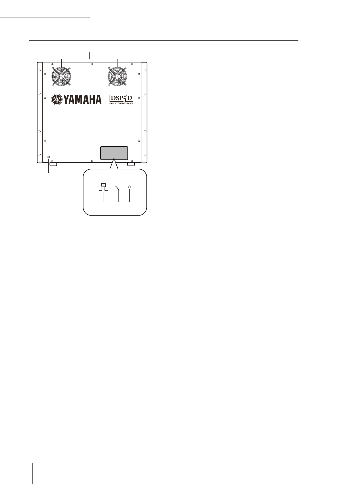
2 Top, front, and rear panels
1
DSP5D rear panel
5
FAN
HIGH LOW
FAN
HIGH LOW
2 3 4
POWER
POWER
A Cooling fan vents
These are the vents for the DSP5D’s internal cooling
fans (two locations). When placing the unit, take care
that these vents are not obstructed.
B FAN switch
This switches the rotational speed of the DSP5D’s
internal cooling fans between HIGH and LOW.
For normal use, set this to LOW. However if the
DSP5D is in a location of high temperature or is outside in direct sunlight, set this to HIGH. You should
also set this to HIGH if you feel that the panel is
warmer than usual.
C Mode switch
This switch is used when initializing the settings of
internal memory, when updating the firmware in the
future, and when setting the machine ID number.
D POWER LED
This will light if power is being supplied to the DSP5D.
E Grounding screw
For safe operation, be sure that the DSP5D is correctly
grounded. The included power cable has a three-pin
plug, and if the AC outlet is grounded, the DSP5D will
be grounded appropriately. If the AC outlet you’re
using is not grounded, you must be sure to connect
this screw to a valid electrical ground. Correct grounding will effectively eliminate noises such as hum and
interference.
22 PM5D/PM5D-RH V2 / DSP5D Owner’s Manual Operating section
Page 23
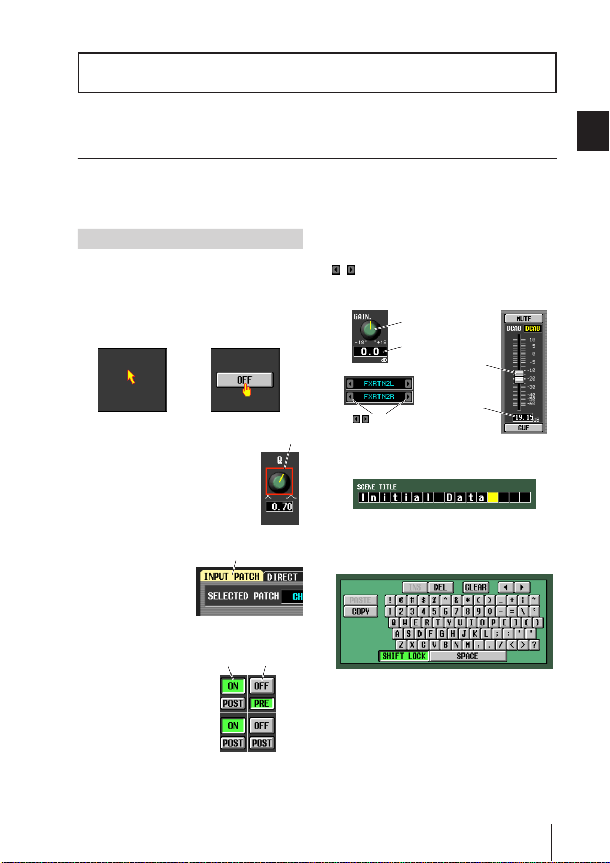
3 Basic operation on the PM5D
This chapter explains the various types of user interface used to operate the PM5D.
About the various types of user interface
Basic parameters such as mixing and editing the sound of each channel can be controlled by the faders and encoders of the top
panel. However to make more detailed settings, you will need to access the appropriate “function” and edit the parameter values in the display. The section below explains the various user interface components shown in the display, and how to use
them.
3
User interface in the display
The user interface in the PM5D’s display uses the following components.
❏ Pointer
The arrow shown in the display is called the “pointer.” Use
the pointer to select the parameter you want to control
next.
❏ Cursor
The red frame shown in the display is called
the “cursor.” If the cursor encloses a parameter on the screen, that parameter is selected
for operation.
Cursor
❏ Knobs/Faders/Boxes
Knobs/faders in the display are used to edit parameter values. The current value is shown in the box. Boxes for which
/ buttons are displayed at left and right allow you to
edit the parameter by using these buttons. (If editing is not
possible, the buttons will be gray.)
Knob
Box
Fader
Box
/ buttons for
editing the value
If you want to assign a name to a channel or scene, input
characters, numerals, and symbols into the box.
Basic operation on the PM5D
❏ Tabs
The screen names shown in
the upper left of the display
are called “tabs.” Tabs are
used to switch between
screens within the same
function.
❏ Buttons
Buttons in the display are
used to switch parameters
on/off or to select one of
multiple choices. Buttons
that are currently on are displayed in green (some
buttons are displayed in red
or blue); buttons that are
turned off are displayed in
gray.
Ta b
Buttons turned
on (green)
❏ Character palette
This is a “virtual” keyboard used to input characters,
numerals, and symbols into a text input box.
Buttons turned
off (gray)
PM5D/PM5D-RH V2 / DSP5D Owner’s Manual Operating section 23
Page 24
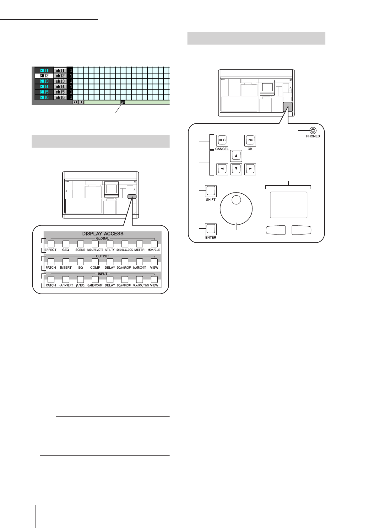
3 Basic operation on the PM5D
❏ Scroll bar
If the displayed items are too numerous to fit into a single
screen, you can use the scroll bar to view the portion that is
not currently displayed.
Scroll bar
DISPLAY ACCESS section
The DISPLAY ACCESS section contains keys that access
the desired function or screen in the display.
Data Entry section
Controllers used to edit settings and values in the display
are gathered into the data entry section.
7
1
2
6
3
1
2
3
A Global functions
These keys access functions that affect the entire
PM5D.
B Output functions
These keys access functions that are related to output
channels.
C Input functions
These keys access functions that are related to input
channels.
When you press the key for the desired function, the screen
for that function will appear in the display. By repeatedly
pressing a key you can cycle through the screens included
in that function.
Hint
If you hold down the [SHIFT] key and press a key in the DISPLAY ACCESS section, the screens included in that function
will appear in the reverse order (Page Back function). You can
also use the Page Back function by holding down a key in the
DISPLAY ACCESS section. If you rapidly press a key twice,
you will return to the first screen in that function.
4
5
A [DEC/CANCEL]/[INC/OK] keys
Use these keys to increase or decrease the value of the
parameter where the cursor is located. If the PM5D has
displayed a window asking you to confirm an operation such as recall or store, these buttons can be used
instead of the CANCEL button and OK button shown
in the window.
B CURSOR [√]/[®]/[π]/[†] keys
These keys are used to move the cursor to the desired
parameter.
C [SHIFT] key
This key can be used in conjunction with the CURSOR [√]/[®]/[π]/[†] keys to move the cursor
rapidly, or in conjunction with the [DATA] encoder or
[DEC]/[INC] keys to change the parameter value
rapidly.
If you hold down the [SHIFT] key and press the
[ENTER] key, the JOB SELECT window will appear,
allowing you to set multiple parameters in a single
operation. (When you move the cursor to a parameter
for which there is a JOB SELECT window, an indication of “Job Select = [SHIFT] + [ENTER]” will
appear.)
D [ENTER] key
Use this key to switch a button at the cursor location
on/off, or to open a window.
E [DATA] encoder
Use this to increase or decrease the value of the parameter where the cursor is located. The parameter value
will change more rapidly if you turn the [DATA]
encoder while holding down the [SHIFT] key.
24 PM5D/PM5D-RH V2 / DSP5D Owner’s Manual Operating section
Page 25
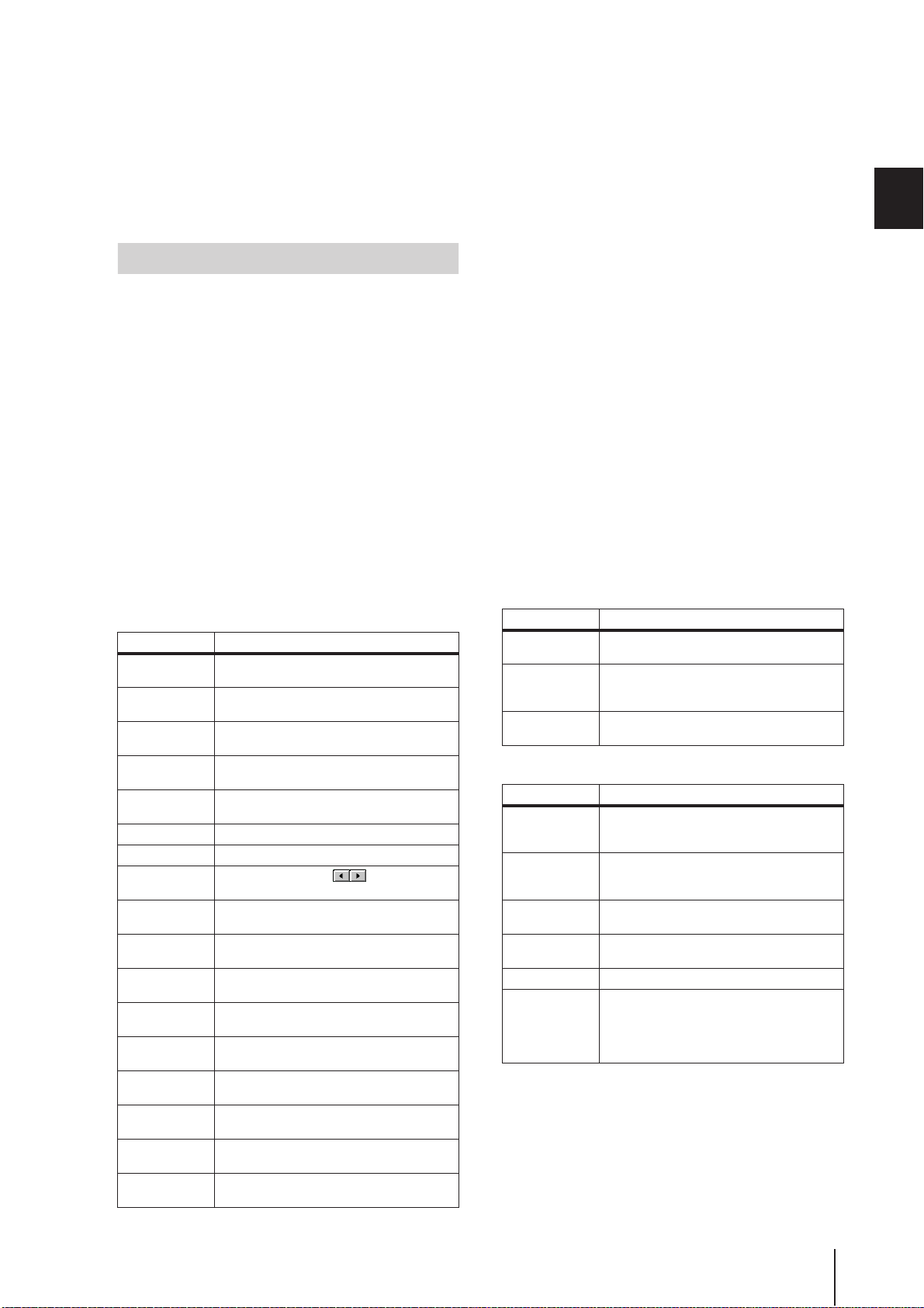
F Track pad and left/right buttons
These are used to move the pointer or select the desired
parameter. To adjust a knob-type parameter in the display, hold down the left button or right track pad
button while you operate the track pad.
G PHONES (Headphone) jack
This is a stereo phone jack for connecting a set of
headphones.
External user interface
If desired, you can add the following external user interface components.
❏ Mouse
A PS/2 compatible mouse can be connected to the MOUSE
connector located on the front panel of the PM5D and
used in the same way as the track pad.
3
❏ Keyboard
A PS/2 compatible keyboard can be connected to the KEYBOARD connector located on the front panel of the PM5D
and used in the same way as the character palette in the
display to input characters, numerals, and symbols. The
numeric key pad of the keyboard can be used to input
numerical values or to recall scenes.
Each key (or combination of keys) has the following
function.
Full keyboard
Key Function
<PageUp>
<PageDown>
<←>, <→>,
<↑>, <↓>
<Alt> +
<PageUp>
<Alt> +
<PageDown>
<Enter> Same function as the [ENTER] key
<Shift> Same function as the [SHIFT] key
<Ctrl> + <←>,
<Ctrl> + <→>
<Ctrl> + <x>
<Ctrl> + <c>
<Ctrl> + <v>
<Insert>
<Delete>
<Home>
<End>
<BackSpace>
<Tab>
Same function as the [INS/OK] key of the Data
Entry section
Same function as the [DEC/CANCEL] key of
the Data Entry section
Same function as the CURSOR [√]/[®]/[π]/
[†] keys
Same function as moving the [DATA] encoder
clockwise
Same function as moving the [DATA] encoder
counterclockwise
Same function as the buttons of the
character palette
Copies the text string in the box and clears the
copy-source character string (Cut)
Same function as the COPY button of the
character palette
Same function as the PASTE button of the
character palette
Same function as the INS button of the character palette
Same function as the DEL button of the character palette
Moves the input location in the box to the
beginning
Moves the input location in the box to after the
last-input character
Deletes the preceding character that was
input in the box (Backspace)
Switches to the next screen within the same
function
Key Function
<Shift> + <Tab>
<Esc>
<Alt> +
<0>–<9>
Switches to the previous screen within the
same function
Accesses the function menu (if the function
menu is already displayed, recalls the last-displayed screen)
Switch screens within the same function
Numeric key pad
Key Function
<0>–<9>
<.>
<+>
<->
</>, <*> Not used
<Enter>
Input a scene number (if the PREFERENCE 1
screen item USE NUMERIC-KEYPAD is on),
input numerical values (if off)
Returns the scene selection number to the
number of the scene that was last recalled or
stored
Same function as the [π] key of the SCENE
MEMORY section
Same function as the [†] key of the SCENE
MEMORY section
Same function as the [RECALL] key of the
SCENE MEMORY section (if the PREFERENCE 1 screen item USE NUMERIC-KEYPAD is on), same function as the [ENTER] key
(when off)
Basic operation on the PM5D
PM5D/PM5D-RH V2 / DSP5D Owner’s Manual Operating section 25
Page 26
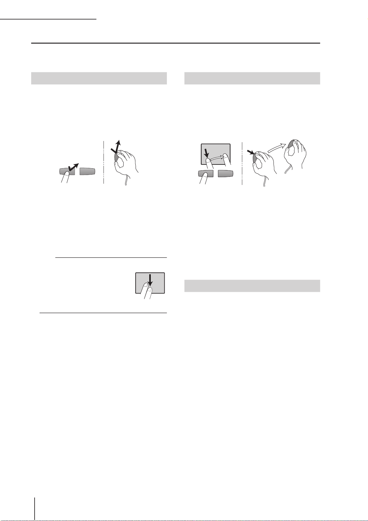
3 Basic operation on the PM5D
Basic operation
This section explains the basic procedures you can perform in the PM5D’s display. In general, you will perform operations in
the PM5D’s display by combining the operations described here.
Click
Moving the pointer to a specific parameter in the screen
and pressing the left/right track pad button (or the left/
right mouse button) is called “clicking.” Clicking is mainly
used to turn an on-screen button on/off, to move the cursor, or to make fine adjustments to a value.
• Track pad • Mouse
Click
Click
Using the CURSOR [√]/[®]/[π]/[†] keys of the data
entry section to move the cursor to a desired parameter
and then pressing the [ENTER] key is equivalent to clicking. If you are using a PS/2 keyboard, you can perform the
same action using the arrow keys and the <Enter> key.
Subsequently in this manual, this operation will simply be
called “clicking.”
Hint
When using the track pad, you can
move the pointer to the desired parameter and then tap the track pad to
obtain the same result as if you
pressed the left button. (This is called
the Tapping function.) If you want to
use the tapping function, you must
enable it in the PREFERENCE 2
screen (UTILITY function) (➥ p.206).
• Track pad
Tapping
Drag
Moving the pointer to a specific parameter in the screen
and then holding down the left/right track pad (or mouse)
button while moving up/down/left/right is called “dragging.” Dragging is used mainly to adjust the value of a
knob or fader.
• Track pad • Mouse
Drag
While pressing
Drag
Using the CURSOR [√]/[®]/[π]/[†] keys of the data
entry section to move the cursor to a desired parameter
and then turning the [DATA ] encoder (or pressing the
[DEC/CANCEL]/[INC/OK] keys) is equivalent to dragging. If you are using a PS/2 keyboard, you can perform the
same action using the arrow keys and the <PageUp>/
<PageDown> keys (or keys that have the same function).
Subsequently in this manual, this operation will simply be
called “dragging.”
Drag and drop
Moving the mouse pointer to a specific parameter in the
screen, dragging to another location in the screen, and then
releasing your finger is called “dragging and dropping.”
Dragging and dropping is used to copy EQ or compressor
settings to another channel. Dragging and dropping cannot be performed using the CURSOR keys or keyboard.
Subsequently in this manual, this operation will be called
“dragging and dropping.”
26 PM5D/PM5D-RH V2 / DSP5D Owner’s Manual Operating section
Page 27
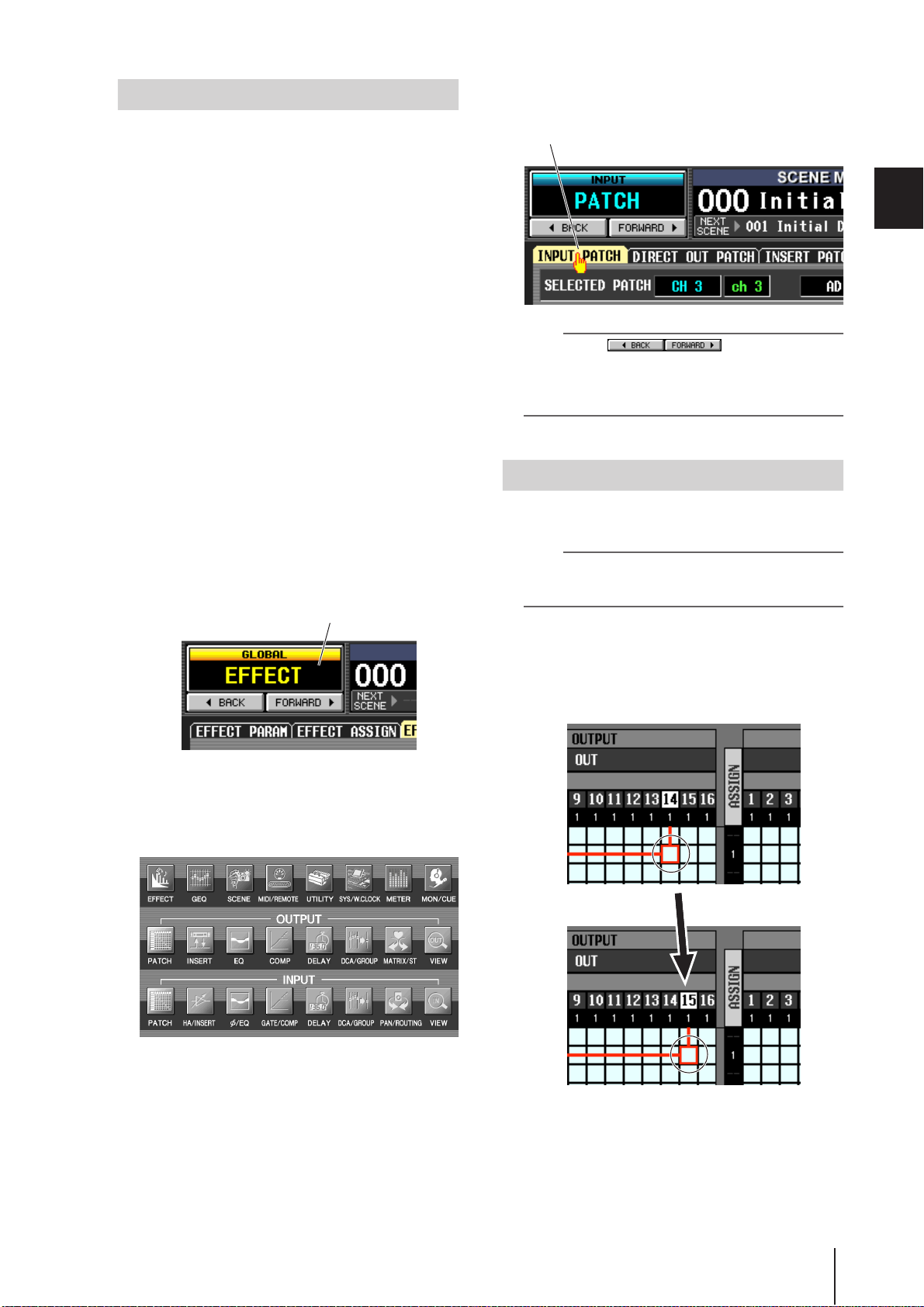
Accessing a desired screen
A desired function/screen can be accessed in the display
using either of the following two methods.
❏ Using the keys of the DISPLAY ACCESS
section
From the keys of the DISPLAY ACCESS section,
1
press the key corresponding to the desired
function.
The most recently operated screen for that function
will appear.
If you want to switch to another screen within
2
that function, press the same key you pressed
in step 1.
If you repeatedly press a key in the DISPLAY ACCESS
section, or hold down the [SHIFT] key of the data
entry section and press the same key as in step 1, you
will return to the preceding screen of the same
function.
❏ Using buttons within the display
In any screen, click the function name area
1
located in the upper left of the screen.
When you click the function name area, the function
menu screen will appear. This screen is the starting
point from which you can access the desired screen via
operations in the display.
Click the function name area
Click a tab in the screen to select the desired
3
screen.
Click a tab
Hint
By clicking the buttons located below
the function name area you can switch backward through the
screens that had been previously displayed for at least two
seconds (not including the function menu). Up to the eight
most recent screens are remembered.
Moving the cursor
To select a parameter, use the data entry section’s controllers or a PS/2 keyboard to move the cursor (the red frame).
Hint
If you are using a mouse or the track pad, the cursor will move
when you click on the button or knob of the desired
parameter.
Use the CURSOR [√]/[®]/[π]/[†] keys to
1
move the cursor.
The cursor in the display will move in the direction of
the key you pressed. However, it will not move if there
is no parameter in the direction of that key.
3
Basic operation on the PM5D
In the function menu screen, click the button
2
corresponding to the desired function.
The most recently operated screen for that function
will appear.
Move to the adjacent grid
PM5D/PM5D-RH V2 / DSP5D Owner’s Manual Operating section 27
Page 28
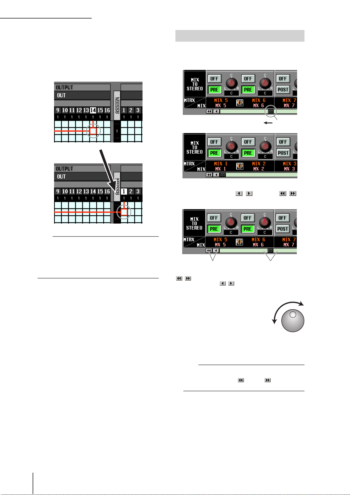
3 Basic operation on the PM5D
To move quickly to the outer edge of the cur-
2
rent window or to a different window, hold
down the [SHIFT] key and use the CURSOR
[√]/[®]/[π]/[†] keys.
You will move from the scroll window in which the
cursor is currently located, in the direction of the key
you pressed.
Scrolling the screen
A scroll bar is displayed if there are more items than can be
shown in a single screen. To scroll the screen, drag the box
shown in the bar.
[SHIFT] key
+
CURSOR [®] key
Hint
If the cursor is located on a grid such as in a PATCH screen,
turning the [DATA] encoder clockwise will move the cursor
toward the right, and turning it counterclockwise will move the
cursor toward the left. If you are holding down the [SHIFT]
key, turning the [DATA] encoder clockwise will move the cursor downward, and turning it counterclockwise will move the
cursor upward.
➠
Drag
You can also scroll the screen by clicking the vacant portion of the scroll bar or the / buttons or /
buttons located at the ends of the scroll bar.
Click these buttons to move the
scroll bar box step-wise in the
direction indicated. Clicking the
/ buttons will move in larger
steps than clicking the /
buttons.
Click in these areas to
make the scroll bar box
move by a large step in the
corresponding direction;
the screen will scroll
accordingly.
If you move the cursor to the scroll bar
and press the [DEC/CANCEL] key or
turn the [DATA] encoder counterclockwise, the screen will scroll toward the left
(or upward, in the case of vertical scrolling). If you press the [INC/OK] key or
turn the [DATA] encoder clockwise, the screen will scroll
toward the right (or downward, in the case of vertical
scrolling).
Hint
If the cursor is located at the scroll bar box, holding down the
[SHIFT] key and turning the [DATA] encoder will have the
same result as clicking the button or button, depending on the direction in which you turn the encoder.
28 PM5D/PM5D-RH V2 / DSP5D Owner’s Manual Operating section
Page 29
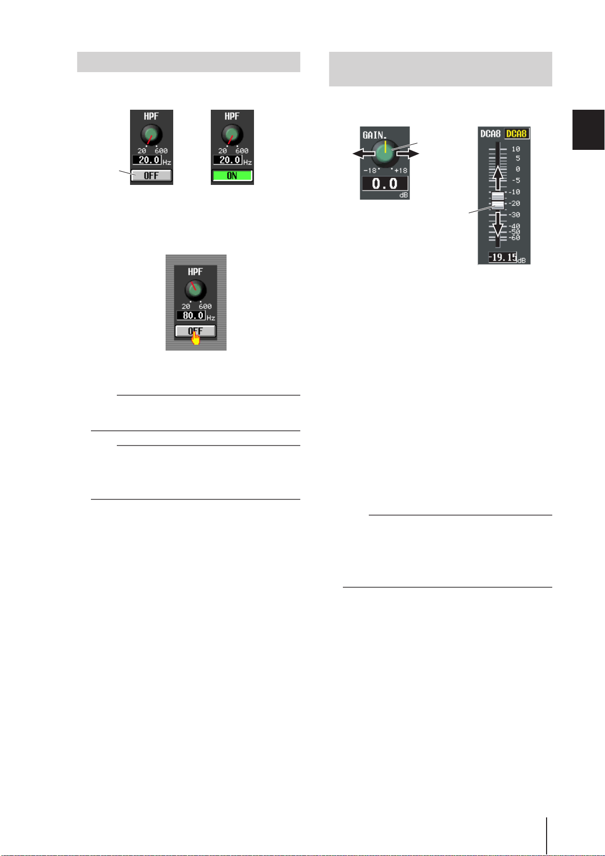
Operating the buttons
Buttons in the display are used to switch parameters on/off
or to select one of multiple choices.
Adjusting the setting of a knob or fader
Knobs and faders in the display are used to adjust the value
of specific parameters.
Click
Off On
Move the pointer to the desired button, and
1
use the left/right buttons of the track pad (or
➠
mouse) to click the button.
The button will be switched on/off (or the corresponding button will be selected).
Hint
You can use the CURSOR [√]/[®]/[π]/[†] keys and the
[ENTER] key (or the arrow keys and <Enter> key of a PS/2
keyboard) to perform the equivalent operation.
Hint
When using the track pad, you can also click by tapping the
track pad if you have enabled tapping in the PREFERENCE 2
screen (UTILITY function
be the same as if you pressed the left button of the track pad
(or mouse).
➥
p.206). In this case, the result will
Adjust the
knob value
Adjust the
fader value
Move the pointer to the desired knob/fader,
1
and use the left/right buttons of the track pad
(or mouse) to click the knob/fader.
The cursor will move to that location.
To increase or decrease the value in steps of 1,
2
click the right button or left button of the
track pad (or mouse).
Clicking the right button will raise the value by one
step, and clicking the left button will lower the value by
one step.
To raise or lower the value continuously, use
3
the track pad (or mouse) to drag the knob/
fader.
The value will change as you drag the knob or fader
left/right or up/down. For a parameter whose knob has
a wide range of adjustment, holding down the right
button of the track pad (or mouse) as you drag will
produce a larger range of change than when using the
left button.
Hint
You can also adjust the value by using the [DEC/CANCEL]/
[INC/OK] keys, the [DATA] encoder, or the <PageUp>/<PageDown> keys of a PS/2 keyboard. When adjusting a parameter
that has a wide range of adjustment, you can increase the rate
of change by holding down the [SHIFT] key while you press
the [DEC/CANCEL]/[INC/OK] keys (or turn the [DATA]
encoder).
3
Basic operation on the PM5D
PM5D/PM5D-RH V2 / DSP5D Owner’s Manual Operating section 29
Page 30
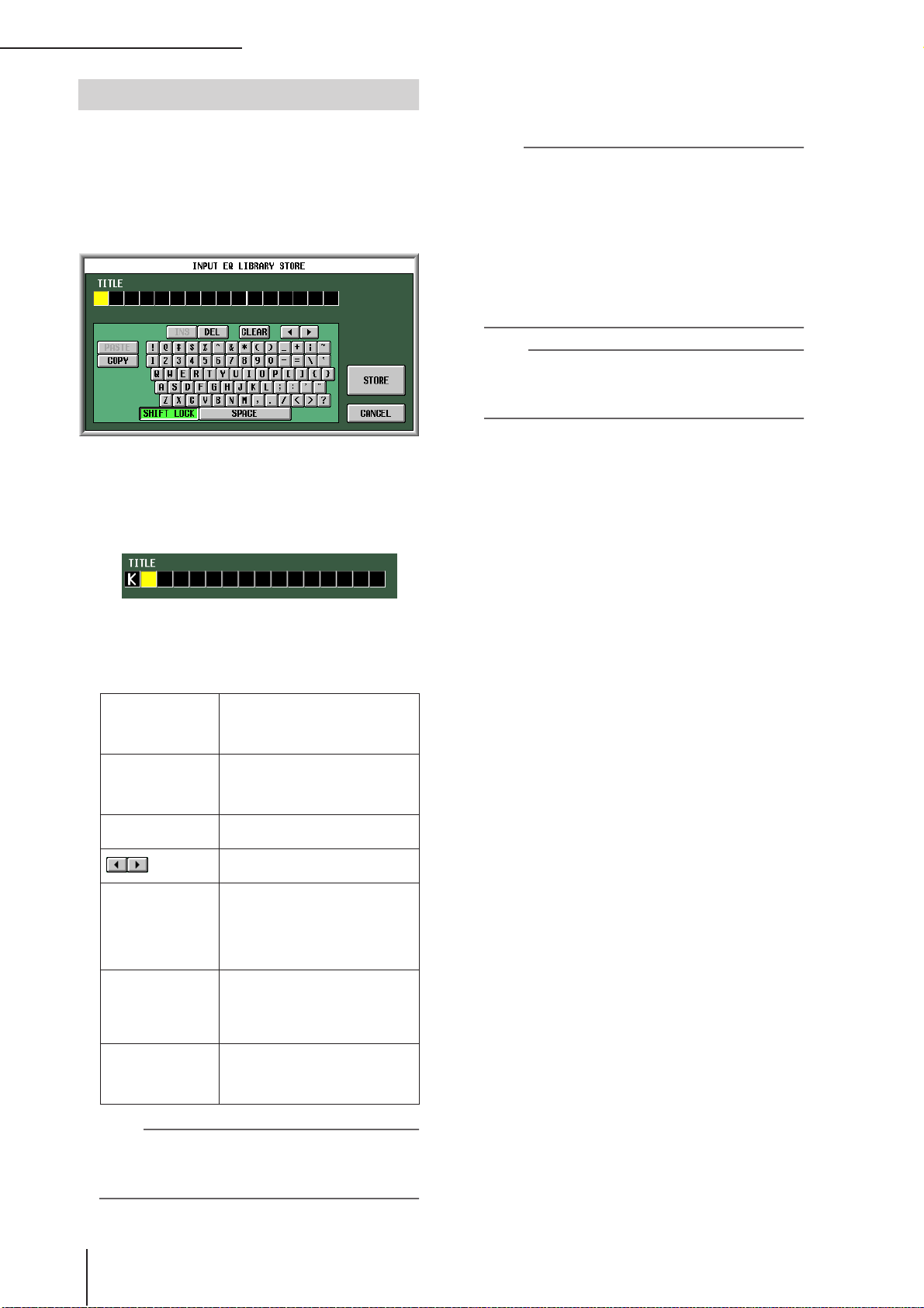
3 Basic operation on the PM5D
Assigning a name
On the PM5D you can assign a four-character name to
each input channel or DCA group, and assign a title to
scene and library data when saving it.
For example, the screen shown below is the LIBRARY
STORE window that appears when you assign a name to
the INPUT EQ library. To input characters in this screen,
use the following procedure.
Use the character palette (or a PS/2 key-
1
board) to input a character.
When you click the character palette, a character will
be input in the box, and the highlighted area will move
to the right.
When you have finished inputting the name,
3
click the STORE button.
The name you input will be stored.
Hint
• In general, the same procedure applies in screens where
you enter names for scenes or other library items.
• If a PS/2 keyboard is connected, you can use it to enter
characters.
• If you move the cursor to the text input box and press the
[ENTER] key (or click), the input position will move to that
point. If the cursor is located at the text input box, you can
step through the available characters by turning the [DATA]
encoder. If the cursor is located elsewhere, turning the
[DATA] encoder will move the selected position. The [INC]/
[DEC] keys move the selected position regardless of where
the cursor is located.
Note
The number of characters that can be input will depend on the
type of data (scene/library) you are saving. You cannot input
more than the specified number of characters, or move the
highlighted area beyond that range.
Input the subsequent characters in the same
2
way.
When inputting characters, you can use the following
buttons in the character palette.
Inserts a space (blank) at the high-
INS button
DEL button
CLEAR button
buttons
PASTE button
COPY button
CAPS LOCK button
lighted position. Pressing the
<Insert> key of a PS/2 keyboard will
produce the same result.
Deletes the character at the highlighted position. Pressing the
<Delete> key of a PS/2 keyboard will
produce the same result.
Deletes all characters that have been
input in the text input box.
Move the highlighted area to left or
right.
Pastes the character string that was
copied to buffer memory by the
COPY button. Holding down the
<Ctrl> key and pressing the <V> key
of a PS/2 keyboard will produce the
same result.
Copies the character string in the box
to a temporary buffer memory. Holding down the <Ctrl> key and pressing
the <C> key of a PS/2 keyboard will
produce the same result.
Switches between uppercase and
lowercase alphabetical characters.
Uppercase characters can be input
while this button is on.
Note
Copy/paste operations are not possible in some screens.
There are also cases in which the paste operation cannot be
performed due to the type of character string copied to the
buffer memory.
30 PM5D/PM5D-RH V2 / DSP5D Owner’s Manual Operating section
Page 31

4 Connections and setup
This chapter describes examples of expanded systems using the DSP5D, audio input/output connections, and the setup that will be necessary when starting up the PM5D/DSP5D for the first time.
Examples of systems expanded with the DSP5D
• In order to use “cascade connections” for expansion, you must first specify the machine ID (➥ p.153) and make cascade
connection settings (➥ p.154). If the PM5D and DSP5D are cascade-connected, you’ll be able to select the PM5D/DSP5D
that will be the target of control from the PM5D’s panel (➥ p.40).
4
Example of simple input expansion (PM5D + one DSP5D unit)
• This system expands the number of input channels to
96 monaural + 8 stereo.
• To make cascade connections, use a D-sub half-pitch
68-pin cable to connect the CASCADE IN connector to
the OUT connector of each respective PM5D and
DSP5D unit.
FoH
PM5D
CASCADE
OUTINOUTIN
CASCADE IN
DSP5D
PM5D + remotely connected input expansion (PM5D + DCU5D + two DSP5D units)
• The connection between the PM5D located at FoH and
the DSP5D located on the stage is routed through the
DCU5D, via Ethernet CAT5 cable and the CASCADE
IN and OUT connectors.
• By using two DSP5D units, the number of input channels is expanded to 144 monaural + 12 stereo.
• To make cascade connections between the PM5D and
DCU5D, use D-sub half-pitch 68-pin cables to connect the CASCADE IN connectors to the OUT
connectors of each respective unit.
• Connections between the two DSP5D units are made
using an Ethernet CAT5 cable and a D-sub half-pitch
68-pin cable, each connected from CASCADE IN to
OUT of the two units.
Stage
IN
DSP5D DSP5D
Ethernet CAT5
OUT
CASCADE IN CASCADE IN
IN
CASCADE
IN
OUT
Connections and setup
Ethernet
CAT5
OUT
DCU5D
FoH
IN
POWER
OUT
CASCADE
PM5D
IN
OUT
Note
If the PM5D and DSP5D are cascade-connected via the
DCU5D and you’re not synchronizing to an external word
clock being input to the PM5D, you should set the PM5D as
the word clock master and the DSP5D as the slave.
PM5D/PM5D-RH V2 / DSP5D Owner’s Manual Operating section 31
Page 32

4
Connections and setup
Control from DSP5D Editor (one DSP5D unit + PC)
• One DSP5D unit is connected to a PC via an Ethernet
CAT5 cable, allowing the DSP5D to be controlled from
DSP5D Editor.
Ethernet CAT5
CASCADE IN
DSP5D PC
32
PM5D/PM5D-RH V2 / DSP5D Owner’s Manual
Operating section
Page 33

Audio connections
Analog audio connections
PM5D model
Synthesizer Microphone
Effect processor
INPUT jacks 1–48 are used mainly to connect microphones or monaural line-level devices. ST IN jacks 1–4 are
used mainly to connect stereo line-level devices.
Input signal sensitivity, pad on/off, and phantom power
(+48V) on/off are controlled from the top panel AD IN
section (➥ p.44).
PM5D-RH model
Synthesizer
DSP5D
SynthesizerMicrophone
4
Connections and setup
INPUT jacks 1–48 and ST IN jacks 1–4 will accommodate
connections ranging from microphones to line level
devices.
Each connector is provided with phantom power (+48V),
and the input signal sensitivity and phantom power on/off
can be operated from the display as on the PM5D-RH
(➥ p.44). The +48V master switch is turned on/off in the
SYS/W.CLOCK function MIXER SETUP screen
(➥ p.221).
MicrophoneMicrophone
INPUT jacks 1–48 and ST IN jacks 1–4 can both be used to
connect microphones or line-level devices.
Input signal sensitivity and phantom power (+48V) on/off
are controlled from within the display (➥ p.44). However,
all phantom power can be switched on/off as a whole by
the rear panel [+48V MASTER] switch.
When the PM5D, PM5D-RH, or DSP5D are in the
default state, the input signal from INPUT jacks 1–48 is
patched to input channels 1–48, and the input signal
from ST IN jacks 1–4 is patched to the ST IN channels.
However, you may change this if desired (for details on
restoring the default patching ➥ p.40).
PM5D/PM5D-RH V2 / DSP5D Owner’s Manual Operating section 33
Page 34

4 Connections and setup
A
Analog output connections
PM5D/PM5D-RH
Monitor speakers Monitor speakers
MONITOR OUT DC POWER INPUTCUE OUT
RLRL
C
PW800W power supply
87654321
MIX OUT MATRIX OUT
RLRL
STEREO OUT
L
Recorder, relay
vehicle, etc.
Monitor speakers
(foldback)
Main speakers
MIX OUT jacks 1–24, MATRIX OUT jacks 1–8, and STEREO OUT A/B jacks respectively output the signal from MIX channels 1–24, MATRIX channels 1–8, and the STEREO A/B channels.
The MONITOR OUT jacks output the monitor signal that is selected in the top panel MONITOR section.
The CUE OUT jacks output the cue monitor signal of the channel that is currently selected by its [CUE] key.
34 PM5D/PM5D-RH V2 / DSP5D Owner’s Manual Operating section
Page 35

DSP5D
75Ω
OUT OUT
TERMINATED
ININ
OUT
TX RX TX RX
Monitor speakers
(foldback)
4
CASCADE IN
Connections and setup
Main speakers
IN
PW800W power supply
(for backup external power supply)
With the default settings, the signals of MIX channels 1–22 are output from OMNI OUT jacks 1–22, and the signals of the
STEREO A channel are output from OMNI OUT jacks 23–24. The desired output signal can be patched to each jack; the signals of MIX channels 1–24, MATRIX channels 1–8, STEREO A/B channels, or cue signals can be output from OMNI OUT
jacks 1–24.
PM5D/PM5D-RH V2 / DSP5D Owner’s Manual Operating section 35
Page 36

4 Connections and setup
N
Digital input/output connections
R
SMPTE
ANALOG
L
USB
2TR IN
R
L
OUT IN
75
ON OFF
THRU OUT IN
21
3
COAXIAL COAXIALAES/EBU AES/EBU AES/EBU AES/EBU
2TR OUT
DIGITAL
00.00.00.00
3
DAT
21
2TR IN
DIGITAL
CD player DAT recorder
PM5D/PM5D-RH
Use 2TR IN DIGITAL jacks 1–3 to connect digital sources
such as CD players or DAT recorders. (To input analog
output signals from a CD player or DAT recorder, use 2TR
IN ANALOG jacks 1/2.)
Use 2TR OUT DIGITAL jacks 1–3 to send the STEREO A/
B channel signals to a DAT recorder or other digital device.
By installing separately sold mini-YGDAI I/O cards in slots
1–4 (1–2 on the DSP5D) you can add analog input/output
jacks to the PM5D/DSP5D or allow connection of digital
devices such as digital MTR or HDR units.
The following types of I/O card can be used.
Card type Model
Number of
channels
MY4-AD 4
AD card
MY8-AD*
8MY8-AD24
MY8-AD96
DA card
MY4-DA 4
MY8-DA96 8 24 bit
AD/DA card MY8-ADDA96 8 — 24 bit
MY8-AE
MY8-AEB
MY8-AE96
8
MY8-AE96S
Digital I/O card
MY16-AE 16
MY8-AT 8
MY16-AT 16
MY8-TD 8
MY16-TD 16
CobraNet card
MY16-C*
MY16-CII
16 CobraNet 24 bit
AVIOM
Yamaha output
AVIOM16/o-Y1 16 A-NET 24 bit
card
AudioService
MADI card
MY16MADI64 16 MADI 24 bit
Digital
format
— 24 bit
—
AES/EBU
ADAT
TASCAM
Bit
depth
20 bit
24 bit
SLOT
Digital I/O card
Digital MTR/HDR
Card type Model
Number of
channels
Digital
format
depth
AuviTran
EtherSound
AVY16-ES 16 EtherSound 24 bit
card
Waves plug-in
DSP card
Y96K* 8 ADAT 24bit
* is supported only by the PM5D.
For the most recent information regarding I/O cards, refer
to the following Yamaha website.
http://www.yamahaproaudio.com/
Note
• In order to send or receive digital audio via the 2TR IN DIGITAL jacks, 2TR OUT DIGITAL jacks, or slots 1–4, the word
clock data of the respective signals must be synchronized
➥
p.38).
(
• In order to assign input signals from the 2TR IN DIGITAL
jacks, 2TR IN ANALOG jacks, or slots 1–4 to input channels
or ST IN channels, you will need to change the input patching (➥ p.74).
Bit
36 PM5D/PM5D-RH V2 / DSP5D Owner’s Manual Operating section
Page 37

Installing an option card
21
COAXIAL
U
AES/EBU
AES/EBU AES/EBU
21
3
2
1
COAXIAL
U
AES/EBU
AES/EBU
AES/EBU
21
3
Before installing a card, you must check the Yamaha website to make sure that this device is compatible with this
card, and to verify the number of cards that can be
installed in conjunction with other Yamaha or third-party
cards.
Yamaha website: http:www.yamahaproaudio.com
To install an optional mini-YGDAI card, proceed as
follows.
Make sure that the power is turned off.
1
Loosen the screws that hold the slot cover in
2
place, and remove the slot cover.
Keep the removed slot cover in a safe place.
4
Connections and setup
Align the edges of the card with the guard
3
rails inside the slot, and insert the card into
the slot.
Push the card all the way into the slot so that the connector at the end of the card is correctly mated with the
connector inside the slot.
Use the screws included with the card to fas-
4
ten the card in place.
Malfunctions or incorrect operation may occur if the
card is not fastened.
PM5D/PM5D-RH V2 / DSP5D Owner’s Manual Operating section 37
Page 38

4 Connections and setup
Word clock connections and settings
This section explains the word clock settings required in order to send or receive digital audio between the PM5D/DSP5D and
an external digital device.
About word clock
When digital audio signals are being sent or received
between multiple devices, the devices must process the
audio signals at the matching timing. For example if the
audio signal processing is not synchronized, the signals will
not be transmitted correctly and unpleasant noise will
occur even if both devices are set to the same sampling
frequency.
The signal used to synchronize digital audio signal processing is called “word clock.” Normally, one device transmits
a reference word clock signal, and the other devices receive
this word clock signal and synchronize to it. (The transmitting device is called the “word clock master” and the
receiving devices are called “word clock slaves.”)
The word clock can be synchronized between the PM5D/
DSP5D and external devices in either of two ways; you can
send/receive a word clock signal by itself, or use the clock
data that is included in a digital audio signal.
The WORD CLOCK IN/OUT connectors on the rear
panel of the PM5D (front panel for the DSP5D) are used to
send/receive a word clock signal by itself. In general, word
clock connections can be made in either of the following
two ways.
Using daisy-chain connections
In this method, the signal is distributed sequentially; the
WORD CLOCK OUT connector of the first device is connected to the WORD CLOCK IN connector of the second
device, and so on. Turn all of the PM5D’s 75Ω ON/OFF
switches ON. On the DSP5D, this is fixed at 75Ω ON. This
method is not recommended for large systems.
If an external device does not have WORD CLOCK IN/
OUT connectors, the clock data included in the digital
audio signal is used. In this case, both the digital audio signal and the clock data are sent from the DIGITAL OUT
jack of the word clock master to the DIGITAL IN jack of
the word clock slave.
Digital audio signal
+
Clock data
DIGITAL
OUT
Device A
Word clock
master
DIGITAL
IN
Device B
Word clock
slave
Selecting the word clock master
When digitally connecting the PM5D/DSP5D to an external device, you must select the source that will be the word
clock master for the system.
Repeatedly press the [SYS/W.CLOCK] key of
1
the DISPLAY ACCESS section until the WORD
CLOCK screen appears.
WORD CLOCK MASTER CLOCK SELECT area
Word clock
master
75Ω ON/OFF= ON
WC OUT (BNC)
WC IN
WC OUT
(BNC)
(BNC)
Device A
Word clock
slave
75Ω ON/OFF= ON 75Ω ON/OFF= ON 75Ω ON/OFF= ON
WC IN
(BNC)
Device B
Word clock
slave
WC OUT
(BNC)
WC IN
(BNC)
Device C
Word clock
slave
Using a word clock distribution box
In this method, a special word clock distribution box is
used to distribute the signal from the word clock master to
multiple word clock slaves. Turn ON all of the 75Ω ON/
OFF switches.
Word clock
master
75Ω ON/OFF= ON
WC IN (BNC) WC IN (BNC) WC IN (BNC) WC IN (BNC)
Device A
Word clock
slave
75Ω ON/OFF= ON 75Ω ON/OFF= ON75Ω ON/OFF= ON 75Ω ON/OFF= ON
WC OUT
(BNC)
Device B
Word clock
slave
Word clock
distribution box
Device C
Word clock
slave
Device D
Word clock
slave
In this screen you can select the master clock, and
check the input signal synchronization status for each
slot or jack.
Note
When you switch the word clock source, noise may occur due
to loss of synchronization. You must lower the level of your
monitoring equipment before you perform the following
operation.
Use the MASTER CLOCK SELECT area located in the
upper part of the screen to select the master clock
source. You can choose one of the following sources.
38 PM5D/PM5D-RH V2 / DSP5D Owner’s Manual Operating section
Page 39

PM5D
INT 96, INT 88.2,
INT 48, INT 44.1
W.CLOCK IN
CASCADE IN
2TR IN D1–D3
SLOT 1–4
DSP5D
INT 96, INT 88.2,
INT 48, INT 44.1
W.CLOCK IN
CASCADE IN
(D-sub half-pitch
68-pin connector)
CASCADE IN
(RJ-45 connector)
SLOT 1–2
These settings select the PM5D’s internal clock. If you select one of these settings, the PM5D will operate as the
word clock master. As necessary,
make settings within your external
devices so that they will operate as
word clock slaves.
The PM5D will follow the word clock
signal being input from the rear panel
WORD CLOCK IN connector.
The PM5D will follow the clock data
being sent from another PM5D connected to the CASCADE IN connector.
The PM5D will follow the clock data
included in the input signal from 2TR
IN DIGITAL jacks 1–3.
The PM5D will follow the clock data
included in the input signal from a digital I/O card installed in slots 1–4. (You
can select a specific pair of adjacent
odd-numbered/even-numbered channels.)
These settings select the DSP5D’s
internal clock. If you select one of these
settings, the DSP5D will operate as the
word clock master. As necessary,
make settings within your external
devices so that they will operate as
word clock slaves.
The DSP5D will follow the word clock
signal being input from the front panel
WORD CLOCK IN connector.
The DSP5D will follow the clock data
sent from the other DSP5D, the PM5D,
or the DME64N.
The DSP5D will follow the clock data
sent from the other DSP5D or the
DCU5D.
The DSP5D will follow the clock data
included in the input signal from a digital I/O card installed in slots 1–2. (You
can select a specific pair of adjacent
odd-numbered/even-numbered channels.)
In the MASTER CLOCK SELECT area located in
2
the upper part of the screen, click a button to
select the desired master clock source.
A window will appear, asking you to confirm that you
want to switch the master clock.
Click the OK button.
3
The selected word clock master will be enabled. The
selected word clock master is remembered even if you
turn off the power. As long as the connections have not
been changed, you don’t have to make this setting
again.
Note
• If a digital I/O card (such as the MY8-AE96S) that contains a
built-in SRC (Sampling Rate Converter) is installed in slots,
you can switch the SRC on/off in groups of two channels.
The input signals from channels for which the SRC is turned
on do not need to be synchronized with the PM5D/DSP5D’s
word clock.
• If transferring high sampling rate (88.2 kHz/96 kHz) signals
between the PM5D/DSP5D and an external device, you will
need to select the transmission method. (For details, refer to
p.220)
4
Connections and setup
Note
• Sources for which the symbol at the left of the button is
red (UNLOCK) or yellow (UNKNOWN) cannot be selected,
since a valid clock is not being input or the clock cannot be
detected.
• If the PM5D and DSP5D are cascade-connected via the
DCU5D and you’re not synchronizing to an external word
clock being input to the PM5D, you should set the PM5D as
the word clock master and the DSP5D as the slave. This
means that in this case, you’ll select INT for the PM5D, and
CASCADE IN for the DSP5D.
PM5D/PM5D-RH V2 / DSP5D Owner’s Manual Operating section 39
Page 40

4 Connections and setup
Restoring the current scene to the default state
When the PM5D/DSP5D is in its default state, the input
signals from INPUT jacks 1–48 are patched to input channels 1–48 and the input signals from ST IN jacks 1–4 are
patched to the ST IN channels, and can then be output via
the STEREO bus or MIX buses.
However, if the PM5D/DSP5D’s internal mix parameter
settings (referred to as the “current scene”) have been
modified, the signal of a specific input may not be sent to
an input channel, or the EQ or dynamics processors may
be set to produce extreme effects.
To initialize the mix parameters from such a state, proceed
as follows.
Use the SCENE [π]/[†] keys of the SCENE
1
MEMORY section to make the scene number
indicator show “000”.
Scene number “000” is a scene memory containing the
default settings.
Hint
If the PM5D and DSP5D are cascade-connected, scene data
is stored in both the PM5D and the DSP5D.
When a scene is recalled, the same scene number is recalled
on all PM5D/DSP5D units.
SCENE [π]/[†]
keys
Press the [RECALL] key of the SCENE MEM-
2
ORY section.
Scene number “000” will be loaded, and the current
scene will return to the default state.
Note
Be aware that when scene number “000” is loaded, the input
patch, output patch, internal effect, and HA (Head Amp) settings will also return to their default state. (However, the word
clock master selection is not affected.)
Scene number
indicator
Switching the target of panel operations (when cascade-connected with the DSP5D)
When the DSP5D is cascade-connected, you can switch the
target of operations performed from the PM5D’s panel,
and operate these units while seamlessly switching between
the PM5D and DSP5D.
To switch the target of panel operations, use the following
procedure. For details, refer to the page reference given for
each step.
Set the machine ID number of the PM5D and
1
DSP5D (➥ p.153).
In the SYS/W.CLOCK function MIXER SETUP
2
screen, make settings for cascade connections
(➥ p.154).
Use one of the following three methods to
3
switch the target of panel operations.
• Using the constantly-displayed screen
In the constantly displayed screen, select the machine
ID and change it (➥ p.164).
• Using a user-defined key
In the UTILITY function USER DEFINE screen, assign
the DSP5D CONTROL function (➥ p.148), and use
the user-defined key to switch the target of control
(➥ p.149).
• Using the FADER MODE key
In the UTILITY function FADER ASSIGN screen,
assign a DSP5D layer (➥ p.149), and use the FADER
MODE key to switch the target of control (➥ p.150).
40 PM5D/PM5D-RH V2 / DSP5D Owner’s Manual Operating section
Page 41

5 Input channel operations
This chapter explains the functions and operation of each section related to input channels.
About the input channels
The input channel section processes the signals that are input via the input patch section, and outputs them to the STEREO
buses or MIX buses. There are three types of input channel, as follows.
Input channels 1–48
These channels are used to process monaural signals. When the input patching is in the default state, the input signals from
INPUT jacks 1–48 are assigned to these channels.
ST IN channels 1–4
These channels are used to process stereo signals. When the input patching is in the default state, the input signals from ST IN
jacks 1–4 are assigned to these channels.
5
Input channel operations
PM5D/PM5D-RH V2 / DSP5D Owner’s Manual Operating section 41
Page 42

5 Input channel operations
FX RTN channels 1–4
These channels are used mainly to process the return signals (stereo) from the internal effects. When the input patching is in
the default state, the left/right channels of internal effects 1–4 are assigned to these channels.
• INPUT PATCH
This assigns an input signal to the input channel.
•ø (Phase)
Switches the phase of the input signal.
• MS DECODE (Input channels / ST IN channels
only)
Switches MS decode processing on/off when an MS
mic is connected.
• ATT (Attenuator)
Attenuates/boosts the level of the input signal.
• HPF (High Pass Filter)
This is a high pass filter that cuts the region below the
specified frequency.
•4 BAND EQ (4 band equalizer)
A parametric EQ with four bands; HIGH, HIGH MID,
LOW MID, and LOW.
• GATE (Input channels and ST IN channels only)
This is a dynamics processor that can be used for gating or ducking.
• COMP (Compressor) (Input channels and ST IN
channels only)
This is a dynamics processor that can be used as a compressor, expander, or limiter.
• INPUT DELAY (Input channels and ST IN channels
only)
This delays the input signal. It can be used to make fine
adjustments in the relative timing between channels.
• LEVEL/DCA 1-8
Adjusts the input level of the effect.
• ON (On/off)
Turns the input channel on/off. If off, that channel is
muted.
• PAN
Adjusts the panning of the signal sent from the input
channel to the STEREO bus. If necessary, this pan setting can also be applied to signals sent to two paired
MIX buses.
• LCR (Left/Center/Right)
Sends the three-channel signal (left/right channels and
a center channel) to the STEREO bus.
• MIX 1-24 (Mix send level 1–24)
Adjusts the send level of the signal sent from the input
channel to MIX buses 1–24. As the position from
which the signal is sent to the MIX bus, you can choose
from the following; immediately before the 4-band EQ,
pre-fader, or post-fader.
• INSERT (Input channels and ST IN channels only)
Here you can patch the desired output port and input
port to insert-out/insert-in, allowing an external effect
processor or other device to be inserted. You can
switch the insert-out and insert-in locations.
• DIRECT OUT (Input channel and ST IN channels
only)
This can be patched to an output port, and the input
signal sent directly from that output port.
• METER
This meters the level of the input channel. The level
detection point can be switched.
Note
The signal assignments from input patch to input channel can
be edited in the INPUT PATCH function INPUT PATCH
screen.
To edit the parameters of an input channel, you can either
use the panel controllers (e.g., INPUT channel strip, ST
IN/FX RTN channel strip, SELECTED CHANNEL section), or access the appropriate screen in the display and
edit the parameters in the screen.
42 PM5D/PM5D-RH V2 / DSP5D Owner’s Manual Operating section
Page 43

AD IN section
The AD IN section AD-converts the signals that are input from the rear panel INPUT jacks 1–48 and ST IN jacks 1–4, and
sends them to the input patch section. The structure of this section differs between the PM5D model and the PM5D-RH
model.
PM5D model
PM5D-RH model
DSP5D
Items in the AD IN section
PM5D model
1
2
3
4
5
A [+48V ON/OFF] switch
If this switch is on, +48V is supplied to the condenser
mic or direct box connected to the INPUT jack 1–48.
B [PAD] switch
If this switch is on, the input level is attenuated by
26 dB.
C [GAIN] knob
Adjusts the input sensitivity of the input channel. The
range of adjustment is –34 dBu to +10 dBu (when the
PAD switch is on) or –60 dBu to –16 dBu (when the
PAD switch is off).
D [PEAK]/[SIGNAL] LED
The [SIGNAL] LED will light when the input level
reaches 14 dB below nominal level (i.e., 34 dB below
clipping level). The [PEAK] indicator will light when
the signal reaches 3 dB below clipping level.
E [INSERT ON/OFF] switch
This switch enables/disables the INSERT IN/OUT jack
located on the rear panel.
F ST IN [GAIN] knob
Adjusts the input sensitivity of the ST IN channel. The
range of adjustment is –34 dBu to +10 dBu.
G ST IN [PEAK]/ST IN [SIGNAL] LED
The ST IN [SIGNAL] LED will light when the input
level of the ST IN channel reaches 14 dB below nominal level (34 dB below clipping level). The ST IN
[PEAK] indicator will light when the signal reaches
3 dB below clipping level.
H [LAMP DIMMER] knob
This adjusts the brightness of the lamp connected to
the LAMP connector.
6
7
5
8
Input channel operations
PM5D/PM5D-RH V2 / DSP5D Owner’s Manual Operating section 43
Page 44

5 Input channel operations
PM5D-RH model
1
2
3
A [+48V ON/OFF] LED
This LED will light if phantom power (+48V) is being
supplied to the corresponding INPUT jacks 1–48 or ST
IN jacks 1–4. However, +48V will not be supplied
unless the rear panel [+48V MASTER] switch is on.
B [PEAK]/[SIGNAL] LED
The [SIGNAL] LED will light when the input level
reaches 14 dB below nominal level (i.e., 34 dB below
clipping level). The [PEAK] indicator will light when
the signal reaches 3 dB below clipping level.
C [LAMP DIMMER] knob
This adjusts the brightness of the lamp connected to
the LAMP connector.
On the PM5D-RH model, the AD IN input signal sensitivity and phantom power (+48V) on/off setting for each
channel are controlled from within the display. However,
the rear panel [+48V MASTER] switch is the phantom
power master switch.
Controlling the input sensitivity and phantom power (+48V) of the head amp
You can adjust the input sensitivity and switch phantom
power (+48V) on/off for the signals being input from
INPUT jacks 1–48 and ST IN jacks 1–4. These operations
are performed differently on the PM5D model and PM5DRH model.
Hint
Even if input channels are paired, head amp settings must be
made individually.
PM5D model
For the PM5D model, head amp settings are made using
the controls of the AD IN section of the panel (➥ p.43).
• The input sensitivity is adjusted by the combination of
the [GAIN] knob setting and [PAN] switch on/off setting for that jack.
• To supply phantom power (+48V) to an INPUT jack
1–48, turn on the [+48V] switch corresponding to that
jack.
• To enable an external device that is inserted into the
INSERT IN/OUT jacks, turn on the [INSERT] switch
corresponding to that jack.
PM5D-RH model/DSP5D
On the PM5D-RH model/DSP5D, head amp settings are
made by operations within the display.
Repeatedly press the [SYS/W.CLOCK] key of
1
the DISPLAY ACCESS section until the HA
screen appears.
HA
In the screen, click the INTERNAL HA button.
2
The internal head amp settings for INPUT jacks 1–48
and ST IN jacks 1–4 will be displayed.
Use the buttons and knobs in the screen to
3
edit the head amp settings.
1
2
3
A +48V button
Click this button to switch phantom power (+48V) on/
off for that jack.
B GAIN knob
Drag this knob to adjust the input sensitivity of that
jack in a range of +10 dB to –62 dB.
Note
The PAD will be switched on or off internally when the gain of
the PM5D-RH internal head amp is adjusted between –14 dB
and –13 dB. Keep in mind that noise may be generated if
there is a difference between the Hot and Cold output impedance of the external device connected to the INPUT
connector/ST IN connector when using phantom power.
C GANG button
If this button is on, the input sensitivity of two adjacent odd-numbered/even-numbered channels will
change in tandem, maintaining the current offset value.
When making these settings, the LEDs of the AD IN
section of the panel will indicate the input signal level
and the phantom power (+48V) on/off status.
Note
• On the PM5D-RH model and DSP5D, head amp settings can
also be made from the HA/INSERT function CH 1-24 screen,
CH 25-48 screen, or ST IN/FX RTN screen (
• Settings for an external head amp device (AD8HR) can also
be made from the screen in the same way as for the internal head amps.
➥
p.283).
44 PM5D/PM5D-RH V2 / DSP5D Owner’s Manual Operating section
Page 45

INPUT channel strip
The INPUT channel strip is the section where you can control the principal parameters of the input channels.
This section is layered as shown in the following diagram; choose the CH 1-24 layer when you want to control input channels
1–24, or the CH 25-48 layer when you want to control input channels 25–48.
Note
If the console is cascade-connected to a DSP5D, you can use user-defined keys (➥ p.148) or the FADER MODE key (➥ p.149) to select a
DSP5D layer.
CH 1-24 layer
CH 25-48 layer
Items in the INPUT channel strip
A [CH 1-24]/[CH 25-48] keys
These keys select the layer (CH 1-24 or CH 25-48) controlled by the INPUT channel strip. The LED of the
currently selected layer will light.
B [PRE] key
This selects the output location of the signal when send
level to MIX bus 1–24 is selected as the encoder function. The pre-fader signal is sent to the corresponding
MIX bus if this key is on, and the post-fader signal is
2
3
4
5
6
7
8
9
J
K
L
M
N
O
P
1
sent if this key is off.
C ENCODER [ON] key
This switches the function currently assigned to the
encoder on/off. By default, this switches the signal sent
from the input channel to MIX buses 1–24 on/off.
D Encoder
According to the selection in the ENCODER MODE
section / FADER FLIP section (➥ p.48), this encoder
adjusts the send level from the input channel to MIX
buses 1–24, the panning of the input channel, or the
level of the input channel in the layer that is not currently selected. By default, this adjusts the send level to
MIX buses 1–24.
E [SEL] key
This selects the input channel that you will control
from the SELECTED CHANNEL section or from
within the display.
F Name indicator
This displays the name that has been assigned to the
input channel.
G CH [ON] key
Switches the input channel on/off. If this key is off
(LED dark), no signal will be sent from that input
channel to the STEREO bus or MIX buses.
H Fader
This 100 mm fader adjusts the input level of the input
channel.
5
Input channel operations
PM5D/PM5D-RH V2 / DSP5D Owner’s Manual Operating section 45
Page 46

5 Input channel operations
I [CUE] key
This key lets you cue-monitor the signal of the input
channel.
J [TO ST] LED
This LED will light when the signal sent from the input
channel to the STEREO bus is on.
K [COMP] LED
This indicates the operational status of the compressor
for the input channel. This will be dark when the gain
reduction amount is 0 dB, dimly lit when it is 0–10 dB,
and lit when it is greater than 10 dB.
L [GATE] LED
This indicates the operational status of the gate for the
input channel. This will be dark when the gain reduction amount is 0 dB, dimly lit when it is 0–30 dB (or 0–
10 dB when ducking), and lit when greater than this.
M Meter LEDs
This is a six-point LED meter that indicates the input
level of the input channel. OVER indicates clipping
level, and –6 to –60 indicate the level of the signal relative to clipping level (0 dB). The level detection point
can be switched.
N DCA assign LEDs
The LED of the DCA group to which that input channel is assigned will light.
O MUTE assign LEDs
The LED of the mute group to which that input channel is assigned will light.
P [RCL SAFE]/[MUTE SAFE] LEDs
The corresponding LED will light when recall safe or
mute safe is enabled for the input channel.
46 PM5D/PM5D-RH V2 / DSP5D Owner’s Manual Operating section
Page 47

ST IN/FX RTN channel strip
In this section you can control the ST IN channels and FX RTN channels.
This section is layered as shown in the diagram below; choose the ST IN layer when you want to control the ST IN channels,
or the FX RTN layer when you want to control the FX RTN channels.
Note
If the console is cascade-connected to a DSP5D, you can use
user-defined keys (
(➥ p.149) to select a DSP5D layer.
➥
p.148) or the FADER MODE key
Items in the ST IN/FX RTN channel strip
1
5
6
7
8
3
2
4
J
K
L
M
N
O
P
ST IN 1-4 layer
FX RTN 1-4 layer
A [ST IN 1-4]/[FX RTN 1-4] keys
These keys select the layer that will be controlled by the
ST IN/FX RTN channel strip. Press the [ST IN 1-4] key
to control ST IN channels 1–4, or press the [FX RTN 14] key to control FX RTN channels 1–4.
Items
2–P below are the same as in the INPUT channel
strip (➥ p.45). However since FX RTN channels do not
have a gate or compressor, the [GATE] LED (
[COMP] LED (
K) are not used.
L) and
B [PRE] key
C ENCODER [ON] key
D Encoder
E [SEL] key
F Name indicator
G CH [ON] key
H Fader
I [CUE] key
J [TO ST] LED
K [COMP] LED
L [GATE] LED
M Meter LEDs
N DCA assign LEDs
O MUTE assign LEDs
P [RCL SAFE]/[MUTE SAFE] LEDs
5
Input channel operations
9
PM5D/PM5D-RH V2 / DSP5D Owner’s Manual Operating section 47
Page 48

5 Input channel operations
FADER FLIP/ENCODER MODE section
In the FADER FLIP/ENCODER MODE section you can change the parameter that is assigned to the encoders, and exchange
the parameters assigned to the faders and encoders.
Items in the FADER FLIP/ENCODER MODE section
A FADER [FLIP] key
If this key is on, the parameters controlled by the faders and encoders will be exchanged.
B Encoder mode indicator
This indicates the number of the MIX bus (1–24)
selected by the MIX SEND SELECT keys (
3–5.
1
encoder function selected by keys
C [PAN] key
5432
This key selects pan (balance) as the parameter controlled by the encoders. The encoder mode indicator
will indicate “Pn” while this key is on.
D [GAIN/ATT] key
This key selects input sensitivity to the internal head
amp (PM5D-RH model only) or external head amp
device (AD8HR or AD824) or attenuation immediately after AD conversion as the parameter controlled
by the encoders. The encoder mode indicator will indicate “HA” (if input sensitivity to the head amp is
selected) or “At” (if attenuator is selected) while this
key is on.
Note
If you don’t want it to be possible to select the attenuators,
access the UTILITY function PREFERENCE 1 screen, and
turn ATT OPERATION ON PANEL off (➥ p.206).
6) or the
6
E [ALT LAYER] key
This key selects “input level of the channel not
included in the currently selected layer” as the parameter controlled by the encoders. The encoder mode
indicator will indicate “AL” while this key is on.
F MIX SEND SELECT [1]–[24] keys
These keys select the MIX bus (1–24) whose send level
will be controlled by the encoders. When you press one
of these keys, the LED of that key will light, and the
encoder mode indicator will show the number of the
MIX bus.
Hint
If you turn on any key 3–6, the remaining keys will automatically turn off.
48 PM5D/PM5D-RH V2 / DSP5D Owner’s Manual Operating section
Page 49

Various operations for input channels
Selecting the function of the encoders
When the PM5D is in the default state, the encoders of the
INPUT channel strip and ST IN/FX RTN channel strip are
assigned to control send levels to MIX buses 1–24. However you can use the various ENCODER MODE keys to
select one of the following as the function of the encoders.
Key Encoder function Display
MIX SEND SELECT
[1]–[24] keys
[PAN] key Pan (balance) Pn
[GAIN/ATT] key Head amp input sensitivity HA
[GAIN/ATT] key Attenuator At
[ALT LAYER] key
*1. In the INPUT channel strip, the CH 1-24 layer and the CH
25-48 layer are in a “front/rear” relation. In the ST IN/FX
RTN channel strip, the ST IN 1-4 layer and the FX RTN 1-4
layer are in a “front/rear” relation.
The currently selected function is shown by the key that is
lit and by the encoder mode indicator.
Repeatedly pressing the [PAN] key or [ALT LAYER] key
will alternate between the function selected by that key and
the MIX bus send level. Repeatedly pressing the [GAIN/
ATT] key will alternate between the following three
choices; input sensitivity to the internal head amp → attenuator → MIX bus send level.
Hint
If the FADER section [FLIP] key is on, the functions controlled
by the encoders and faders will be exchanged.
Send levels to MIX buses 1–24 1–24
Input level for the currently unselected layer
*1
AL
Exchanging the fader and encoder functions
You can use the FADER [FLIP] key to exchange the functions assigned to the faders and encoders of the channel
strip.
For example with the default setting (FADER [FLIP] key
off), the faders control the input channel input levels, and
the encoders control the send levels to the MIX buses. If
you then press the FADER [FLIP] key to make the LED
light, the faders will control the send levels to the MIX
buses and the encoders will control the input channel
input levels.
Control the send level and on/off
status of the signal sent from the
channel to the MIX buses
Control the channel input
level and on/off status
➠
Control the channel input
level and on/off status
Control the send level and on/off
status of the signal sent from the
channel to the MIX buses
5
Input channel operations
The function assigned to the controls when the [FLIP] key is on (LED lit) will depend on the current encoder mode as follows.
[FLIP]
key
Off
On
Encoder
mode
MIX
SEND
PA NPan (balance)
GAIN/ATT
ALT
LAYER
MIX
SEND
PA N
GAIN/ATT
ALT
LAYER
Encoder ENCODER [ON] key Fader CH [ON] key
Send level from channel to
MIX bus
Head amp input sensitivity
/ attenuator
Channel (currently unselected layer) input level
Channel (currently
selected layer) input level
Pan of the signal sent from
channels (of the currently
selected layer) to paired
MIX buses (invalid if MIX
channels are not paired)
Head amp input sensitivity
/ attenuator
Send level from channel
(currently un-selected
layer) to MIX bus
On/off status of signal sent
from channel to MIX bus
On/off status of signal sent
from channel to STEREO
bus
No function
Channel (currently unselected layer) on/off
Channel (currently
selected layer) on/off
Channel (currently
selected layer) on/off
No function
On/off status of signal sent
from channel (currently unselected layer) to MIX bus
Function of each control
Channel (currently
selected layer) input level
Send level from channel
(currently selected layer) to
MIX bus
Channel (currently
selected layer) on/off
On/off status of signal sent
from channel (currently
selected layer) to MIX bus
Note
The DCA channel strip and STEREO A/B channel strip are not affected by the on/off status of the [FLIP] key.
PM5D/PM5D-RH V2 / DSP5D Owner’s Manual Operating section 49
Page 50

5 Input channel operations
Sending a signal from an input channel to the STEREO bus
Here’s how to use the INPUT channel strip or ST IN/FX
RTN channel strip to send an input channel signal to the
STEREO bus. The explanation here uses the example of an
input channel, but the procedure is essentially identical
when using a ST IN channel or FX RTN channel.
Make sure that an input source is correctly
1
assigned to the input channel, and that the
head amp gain is set appropriately.
Make sure that the appropriate CH [ON] key is
2
turned on in the INPUT channel strip, and
press the [SEL] key for that channel to make it
light.
The [SEL] keys are used to select the channel you want
to control.
Raise the corresponding fader of the INPUT
4
channel strip.
The level of the input signal is shown by the level meter
located at the right of the CH [ON] key.
Turn on the [PAN] key in the ENCODER MODE
5
section.
Use the encoder in the INPUT channel strip to
6
adjust the pan of the input channel.
Note
If you are sending the signal from a ST IN channel / FX RTN
channel to the STEREO bus, you can repeatedly press the
[SEL] key to switch between L/R channels, and make pan settings for each channel.
In the STEREO A/B channel strip, turn the STE-
7
REO A [ON] key and STEREO B [ON] key on
(LED lit).
[SEL] key
CH [ON] key
In the SELECTED CHANNEL section, press the
3
[TO STEREO] key to make it light.
In the SELECTED CHANNEL section you can make
detailed parameters settings for the channel currently
selected by its [SEL] key. (For details on the
SELECTED CHANNEL section ➥ p.65.)
When you turn on the [TO STEREO] key, the signal
sent from that input channel to the STEREO bus will
be turned on. At this time, the [TO ST] LED of the
INPUT channel strip will light.
Level meter
[TO STEREO] key
STEREO A
[ON] key
STEREO A
fader
In the STEREO A/B channel strip, raise the
8
[STEREO A]/[STEREO B] faders.
The signal sent to the stereo bus will be routed through
the STEREO A/B channels and output from the STEREO OUT A/B jacks.
STEREO B
[ON] key
STEREO B
fader
STEREO [PAN] encoder
50 PM5D/PM5D-RH V2 / DSP5D Owner’s Manual Operating section
Page 51

Sending the signal from the input channel to a MIX bus
Signals from input channels or ST IN/FX RTN channels
can be sent to the desired MIX bus. This can be done either
by specifying the send level sent from all input channels to
a specific MIX bus, or by specifying the send level sent
from a specific input channel to all MIX buses.
The explanation here uses an input channel as the sendsource, but the procedure is the same when using a ST IN
channel or FX RTN channel.
To send signals from all input channels to
a specific MIX bus
Use MIX SEND SELECT [1]–[24] keys of the
1
ENCODER MODE section to select the destination MIX bus.
The selected key will light, and the encoder mode indicator will show the number of the destination MIX
bus. In this state, the encoders of the channel strip
adjust the send level to the MIX bus. Make sure that
the FADER [FLIP] key is dark.
Turn the encoders of the INPUT channel strip.
2
When MIX SEND is selected as the encoder mode, you
can use the encoders of the INPUT channel strip to
adjust the level of the signal that is sent to the currently
selected MIX bus from the corresponding input
channel.
The LEDs around the periphery of the encoder indicate the approximate send level.
To turn off the signal sent from a specific
3
channel to the MIX bus, press the ENCODER
[ON] key for that channel to turn it off.
Press the same key once again to turn it back on.
Note
If the send-destination MIX bus is set to FIXED mode
➥
p.299), the encoders have no effect; the signal can only be
(
switched on/off by the ENCODER [ON] key.
In the same way, select a different send-desti-
4
nation MIX bus, and use the encoders of the
INPUT channel strip to adjust the send levels
to it.
To send signals from a specific input channel to all MIX buses
Press a [SEL] key of the INPUT channel strip to
1
select the send-source channel.
In the MIX section, press the [MIX SEND] key
2
to make it light.
The MIX section lets you control the signals sent to
MIX buses 1–24 and the signals output from MIX
channels 1–24. (For details, refer to ➥ p.57)
When the [MIX SEND] key is lit, you can use the
encoders of the MIX section to control the send levels
from the currently selected input channel to MIX buses
1–24.
5
Input channel operations
MIX bus
Switches the signal sent from the
input channel to
the MIX bus on/
off.
Input channels
Adjusts the send
level of the signal
sent from the
input channel to
the MIX bus.
[MIX SEND] key [MIX MASTER] key
Hint
When the [MIX MASTER] key of the MIX section is lit, you can
hold down the [SEL] key of an input channel to make the [MIX
SEND] key light (the [MIX MASTER] key will go dark). In this
state, you can use the encoders of the MIX section to adjust
the send levels from the selected channel to MIX buses 1–24.
Turn the MIX encoders to adjust the send lev-
3
els to the MIX buses.
The LEDs around the periphery of the encoder indicate the approximate send level.
MIX [ON] key
MIX encoder
PM5D/PM5D-RH V2 / DSP5D Owner’s Manual Operating section 51
Page 52

5 Input channel operations
Switches the signal sent from the
input channel to
the MIX bus on/
off.
Adjusts the send
level of the signal
sent from the
input channel to
the MIX bus.
MIX bus
To turn off the signal sent from that channel
4
to a MIX bus, press the MIX [ON] key to turn it
off.
Press the MIX [ON] key once again to turn it back on.
Note
MIX buses can be switched (in units of two adjacent odd-numbered/even-numbered MIX buses) between VARI type (send
levels are variable) and FIXED type (send levels are fixed).
➥
(For details on switching the type
p.299)
❏ When sending a signal from an input channel to
a VARI type MIX bus
Input channels
INPUT CHANNEL 1
FADER
ON
PAN
MIX1 (VARI)
LEVEL
LEVEL
MIX2 (VARI)
ON
ON
MIX1
……
MIX2
……
INPUT CHANNEL 2
FADER
ON
PAN
MIX1 (VARI)
LEVEL
LEVEL
MIX2 (VARI)
ON
ON
❏ When sending a signal from an input channel to
a FIXED type MIX bus
STEREO L
STEREO R
INPUT CHANNEL 1
FADER
ON
PAN
MIX1 (FIX)
MIX2 (FIX)
ON
ON
MIX1
……
MIX2
……
STEREO L
INPUT CHANNEL 2
FADER
ON
PAN
MIX1 (FIX)
MIX2 (FIX)
ON
ON
If the send-destination MIX bus is set to FIXED mode, the MIX
encoders have no effect; the signal can only be switched on/
off by the MIX [ON] key.
STEREO R
52 PM5D/PM5D-RH V2 / DSP5D Owner’s Manual Operating section
Page 53

Enabling/disabling pairing
Monaural input channels can be paired to link their principal parameters. There are two types of pairing; you can use
only one type.
• Horizontal pair mode
This mode pairs adjacent odd-numbered/even-numbered channels (default setting).
Horizontal pair
❏ Using horizontal pairing
Here’s how to enable or defeat pairing for adjacent oddnumbered/even-numbered channels.
To enable pairing, hold down the [SEL] key of
1
one of the adjacent odd-numbered/even-numbered channels, and press the [SEL] key of the
other channel.
The parameters of the channel you pressed first will be
copied to the subsequently-pressed channel.
Hint
The copy-source channel is determined by the order in which
you press the [SEL] keys. For example if you hold down the
channel 1 [SEL] key and press the channel 2 [SEL] key, the
channel 1 parameters will be copied to channel 2.
To defeat pairing, hold down the [SEL] key of
2
one of the paired channels and press the [SEL]
key of the other channel.
Note
If you are unable to enable/defeat pairing by using the above
procedure, make sure that MAKE PAIR ON PANEL is turned
on in the UTILITY function PREFERENCE 1 screen
(➥ p.206).
5
• Vertical pair mode
This mode pairs channels of different layers that share
the same fader.
Ver tical pair
Hint
Input channels that are paired will have their parameters
linked except for head amp, delay, pan, attenuation, and
phase.
Note
If the PM5D is cascade-connected to the DSP5D, pairing can
be specified only within each individual machine.
❏ Using vertical pairing
Here’s how to enable or disable pairing for channels of different layers that share the same fader.
Repeatedly press the [SYS/W.CLOCK] key of
1
the DISPLAY ACCESS section until the MIXER
SETUP screen appears.
MIXER SETUP
VERTICAL PAIR button
PAIR MODE area
Input channel operations
Click the VERTICAL PAIR button in the PAIR
2
MODE area to turn it on.
A window will appear, asking you to confirm that you
want to change the pair mode.
Click the OK button.
3
Now you can use “vertical pair” mode.
When you switch to “vertical pair” mode, new num-
bers will be assigned to the input channels. For details,
refer to p.221.
You can return to “horizontal pair mode” by clicking
the HORIZONTAL PAIR button to turn it on.
PM5D/PM5D-RH V2 / DSP5D Owner’s Manual Operating section 53
Page 54

5 Input channel operations
Hint
When you switch between vertical pair mode and horizontal
pair mode, the input channel numbers will change, but the
channel names and parameter values will not change.
Hold down the [SHIFT] key of the data entry
4
section, and press the [SEL] key of one of the
channels you want to pair.
A window will appear, allowing you to select how pairing will be handled.
Click the appropriate button to choose the
5
source/destination for the parameters that will
be copied.
The channels will be paired as you specify.
Hint
If you click the RESET BOTH button, the parameters of both
channels will be reset to their default value.
To defeat pairing, hold down the [SHIFT] key
6
and press the [SEL] key of one of the channels.
A window will ask you to confirm that you want to
defeat pairing. Click the OK button to defeat pairing.
54 PM5D/PM5D-RH V2 / DSP5D Owner’s Manual Operating section
Page 55

6 Output channel operations
This chapter explains the functions and operation of each section related to output channels.
About the output channels
Output channels mix the signals sent from input channels etc., and send them to the corresponding output jacks or output
buses.
There are three types of output channel, as follows.
Note
The DSP5D does not have MIX OUT jacks, MATRIX OUT jacks, or STEREO OUT jacks. Output channels are assigned to OMNI OUT
jacks for use.
MIX channels 1–24
Signals sent from input channels to MIX buses are sent via these channels to the MIX OUT jacks 1–24 or the STEREO/
MATRIX buses. If the output patching is in its default state, the PM5D assigns MIX channels 1–24 to MIX OUT jacks 1–24,
and the DSP5D assigns MIX channels 1–22 to OMNI OUT jacks 1–22.
STEREO A/B channels
The signals sent from input channels or MIX channels are sent via these channels to STEREO OUT jacks A/B.
If the DSP5D’s output patching is in its default state, the STEREO A channel is assigned to OMNI OUT jacks 23–24.
6
Output channel operations
PM5D/PM5D-RH V2 / DSP5D Owner’s Manual Operating section 55
Page 56

6 Output channel operations
MATRIX channels 1–8
The signals sent from MIX channels or STEREO A/B channels to MATRIX buses are sent via these channels to the MATRIX
OUT jacks.
•8 BAND EQ (8 band equalizer) (MIX channels and
STEREO A/B channels)
This is an eight-band (four upper bands + four lower
bands) parametric EQ.
•4 BAND EQ (4 band equalizer) (MATRIX channels)
This is a four-band (HIGH, HIGH MID, LOW MID,
LOW) parametric EQ.
• COMP (Compressor)
This is a dynamics processor that can be used as a compressor, expander, or limiter.
• LEVEL
This adjusts the output level of the channel.
• ON (On/off)
This switches the channel on/off. If this is off, that
channel will be muted.
• OUTPUT DELAY
This delays the output signal. It can be used to make
fine adjustments in the relative timing between
channels.
• OUT ATT. (Output attenuator)
This attenuates or boosts the level of the channel’s output signal.
• METER
This meter indicates the output level of the output
channel. The level detection point can be switched.
• MIX to STEREO (MIX channels)
This is an on/off switch for the signal sent from the
MIX channel to the STEREO bus.
• to MATRIX (MIX channels and STEREO A/B
channels)
This is an on/off switch for the signal sent from the
MIX channel to the MATRIX bus.
• PAN (MIX channels)
This adjusts the panning of the signal sent from the
MIX channel to the STEREO bus.
• BAL (Balance) (STEREO channels)
This adjusts the L/R volume balance of the STEREO
channel.
• LCR (Left/Center/Right) (MIX channels)
This sends the three-channel signal (left/right channels
and a center channel) to the STEREO bus.
• INSERT
Here you can patch the desired output port and input
port to insert-out/insert-in, allowing an external effect
processor or other device to be inserted. You can
switch the insert-out and insert-in locations.
• OUTPUT PATCH
Here, output channels can be assigned to output jacks.
Hint
STEREO A/B channels, and MATRIX channels 1–8 are
always connected to STEREO OUT jacks A/B, and MATRIX
OUT jacks 1–8 respectively. However, you can also make output patch settings to send the signals of these output channels
and MIX channels 1–24 to slots 1–4, the 2TR OUT DIGITAL
jacks or the MIX OUT jacks.
56 PM5D/PM5D-RH V2 / DSP5D Owner’s Manual Operating section
Page 57

MIX section
The MIX section adjusts the send level of the signals sent from input channels to MIX buses, and adjusts the output level of
the MIX channels.
Items in the MIX section
3
124
5
6
9
7
8
A [TO ST] LED
This LED will light when the signal sent from the MIX
channel to the STEREO bus is on.
B [TO MTRX] LED
This LED will light when the signal sent from the MIX
channel to the MATRIX bus is on.
C DCA group LEDs
The LED of the DCA group to which this MIX channel
is assigned will light.
D MIX [PAIR] LED
This LED will light if adjacent odd-numbered/evennumbered MIX channels are paired.
E MIX [ON] key
If the [MIX SEND] key (9) is on, this switches the signal sent from the input channel to the MIX bus on/off.
If the [MIX MASTER] key (
J) is on, this switches the
MIX channel on/off.
F MIX encoder
If the [MIX SEND] key (9) is on, this adjusts the send
level to the MIX bus. If the [MIX MASTER] key (
on, this adjusts the output level of the MIX channel.
G MIX [CUE] key
This is used to monitor a MIX channel via the Cue
Monitor/Solo function.
H MIX [SEL] key
This selects the MIX channel to which operations in
the SELECTED CHANNEL section or in the display
will apply.
I [MIX SEND] key
J [MIX MASTER] key
These keys switch the operation of the MIX section.
When the [MIX SEND] key is on, you can use the con-
J
J) is
trols of the MIX section to edit the send level and on/
off status of the signal being sent from the currently
selected input channel to the MIX buses. Controls
other than
4–6 will have no effect.
When the [MIX MASTER] key is on, you can use the
controls of the MIX section to edit the output level and
on/off status of the MIX channels.
Operations in the MIX section
❏ Sending signals from MIX channels to
output jacks
Here’s how a signal sent from an input channel to a MIX
bus can be sent from the corresponding MIX OUT jack.
Make sure that an appropriate signal is being
1
sent from an input channel to the MIX bus.
Press the [MIX MASTER] key in the MIX
2
section.
When this key is on, you can use the MIX section to
control the signals being sent from the MIX channels
to the MIX OUT jacks.
Turn on the MIX [ON] key for the MIX chan-
3
nel whose signal you want to output.
Turn the MIX encoder to adjust the output
4
level of the corresponding MIX channel.
The signal of the corresponding MIX channel will be
sent from the corresponding MIX OUT jack.
If you want the meters of the panel to indi-
5
cate the output level of the MIX channels,
press the [MIX/MATRIX] key of the meter
section.
The output level of the MIX channels will be shown by
the [INPUT/MIX] meters.
INPUT/MIX meters
24
OVER
-3
-6
-9
-12
-15
-18
-24
-30
-40
-50
-60
CH 1-24
ST IN/
[MIX/MATRIX] key
2322212019181716151413121110987654321
MIX
MATRIX
PEAK
HOLD
/ST IN
6
Output channel operations
OVER
-3
-6
-9
-12
-15
-18
-24
-30
-40
-50
-60
PM5D/PM5D-RH V2 / DSP5D Owner’s Manual Operating section 57
Page 58

6 Output channel operations
Hint
The detection point (metering point) of the signal levels shown
in the meters can be changed if desired. For details, refer to
p.109.
❏ Sending signals from MIX channels to
MATRIX buses
Here’s how a signal sent from an input channel to a MIX
bus can be output to a MATRIX bus. This can be done
either by specifying the send level sent from all MIX channels to a specific MATRIX bus, or by specifying the send
level sent from a specific MIX channel to all MATRIX
buses.
To send signals from all MIX channels to a
specific MATRIX bus
Make sure that appropriate signals are being
1
sent from input channels to the MIX buses.
Repeatedly press the [MATRIX/ST] key of the
2
DISPLAY ACCESS section to access the
MATRIX/ST ROUTING screen shown below.
MATRIX/ST ROUTING
Continuing to hold down the MATRIX [SEL]
6
key, turn MIX encoders 1–24 to adjust the level
of the signal sent from each MIX channel to
the currently selected MATRIX bus.
The LEDs around the periphery of the MIX encoder
indicate the approximate level. When you take your
hand off the MATRIX [SEL] key, the encoders will
revert to their previous function.
Use the encoders of the MIX section to
adjust the send levels
Hint
You can fix the encoders in the above state by rapidly pressing the MATRIX [SEL] key twice. To return to the previous
state, press any MIX [SEL] key or MATRIX [SEL] key.
ON/OFF buttons
Use the left/right scroll bar to display the MIX
3
channel that you want to send to the MATRIX
bus, and click the MIX TO MATRIX ON/OFF
button to turn it on.
The signal of the corresponding MIX channel is now
sent to the MATRIX bus.
Hint
You can use the PRE FADER/POST FADER buttons in the
MIX TO MATRIX area to change the send point (pre-fader/
post-fader) of the signal sent from the MIX channel to the
MATRIX bus.
Press the [MIX MASTER] key in the MIX
4
section.
Press and hold the MATRIX [SEL] key for the
5
send-destination MATRIX bus.
All MIX [SEL] keys will blink. As long as you hold
down the MATRIX [SEL] key, the MIX encoders 1–24
will respectively adjust the send levels from the MIX
channels to the currently selected MATRIX bus.
MIX channelsMIX TO MATRIX
To send from a specific MIX channel to all
MATRIX buses
Make settings so that a signal is sent from the
1
desired MIX channel to a MATRIX bus, as
described in steps 1–3 of “To send signals from
all MIX channels to a specific MATRIX bus.”
Press the [MIX MASTER] key in the MIX
2
section.
Press and hold the MIX [SEL] key for the send-
3
source MIX channel.
All MATRIX [SEL] keys will blink. As long as you continue to hold down the MIX [SEL] key, MATRIX
encoders 1–8 will adjust the send levels sent from the
selected MIX channel to each MATRIX bus.
Continuing to hold down the MIX [SEL] key,
4
turn MATRIX encoders 1–8 to adjust the level
of the signal sent from the currently selected
MIX channel to the MATRIX buses.
The LEDs around the periphery of the MATRIX
encoder indicate the approximate send level. When
you take your hand off the MIX [SEL] key, the encoders will revert to their previous function.
58 PM5D/PM5D-RH V2 / DSP5D Owner’s Manual Operating section
Page 59

Use the encoders of the MATRIX section to
adjust the send level
Hint
You can fix the encoders in the above state by rapidly pressing the MIX [SEL] key twice. To return to the previous state,
press any MIX [SEL] key or MATRIX [SEL] key.
If you want the meters of the panel to indi-
5
cate the output level of the MIX channels,
press the [MIX/MATRIX] key of the meter
section.
Hint
The send levels from MIX channels to MATRIX buses can
also be edited in the display. For details, refer to p.262.
❏ Sending signals from MIX channels to
the STEREO bus
Here’s how signals sent from input channels to MIX buses
can be output to the STEREO bus.
Make sure that appropriate signals are being
1
sent from input channels to the MIX buses.
Press the [MIX MASTER] key in the MIX
2
section.
Turn on the MIX [ON] key for the MIX chan-
3
nels whose signals you want to send to the
STEREO bus.
Press the MIX [SEL] key of the channel whose
4
signal you want to send to the STEREO bus,
and turn on the [TO STEREO] key of the
SELECTED CHANNEL section.
[TO STEREO] key
To adjust the pan of the signal sent from the
5
MIX channel to the STEREO bus, press the MIX
[SEL] key of the desired MIX channel and turn
the STEREO [PAN] encoder of the SELECTED
CHANNEL section.
Turn the MIX encoder to adjust the signal level
6
that is sent to the STEREO bus.
Hint
You can also switch the output to the STEREO bus on/off and
adjust the pan from within the MATRIX/ST ROUTING screen
(MATRIX/ST function). If desired, the send position (post fader
or post ON key) for the signal sent from the MIX channel to
the STEREO bus can also be changed in this screen
(➥ p.264).
In the STEREO A/B channel strip, turn the STE-
7
REO A [ON] key and STEREO B [ON] key on
(LED lit).
In the STEREO A/B channel strip, raise the
8
[STEREO A]/[STEREO B] faders.
The signal sent from the MIX channel to the STEREO
bus will be sent from STEREO OUT jacks A/B.
The level of the signal output from the STEREO A/B
channels is shown by the [MASTER] meters in the
meter section.
❏ Pairing MIX channels
Adjacent odd-numbered/even-numbered MIX channels
can be paired. If two MIX channels are paired, their
parameters (with the exception of pan and delay) will be
linked.
Turn on the [MIX MASTER] key in the MIX
1
section.
Of the desired two adjacent odd-numbered/
2
even-numbered MIX channels, hold down the
MIX [SEL] key of one, and press the MIX [SEL]
key of the other.
The [PAIR] LED will light, and the MIX channels will
be paired. At this time, the parameters of the channel
whose MIX [SEL] key you pressed first will be copied
to the channel whose MIX [SEL] key you pressed later.
For example if you pressed the keys in the order of
MIX channel 1 → MIX channel 2, the parameters of
MIX channel 1 will be copied to MIX channel 2.
To defeat pairing, hold down the MIX [SEL]
3
key of one of the paired MIX channels and
press the MIX [SEL] key of the other channel.
When MIX channels are paired, the signal flow will
change as follows.
6
Output channel operations
STEREO [PAN] encoder
PM5D/PM5D-RH V2 / DSP5D Owner’s Manual Operating section 59
Page 60

6 Output channel operations
Signals sent from an input channel to a
VARI type MIX bus
• If the VARI type MIX bus is not paired
When the [MIX SEND] key is on, the MIX encoders
will adjust the send level of the signals sent to the corresponding MIX bus from the currently selected input
channel.
MIX bus 1
SEND LEVEL
INPUT CHANNEL
FADER
ON
PAN
MIX1 (VARI)
LEVEL
ON
MIX bus 2
SEND LEVEL
……
MIX1
MIX2
……
STEREO L
STEREO R
MIX channel output signals
• If MIX channels are not paired
When the [MIX MASTER] key is on, the MIX encoders will adjust the output level of the corresponding
MIX channels.
MIX channel 1
OUTPUT
LEVEL
MIX CHANNEL
OUTPUT LEVEL
ON
MIX 1
OUTPUT LEVEL
ON
MIX 2
MIX channel 2
OUTPUT
LEVEL
MIX OUT 1
MIX OUT 2
LEVEL
MIX2 (VARI)
LEVEL
ON
• If the VARI type MIX bus is paired
When the [MIX SEND] key is on, MIX encoders of
odd-numbered channels will adjust the pan of the signal sent to the two MIX buses. MIX encoders of evennumbered channels will adjust the shared send level for
the two MIX buses.
MIX bus 1/2
SEND PAN
INPUT CHANNEL
FADER
ON
PAN
MIX bus 1/2
SEND LEVEL
……
MIX1
MIX2
……
STEREO L
STEREO R
• If MIX channels are paired
When the [MIX MASTER] key is on, the MIX encoders of odd-numbered channels will adjust the volume
balance between paired MIX channels. The MIX
encoders of even-numbered channels will adjust the
shared level of the two paired channels.
MIX channel
1/2 BALANCE
MIX CHANNEL
OUTPUT LEVEL
MIX 1
ON
MIX channel
1/2 OUTPUT
LEVEL
MIX OUT 1BALANCE
MIX1/2 (VARI)
LEVEL
PAN
ON
MIX 2
Hint
MIX channel pairing status and output level/balance settings
can also be edited in the CH to MIX screen (
MATRIX/ST screen (➥ p.262).
60 PM5D/PM5D-RH V2 / DSP5D Owner’s Manual Operating section
MIX OUT 2
➥
p.299) or
Page 61

STEREO A/B channel strip
The STEREO A/B channel strip lets you send the signal of the STEREO A/B channels to the MATRIX bus, and adjust the output level of the STEREO A/B channels.
Items in the STEREO A/B channel strip
A [TO MATRIX] LED
This LED will light when the signal sent from the STEREO channel to the MATRIX bus is on.
B [COMP] LED
This indicates the operating status of the compressor
for the STEREO channel. This will be dark when the
gain reduction amount is 0 dB, dimly lit when it is 0–
10 dB, and lit when it is greater than 10 dB.
1
2
3
4
5
C STEREO A/B [SEL] key
This selects the STEREO A or STEREO B L/R channels
for editing in the SELECTED CHANNEL section or
display. The L/R channels will alternate each time you
press the key.
D STEREO [MONO] key
This switches the STEREO B channel to monaural. The
status will alternate between monaural and stereo each
time you press the key.
E STEREO [ON] key
This switches the STEREO channel on/off. If this key is
off (LED dark), no signal will be output from that STEREO channel.
F STEREO fader
This 100 mm fader adjusts the output level of the STEREO channel.
G STEREO [CUE] key
This is used to monitor the STEREO A/B channel via
the Cue Monitor/Solo function.
6
Output channel operations
6
7
PM5D/PM5D-RH V2 / DSP5D Owner’s Manual Operating section 61
Page 62

6 Output channel operations
Operations in the STEREO A/B channel strip
❏ Sending signals from the STEREO A/B
channels to output jacks
Here’s how the signals sent from input channels or MIX
channels to the STEREO bus can be output from STEREO
OUT jacks A/B.
Make sure that appropriate signals are being
1
sent from the desired channels to the STEREO
bus.
Turn on the STEREO [ON] key of the STEREO
2
A/B channel strip.
Raise the [STEREO A]/[STEREO B] faders.
3
The signal of the STEREO A/B channels will be output
from STEREO OUT jacks A/B. The output level of the
STEREO A/B channels is shown by the [MASTER]
meters in the meter section.
MASTER meters
❏ Sending signals from the STEREO A/B
channels to MATRIX buses
Here’s how the signal of the STEREO A/B channels can be
sent to the MATRIX buses.
Make sure that an appropriate signal is being
1
input to the STEREO bus.
Repeatedly press the [MATRIX/ST] key of the
2
DISPLAY ACCESS section to access the
MATRIX/ST ROUTING screen.
MATRIX/ST ROUTING
Hint
Normally, the same signal is output from the STEREO A and
B channels. However you can also use the STEREO B channel as a Center channel for L/C/R three-channel playback
(➥ p.222, 267).
MIX TO MATRIX
ON/OFF buttons
Use the left/right scroll bar to display the STE-
3
REO A/B channels, and click the MIX TO
MATRIX ON/OFF button to turn it on.
With these settings, the signal of the STEREO A/B
channels will be sent to the MATRIX channels.
Make sure that the STEREO A/B [ON] keys are
4
turned on in the STEREO A/B channel strip;
then hold down the STEREO A [SEL] key or
STEREO B [SEL] key.
While you continue holding down the key, all
MATRIX [SEL] keys will blink. In this condition, you
can use the MATRIX encoders to adjust the signal levels sent from the STEREO A or B channel to the
MATRIX buses.
While continuing to hold down the STEREO A
5
[SEL] key or STEREO B [SEL] key, turn MATRIX
encoders 1–8 to adjust the signal level sent to
the MATRIX buses.
The LEDs around the periphery of the MATRIX
encoder indicate the approximate send level. When
you take your hand off the STEREO A [SEL] key or
STEREO B [SEL] key, the MATRIX encoders will
revert to their previous function.
Hint
• You can also switch to the above state by rapidly pressing
the STEREO A [SEL] key or STEREO B [SEL] key twice. To
return to the previous state, press any [SEL] key.
• Send levels from the STEREO A/B channels to the MATRIX
buses can also be adjusted from within the display
(➥ p.262).
62 PM5D/PM5D-RH V2 / DSP5D Owner’s Manual Operating section
Page 63

MATRIX section
In the MATRIX section you can adjust the send levels from MIX channels to MATRIX buses, and adjust the output level of
the MATRIX channels.
In the MATRIX section, press the MATRIX [ON]
Items in the MATRIX section
12
3
4
5
6
2
buttons to turn the desired MATRIX channel(s) on.
Turn the encoders of the MATRIX section to
3
adjust the output level of the MATRIX
channels.
The signals sent to the MATRIX bus(es) will be sent
from the corresponding MATRIX OUT jack(s).
To check the output level of the MATRIX chan-
4
nels, press the [MIX/MATRIX] key in the meter
section.
The [ST IN/MATRIX] meters will show the output
levels.
ST/IN MATRIX meters
1L 1R 2L 2R 3L 3R 4L 4R
[MIX/MATRIX] key
/ST IN
MIX
MATRIX
PEAK
HOLD
CH 1-24
ST IN/
1 2 3 4 5 6 7 8
OVER
-3
-6
-9
-12
-15
-18
-24
-30
-40
-50
-60
ST IN / /
MATRIX
6
OVER
-3
-6
-9
-12
-15
-18
-24
-30
-40
-50
-60
A DCA group LEDs
The LED of the DCA group to which this MATRIX
channel is assigned will light.
B MATRIX [PAIR] LED
This LED will light if adjacent odd-numbered/evennumbered MATRIX channels are paired.
C MATRIX [ON] key
This switches the MATRIX channel on/off.
D MATRIX encoder
This adjusts the output level of the MATRIX channel.
E MATRIX [CUE] key
This is used to monitor a MATRIX channel via the Cue
Monitor/Solo function.
F MATRIX [SEL] key
This selects the MATRIX channel to which operations
in the SELECTED CHANNEL section or in the display
will apply.
Operations in the MATRIX section
❏ Sending signals from the MATRIX sec-
tion to output jacks
Here’s how the signals sent from MIX channels or STEREO A/B channels to MATRIX buses can be sent to the
MATRIX OUT jacks.
Make sure that appropriate signals are being
1
sent from the MIX channels or STEREO A/B
channels to the MATRIX buses.
Hint
The detection point (metering point) of the signal levels shown
in the meters can be changed if desired (➥ p.109).
❏ Pairing the MATRIX section
Adjacent odd-numbered/even-numbered MATRIX channels can be paired if desired. If two channels are paired,
their parameters (with the exception of pan and delay) will
be linked.
In the MATRIX section, hold down the MATRIX
1
[SEL] key for one of two adjacent odd-numbered/even-numbered channels, and press the
MATRIX [SEL] key of the other channel.
The [PAIR] LED will light, and the MATRIX channels
will be paired. At this time, the parameters of the channel whose MATRIX [SEL] key you pressed first will be
copied to the channel whose MATRIX [SEL] key you
pressed later.
For example if you pressed the keys in the order of
MATRIX channel 1 → MATRIX channel 2, the parameters of MATRIX channel 1 will be copied to MATRIX
channel 2.
To defeat pairing, hold down the [SEL] key of
2
one of the paired MATRIX channels and press
the [SEL] key of the other MATRIX channel.
When MATRIX channels are paired, the signal flow
will change as follows.
Output channel operations
PM5D/PM5D-RH V2 / DSP5D Owner’s Manual Operating section 63
Page 64

6 Output channel operations
Signals sent from MIX channels and STEREO A/B channels to MATRIX buses
• If MATRIX channels are not paired
When you are holding down the [SEL] key of a specific MIX channel or STEREO A/B channel in order to
adjust the send levels from that channel to all MATRIX
buses, the MATRIX encoders will adjust the send level
to the corresponding MATRIX bus.
MATRIX 1
LEVEL
encoder
MIX CHANNEL
FADER
ON
to
MATRIX1
LEVEL
to
MATRIX2
LEVEL
ON
ON
MATRIX 2
LEVEL
encoder
……
MATRIX1
MATRIX2
Output signals from MATRIX channels
• If MATRIX channels are not paired
The MATRIX encoders adjust the output level of the
corresponding MATRIX channel.
MATRIX channel 1 OUTPUT
LEVEL
encoder
MATRIX CHANNEL
OUTPUT LEVEL
MATRIX 1
OUTPUT LEVEL
MATRIX 2
ON
ON
MATRIX channel 2 OUTPUT
LEVEL
encoder
OUTPUT PATCH
• If MATRIX channels are paired
When you are holding down the [SEL] key of a specific MIX channel or STEREO A/B channel in order to
adjust the send levels from that channel to all MATRIX
buses, the MATRIX encoder of the odd-numbered
channel will adjust the pan of the signal sent to the two
MATRIX buses. The MATRIX encoder of the evennumbered channel will adjust the send level shared by
the two MATRIX buses.
MATRIX 1/2
PA N encoder
MIX CHANNEL
FADER
to MATRIX 1/2
LEVEL
ON
PAN
MATRIX1/2
LEVEL
encoder
MATRIX1
ON
ON
……
MATRIX2
• If MATRIX channels are paired
MIX encoders of odd-numbered channels adjust the
volume balance between paired MATRIX channels.
MATRIX encoders of even-numbered channels will
adjust the shared level of the two paired channels.
MATRIX
channel 1/2
BALANCE
encoder
MATRIX CHANNEL
OUTPUT LEVEL
BALANCE ON
MATRIX 1
MATRIX 2
MATRIX
channel 1/2
OUTPUT
LEVEL
encoder
OUTPUT PATCH
Hint
For details on how to send the signal of a specific MIX channel to all MATRIX buses, refer to p.58. For details on how to
send the signal from either the STEREO A or B channel to all
MATRIX buses, refer to p.62.
Hint
You can access the MATRIX/ST ROUTING screen (MATRIX/
ST function) to see a list of the MATRIX channels in the display, and edit the pairing and other parameters. For details,
refer to p.262 of the Reference section.
64 PM5D/PM5D-RH V2 / DSP5D Owner’s Manual Operating section
Page 65

7
This chapter explains how you can use the SELECTED CHANNEL section to control input channels and output channels.
Using the Selected Channel section
About the SELECTED CHANNEL section
The SELECTED CHANNEL section lets you edit the mix parameters of the currently selected input channel or output channel; it corresponds to a channel module of a conventional analog mixer.
This section controls the channel that was last selected by pressing its [SEL] key. (In the case of an ST IN channel, FX TRN
channel, or STEREO A/B channel, you will select either the L or the R channel.) However, you will be able to edit essentially all
of the mix parameters (head amp settings, EQ/compressor/gate settings, output to the STEREO bus, DCA group and mute
group assignments, etc.) using panel controls.
Items in the SELECTED CHANNEL section
GROUP
Here you can assign the currently selected channel to DCA
groups and mute groups. (For details on DCA groups and
mute groups ➥ p.82, 83)
7
1 2
3
4
5
A DCA [1]–[8] keys
These keys assign the selected channel to DCA groups
1–8. The key LED for the assigned DCA group(s) will
light.
Input channels can use DCA groups 1–8, and output
channels can use DCA groups 7/8. For DCA groups 7/
8, input channels and output channels can both exist in
the same-numbered group.
B MUTE [1]–[8] keys
These keys assign the selected channel to mute groups
1–8. The key LED for the assigned mute group(s) will
light.
Mute groups 1–8 allow you to mix input channels and
output channels.
C [RECALL SAFE] key
This key switches Recall Safe on/off for the selected
channel. If this key is on, the parameters of the corresponding channel will not be affected when a scene is
recalled. The applicable parameters can be specified in
the RECALL SAFE screen (SCENE function)
(➥ p.182).
D [MUTE SAFE] key
This key switches Mute Safe on/off for the selected
channel. If this key is on, the corresponding channel
will be temporarily excluded from mute groups.
E Level meter
This indicates the input/output level of the selected
channel.
Using the Selected Channel section
PM5D/PM5D-RH V2 / DSP5D Owner’s Manual Operating section 65
Page 66

7 Using the Selected Channel section
CHANNEL SELECT
Here you can select or copy channels.
1
2
5
4
A INPUT/OUTPUT indicators
These indicators show whether an input channel or
output channel is selected.
B Name indicator
This indicates the name of the selected channel.
C Number indicator
This is the number of the selected channel. For stereo
channels (ST IN, FX TRN, STEREO A/B), the number
and a character of “L” or “r” will appear, depending on
whether the L or R channel is selected. If a channel is
paired, the decimal point for the lowest place will light.
For a FX RTN channel, the LED for the highest place
will light.
Channel Display
ST IN channel 1L./1r. – 4L./4r.
FX RTN channel 1.L./1.r. – 4.L./4.r.
STEREO A channel AL./Ar.
STEREO B channel BL./Br.
D [PASTE] key
E [COPY] key
These keys are used to copy and paste channel data.
When you press the [COPY] key, the data of the currently selected channel will be copied into a memory
buffer; when you press the [PASTE] key, the data in the
memory buffer will be pasted into the currently
selected channel. You can specify the parameters that
will be copied in the INPUT VIEW function CH JOB
screen (for input channels) or the OUTPUT VIEW
function CH JOB screen (for output channels).
Note
• If the buffer memory contains no data, or if the data in the
buffer memory is of a different type than the selected channel, a warning message will appear and the Paste operation
cannot be executed.
• The data in the buffer memory is lost when the power is
turned off.
3
6
7
F CH [DEC] key
G CH [INC] key
The CH [DEC] key decrements the currently selected
channel number, and the CH [INC] key increments it.
• Input channels 1–48
• ST IN channels 1L/1R–4L/4R
• FX RTN channels 1L/1R–4L/4R
• MIX channels 1–24
• MATRIX channels 1–8
• STEREO A channel L/R
• STEREO B channel L/R
DELAY
Here you can edit delay-related parameters for the currently selected channel.
1
3
2
A DELAY [TIME] indicator
This indicates the currently specified delay time in
msec units. However in the case of one second, the
indicator will be “1...”.
B DELAY [TIME] encoder
This controls the delay time of the selected channel.
C DELAY [ON] key
This key switches delay on/off for the selected channel.
66 PM5D/PM5D-RH V2 / DSP5D Owner’s Manual Operating section
Page 67

GAIN/ATTENUATION/ø (Gain /
–
(attenuation)
+
(boost)
0
Attenuation / Phase)
• [GAIN/ATT] key dark (Attenuator)
Here you can edit the head amp, post AD conversion
attenuator, and phase parameters for the currently selected
channel. This section is available only if an input channel is
selected.
1
3
2
A A[GAIN/ATT] key
This key selects the parameter that is controlled by the
[GAIN/ATT] encoder (
• [GAIN/ATT] key lit (Gain)
The encoder adjusts the input sensitivity of the internal head amp patched to the input channel (PM5DRH and DSP5D only) or of an external head amp that
supports the dedicated protocol (Yamaha AD8HR,
AD824, etc.). The range of adjustment is +10 to –62.
• [GAIN/ATT] key dark (Attenuator)
The encoder controls the post AD conversion attenuator of the input channel. The range of adjustment is
–96 to +24.
Note
• Gain cannot be selected for channels to which an internal/
external head amp is not patched.
• The PAD will be switched on or off internally when the gain
of the PM5D-RH internal head amp is adjusted between –
14 dB and –13 dB. Keep in mind that noise may be generated if there is a difference between the Hot and Cold output
impedance of the external device connected to the INPUT
connector/ST IN connector when using phantom power.
• If you don’t want it to be possible to select the attenuators,
access the UTILITY function PREFERENCE 1 screen, and
turn ATT OPERATION ON PANEL off (➥ p.206).
2).
B [GAIN/ATT] encoder
According to the setting of the [GAIN/ATT] key (1),
this encoder controls either the input sensitivity of the
internal/external head amp patched to the input channel, or the attenuator following AD conversion.
The LEDs around the periphery will change as follows.
• [GAIN/ATT] key lit (Gain)
➠
➠
➠
C [ø] key
This switches the phase of the selected input channel. If
this key is on, the phase will be reversed.
NOISE GATE
Here you can edit noise gate parameters for the selected
channel. This section is valid only if an input channel or ST
IN channel is selected.
3
1
2
9
A GATE GR meter
This meter indicates the amount of reduction produced by the gate of the selected channel.
B GATE [ON] key
Switches the gate on/off for the selected channel.
C GATE [ATTACK] indicator
Indicates the attack time of the gate in msec units.
D GATE [ATTACK] encoder
Specifies the attack time of the gate (the time from
when the signal exceeds the threshold until the gate
opens).
E GATE [HOLD] indicator
Indicates the hold time of the gate in msec units or sec
units (the indicator for the displayed unit will light).
F GATE [HOLD] encoder
Specifies the hold time of the gate (the time from when
the signal falls below the threshold until the gate
closes).
G GATE [DECAY] indicator
Indicates the decay time of the gate in msec units or sec
units.
4
5
6
7
8
J
7
Using the Selected Channel section
PM5D/PM5D-RH V2 / DSP5D Owner’s Manual Operating section 67
Page 68

7 Using the Selected Channel section
H GATE [DECAY] encoder
Specifies the hold time of the gate (the time over which
the gate will close after the hold time has elapsed).
I GATE [THRESHOLD] encoder
Specifies the threshold level of the gate (the level at
which the gate will open or close). The gate will open
when the signal exceeds this level, and will close when
the signal falls below this level.
J GATE [RANGE] encoder
Specifies the amount of attenuation while the gate is
closed.
STEREO
Here you can switch the on/off status of the signal sent
from the selected channel to the STEREO bus, and adjust
the pan.
2
1
COMPRESSOR
Here you can edit compressor parameters for the selected
channel. This section is available only if a channel other
than an FX RTN channel is selected.
3
1
2
9
4
5
6
7
8
J
A STEREO [PAN] encoder
The function of this encoder depends on the currently
selected channel, as follows.
Selected channel Function
Input channel
ST IN channel
FX RTN channel
MIX channel
STEREO A/B channels
MATRIX channel No function.
Adjusts the panning of the signal
sent from that channel to the STEREO bus.
Adjusts the left/right balance of the
signal sent from the STEREO A/B
channels.
B [TO STEREO] key
The function of this key depends on the currently
selected channel, as follows.
Selected channel Function
Input channel
ST IN channel
FX RTN channel
MIX channel
STEREO A/B channels
MATRIX channel
Functions as an on/off switch for
the signal sent from that channel
to the STEREO bus.
No function.
A COMP GR meter
This meter indicates the amount of reduction produced by the compressor of the selected channel.
B COMP [ON] key
Switches the compressor on/off for the selected
channel.
C COMP [ATTACK] indicator
Indicates the attack time of the compressor in msec
units.
D COMP [ATTACK] encoder
Specifies the attack time of the compressor (the time
from when the signal exceeds the threshold level until
compression begins).
E COMP [RELEASE] indicator
Indicates the release time of the compressor in msec
units or sec units (the indicator for the displayed unit
will light).
F COMP [RELEASE] encoder
Specifies the release time of the compressor (the time
from when the signal falls below the threshold level
until compression is removed).
G COMP [RATIO] indicator
Indicates the compression ratio setting.
H COMP [RATIO] encoder
Specifies the compression ratio (the ratio at which the
input signal will be compressed when the signal
exceeds the threshold level).
I COMP [THRESHOLD] encoder
Specifies the threshold level of the compressor (the
level at which the compressor will operate). The input
signal will start being compressed when the signal
exceeds this level; compression will be removed when
the signal falls below this level.
68 PM5D/PM5D-RH V2 / DSP5D Owner’s Manual Operating section
Page 69

J COMP [GAIN] encoder
Specifies the gain of the signal that has passed through
the compressor.
HPF (High Pass Filter)
Here you can edit high pass filter parameters for the
selected channel. This section is available only if an input
channel is selected.
Hint
• Input channels also provide an HPF that is independent of
the four-band EQ.
• Output channels do not have an independent HPF, but
instead allow you to switch the LOW band type to HPF.
• Switching the equalizer type to HPF or LPF can be done in
the EQ PARAM screen (➥ p.250)
45 6
1
2
1
3
A HPF [FREQUENCY] encoder
Specifies the cutoff frequency of the high pass filter.
B HPF [FREQUENCY] indicator
Indicates the currently specified high pass filter cutoff
frequency, in units of Hz.
C HPF [ON] key
Switches the high pass filter on/off.
2
3
7
8
7
9
Using the Selected Channel section
EQUALIZER
Here you can edit equalizer parameters for the selected
channel. The equalizer structure differs as follows between
input channels and output channels.
❏ Input channels
You can use a four-band peak/dip type EQ (HIGH, HIGH
MID, LOW MID, LOW). The HIGH band can be switched
to an LPF or shelving type; the LOW band can be switched
to a shelving type.
❏ Output channels
If a MIX channel or STEREO A/B is selected, you can use
an eight-band peak/dip type EQ. (Operation is divided into
UPPER and LOWER groups of four bands each.) For
MATRIX channels, you can use a four-band peak/dip type
EQ.
For any output channel, the HIGH band can be switched
to shelving or LPF. The LOW band can be switched to
shelving or HPF. For MIX channels and STEREO A/B
channels, this can be specified for UPPER and LOWER,
allowing you to apply shelving or filtering twice.
A EQ [ON] key
Switches the equalizer on/off for the selected channel.
B EQ [UPPER] key
C EQ [LOWER] key
If a MIX channel or STEREO A/B channel is selected,
these keys select the four-band group (UPPER or
LOWER) that you will edit. (The LED of the currently
selected key will light.)
If any other channel is selected, the LEDs of both keys
will be dark.
Hint
By simultaneously holding down the EQ [UPPER] key and EQ
[LOWER] key, you can return the EQ GAIN settings of the
selected channel to a flat state.
D EQ [ ] key
If this key is on, the corresponding HIGH band EQ
type will be switched to shelving. In this case, the
HIGH band EQ [Q] knob will have no function.
PM5D/PM5D-RH V2 / DSP5D Owner’s Manual Operating section 69
Page 70

7 Using the Selected Channel section
E EQ [Q] encoder
Adjusts the Q (steepness) of each band. This encoder
does nothing for bands whose EQ type is set to shelving, LPF, or HPF.
F EQ [FREQUENCY] encoder
Adjusts the center frequency (or cutoff frequency) at
H EQ [GAIN] encoder
Adjusts the amount of cut/boost for each band.
I [] key
If this key is on, the corresponding LOW band EQ will
be switched to shelving type. In this case, the LOW
band EQ [Q] knob will have no function.
which each band will be boosted or cut.
G EQ [FREQUENCY] indicator
Indicates the center frequency (or cutoff frequency) at
which boost/cut will occur, in units of kHz or Hz. (The
indicator for the displayed unit will light.)
Operations in the SELECTED CHANNEL section
Selecting a channel and editing its parameters
The SELECTED CHANNEL section always controls the
channel that was last selected by its [SEL] key.
To select an input channel, press a [SEL] key in the INPUT
channel strip or ST IN/FX RTN channel strip. (If necessary, switch the layer before pressing a [SEL] key.) To select
an output channel, press a [SEL] key in the MIX section,
MATRIX section, or STEREO A/B channel strip.
Press a [SEL] key to select the channel you
1
want to control.
The number and name of the currently selected channel is shown in the SELECTED CH area at the lower
left of the display, and by the name indicator and number indicator in the SELECTED CHANNEL section.
Note
If the console is cascade-connected to the DSP5D, the
MACHINE ID field will show the machine ID number.
Number of the selected channel
Name of the selected channel
The number shown in the number indicator is as follows. If a channel is paired, the decimal point for the
lowest place will light. For a FX RTN channel, the decimal point for the highest place will light.
Selected channel Number indicator
Input channels 1–48 1–48
ST IN/FX RTN channels 1–4 (L/R) 1L./1r. – 4L./4r.
MIX channels 1–24 1–24
MATRIX channels 1–8 1–8
STEREO A/B channels (L/R) AL., Ar., BL., Br.
Hint
• In the case of stereo channels (ST IN/FX RTN channels,
STEREO A/B channels), you can switch between L/R by
pressing the same [SEL] key.
• You can also switch the channel by using the CH [DEC] key
/ CH [INC] key of the SELECTED CHANNEL section.
Use the controls of the SELECTED CHANNEL
2
section to edit the parameters of the selected
channel.
When you select a channel in step 1, the parameter values of that channel will be shown by the LEDs and
indicators of the SELECTED CHANNEL section.
These parameters can be edited using the controls of
the SELECTED CHANNEL section.
Hint
• Gate, compressor, and EQ/HPF operations are explained in
the second half of this chapter; refer to the appropriate section for details.
• For details on DCA group and mute group operations, refer
to p.82, 83.
• If you operate a parameter that is selected for AUTO DISPLAY in the PREFERENCE 1 screen, the screen associated
with that parameter will appear automatically.
In the same way, select other channels and
Name
indicator
The name of
the selected
channel
CH 1
Number
indicator
The number
of the
selected
channel
3
edit their parameters.
70 PM5D/PM5D-RH V2 / DSP5D Owner’s Manual Operating section
Page 71

Compressor operations
Here’s how you can use the SELECTED CHANNEL section to operate the internal compressor.
Note
The PM5D provides four types of built-in compressor; COMP
(compressor), EXPANDER (expander), COMPANDER H
(hard compander), and COMPANDER S (soft compander).
These four operate in different ways. This means that if you
want to use a compressor, you must load compressor settings of the desired type from the compressor library, and then
edit the parameters as desired.
Press a [SEL] key to select the channel you
1
want to control.
A compressor is available for all channels except for FX
RTN channels.
In the DISPLAY ACCESS section, press the
2
INPUT [GATE/COMP] key (for an input channel) or OUTPUT [COMP] key (for an output
channel) several times to access the COMP
LIBRARY screen.
COMP LIBRARY
Hint
• The type of the currently selected compressor is shown in
the COMP PARAM screen (
• The COMP LIBRARY screen also provides other library settings suitable for a wide variety of instruments or purposes.
Settings you edit can also be stored in the library.
• For a detailed explanation of each type of compressor, refer
to the Appendices (➥ p.322).
After selecting a library item, click the RECALL
4
button located at the lower left of the library
➥
p.253, 291).
list.
The library item you selected in step 3 will be recalled
to the channel you selected in step 1.
In the SELECTED CHANNEL section, press the
5
COMP [ON] key to make the LED light.
The compressor of the selected channel will be
activated.
COMP GR meter
COMP [ON] key
7
In the COMP LIBRARY screen you can store compressor settings in the library, or recall existing data from
the library. The operations described below are the
same for the COMP LIBRARY screen of both output
channels and input channels.
Move the cursor to the scroll bar of the library
3
list in the lower right of the screen, and turn
the [DATA] encoder to select the library item
that you want to load. (The library item
selected in the list is highlighted.)
Numbers 001–036 for which an “R” is shown at the
right of the list contain read-only preset library items.
Numbers 001–004 contain preset library items of different types. It is convenient to use these library items
when you want to select a specific type. Preset library
items 001–004 are respectively of the following types.
Number Name Type
001 Comp COMP (Compressor)
002 Expand EXPANDER
003 Compander (H)
004 Compander (S)
COMPANDER H (Hard compander)
COMPANDER S (Soft compander)
You can use the compressor controls of the
6
Scroll barRECALL button
SELECTED CHANNEL section to edit the compressor parameters.
The amount of gain reduction produced by the com-
Using the Selected Channel section
pressor is shown by the COMP GR meter in the
SELECTED CHANNEL section.
Hint
• For details on the function of the compressor controls, refer
to p.68.
• More detailed parameters for the compressor (selection of
the key-in signal, stereo link on/off, assignment to a compressor link group) can be edited in the COMP PARAM
screen of the INPUT GATE/COMP function or the OUTPUT
COMP function (
• You can also cause the COMP PARAM screen to appear
automatically when you operate a compressor-related control. This setting is made in the UTILITY function
PREFERENCE 1 screen (➥ p.204).
➥
p.253, 291).
PM5D/PM5D-RH V2 / DSP5D Owner’s Manual Operating section 71
Page 72

7 Using the Selected Channel section
Gate operations
Here’s how you can use the SELECTED CHANNEL section to operate the internal gate.
Note
The PM5D provides two types of built-in gating; GATE and
DUCKING. These operate in different ways. This means that if
you want to use a gate, you must load gate settings of the
desired type from the gate library, and then edit the parameters as desired.
Press a [SEL] key to select the channel you
1
want to control.
Gate is available only for input channels or ST IN
channels.
In the DISPLAY ACCESS section, press the
2
INPUT [GATE/COMP] key several times to
access the GATE LIBRARY screen.
GATE LIBRARY
After selecting a library item, click the RECALL
4
button located at the lower left of the library
list.
The library item you selected in step 3 will be recalled
to the channel you selected in step 1.
In the SELECTED CHANNEL section, press the
5
GATE [ON] key to make the LED light.
The gate of the selected channel will be activated.
You can use the gate controls of the SELECTED
6
CHANNEL section to edit the gate parameters.
The amount of gain reduction produced by the gate is
shown by the GATE GR meter in the SELECTED
CHANNEL section.
GATE GR meter
GATE [ON] key
In the GATE LIBRARY screen you can store gate settings in the library, or recall existing data from the
library.
Move the cursor to the scroll bar of the library
3
list in the lower right of the screen, and turn
the [DATA] encoder to select the library item
that you want to load. (The library item
selected in the list is highlighted.)
Numbers 001–004 for which an “R” is shown at the
right of the list contain read-only preset library items.
Numbers 001–002 contain preset library items of different types. It is convenient to use these library items
when you want to select a specific type. These numbers
correspond to the different types as follows.
Number Name Type
001 Gate GATE
002 Ducking DUCKING
Hint
• The type of the currently selected gate is shown in the
GATE PARAM screen (
• The GATE LIBRARY screen also provides other library settings suitable for a wide variety of instruments or purposes.
You can also save your own settings in the library.
• For a detailed explanation of each type of gate, refer to the
Appendices (➥ p.321).
➥
p.289).
Note
Scroll barRECALL button
The THRESHOLD LED will not light if the threshold level is
between –55 dB and –72 dB.
Hint
• For details on the function of the gate controls, refer to p.67.
• More detailed parameters for the gate (selection of key-in
signal, stereo link on/off) can be edited in the INPUT GATE/
COMP function GATE PARAM screen (
• You can also cause the GATE PARAM screen to appear
automatically when you operate a gate control. This setting
is made in the UTILITY function PREFERENCE 1 screen
(➥ p.204).
➥
p.289).
72 PM5D/PM5D-RH V2 / DSP5D Owner’s Manual Operating section
Page 73

EQ/HPF operations
Here’s how you can use the SELECTED CHANNEL section to edit the EQ (equalizer) and HPF (High Pass Filter).
EQ can be used on all input channels and all output channels. An HPF that is independent of the EQ is provided
only for input channels. However even on output channels, you can switch the LOW band type to HPF.
Press a [SEL] key to select the channel you
1
want to control.
Four-band EQ (HIGH, HIGH MID, LOW MID,
LOW) is provided on all input channels and on
MATRIX channels.
Eight-band EQ is provided on MIX channels and STEREO A/B channels. (Control is divided into UPPER
and LOWER sections of four bands each.)
In the SELECTED
2
CHANNEL section,
make sure that the
EQ [ON] key is on.
If you selected a MIX
channel or STEREO A/
B channel in step 1,
use the SELECTED
CHANNEL section EQ
[UPPER] key or EQ
[LOWER] key to select the UPPER or LOWER group
of four bands.
For each band, use the EQ [Q] encoder, EQ
3
[FREQUENCY] encoder, and [GAIN] encoder to
edit the steepness, center frequency, and gain
respectively.
EQ [ ] key
EQ [FREQUENCY]
encoder
EQ [Q] encoder
EQ [ON] key
EQ [UPPER]
key
EQ [LOWER]
key
Hint
If the input signal of an input channel clips because of EQ
boost, make the SELECTED CHANNEL section [GAIN/ATT]
key go dark and use the [GAIN/ATT] encoder to lower the
level.
If you want to restore the EQ of the currently
4
operated channel to a flat state, simultaneously hold down the EQ [UPPER] and EQ
[LOWER] keys of the SELECTED CHANNEL
section.
When you hold down these two keys simultaneously,
the boost/cut amount of all bands will be reset to 0 dB.
If you want to use the HIGH band or LOW
5
band as a shelving-type EQ, turn on the [ ]
key or [ ] key for the corresponding band.
If you want to use HPF on an input channel,
6
turn on the HPF [ON] key in the SELECTED
CHANNEL section.
Input channels provide an HPF that is independent of
the four-band EQ. Use the HPF [ON] key to switch the
HPF on/off, and use the HPF [FREQUENCY] encoder
to specify the cutoff frequency.
HPF [FREQUENCY]
encoder
Hint
• Output channels do not provide an HPF that is independent
of the EQ, but you can switch the LOW band type to HPF, or
the HIGH band type to LPF. This change is made in the
OUTPUT EQ function EQ PARAM screen (
• For input channels you can switch the HIGH band type to
LPF. This change is made in the INPUT ø/EQ function EQ
PARAM screen (➥ p.286).
➥
p.250).
7
HPF [ON]
key
Using the Selected Channel section
Q [GAIN] encoder
EQ [ ] key
Hint
• You can cause the associated screen to appear automatically when you operate equalizer or HPF parameters in the
SELECTED CHANNEL section. This setting is made in the
UTILITY function PREFERENCE 1 screen (
• In the same way as for compressor or noise gate settings,
EQ settings can also be stored to or recalled from a dedicated EQ library. Preset library items suitable for a variety of
instruments or situations are also provided.
➥
p.204).
PM5D/PM5D-RH V2 / DSP5D Owner’s Manual Operating section 73
Page 74

8 Input Patch / Output Patch operations
8 Input Patch / Output Patch
operations
This chapter explains how to edit the input patch and output patch settings, and how to use insert
connections and direct output.
Changing the input patch settings
The input patch section lets you assign input ports to input
channels. In the PM5D’s default state, the input patch settings assign the following signals to input channels.
Input channels 1–48 Input signals from INPUT jacks 1–48
ST IN channels 1–4
FX RTN channels 1–4
However, you will need to edit the input patch settings if
you want input signals from an I/O card installed in slots
1–4 or input signals from a 2TR IN DIGITAL jack to be
assigned to an input channel. Here’s how to do this.
In the DISPLAY ACCESS section, press the
1
INPUT [PATCH] key several times to access the
INPUT PATCH screen.
INPUT PATCH
Input signals from ST IN jacks 1–4
(L/R)
Output signals of internal effects 1–4
(L/R)
Use the left/right scroll bar to display the
2
patch-source input port.
The horizontal direction of the screen shows the patch
source’s input port type, ID number, port number, and
the number of input channels that are assigned to it. To
view input ports that are not currently visible, use the
horizontal scroll bar or the [DATA] encoder.
From the top, this shows the input port type
and ID number, the port number, and the
number of input channels currently assigned.
To patch an input port to an input
channel, click this grid to display a “ ”
symbol.
Indicates the number of input ports
assigned to the input channel.
Indicates the name of the input channel.
Indicates the number of the input channel.
The INPUT PATCH screen is where you can patch
(assign) input ports (rear panel input jacks or input
channels of I/O cards) to input channels.
The horizontal direction of the screen shows the input
ports (i.e., patch sources), and the vertical direction of
the screen shows the input channels (i.e., patch
destinations).
If an input port is patched to an input channel, a
symbol is displayed at the intersecting grid.
You can select the following input ports.
AD IN 1–48 INPUT jacks 1–48
AD ST IN 1–4 ST IN jacks 1–4 (L/R)
SLOT IN 1–4 Input channels (1–16) of slots 1–4
FX OUT 1–8 Outputs (L/R) of internal effects 1–8
2TR IN D1–D3 2TR IN DIGITAL jacks 1–3 (L/R)
2TR IN A1/A2 2TR IN ANALOG jacks 1/2
Use the vertical scroll bar to display the patch-
3
destination input channel.
The vertical direction of the screen shows the patchdestination input channels. To see channels that are
not currently visible, use the vertical scroll bar. Alternatively, you can hold down the [SHIFT] key and turn
the [DATA] encoder.
The following input channels can be selected.
CH 1–48 Input channels 1–48
STIN1L/1R–STIN4L/4R ST IN channels 1–4 (L/R)
FXRTN1L/1R–FXRTN4L/4R FX RTN channels 1–4 (L/R)
74 PM5D/PM5D-RH V2 / DSP5D Owner’s Manual Operating section
Page 75

Click the grid where the desired patch-source
4
and patch-destination intersect.
5
The vertical and horizontal red lines indicate the grid
position where the cursor is located. The SELECTED
PATCH area in the upper left of the screen shows the
input port and input channel for the grid at which the
cursor is located.
Input channel
number
Input channel
name
Input port
When you click a grid, a window will ask you to confirm that you want to change the patch setting.
Changing the output patch settings
Click the OK button in the window.
The new patch will be finalized, and a “ ” symbol will
appear at the corresponding grid.
To cancel the patch, click the “ ” symbol once again.
Hint
• If you want to change the patch directly without having to
respond to the confirmation window, go to the UTILITY function PREFERENCE 1 screen and turn PATCH
CONFIRMATION off (
• To move the cursor location rapidly in or out of the grid, hold
down the [SHIFT] key and press the CURSOR [
[†] keys.
➥
p.204).
√
]/[®]/[π]/
Note
You can patch a single input port to multiple input channels,
but you cannot patch multiple input ports to a single input
channel.
In the output patch section you can assign output channels to output ports. When the PM5D is in its initial state,
MIX channels 1–24 are assigned to MIX OUT jacks 1–24.
Other output channels are always connected to the following output jacks.
MIX channels 1–24 MIX OUT jacks 1–24
STEREO A/B channels STEREO OUT jacks A/B
MATRIX channels 1–8 MATRIX OUT jacks 1–8
Monitor output L/R/C MONITOR OUT jacks L/R/C
However you can edit the output patch settings so that the
signals of these output channels are also sent from other
output ports in parallel. Here’s how to do this.
In the DISPLAY ACCESS section, press the
1
OUTPUT [PATCH] key several times to access
the OUTPUT PATCH screen.
OUTPUT PATCH
output jacks that are always connected. However, you
are free to change this patching.
Use the horizontal scroll bar to display the
2
patch-destination output port.
The horizontal direction of the screen shows the patch
destination’s output port type, ID number, port number, and the number of output channels that are
assigned to it.
From the top, this area shows the output
port type, ID number, port number, and
number of assigned output channels.
To patch an output port to an output
channel, click this grid to display a “ ”
symbol.
Indicates the number of output ports
assigned to the output channel.
Indicates the output channel number.
8
Input Patch / Output Patch operations
In the OUTPUT PATCH screen you can patch (assign)
output channels to output ports. The horizontal direction of the screen shows the output ports (i.e., patch
destinations), and the vertical direction of the screen
shows the output channels (i.e., patch sources).
When the PM5D is in its default state, MIX channels
1–24, MATRIX channels 1–8, and the STEREO A
channel are patched to the output channels of slots 1–4
and the 2TR OUT DIGITAL jacks in addition to the
PM5D/PM5D-RH V2 / DSP5D Owner’s Manual Operating section 75
You can select the following output ports.
MIX OUT MIX OUT jacks 1–24
SLOT OUT 1–4
FX IN 1–8 Inputs (L/R) of internal effects 1–8
2TR OUT D1/D2 2TR OUT DIGITAL jacks 1–2 (L/R)
Output channels (1–16) of an I/O
card installed in slots 1–4
Page 76

8 Input Patch / Output Patch operations
Use the vertical scroll bar to display the patch-
3
source output channel.
The vertical direction of the screen shows the patchsource output channels.
The following output channels can be selected.
MIX 1–24 MIX channels 1–24
MATRIX 1–8 MATRIX channels 1–8
ST AL/AR STEREO A channel (L/R)
ST BL/BR STEREO B channel (L/R)
MONITOR L/R/C
(PM5D)
CUE L/R (DSP5D) Cue output (L/R)
TALKBACK OUT Talkback output
OSC OUT Oscillator output
Note
For the PM5D, the CUE L/R channels are unavailable; for the
DSP5D, the MONITOR L/R/C channels are unavailable.
Click the grid where the desired patch-source
4
and patch-destination intersect.
The SELECTED PATCH area in the upper left of the
screen shows the output port and output channel for
the grid at which the cursor is located.
Monitor output (L/C/R)
Output port
Output channel
number
Output channel
name
When you click a grid, a window will ask you to confirm that you want to change the patch setting.
Hint
If you want to change the patch directly without having to
respond to the confirmation window, go to the UTILITY function PREFERENCE 1 screen and turn PATCH
CONFIRMATION off (➥ p.204).
Click the OK button in the window.
5
The new patch will be finalized, and a “ ” symbol will
appear at the corresponding grid. To cancel the patch,
click the “ ” symbol once again.
Note
You can patch an output channel to more than one output
port, but you cannot patch multiple output channels to a single output port.
76 PM5D/PM5D-RH V2 / DSP5D Owner’s Manual Operating section
Page 77

Inserting an external device into a channel
You can insert an effect processor or other external device into the signal route of an input channel or output channel. When
doing so, you can specify for each channel the input/output port and insert I/O point that you want to use for insertion.
Connecting an external device for insertion
When inserting an external device into a desired channel,
you can use the rear panel input/output jacks or the input/
output jacks of an I/O card installed in a slot as insert-out/
insert-in jacks.
The following diagrams show typical examples of insert
connections.
Insert connection example 1
3
COAXIAL COAXIALAES/EBU AES/EBU AES/EBU AES/EBU
DIGITAL IN
(AES/EBU)
21
3
Effect processor
Insert connection example 2
21
DIGITAL OUT
(AES/EBU)
Insert connection example 3
AES/EBU
Special AES/EBU
cable for MY8-AE
INPUT 1/2 OUTPUT 1/2
(female) (male)
DIGITAL OUT
(AES/EBU)
Effect processor
DIGITAL IN
(AES/EBU)
8
MY8-AE
Input Patch / Output Patch operations
MY8-DA96MY8-AD96
ANALOG OUT ANALOG IN
Effect processor
PM5D/PM5D-RH V2 / DSP5D Owner’s Manual Operating section 77
If you are inserting an external digital device via a digital I/
O card as shown in “Insert connection example
3,” you
will need to synchronize the word clock of the PM5D and
the external device. Normally, we recommend that you set
the external device as a word clock slave, and make it follow the PM5D’s word clock. (For details on how to set
your device as a word clock slave, refer to its manual.)
Hint
For the PM5D model, you can also use the rear panel
INSERT IN/OUT jacks to insert an external device into an
input signal, as an alternative to the method described above.
In this case, the insert I/O point is fixed at immediately before
AD conversion. Also, the steps described p.78 will not be
necessary.
Page 78

8 Input Patch / Output Patch operations
Patching the insert-out and insert-in
Here we will explain how to make insert connections,
using an example in which an external device connected to
an AD/DA card in a slot is inserted into an input channel.
However, the procedure is the same when inserting into an
output channel, the only difference being that you will be
working in a screen for output channels.
In the DISPLAY ACCESS section, press the
1
INPUT [PATCH] key several times to access the
INSERT PATCH screen (INPUT PATCH function) shown below.
In the left side of this screen you can select an output
port to use as insert-out, and in the right side of the
screen you can select an input port to use as insert-in.
INSERT PATCH
In the right side of the screen, click the grid at
3
which the input port connected to your external device intersects the desired channel.
You can select the following input ports.
AD IN 1–48 INPUT jacks 1–48
AD ST IN 1–4 ST IN jacks 1–4 (L/R)
SLOT IN 1–4
FX OUT 1–8 Outputs (L/R) of internal effects 1–8
GEQ OUT 1–12 Outputs of GEQ modules 1–12
2TR IN D1–D3 2TR IN DIGITAL jacks 1–3 (L/R)
2TR IN A1/A2 2TR IN ANALOG jacks 1/2 (L/R)
Input channels of an I/O card
installed in slots 1–4
The SELECTED PATCH area shows the channel corresponding to the grid at which the cursor is located. To
the right of this are shown the input/output ports
patched to insert-out/insert-in for this channel.
If you want to insert into an output channel, press the
OUTPUT [PATCH] key several times to access the
OUTPUT PATCH function INSERT PATCH screen.
In the left side of the screen, click the grid at
2
which the output port connected to your
external device intersects the desired channel.
The procedure is the same as in the INPUT PATCH
screen or OUTPUT PATCH screen. You can select the
following output ports.
MIX OUT 1–24 MIX OUT jacks 1–24
SLOT OUT 1–4
FX IN 1–8 L/R inputs of internal effects 1–8
GEQ IN 1–12 Inputs of GEQ modules 1–12
2TR OUT 1–3 2TR OUT DIGITAL jacks 1–3 (L/R)
Output channels of an I/O card
installed in slots 1–4
Channel at which
the cursor is located
Port patched to
insert-out
Port patched to
insert-in
Hint
To move the cursor rapidly between the grids in the left and
right sides of the screen, you can hold down the [SHIFT] key
and press the CURSOR [√]/[®] keys.
Note
With the steps you have taken so far, the external device has
been patched to the insert-out/insert-in of the selected channel. However, please note that the insert connection is not
actually enabled until you turn on the INSERT I/O ON/OFF
button in the INSERT/DIRECT OUT screen as described
below. As an exception to this, the INSERT I/O ON/OFF button is automatically turned on if you patch a GEQ.
Press the INPUT [PATCH] key several times to
4
access the INSERT/DIRECT OUT POINT screen
(INPUT PATCH function) shown below.
In the INSERT/DIRECT OUT POINT screen (INPUT
PATCH function) you can switch insert on/off for each
input channel. In this screen you can also select the
insert I/O point (the location at which the external
device will be inserted).
INSERT/DIRECT OUT POINT
Hint
If you select GEQ IN at the left side of the screen, the identically-numbered GEQ OUT will be automatically selected at
the right side of the screen, inserting the correspondinglynumbered GEQ module into that channel. (For details on
using the graphic EQ ➥ p.118)
If you want to insert into an output channel, press the
OUTPUT [PATCH] key several times to access the
OUTPUT PATCH function INSERT PATCH screen.
78 PM5D/PM5D-RH V2 / DSP5D Owner’s Manual Operating section
Page 79

Select one of the following as the insert I/O
5
point for each channel, and turn on the corresponding button.
PRE EQ Immediately before the EQ
POST EQ Immediately after the EQ
PRE DELAY Immediately before the delay
POST FADER Immediately after the fader
The selected point is indicated by the graphic in the
upper part of the screen.
The INS symbol indicates the insert I/O point
for the channel at which the cursor is located.
Select the insert I/O point for
each channel.
These are the INSERT I/O ON/OFF buttons
that switch insert on/off for each channel.
These indicate the names of the input channels.
These indicate the channel numbers.
Click the INSERT I/O ON/OFF button for the
6
desired channel to turn it on.
This enables the insert connection for the corresponding channel.
If you selected AD IN as the insert-in, or if you selected
a slot to which an external head amp supporting the
special protocol (Yamaha AD8HR, AD824) is connected, make head amp settings as necessary (➥ p.44).
8
Input Patch / Output Patch operations
PM5D/PM5D-RH V2 / DSP5D Owner’s Manual Operating section 79
Page 80

8 Input Patch / Output Patch operations
Directly outputting the signal of an input channel
Here’s how the signal being input to an input channel or ST IN channel can be output directly from the desired output jack.
In the DISPLAY ACCESS section, press the
1
INPUT [PATCH] key several times to access the
DIRECT OUT PATCH screen (INPUT PATCH
function) shown below.
DIRECT OUT PATCH
In this screen you can select the output port that will
directly output the input signal of an input channel or
ST IN channel. You can select the following output
ports.
SLOT OUT 1–4
2TR OUT D1–D3 2TR OUT DIGITAL jacks 1–3 (L/R)
Click the grid at which the desired channel
2
and output port intersect.
Output channels of an I/O card
installed in slots 1–4
The procedure is the same as in the INPUT PATCH
screen or OUTPUT PATCH screen. The SELECTED
PATCH area at the upper left of the screen shows the
channel and output port corresponding to the grid at
which the cursor is located.
Note
With the procedure up to this point, the selected channel and
output port are now patched. However, please note that direct
output is not actually enabled until you turn on the DIRECT
OUT ON/OFF button in the INSERT/DIRECT OUT screen
described below.
Press the INPUT [PATCH] key several times to
3
access the INSERT/DIRECT OUT POINT screen
(INPUT PATCH function) shown below.
In the INSERT/DIRECT OUT POINT screen (INPUT
PATCH function) you can switch direct output on/off,
and select the direct out point (the location from which
the signal is taken for direct output).
INSERT/DIRECT OUT POINT
Choose the direct out point for each channel
4
from the following choices, and turn on the
appropriate button.
PRE ATT Immediately before the attenuator
PRE HPF Immediately before the HPF
PRE EQ
PRE FADER Immediately before the fader
POST ON Immediately after the [ON] key
Immediately before the EQ (immediately after the PRE EQ of the
INSERT I/O)
The selected point is indicated by the graphic in the
upper part of the screen.
The “D” symbol indicates the direct out point
for the channel at which the cursor is located
These indicate the name of the input channels.
These indicate the number of the input channels.
Click the DIRECT OUT ON/OFF button for the
5
desired channel to turn it on.
This enables direct output for the corresponding
channel.
80 PM5D/PM5D-RH V2 / DSP5D Owner’s Manual Operating section
Switch direct out on/off
for each channel.
Select the direct out point
for each channel.
Page 81

9 Grouping and linking
This chapter explains DCA Groups and Mute Groups which let you control the level or muting of
multiple channels simultaneously, and EQ Link and Compressor Link which let you link EQ or
compressor parameters of multiple channels.
About DCA Groups and Mute Groups
You can use eight DCA groups and eight mute groups to
control multiple channels simultaneously.
DCA groups allow the level of multiple channels to be controlled together by the DCA faders 1–8 of the top panel
DCA strip. A single DCA fader will control the level of
channels belonging to the same DCA group while maintaining the level difference between the channels. This
provides a convenient way in which drum mics can be
grouped.
DCA groups 1–6 are for input channels only, but DCA
groups 7/8 can be used with both input channels and output channels. Both types of channel can exist in an
identically-numbered group.
Mute groups allow multiple channels to be switched on/off
simultaneously by the SCENE MEMORY [1]–[8] keys in
the SCENE MEMORY section of the top panel. You can
use this to cut out multiple channels simultaneously.
Mute groups 1–8 can be used with both input channels
and output channels. Both types of channel can exist in an
identically-numbered group.
Items in the DCA strip
The DCA strip is where you control DCA groups 1–8.
1
2
3
9
Items in the ASSIGN MODE section
The ASSIGN MODE section lets you use the panel to
assign channels to DCA groups or mute groups.
1
2
A ASSIGN MODE [DCA] key
This key lets you assign channels to DCA groups 1–8.
While this key is blinking, you can use the [CUE] key
of each channel to assign that channel to the currently
selected DCA group.
B ASSIGN MODE [MUTE] key
This key lets you assign channels to mute groups 1–8.
While this key is blinking, you can use the [CUE] key
of each channel to assign that channel to the currently
selected mute group.
Grouping and linking
4
5
6
A Name indicator
This indicates the name assigned to each DCA group.
B DCA [MUTE] key
This switches DCA group muting on/off. If you turn
this key on (LED lit), channels assigned to that DCA
group will be muted.
C DCA [NOMINAL] LED
This LED will light when the corresponding DCA fader
is at the 0 dB position.
D DCA fader
This fader adjusts the level of the DCA group.
E DCA [RCL SAFE] LED
If Recall Safe is enabled for a DCA group, the corresponding LED will light.
PM5D/PM5D-RH V2 / DSP5D Owner’s Manual Operating section 81
Page 82

9 Items in the DCA strip
F DCA [CUE] key
This key is used to cue-monitor all channels assigned to
that DCA group.
Using DCA Groups
Here we explain how to assign channels to DCA groups and use the DCA faders to control them.
Assigning channels to DCA groups
From the panel, you can assign channels to DCA groups
either by selecting a specific channel and specifying the
DCA group to which it will belong, or by selecting a specific DCA group and specifying the channels that will
belong to that DCA group.
❏ To select the DCA groups to which a
specific channel will belong
Press a [SEL] key to select the channel for
1
which you want to make assignments.
In the SELECTED CHANNEL section, press a
2
DCA [1]–[8] key to select the DCA group to
which the channel will be assigned (you may
select more than one DCA group).
The LEDs will light for DCA [1]–[8] key(s) that are
turned on. If an input channel is selected, its corresponding DCA assign LED(s) in the channel strip will
also light.
DCA assign LEDs
DCA [1]–[8] keys
❏ To select the channels that will belong
to a specific DCA group
In the ASSIGN MODE section, press the
1
ASSIGN MODE [DCA] key.
The ASSIGN MODE [DCA] key will blink. The [DCA]
key of the FADER MODE section will also blink. While
this key is blinking, you can use the [CUE] key of each
channel to assign that channel to a DCA group.
Press a DCA [CUE] key in the DCA strip to
2
select the DCA group (1–8) to which you want
to assign channels.
Press the [CUE] key of input channels / output
3
channels (you may select more than one) to
assign them to the selected DCA group.
If a DCA group 1–6 is selected, you can select only
input channels. If a DCA group 7/8 is selected, you can
select input channels and output channels. If an input
channel is selected, its corresponding DCA assign
LED(s) in the channel strip will also light.
Assign channels to other DCA groups in the
4
same way.
When you have finished making assignments,
5
press the ASSIGN MODE section ASSIGN
MODE [DCA] key to make its LED go dark.
The FADER MODE section [DCA] key will also stop
blinking, and return to its previous state.
Hint
• You can also assign channels to DCA groups from within the
display. Input channel DCA assignments are made in the
INPUT DCA/GROUP function DCA GROUP ASSIGN
➥
screen (
made in the OUTPUT DCA/GROUP function DCA GROUP
ASSIGN screen (
• DCA group settings are saved as part of the scene.
p.296), and output channel DCA assignments are
➥
p.258).
Select the DCA group(s) for other channels in
3
the same way.
82 PM5D/PM5D-RH V2 / DSP5D Owner’s Manual Operating section
Page 83

Controlling DCA groups
Here’s how you can use the DCA strip to control DCA
groups.
In the FADER MODE section, make sure that
1
the FADER MODE [DCA] key LED is lit.
The FADER MODE section selects the function of the
DCA strip faders. When the FADER MODE [DCA]
key LED is lit, you can use the faders of the DCA strip
to control DCA groups 1–8.
FADER MODE [DCA] key
Use the faders of the channel strip to adjust
2
the relative levels between the channels
belonging to the DCA group you want to use.
Operate the DCA fader for the DCA group you
3
want to use.
The level of the channels assigned to that DCA fader
will change while preserving the level differences you
established in step 2.
If you want to mute a DCA group, press the
4
[MUTE] key for that DCA group in the DCA
strip.
The [MUTE] key will light, and muting will be turned
on for channels belonging to that DCA group (the
same state as if the faders were lowered to –∞ dB). At
this time, the name indicator for that DCA group will
be dimmed.
Hint
If desired, you can cause the DCA assign LEDs of the corresponding input channels to blink while the DCA group is
muted. To do so, turn on the DCA/MUTE FLASH INDICATE
setting in the PREFERENCE 1 screen (UTILITY screen).
To un-mute a DCA group, press the lit [MUTE]
5
key in the DCA strip.
Using mute groups
This section explains how to assign channels to mute groups and use the panel keys to control them.
Assigning channels to mute groups
From the panel, you can assign channels to mute groups
either by selecting a specific channel and specifying the
mute groups to which that channel will belong, or by
selecting a specific mute group and specifying the channels
that will belong to that mute group.
❏ To select the mute groups to which a
specific channel will belong
Press a [SEL] key to select the channel for
1
which you want to make assignments.
In the SELECTED CHANNEL section, use the
2
MUTE [1]–[8] keys to select the mute group to
which the channel will be assigned (you may
select more than one mute group).
The LEDs will light for MUTE [1]–[8] key(s) that are
turned on. If an input channel is selected, its corresponding mute assign LED(s) in the channel strip will
also light.
MUTE [1]–[8] keys
Mute assign LEDs
9
Grouping and linking
Select the mute group(s) for other channels in
3
the same way.
PM5D/PM5D-RH V2 / DSP5D Owner’s Manual Operating section 83
Page 84

9 Items in the DCA strip
❏ To select the channels that will belong
to a specific mute group
In the ASSIGN MODE section, press the
1
ASSIGN MODE [MUTE] key.
The ASSIGN MODE [MUTE] key will blink. In the
SCENE MEMORY section, the MUTE MASTER LED
will also blink. While this key is blinking, you can use
the [CUE] key of each channel to assign that channel to
a mute group.
In the SCENE MEMORY section, use the SCENE
2
MEMORY [1]–[8] keys to select the mute group
(1–8) for which you want to make
assignments.
While the ASSIGN MODE [MUTE] key is blinking,
you can use the SCENE MEMORY [1]–[8] keys to
select the mute group for which you will make assignments. Press one of these keys; the LED of that key will
blink.
Press the [CUE] key of input channels / output
3
channels (you may select more than one) to
assign them to the selected mute group.
The [CUE] key will light, and that channel will be
assigned to the selected mute group.
Both input channels and output channels can be
assigned to mute groups 1–8.
Assign channels to other mute groups in the
4
same way.
When you have finished making assignments,
5
press the ASSIGN MODE section ASSIGN
MODE [MUTE] key to make its LED go dark.
The SCENE MEMORY section MUTE MASTER/
DIRECT RECALL LED will also return to its previous
state.
Hint
• You can also assign channels to mute groups from within
the display. Input channel assignments are made in the
INPUT DCA/GROUP function MUTE GROUP ASSIGN
➥
screen (
made in the OUTPUT DCA/GROUP function MUTE
GROUP ASSIGN screen (
• Mute group assignments are saved as part of the scene.
p.297), and output channel assignments are
➥
p.259).
Controlling mute groups
Here’s how you can use the SCENE MEMORY [1]–[8]
keys of the SCENE MEMORY section to switch muting
on/off for mute groups 1–8.
Turn on the MUTE MASTER button located in
1
the lower right of the display.
The DIRECT RECALL button and MUTE MASTER
button located in the lower right of the display select
the function of the SCENE MEMORY [1]–[8] keys.
• When the DIRECT RECALL button is on
The SCENE MEMORY [1]–[8] keys will directly recall
the scene that is assigned to each key.
• When the MUTE MASTER button is on
The SCENE MEMORY [1]–[8] keys will switch muting on/off for mute groups 1–8.
DIRECT RECALL button
MUTE MASTER button
Press the SCENE MEMORY [1]–[8] key for the
2
mute group you want to mute.
The key LED will light, and all channels belonging to
the selected mute group will be muted (the same state
as when the [ON] key is turned off). You can turn on
more than one key to mute multiple mute groups.
To un-mute a mute group, press a lit SCENE
3
MEMORY [1]–[8] key.
Hint
• The mute group mute on/off status is saved in the scene.
However, you can also use the Recall Safe function to
exclude the mute group status from scene recall.
• If desired, you can cause the MUTE assign LEDs of the corresponding input channels to blink while the mute group is
muted. To do so, turn on the DCA/MUTE FLASH INDICATE
setting in the PREFERENCE 1 screen (UTILITY screen).
Using the Mute Safe function
If necessary, channels belonging to a mute group can be
temporarily excluded from mute group operations (Mute
Safe).
Press a [SEL] key to select the channel you
1
want to exclude from mute groups.
In the SELECTED CHANNEL section, press the
2
[MUTE SAFE] key to make the LED light.
Mute Safe will be enabled for the corresponding channel. (In the case of an input channel, the [MUTE
SAFE] LED in the channel strip will light.) In this state,
muting an applicable mute group will not affect that
channel.
To defeat Mute Safe, press the SELECTED
3
CHANNEL section [MUTE SAFE] key once again
to make the LED go dark.
Hint
Mute Safe settings are not saved in the scene. They will
remain effective until you manually defeat them.
84 PM5D/PM5D-RH V2 / DSP5D Owner’s Manual Operating section
Page 85

Using EQ Link and Compressor Link
EQ Link and Compressor Link are functions that respectively link the EQ parameters or compressor parameters of multiple
channels. Editing the EQ or compressor parameters of any channel belonging to a link group will similarly edit the other
channels in that link group.
In the DISPLAY ACCESS section, press the
1
INPUT [DCA/GROUP] key (for an input channel) or OUTPUT [GROUP] key (for an output
channel) to access one of the following
screens.
• INPUT DCA/GROUP function EQ LINK ASSIGN
screen
Assign EQ link groups (1–8) for input channels
EQ LINK ASSIGN
• INPUT DCA/GROUP function COMP LINK
ASSIGN screen
Assign compressor link groups (1–8) for input
channels
• OUTPUT DCA/GROUP function EQ LINK ASSIGN
screen
Assign EQ link groups (A–F) for output channels
EQ LINK ASSIGN
• OUTPUT DCA/GROUP function COMP LINK
ASSIGN screen
Assign compressor link groups (A–F) for output
channels
COMP LINK ASSIGN
9
COMP LINK ASSIGN
Grouping and linking
In each screen, the channels (assignment source) are
listed horizontally, and the link group number or
alphabetical character (assignment destination) are
listed vertically.
Hint
The EQ link groups and compressor link groups are independent for input channels and output channels.
PM5D/PM5D-RH V2 / DSP5D Owner’s Manual Operating section 85
Page 86

9 Items in the DCA strip
Click the grid at which the desired channel
2
(assignment source) intersects the desired link
group (assignment destination).
A “ ” symbol will appear at the corresponding grid.
To cancel the assignment, click the “ ” symbol once
again.
In the case of output channel EQ link groups, MIX
channels and STEREO A/B channels can be assigned
only to groups A–F, and MATRIX channels can be
assigned only to groups G/H. (Unavailable grids are
grayed-out.)
If another channel is already assigned to the assignment-destination group, the EQ and compressor
parameters of the previously-assigned channel will be
copied to the channel that is added later, causing the
settings to be the same.
If you want to use the [CUE] key of each chan-
3
nel to assign it to a link group, click the SET BY
CUE button for the corresponding link group
in the screen to turn it on.
While the SET BY CUE button is on, you can use the
channel [CUE] keys to set or cancel link group
assignments.
SET BY CUE button
Note
• The SET BY CUE button can be turned on for only one link
group.
• When you switch to a different screen, the SET BY CUE button that was turned on will automatically be defeated.
When you have finished making link group
4
assignments, operate the EQ or compressor
parameters of a channel belonging to a link
group.
The EQ or compressor parameters of channels belonging to the same link group will follow your editing.
Hint
Link group settings are saved as part of the scene.
Note
The STEREO LINK button and KEY IN SOURCE settings are
not linked even for channels belonging to the same compressor link group.
86 PM5D/PM5D-RH V2 / DSP5D Owner’s Manual Operating section
Page 87

10 Scene memory
This chapter explains how to store and recall the PM5D’s mix parameters as “scenes.”
About scenes
The PM5D can store and recall the current state of its mix parameters as a “scene.” Scenes are assigned a scene number of
000–500. Scene 000 is read-only, and cannot be overwritten. Other scene numbers may be rewritten freely.
A scene contains the settings of the panel controls (except
for the TALKBACK section, CUE/MONITOR section, and
the AD IN section of the PM5D model) as well as the settings of the functions and screens listed below.
• INPUT function settings
• OUTPUT function settings
• EFFECT PARAM screen settings
• GEQ PARAM screen settings
• SELECTIVE RECALL screen (SCENE function)
settings
• FADE TIME screen (SCENE function) settings
• MIXER SETUP screen (SYS/W.CLOCK function)
settings
• HA screen (SYS/W.CLOCK function) settings
However, input patch, output patch, and HA (head amp)
settings are saved in the corresponding library, and the
scene contains only a library number that links to these
saved settings.
For example if the input patch, output patch, and HA
(head amp) settings have been edited when you store a
scene, the changes will be stored in the corresponding
library, and the library number of these stored library
items will be stored in the scene.
Hint
You can choose how the changes will be stored in the library;
they can either be stored in a new unused library number, or
overwritten onto the existing library number (➥ p.89).
When you recall a scene, the input patch, output patch,
and HA (head amp) library numbers linked to that scene
will be recalled simultaneously.
• Recalling a scene
Current scene
Input patch
settings
Output patch
settings
Internal/external
head amp settings
000 Initial Data
Input patch library
00 Initial Data
10 InPatch #1
Output patch library
00 Initial Data
10 OutPatch #1
HA library
10
• Storing a scene
Current scene
Input patch
settings
Output patch
settings
Internal/external
head amp settings
000 Initial Data
010 Music #1
Scene memory
Input patch library
00 Initial Data
10 InPatch #1
Output patch library
00 Initial Data
10 OutPatch #1
HA library
00 Initial Data
10 HA #1
010 Music #1
Scene memory
00 Initial Data
10 HA #1
For each scene, you can specify whether to enable linking
to these libraries (➥ p.175). For example if you turn off
linking to the HA library for a certain scene, recalling that
scene will not update the HA settings.
Note
By “head amp settings” we mean settings for the internal head
amps of the PM5D-RH model and for an external head amp
device that supports the special protocol (e.g., Yamaha
AD8HR or AD824). The settings of the AD IN section of the
PM5D model are not included.
Hint
If the PM5D and DSP5D are cascade-connected, storing a
scene will cause the scene data to be stored in each the
PM5D and in the DSP5D.
When a scene is recalled, the same scene number is recalled
on all PM5D/DSP5D units.
Scene memory
PM5D/PM5D-RH V2 / DSP5D Owner’s Manual Operating section 87
Page 88

10 Scene memory
Items in the SCENE MEMORY section
The SCENE MEMORY section lets you store and recall mix parameters as scene memories. Mute operations for mute groups
1–8 are also performed in this section.
C SCENE MEMORY [PREVIEW] key
This key selects either NORMAL mode or PREVIEW
2
3
4
5
1
6
7
8
A SCENE MEMORY [1]–[8] keys
The function of these keys will depend on the selection
of the DIRECT RECALL button and MUTE MASTER
button in the lower right of the display.
DIRECT RECALL button
MUTE MASTER button
• When the DIRECT RECALL button is on
SCENE MEMORY [1]–[8] keys operate as Direct
Recall keys that directly recall the eight scenes assigned
to these keys.
• When the MUTE MASTER button is on
SCENE MEMORY [1]–[8] keys operate as Mute Master keys that switch muting on/off for mute groups 1–8.
B [DIRECT RECALL]/[MUTE MASTER]
indicators
These indicators indicate the currently selected function of the SCENE MEMORY [1]–[8] keys (
1).
mode as the operation when you recall a scene. PREVIEW mode is selected if this key LED is lit; NORMAL
mode is selected if it is dark. Operation will differ as
follows according to the selected mode.
• NORMAL mode
This mode lets you store and recall scenes as usual.
When you recall a scene in this mode, the current scene
will be overwritten by the settings of the newly recalled
scene.
• PREVIEW mode
This mode lets you preview the settings of a scene
stored in memory without affecting the signal processing of the current scene. When you recall a scene in this
mode, the mix parameter values of that scene will be
shown in the PM5D’s panel, but the internal signal
processing will remain as it was before the recall.
When you operate the panel keys or encoders at this
time, the panel display will change but internal signal
processing will not be affected. If desired, you can save
the edited content in the desired scene number or
library number.
D Scene number indicator
This indicate shows the number (000–500) of the scene
that is selected for store or recall.
E SCENE MEMORY [UNDO] key
This key cancels the most recently-executed scene recall
operation. If you have accidentally recalled an
unwanted scene, you can press this key to return to the
state prior to recalling the scene.
F SCENE MEMORY [RECALL] key
This key recalls the scene whose number is shown in
the scene number indicator (
4).
G SCENE MEMORY [π]/[†] keys
These keys increment or decrement the number displayed in the scene number indicator (
the SCENE screen BLANK SKIP button is turned on,
you will only be able to select numbers in which a scene
is actually stored.
4). However if
H SCENE MEMORY [STORE] key
This key stores the current scene into the number
shown by the scene number indicator (
4).
88 PM5D/PM5D-RH V2 / DSP5D Owner’s Manual Operating section
Page 89

Using scene memories
An “EDIT” indicator appears here if the library settings have
been modified from the state in which they were last stored.
SCENE TITLE area, where you can rename the scene.
As the default choice in which edited library
settings will be stored when you store a scene,
choose either NEW (select an unused library)
or OVERWRITE (select the original library).
HA library
list
Input Patch
library list
Output Patch
library list
Storing a scene
Here’s how to store the current mix settings (the current
scene) into a scene memory.
Note
Before you continue with the following procedure, make sure
that the SCENE MEMORY section SCENE MEMORY [PREVIEW] key is off (dark). (If it is on, turn it off.)
Use the PM5D’s panel controls to set the mix
1
parameters as desired.
Use the SCENE MEMORY [π]/[†] keys to
2
select the store-destination scene number.
When you select a new scene number, the scene number and name shown at the top of the display and the
scene number shown in the scene number indicator of
the SCENE MEMORY section will blink. This blinking
indicates that the settings of the indicated scene differ
from the currently-set mix parameters.
Scene number and name will blink
Press the SCENE MEMORY [STORE] key.
3
The SCENE STORE window will appear, allowing you
to assign a title to the scene and store it. This window
shows the following information.
Scene number
will blink
Use the SCENE TITLE area to assign a name to
4
the scene. (For details on how to input text
➥ p.30)
As desired, specify the library numbers in
5
which the input patch, output patch, and HA
settings will be stored.
To specify a store-destination library number, scroll
the input patch, output patch, or HA library list, and
click the desired number. (The number currently
selected as the store-destination is highlighted.) The
library number you select here is saved as part of the
scene.
The default selection of store-destination will depend
on the setting in the DEFAULT EDIT LIBRARY NO.
area.
• If the NEW button is on
The lowest of the unused library numbers will be
selected.
• If the OVERWRITE button is on
The number from which the library was originally
recalled will be selected. (If this was a read-only library
item, the lowest-numbered unused library number will
be selected.)
Click the STORE button in the window.
6
A message will ask you to confirm the store operation.
Click the OK button.
7
The current settings will be stored to the scene number
you selected in step 2, and the upper part of the screen
and the scene number indicators will stop blinking. If
any changes have been made to the input patch, output patch, and HA settings used by this scene, they will
be stored in the corresponding library number.
10
Scene memory
PM5D/PM5D-RH V2 / DSP5D Owner’s Manual Operating section 89
Page 90

10 Scene memory
Recalling a scene
Here’s how to recall a stored scene from memory.
Note
Before you continue with the following procedure, make sure
that the SCENE MEMORY section SCENE MEMORY [PREVIEW] key is off (dark). (If it is on, turn it off.)
Using PREVIEW mode
Use the SCENE MEMORY [π]/[†] keys to
1
select the scene number that you want to
recall.
When you select a new scene number, the scene number and name shown at the top of the display and the
scene number shown in the scene number indicator of
the SCENE MEMORY section will blink.
Press the SCENE MEMORY [RECALL] key.
2
A message in the display will ask you to confirm the
recall operation. When you click the OK button, the
scene number you selected in step 1 will be recalled.
If input patch, output patch, and HA libraries are
linked to that scene, the correspondingly numbered
libraries will also be recalled.
Hint
If desired, you can disable the link between the scene and
these libraries, so that specific libraries will not be updated
when you recall that scene.
Preview mode lets you check or edit the settings of a scene stored in memory without affecting the signal processing of the
current scene. When you recall a scene in this mode, the settings of the newly recalled scene will appear on the PM5D’s panel,
but the internal signal processing will remain as it was prior to the recall.
During an actual performance, it can be convenient to use this to check the content of the scene you intend to recall next, or to
make minor changes to a scene and then store it.
In the SCENE MEMORY section, turn on the
1
SCENE MEMORY [PREVIEW] key.
The key LED will light, and the SCENE MEMORY section will operate in PREVIEW mode. At this time, the
scene indicator at the top of the display will turn red,
and the “PREVIEW” indicator will appear.
“PREVIEW” indicator
While in PREVIEW mode, operating the knobs,
encoders, and other controls (except for the TALKBACK section, CUE/MONITOR section, and the AD
IN section of the PM5D model) will not affect the
audio signal processing.
Use the SCENE MEMORY [π]/[†] keys to
2
select the scene number that you want to
recall.
The scene number will light in the scene number
indicator.
Press the SCENE MEMORY [RECALL] key.
3
Only the setting values of the scene you selected in step
2 will be loaded and shown in the PM5D’s panel LEDs
and display. However, the internal signal processing of
the system will remain unchanged as it was prior to the
Recall operation.
If desired, you can access a specific channel in the
SELECTED CHANNEL section, or access a specific
screen in the display to examine the values in detail.
If desired, use the controls of the console to
4
edit the settings.
Operating a panel control in PREVIEW mode will edit
the settings of the scene you recalled in step 3, but will
not affect the PM5D’s internal signal processing.
If you want to store the changes you made in
5
step 4, select the scene number in which you
want to store the scene, and press the SCENE
MEMORY [STORE] key.
The settings you edited in step 4 will be stored into
memory.
To return the SCENE MEMORY section to
6
NORMAL mode operation, press the SCENE
MEMORY [PREVIEW] key to make the key LED
go dark.
Note
• PREVIEW mode applies to all parameters included in scene
memory, all parameters included in the INPUT PATCH and
OUTPUT PATCH functions, and HA parameters. PREVIEW
mode does not apply to parameters other than these.
• Even while you are in PREVIEW mode, recall operations in
the EVENT LIST screen or via MIDI messages will apply to
the current scene. While in PREVIEW mode, operations of
parameters that can be edited in the USER DEFINED
screen will generally apply to PREVIEW mode, not to the
current scene.
90 PM5D/PM5D-RH V2 / DSP5D Owner’s Manual Operating section
Page 91

Using the Auto Store function
With the PM5D’s default settings, pressing the SCENE MEMORY [STORE] key will open the SCENE STORE window where
you can name the scene and store it. If you enable the Auto Store function, you can execute the Store operation simply by
pressing the SCENE MEMORY [STORE] key twice. Here’s the procedure.
In the DISPLAY ACCESS section, press the
1
[UTILITY] key several times to access the PREFERENCE 1 screen shown below.
The PREFERENCE 1 screen is where you can make
various default settings for the PM5D.
PREFERENCE 1 AUTO STORE button
Using the Direct Recall function
In the STORE/RECALL area at the upper left of
2
the screen, turn on the AUTO STORE button.
The Auto Store function is now enabled. When you
press the SCENE MEMORY [STORE] key once, the
SCENE STORE window will appear as usual; press the
key once again to execute the Store operation. If you
rapidly press the key twice, the Store operation will be
executed before the SCENE STORE window appears.
Note
Note that if the STORE CONFIRMATION button is turned on
in the STORE/RECALL area of this PREFERENCE 1 screen,
a window will ask you to confirm the Store operation even if
Auto Store is enabled. If you don’t want any windows to
appear, turn off the STORE CONFIRMATION button as well.
10
If you assign frequently-used scenes to the SCENE MEMORY [1]–[8] keys of the SCENE MEMORY section, you will be able
to recall these scenes with a single keystroke.
In the DISPLAY ACCESS section, press the
1
[SCENE] key several times to access the SCENE
screen shown below.
SCENE
DIRECT RECALL ASSIGN list
In the SCENE screen you can use the DIRECT
RECALL ASSIGN list shown in the lower middle of the
screen to assign scene numbers to the SCENE MEMORY [1]–[8] keys.
DIRECT RECALL
button
Use the DIRECT RECALL ASSIGN list to assign a
2
scene number to a SCENE MEMORY [1]–[8]
key.
Move the cursor to the left-hand field of the DIRECT
RECALL ASSIGN list and turn the [DATA] encoder or
click the / buttons to select a scene number; the
scene name will appear in the field at right.
Scene name is
displayed
Assign scene numbers to other keys in the
3
same way.
In the KEY MODE area at the right side (or
4
lower right) of the screen, make sure that the
DIRECT RECALL button is turned on. (If it is
off, click the DIRECT RECALL button.)
When the DIRECT RECALL button is on, the SCENE
MEMORY section [DIRECT RECALL] LED will light,
and the SCENE MEMORY [1]–[8] keys will operate as
Direct Recall keys.
Scene memory
PM5D/PM5D-RH V2 / DSP5D Owner’s Manual Operating section 91
Page 92

10 Scene memory
12
In the SCENE MEMORY section of the console,
5
press one of the SCENE MEMORY [1]–[8] keys.
The LED of the corresponding key will light, and the
scene assigned to that key will be recalled.
Using the Selective Recall function
“Selective Recall” is a function that lets you restrict the parameters or channels that will be updated when you recall a specific
scene, or, conversely, specify for each scene parameters or channels that will be excluded from recall operations.
Hint
As a function similar to Selective Recall, there is also a “Recall
Safe” function that lets you select channels and parameters to
be excluded from recall operations (
fers from Selective Recall in that Recall Safe settings apply to
all scenes.
In the DISPLAY ACCESS section, press the
1
[SCENE] key several times to access the SELECTIVE RECALL screen shown below.
SELECTIVE RECALL SELECTION MODE area
In the SELECTION MODE area in the upper
2
middle of the screen, choose one of the following two selection modes to specify how the
SELECTIVE RECALL screen will operate.
• SAFE PARAMETER mode
Specify channels/parameters that will be excluded from
Recall operations.
• RECALL PARAMETER mode
Specify channels/parameters that will be affected by
Recall operations.
When you click a button to change the mode, a confirmation window will appear. Immediately after you
switch modes, all channels/parameters will be subject
to recall.
Use the buttons in the screen to select the
3
parameters/channels that will be subject to
recall (or excluded from recall).
The SELECTIVE RECALL screen is divided into three
areas. From the left, these areas let you make settings
for input channels, output channels, and other parameters. The buttons in the screen correspond to
parameters and channels as follows.
➥
p.94). However it dif-
❏ Input channels / Output channels
3
4
A SAFE ON/OFF
RECALL ON/OFF
The functions and names of these buttons will depend
on the currently-chosen SELECTION MODE.
• SAFE PARAMETER mode
The buttons will function as SAFE ON/OFF buttons to
select the channels that will be excluded from Recall.
• RECALL PARAMETER mode
The buttons will function as RECALL ON/OFF buttons to select the channels that will be subject to Recall.
B Parameter matrix grid
Here you can select the parameters that will be
excluded from (or subject to) Recall. If the ALL button
is on, all parameters will be excluded from (or subject
to) Recall.
C SET ALL
Turns on all buttons for all input channels/output
channels or for the corresponding parameter.
D CLEAR ALL
Turns off all buttons for all input channels/output
channels or for the corresponding parameter.
92 PM5D/PM5D-RH V2 / DSP5D Owner’s Manual Operating section
Page 93

❏ Other parameters
6
1
2
3
4
5
A DCA/GEQ/EFFECT
These buttons specify whether DCA groups, GEQ
modules, and internal effects will be excluded from (or
subject to) Recall.
Note
DCA groups provide a WITH NAME button. This button
excludes the DCA group name from the recall operation (or
selects it as the object of recall).
In the upper left of the screen, switch the
4
SELECTIVE RECALL ENABLED/DISABLED button to ENABLED.
When this button is set to ENABLED, the Selective
Recall function will apply to subsequently-stored
scenes.
Store the current scene.
5
The settings of the SELECTIVE RECALL screen will be
saved as part of the scene. When you recall this scene,
only the selected channels/parameters will be excluded
from (or subject to) Recall.
Note
• If you edit the settings of the SELECTIVE RECALL screen,
you must store that scene in order to make your changes
effective.
• Recall Safe and Selective Recall can be used together.
Channels/parameters excluded from recall operations by
either Recall Safe or Selective Recall (or both) will not be
recalled.
B MUTE MASTER
This button specifies whether the Mute Master key on/
off status will be excluded from (or subject to) Recall.
C MIDI REMOTE (PM5D only)
These buttons specify whether MIDI remote layers A–
D will be excluded from (or subject to) Recall.
D PLUG-IN (PM5D only)
These buttons specify whether the Waves plug-in DSP
cards Y96K installed in slots 1–4 will be excluded from
(or subject to) Recall.
E SET ALL
This button turns on all buttons for parameters 1–4.
F CLEAR ALL
This button turns off all buttons for parameters 1–4.
10
Scene memory
PM5D/PM5D-RH V2 / DSP5D Owner’s Manual Operating section 93
Page 94

10 Scene memory
Using the Recall Safe function
“Recall Safe” is a function that excludes only specific parameters/channels from Recall operations. This differs from the Selective Recall settings (➥ p.92) made for individual scenes in that Recall Safe settings are common to all scenes.
In the DISPLAY ACCESS section, press the
1
[SCENE] key several times to access the
RECALL SAFE screen shown below.
RECALL SAFE
Use the buttons in the screen to select the
2
parameters/channels that will be excluded
from Recall operations.
The function of the buttons in the screen and the procedures are the same as in the SELECTIVE RECALL
screen (when SAFE PARAMETER mode is selected),
except for the fact that HA (Head Amp) SAFE ON/
OFF button is added as a parameter in the INPUT
SAFE PARAMETER area.
The [RCL SAFE] indicator of the channel strip will
light for input channels, STEREO A/B channels, and
DCA groups for which Recall Safe is turned on.
Hint
• In the RECALL SAFE screen, clicking the parameter matrix
grid will display a “ ” symbol with a “G” character in the
center. This “G” indicates that the setting is global, and
applies to all scenes.
• If desired, you can copy and paste Selective Recall settings
from the currently selected scene into the RECALL SAFE
➥
screen (
• If you scroll the scroll bar downward, you will see that the
CH column of the SAFE PARAMETERS area shows not
only input channels but also input ports. If you set the HA of
a certain input port to Recall Safe, the HA of the corresponding channel will also be set to Recall Safe. Even if they are
assigned to multiple channels, the HA Recall Safe settings
for corresponding input ports/channels will be linked.
• If necessary, you can turn on the HA+CH button in the
SAFE KEY MODE SELECT area, so that when recall safe is
turned on/off using the panel [RECALL SAFE] key or the
RECALL SAFE button in the CH VIEW screen (INPUT
VIEW function), recall safe will be also be turned on/off for
the HA patched to the corresponding channel.
• Separately from the conventional Recall Safe functionality,
the OUTPUT ISOLATION field allows you to specify output
channels and parameters excluded from recall to be memorized in SETUP memory (which is not subject to memory
card load operations) (➥ p.182).
p.183).
If you want to use the panel to switch Recall
3
Safe on/off for a channel, use the [SEL] key to
select a channel and then press the SELECTED
CHANNEL section [RECALL SAFE] key to make
the key LED light.
Recall Safe will be turned on for the corresponding
channel.
[RECALL SAFE] key
Note
By default, ALL is selected as the parameters that will be
excluded from recall. This means that if you turn on Recall
Safe from the panel, the Recall Safe setting will affect all
parameters of the channel(s) for which it is turned on.
After you have finished making Recall Safe settings and
you recall a scene, only the selected channels/parameters will be excluded from the Recall operation.
Note
Recall Safe and Selective Recall can be used together. Channels/parameters excluded from recall operations by either
Recall Safe or Selective Recall (or both) will not be recalled.
94 PM5D/PM5D-RH V2 / DSP5D Owner’s Manual Operating section
Page 95

Using the Fade function
“Fade” is a function that smoothly changes fader and pan to their new values over a specified duration when you recall a
scene. The settings of the Fade function are made independently for each scene.
In the DISPLAY ACCESS section, press the
1
[SCENE] key several times to access the FADE
TIME screen shown below.
In this screen you can select the channels that will use
the Fade function, and specify the fade time and start
offset time.
FADING ENABLED/
DISABLED button
In the upper left of the screen, click the FAD-
2
ING ENABLED/DISABLED button to select
ENABLED.
When the FADING ENABLED/DISABLED button is
set to ENABLED, the Fade function will be enabled for
the faders in the current scene.
In the upper right of the screen, make sure
3
that the FADE TIME button is on.
The FADE TIME/START OFFSET buttons in the
upper right of the screen select the parameter that will
be edited in the lower part of the FADE TIME screen.
When this button is on, you can specify the fade time
(the time over which fader and pan parameters will
reach their new value) for each channel.
In the rows of buttons at the bottom of the
4
screen, click to turn on the buttons of the
channels for which you want to enable the
Fade function.
By clicking the SET ALL buttons located at the right of
the screen, you can turn on the buttons of all input
channels and all DCA groups, or the buttons of all output channels.
By clicking the CLEAR ALL buttons located at the right
of the screen, you can turn off the buttons of all input
channels and all DCA groups, or the buttons of all output channels.
Move the cursor to the box located immedi-
5
ately below each button, and turn the [DATA]
encoder to specify the fade time for that channel. (Alternatively, click the / buttons at
the left and right of the box.)
FADE TIME
FADE TIME button
Fade time
Hint
If the numerical value is displayed in light blue when you perform the above actions, this indicates that an offset time has
been specified for the corresponding channel.
In the same way, specify the fade time for
6
other channels as well.
If desired, you can easily copy the fade time setting of a
channel to another channel (➥ p.185).
In the upper right of the screen, click the
7
START OFFSET button to turn it on.
When the START OFFSET button is on, you can specify an offset time for each channel (the time from when
the scene is recalled until the fader or pan parameter
begins to change).
As you did in steps 4–6, specify an offset time
8
for each channel.
If you want to enable the Fade function not
9
only for faders but also for the PAN (BALANCE) parameters of input channels, set the
INPUT CH PANNING ENABLED/DISABLED button (located in the upper middle of the
screen) to ENABLED.
The FADING ENABLED/DISABLED button and
INPUT CH PANNING ENABLED/DISABLED button
can be set independently. Use the following two buttons to select the input channels to which this will
apply.
• When the ALL INPUT button is on
The Fade function will apply to the pan (balance)
parameter of all input channels.
• When the SAME AS FADING button is on
The Fade function will apply to the pan (balance)
parameters of only the input channels selected in step
4.
When you have finished making settings,
10
store the scene.
The settings in the FADE TIME screen are saved
independently for each scene. The Fade function will
apply when you recall a scene for which this button
is set to ENABLED. After recall, the fader and pan
(balance) parameter values will begin changing when
the specified Start Offset Time has elapsed, and will
reach their new values over the specified Fade Time.
10
Scene memory
PM5D/PM5D-RH V2 / DSP5D Owner’s Manual Operating section 95
Page 96

10 Scene memory
Using the Tracking Recall function
“Tracking Recall” is a function that adds a specified offset value to each fader or level value when a scene is recalled. Tracking
Recall settings are common to all scenes. For example if the original level of a certain sound source has changed, or if an actor
was replaced by an understudy, this function provides a convenient way to adjust the level of that specific channel for all
scenes.
In the DISPLAY ACCESS section, press the
1
[SCENE] key several times to access the
TRACKING RECALL screen shown below.
In this screen you can select the channels that will use
the Tracking Recall function, and specify the offset
value for each channel.
ENABLED/DISABLED button
DISPLAY SELECT area OFFSET LOCK button
In the upper left of the screen, click the
2
TRACKING RECALL ENABLED/DISABLED button to make it indicate ENABLED.
When the TRACKING RECALL ENABLED/DISABLED button is set to ENABLED, the Tracking Recall
function will be enabled for all scenes.
Using the buttons of the DISPLAY SELECT area
3
in the upper middle of the screen, select the
type of channels for which you want to make
settings.
• If the INPUT button is on
The screen will show the faders of input channels 1–48,
ST IN channels 1–4, FX RTN channels 1–4, DCA
groups 1–8, and STEREO A/B channels.
• If the OUTPUT button is on
The screen will show the faders of MIX channels 1–24,
MATRIX channels 1–8, DCA groups 7/8, and STEREO A/B channels.
TRACKING RECALLTRACKING RECALL
In the row of buttons above the faders in the
4
screen, click to turn on the buttons of the
channels for which you want to enable the
Tracking Recall function.
Clicking the SET ALL button located in the upper right
of the screen will turn on the buttons of all channels
and DCA groups.
Clicking the CLEAR ALL button located in the upper
right of the screen will turn off the buttons of all channels and DCA groups.
To set the offset value for each channel, drag
5
the fader upward or downward for a channel
whose button you have turned on.
When you turn on the setting for a channel in step 4,
the offset value is set to 0. The offset value can be
adjusted in a range of –15 dB to +15 dB. The current
value is shown in the box immediately below the fader.
Offset value
In the same way, specify the offset value for
6
other channels as well.
When you have finished making settings, turn
7
on the OFFSET LOCK button located in the
upper right of the screen.
When this button is on, the offset values currently
specified for the channels will be fixed; this prevents the
offset values from being unintentionally changed.
When you recall a new scene in this state, the offset values will be added to the level of each channel when the
scene is loaded. (However, the upper and lower level
limits will not be exceeded.)
Note
Channels that are excluded from Recall operations by the
Recall Safe or Selective Recall functions will not change even
if Tracking Recall is turned on.
96 PM5D/PM5D-RH V2 / DSP5D Owner’s Manual Operating section
Page 97

Using the Global Paste function
“Global Paste” is a function that lets you copy and paste settings of the desired channel or parameter from the current scene to
scene data in memory (multiple selections are allowed). This is a convenient way in which changes to the current scene can be
applied to scenes that have already been stored.
In the DISPLAY ACCESS section, press the
1
[SCENE] key several times to access the GLOBAL PASTE screen shown below.
In this screen you can select the copy-source channels/
parameters and specify the paste-destination scene
data.
DESTINATION SCENE area
CURRENT SCENE area
PASTE button
GLOBAL PASTEPASTE MODE area
• When PASTE MODE = INPUT
Select input channels in the left area, and select parameters in the right area. (For details on the parameters
➥ p.187).
10
Use the buttons in the PASTE MODE area to
2
select one of the following as the type of item
you want to paste.
INPUT Input channel parameters
OUTPUT Output channel parameters
DCA, GEQ, EFFECT
In the CURRENT SCENE area, select the copy-
3
source channels or parameters.
The contents shown in the CURRENT SCENE area
will depend on what you select in the PASTE MODE
area.
DCA level or mute on/off status,
GEQ settings, internal effect settings
• When PASTE MODE = OUTPUT
Select output channels in the left area, and select
parameters in the right area. (For details on the parameters ➥ p.187).
Scene memory
PM5D/PM5D-RH V2 / DSP5D Owner’s Manual Operating section 97
Page 98

10 Scene memory
• When PASTE MODE = DCA, GEQ, EFFECT
Select DCA groups, GEQ modules, and internal effects.
Hint
In either of these modes, you can click the SET ALL button to
turn on all channels, or click the CLEAR ALL button to turn off
all channels.
Click the PASTE button.
5
The selected items of the current scene will be pasted to
the scene(s) in memory.
Note
• If the parameter settings differ between the copy-source and
paste-destination, exception handling may be applied when
the data is pasted (
• Only the parameters selected by PASTE MODE will be
pasted. Note that even if you selected parameters in the
CURRENT SCENE area, they will be excluded from the
paste operation if you switch the PASTE MODE.
➥
p.188).
In the DESTINATION SCENE area, select the
4
paste-destination scene(s).
To select a single scene, click the desired line in the
upper half of the list.
To select multiple consecutive scenes, use the upper
half of the list to click the scene number at which you
want to begin pasting, and use the lower half of the list
to click the scene number at which you want to stop
pasting.
The order in which the scenes are listed can be changed
by clicking one of the buttons at the top of the list; the
button (sort by number), SCENE TITLE button
(sort by scene title), or TIME STAMP button (sort by
the date on which the scene was saved).
98 PM5D/PM5D-RH V2 / DSP5D Owner’s Manual Operating section
Page 99

11 Monitor and Cue
This chapter explains the PM5D’s Monitor and Cue functions.
About the MONITOR and CUE sections
The MONITOR section sends the signal selected as the
monitor source to the MONITOR OUT jacks. You can
select the following signals as the monitor source.
• The input signal from 2TR IN ANALOG jacks 1/2
• The input signal from 2TR IN DIGITAL jacks 1–3
• The output signal of the STEREO A/B channels
• The output signal of the LCR channels
• The output signal of a pre-selected MIX channel 1–24
or MATRIX channel 1–8
Note
If the PM5D is cascade-connected to the DSP5D, the
DSP5D’s cue operations will occur in tandem.
PM5D
The CUE section sends the cue signal of the channel/group
selected by a panel [CUE] key to the CUE OUT jacks.
Hint
If the CUE INTERRUPTION button is turned on in the MONITOR screen (MON/CUE function), the Cue/Solo signal will
also be sent from the MONITOR OUT jacks when Cue/Solo is
active.
Note
Since the DSP5D does not have monitor functionality, the
keys and knobs of the MONITOR section will always operate
the settings of machine #1 (PM5D).
Similarly, the CUE [LEVEL] knob will always operate the settings of machine #1 (PM5D).
11
DSP5D
ON
PM5D/PM5D-RH V2 / DSP5D Owner’s Manual Operating section 99
Monitor and Cue
Page 100

11 Monitor and Cue
• MONITOR SELECT
Selects the monitor source.
• MONITOR DELAY
Delays the monitor signal.
• CUE OUT DELAY
Delays the cue signal.
• METER
Switches the signal that is shown in the meter section
or in the display.
• DIM (Dimmer)
Attenuates the monitor/cue signal by a fixed amount.
Using the Monitor function
Items in the MONITOR section
1
3
4
5
9
J L
2
6
7
8
K
• OUT ATT. (Output attenuator)
Attenuates/boosts the monitor/cue signal.
• ON (On/off)
Switches the monitor signal on/off.
• PHONES LEVEL
Adjusts the output level of the top panel and front
panel PHONES jacks.
• MONITOR LEVEL
Adjusts the monitor level.
• CUE OUT LEVEL
Adjusts the output level of the cue signal.
A [2TR IN A1] key
B [2TR IN A2] key
These keys select the input signals of 2TR IN ANALOG jacks 1/2 as the monitor source.
C [2TR IN D1] key
D [2TR IN D2] key
E [2TR IN D3] key
These keys select the input signals of 2TR IN DIGITAL
jacks 1–3 as the monitor source.
F [STEREO A] key
G [STEREO B] key
These keys select the output signals of STEREO A/B
channels as the monitor source. By simultaneously
pressing the [STEREO A] key and [STEREO B] key
you can select the LCR channels as the monitor source.
H [DEFINE] key
This key selects the output signal of the pre-selected
MIX channel 1–24 or MATRIX channel 1–8 as the
monitor source. This monitor source selected by this
key can be specified in the MONITOR screen (MON/
CUE function).
Hint
The currently selected source is shown by the lit/dark state of
keys 1–8.
I MONITOR [LEVEL] knob
This knob adjusts the output level of the signal being
output from the MONITOR OUT L/R/C jacks.
J MONITOR [ON] key
This key turns the monitor output on/off.
K MONITOR [PHONES] knob
This analog volume adjusts the output level of the
PHONES jacks.
L [MONO] key
If this key is on, the monitor output L/R channels will
be mixed and output as a monaural signal. The signal
will return to stereo when you turn this key off.
100 PM5D/PM5D-RH V2 / DSP5D Owner’s Manual Operating section
 Loading...