

Page 1

Owner's Manual
E
Page 2
CAUTION
RISK OF ELECTRIC SHOCK
DO NOT OPEN
CAUTION: TO REDUCE THE RISK OF
ELECTRIC SHOCK, DO NOT REMOVE
COVER (OR BACK). NO USER-SERVICEABLE
PARTS INSIDE. REFER SERVICING TO
QUALIFIED SERVICE PERSONNEL.
The above warning is located on the rear of the unit.
IMPORTANT SAFETY INSTRUCTIONS
Explanation of Graphical Symbols
The lightning flash with arrowhead symbol
within an equilateral triangle is intended to
alert the user to the presence of uninsulated
“dangerous voltage” within the product’s
enclosure that may be of sufficient magnitude
to constitute a risk of electric shock to persons.
The exclamation point within an equilateral
triangle is intended to alert the user to the
presence of important operating and maintenance (servicing) instructions in the literature
accompanying the product.
1 Read these instructions.
2Keep these instructions.
3 Heed all warnings.
4 Follow all instructions.
5 Do not use this apparatus near water.
6 Clean only with dry cloth.
7 Do not block any ventilation openings. Install
in accordance with the manufacturer’s instructions.
8 Do not install near any heat sources such as
radiators, heat registers, stoves, or other apparatus (including amplifiers) that produce heat.
9 Do not defeat the safety purpose of the polar-
ized or grounding-type plug. A polarized plug
has two blades with one wider than the other. A
grounding type plug has two blades and a third
grounding prong. The wide blade or the third
prong are provided for your safety. If the provided plug does not fit into your outlet, consult
an electrician for replacement of the obsolete
outlet.
WARNING
TO REDUCE THE RISK OF FIRE OR ELECTRIC SHOCK,
DO NOT EXPOSE THIS APPARATUS TO RAIN OR MOISTURE.
10 Protect the power cord from being walked on
or pinched particularly at plugs, convenience
receptacles, and the point where they exit from
the apparatus.
11 Only use attachments/accessories specified by
the manufacturer.
12 Use only with the cart,
stand, tripod, bracket, or
table specified by the manufacturer, or sold with the
apparatus. When a cart is
used, use caution when
moving the cart/apparatus
combination to avoid injury
from tip-over.
13 Unplug this apparatus during lightning storms
or when unused for long periods of time.
14 Refer all servicing to qualified service person-
nel. Servicing is required when the apparatus
has been damaged in any way, such as powersupply cord or plug is damaged, liquid has
been spilled or objects have fallen into the
apparatus, the apparatus has been exposed to
rain or moisture, does not operate normally, or
has been dropped.
Page 3
PRECAUTIONS
PLEASE READ CAREFULLY BEFORE PROCEEDING
* Please keep this manual in a safe place for future reference.
WARNING
Always follow the basic precautions listed below to avoid the possibility of serious injury or even death from
electrical shock, short-circuiting, damages, fire or other hazards. These precautions include, but are not limited
to, the following:
Power supply/Power cord
• Only use the voltage specified as correct for the device. The required
voltage is printed on the name plate of the PW5000.
• Use only the specified power supply PW5000.
• Do not place the power cord near heat sources such as heaters or radiators,
and do not excessively bend or otherwise damage the cord, place heavy
objects on it, or place it in a position where anyone could walk on, trip over,
or roll anything over it.
Do not open
• Do not open the device or attempt to disassemble the internal parts or
modify them in any way. The device contains no user-serviceable parts. If it
should appear to be malfunctioning, discontinue use immediately and have
it inspected by qualified Yamaha service personnel.
Water warning
• Do not expose the device to rain, use it near water or in damp or wet
conditions, or place containers on it containing liquids which might spill
into any openings.
• Never insert or remove an electric plug with wet hands.
If you notice any abnormality
• If the power cord or plug becomes frayed or damaged, or if there is a
sudden loss of sound during use of the device, or if any unusual smells or
smoke should appear to be caused by it, immediately turn off the power
switch, disconnect the electric plug from the outlet, and have the device
inspected by qualified Yamaha service personnel.
• If this device or the power supply should be dropped or damaged,
immediately turn off the power switch, disconnect the electric plug from the
outlet, and have the device inspected by qualified Yamaha service
personnel.
CAUTION
Always follow the basic precautions listed below to avoid the possibility of physical injury to you or others, or
damage to the device or other property. These precautions include, but are not limited to, the following:
Power supply/Power cord Location
• Remove the electric plug from the outlet when the device is not to be used
for extended periods of time, or during electrical storms.
• When removing the electric plug from the device or an outlet, always hold
the plug itself and not the cord. Pulling by the cord can damage it.
•Turn the unit ON or OFF using only the POWER switch on the power supply
PW5000. Turning the unit ON or OFF by plugging or unplugging the power
cord, using a switch on a power tap, a breaker switch, or similar external
means can result in damage.
• Do not turn the PW5000 POWER switch OFF and ON in rapid succession.
Doing so can result in excessive current flow that can cause damage. Wait
at least 5 seconds before turning the POWER switch ON after it has been
turned OFF.
• When transporting or moving the device, always use six or more people.
• Before moving the device, remove all connected cables.
• Always remove the memory card before moving the console. Accidental
impact or shock during transport can damage the memory card and/or the
card reader unit.
•Avoid setting all equalizer controls and faders to their maximum.
Depending on the condition of the connected devices, doing so may cause
feedback and may damage the speakers.
• Do not expose the device to excessive dust or vibrations, or extreme cold
or heat (such as in direct sunlight, near a heater, or in a car during the day)
to prevent the possibility of panel disfiguration or damage to the internal
components.
• Do not place the device in an unstable position where it might accidentally
fall over.
• Do not block the vents. This device has ventilation holes at the top/front/
rear to prevent the internal temperature from rising too high. In particular,
do not place the device on its side or upside down, or place it in any
poorly-ventilated location, such as a bookcase or closet.
• Do not use the device in the vicinity of a TV, radio, stereo equipment,
mobile phone, or other electric devices. Otherwise, the device, TV, or radio
may generate noise.
(5)-1 1/3
Page 4

Connections
• Before connecting the device to other devices, turn off the power for all
devices. Before turning the power on or off for all devices, set all volume
levels to minimum.
Handling caution
• Do not insert your fingers or hand in any gaps or openings on the device
(vents, etc.).
•Avoid inserting or dropping foreign objects (paper, plastic, metal, etc.) into
any gaps or openings on the device (vents, etc.) If this happens, turn off
the power immediately and unplug the power cord from the AC outlet. Then
have the device inspected by qualified Yamaha service personnel.
• Do not use the device or headphones for a long period of time at a high or
uncomfortable volume level, since this can cause permanent hearing loss.
If you experience any hearing loss or ringing in the ears, consult a
physician.
• Do not rest your weight on the device or place heavy objects on it, and
avoid use excessive force on the buttons, switches or connectors.
Backup battery
• This device has a built-in backup battery. When you unplug the power cord
from the AC outlet, the internal data is retained. However, if the backup
battery fully discharges, this data will be lost. When the backup battery is
running low, the display indicates “LoBT(Low Battery).” In this case,
immediately save the data to a Memory Card (CompactFlash), then have
qualified Yamaha service personnel replace the backup battery.
XLR-type connectors are wired as follows (IEC60268 standard): pin 1: ground, pin 2: hot (+), and pin 3: cold (-).
Yamaha cannot be held responsible for damage caused by improper use or modifications to the device, or data that is lost or destroyed.
Always turn the power off when the device is not in use.
The performance of components with moving contacts, such as switches, volume controls, connectors, and fans, deteriorates over time. Consult qualified Yamaha
service personnel about replacing defective components.
(5)-1 2/3
Page 5

FCC INFORMATION (U.S.A.)
1. IMPORTANT NOTICE: DO NOT MODIFY THIS
UNIT!
This product, when installed as indicated in the instructions contained in this manual, meets FCC requirements.
Modifications not expressly approved by Yamaha may void
your authority, granted by the FCC, to use the product.
2. IMPORTANT: When connecting this product to accesso-
ries and/or another product use only high quality shielded
cables. Cable/s supplied with this product MUST be used.
Follow all installation instructions. Failure to follow instructions could void your FCC authorization to use this product
in the USA.
3. NOTE: This product has been tested and found to comply
with the requirements listed in FCC Regulations, Part 15
for Class “B” digital devices. Compliance with these
requirements provides a reasonable level of assurance
that your use of this product in a residential environment
will not result in harmful interference with other electronic
devices. This equipment generates/uses radio frequencies
and, if not installed and used according to the instructions
found in the users manual, may cause interference harmful
to the operation of other electronic devices. Compliance
* This applies only to products distributed by YAMAHA CORPORATION OF AMERICA. (class B)
with FCC regulations does not guarantee that interference
will not occur in all installations. If this product is found to
be the source of interference, which can be determined by
turning the unit “OFF” and “ON”, please try to eliminate the
problem by using one of the following measures:
Relocate either this product or the device that is being
affected by the interference.
Utilize power outlets that are on different branch (circuit
breaker or fuse) circuits or install AC line filter/s.
In the case of radio or TV interference, relocate/reorient
the antenna. If the antenna lead-in is 300 ohm ribbon lead,
change the lead-in to co-axial type cable.
If these corrective measures do not produce satisfactory
results, please contact the local retailer authorized to distribute this type of product. If you can not locate the appropriate retailer, please contact Yamaha Corporation of
America, Electronic Service Division, 6600 Orangethorpe
Ave, Buena Park, CA90620
The above statements apply ONLY to those products distributed by Yamaha Corporation of America or its subsidiaries.
ADVARSEL!
Lithiumbatteri—Eksplosionsfare ved fejlagtig håndtering.
Udskiftning må kun ske med batteri af samme fabrikat og
type. Levér det brugte batteri tilbage til leverandoren.
VARNING
Explosionsfara vid felaktigt batteribyte. Använd samma batterityp eller en ekvivalent typ som rekommenderas av apparattillverkaren. Kassera använt batteri enligt fabrikantens
instruktion.
VAROITUS
Paristo voi räjähtää, jos se on virheellisesti asennettu. Vaihda
paristo ainoastaan laitevalmistajan suosittelemaan tyyppiin.
Hävitä käytetty paristo valmistajan ohjeiden mukaisesti.
(lithium caution)
NEDERLAND / THE NETHERLANDS
• Dit apparaat bevat een lithium batterij voor geheugen back-up.
• This apparatus contains a lithium battery for memory back-up.
• Raadpleeg uw leverancier over de verwijdering van de batterij
op het moment dat u het apparaat ann het einde van de levensduur afdankt of de volgende Yamaha Service Afdeiing:
Yamaha Music Nederland Service Afdeiing
Kanaalweg 18-G, 3526 KL UTRECHT
Tel. 030-2828425
•For the removal of the battery at the moment of the disposal
at the end of the service life please consult your retailer or
Yamaha Service Center as follows:
Yamaha Music Nederland Service Center
Address : Kanaalweg 18-G, 3526 KL UTRECHT
Te l: 030-2828425
• Gooi de batterij niet weg, maar lever hem in als KCA.
• Do not throw away the battery. Instead, hand it in as small
chemical waste.
(lithium disposal)
(5)-1 3/3
Page 6

Foreword
Foreword
Thank you for choosing a Yamaha PM5000 Mixing Console. The PM5000 is the
proud successor to the highly acclaimed Yamaha PM4000, which became the
definitive sound reinforcement console of the preceding decade in terms of both
performance and features.
The PM5000 carries on the PM-series pedigree with unprecedented sound and
operability, while inheriting new digital control features from Yamaha’s top-line
PM1D digital console. In an era in which digital consoles are becoming the
mainstream, the PM5000 represents the peak of refinement in analog sound
technology, with the added benefits of digital control.
Please read this manual carefully before use to ensure that you benefit from the
maximum performance and control capabilities that your PM5000 can deliver.
Also keep the manual safe but handy so you can refer to later.
Copying of the commercially available music data and/or digital audio files is strictly prohibited except for
your personal use.
* The illustrations and screen displays as shown in this Owner’s Manual are for instructional purposes
only, and may be different from the ones on your device.
* The company names and product names in this Owner’s Manual are the trademarks or registered
trademarks of their respective companies.
* CompactFlash is a registered trademark of SanDisk Corporation.
6
Page 7

About This Manual
General Approach
Most of this manual is devoted to describing the features and functions of the various PM5000 modules.
Since the operational design of the PM5000 is based on familiar analog console principles, anyone who is
familiar with the PM4000 or similar consoles should be able to begin operating the PM5000 without
hesitation. New features and multi-module control operations will be described in column form.
The names of physical controls such as buttons and knobs will be shown in square brackets.
The manual is organized as follows:
■ PM5000 Overview (page 10)
The names and functions of the various sections of the console are broadly described in the context of
the console as a whole. Please read this section before continuing on to the details. This section
explains the console’s overall internal signal flow and how it relates to external equipment.
■ The Sections and Modules (page 15)
Following the signal flow from input to output, the individual features and functions of each section
and module are described individually.
About This Manual
■ Scene Memory Functions (page 51)
Operation of the PM5000 scene memory functions, including storage of panel settings and motor fader
operations, is described here.
■ Utility Functions (page 56)
This section describes operation of the utility functions relating to overall system setup and
communication with external equipment.
■ Appendix (page 84)
Options, plugs and connectors, and other information for general operation and maintenance.
References, hints, and additional information will be provided throughout the text where appropriate.
The PM5000 Models
The PM5000 series includes three basic models, as described below:
■ PM5000-52C (52 input channels/center master)
■ PM5000-36 (36 input channels/right master)
■ PM5000-28 (28 input channels/right master)
For each model the number following “PM5000” refers to the total number of mono and stereo input
channels. The only actual difference between models is the number of mono input modules. All other
modules and configuration are the same. This manual applies to all three models.
7
Page 8

Contents
Foreword 6
About This Manual 7
General Approach ....................................... 7
The PM5000 Models .................................... 7
PM5000 Overview 10
Panel Layout .............................................. 10
Top Panel ................................................... 10
Rear Panel .................................................. 12
Expansion: Connecting to
External Equipment .............. 14
Cascade ........................................................ 14
MIDI................................................................ 14
GPI (General Purpose Interface)................. 14
Input Channel Section 15
Mono and Stereo Input Modules .............. 15
Head Amp Block........................................... 15
HPF Block ..................................................... 16
EQ Block ....................................................... 16
Insert Block................................................... 17
Stereo Aux Send 1~12 Block ...................... 17
G/A (Group/Aux) Send 1~8 Block ............... 18
Main Out Block ............................................. 18
Channel Fader Block ................................... 20
Channel Grouping ..................................... 21
VCA Grouping .............................................. 21
Assigning VCA and Mute Groups............... 21
VCA Master and
Master Mute Switch Group Control ............ 24
Master Out Section 26
Multiple Masters In
Single Modules .......................................... 26
Basic Signal Routing................................. 27
Controls Common To All Masters............ 28
Stereo Aux Master Module ....................... 30
G/A (Group/Aux) Master Module .............. 31
Group/Aux Switching................................... 32
Stereo and Mono Master Modules ........... 34
Matrix Send and
Master Out Section 35
Matrix Send Section .................................. 35
Matrix Master Out Section ........................ 37
Oscillator and
Talkback Section 38
Oscillator/Talkback Signal Output ........... 39
8
Page 9

Monitor Control Section 40
Monitor Source........................................... 40
The Monitor Outputs.................................. 41
Cue Signal Monitoring............................... 41
Solo Mode................................................... 44
Cue and Solo .................................................44
Basic Operation ............................................45
Meter Bridge ............................................... 47
Digital Control Section 49
Control Functions ...................................... 49
Scene Memory Functions ......................... 51
Overview ........................................................51
Fade Time ......................................................52
Scene Store ...................................................53
Scene Recall..................................................53
Title Edit........................................................54
The Preview Function...................................55
Utility Functions......................................... 56
Overview ........................................................56
Common Operations ....................................57
Basic Functions ............................................58
Battery Check ............................................58
Date/Time ..................................................59
CompactFlash Memory..............................59
Lock Mode .................................................61
Memory Protect .........................................62
Scene Edit .................................................62
Bus Mode.......................................................63
G/A Bus Mode ...........................................63
Stereo Matrix Mode ...................................64
Safety and Protection Functions.................65
Group Assign Safe.....................................65
G/A Bus Assign Safe .................................65
Recall Safe Select .....................................66
Solo Enable ...............................................66
Input Solo Safe ..........................................67
Monitor .......................................................... 67
Monitor Mode ............................................ 67
Monitor Delay............................................ 68
Master Cue AFL Position .......................... 69
Scene Recall ................................................. 69
Theater Mode............................................ 69
Fader Mode............................................... 70
Automation................................................ 70
Direct Recall/ Mute Master........................ 71
GPI ................................................................. 72
Scene Inc/Dec (GPI In) ............................. 72
GPI Out ..................................................... 72
Cascade ........................................................ 74
Cascade.................................................... 76
MIDI................................................................ 77
MIDI Program Change .............................. 80
MIDI Control Change ................................ 81
MIDI Setting .............................................. 81
MIDI Echo Back ........................................ 82
MIDI Program Change Table .................... 83
Appendix 84
Installing Options And
Changing Internal Switch Settings ...........84
Module Removal and Replacement............ 84
Input Transformer Installation .................... 86
Internal Switch Settings For
Each module................................................. 88
Connector Pin Assignments .....................92
PM5000 Self-diagnostic Function .............93
Initializing the Internal Memory .................. 93
Error Messages...........................................94
Troubleshooting .........................................95
Specifications .............................................96
1. General Specifications ............................ 96
2. Inputs/Outputs.......................................... 97
3. Others........................................................ 98
MIDI Data Format ........................................99
Index 102
9
Page 10
PM5000 Overview
PM5000 Overview
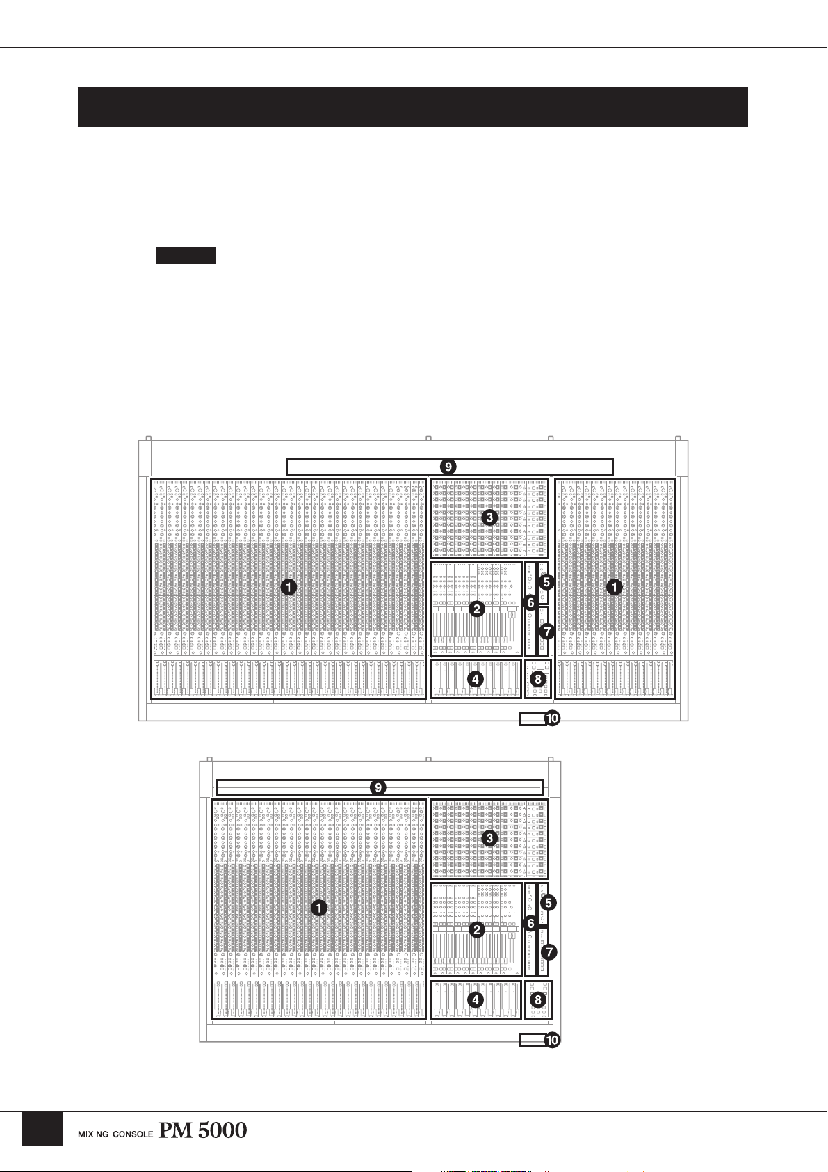
Panel Layout
Top Panel
The layout of the PM5000’s functional sections in the basic configuration is shown below. In the PM500052C the master output section is located in the center of the console, while in all other models it is located
to the right of the console.
NOTE
In this manual the console’s main functional groups are referred to as “sections.” Each section further contains “blocks” of
functions. The basic hardware divisions are “modules.” For example, all of the console’s input modules make up the “input
channel section.” Each input channel is made up of an “EQ block,” a “fader block,” and others. In the PM5000 each input
channel is made up of two separate hardware components: an “input channel module” and a “fader module.”
PM5000-52C
10
PM5000-28
Page 11

PM5000 Overview
1 Input Channel Section (page 15)
Two types of input channels are provided – mono and
stereo – but the basic block structure of each is the same.
After going through phantom power, input gain, phase
reversal, and high-pass filter stages, the audio signal
passes through a 4-band equalizer before it reaches the
channel fader. External processing gear can be inserted
into the channel signal path either before or after the EQ
block. The post-EQ signal can be sent to any or all of 12
stereo aux buses and 8 G/A (group/aux) buses. The audio
signal from the input channel can be assigned to the
stereo L&R bus and/or mono bus. On mono input
channels the signal can also be assigned to the stereo and
mono (center) buses in LCR mode. Up to 12 VCA
groups and 8 mute groups can be set for each channel’s
fader block. Furthermore, the channel on/off status,
master bus assign settings, grouping, and fader settings
can be stored in the console’s scene memory for instant
recall whenever required.
2 Master Output Section (page 26)
The master output section is further subdivided into
stereo aux master, G/A (group/aux) master, and stereo/
mono master sections. Each stereo aux master module
independently controls the signals from two adjacent
stereo aux buses (a total of 12 stereo aux buses).
Depending on the selected G/A bus mode, each G/A
master module can handle the signals from two adjacent
group/aux buses as up to 4 stereo pairs or 8 mono feeds.
The stereo and mono masters are integrated into a single
module, but are independent internally. The stereo and
mono masters receive the signals from the stereo and
mono buses, respectively, and send these signals to the
stereo and mono main outputs. Each master features a
SUB IN input and a [SUM GAIN] control for gain
adjustment. The on/off status of each master, as well as
bus assign and other settings can be stored in the
console’s scene memory.
3
Matrix Send and Master Out Section (page 35)
The matrix section is made up of 4 stereo and 8 mono
matrix mixes. The sends to the matrix mixes are all
derived from the master output section. The matrix input
section is located at the top of the master output section.
The signal from each master can be sent to a matrix bus
by turning the master’s [TO MATRIX] switch on and
using the matrix level controls to apply the signal to the
required matrix bus. The [SUB IN] control located next
to the stereo/mono master [SEND LEVEL] control
adjusts the level of the [MATRIX SUB IN L&R] signal
sent to each matrix bus.
The matrix output section is located to the right of the
matrix input section, and it is here that the final matrix
bus output levels are set. The stereo matrix buses can be
switched to function as mono sends via a utility mode
function, in which case the summed L & R mono signal
is delivered via the L and R outputs. The on/off status of
the matrix outputs can be stored in the console’s scene
memory.
4 VCA Master Section (page 21)
The VCA section can be used to independently control
up to 12 VCA groups (VCA1 ~ VCA12) set up via the
fader blocks of each input channel. The VCA master
faders function as master faders for the corresponding
VCA groups, while the [VCA MUTE] switches mute or
un-mute the corresponding VCA groups. With this
versatile system it is possible to assign a channel to
multiple VCA groups set up for different purposes.
5 Oscillator/Talkback Section (page 38)
From this section the oscillator and talkback signals can
be sent to any of the console’s master and matrix sends.
The [TB/OSC] switches in the master and matrix
sections assign the oscillator and talkback signals to the
corresponding output.
6 Monitor Control Section (page 40)
With two monitor outputs (MONITOR A & B) and
[CUE] switches on each module, any source or
combination of sources can be monitored as required.
Normally the same monitor signal is delivered via the
two main monitor outputs as well as the console’s three
headphone jacks (one at the top of the monitor module,
and two on either side of the front panel). When the
[LCR] switch is engaged the MONITOR A and B
outputs can be used simultaneously for LCR monitoring.
The [SOLO MODE] switches on the meter bridge allow
the module [CUE] switches to be used as solo switches
independently for the console’s input and output sections
(CUE/SOLO function).
11
Page 12
PM5000 Overview
7 Mute Master Section (page 21)
The 8 [MUTE MASTER] switches can be used to mute
specified input channel groups, or as [DIRECT
RECALL] switches for the scene memory. Whether
these switches function in the MUTE MASTER or
DIRECT RECALL mode is specified via a utility mode
function.
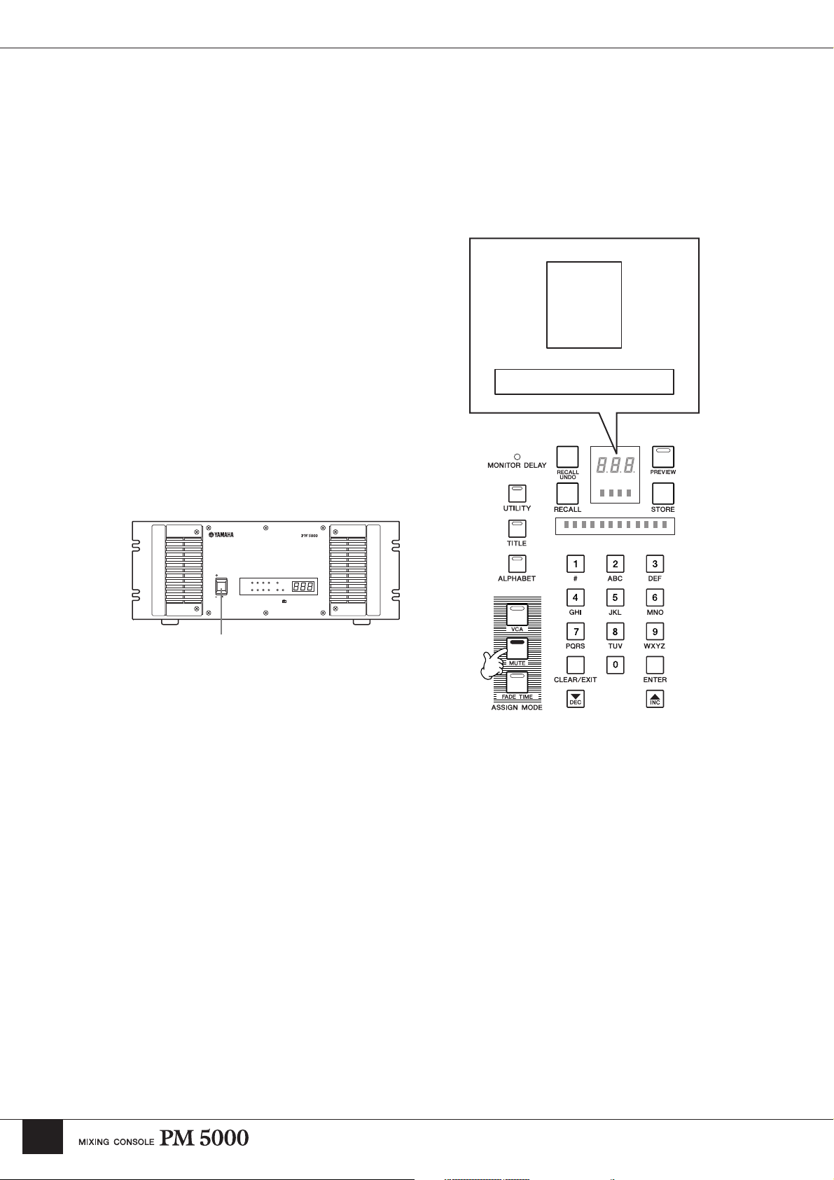
8 Digital Control Section (page 49)
The PM5000’s digital control features are concentrated
in this section. One of the main functions of this section
is storage and recall of console settings to and from the
scene memory. In addition to memorizing the on/off
status of panel switches, the scene memory can also
store fader settings that will be reproduced by the
motorized channel and VCA faders when recalled. A
fader time function is provided to specify the amount of
time it will take for the faders to physically reach the
recalled settings. This section also provides access to
utility functions that define basic operation of the
console and the way it interacts with some types of
external equipment. External CF (CompactFlash)
memory cards can be initialized and used to store scene
memory data.
9 Meter Bridge (page 47)
Used in conjunction with the monitor control section, the
meter bridge’s LED bar-graph meters provide visual
monitoring of final output levels at the console’s rearpanel outputs. Indicators are also provided to display the
status of the PW5000 Power Supply unit as well as the
console’s internal fan unit and phantom power supplies.
Brightness controls for the console’s illuminated
controls and gooseneck lamps are also provided. Other
controls provided on the meter bridge are scene memory
preview on/off and mode selectors for the CUE/SOLO
function.
) Memory Card Slot
The console's memory card reader is located on the front
panel. The PM5000 can use CF (CompactFlash)
memory cards (see page 59).
NOTE
The two screws on the right side of the digital control section can
be used to attach a protective cover. The six screws on the sides of
the master sections can be used to attach a book rest or a talkback
cable. These 8 screws do not affect the mechanical strength of the
unit. Use the attached screws or M3-size machine screws 8
millimeters or less in length.
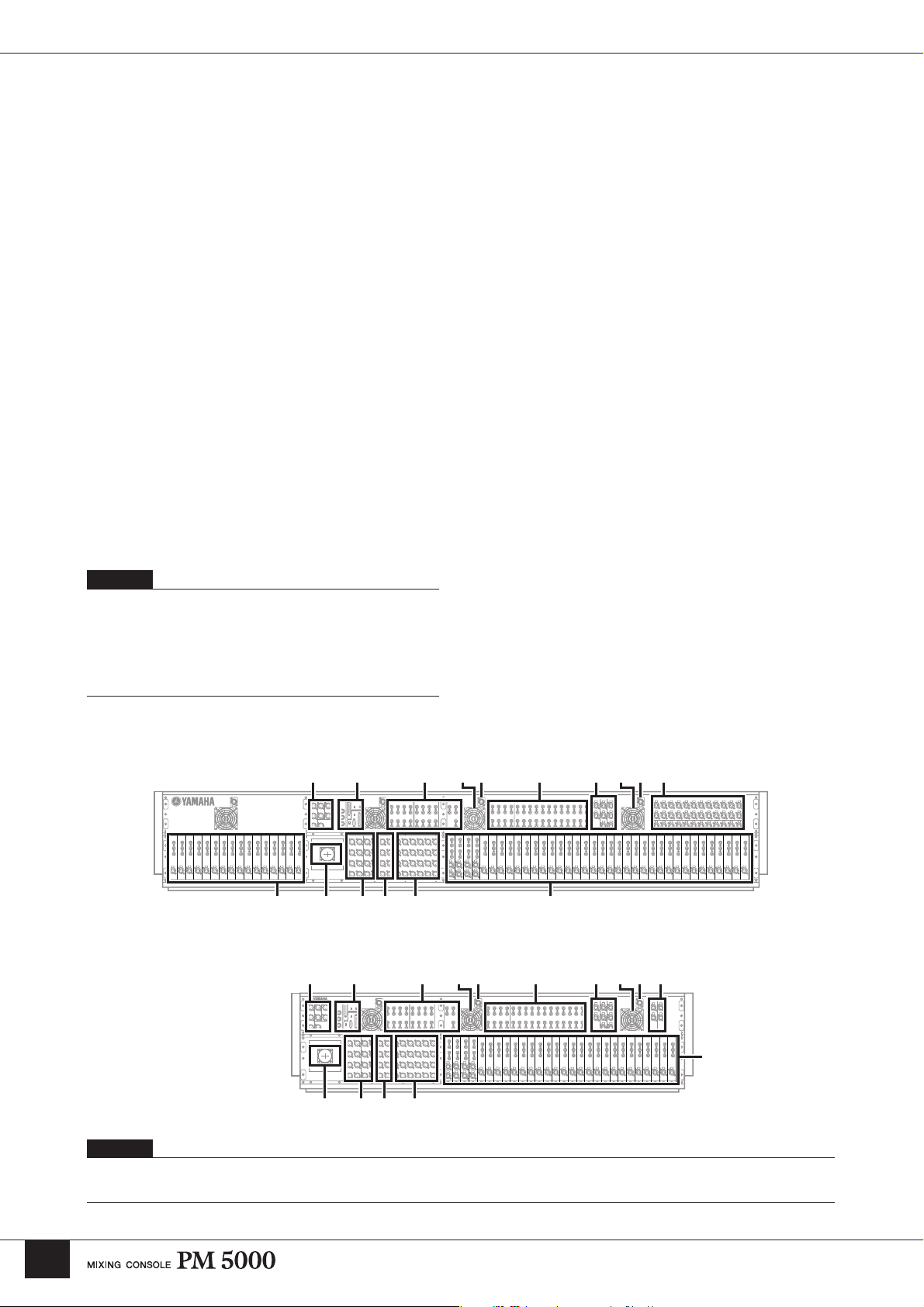
Rear Panel
PM5000-52C
&*( ™£¢
PM5000-28
&*( ™£¢
@##
º¡º¡
@
$%^! !∞
@##
º¡º¡
@
12
!
$%^∞
NOTE
All PM5000 inputs and outputs are balanced except for the PHONES outputs and expansion connectors. See the input/output specifications at the
end of this manual for details.
Page 13

PM5000 Overview
! Mono (Stereo) Inputs
XLR-type input connectors, DIRECT OUT connectors,
and INSERT IN and OUT connectors are provided on
each input channel. Stereo modules feature separate
connectors for the L and R channels, but do not have
DIRECT OUT connectors.
@ Sub Inputs
Each stereo aux master has L and R stereo aux SUB IN
connectors, each group/aux master has G/A SUB IN
connectors, both monitor outputs feature stereo 2TR IN
(1 & 2) and L/C/R CUE SUB IN connectors, and the
stereo and mono master outputs have L and R ST SUB
IN and MONO(C) SUB IN connectors. L and R
MATRIX SUB IN connectors are also provided for all
matrix outputs. Please check the supplied block diagram
for details.
NOTE
Stereo aux SUB IN and G/A SUB IN connectors are not provided
on the PM5000-28.
# Insert Inputs and Outputs
Insert input and output connectors are provided on all 12
stereo aux masters, 8 group/aux masters, the stereo and
mono masters, and the 4 stereo matrix and 8 mono
matrix outputs.
( Stereo Output and Mono Output
These are the stereo and mono master outputs (ST OUT,
MONO (C)).
º Lamp Connectors
The supplied gooseneck lamps can be connected here (4
connectors on the PM5000-52C, 3 on the PM5000-36
and PM5000-28). Lamp brightness can be adjusted via
the [LAMP DIMMER] control on the meter bridge.
Engage the [LAMP OFF] switch to turn the lamps off.
¡ Fan Vents
These are the air vents for the console’s internal cooling
fans (4 locations on the PM5000-52C, 3 on the PM500036 and PM5000-28). Be sure that the vents aren’t
blocked when installing the console.
™ Fan Switch
Sets the speed of the console’s internal cooling fans to
match prevailing operating conditions. Normally the
[LOW] setting can be used. When the ambient
temperature is high, however, such as in some outdoor
applications when the console is exposed to direct
sunlight, the [HIGH] setting should be used. Also switch
to the [HIGH] setting if the top-panel temperature feels
higher than normal.
$ Stereo Aux Master Out
% G/A (Group/Aux) Master Out
^ Matrix Out
The stereo aux master, G/A (group/aux) master, and
matrix output connectors are grouped together here.
& Monitor Out
These are the console’s two stereo monitor outputs (A &
B). You can use outputs A and B as separate stereo
monitor outputs, or use A and B simultaneously for LCR
monitoring (MONITOR B = Center).
* Talkback/Oscillator Out
The talkback or oscillator signal appears at this output.
£ +48V Master Switch
This is the master switch for the 48-volt phantom power
supply to all input channels. When using phantom power
use the individual input channel [+48V] switches to turn
phantom power on or off as required.
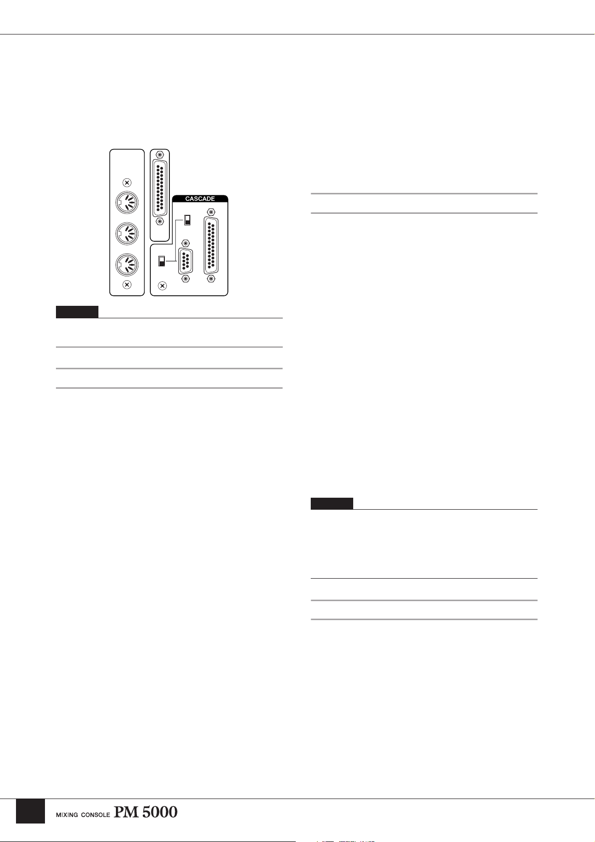
¢ External Expansion Connectors
Type A and B CASCADE connectors, a D-sub 25-pin
GPI connector, and MIDI IN/OUT/THRU connectors for
connection to compatible external equipment.
∞ Power Supply Connector
The dedicated external PW5000 power supply unit must
be connected to this connector using the power supply
cable supplied with the PM5000 console.
13
Page 14
PM5000 Overview
Expansion:Connecting to External Equipment
The PM5000 is entirely self-contained and can be used
effectively on its own, but it does provide some versatile
expansion capabilities. In this section we’ll describe how
the PM5000 can be synchronized with external gear and
Type B
The TYPE [B] cascade connector can be used to connect the
PM5000 to a Yamaha PM4000 or PM3500 series console for
linkage of the functions listed below. In this case the PM5000 will
function as the master console, there is no need to use the utility
mode to set the receive parameters. Cue/solo settings can,
however, be transmitted from the PM4000/3500.
cascaded with other Yamaha mixing consoles.
• VCA master section (mute & fade, fade time link).
MIDI
OUT
IN
RS232C
RS422
GPI
• Mute master (except for the PM3500).
• The cue/solo setting (sync of input cue only).
MIDI
The PM5000 MIDI connectors allow connection to other
MIDI equipment to provide the following capabilities:
THRU
MASTER
SLAVE
A
B
NOTE
See the detailed descriptions of the related utility functions in the
Utility Functions section beginning on page 56.
• Program change message reception from an external MIDI
device for scene memory selection.
• Transmission of appropriate program change messages to
external MIDI gear when a scene memory is recalled on the
PM5000.
• Control change reception from an external MIDI device for
control of PM5000 panel control values.
• Transmission of appropriate control change messages to
external MIDI gear when a panel control is operated on the
PM5000.
Cascade
Two types of cascade connectors are provided on the
PM5000 rear panel: TYPE [A] for connection to a
second PM5000, and TYPE [B] for connection to
Yamaha PM4000/3500 series mixing consoles. In either
case the extra console will be added to increase the total
number of available input channels.
Type A
When the TYPE [A] connectors of two PM5000 consoles are
connected via a cross cable the functions listed below become
linked between the master and slave consoles. The slave console’s
utility mode can be used to specify reception of individual
parameters.
• VCA master section (mute & fade, fade time link).
• Mute master.
• The cue/solo setting (sync of all cue groups).
• Scene memory (synchronized storage and recall of the same
scene number).
The TYPE [A] port can also be connected to the serial RS-422 or
RS-232C port of a personal computer for offline console parameter
editing. PM5000 setup data can be transferred to and from the
console in standard CSV file format and edited in any spreadsheet
application that can import and export CSV data. The edited data
can then be directly read back into the PM5000.
In order to select the PM5000’s 1000 internal scene
memories using MIDI program change messages 1~128
it is necessary to use program change bank select
messages or create an program change table for the
PM5000. The program change table will also determine
which program change number is transmitted by the
PM5000 when a scene memory is recalled. MIDI
settings can be accessed via the console’s utility
functions. Also refer to the MIDI data list at the end of
this manual.
NOTE
Appropriate MIDI cables must be connected from the OUT
connector of the transmitting device to the IN connector of the
receiving device. The THRU connector on the receiving devices
re-transmits the data received at the IN connector. On the
PM5000 an “echo” function can be used to retransmit data
received at the IN connector via the OUT connector.
GPI (General Purpose Interface)
The GPI port allows pulse-signal interfacing with
compatible external equipment for bi-directional control
of several functions. Receive functions include
incrementing or decrementing of the PM5000 scene
memory and talkback on/off switching. GPI data can be
transmitted when a fader is operated (manually or
automatically), or when a specified scene memory is
recalled. All of these functions are accessible via the
PM5000 utility functions. Refer to the GPI Pin
Assignments chart at the end of this manual for more
information.
14
Page 15
Input Channel Section
Input Channel Section
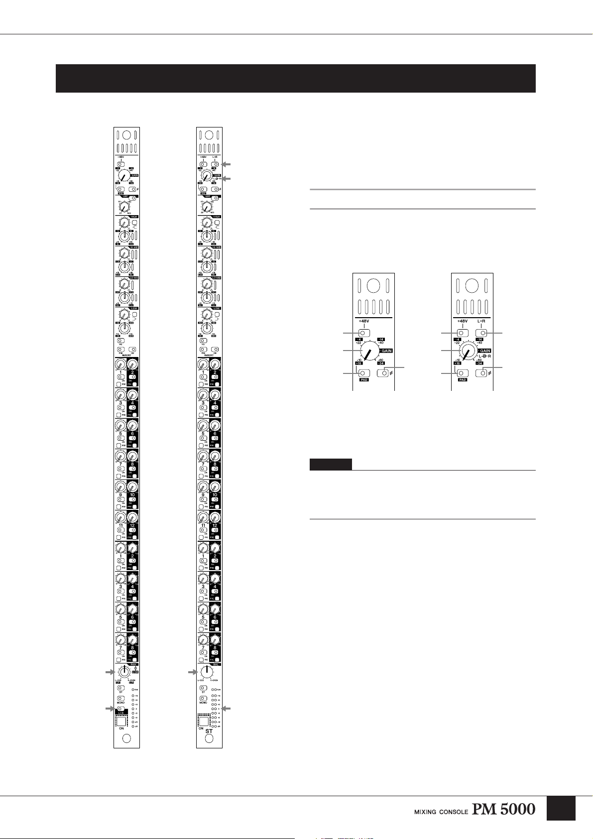
Mono Input
Module
Stereo Input
Module
Mono and Stereo Input Modules
Mono and stereo input modules make up the console’s
input channel section. In essence each stereo module
contains two parallel mono signal paths, and the panel
controls control both channels simultaneously.
Head Amp Block
Initial adjustment of the input audio signal level and
other parameters can be carried out here.
Mono Input
Module
1 14
3 3
2 2
Stereo Input
Module
55
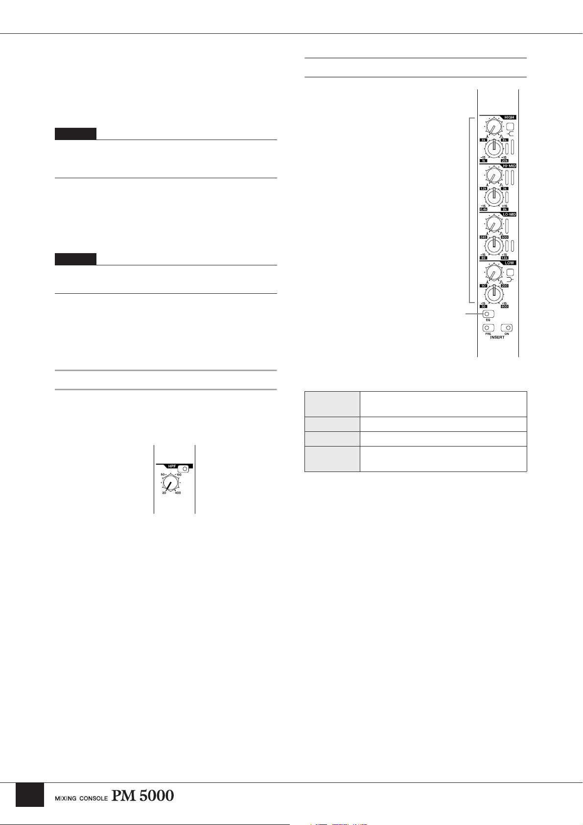
1 [+48V] Switch
Engage this switch to supply +40-volt phantom power to
the corresponding input.
NOTE
In order to use phantom power, the rear-panel [+48V MASTER]
switch must be turned on. The [+48V MASTER ON] indicator on
the left side of the meter bridge will light when the master
phantom power switch is on.
2 [PAD] Switch
When this switch is engaged a 26-db pad is inserted at
the channel’s input to compensate for high-level source
signals.
The arrows indicate controls and indicators that differ
between the mono and stereo input modules.
15
Page 16
Input Channel Section
3 [GAIN] Control
Adjusts the input level. When the [PAD] switch is off the
input level can be adjusted from –10 dB through –60 dB.
When the [PAD] switch is engaged the range is from +16
dB through –34 dB.
NOTE
Stereo modules feature concentric gain controls: the inner control
adjusts the gain of the left channel and the outer control adjusts
the gain of the right channel.
4 [L+R] Switch (stereo modules only)
When this switch is engaged the stereo input signal is
summed to a mono mix, allowing the stereo input
modules to be used as mono input modules, as required.
NOTE
To maintain the proper subjective signal level the left and right
channels are attenuated by 3 dB.
5 [ø] (Phase) Switch
Engaging this switch reverses the phase (also referred to
as the “polarity”) of the input signal.
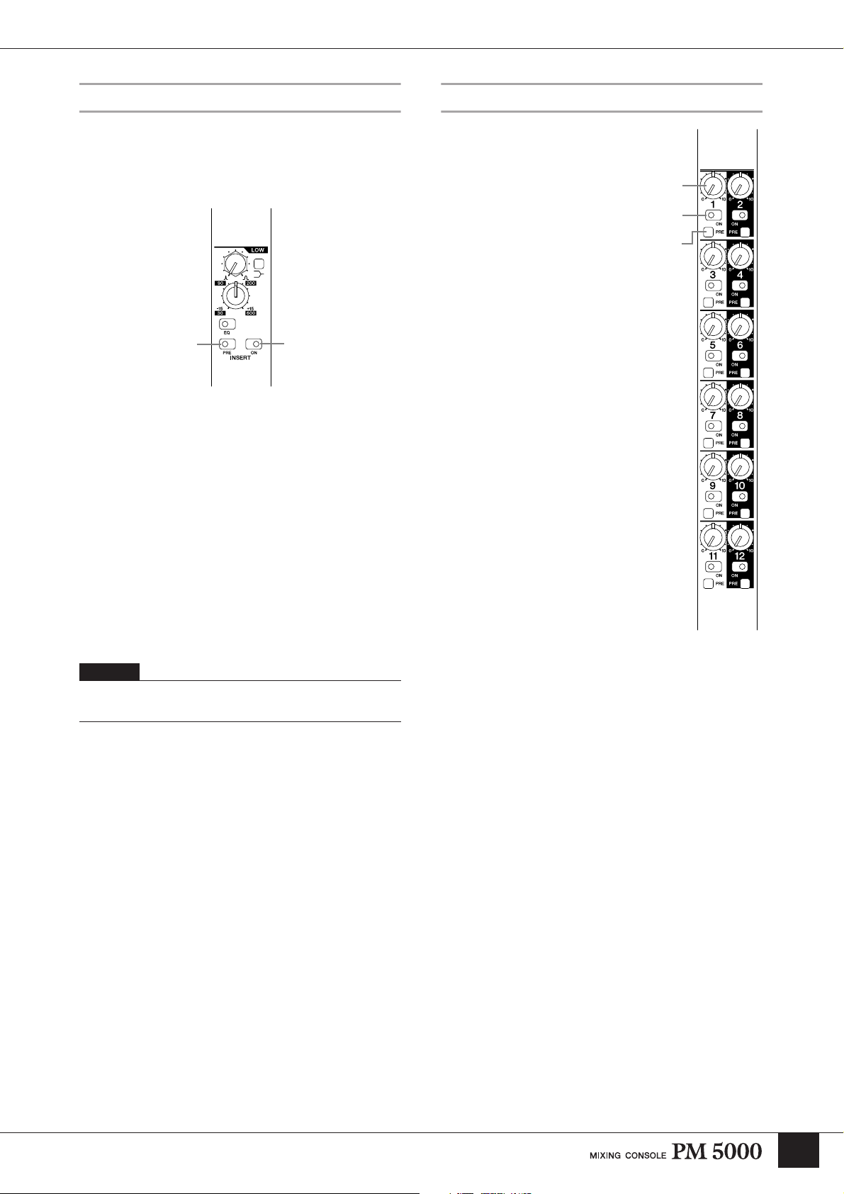
HPF Block
EQ Block
This 4-band equalizer features
individually-adjustable HIGH,
HI-MID, LO-MID, and LOW
bands for versatile shaping of
the channel signal. The HIGH
and LOW bands are switchable
between shelving and peaking
operation, while the HI-MID
and LO-MID bands are peaking
types.
7 EQ Controls
Two controls are provided for
each EQ band: the upper “Q”
control adjusts bandwidth,
while the lower concentric
control adjusts frequency (outer
control) and gain (inner
control). The HIGH and LOW
bands additionally have a
peaking/shelving switch that
determines the band’s mode of
operation: engaging the switch
selects the shelving mode.
7
8
The high-pass filter can be used to attenuate unwanted
low-frequency noise that can adversely affect the overall
sound.
6
6 [HPF] Switch and Control
The filter is activated when the switch engaged, and the
control can be used to adjust the high-pass filter cutoff
frequency from 20 Hz through 400 Hz. The filter has a
12-dB/oct. cutoff slope.
HIGH
HI-MID 400 Hz ~ 8 kHz, -15 dB ~ +15 dB
LO-MID 80 Hz ~ 1.6 kHz, -15 dB ~ +15 dB
LOW
* For all bands Q (bandwidth) can be adjusted from 0.5 ~ 3.0.
1 kHz ~ 20 kHz, -15 dB ~ +15 dB (peaking
and shelving modes)
30 Hz ~ 600 Hz, -15 dB ~ +15 dB (peaking
and shelving modes)
8 [EQ] Switch
Turns the 4-band EQ block on or off. When the [EQ]
switch indicator is off the EQ circuitry is bypassed. EQ
is active when the indicator is lit.
16
Page 17
Input Channel Section
Insert Block
These switches are used to determine whether and where
external processing gear connected to the rear-panel
INSERT IN and OUT connectors will be inserted into
the channel signal path.
)
9 Insert [ON] Switch
Turns channel insert on or off. When the [ON] switch is
engaged an external equipment connected to the rearpanel INSERT IN connectors is inserted into the
channel’s signal path. The [PRE] switch (below)
determines whether the insert is pre- or post-EQ.
) [PRE] Switch
Determines whether the channel’s INSERT IN and OUT
connectors insert the externally connected gear before or
after the channel EQ stage. When the switch is off the
insert is post-EQ. When on (when the indicator is lit) the
insert is pre-EQ.
9
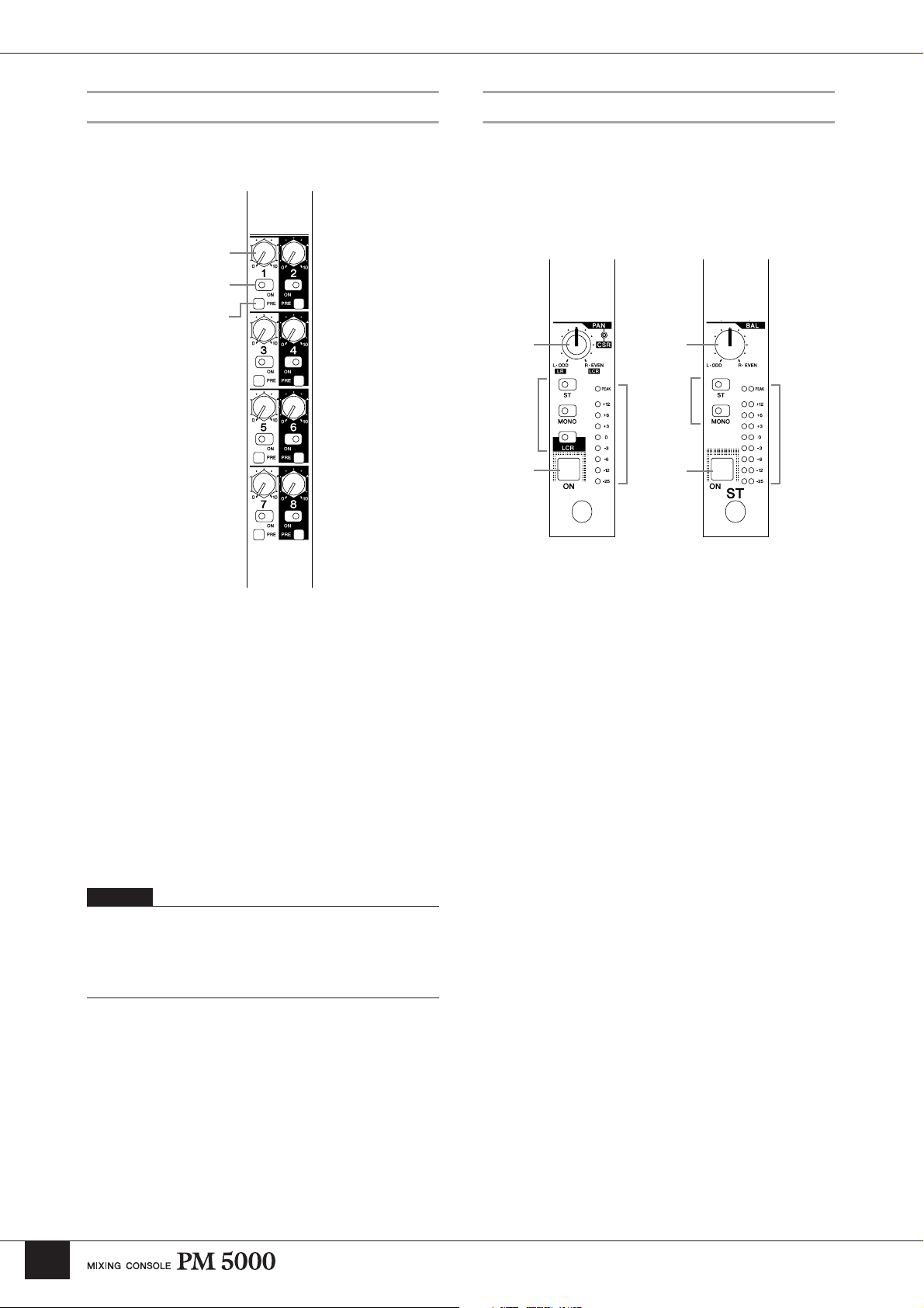
Stereo Aux Send 1~12 Block
The controls in this block determine
the levels at which the channel signal is
sent to the console’s 12 stereo aux
buses.
!
Send Level and Pan Controls
(mono modules)
Send Level and Balance
Controls (stereo modules)
The inner controls adjust send level (0
dB at approximately 2 o’clock), and
the outer controls adjust pan for mono
modules or balance for stereo modules.
@ [ON] Switch
When an [ON] switch is engaged the
send to the corresponding aux bus is
active.
# [PRE] Switch
When this switch is engaged the prefader signal is sent to the
corresponding aux bus. When off, the
post-fader signal is sent to the aux bus.
!
@
#
NOTE
The channel signal appears at the rear-panel INSERT OUT
connector whether the INSERT [ON] switch is engaged or not.
17
Page 18
Input Channel Section
G/A (Group/Aux) Send 1~8 Block
These controls determine how the channel signal is sent
to the console’s 8 group/aux buses.
$
%
^
Main Out Block
This block determines how the channel signal is
assigned to the console’s main stereo and mono (center)
buses. The stereo and mono outputs can be used
independently, or combined for LCR output.
&
(
Mono Input
Module
*
(
Stereo Input
Module
¡¡
º
º
$ Send Level Controls
Adjust send level to the corresponding group/aux bus (0
dB at approximately 2 o’clock).
% [ON] Switch
When an [ON] switch is engaged the send to the
corresponding group/aux bus is active.
^ [PRE] Switch
When this switch is engaged the pre-fader signal is sent
to the corresponding group/aux bus. When off, the postfader signal is sent to the group/aux bus.
NOTE
The above descriptions apply when the group/aux buses are used
as 8 mono aux buses (the default mode). The functions of the
controls will vary depending on the G/A bus mode selected via
the group/aux master section – refer to “Group/Aux Switching”
on page 32 for details.
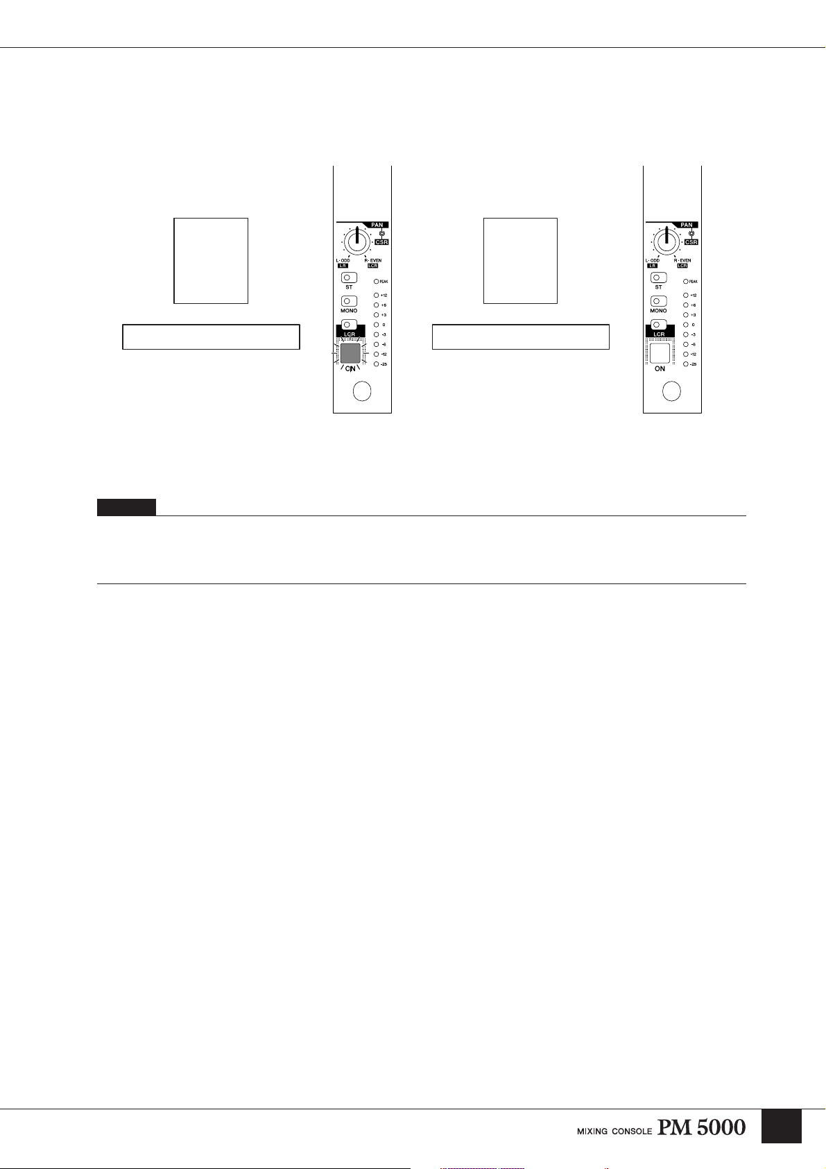
& [PAN]/[CSR] Control
(mono modules only)
Adjusts panning of the signal sent to the bus(es) to which
the channel signal is assigned via the main out switches
(. When the [ST] switch is engaged, assigning the
channel signal to the stereo bus, stereo panning is
adjusted via the inner control. When the [LCR] switch is
engaged and the channel signal is assigned to both the
stereo and mono buses in LCR mode, the outer [CSR]
(Center-Side Ratio) control can be used – refer to the
column below.
* [BAL] Control (stereo modules only)
Determines the stereo balance when the stereo-module
[ST] main out switch is engaged to send the channel
signal to the stereo bus.
18
Page 19
Input Channel Section
( Main Out Switches
Determine where the post-fader channel signal will be
sent. To assign the channel signal to the stereo bus
engage the [ST] switch and use the [PAN] & or [BAL]
* control to adjust the stereo image. To send the signal
to the mono bus engage the [MONO] switch. In all cases
the channel fader determines the signal level.
On mono modules it is also possible to send the channel
signal to the stereo and mono buses in LCR mode, using
the mono bus as the center signal. To do this engage the
[LCR] switch and use the [CSR] control & to adjusts the
Center-Side Ratio to achieve the desired LCR balance.
º Channel [ON] Switch
Turns the input channel on or off. When off the channel
signal is not sent to the STEREO AUX, GROUP AUX,
STEREO or MONO buses.
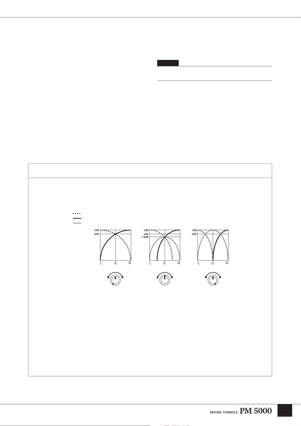
LCR vs. Stereo + Mono Operation
¡ Level Meter
Displays the channels post-EQ pre-fader signal level.
The [PEAK] indicator will light when the signal level
exceeds 17 dB above nominal (0 dB) level.
NOTE
The [PEAK] indicator responds to the pre-EQ and pre-insert
signal level as well as to the post-EQ pre-fader level.
When the [LCR] switch is engaged the stereo and mono (center) buses become linked for LCR operation and the
[ST] and [MONO] switches cannot be engaged. On the other hand, when the [LCR] switch is not engaged the [ST]
and [MONO] switches can be engaged simultaneously. In either case the channel signal is sent to both the stereo and
mono buses. The difference between these two setups is described below.
L Bus Level
R Bus Level
MONO(C) Bus Level
Outer: CSR
Inner: PAN
LR CSR LR CSR LR CSR
CSR Control: LR CSR Control: Center CSR Control: CSR
For example, mono sources are normally positioned in the stereo sound field or swept from one side to the other by
adjusting the panning to the stereo bus. This works fine when the distance between the left and right speakers is
relatively small, but problems arise in venues where the speakers are further apart. In fact, in even modest venues if
a channel is panned fully left, for example, audience members sitting on the right side of the house will hear very
little of that signal, if any. In such cases it is useful to provide a center channel, the output level of which will be
adjusted to reinforce the stereo image and provide more effective coverage. Manually adjusting the levels and
panning of the stereo and mono buses to achieve this effect can be extremely difficult, and that’s where the LCR
output mode with CSR (Center-Side Ratio) control comes in handy. With this system and an LCR speaker setup it is
possible to produce natural stereo positioning and smooth panning in large venues with a single control. The [PAN]
control adjusts panning as always, while the [CSR] control determines how the center channel responds to [PAN]
control operation as shown in the diagrams above. The more the [CSR] control is rotated clockwise, the higher the
center channel level as the [PAN] control approaches center position.
19
Page 20
Input Channel Section
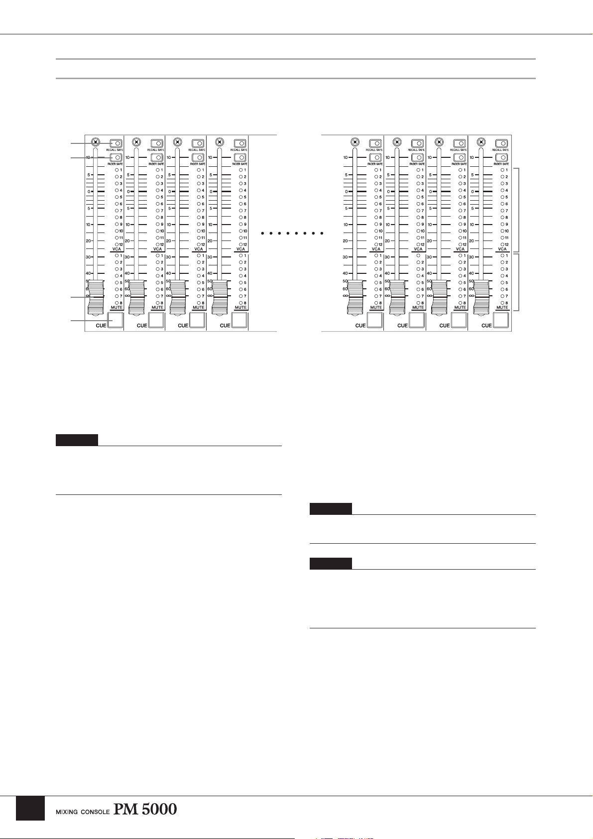
Channel Fader Block
The channel faders determine the level of the channel signal sent to the console’s master buses, and are of primary
importance in setting up the balance between the various channels in the mix. The channel faders can also be assigned to
specific VCA and mute groups for group level and mute control.
£
¢
™
∞
§
¶
™ Channel Fader
Adjusts the out signal level from the corresponding
channel. The channel faders also affect the signal level
sent to the stereo aux and group/aux buses when the
[PRE] switches associated with the corresponding sends
are off (i.e. they are sending the post-fader signal).
NOTE
The channel faders are motor-drive types that will physically
move to the memorized settings when a scene memory is recalled
– after the specified “fade time,” if one has been programmed.
Refer to “Scene Memory Functions” on page 51 for details.
£ [RECALL SAFE] Switch
¢ [FADER SAFE] Switch
Either of these switches can be engaged to prevent the
corresponding data from changing the channel settings
when a scene memory is recalled. Use the [RECALL
SAFE] switch to maintain the master bus assign switch
settings, or [FADER SAFE] switch to maintain the level
of the channel fader.
§ MUTE Indicators 1~8
Indicate the mute groups to which the corresponding
channel is assigned. More details are provided in the
“Channel Grouping” section.
¶ [CUE] Switch
When this switch is engaged the pre-fader channel signal
is sent to the console’s CUE L&R buses regardless of the
channel’s on/off status. The cue signal can be monitored
via the rear-panel MONITOR OUT connectors or any of
the console’s PHONES jacks.
NOTE
Using the VCA CUE function, the post-fader channel signal can
be monitored.
NOTE
The [CUE] switches are also used to assign channels to VCA and
mute groups (page 21), as well as to specify target channels when
setting fade time parameters (page 52). Normal [CUE] switch
function is suspended while any of these operations are in
progress.
20
∞ VCA Indicators 1~12
Indicate the VCA groups to which the corresponding
channel fader is assigned. If a VCA group master to
which the channel is assigned is muted via its [VCA
MUTE] switch, the corresponding VCA indicator will
flash rather than light continuously. More details are
provided in the “Channel Grouping” section on page 21.
Page 21
Channel Grouping
This section will describe how channels can be assigned to VCA and mute groups.
Input Channel Section
VCA Master Section Mute Master
VCA 1 VCA 12VCA 11VCA 10VCA 3VCA 2
VCA Grouping
The PM5000 provides two methods of “grouping” input
channels so that they can be controlled via a single
master fader while maintaining the level relationship
between the individual channels in the group. The
traditional method is to send the channel signals to any
of the console’s 12 stereo aux or 8 mono group/aux
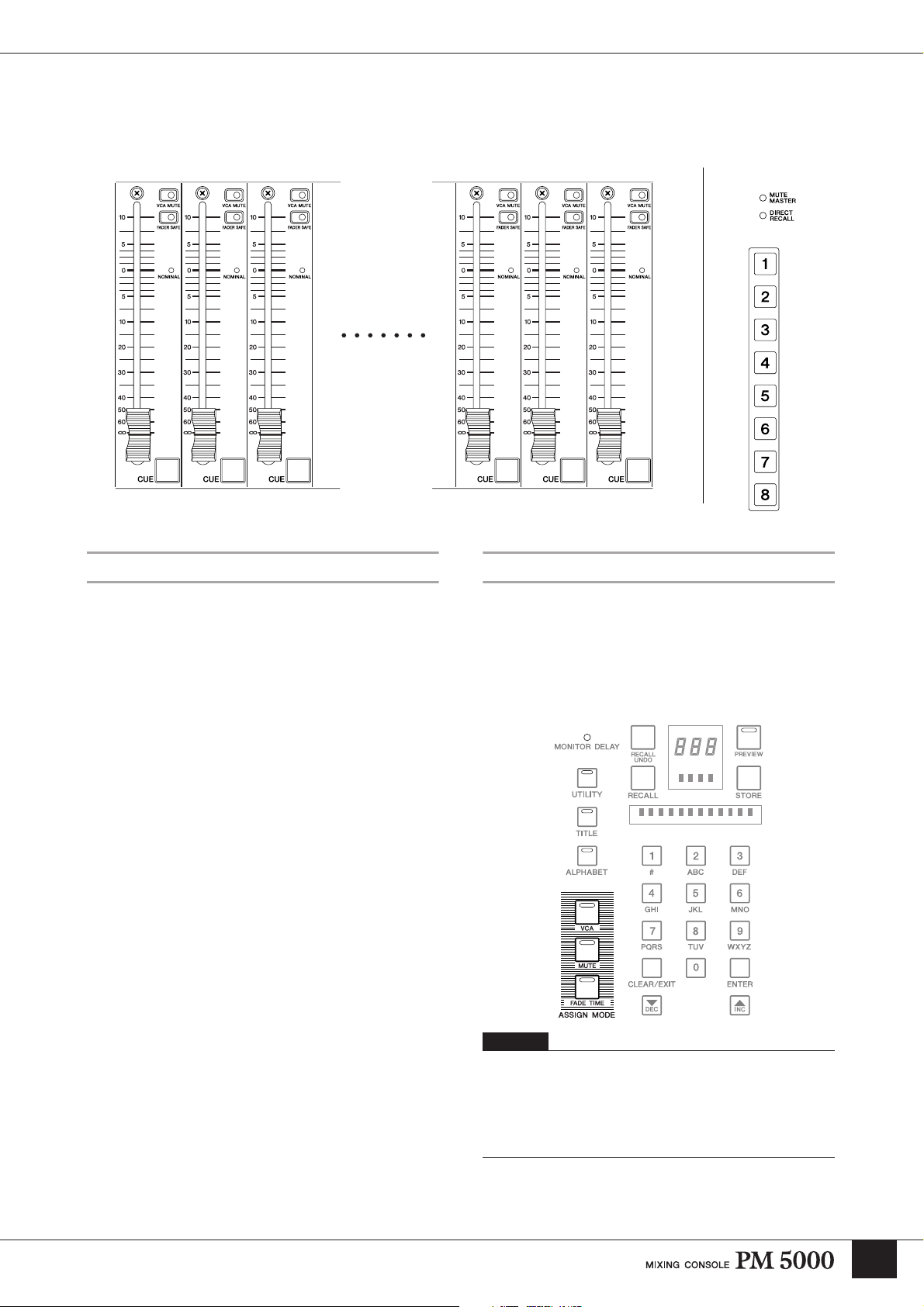
Assigning VCA and Mute Groups
Each input channel can be freely assigned to any of 12
VCA groups and 8 mute groups for group level control
via the VCA master faders or group muting via the mute
master switches. VCA or mute group assignment is
initiated by using the ASSIGN MODE keys in the
PM5000’s digital control section.
buses and use the bus master fader for group control.
The second method, pioneered by Yamaha’s introduction
of VCA-controlled groups in the PM3000 console, is to
directly control the levels and muting of the channels
assigned to a group via voltage control. The main
advantage of this system is that a number of different
group configurations – for different scenes in a show, for
example – can be set up beforehand and then recalled
instantaneously as needed. This type of speed and
flexibility is simply not possible using the traditional
group bus assignment method.
Switches
NOTE
The ASSIGN MODE keys include a [FADE TIME] key which
will not be discussed here. Fade time assignment specifies the
amount of time it will take the motor faders to reach the recalled
fader levels when a scene memory is recalled. Refer to the “Scene
Memory Functions” section on page 51 for details concerning the
fade time function.
21
Page 22
Input Channel Section
VCA Group Assignment Procedure
1 Press the ASSIGN MODE [VCA] key to initiate the assignment procedure (the indicator will flash).
2 Engage a VCA master [CUE] switch to specify the VCA master to which a channel or multiple channels are to be
assigned. The [CUE] switch will flash. If any input channels are already assigned to the selected VCA master, their
corresponding VCA indicators will flash.
3 Engage the [CUE] switches of the input channels to be assigned to the selected VCA master (the corresponding VCA
indicators will flash). To undo an assignment simply press the channel [CUE] switch a second time (the VCA
indicator will go out).
VCA Fader Channel Fader
VCA 1 1234 56 7
4 Repeat step 3 for all input channels to be assigned to the selected VCA master.
5 If a different VCA master [CUE] switch is pressed at this point the target VCA master will change accordingly and
new channel assignments can be made. All channel assignments to the previously-selected VCA master will be
confirmed and their corresponding VCA indicators will light.
6 Channel assignments can now be made to the newly-selected VCA master.
VCA Fader Channel Fader
1234 5 6 7VCA 2VCA 1
22
7 Press the ASSIGN MODE [VCA] key to end the assignment procedure (its indicator will go out). Pressing any other
ASSIGN MODE key will also end the VCA assignment procedure – assignment will switch to the newly-selected
ASSIGN MODE.
NOTE
Normal [CUE] switch operation is suspended during the assignment procedure but the current cue settings are retained.
Page 23
Input Channel Section
Mute Group Assignment Procedure
1 Press the ASSIGN MODE [MUTE] key to initiate the assignment procedure (the indicator will flash).
2 Engage a mute master ([1] ~ [8]) switch to specify the muter master to which a channel or multiple channels are to be
assigned. The mute master switch will flash. If any input channels are already assigned to the selected mute master,
their corresponding MUTE indicators will flash.
3 Engage the [CUE] switches of the input channels to be assigned to the selected mute group (the corresponding
MUTE indicators will flash). To undo an assignment simply press the channel [CUE] switch a second time (the
MUTE indicator will go out).
Mute Master Switch Channel Fader
1234 5 6 7
4 Repeat step 3 for all input channels to be assigned to the selected mute group.
5 If a different mute master switch is pressed at this point the target mute group will change accordingly and new
channel assignments can be made. All channel assignments to the previously-selected mute group will be confirmed
and their corresponding MUTE indicators will light.
6 Channel assignments can now be made to the newly-selected mute group.
Mute Master Switch Channel Fader
1234 5 6 7
7 Press the ASSIGN MODE [MUTE] key to end the assignment procedure (its indicator will go out). Pressing any
other ASSIGN MODE key will also end the mute group assignment procedure – assignment will switch to the newlyselected ASSIGN MODE.
NOTE
Normal [CUE] switch operation is suspended during the assignment procedure but the current cue settings are retained.
23
Page 24
Input Channel Section
VCA Master and Master Mute Switch Group Control
If a number of input channels are assigned to VCA masters or mute master switches as described in the preceding
section, those channels can be controlled as a group from a single fader or mute switch.
VCA Section
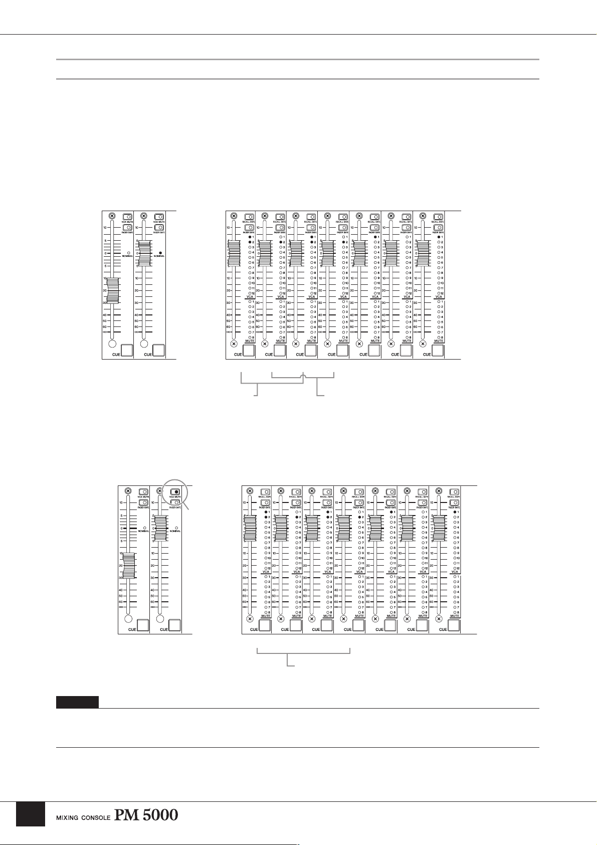
VCA master faders 1 ~ 12 function as group faders for the assigned input channels, adjusting the output level of all
assigned channels while maintaining the level relationships between them. The final fader level of each channel will be
the sum of the channel fader and VCA fader settings. In the example below input channels 1, 3, 5, and 7 are assigned to
VCA group 1 while input channels 1 through 4 are assigned to the VCA 2 group.
VCA Faders Channel Faders
VCA 2VCA 1 1234 5 6 7
Since the VCA 1 fader is set to –20 dB and the
VCA 2 fader is set to 0 dB, the final fader levels
of channels 1 and 3, which are assigned to both
VCA 1 and VCA 2, will 20-dB lower than the
input channel fader settings.
Since the VCA 2 fader is set to 0 dB (nominal), the
final fader levels of input channels 2 and 4 will
correspond exactly to their respective channel fader
settings.
In the same way, the [VCA MUTE] switches on the VCA master modules function as group mute switches for the
assigned input channels.
VCA Faders Channel Faders
[VCA MUTE]
Switch
1234 5 6 7VCA 2VCA 1
24
Since the VCA 2 [VCA MUTE] switch is engaged
the final fader level of input channels 1 ~ 4 will be -∞.
NOTE
The [VCA MUTE] switches function in a slightly different way than the mute master switches. When a [VCA MUTE] switch is engaged the
effect is the same as turning that VCA fader all the way down to -∞. The mute master switches, on the other hand, disengage the channel [ON]
switches of the assigned channels.
Page 25
Input Channel Section
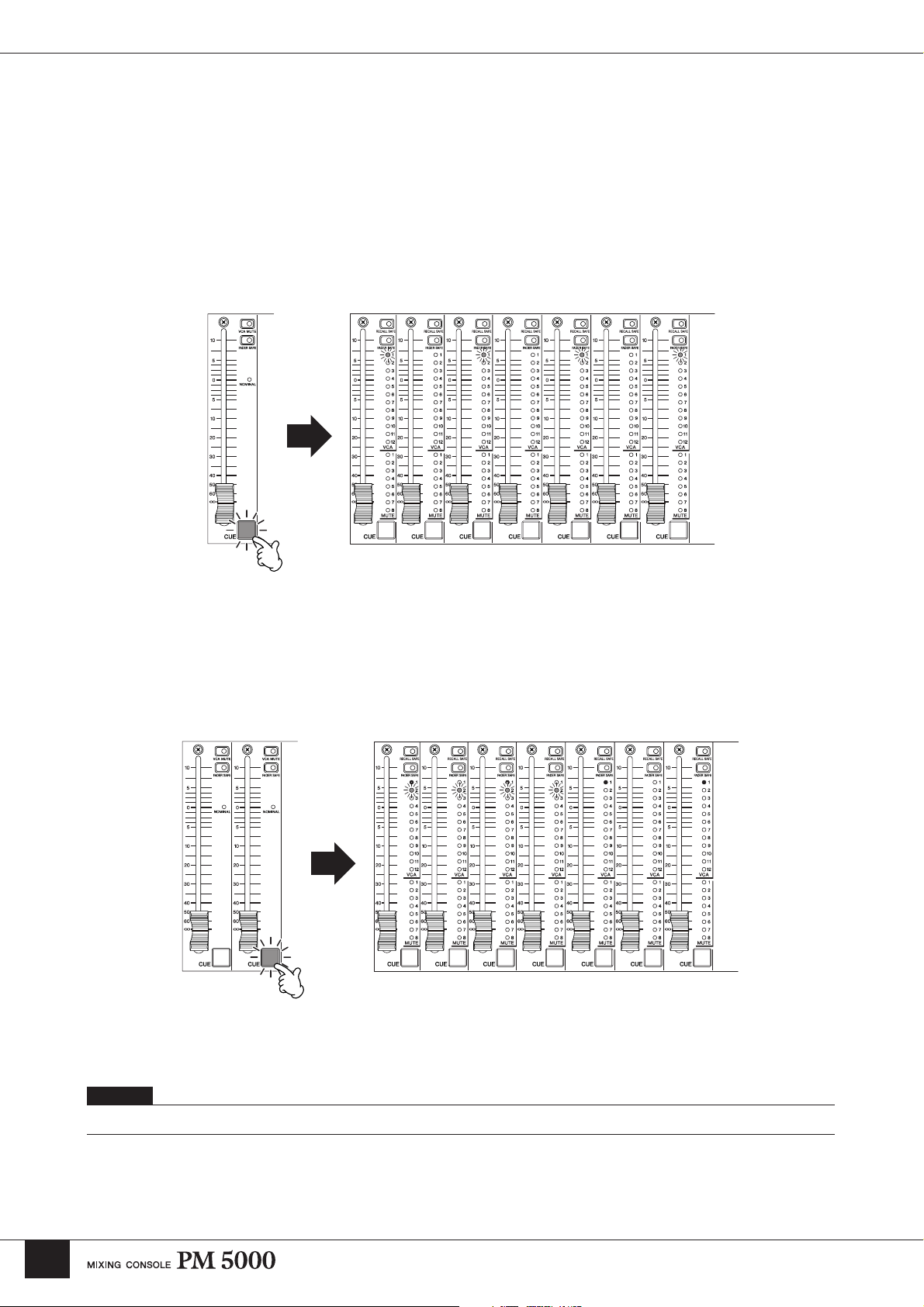
The VCA 1 ~ VCA 12 [CUE] switches function as group cue switches for all assigned input channels. When a VCA
master [CUE] switch is engaged it will light, while the [CUE] switches of all assigned channels will flash, and the signals
from those channels will be routed to the console’s cue (L&R, C) buses for monitoring.
VCA Faders Channel Faders
1234 5 6 7VCA 2VCA 1
Channels 1 and 3 can be monitored by engaging either the
VCA 1 or VCA 2 [CUE] switch.
NOTE
Refer to the “Monitor Control Section” on page 40 for more details.
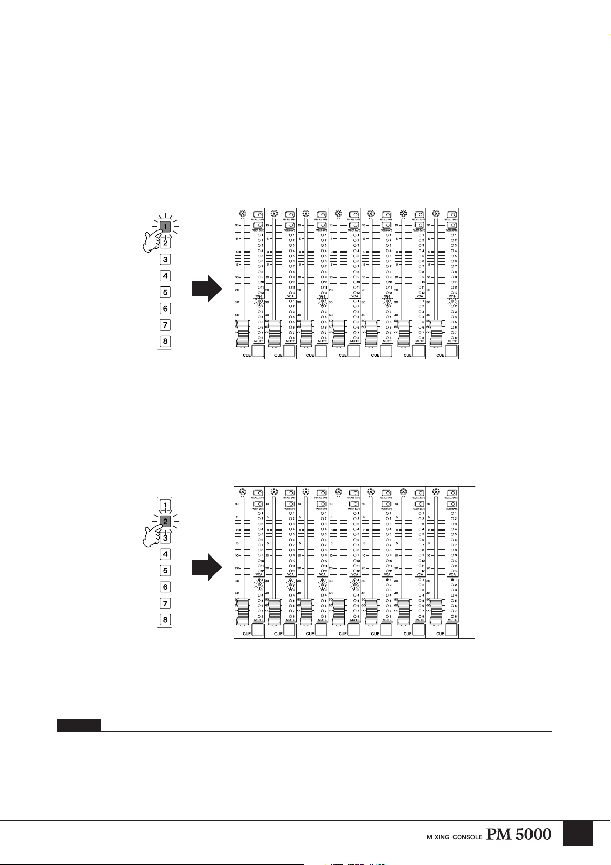
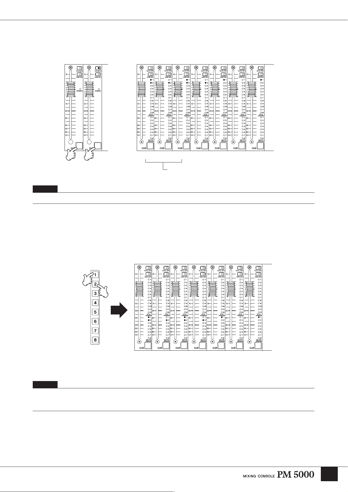
The Mute Master Switches
Mute master switches [1] ~ [8] function as group mute switches for the assigned input channels.
Press any of the MUTE MASTER switches, [1] ~ [8], to mute the assigned channels. You can configure the channel [ON]
switches to either flash or go out entirely when muted, as described on page 25-1.
Mute Master Switches Channel Faders
1234 5 6 7
In this setup channels 1 and 3 can be muted by engaging either the mute master [1] or [2] switch.
NOTE
If the mute safe function is on, the channel [RECALL SAFE] switches can be used to prevent specified channels in the group from being muted
when the assigned mute master switch is engaged (details on page 66). When the direct recall function is on and the [DIRECT RECALL]
indicator is lit, the mute master switches can not be used for group muting (details on page 71).
25
Page 26
Group Mute Channel [ON] Switch Indication Mode
When the channels assigned to a MUTE MASTER ([1] ~ [8]) switch are muted, the [ON] switches of the muted channels
can be set to either flash or go out entirely. Flashing is the initial default setting.
1 Enter the Group Mute Display Setup Mode by turning the power off, and then back on while holding the ASSIGN
MODE [MUTE] switch. Please note, however, that the console will automatically restart in the normal mode if no
operations are performed for 5 seconds.
M U T E
M O D E : B L I N K
PW5000
POWER
ON OFF
Power Switch
OPERATION MONITOR FAN LINE VOLTAGE
HIGH
NORMAL
+16 -16 +12 +48
STOPTHERMAL
CAUTION
FAN SPEED
AUTO HIGH
POWER SUPPLY
+
25-1
Page 27
2 While the Group Mute Display Setup Mode display is showing use the [INC]/[DEC] keys to select either “BLINK”
(the muted channel [ON] switches will flash) or “STATIC” (the muted channel [ON] switches will go out).
BLINK Mode
M U T E
M O D E : B L I N K
Flashing
STATIC Mode
M U T E
M O D E : S T A T I C
Going out
3 Press the [ENTER] key to confirm the selection and restart in the normal mode. Press the [CLEAR/EXIT] key if you
want to restart in the normal mode without altering the previous setting.
NOTE
• This setting is retained when the console power is turned off, but is not included in the setup memory and therefore can not be saved to a CF
memory card.
• When the STATIC mode is selected the [ON] switches will still flash when PREVIEW is engaged.
• When the STATIC mode is selected pressing the group-muted channel [ON] switches will be ignored.
25-2
Page 28
Master Out Section
Master Out Section
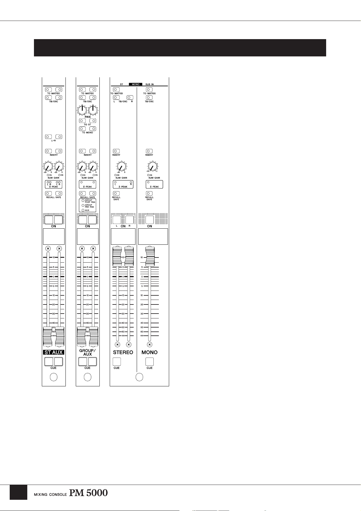
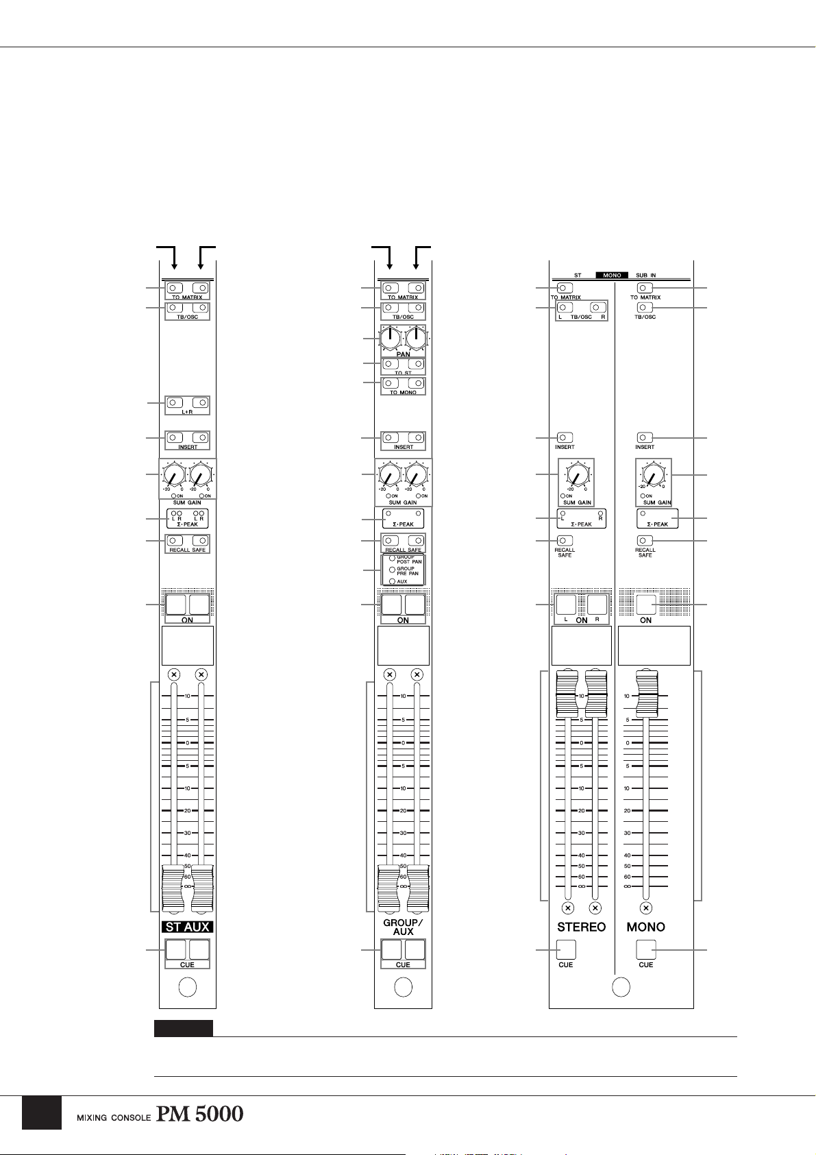
Stereo Aux
Master Module
G/A Master
Module
Stereo/Mono Master
Module
Multiple Masters In Single Modules
The master output section is made up of modules
housing the masters for 12 stereo aux buses, 8 G/A
(group/aux) buses, a stereo bus, and a mono bus. Both
the stereo aux and G/A master modules combine pairs of
adjacent masters – odd and even numbers – in each
module.
While the stereo aux master modules each handle two
stereo signal pairs, each G/A master module can be used
to handle two independent mono signals, a linked pair of
mono signals, or a stereo pair.
Similarly, the stereo/mono master module combines the
console’s main stereo and mono bus masters.
26
Page 29
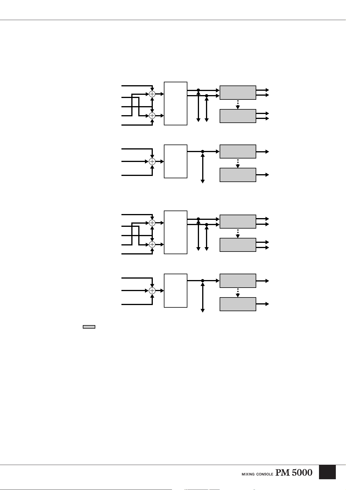
Basic Signal Routing
In the same was as the input channel modules, the only real difference between the stereo aux, G/A, stereo,
and mono masters is whether they are mono or stereo. The basic routing is the same for all signals, as
summarized in the diagrams below.
ST AUX
ST AUX L
ST AUX R
TB/OSC
ST AUX SUB IN L
ST AUX SUB IN R
G/A
G/A IN
TB/OSC
G/A SUB IN
SUM
GAIN
SUM
GAIN
INSERT
ST AUX
TO
MATRIX
G/A OUT
TO
MATRIX
Master Out Section
MASTER OUT
MATRIX
MASTER OUT
MATRIX
INSERT
STEREO
STEREO BUS IN L
STEREO BUS IN R
TB/OSC
STEREO SUB IN L
STEREO SUB IN R
SUM
GAIN
INSERT
STEREO
OUT
TO
MATRIX
MASTER OUT
MATRIX
MONO
MONO (C)
TB/OSC
MONO (C) SUB IN
* Shaded blocks correspond to switches on the modules.
SUM
GAIN
INSERT
MONO (C)
OUT
TO
MATRIX
MASTER OUT
MATRIX
Each master receives the signal from the assigned input channels via the corresponding bus, and that signal
is summed with the signal from the related SUB IN connector and the talkback and oscillator signal (in
stereo in the stereo masters). [SUM GAIN] controls are provided at this point to allow excessively hot
signals to be reduced as necessary to prevent overload. The next step in the signal path is the master insert,
allowing external processing gear to be applied at this point. From there the signal goes to the
corresponding rear-panel master output, and/or to the corresponding stereo or mono matrix.
27
Page 30
Master Out Section
Controls Common To All Masters
Since the basic signal routing is common to the various master modules, all modules also feature many of
the same controls. It is the differences that, in a sense, define the character of each module type. The stereo
and mono masters have completely independent sets of controls, while the stereo aux and G/A masters
each combine two pairs of channels with two identical sets of controls. In all cases the controls on the left
side of the paired modules apply to an odd-numbered master while those on the right apply to the adjacent
even-numbered master. In the illustrations below the black bullets with white numbers refer to controls
common to all master modules.
Odd-numbered
Master Controls
1
4
Even-numbered
Master Controls
Odd-numbered
Master Controls
Even-numbered
Master Controls
1 1
4
!
)
@
5
6 6
2
3
6
2
3
7 7
#
9
9
4
22
3
7
9
1
4
6
2
3
7
9
8
8 8 8
$ $$ $
NOTE
After the common controls have been described below, the independent controls (white bullets with black numbers) will be
described for each type of master module.
28
Page 31

Master Out Section
1 [TO MATRIX] Switch
When this switch is engaged the signal from the
corresponding master is sent to the stereo and mono
matrix. The matrix send is derived after the master fader
and master [ON] switch. Because of this the master
[ON] switch must be engaged in order to send the master
signal to the matrix via the [TO MATRIX] switch.
2 [SUM GAIN] Control and Indicator
3 ∑·PEAK Indicators
The ∑·PEAK indicators indicate the state of the signal
after summing in each master. The indicators light when
the mixed signal reaches 3-dB below clipping. When a
∑·PEAK indicator lights it is advisable to rotate the
corresponding [SUM GAIN] control counterclockwise
to reduce the sum gain to prevent possible overloading (a
maximum reduction of 20 dB is possible). The SUM
GAIN [ON] indicator will light to notify the operator
that sum gain reduction is in effect.
4 [TB/OSC] Switch
When the [TB/OSC] switch is engaged the oscillator
and/or talkback signal can be sent to any or all of the
console’s master outputs as well as the matrix. The
signal to be sent is determined by the talkback section
controls (page 38).
6 [INSERT] Switch
When this switch is engaged external equipment
connected to the corresponding INSERT IN and OUT
connectors is inserted into the master signal.
8 Master Fader
Determines the output level presented at the
corresponding master output connector.
NOTE
The stereo aux master modules are dual configurations, each
including two stereo master faders.
9 Master [ON] Switch
Turns output of the corresponding master on or off.
When a master [ON] switch is engaged and lit, the
master signal is available at the corresponding master
output.
$ [CUE] Switch
The [CUE] switches are used to monitor the
corresponding master signals via the console’s cue bus.
PFL (pre-fader listen) or AFL (after-fader listen) can be
selected as required. When the monitor control section
[MASTER PFL] switch is engaged, the [CUE] switches
send the master’s pre-fader signal to the cue bus. If the
[MASTER PFL] switch is disengaged the post-fader
master signal is sent to the cue bus.
NOTE
With the initial default setup the AFL signal cannot be monitored
unless the master [ON] switch is engaged. This can be changed to
allow AFL monitoring even when the master [ON] switch is
disengaged via a utility function (PRE ON, see page 69).
7 [RECALL SAFE] Switch
Engaging this switch prevents the corresponding
master’s settings from being changed by a scene recall
operation. The parameters to be protected can be
specified via a utility function (page 65).
29
Page 32

Master Out Section
Stereo Aux Master Module
Refer to the preceding “Controls Common To All Masters” section for descriptions of the stereo aux master controls not
included in this section.
5 [L+R] Switch
Engaging this switch sums the corresponding premixed
stereo signal to a mono signal which is then delivered via
both the L and R master channel.
NOTE
To maintain the proper subjective signal level the left and right
channels are attenuated by 3 dB.
5
NOTE
The [L+R] switches allow the stereo aux masters to be used as
mono masters. In this case a signal applied to either the L or R
SUB IN connector will be send to both the L and R master
channels. Since the L and R insert patch points are independent, it
is possible to separately process the left and right outputs even
though the source for both channels is the same mono mix.
ST AUX
ST AUX L
ST AUX R
TB/OSC
ST AUX SUB IN L
ST AUX SUB IN R
SUM
GAIN
INSERT
ST AUX
TO MATRIX
MASTER OUT
MATRIX
30
Page 33

G/A (Group/Aux) Master Module
Refer to the preceding “Controls Common To All Masters” section for descriptions of the G/A master controls not
included in this section.
) [TO ST] Switch
! [PAN] Control
@ [TO MONO] Switch
Master Out Section
G/A
G/A IN
TB/OSC
G/A SUB IN
!
)
@
#
SUM
GAIN
INSERT
G/A OUT
TO MATRIX
MASTER OUT
MATRIX
When the [TO ST] switch is engaged the post-fader is
sent to the stereo bus via the [PAN] control for left/right
positioning. When the [TO MONO] switch is engaged
the same signal is sent to the mono bus.
NOTE
The signal sent from the G/A master modules to the stereo and
mono buses is the same as the post-fader AFL signal that can be
monitored by using the [CUE] switches. For this reason with the
initial default setup the signal cannot be monitored unless the
master [ON] switch is engaged. However, similar to the way that
this can be changed to allow AFL monitoring even when the
master [ON] switch is disengaged via a utility function
(MASTER CUE AFL POSITION = PRE ON), an internal switch
setting can be changed to allow the G/A master signal to be sent
to the stereo and/or mono bus whether the master [ON] switch is
engaged or not.
# G/A Bus Mode Indicators
Indicate the current mode of the G/A master module.
When the GROUP POST PAN indicator is lit the module
is functioning as a group stereo master. When the
GROUP PRE PAN indicator is lit the module is
functioning as dual group mono masters. And when the
AUX indicator is lit the module is functioning as a dual
mono aux master.
31
Page 34

Master Out Section
Group/Aux Switching
The G/A modules are all dual types that can be set for GROUP
Mono AUX mode (default)
POST PAN (stereo master), GROUP PRE PAN (dual mono
master), or AUX (dual mono master) operation. The current
mode of each G/A module is shown by the G/A bus mode
indicators.
NOTE
The G/A master module mode can be switched via a utility
function (page 63).
When the G/A bus mode is switched, the actual change occurs not in the G/A module, but in the way the mono or stereo
input channel signal is sent to the group/aux buses (please refer to the block diagram). The operational differences
between the three G/A bus modes are organized in the following chart. Be sure to select the mode that best suits your
application.
G/A Bus Mode From Mono Input Modules From Stereo Input Modules
The G/A send block [PRE FADER] switch
and [SEND LEVEL] control have no
effect. The post-fader stereo signal is L/R
balanced via the [BAL] control and sent to
the odd and even-numbered G/A buses
(L = odd, R = even).
The G/A send block [PRE FADER] switch
and [SEND LEVEL] control have no
effect. The post-fader stereo signal is sent
directly to the odd and even-numbered G/
A buses (L = odd, R = even).
The G/A send block [PRE FADER] switch
and [SEND LEVEL] control function
normally. A mono mix of the post-fader
stereo signal is sent to the odd and evennumbered G/A buses in parallel.
GROUP POST PAN
(L = odd, R = even)
GROUP PRE PAN
AUX x 2 (default)
The G/A send block [PRE FADER] switch
and [SEND LEVEL] control have no
effect. The post-fader mono signal is L/R
assigned via the [PAN] control and sent to
the odd and even-numbered G/A buses
(L = odd, R = even).
The G/A send block [PRE FADER] switch
and [SEND LEVEL] control have no
effect. The post-fader mono signal is sent
to the odd and even-numbered G/A buses
in parallel.
The G/A send block [PRE FADER] switch
and [SEND LEVEL] control function
normally. The post-fader mono signal is
sent to the odd and even-numbered G/A
buses in parallel.
32
NOTE
When the G/A bus mode is set to GROUP POST PAN or GROUP PRE PAN or when the mode is set to AUX and the input channel [PRE FADER]
switch is off the channel fader level affects the G/A bus send level. In such a case the send from channels assigned to a VCA or mute group will
also be affected by VCA fader, [VCA MUTE] switch, and mute master switch operation.
Page 35

Master Out Section
Cue Operation Differences In
the G/A Bus Modes
The way the G/A master signal is sent to the cue buses
varies according to the selected G/A bus mode. When
the GROUP PRE PAN or AUX mode is selected adjacent
G/A master channels function independently and the
same signal is sent to both the L and R cue buses when
cue is engaged. When the GROUP POST PAN mode is
selected, however, adjacent G/A master channels
function as a stereo pair and the odd-numbered master
feeds the L cue bus while the even-numbered master
feeds the R cue bus.
CUE L CUE R CUE L+R CUE L+R
Same
mono signal
to both
L and R
channels
Same
mono signal
to both
L and R
channels
In the GROUP POST PAN mode the two [CUE]
switches on a module function in tandem so that
engaging either one will automatically engage the other
at the same time.
Stereo
signal L
channel
L
R
Stereo
signal R
channel
L
R
L
R
33
Page 36

Master Out Section
Stereo and Mono Master Modules
Stereo Master (Left) Mono Master (Right)
Refer to the preceding “Controls Common To All Masters” section for descriptions of the stereo and mono
master controls not included in this section.
34
Compared to the stereo aux and G/A master modules just described, the stereo and mono masters are
relatively simple. The stereo master controls on the left side of the module correspond approximately to
one half of the controls on a stereo aux module (i.e. the controls for one stereo pair). For maximum
convenience in practical applications, however, independent [TB/OSC] switches are provided for the left
and right channels so that the talkback or oscillator signal can be applied independently to one channel or
the other, or to both if required. Similarly, the mono master controls correspond approximately to one half
of the controls on a G/A master module. Since the stereo and mono masters feed the console’s master
stereo and mono outputs there is no need for mono mix or send-to-stereo assignment switches.
Page 37

Matrix Send and Master Out Section
Matrix Send Section
The matrix send section is located at the top of the console’s master out section. From the hardware
standpoint it is a “matrix send block” fed by the outputs of the various master modules, but from an
operational perspective it is a separate section to which the signals from the master modules are assigned
via their respective [TO MATRIX] switches.
The master signals flow vertically.
Stereo Aux
Master Module
The matrix bus signals
flow horizontally.
STEREO MATRIX 1
STEREO MATRIX 2
STEREO MATRIX 3
STEREO MATRIX 4
G/A
Master Module
Stereo/Mono
Master Module Monitor Module
Matrix Send and Master Out Section
MATRIX 1
MATRIX 2
MATRIX 3
MATRIX 4
MATRIX 5
MATRIX 6
MATRIX 7
MATRIX 8
[TO MATRIX] Switches
The matrix send configuration for each master is basically the same. From the top down there are four
stereo matrices (ST MATRIX 1 ~ 4) and eight mono matrices (MATRIX 1 ~ 8). The outputs from the
master modules can be assigned to the matrix inputs and the matrix send levels individually adjusted as
required.
35
Page 38

Matrix Send and Master Out Section
ST MATRIX
(MONO)
MATRIX
ST MATRIX
(MONO)
MATRIX
Stereo Aux Master Module
LR LR
ST AUX
ST AUX
G/A Master Module
G/A G/A MONO
Stereo/Mono Master Module
Stereo channel sends to the stereo matrices are sent
directly with the L/R balance determined by the source
channel.
Mono channel sends to the stereo matrices are
internally mixed to mono.
LR
ST
Stereo/Mono Master Module
LR
SUB IN
Mono master signals sent to the stereo matrices can
be adjusted for level (inner control) and L/R balance
(outer control).
Mono channel sends to the mono matrices are sent
with the L/R balance determined by the source
channel.
The level and balance of signals sent from the mono masters (group/
aux, mono) a stereo matrix can be adjusted via the inner and outer
controls, respectively. Stereo signals from stereo masters (stereo aux,
stereo) sent to a mono matrix are internally mixed to mono at the
matrix input and then routed to the appropriate mono matrix bus.
The stereo and mono master matrix input blocks also feature [SUB
IN] controls that allow signals from the MATRIX SUB IN inputs to
be sent to the matrix buses.
The console’s talkback and oscillator signals can be fed to any matrix
bus by engaging the [TB/OSC] switch located to the right of each
[SUB IN] control (the talkback/oscillator signal is simultaneously
assigned to the L and R channels of stereo matrix buses). The
∑·PEAK indicators light when the matrix bus signal reaches 3-dB
below clipping. When a ∑·PEAK indicator lights it is advisable to
reduce the send level from the corresponding masters until the
indicator goes out.
36
Page 39

Matrix Master Out Section
The matrix master out section is located to the right of the matrix send section. The matrix master out
section determines where the signals received at the matrix send section will finally be output, with a
comprehensive complement of [INSERT], [RECALL SAFE], and other functions.
Matrix Send and Master Out Section
Matrix Send
Section
Matrix Master
Out Section
Easiest to conceive of as an extension of the matrix send section, the matrix master out section has
corresponding independent stereo matrices (ST MATRIX 1 ~ 4) and mono matrices (MATRIX 1 ~ 8).
Since the only function of this section is to control output of the signals from each matrix bus its control
complement is quite simple, with no visible difference between the stereo and mono matrices (the L and R
channels of stereo matrices are controlled simultaneously). The only difference is the MONO MODE
indicator provided on the stereo matrices (ST MATRIX 1 ~ 4). The MONO MODE indicator lights when
the corresponding stereo matrix is being used as a mono matrix.
MONO MODE
Indicator
Matrix [ON]
Switch
Engaging the matrix [ON] switch activates the corresponding matrix output (output from that matrix is
disable when the [ON] switch is disengaged). For active matrix outputs the [MASTER] control determines
the level of the signal that will appear at the corresponding rear-panel MATRIX OUT connector. External
processing gear connected to the MATRIX INSERT (MONO/ST) connectors is inserted into the matrix
signal when the [INSERT] switch is engaged. The [RECALL SAFE] and [CUE] switches function in
exactly the same way as those on the master out section (page 29).
37
Page 40

Oscillator and Talkback Section
Oscillator and Talkback Section
The oscillator and talkback sections, located to the right of the master section, are independent. The
oscillator section is capable of generating pink noise or sine-wave signals for testing and system setup via
the TB bus, while the talkback section can be used to send the audio signal from the talkback mic via the
TB bus. The [TB/OSC] switches provided on each master and matrix bus allow the talback/oscillator
signal to be routed as required.
[TB/OSC OUT] Switch
[OSC ON] Switch
Talkback [ON] Switch
The oscillator and talkback signals are applied to the TB bus by engaging the [OSC ON] or talkback [ON]
switch, respectively. Since the oscillator and talkback sections share the same TB bus, however, only one
can be engaged at a time. If both the [OSC ON] and talkback [ON] switches are engaged simultaneously,
the talkback section takes priority. The talkback and oscillator signals can be sent to the rear-panel
TB/OSC OUT connector by engaging the [TB/OSC OUT] switch.
38
Page 41

Oscillator and Talkback Section
Oscillator/Talkback Signal Output
The oscillator is capable of producing continuous or burst-output pink noise, or sine wave signals from 20 Hz through 20 kHz.
Engage the oscillator section [PINK] switch to generate
pink noise. If the [SWEEP/BURST] switch is off the
pink noise produced will be continuous. When the
[SWEEP/BURST] switch is engaged the control
immediately above it can be used to set the burst-output
interval from 1 second through 20 seconds. The length of
each pink noise burst is fixed at 200 milliseconds.
To generate sine-wave signals disengage the [PINK]
switch. To select the sine-wave frequency, use the [10k],
[1k], or [100] frequency selector. If the [SWEEP/
BURST] switch is engaged the control immediately
above it can be used to vary the selected frequency from
0.2x through 2x (in 120 steps), thus making the entire
audible spectrum from 20 Hz through 20 kHz available.
When the [OSC ON] switch is engaged the oscillator
signal is output at the level determined by the oscillator
[LEVEL] control (make sure the talkback section [ON]
switch is disengaged).
NOTE
The current oscillator setting – sine wave frequency or burst
interval – can also be visually confirmed via the digital control
section message display when no other message is being
displayed.
To deliver a talkback signal via the TB bus an
appropriate microphone must be plugged into the
INPUT connector (input level = –50 dB). When using a
phantom-powered microphone engage the [+48V]
switch to supply +48-volt phantom power to the INPUT
connector. The [ ] switch engages an 80-Hz highpass filter for the microphone connected to the INPUT
connector to cut out unwanted low-frequency noise.
When the talkback [ON] switch is engaged the talkback
signal is output at the level determined by the talkback
[LEVEL] control.
NOTE
In order to supply phantom power to the talkback INPUT
connector the rear-panel [+48V MASTER] switch must be turned
on. When the [+48V MASTER] switch is on the +48V MASTER
ON indicator on the left side of the meter bridge will light.
39
Page 42

Monitor Control Section
Monitor Control Section
Monitor Source
Three sources can be selected for monitoring: the stereo
master signal, input from the 2-track inputs (2TR IN 1 &
2), and CUE. The stereo master signal can be monitored
via the MONITOR A or MONITOR B output simply by
engaging the corresponding [ON] switch and adjusting
the [LEVEL] control as required. If the [2TR IN 1] or
[2TR IN 2] switch is then engaged the monitor source
will be switched to the corresponding 2-track input. Cue
monitoring occurs when any channel or master [CUE]
switch is engaged (cue monitoring takes priority over 2track input monitoring).
The monitor out section controls output to the consoles
two monitor outputs (MONITOR A & B OUT) as well
as to the headphone jacks.
NOTE
A monitor delay function is provided to allow a delay to be
applied to the monitor and headphone outputs for time alignment
between the sound from the main house and monitor speakers.
Monitor
Signal
NOTE
If the console is set up so that the stereo master signal is not
normally output (see page 67), only the cue signals will appear at
the MONITOR outputs.
Normal
Operation
Stereo
master.
[2TR IN 1/2]
Engaged
2-track input. Cue
[CUE]
Engaged
40
Page 43

Monitor Control Section
The Monitor Outputs
The two monitor outputs can be used independently or
simultaneously. When using MONITOR A and B at the
same time, the [LCR] switch can be engaged to allow the
MONITOR B L channel to function as the C (center)
channel for LCR monitoring in conjunction with the L
and R channels from MONITOR A. Engage the [L+R]
switch to sum the L and R channels to form a mono mix
which will be delivered via both the L and R outputs. If
you engage the [+MONO (C)] switch the mono master
signal will be output via L and R in addition to the center
channel.
LR
Normal Operation
LC R
[LCR] Engaged
L+R (C) R+L
[L+R] Engaged
L+C (C) R+C
[+MONO (C)]
Engaged
L+R+C (C) R+L+C
[L+R] and
[+MONO (C)]
Engaged
Cue Signal Monitoring
If an input channel, VCA master, master out, or matrix
out [CUE] switched is engaged while the stereo master
or 2-track input signal is being monitored by the
system’s monitor speakers or headphones, the
corresponding cue signal can be monitored.
One will light during
cue monitoring.
The cue signals from the input channel section, VCA
section, or master out section (including the matrix out
section) can be monitored one section at a time. When a
[CUE] switch is engaged in any section the
corresponding cue indicator will light: INPUT CUE,
VCA CUE, or MASTER CUE. The cue signal is derived
from different points in different sections, as described
in the chart below.
To MONITOR
Section
Input Channel
VCA
Master Out
OUT When
[CUE] Engaged
Channel
(mono/stereo)
Channels assigned
to VCA groups
(mono/stereo)
Stereo aux,
G/A (group/aux),
stereo, mono,
matrix
Cue Point
PFL (fixed)
AFL (after [PAN/
BAL] control)
[MASTER PFL]
switch
ON: PFL
OFF:AFL
NOTE
The [LCR] switch has no effect on headphone output. When the
[+MONO (C)] switch is engaged, however, the cue C signal is
delivered to the L and R channels at the same level, producing a
similar effect.
41
Page 44

Monitor Control Section
When a channel [CUE] switch is operated directly the channel’s pre-fader signal will be sent to the
MONITOR OUTs regardless of whether the channel [ON] switch is engaged or disengaged. In contrast to
this situation, cue monitoring of input channels via the VCA section is always AFL (post fader and post
[PAN/BAL] control). For example, If a VCA master [CUE] switch is engaged, the [CUE] switches of all
channels assigned to that group will flash and only the signals from channels on which the channel [ON]
switch is engaged will be sent to the MONITOR outputs. It is therefore possible to switch individual
channels in a VCA group on or off while monitoring.
Lit
1234567
Flashing
VCA 1 1234 5 6 7
VCA Fader Channel fader
Only channels 1 and 5 can be sent to the MONITOR outputs
It is thus possible to monitor the PFL or AFL signal from each input channel, but a considerable shift in
level may occur when switching from one to the other. Cue trim controls are provided to compensate for
this: the [INPUT CUE TRIM] adjusts the PFL cue signal level while the [VCA CUE TRIM] control
adjusts the AFL cue signal level.
Gain compensation for the PFL signals
from each channel.
Gain compensation for the AFL signals
monitored via the VCA faders.
42
Page 45

The cue points for all masters can be switched at once.
To monitor the pre-master-fader signals engage the
[MASTER PFL] switch, or disengage it to monitor the
post-monitor-fader signals. In the latter case if the “PRE
ON” cue point is selected (before the master [ON]
switches – page 69) monitoring is possible even when
output to the house speakers is off.
[MASTER PFL] Switch
[LAST CUE] Switch
As described above cue monitoring can be active for one
section at a time. Normally when multiple [CUE]
switches in a section are engaged the corresponding
signals are all sent to the monitor outputs (MIX CUE
mode). When the [LAST CUE] switch is engaged,
however, only the last [CUE] switch engaged in any one
section will be active (LAST CUE mode).
Monitor Control Section
The Cue Stack Function
All current [CUE] switch settings are normally
disengaged if a [CUE] switch in a different section
is engaged. When all panel [CUE] switches are
turned off monitor output reverts to the main stereo
program or 2-track input signal. In some situations,
however, the PM5000 “cue stack” function applies.
If, for example, cue monitoring is engaged for the
master out section, then the VCA section, and then
the input channel section (master out ➝ VCA ➝
input channel), and then all of the [CUE] switches
in one of the latter sections are disengaged, the cue
status of the preceding section will be restored.
Input
Input
Channel
Channel
Master Out
Master Out
NOTE
All active [CUE] switches will be disengaged when switching
between the MIX CUE and LAST CUE modes. A neat “trick” to
disengage all cues at once, therefore, is to engage and then
immediately disengage the [LAST CUE] switch.
VCA
VCA
Cue Stack Flow
• Master Out ➝ VCA ➝ Input Channel
• Master Out ➝ VCA
If all VCA [CUE] switches are disengaged the
preceding master out section cue status is restored.
• VCA ➝ Input Channel
If all input channel [CUE] switches are disengaged
the preceding VCA section cue status is restored.
• Master Out ➝ Input Channel
If all input channel [CUE] switches are disengaged
the preceding master out section cue status is
restored.
The cue stack function will not work if the above
order is reversed (input channel ➝ VCA ➝ master
out), or if a [CUE] switch in any other section is
engaged.
43
Page 46

Monitor Control Section
Solo Mode
Cue and Solo
The terms “solo” and “cue” monitoring are often used interchangeably, and in some cases they are actually
the same thing. In the PM5000 and most other sound-reinforcement consoles, however, “CUE” is a signal
sent to the operator’s monitor speakers while “SOLO” is a signal sent to the speakers fed by the console’s
master or matrix outs. Since solo monitoring in the PM5000 is handled in essentially the same way as cue
monitoring, the term “cue/solo function” can be used in cases in which no clear distinction is necessary.
CUE
House Speaker House Speaker
SOLO
Guitar
Bass
Vocal
Keyboard
Console Monitor Console Monitor
PM5000 (Cue Engaged)
Guitar Guitar
House Speaker House Speaker
Guitar
Bass
Vocal
Keyboard
Guitar
Bass
Vocal
Keyboard
GuitarGuitar
44
Console Monitor Console Monitor
PM5000 (Solo Engaged)
Guitar Guitar
Guitar
Bass
Vocal
Keyboard
Page 47

Monitor Control Section
Basic Operation
The solo mode can be activated by holding the [SOLO
MODE] switch on the meter bridge for more than two
seconds – the [SOLO MODE] switch will flash.
For reasons why you might not be able to switch to the
solo mode, see page 66.
SOLO
MODE
PREVIEW
STEREO
AUX
NOTE
The [PREVIEW] indicator is used for scene memory
confirmation editing (page 55).
NOTE
If you engage the solo mode during cue monitoring, all [CUE]
switches will be disengaged.
No change in the output signal will occur when the solo
mode is first engaged (you won’t suddenly have only one
channel blasting from your house speakers). Once the
solo mode has been engaged the [CUE] switches are
used to select the channel or channels to be soloed via
the master or matrix outs. The channel [ON] switches of
all other channels will flash and their output will be
muted.
SOLO SELECT
GROUP/
AUX
ST·
MONO(C)
MATRIX
Sub Speaker LSub Speaker CSub Speaker
STEREO
AUX1
GROUP/
AUX1
CH1
Signal
STEREO
MONO
CH1 [CUE]
Switch
Main House
Speaker
L
SOLO
MODE
STEREO
AUX
Main House
Speaker
C
SOLO SELECT
GROUP/
AUX
ST·
MONO(C)
ST
MATRIX1
MATRIX1
PREVIEW
MATRIX
R
Main House
Speaker
R
2ch
Recorder
On-stage
Monitor
Speaker
Let’s take a look at what happens if solo monitoring is
engaged when channel 1 is feeding stereo aux 1 (L & R),
group/aux 1, and the stereo and mono masters.
Additionally stereo aux 1 is routed to stereo matrix 1 and
group/aux 1 is routed to matrix 1.
NOTE
Solo monitoring can be activated for one section at a time: input
channel, VCA, or master out. The [LAST CUE] switch can be
used to switch between the LAST CUE and MIX CUE modes.
Also, the cue stack function will operate as described on page 43.
When the solo mode is active and the channel 1 [CUE]
switch is engaged, only the channel 1 signal will appear
at all master and matrix outputs to which it is routed (the
stereo aux 1 and group/aux 1 master [TO MATRIX]
switches must be engaged).
45
Page 48

Monitor Control Section
Master Solo Select
With complex, large-scale setups, the basic method of
using individual [CUE] switches to check the sends to
the main house speakers, sub-speakers, on-stage
monitors, recording equipment and other gear can be
confusing and tedious. The Master Solo function comes
in handy in this type of situation.
The four SOLO SELECT switches located below the
[SOLO MODE] switch can only be used while the solo
mode is active. These switches determine which section
will be muted when a solo channel is engaged. For
example, if the SOLO SELECT [STEREO AUX],
[GROUP/AUX], and [ST. MONO (C)] switches are all
engaged. No major change is immediately apparent, but
when the stereo aux 1 master [CUE] switch is engaged
the sub L & R speakers will automatically be soloed. In
the same way, if the stereo master [CUE] switch is
engaged the main L & R speakers will be soloed.
If the stereo master [CUE] switch is also engaged the
main L & R speakers will also be soloed. All this time
the channel 1 signal is being sent to the recording gear
via stereo aux 1. The signal does not appear at the onstage monitors, however, because group/aux 1 is muted
(an internal switch allows this setting to be changed so
that the on-stage monitors do receive the channel 1
signal).
SOLO
MODE
PREVIEW
STEREO
AUX
SOLO SELECT
GROUP/
AUX
ST·
MONO(C)
MATRIX
Sub Speaker LSub Speaker CSub Speaker
CH1
Signal
ST AUX1
GROUP/
AUX1
STEREO
Main House
Speaker
L
MONO
Main House
Speaker
ST
MATRIX1
MATRIX1
C
R
Main House
Speaker
R
2ch
Recorder
On-stage
Monitor
Speaker
With this setup it is possible to solo-monitor the stereo or
stereo aux 1 master outputs by simply operating a single
[CUE] switch, making comparison of the main and sub
L & R speakers a simple operation. The SOLO SELECT
switches are idea for this type of operation, letting you
specify which groups of outputs are to be muted when a
solo channel is engaged.
46
NOTE
The solo mode directly affects the signal at the console’s master
outputs. In addition to the SOLO SELECT switches described
above, the PM5000 has input solo safe and solo enable functions
that can be used to prevent specified channels from being affected
by solo operations. These functions are accessible via the utility
mode (page 66).
Page 49

Meter Bridge
The PM5000 meter bridge features precise bar-graph meters that display the signal levels at the master
outs (stereo aux, group/aux, stereo, mono), matrix outs (stereo, mono), cue (L/C/R), and the talkback/
oscillator bus, from –39 dB to PEAK level in 3-dB increments.
Monitor Control Section
1234567 89101112 12 34 56 78
LAMP
OUT METER
DIMMER
SOLO
MODE
PW
CAUTION
FAN
CAUTION
SOLO SELECT
STEREO
GROUP/
AUX
AUX
MONO(C)
LED DIMMER
PANEL
PREVIEW
LED DIMMER
LAMP OFF
ST·
MATRIX
STEREO AUX
STEREO MATRIX
STEREO MONO(C) CUE
LR C
GROUP/AUX
MATRIX
The meters are switched to display the stereo aux or stereo matrix signals, or the group/aux or mono matrix
signals. The [METER SELECT] switch in the console’s monitor control section alternately selects aux or
matrix monitoring for both of these meters at once. The CUE C meter is automatically switched to display
the talkback/oscillator signal level when either the [OSC ON] or talkback [ON] switch is engaged (the TB/
OSC LED at the bottom of the meter will light).
PEAK
+12
+6
-12
-18
-24
-30
-39
CUE
PEAK
+12
0
-6
+6
0
-6
-12
-18
-24
-30
-39
TB/OSC
1
LR
STEREO AUX
STEREO MATRIX
2
LR
LR C
NOTE
Since there are only four stereo matrices, meters 5 ~ 12 are not active when the meters are switched to stereo matrix level
display.
47
Page 50

Monitor Control Section
The meter bridge also features independent dimmer
controls for the meters, panel switch illumination, and
gooseneck lamps, as well as a [LAMP OFF] switch for
the gooseneck lamps.
Gooseneck lamp
dimmer.
Gooseneck lamp
off switch.
Confirmation LEDs are also provided for the phantom
power supply and other power-supply voltages, as well
as operation of the console and external power supply
cooling fans.
LAMP
DIMMER
LAMP OFF
OUT METER
LED DIMMER
PANEL
LED DIMMER
Bar-graph meter
dimmer.
Panel switch
dimmer.
Phantom
power supply
and
other voltage
supplies.
+48V
+12V
+16V
-16V
PW
CAUTION
FAN
CAUTION
+48V
MASTER
ON
External power supply
(lights when a problem
is detected).
Cooling fans
(lights when a problem
is detected).
Master phantom
power supply switch on.
NOTE
If excessive temperature or abnormal voltages are detected in the
dedicated external PW5000 power supply unit the PW
CAUTION indicator will light as long as continued operation is
possible, but if operation becomes impossible the power supply
will automatically shut down. The FAN CAUTION indicator if
one or more of the PM5000’s internal cooling fans ceases to
operate. In either case have the unit(s) checked by qualified
service personnel as soon as possible.
48
Page 51

Digital Control Section
Control Functions
The digital control section includes the majority of
functions used for digital control of the PM5000 scene
memory and utility features.
Digital Control Section
15 24
!
@
#
$
%
9
7
6
3
8
9
)
49
Page 52

Digital Control Section
1 Scene Display (3 Digits + 3 Dots)
When the PM5000 scene memory function is active the
current (last recalled) scene memory number – 000 ~
999 – is shown on this display. The three display dots
indicate the status of the current scene as follows:
Left dot: The scene contains no data.
Center dot: A MIDI message has been received.
Right dot: The panel settings are different from the
recalled scene.
NOTE
When the PM5000 power is turned on the last panel setup before
it was turned off is automatically recalled (scene memory “000”
will be recalled the first time the power is turned on after the
console is initially shipped).
2 Message Display (4 Characters)
Messages relating to certain operations and functions are
displayed here. Error messages are also shown on the
display when problems occur (page 94).
3 Parameter Display (12 Characters)
Normally the name of the current scene is displayed
here, but when a utility function is being used the name
of the parameter being edited and its value is displayed.
4 [RECALL] Switch
5 [RECALL UNDO] Switch
6 [STORE] Switch
The [RECALL] switch actually recalls the settings for a
specified scene memory, the [RECALL UNDO] switch
undoes the last recall operation, and the [STORE] switch
is used to store new scene data in the selected scene
memory.
8 Alpha-numeric Keypad
9 [CLEAR/EXIT] & [ENTER] Keys
) [INC] & [DEC] Keys
The alpha-numeric keypad is used to enter scene
numbers and titles, the [CLEAR/EXIT] key cancels
scene number entry or deletes title characters, and the
[ENTER] key confirms an entered scene number or other
operation. The [INC] and [DEC] keys are used to
increment or decrement scene numbers or parameter
values. Either key can be held for continuous scrolling in
the corresponding direction.
! MONITOR DELAY Indicator
This indicator will light when the PM5000’s digital
delay has been applied to the monitor outputs via the
corresponding utility function (page 68).
@ [UTILITY] Switch
Accesses the console’s utility functions. Editing and
confirmation of the various utility functions is carried
out via the alpha-numeric keypad 8, [CLEAR/EXIT]
and [ENTER] keys 9, and [INC] and [DEC] keys ).
# [TITLE] Switch
$ [ALPHABET] Switch
Engage the [TITLE] switch when you want to edit the
title of a scene memory. To enter characters rather than
numbers via the alpha-numeric keypad 3, engage the
[ALPHABET] switch.
% [ASSIGN MODE] Switches
The three assign mode switches are used for VCA and
mute group setup (page 21) as well as setting the scene
fade times (page 52).
50
7 [PREVIEW] Switch
When the [PREVIEW] switch is engaged the parameters
of the selected scene are called to the console’s controls
without affecting the current audio setup, allowing the
settings to be previewed and edited as required.
Page 53

Digital Control Section
Scene Memory Functions
Overview
A “scene” is a set of panel settings stored in one of the PM5000’s 1,000 internal scene memories (000 ~ 999). Any stored
scene can be instantly recalled at any time for fast efficient changes. The first 10 scene memories (000 ~ 009) contain
preset data for common basic setups. The presets cannot be overwritten, but the remaining 990 scenes (010 ~ 999) are
available to store original setups. The parameters that can be store in each scene are listed in the chart below.
Protect Capability
Section Stored Parameters (Panel Controls)
Input Level (channel fader)
Channel on/off
Stereo bus send on/off
Mono bus send on/off
LCR send on/off
Stereo aux bus send on/off
Group/aux bus send on/off
VCA group assign
Mute group assign
Fade time assign on/off
Output STEREO AUX Master out on/off
GROUP/AUX Master out on/off
Stereo bus send on/off
Mono bus send on/off
STEREO Master out on/off
MONO (C) Master out on/off
STEREO MATRIX Master out on/off
MATRIX Master out on/off
VCA Level (VCA fader)
Mute on/off (VCA mute)
Fade time assign on/off
Other Scene title (entered after scene storage)
Fade time (common to input channels & VCAs)
(■: Panel Control.
■: Utility Function)
Fader Safe
Recall Safe
n/a
Recall Safe
Fader Safe
n/a
n/a
Since the parameters stored in the scene memory are the
normal panel settings used in setting up signal routing
and mixes, you can easily take “snapshots” of various
setups you might need to recall later. The preview
function can be used to check and edit the stored settings
as necessary. Stored scenes can then be recalled
instantaneously at any time.
Fade time settings can be individually stored with each
scene, so that when a scene is restored the faders settings
will, rather than jump to the recalled values immediately,
gradually fade to the recalled settings over the specified
fade time.
It is also possible to protect certain parameters so that
the specified parameters will not change when a scene is
recalled. The [RECALL SAFE] switches provided on
the input channels, master outputs and matrix outputs,
and the [FADER SAFE] switches provided on the input
channel and VCA master faders are used to specify
which parameters are to be protected for the
corresponding input or master channel, as listed in the
chart above. When a [RECALL SAFE] or [FADER
SAFE] switch is engaged the corresponding settings will
not be affected by scene recall operations, regardless of
the settings contained in the recalled scene.
NOTE
If you don’t intend to use the PM5000 scene memory function,
the “AUTOMODE OFF” mode can be selected (page 70) to
prevent potential problems caused by accidental scene storage or
recall operations.
51
Page 54

Digital Control Section
Fade Time
Fade time settings can be used to create smooth
transitions between recalled scenes. The fade time
specified for a scene is common to all channel and VCA
faders, but you can individually specify the faders to
which the fade time will apply. The procedure for setting
and assigning fade times is described below.
1 To set a fade time engage the ASSIGN MODE
[FADE TIME] switch so that its indicator lights (at
this point the [CUE] switches of input and VCA
master channels currently assigned to fade time
operation will flash).
3 Engage the [CUE] switches of the input and master
VCA channels to be assigned to the fade time
function so that their indicators flash. Pressing a
flashing [CUE] switch will cause the indicator to go
out and that channel will be unassigned from the fade
time function (it will not be affected by the fade time
setting and the fader setting will change
instantaneously when a scene is recalled).
4 Use the [INC] and/or [DEC] keys to set the fade time
from 0.1 to 60 seconds, as required. The fade time
can be set in 0.1-second increments from 0.1 through
10 seconds, in 0.2-second increments from 10
through 20 seconds, and in 0.5-second increments
from 20 through 60 seconds.
2 Press the [ENTER] key so that the fade time appears
on the message display to activate the fade time
function. The fade time function can be turned off at
this point by pressing the [CLEAR/EXIT] key so that
“OFF” appears on the display.
10.0
5 When all of the above settings have been made as
required disengage the ASSIGN MODE [FADE
TIME] switch (its indicator will go out). Pressing any
other ASSIGN MODE switch will have the same
effect (the assign mode will change to that of the
newly selected switch).
6 The specified fade time and fader assignments can be
stored in a scene memory as described in the
following section. Please note that if you recall a
different scene before performing the scene store
procedure the fade time settings you have made will
be lost.
NOTE
When a scene containing a fade time setting is recalled, “FADE”
will appear on the message display while the scene fade is in
progress (unless another message is being displayed at the same
time).
52
Page 55

Digital Control Section
Scene Store
The following procedure stores the panel settings along
with the current fade time settings (set as described in
the preceding section).
Execute the
store operation
Parameter
display
Alpha-numeric
keypad
INC key
DEC key
1 Specify the scene memory number to which the
scene is to be stored (010 ~ 999). The desired scene
number can be directly entered via the alpha-numeric
keys, or the [INC] and [DEC] keys can be used to
scroll through the available scene memory numbers.
In either case the selected scene number will flash,
and the current scene title will appear flashing on the
parameter display (no title will appear if the scene
contains no data).
2 Press the [STORE] switch and, if necessary, edit the
scene title (steps 2 and 3 on page 54).
If not necessary, press the [STORE] switch again.
3 The following confirmation message will appear.
Scene Recall
Stored scene data can be recalled as follows.
Execute the recall
operation
Message display
Parameter display
Alpha-numeric
keypad
INC key
DEC key
NOTE
Be sure to engage the [RECALL SAFE] or [FADER SAFE]
switches for any channels on which the corresponding settings
need to be maintained.
1 Specify the scene memory number from which the
scene is to be recalled (000 ~ 999). The desired scene
number can be directly entered via the alpha-numeric
keys, or the [INC] and [DEC] keys can be used to
scroll through the available scene memory numbers.
In either case the selected scene number will flash,
and the scene title will flash on the parameter display.
2 Press the [RECALL] switch. The scene number will
light continuously and the corresponding scene
settings will be recalled.
SURE?Y:1 N:3
4 Press the alpha-numeric [1] key to store the scene.
The scene number will light continuously indicating
that the current settings have been stored in the
selected scene. Press the [3] if you want to abort the
store operation.
NOTE
Settings cannot be stored in protected scenes. If the protect
function is active, it must be turned off before new data can be
stored in the scene (page 62).
NOTE
If the selected scene contains no data “NoDT” will appear on the
message display and the recall operation will be ignored (no
changes will be made to the panel settings).
NOTE
When the theater mode is engaged, it is possible to directly recall
scenes in sequence by using the [INC] and [DEC] keys, without
having to press the [RECALL] key (page 69). The DIRECT
RECALL switches can also be used for direct scene recall (page
71).
NOTE
Normally the channel and VCA faders will physically move to
the recalled settings via the console’s motor drive system. Motor
drive can be turned off if necessary (page 70).
53
Page 56

Digital Control Section
Recall Undo
The previous scene recall operation can be undone by
pressing the [RECALL UNDO] switch. If the [UNDO
RECALL] switch is then pressed a second time the preundo state will once more be recalled.
NOTE
The [RECALL UNDO] switch will have no effect immediately
after the console power has been turned on, before any recall
operations have been performed.
Title Edit
Titles of up to 12 characters can be entered for each
scene.
Edit title
Select alphabet
(non-numeric)
characters
CLEAR/EXIT key
Parameter
display
Alpha-numeric
keypadss
ENTER key
INC key
DEC key
1 Select the scene for which you want to enter or edit a
title (010 ~ 999). To edit the title of the current scene
press the [TITLE] switch so that its indicator lights.
NOTE
Scene numbers 000 through 009 cannot be edited.
2 A cursor will appear on the parameter display, and
the character at the cursor location will flash. The
scene title can now be edited. Alphabet (nonnumeric) characters can be entered via the alphanumeric keypad after engaging the [ALPHABET]
switch.
Numbers can be entered via
the alpha-numeric keypad.
The [CLEAR] key deletes
the character at the cursor
position and moves all
following characters
to the left.
B A A N D # 0 1 O P E N
When the [ALPHABET] switch
indicator is lit the alpha-numeric
keypad can be used to enter
the characters of the alphabet.
54
The [INC] and [DEC]
keys move the cursor
left and right.
Page 57

Digital Control Section
Number
Non-numeric Characters (selected sequentially by the key)
Key
1 ! “ # $ % & ‘ ( ) * + , - . \ : ; < = > ? @ [
2 A B C a b c
3 D E F d e f
4 G H I g h I
5 J K L j k l
6 M N O m n o
7 P Q R S p q r s
8 T U V t u v
9 W X Y Z w x y z
0 (space)
3 When the [ENTER] key is pressed to confirm and
enter the title, the [TITLE] switch indicator will go
out and the scene number will revert to that of the
current scene (if the title of the current scene was
edited after the scene was stored, the scene number
will not change). If you have edited the title of the
current scene the new title will appear on the display
immediately.
A title edit operation in progress can be aborted by
disengaging the [TITLE] switch.
The Preview Function
The preview function is sort of an “offline editing
function” that allows you to check and edit the contents
of a scene memory location without affecting the
console’s current status and audio output.
1 To turn the preview function on, engage the
[PREVIEW] switch. Both the [PREVIEW] switch
indicator and the PREVIEW indicator on the meter
bridge will flash while the preview function is on.
SOLO
MODE
PREVIEW
STEREO
AUX
Flashes while the preview function is engaged.
SOLO SELECT
GROUP/
AUX
ST·
MONO(C)
MATRIX
NOTE
The preview function, described below, can be used to check the
title of a scene other than the one that is currently.
NOTE
The preview function cannot be engaged while the utility mode is
active (i.e. while the [UTILITY] switch indicator is lit).
2 To select a scene to preview simply enter the desired
scene number (000 ~ 999). The desired scene number
can be directly entered via the alpha-numeric keys, or
the [INC] and [DEC] keys can be used to scroll
through the available scene memory numbers. In
either case the selected scene number will flash, and
the scene title will appear on the parameter display.
NOTE
The preview function cannot be engaged during a scene fade (i.e.
a fade specified by the console’s fade time function).
55
Page 58

Digital Control Section
3 Press the [ENTER] key to confirm the selected scene
number and the scene number will light
continuously. At the same time the scene settings will
be reproduced by the panel controls but no change
will occur in the console’s audio output.
NOTE
During preview all stored settings will be reproduced on the panel
controls. In this state the [CUE] switches cannot be operated (the
pre-preview settings are maintained), but the [RECALL SAFE]
and [FADER SAFE] switches can be set as required.
4 If necessary, change the fader and switch settings as
required (page 51). If you press the [STORE] switch
at the point the edited settings will be stored in the
scene memory selected in step 2, above (the scene
number currently being displayed). If you select a
different scene number and then press [STORE] the
edited settings will be stored in the newly selected
scene number.
5 When confirmation and/or editing of the scene
settings has been completed, exit from the preview
mode in any of the following three ways.
Utility Functions
Overview
The utility functions include functions that facilitate
operation of the PM5000 as well as the console’s basic
setup parameters. Press the [UTILITY] switch to access
these functions and parameters.
• Press the [PREVIEW] switch: The console will
return to the pre-preview state. If the setting changes
made in step 4 above have not been stored, they will
be lost.
• Press the [RECALL] switch: The current preview
settings become the active console settings and
console operation continues normally. If, however, a
different scene number is selected before the
[RECALL] switch is pressed, the current preview
settings are overwritten by the settings from the
recalled scene. In the latter case the preview settings
will be lost if they have not been stored as described
in step 4, above.
• Press the [UTILITY] switch: The utility mode will
be engaged and the console will return to the prepreview state.
NOTE
If the panel settings are saved to a CompactFlash memory card in
CSV file format, the scenes can be edited offline on a personal
computer (page 59).
NOTE
The utility mode cannot be engaged while a scene title is being
edited (page 54). If the title edit mode is active it will be
necessary to disengage the [TITLE] switch and return to normal
console operation before pressing the [UTILITY] switch to
engage the utility mode. Similarly, the scene preview function
(page 55) cannot be engaged while the utility mode is active.
56
Page 59

Digital Control Section
Common Operations
All utility functions are accessed and edited by using the
alpha-numeric keypad, [CLEAR/EXIT] key, [ENTER]
key, and [INC] and [DEC] keys while checking
functions and values on the scene display, message
display, and parameter display.
1 Press the [UTILITY] switch so that its indicator
lights, a parameter will appear on the 12-character
parameter display. At the same the corresponding
parameter number will flash on the scene display.
B A T T . C H E C K
NOTE
When the [UTILITY] switch is engaged the last selected
parameter will be recalled.
2 The various utility parameters are selected by using
the [INC] and [DEC] keys to select the desired
parameter number. You can also directly enter the
desired parameter number (1 ~ 28) via the alphanumeric keypad. The parameter numbers will
appears as “U01” through “U28” on the display.
Function
Category
Basic
Bus Mode*
Safety &
Protection*
Monitor*
Scene Recall*
GPI*
Cascade* 23 CASCADE
MIDI*
* In addition to storing the above parameters in the internal PM5000
setup memory, they can be saved externally on CompactFlash
memory cards.
Parameter
No.
1BATTERY CHECK
2DATE/TIME
3 COMPACT FLASH MEMORY
4 LOCK MODE
5 MEMORY PROTECT
6SCENE EDIT
7 G/A BUS MODE
8 STMATRIX MODE
9 GROUP ASSIGN SAFE
10 G/A BUS ASSIGN SAFE
11 RECALL SAFE SELECT
12 SOLO ENABLE
13 INPUT SOLO SAFE
14 MONITOR MODE
15 MONITOR DELAY
16 MASTER CUE AFL POSITION
17 THEATER MODE
18 FADER MODE
19 AU TOMATION
20
21 SCENE INC/DEC
22 GPI OUT
24 MIDI PGM CHANGE
25 MIDI CTL CHANGE
26 MIDI SETTING
27 MIDI ECHO BACK
28 MIDI PGM CHANGE TABLE
Parameter
DIRECT RECALL/
MUTE MASTER
3 When the desired parameter has been selected, the
first editable value for that parameter will appear on
the parameter display.
D A T E
D T 2 0 0 3 / 0 2 / 1 0
57
Page 60

Digital Control Section
4 When a parameter that can be edited is selected, the
first editable parameter will appear flashing on the
display. Use the [INC] and [DEC] keys or the alphanumeric keypad to edit the value as required, and
then press [ENTER]. When available, the next
editable value will flash and can be edited in the
same way. To go back to the previous editable value
press the [CLEAR/EXIT] key.
NOTE
The procedure described in step 4, above, is not necessary for
parameters that are used only for confirmation (non-editable
parameters). Although some editable parameters only have a
single value while others have two or more editable values
spanning more than one display page, the basic procedure for all
is as described above (display pages are switched automatically).
You can press the [ENTER] or [CLEAR/EXIT] key a number of
times to step forward or backward to the value to be edited.
5 Repeat steps 2 through 4 to check or edit the required
parameters. When all utility operations are complete
press the [UTILITY] switch so that its indicator goes
out to exit from the utility mode and return to normal
console operation.
Basic Functions
Battery Check (Parameter No. U01)
The PM5000 has an internal memory backup battery that
maintains the console’s scene memory, setup memory,
and time/date settings while the power is off. This
function makes it possible to check the condition of the
memory backup battery.
B A T T . C H E C K
Press [ENTER] after selecting the above display and one
of the following status messages will appear on the
parameter display:
Battery voltage OK.
OK
Battery voltage low.
Low Battery!
No battery present.
No Battery!
NOTE
For battery replacement, please contact your nearest qualified
Ya maha service center or personnel.
58
Page 61

Digital Control Section
Date/Time (Parameter No. U02)
This is the date and time maintained by the PM5000’s
internal clock. The date and time parameters are used to
time-stamp scene memory and other data saved to
external CompactFlash memory cards.
DATE/TIME
1 Press [ENTER] after selecting the above display and
the year, month, and day values will appear on the
parameter display while “DT” (date) flashes. At this
point you could use the [INC] and [DEC] keys to
select “TM” (time) for editing rather than the date,
but the date parameters will appear first since they
are usually edited first.
CompactFlash Memory (Parameter No. U03)
This function allows internal scene and setup memory
data to be saved to and loaded from external
CompactFlash memory cards. A memory card
formatting function is also provided.
CF MEMORY
NOTE
New CompactFlash memory cards must be formatted before use.
CompactFlash memory cards are formatted in accordance with
DOS (FAT16) format, and files are handled in CSV format. Data
saved to memory cards can then be loaded into a personal
computer via a card reader or similar device, and the data can
then be edited in a standard spreadsheet application (file names
comply with the DOS standard: 8 characters plus the “.CSV”
extension).
D T 2 0 0 3 / 0 6 / 1 0
2 Press the [ENTER] key and the year value will flash.
The flashing value can be edited by using the [INC]
and [DEC] keys. When a value has been edited as
required press [ENTER] to confirm the entry and
move on to the next value.
D T 2 0 0 3 / 0 6 / 1 0
3 Once the day (rightmost) value has been edited and
the [ENTER] key pressed, the date is confirmed and
“DT” will flash again. Press the [INC] or [DEC] key
and the display will change to the time parameters:
hour, minutes, and seconds. The leftmost “hours”
value will be flashing and ready for editing. In the
same way as in the date display, edit each value as
necessary and press [ENTER] to move on to the next
value. When the final “seconds” value has been
edited and the [ENTER] pressed the time entry is
confirmed and complete.
TM 15:45:32
1 Press [ENTER] after selecting the above display and
one of the displays shown below will appear. Select
LOD (load), SAV (save), DEL (delete), or FMT
(format), as necessary, and press the [ENTER] key.
LOD:YAMAHA01
SAV:ALL
DEL:YAMAHA01
FMT:FORMAT
NOTE
When the load or delete functions are selected the name of the
CSV file on the card will appear on the display (the “.CSV”
extension will not be shown).
NOTE
If a memory card is not inserted, the parameter display will not
change even when you press [ENTER].
NOTE
If the backup battery runs out the date and time will be reset to
2001/1/1, 0:00:00, and will begin keeping time from that value.
59
Page 62

Digital Control Section
● Format
2 If you selected FMT and pressed [ENTER] in step 1,
above, the following confirmation message should
appear.
SURE?Y:1 N:3
3 Press the alpha-numeric [1] key to begin formatting
the card, or [3] to abort the operation. Never remove
a memory card from the card slot during a format
operation. The following display will appear while
the card is being formatted.
Executing
NOTE
CompactFlash memory cards can also be formatted using a
computer, but we recommend that you format cards using the
PM5000 format function to minimize the possibility of load
errors.
Number
Usable Filename Characters (selected in sequence by the number key)
Key
1 ! # $ % & ‘ ( ) - @
2 A B C
3 D E F
4 G H I
5 J K L
6 M N O
7 P Q R S
8 T U V
9 W X Y Z
4 When the file name has been entered press the
[ENTER] key. The following confirmation message
will appear on the display.
SURE?Y:1 N:3
NOTE
If a file with the same name already exists the message will
confirm that it is OK to overwrite the existing file – “SURE” in
the above will appear as “OVWR”.
● Data Save
2 After selecting SAV and pressing [ENTER] in step 1,
above, you will need to select the type of data to be
saved (below) and then press [ENTER] to confirm.
• ALL: All PM5000 data (scene memory, setup
memory, program change table).
• SCENE: Scene memory data (scenes 010 ~ 999).
• SETUP: setup memory data (page 57).
• TABLE: The program change table data set up via
utility function parameter number U28.
3 Whatever data type you select you will need to enter
a name of up to 8 characters for the file to be saved.
Enter a name so you can easily identify the data later.
SAV:NEW_DATA
NOTE
File names are entered using capital letters only. The character set
available for file names is somewhat different from the set
available for scene titles (refer to the chart below). Spaces cannot
be used in file names.
5 Press the alpha-numeric [1] key to begin saving to
the card, or [3] to abort the operation. Never remove
a memory card from the card slot during a save
operation. The following display will appear while
the data is being saved.
Executing
● Data Load
2 After selecting LOD and pressing [ENTER] in step
1, above, you will need to select the data file you
want to load from the memory card.
LOD:YAMAHA01
3 When you have selected the file to be loaded press
the [ENTER] key. The following confirmation
message will appear.
SURE?Y:1 N:3
60
Page 63

Digital Control Section
4 Press the alpha-numeric [1] key to begin loading the
file, or [3] to abort the operation. Never remove a
memory card from the card slot during a load
operation. The following display will appear while
the data is being loaded.
Executing
● Data Delete
2 After selecting DEL and pressing [ENTER] in step 1,
above, you will need to select the data file you want
to delete from the memory card.
DEL:OLD_DATA
3 When you have selected the file to be deleted press
the [ENTER] key. The following confirmation
message will appear.
SURE?Y:1 N:3
Lock Mode (Parameter No. U04)
This function can be an assurance when you have to
leave the console unattended during breaks, for example.
It locks the panel switch and channel fader settings so
they can’t be changed. Panel settings that are not savable
to the scene memory such as the channel rotary controls,
EQ [ON] switch, HPF [ON] switch, etc., cannot be
locked.
LOCK MODE
1 Press [ENTER] after selecting the above display and
one of the displays shown below will appear: either
ON or OFF with flash on the parameter display
LOCK:ON
4 Press the alpha-numeric [1] key to begin deleting the
file, or [3] to abort the operation. Never remove a
memory card from the card slot during a delete
operation. The following display will appear while
the data is being deleted.
Executing
LOCK:OFF
2 Use the [INC] and [DEC] keys to select either ON or
OFF.
3 Press the [ENTER] key and the following
confirmation message will appear. Press the alphanumeric [1] key to confirm your selection, or [3] to
abort the operation.
SURE?1:Y 3:N
When the lock mode is turned on, the [UTILITY] switch
will be disengaged and “LOCK” will appear on the
message display. In this state the system is locked and
the only operation that can be performed is to engage the
[UTLILITY] switch and repeat the above procedure to
turn the lock mode off and restore normal operation.
NOTE
Even while the lock mode is active scene recall operations can be
carried out from an external device. If fader and other settings are
changed while the lock mode is active the pre-lock settings will
be restored as soon as the lock mode is disengaged.
61
Page 64

Digital Control Section
Memory Protect (Parameter No. U05)
This function can be used to temporarily protect the
scene memory from being overwritten (only the recall
operation is available).
MEM. PROTECT
NOTE
The scene edit function, described below, can be used to protect
individual scenes rather than the entire scene memory. Also,
when the memory protect function is active it is not possible to
use the scene edit function or load scenes from an external
CompactFlash memory card.
1 Press [ENTER] after selecting the above display and
one of the displays shown below will appear: either
ON or OFF with flash on the parameter display
PROTECT: ON
PROTECT: OFF
Scene Edit (Parameter No. U06)
Using this function you can change the order of stored
scenes (010 ~ 999) to match the flow and sequence of a
music or theatrical production. By then using the
“theater mode” (described later) you can directly recall
scenes in sequence simply by using the [INC] and
[DEC] keys. This function also allows protection of
individual scenes.
SCENE EDIT
1 Press [ENTER] after selecting the above display and
one of the following messages will appear on the
parameter display. Select MOV (move), CLR (clear),
CUT (cut), CPY (copy), INS (insert), or PRT
(protect), as necessary, and press the [ENTER] key.
Move scene:
The contents of the target (“trg”) scene memory are
moved to the destination (“dst”) scene number. This is
similar to a cut-and paste operation on a personal
computer.
MOV: trg> dst
2 Use the [INC] and [DEC] keys to select either ON
(memory protected) or OFF.
NOTE
If you attempt a scene save or delete operation while memory
protection is active “PROT” will appear on the parameter display
and the operation will be cancelled.
Clear scene:
Clears the contents of the specified target (“trg”) scene
number, resulting in a “NO DATA” scene. You can also
select “ALL” to clear all scenes (except those that are
protected).
CLR: trg
Cut scene:
Cuts the selected target (“trg”) scene. Since there is no
associated “paste” operation, this function effectively
clears the selected scene, but all subsequent scenes are
shifted back so the operation does not produce a “NO
DATA” scene.
CUT: trg
62
Page 65

Digital Control Section
Copy scene:
The contents of the target (“trg”) scene memory are
copied to the destination (“dst”) scene number. This is
similar to a copy-and paste operation on a personal
computer.
CPY: trg> dst
Insert Scene:
Inserts a “NO DATA” scene immediately before the
specified target (“trg”) scene number. All subsequent
scenes are shifted up one number to accommodate the
inserted scene.
INS: trg
Protect Scene:
Protects the specified target (“trg”) scene from being
changed by copy and clear operations.
PRT: trg:OFF
Bus Mode
The PM5000’s G/A and stereo matrix buses can be set
up to suit a wide range of applications. These settings are
saved in the console’s setup memory, and are common to
all scenes.
G/A Bus Mode (Parameter No. U07)
Each pair G/A buses (odd and even) handled by the G/A
master modules can be used as dual mono group buses
(GROUP PRE PAN), a stereo group bus (GROUP POST
PAN), or dual mono aux buses (page 32). The main
difference between the aux and group mode is that in the
aux mode the input-module [PRE] switch can be used to
determine whether the signal is sent to the G/A bus preor post-fader, while in the group mode the send is always
post-fader. The difference between the two group modes
is that in mono mode the send is pre-pan (i.e. before the
[PAN/BAL] control), while in the stereo mode the send
is post-pan.
2 Use the [INC] and [DEC] keys to specify the target
and destination scene numbers, and the [ENTER]
key to confirm (scene protect ON or OFF is selected
in the same way). The following message will appear
on the parameter display.
SURE?Y:1 N:3
3 Press the alpha-numeric [1] key to execute the
selected operation, or [3] to abort.
NOTE
Protected scenes cannot be cleared, cut, or specified as the
destination scene for a copy operation.
G/A BUS MODE
1 Press [ENTER] after selecting the above display and
it will become possible to select the target G/A bus
via the parameter display: use the [INC] and [DEC]
or alpha-numeric keys to select ALL (all G/A buses)
or the desired pair (1-2, 3-4, 5-6, 7-8), and then press
the [ENTER] key.
ALL:********
1-2:GRP POST
63
Page 66

Digital Control Section
NOTE
Asterisks in the “ALL” display, as shown above, indicate that the
G/A buses are set to different modes. If all buses are set to the
same mode “GRP POST”, “GRP PRE”, or “AUX” will appear.
2 Use the [INC] and [DEC] keys to select GRP POST
(group stereo), GRP PRE (group mono) or AUX, and
the press the [ENTER] key. The following
confirmation message will appear on the parameter
display.
3-4:GRP PRE
5-6:AUX
7-8:AUX
SURE?Y:1 N:3
Stereo Matrix Mode (Parameter No. U08)
The L and R buses that make up the console’s four stereo
matrices can also be used as mono matrices, both buses
in each pair carrying the same L+R signal. When a
stereo matrix is set for mono operation the
corresponding MONO MODE indicator in the matrix
out section will light (page 37).
MATRIX MODE
1 Press [ENTER] after selecting the above display and
it will become possible to select the target stereo
matrix via the parameter display: use the [INC] and
[DEC] or alpha-numeric keys to select ALL (all
stereo matrices) or the desired pair (ST1, ST2, ST3,
ST4), and then press the [ENTER] key.
3 Press the alpha-numeric [1] key to execute the
selected operation, or [3] to abort.
NOTE
As soon as the mode change is confirmed the mode indicators on
target G/A modules will change to reflect then new mode. All
[CUE] switches will automatically be disengaged.
4 Make changes to other G/A buses as necessary.
ALL:********
ST1:ST
ST2:MONO
ST3:ST
ST4:MONO
NOTE
Asterisks in the “ALL” display, as shown above, indicate that the
stereo matrices are set to different modes. If all stereo matrices
are set to the same mode “ST” or “MONO” will appear.
2 Use the [INC] and [DEC] keys to select ST (stereo)
or MONO.
64
3 Make changes to other stereo matrices as necessary.
Page 67

Digital Control Section
Safety and Protection Functions
This category includes a number of “recall safe”
functions that can be set to protect specific parameters
when a scene is recalled, thus maintaining the settings of
the protected parameters. There’s also a solo safe
function that can prevent improper operation of the solo
system from playing havoc with the console’s output by
either making it impossible to engage the solo mode, or
by preventing muting of specified input channels when
the solo mode is engaged. These settings are saved in the
console’s setup memory, and are common to all scenes.
Group Assign Safe (Parameter No. U09)
This function prevents changes to input-channel mute
and VCA group assignments due to scene recall
operations, maintaining the current settings. The group
assign safe function can be applied to all mute groups
and/or all assign groups.
G/A Bus Assign Safe (Parameter No. U10)
This function prevents changes to the G/A master
module [TO ST] and [TO MONO] switch settings due to
scene recall operations, maintaining the current settings.
The G/A bus assign safe function applies to all G/A
master modules.
G/A ASN.SAFE
Press [ENTER] after selecting the above display and use
the [INC] and [DEC] keys to select ON (protected –
scene recall has no effect) or OFF (not protected – scene
recall will affect settings).
G/A SAFE:OFF
GRP ASN.SAFE
1 Press [ENTER] after selecting the above display and
it will become possible to select the target group:
select MUTE or VCA and press the [ENTER] key.
MUTE:OFF
VCA :ON
2 Use the [INC] and [DEC] keys to select ON
(protected – scene recall has no effect) or OFF (not
protected – scene recall will affect settings).
65
Page 68

Digital Control Section
Recall Safe Select (Parameter No. U11)
Each input, VCA master, master out, and matrix out
channel on the PM5000 features [RECALL SAFE] and
[FADER SAFE] switches that can be used to protect all
of the corresponding channel’s settings or just the fader
setting from scene recall operations, allowing the
specified settings to be maintained while scene recall
operations only affect unprotected channels or settings.
This functions as the master ON/OFF switch for entire
recall safe system. There’s also a mute safe function for
all input channels which, when active, exempts the
channels on which the [RECALL SAFE] switch is
engaged from MUTE MASTER switch mute operation
when the channel is assigned to a mute group.
NOTE
Protecting input channels from mute operation using the
[RECALL SAFE] switch is not affected by the master recall safe
ON/OFF setting. Although the same [RECALL SAFE] switch is
used for both scene-recall and mute protection, the two functions
are essentially unrelated. If, for example, the recall safe master
setting is OFF but the mute safe function ON, engaging a
[RECALL SAFE] will protect the corresponding channel from
mute master operation but not from scene recalls.
Solo Enable (Parameter No. U12)
Enables or disables the console’s solo function. If
DISABLE is selected here the meter-bridge [SOLO
MODE] switch will have no effect. The setting of this
function cannot be changed while the solo mode is
engaged.
SOLO ENABLE
Press [ENTER] after selecting the above display and use
the [INC] and [DEC] keys to select ENABLE (solo
mode enabled) or DISABLE (solo mode disabled).
SOLO:DISABLE
RCL SAFE SEL
1 Press [ENTER] after selecting the above display and
it will become possible to select the target function:
select RCL SAFE (recall safe) or MUT SAFE (mute
safe) and press the [ENTER] key.
Recall Safe:
Enables (ON) or disables (OFF) the recall safe function
for all [RECALL SAFE] switches.
RCL SAFE:ON
Mute Safe:
Enables (ON) or disables (OFF) the mute safe function
for all input-channel [RECALL SAFE] switches.
NOTE
If the solo mode is engaged it will not be possible to change the
setting to “DISABLE”. If the solo mode is disengaged
“ENABLE” will begin flashing on the display and it will be
possible to change the setting as required.
66
MUT SAFE:OFF
2 Use the [INC] and [DEC] keys to turn the selected
function ON or OFF.
Page 69

Digital Control Section
Input Solo Safe (Parameter No. U13)
The PM5000 allows independent solo monitoring for the
input channel, VCA and master sections: when the solo
mode is active only channels on which the [CUE] switch
is engaged are output while all other channels are muted.
The input solo safe function can be applied to specified
input channels so that they are not muted when the solo
function is engaged.
IN SOLO SAFE
1 Press [ENTER] after selecting the above display and
it will become possible to select the input channel to
which the solo safe function will be applied (the last
selected channel will initially be displayed).
Monitor
These functions are used to set up the operator’s
monitoring environment and monitor output parameters.
The three monitor functions described in this section are
stored in the PM5000 setup memory and are common to
all scenes.
Monitor Mode (Parameter No. U14)
The console’s three monitor sources are the cue signal,
2-track inputs, and stereo master signal, with priority in
the order just listed. In other words, if the [CUE] and
[2TR IN1/2] switches are off the stereo master signal
will normally appear at the monitor outputs at all times.
In some situations, however, you might want to have no
signal at the monitor outputs during normal operation.
This function determines whether the stereo master
signal will or will not normally appear at the monitor
outputs.
CH01:ON
2 Use the [INC] and [DEC] keys to select an input
channel, then press the [ENTER] key.
NOTE
Consecutive input-channel numbers are selected, with stereo
input channels counted as one channel.
3 Use the [INC] and [DEC] keys to turn the function
ON (the channel will be muted when solo is
engaged) or OFF (the channel will not be muted
when solo is engaged).
4 Set the solo safe function for other input channels as
required.
MONITOR MODE
Press [ENTER] after selecting the above display and a
display like the one shown below will appear. Use the
[INC] and [DEC] keys to select STEREO (the stereo
master signal will normally appear at the monitor
outputs) or MUTE (the stereo master signal will not
normally appear at the monitor outputs).
MONI:STEREO
67
Page 70

Digital Control Section
Monitor Delay (Parameter No. U15)
When the monitor speakers are located a significant
distance from the main house speakers the resulting
delay between the two sources can severely reduce the
intelligibility of the sound. In such situations the
PM5000’s internal digital delay system can be used to
delay the monitor output so that it becomes “time
aligned” with the main house sound for maximum
clarity.
MONI DELAY
1 Press [ENTER] after selecting the above display and
one of the monitor delay parameters will appear on
the parameter display: DELAY (the master delay
switch), UNIT (the delay units to be used:
milliseconds, feet, or meters), or TIME (the actual
delay value). Normally you will start by turning the
DELAY parameter ON, and then set the delay time
as required. Select a parameter and press the
[ENTER] key.
2 Use the [INC] and [DEC] keys to set the selected
parameter as required.
NOTE
If the unit type is changed after the delay value is set, the delay
value will be recalculated and displayed according to the unit
type selected (sound travels at 343.59 meters per second, or
1,127.26 feet per second under normal conditions). This is just an
approximation, however, and for maximum accuracy it is
advisable to set the delay value after the unit type has been
specified.
UNIT:msec
Unit type changed.
UNIT:feet
Unit type changed.
UNIT:meter
300/1000 (sec) x 1127.26 (feet/sec) = 338.178 (feet)
300/1000 (sec) x 343.59 (meter/sec) = 103.077 (meter)
TIME: 300ms
TIME: 338ft
TIME: 103m
Master switch:
Turns the monitor delay ON or OFF. When ON the
MONITOR DELAY LED will light.
DELAY:OFF
Delay units:
Determines whether the delay time will be set in
milliseconds (msec), meters (meter), or feet.
UNIT:msec
Delay value:
The actual delay value based on the selected UNIT
type. The maximum available delay is 1,800
milliseconds.
TIME: 300ms
68
Page 71

Digital Control Section
Master Cue AFL Position (Parameter No. U16)
The cue signal from each master section can be switched
to pre- or –post-fader via the [MASTER PFL] switch in
the monitor control section (page 43). This function
determines whether the cue signal is taken from before
or after the master [ON] switch. If the cue signal is taken
from before the master [ON] switch it will appear at the
monitor outputs even if the main outputs are turned off.
CUE POSITION
Press [ENTER] after selecting the above display and a
display like the one shown below will appear. Use the
[INC] and [DEC] keys to select POST (normal
operation: post master [ON] switch) or PRE (pre master
[ON] switch).
Scene Recall
The following functions can provide maximum scene
recall efficiency in a wide range of applications. You can
also turn the scene memory function off altogether to
prevent accidental operation. These settings are stored in
the PM5000 setup memory.
Theater Mode (Parameter No. U17)
When the theater mode is engaged it is possible to
directly recall scenes in sequence using only the [INC]
and [DEC] keys. This only applies to scene numbers 010
through 999, and empty “NO DATA” scenes will
automatically be skipped.
THEATER MODE
POS:POST ON
Press [ENTER] after selecting the above display and a
display like the one shown below will appear. Use the
[INC] and [DEC] keys to select ON (theater mode on) or
OFF (theater mode off).
THEATER:OFF
NOTE
When using the theater mode it can be handy to specify a
“temporary scene.” This can be done simply by entering a scene
number via the alpha-numeric keys and pressing [ENTER] (don’t
press [RECALL]). Then, regardless of the currently active scene,
the [INC] and [DEC] keys will increment or decrement and
directly select scenes starting from the specified temporary scene
number. This ability to “pre load” a specific scene can make
critically-timed transitions much easier to execute.
NOTE
GPI input (page 72) and MIDI control change messages (page 77)
can also be used to effect scene changes.
NOTE
“THTR” will appear on the message display while the theater
mode is engaged.
69
Page 72

Digital Control Section
Fader Mode (Parameter No. U18)
Normally the console’s motor fader system will
physically move the faders to recalled settings when a
scene recall or preview operation occurs. This function
makes it possible to defeat the motor-drive system so
that the faders do not move when scenes are changed
(the faders levels do change internally).
FADER MODE
Press [ENTER] after selecting the above display and a
display like the one shown below will appear. Use the
[INC] and [DEC] keys to select ON (motor faders ON)
or OFF (motor faders OFF).
MOTOR:ON
Automation (Parameter No. U19)
This function can be used to turn the PM5000’s scene
memory off. When the scene memory function is turned
off all recall, preview, motor fader, safe switch, MIDI,
and GPI functions are also disabled so that the PM5000
functions like a tradition analog console.
AUTOMATION
Press [ENTER] after selecting the above display and a
display like the one shown below will appear. Use the
[INC] and [DEC] keys to select ON (scene memory ON)
or OFF (scene memory OFF).
AUTO:OFF
NOTE
When the motor faders are turned off level changes will result in a
mismatch between the internal fader levels and the physical fader
positions. This situation is indicated by a flashing [FADER
SAFE] switch. If you want to match the fader’s position with the
internal level either press the [FADER SAFE] switch or move the
fader slightly. In either case the motor drive for that fader will be
temporarily engaged and the fader’s position will be adjusted to
match the internal level (after this has been done the [FADER
SAFE] switch will stop flashing and will either light or go out
according to the current fader-safe status).
NOTE
When the console is turned on the faders will initially move to
match the internally set levels even if the fader mode function is
OFF.
NOTE
“AUTOMODE OFF” will appear on the parameter display while
the scene memory is turned off. Even when the scene memory is
disabled the channel [RECALL SAFE] switches can be used for
mute safe operation (page 66).
70
Page 73

Digital Control Section
Direct Recall/ Mute Master (Parameter No. U20)
In addition to their normal function as mute master
switches, the console’s 8 MUTE MASTER switches can
also be used as DIRECT RECALL switches for scene
recall. In this case the scene numbers to be recalled by
each direct recall switch must be assigned as described
below.
D.RCL/M.MSTR
Press [ENTER] after selecting the above display and a
display like the one shown below will appear. Use the
[INC] and [DEC] keys to select MUTE MASTER (mute
master operation) or DIR RECALL (direct scene recall
operation).
MUTE MASTER
● Scene Assignment
1 Press [ENTER] after selecting “DIR RECALL” to
move on to scene assignment. The parameter display
should look like this.
DIR1:---
“DIR1” through “DIR8” on the display corresponds
to MUTE MASTER switches [1] through [8].
2 Use the [INC] and [DEC] keys to select the switch
for which a scene assignment is to be made and press
the [ENTER] key. When the scene number parameter
(rightmost) parameter begins flashing use the [INC]
and [DEC] keys or the alpha-numeric keypad to enter
the number of the scene to be recalled by that switch,
and press [ENTER] again. Unassigned status “---”
also can be selected.
DIR1:128
3 Assign scene numbers to the remaining switches in
the same way.
DIR RECALL
Lights when “MUTE MASTER” selected.
Lights when “DIR RECALL” selected.
NOTE
The mode cannot be switched to “DIR RECALL” while any of
the switches are engaged in mute master mode. Disengage all
mute masters prior to changing the setting.
NOTE
Switches that you don’t intend to use can be left unassigned (“---”
on the display). Unassigned status will also automatically be set if
an assigned scene is cleared to “NO DATA” status using the U06
utility function. Also, if the scenes are re-ordered the switch
assignments will be automatically changed accordingly.
NOTE
When the MUTE MASTER switches are set for direct recall
operation, the only master mute function that will apply to the
input channels is VCA muting (page 24). Unassigned switches
cannot be used for group muting. Mute master control via MIDI
control change messages is also disabled.
71
Page 74

Digital Control Section
GPI
The PM5000’s rear-panel GPI port provides 3 input and
8 output channels for GPI pulse communication with
external equipment. One of the input channels controls
talkback on/off (same function as the TB [ON] switch).
One of the functions in this section determines whether
or not the remaining two input channels are active for
scene increment and decrement control. The second
function determines which of the 8 output channels are
used for fader start signal transmission and scene
linking.
Scene Inc/Dec (GPI In) (Parameter No. U21)
The GPI inputs can be used for sequential incrementing
or decrementing of the PM5000 scene memory from
external equipment. Scenes 010 through 999 can be
recalled using this capability, and empty “NO DATA”
scenes are automatically skipped. These settings are
maintained in the PM5000 setup memory.
NOTE
Scene incrementing and decrementing via the GPI port is slightly
different from the way the panel [INC] and [DEC] keys function
in that incrementing and decrementing will always occur from the
current scene – the “temporary scene” that can be used with the
[INC] and [DEC] keys (page 69) cannot be used with GPI port
control. If the preview function is active and a GPI scene change
command is received, the preview function will be disengaged.
GPI Out (Parameter No. U22)
This function makes it possible to specify the GPI
outputs to be used for fader start control (a signal is sent
when a fader is raised above –60 dB or lowered to -∞)
and for scene linking. Although 8 GPI outputs are
provided so that these operations can be separated, it is
possible to assign control to the same GPI outputs. Fader
start settings are maintained in the console’s setup
memory and are common to all scenes, while scene link
settings apply to the current scene and are stored in the
scene memory via a scene store operation.
GPI OUT
Press [ENTER] after selecting the above display and a
display like the one shown below will appear. Use the
[INC] and [DEC] keys to select either the FADER
START or SCENE LINK function for setup.
FADER START
GPI INC/DEC
Press [ENTER] after selecting the above display and a
display like the one shown below will appear. Use the
[INC] and [DEC] keys to select ON (GPI scene recall
enabled) or OFF (GPI scene recall disabled).
INC/DEC:ON
SCENE LINK
72
Page 75

Digital Control Section
● Fader Start
1 After selecting FADER START and pressing the
[ENTER] key a display like the one shown below
will appear. The example display indicates that the
input channel 34 fader (“CH34”) will produce a
signal at GPI output number 3 (“GP3”) when fader is
raised above –60 dB (“STR”).
CH34:STR:GP3
2 Using the [INC] and [DEC] keys to set each
parameter and the [ENTER] key to move on to the
next parameter, set the fader start parameters in
sequence as required: channel, fade type (STR or
END), and the GPI output number. To prevent
operational errors select “---” for GPI outputs you do
not intend to use. The first of the two example
displays below shows the channel 21 fader set to
produce a signal at GPI output number 5 when the
fader is lowered to -∞, while the second example
shows the channel 21 fader set to produce no GPI
output.
CH21:END:GP5
CH21:END:---
● Scene Linking
1 After selecting SCENE LINK and pressing the
[ENTER] key a display like the one shown below
will appear.
OUT PORT:GP3
2 Use the [INC] and [DEC] keys or the alpha-numeric
keypad to select the GPI output to be used for scene
linking of the current scene, and then press
[ENTER]. If you do not want GPI output to be
produced when the current scene is recalled set this
parameter to “---” to prevent operation errors.
OUT PORT:GP8
OUT PORT:---
3 Perform a scene store operation to store the settings
you have just made to the scene memory (page 53).
Note that your scene link settings will be lost if you
recall a different scene before storing the settings.
NOTE
The settings cannot be store to a protected scene. Be sure to
disable scene protection before storing the settings (page 62).
3 Set other channels in the same way, as required.
NOTE
Fader start signal output occurs with both manual and motordriven fader operation (and is enabled even when the console’s
motor drive system is disabled). For this reason it is important to
consider whether you want GPI output triggered by both manual
fader and automatic scene recall operations when making GPI
output settings. Remember that if you set a fader to produce GPI
output when it is moved manually, a scene recall that moves the
fader in the same range will also produce GPI output.
73
Page 76

Digital Control Section
Cascade
The PM5000 allows cascade connection to other consoles for master-slave operation. Two types of cascade connection
are possible: type “A” for cascade connection of two PM5000 consoles, and type “B” for connection to PM4000/3500
series consoles (in the latter case the PM5000 is the master console).
RS422
MASTER
MASTER
RS422
SLAVE
MASTER
SLAVE
RS232C
RS422
A
B
MASTER
SLAVE
RS232C
RS422
A
RS422 Cross Cable (Type A)
B
PM5000 (Master) PM5000 (Slave)
PM4000 PM3500
MUTE
CONNECT
VCA
OFF
OFF
SLAVE
MSTR
SLAVE
MSTR
1~4
1~4
OFF
OFF
SLAVE
MSTR
SLAVE
MSTR
5~8
5~8
FAN
PHANTOM
MASTER
(+48V)
HIGH
ON
LOW
OFF
CUE/SOLO
OFF
VCA/MUTE
CONTROL
DISCON. CONNECT
MASTER
SLAVE
RS232C
RS422
A
SLAVE
CONNECT
Dedicated Straight Cable (Type B)
B
VCA 1-8
VCA CTRL
SLAVE
MASTER
CUE SOLO
PM 3000
PM 4000
CUE CTRL
PM 3500
MIDI
IN
SLAVE
OUT
THRU
PM5000 (Master) PM4000 or PM35000 (Slave)
A standard 9-pin RS-422 cross cable can be used for type A connection. A dedicated straight cable must be used for type
B connection. Refer to the appendix of this manual for connector pin assignments.
Please observe the following points when making cascade connections:
• Make sure the power to both consoles is off when connecting the cascade cable.
• After making the cascade connection, turn both consoles on and wait for all start-up processing to finish
before operating the consoles. Also, do not operate one console while the other is turned off.
NOTE
The two cascade connection types cannot be used simultaneously. If both types of connection are made the type A connection will take priority.
By connecting the master outs and matrix outs of the slave console to the master out and matrix out SUB IN connectors of the master PM5000
console the slave console can be used as an “expansion” console, increasing the number of available channels.
NOTE
On the salve PM5000 cascade-connected by TYPE A connector, setup memory data cannot be loaded from a memory card.
74
Page 77

Digital Control Section
Linked Functions
When two PM5000 consoles are cascaded for channel expansion complete functional linking can be achieved as well
(you can specify which functions are to be linked as described below). It is advisable only to link the functions you
intend to use, however, to prevent confusion. The CUE function, in particular, can be bi-directionally linked between the
consoles so that, for example, if an input channel on the slave console is cued channels in the same CUE group on the
master console will also be engaged.
O: Linked, X: Not linked
Linked Functions (Type A) Master → Slave Exceptions (Not Linked) Slave Operation
VCA Group 1~12
Mute Group 1~8 Mute Master ON/OFF O - X
Cue/Solo
Scene Recall Same Scene Number O -
Scene Store Same Scene Number O - X
Fader & Level O - X
Mute O - X
Cue Group Select
Last Cue
(ON/OFF: MIX CUE switching)
Cue Stack O - X
Solo Mode (ON/OFF) O - X
Master Solo Select - Not linked O: Independent operation
(Bi-directional link possible)
O
O-X
-O
O: Linked VCA groups
conform to master settings
NOTE
Please note that the various utility settings remain active for linked functions. For this reason unexpected problems such as faders not moving,
inability to save a scene because the scene is protected, master mute not functioning because the MUTE MASTER switches are assigned to direct
scene recall, and others can occur. Plan your cascade setup carefully to avoid confusion.
Since the functions provided by the PM5000 and other consoles differ, the functions that can be cascade-linked differ as well.
Linked Functions (Type B) Master → Slave Exceptions (Not Linked) Slave Operation
Level (VCA level only. Faders
VCA Group 1~8
Mute Group 1~8 Mute Master ON/OFF *1 O - X
Cue/Solo
*1 PM3500 series consoles have no mute group function.
*2 The PM4000M (monitor version) has no solo function.
do not move.)
Mute (Slave VCA level set to -∞) O-X
Cue Group Select (Input
channels only)
Solo Mode (ON/OFF) *2
Master Solo Select - Not linked O: Independent operation
(Bi-directional link possible)
(Bi-directional link possible)
NOTE
If cue is engaged on the slave PM4000/3500 the PM5000 cue groups are input channel only. Further, since the number of VCA groups is different
VCA group 9~12 operations on the PM5000 have no effect on the slave PM4000/3500.
O-X
O
O
-
-
O: Master cue group not
updated when slave cue
engaged
O: Slave solo mode cannot be
disengaged from master
NOTE
Be sure to set the slave PM4000/3500 console cascade mode to “SLAVE”.
75
Page 78

Digital Control Section
Cascade (Parameter No. U23)
To allow fuss-free type A connection of PM5000
consoles, the PM5000 is shipped from the factory with
all of the function links listed in the above chart ON. If
you want to turn some of these off, use the following
parameter on the slave PM5000. In a type B connection,
turn the master PM5000 console CUE/SOLO function
link ON if you want to enable cue/solo control from the
slave console.
NOTE
If the physical cascade connection and hardware MASTER/
SLAVE selection has been completed, the following parameters
turn function linking on or off the instant they are set. If a link is
turned OFF it may be impossible to reproduce the previous slave
settings. To avoid confusion it is advisable to make the hardware
connections and settings after setting the software parameters.
Cue Solo Function
CUE/SOL:ON
Scene Recall
SCN RCL:ON
Scene Store
SCN STR:ON
2 Use the [INC] and [DEC] keys to turn linking of the
selected function ON or OFF.
SCN STR:OFF
3 Set the links for other functions in the same way, as
required.
CASCADE
1 Press [ENTER] after selecting the above display and
a display like the one shown below will appear. Use
the [INC] and [DEC] keys or the alpha-numeric
keypad to select VCA1 ~ VCA12 (VCA groups 1 ~
12), MUTE1 ~ MUTE8 (mute groups 1 ~ 8), CUE/
SOL (the cue/solo function), SCN RCL (scene
recall), or SCN STR (scene store), and then press the
[ENTER] key.
VCA Group 1 (~ 12)
VCA01:ON
Mute Group 1 (~ 8)
MUTE1:ON
76
Page 79

Digital Control Section
MIDI
The MIDI IN, OUT, and THRU connectors provided on
the rear panel allow PM5000 operation to be linked to
external MIDI devices. If the PM5000 MIDI OUT
connector is connected to the MIDI IN connector of an
external device, the external device can be controlled by
operations performed on the PM5000. On the other hand
if the MIDI OUT of the external device is connected to
the MIDI IN of the PM5000, the external device can
remotely control the PM5000. The connections can also
be made both ways, allowing bi-directional control. The
MIDI THRU connector can be used to retransmit MIDI
commands received at the MIDI IN connector to another
MIDI device.
If the MIDI Echo Back function is turned on (page 82),
MIDI commands received at the PM5000 MIDI IN
connector are mixed with internally generated MIDI
commands and transmitted via the MIDI OUT
connector.
MIDI
MIDI commands that can be used with the PM5000 can
be largely divided into Program Change and Control
Change commands. The former apply to scene recall
operations, while the latter apply directly to fader and
switch operation. In other words, program change
commands received from an external MIDI controller
can be used to recall PM5000 scenes, while control
change commands can be used to directly control the
faders and switches.
MIDI provides a greater range and degree of control than
the GPI interface. You could, for example, use MIDI to
continuously vary a stage lighting effect in response to a
PM5000 fader operation.
MIDI
IN
RS232C
OUT
RS422
GPI
THRU
MASTER
SLAVE
A
B
Control from external device A
Control to external device B.
Commands from external device A
retransmitted to external device C.
THRU
PM5000
IN
RS232C
OUT
RS422
GPI
MASTER
SLAVE
A
B
PM5000
MIDI
IN
OUT
THRU
Lighting Console
In order to effectively use the PM5000’s MIDI
capabilities it is necessary to have a good grasp not only
of the MIDI standard itself, but of the MIDI functions
provided by both the PM5000 and the external MIDI
devices used as well. For example, although the standard
MIDI program change numbers only allow selection of
128 program numbers, the PM5000 has 1000 scene
memories that need to be accessible. In the same way,
the basic MIDI standard provides control change
capability for up to 128 different parameters – a figure
that is exceeded by the PM5000’s controllable faders and
switches by a wide margin.
77
Page 80

Digital Control Section
Program Change
The PM5000 employs a number of “strategies” to ensure
full functionality with the standard MIDI
implementation. For example, in order to be able to
handle recall of all 1,000 PM5000 scenes via MIDI
program change commands, bank select commands (a
type of control change command) are used in
conjunction with the program change messages in the
same way that they are used in many synthesizers and
tone modules. The parameters described below can be
used to create a “program change table” that specifies
which scene numbers will be recalled by which MIDI
bank and program change numbers. The reverse is true,
too: when a scene is recalled via the PM5000 controls
the corresponding bank and program change numbers
can be transmitted to an external MIDI device.
MIDI Channel/
Bank No.
16 1 NO ASSIGN
16 128 NO ASSIGN
In order to provide the most flexible operation with
external MIDI devices, the PM5000 provides two MIDI
program change modes: SINGLE and MULTI. Sixteen
MIDI channels (1 through 16) are available for
transmission and reception of MIDI commands, and in
large MIDI setups it is common to assign a different
channel number to each MIDI device so that programs
Program No. Scene No.
1110
1211
1312
1413
:::
1 128 137
21138
22139
:::
2 128 265
31266
:::
3 128 393
:::
894999
895NO ASSIGN
:::
:::
can be recalled independently on each device.
Also part of the standard MIDI implementation is an
“OMNI” mode which, when enabled, allows commands
to be received on any or all 16 MIDI channels. When the
OMNI mode is disable MIDI commands can only be
received via the device’s specified MIDI channel(s). The
PM5000 takes advantage of this situation in the SINGLE
mode, using four combinations of bank select number,
OMNI ON/OFF status, and a separately specifiable
MIDI receive channel to specify how the program
change table will be used for scene recall.
03: 123: 393
78
MIDI MODE OMNI BANK
OFF OFF RX CH
ON OFF 1~16
SINGLE
MULTI - - 1~16
OFF ON RX CH
ON ON 1~16
MIDI
Channel
Receive Transmit Transmit/Receive Messages
Bank number
referred to in
table
Same number
as RX CH
Same number
as RX CH
Received bank
number
Received bank
number
Same as
received MIDI
channel
Maximum
Selectable
Scenes
128 TX CH 1 - 1~128
128 TX CH 1 - 1~128
1000 TX CH
1000 TX CH
1000
MIDI
Channel
Smallest bank
number
corresponding
to selected
scene
Bank number
referred to in
table
Bank number
corresponding
to selected
scene
Bank number
corresponding
to selected
scene
--
Bank Select
1~16 1~128
1~16 1~128
corresponding
Program
Change
(Smallest
program
number
to selected
1~128
scene)
Page 81

Digital Control Section
Note that the PM5000 uses the same number of bank and MIDI channel numbers (1 ~ 16). If the bank number referred to
in the program change table is limited to the same number as the receive channel, then a maximum of 128 scenes can be
recalled from an external device. But if bank select numbers are used, and if the MIDI channel numbers embedded in
received program change commands are converted to bank numbers, all 1,000 scenes can be recalled directly from an
external device. In the same way scene recall operations performed on the PM5000 the corresponding program change
commands can be transmitted according to the above conversion table.
NOTE
The above explanation may seem a little confusing, but this system has been implemented to allow effective connection with the widest possible
range of external MIDI devices. For example the SINGLE mode (OMNI OFF, BANK OFF) allows some control even with external MIDI devices
that have limited capabilities. If an external MIDI device is capable of bank number transmission it can be used to recall scenes on the PM5000. If
the PM5000 OMNI mode is enabled scene recall can be effected from multiple external MIDI devices. You could also organize your scenes in the
PM5000 scene memory into banks, transmitting the appropriate bank numbers from the controlling MIDI device to access your scenes.
NOTE
Bank select messages should be transmitted as a pair of MSB (CC#10) and LSB (CC#32), and the MSB value should be always set to “0”. The
bank numbers can be specified by LSB value (0 ~ 15).
Control Change
Control change command reception and transmission are relatively simple compared to program change commands.
Each PM5000 fader and switch is pre-assigned a number that is used for both reception and transmission.
Parameter Control Change NRPN
Category Name Total (max.)
Input channel
1~30 (MSB)
Input channel
1~30 (LSB)
Level (Fader)
ON Switch
Group Mute
* The number of input channels refers to the number of input modules. There is no differentiation between mono and stereo modules.
Input channel
31~52 (MSB)
Input channel
31~52 (LSB)
VCA(MSB) 12 3 1-5, 7-13
VCA(LSB) 12 3 33-37, 39-45
Input channel 52 4 1-5, 7-23, 33-37, 39-55 3 1-5, 7-23, 33-37, 39-55
ST AUX 12 4 64-75 3 64-75
GROUP/AUX 8 4 76-83 3 76-83
ST MATRIX 4 4 84-87 3 84-87
MATRIX 8 4 88-95 3 88-95
ST MASTER 2 4 102, 103 3 102, 103
MONO 1 4 104 3 104
VCA MUTE 12 5 1-5, 7-13 4 1-5, 7-13
MUTE MASTER 8 5 14-21 4 14-21
30 1 1-5, 7-31
30 1 33-37, 39-63
22 2 1-5, 7-23
22 2 33-37, 39-55
MIDI
Channel
Control Number
(CC#)
MSB
(CC#99)
0 1-5, 7-31
1 1-5, 7-23
2 1-5, 7-13
LSB
(CC#99)
Value (hex)
0x0000(-∞)
~
0x3FFF(+10dB)
Transmit (MSB is NRPN)
OFF: 0x00
ON: 0x7F
Receive (MSB is NRPN)
0x00~0x3F: OFF
0x40~0x7F: ON
For example, to control the fader levels of input channels 1 ~ 30 from an external device, set the MIDI channel to “1” and
specify the control numbers (01 ~ 05, 07 ~ 31) and the control value as required. Normally the control value is a number
from 0 to 127 (7 bits), but higher resolution is required for fader control. For this reason the PM5000 uses two values –
MSB and LSB – to provide 1,024-step control (the MSB and LSB are both 7-bit values providing a total of 14 bits, but
only the highest 10 bits are actually used).
79
Page 82

Digital Control Section
● NRPN Control
In the PM5000 NRPN (Non-Registered Parameter
number) data can be used for the same control functions
as control change commands. NRPN is actually a subset
of the MIDI control change numbers (CC#99, 98), and is
commonly employed to allow system exclusive data
transfer between different devices. Because of their
special status, NRPN commands are omitted from the
control change commands (refer to the above chart).
The PM5000 panel controls can be controlled using
either control change or NRPN commands. The
parameters described below allow control change and
NRPN control to be independently enabled and disabled
as required. If both are enable control change commands
take priority.
NOTE
As with program change commands, control change commands
are transmitted and received via specific MIDI channels. The
transmit and receive MIDI channels specified by the following
parameters (TX CH, RX CH), however, do not directly affect
control change operation (they do affect NRPN and scene number
increment/decrement control which has independently
programmable transmission and reception).
MIDI Program Change (Parameter No. U24)
Determines whether the PM5000 will transmit and
receive program change commands. The program
change table to be used is also specified here.
MIDI PGM CHG
1 Press [ENTER] after selecting the above display and
a display like the one shown below will appear. Use
the [INC] and [DEC] keys to select the required
setting, then press the [ENTER] key.
OFF:
Program change commands will not be transmitted or
received.
PC:OFF
NOTE
If the MUTE MASTER switches are assigned to direct scene
recall (page 71), MUTE MASTER control via control change
commands will be ignored. If the preview mode is active any
received control change or NRPN commands will affect the
currently active scene rather than the scene being previewed.
Also, continuous level variations produced by fade time
variations between scene changes will not be transmitted.
ON:
The corresponding program change command will be
transmitted when a successful scene recall operation
has been executed, but no data will be transmitted
when an empty “NO DATA” scene is recalled.
PC:ON
LOCAL:
The corresponding program change command will be
transmitted whenever a scene recall operation is
performed, regardless of the results.
PC:LOCAL
2 Use the [INC] and [DEC] keys to select the program
change table to be used: either the pre-programmed
DEFAULT program change table, or the userprogrammable USER table.
DEFAULT:
The pre-programmed program change table.
80
DEFAULT
USER:
A user-defined program change table configured via
the function described on page 83.
USER
Page 83

Digital Control Section
MIDI Control Change (Program No. U25)
The functions in this section determine whether the
PM5000 sends and receives control change commands,
as well as whether NRPN will be enabled.
MIDI CTL CHG
1 Press [ENTER] after selecting the above display and
a display like the one shown below will appear. Use
the [INC] and [DEC] keys to select the required
setting, then press the [ENTER] key.
Control Change
CTL:OFF
MIDI Setting (Parameter No. U26)
This is the basic PM5000 setting for MIDI transmission
and reception, including selection of the SINGLE or
MULTI mode for program change transmission and
reception.
MIDI SETTING
1 Press [ENTER] after selecting the above display and
a display like the one shown below will appear. Use
the [INC] and [DEC] keys to select the required
setting, then press the [ENTER] key.
RX CH (Receive Channel):
Program change commands will be received on the
specified channel.
NRPN
NRPN:ON
2 Use the [INC] and [DEC] keys to turn the selected
parameter ON (reception and transmission enabled)
or OFF (reception and transmission disabled).
CTL:ON
3 Set the other functions as required.
RX CH:10
TX CH (Transmit Channel):
Program change commands will be transmitted on the
specified channel.
TX CH:10
OMNI:
When ON program change commands can be received
on all 16 MIDI channels. When OFF reception occurs
only on the specified RX CH.
OMNI:OFF
MODE:
When set to SINGLE operation is determined by the
RX CH, BANK, and OMNI parameters. When set to
MULTI the OMNI and BANK settings are ignored and
both parameters are forced ON.
MODE:MULTI
BANK:
Bank select numbers will be received when this
parameter is ON.
BANK:ON
81
Page 84

Digital Control Section
NOTE
The transmit and receive channels are not used for control change
transmission and reception (page 79). Since they are used for
NRPN and scene number INC/DEC transmission and reception,
it is necessary to set the transmit and receive channels of the
external MIDI device to match those of the PM5000.
2 Use the [INC] and [DEC] keys to set the selected
parameter as required.
3 Set the other functions as required.
MIDI Echo Back (Parameter No. 27)
Independently determines whether program change and
control change commands internally generated by the
PM5000 will be mixed with program change and control
change messages received at the MIDI IN connector and
transmitted via the MIDI OUT connector.
MIDI ECHO
1 Press [ENTER] after selecting the above display and
a display like the one shown below will appear. Use
the [INC] and [DEC] keys to select the required
setting, then press the [ENTER] key.
Program Change Echo
PGM ECHO:OFF
Control Change Echo
CTL ECHO:OFF
2 Use the [INC] and [DEC] keys to turn the selected
parameter ON (echo enabled) or OFF (echo
disabled).
PGM ECHO:ON
3 Set other MIDI functions as required.
82
Page 85

Digital Control Section
MIDI Program Change Table (Parameter No. 28)
The program change table determines the
correspondence between the PM5000 scene numbers
and the program change numbers that will be received
and transmitted. The table itself is a simple combination
of MIDI channel/bank number, program number, and
scene number parameters, but the way it operates will
depend on the MIDI mode setting (page 78). The table
can be initialed to return it to the initial factory-preset
state when you want to start a new table from scratch.
MIDI PGM TBL
Press [ENTER] after selecting the above display and a
display like the one shown below will appear. Use the
[INC] and [DEC] keys to select SETTING (edit the user
program change table) or INITIALIZE (initialize the
table to its initial factory settings).
SETTING
● Editing the User Table
1 After selecting SETTING and pressing the [ENTER]
key a display like the one shown below will appear.
From left to right the parameters on the display are:
MIDI channel/bank number (1 ~ 16) : Program
number (1 ~ 128) : Scene Number (000 ~ 999).
15: 128: 999
2 Use the [INC] and [DEC] keys or the alpha-numeric
keypad to set each parameters and then press the
[ENTER] key to move ahead.
3 Repeat step 2 until the program change table is
complete.
NOTE
In this table one scene number is assigned to each combination of
MIDI channel/bank number and program number. Any scene
number (000 ~ 999) can be assigned to each program change
combination, so it is possible to assign the same scene to different
external program change commands. The program change
command transmitted by a PM5000 scene recall operation,
however, will always be unique. The program change data
transmitted (MIDI channel/bank number and program change
number) will depend on the selected MIDI mode and other
settings. Refer to “Program Change” on page 78 for more details.
INITIALIZE
● Initialize User Table
1 After selecting INITALIZE and pressing the
[ENTER] key a display like the one shown below
will appear.
SURE?Y:1 N:3
2 Press the alpha-numeric keypad [1] key to execute
the initialization operation, or the [3] key to abort.
After initialization the contents of the user table will
be the same as the default table.
83
Page 86

Appendix
Appendix
Installing Options And Changing Internal Switch Settings
Please refer module installation and internal setting
changes to your Yamaha dealer or one of the Yamaha
service centers.
The following optional (sold separately) modules and
transformer are available:
Module Removal and Replacement
The procedure for removal of top-panel modules is the
same for the input and master section.
● Input Section Modules
•MNM5000: Monaural input module.
•MNR5000: Rear panel for monaural input module
(includes wiring).
• STM5000: Stereo input module.
• STR5000: Rear panel for stereo input module
(includes wiring).
● Master Section Options
• SAM5000: Stereo Aux master module.
• GAM5000: Group/Aux master module.
•SMM5000: Stereo/Mono master module.
•MON5000: Monitor module.
● Other Options
• BLM5000: Blank module (includes rear panel).
• ITR5000: Input transformer.
The process of replacing faulty modules or changing
internal switch settings requires removal and
replacement of the modules. A Philips-head (“+”)
screwdriver will be required.
Before performing any of the operations described
below be sure that the power supply is turned OFF.
● Top-panel Module Removal
1 Turn the console’s power supply OFF.
2 Loosen the screws at the top and bottom of the
module.
The screws are fitted with stop-washers that prevent
them from being removed entirely.
3 Once loosened, grasp both screws firmly and pull
straight upward to remove the module. This
completes removal of master modules.
The mono and stereo input modules are wired to the
rear panel. Exercise caution when removing the
modules so as not to damage the wiring. Once the
module being removed is free of the top panel, gently
lay it on its side on the top panel, without placing
undue strain on the wiring.
84
Page 87

Appendix
4 Unplug the wiring connectors at the top (rear) end of
the module that connect the module to the rear panel.
There are two connectors on both mono and stereo
modules, but their locations are slightly different.
Unplug these connectors
Module
5 Press the snap button on the wiring harness to release
the wire bundle, then remove the wiring from the
module. When removing the wiring, be careful that
the connectors don’t get caught on the module frame.
This completes removal of the input module.
● Removing Rear Panel Input Units
When removing rear-panel input units that correspond to
each mono and stereo input channel (these are available
as options), it is necessary to first remove the
corresponding input channel and all connected wiring, as
described above.
1 Make sure that the rear-panel unit you are about to
remove corresponds to the input channel you have
removed, then unscrew the upper and lower screws
and remove the input unit.
PM5000 rear panel
rear-panel unit
Module
frame
Wiring bundle
Press the snap button
2 Press the snap button on the wiring harness to release
the wire bundle, then remove the wiring from the
console frame. Carefully pull the wiring and
connectors through the rear-panel opening, making
sure that the connectors don’t catch on any part of the
console frame.
This completes removal of the rear-panel unit.
Meter bridge
Removal direction
rear-panel unit
Rear panel
View from above the console
Ta ke care that the connectors
don’t get caught here
Faders
85
Page 88

Appendix
● Module Installation
The module installation procedure is the reverse of the
removal procedure described above.
Rear Panel Input Units
First pass the wiring through the opening in the rear
panel and pull it through to the open module area. Then
attach the rear-panel unit with two screws.
Top-panel Modules
When an input module is being installed it is first
necessary to connect the wiring from the corresponding
rear-panel input unit to the connectors on the module and
secure the wire bundle in the wiring harness.
When inserting the module into the console make sure
that the connectors on the bottom of the module are
aligned with the corresponding connectors on console
frame. Input modules have two connectors (see the
illustration below), while master modules have three.
Guide pins are provided to make alignment easy – as
long as the guide pins are properly inserted into the
corresponding holes on the bottom of the module frame
alignment should be almost automatic. Insert the module
firmly until its panel is flush with the console top, but
avoid using excessive force.
Input Transformer Installation
The PM5000 input modules feature electronically
balanced inputs that do not normally require any
additional isolation. If you would rather have
conventional transformer-isolated balanced inputs,
optional ITR5000 input transformers can be installed.
NOTE
The input impedance will change when the transformers are
installed: electronically balanced input impedance = 3 kΩ,
transformer input impedance = 1 kΩ.
The number and location of input transformers is
different for mono and stereo input modules. The
installation procedure is outlined below.
● Transformer Installation On Input modules
1 Turn the console’s power supply OFF.
2 Remove the mono or stereo console on which the
transformer(s) is to be installed as per the moduleremoval instructions above.
3 Attach the transformer to the mounting bracket
supplied with the ITR5000 transformer kit with the
nut as shown in the illustration. Make sure that the
transformer leads are positioned in relation to the
mounting bracket as shown in the illustration (the
transformer leads must not be clamped between the
transformer and mounting bracket).
Guide pins
Finally, secure the module with the two screws.
NOTE
When a module and/or rear-panel unit has been sent out for repair
and the module slot is likely to be empty for a while, it is a good
idea to install the blank module panels (BLM5000) to prevent
objects from falling into the console and potentially causing
damage. The BLM5000 blank module option includes blank
panels for both the top-panel and rear-panel.
Do not clamp the transformer leads when mounting
Tr ansformer Transformer mounting bracket
4 Attach the transformer to the bottom stay of the
module. Align the screw holes in the transformer
mounting bracket with the screw holes just in front of
(toward the fader end of the module) the square hole
through provided for the transformer leads as shown
in the illustration below, and secure with the two
small M3 screws. On mono modules the transformer
should face toward the front (fader) end of the
module, and on stereo modules the second
transformer should be mounted on the other side of
the square lead hole, facing in the other direction so
that the lead hole is not obstructed.
86
Page 89

Appendix
Brown
Red
Mono Input Module
Bottom stay
Tr ansformer
Stereo Input Module
Bottom stay
Tr ansformer Transformer
Tr ansformer leads
Shield
C114
White
3
J6
J6
R106
R104
R105
Red
14
25
Red
CN202
R260
IN5
C183
CN201
XK367
Brown
White
YAMAHA
R119
Red
R119
C113
7 Remove (unplug) the existing small circuit board
from the module, and replace it with the circuit board
now soldered to the transformer leads. Next, neatly
tie the transformer leads using the supplied cable tie,
and cut off the excess tie.
Mono input module
5
Pass the transformer leads through the square lead hole.
Mono Input Module
Lead hole
Stereo Input Module
Stereo input module
Tie through the holes
Replace this
circuit board
Tie the transformer
leads with the cable tie
Cut
Replace these
two circuit
boards
Tie the leads in
the same way
as shown above
Lead hole
6 The transformer leads must now be soldered to the
small circuit board included in the ITR5000 package.
One circuit board is used for each transformer on
stereo modules. The leads must be soldered to the
circuit board as shown in the illustration below.
8 Make sure the transformer leads are completely
contained within the module.
That completes transformer installation.
Be careful that the leads don’t get caught on any part of
the console when installing or later removing the
module.
87
Page 90

Appendix
Internal Switch Settings For Each module
As you tell from the PM5000 block diagram, each module has a number of internal switch settings. These settings can be
changed to “customize” the PM5000 signal flow to most ideally suit your mixing requirements.
The chart below lists the switches and their functions. In some cases two switches must be set appropriately to specify a
function. When changing internal switch settings make only the necessary changes while referring to the block diagram.
= initial factory settings.
Module Tar get
MONO
Input
STEREO
Input
STEREO
AUX
MASTER
G/A
MASTER
ST
MONO
MASTER
DIRECT
OUT
AUX PRE
FADER
AUX PRE
FADER
Ø SW
MODE
(Phase SW
Mode)
Oddchannel
ST AUX
TO
MATRIX
Oddchannel
G/A TO
MATRIX
Oddchannel
G/A TO
STEREO
L TO
MATRIX
Switch No./
SW105 SW106
PRE n/a The direct out signal is pre-EQ (SW106 has
POST PRE The direct out signal is post-EQ, pre-fader.
POST POST The direct out signal is post-fader, post-on
SW107
PRE The pre-fader aux signal is sent to the bus
POST
SW106
PRE The pre-fader aux signal is sent to the bus
POST
SW105
L&R Input signal phase inversion is applied to
L ONLY
SW102 SW103 Even-
PRE PRE The odd-numbered channel ST AUX TO
POST PRE The odd-numbered channel ST AUX TO
PRE POST The odd-numbered channel ST AUX TO
POST POST The odd-numbered channel ST AUX TO
SW102 SW103 SW105 SW106
PRE PRE The odd-numbered channel G/A TO
POST PRE The odd-numbered channel G/A TO
PRE POST The odd-numbered channel G/A TO
POST POST The odd-numbered channel G/A TO
SW101 Even-
PRE The odd-numbered channel G/A TO
POST POST
SW102 SW103 R TO
PRE PRE The left-channel TO MATRIX signal is pre-
POST PRE The left-channel TO MATRIX signal is
PRE POST The left-channel TO MATRIX signal is pre-
POST POST The left-channel TO MATRIX signal is
Setting
Switch No./
Setting
Selectable function Module Ta rget
no effect).
switch.
pre-EQ (PRE) or post-EQ (POST).
pre-EQ (PRE) or post-EQ (POST).
both stereo channels (L&R) or only the left
channel (L ONLY).
MATRIX signal is pre-fader, pre-on switch.
MATRIX signal is post-fader, pre-on switch.
MATRIX signal is pre-fader, post-on switch.
MATRIX signal is post-fader, post-on
switch.
MATRIX signal is pre-fader, pre-on switch.
MATRIX signal is post-fader, pre-on switch.
MATRIX signal is pre-fader, post-on switch.
MATRIX signal is post-fader, post-on
switch.
STEREO signal is pre-on switch (PRE) or
post-on switch (POST).
fader, pre-on switch.
post-fader, pre-on switch.
fader, post-on switch.
post-fader, post-on switch.
channel
ST AUX
TO
MATRIX
channel
G/A TO
STEREO
MATRIX
Switch No./
Setting
SW105 SW106
PRE PRE The even-numbered channel ST AUX TO
POST PRE The even-numbered channel ST AUX TO
PRE POST The even-numbered channel ST AUX TO
POST POST The even-numbered channel ST AUX TO
PRE PRE The even-numbered channel G/A TO
POST PRE The even-numbered channel G/A TO
PRE POST The even-numbered channel G/A TO
POST POST The even-numbered channel G/A TO
PRE The even-numbered channel G/A TO
SW105 SW106
PRE PRE The right-channel TO MATRIX signal is
POST PRE The right-channel TO MATRIX signal is
PRE POST The right-channel TO MATRIX signal is
POST POST The right-channel TO MATRIX signal is
Switch No./Setting
MATRIX signal is pre-fader, pre-on switch.
MATRIX signal is post-fader, pre-on switch.
MATRIX signal is pre-fader, post-on switch.
MATRIX signal is post-fader, post-on
switch.
MATRIX signal is pre-fader, pre-on switch.
MATRIX signal is post-fader, pre-on switch.
MATRIX signal is pre-fader, post-on switch.
MATRIX signal is post-fader, post-on
switch.
STEREO signal is pre-on switch (PRE) or
post-on switch (POST).
pre-fader, pre-on switch.
post-fader, pre-on switch.
pre-fader, post-on switch.
post-fader, post-on switch.
88
Page 91

Internal Switch Locations On Each module
Mono Input Module
PRE
SW107
POST
POST
SW106
PRE PRE
POST
SW105
Appendix
Remove these screws and the
JB
J
AUX PRE
POST/PRE EQ
DIRECT OUT
PRE FADER /
POST FADER,
POST ON SW
DIRECT OUT
J18
JB
PRE EQ / POST EQ
bracket. Replace after making
the required switch settings.
Stereo Input Module
SW106
PREPOST
SW105
L&R L-ONLY
Ø SW MODE
Remove these screws and
the bracket. Replace after
making the required switch
settings.
89
Page 92

Appendix
Stereo/Aux Master Module
STAUX.GA (ODD) STAUX.GA (EVEN)
FADER
ON SW
PRE POST
PRE POST
G/A Master Module
GA (ODD)
POST PRE
ON SW
SW101 SW104
STAUX.GA (ODD) STAUX.GA (EVEN)
TO ST
TO
MATRIX
FADER
PRE POST
GA (EVEN)
POST PRE
ON SW
PRE POST
SW106SW105SW103SW102
SW106SW105SW103SW102
ON SW
Printing
Switches
90
ON SW
PRE POST
TO
MATRIX
FADER
PRE POST
SW104
SW105 SW106
PRE POST
FADER
PRE POST
SW102 SW103 SW105 SW106
SW101
SW102 SW103
ON SW
Printing
Switches
Page 93

Stereo/Mono Master Module
ST
MASTER
TO MATRIX
MONO
MASTER
Appendix
PRE POST
SW102 SW103 SW105 SW106
SW102 SW103 SW105 SW106
FADER
ON SW
PRE POST
FADER
PRE POST
ON SW
PRE POST
Printing
Switches
91
Page 94

Appendix
Connector Pin Assignments
The connector diagrams refer to the console connectors.
Cascade Connector
These are the cascade connector pin assignments for the
PM5000 as well as the PM4000/3500 series consoles
that can be cascade-connected to the PM5000.
PM5000
CASCADE TYPE B Pin Assignments
(D-sub 25-pin Connector)
13 12 11 10 987654321
25 24 23 22 21 20 19 18 17 16 15 14
Pin # Function Pin # Function
1 VCA EXT 1 14 VCA EXT 2
2 VCA EXT 3 15 VCA EXT 4
3 VCA EXT 5 16 VCA EXT 6
4 VCA EXT 7 17 VCA EXT 8
5 GND 18 MUTE EXT 1
6 MUTE EXT 2 19 MUTE EXT 3
7 MUTE EXT 4 20 MUTE EXT 5
8 MUTE EXT 6 21 MUTE EXT 7
9 MUTE EXT 8 22 GND
10 INPUT CUE EXT 23 SOLO EXT
11 GND 24 NC
12 NC 25 NC
13 NC
PM3500/3500M
Rear Panel
VCA 1-8
CUE CTRL
PM 3500
VCA CTRL
SLAVE
MASTER
CUE SOLO
PM 3000
PM 4000
MIDI
IN
OUT
THRU
VCA1~8
(D-sub 9-pin Connector)
12345
6789
Pin # Function
1 VCA EXT 1
2 VCA EXT 2
3 VCA EXT 3
4 VCA EXT 4
5 VCA EXT 5
6 VCA EXT 6
7 VCA EXT 7
8 VCA EXT 8
9 GND
CUE/SOLO Jack
TipINPUT CUE EXT
Ring SOLO EXT
Shield GND
PM4000/4000M
VCA/MUTE CONTROL Pin Assignments
4321
98
15 14 13 12 11 10
20 19
24 23 22 21
Pin # Function Pin # Function
1 VCA EXT 1 13 MUTE EXT 3
2 VCA EXT 2 14 MUTE EXT 4
3 VCA EXT 3 15 MUTE EXT 5
4 VCA EXT 4 16 MUTE EXT 6
5 VCA EXT 5 17 MUTE EXT 7
6 VCA EXT 6 18 MUTE EXT 8
7 VCA EXT 7 19 GND
8 VCA EXT 8 20 GND
9 GND 21 GND
10 NC 22 INPUT CUE EXT
11 MUTE EXT 1 23 SOLO EXT / NC (*)
12 MUTE EXT 2 24 NC
*= SOLO EXT on the PM4000, NC on the PM4000M
• Compatible plug: JAE (Japan Aviation Electronics Industry, Limited)
#SRCN6A25-24P
76
18 17
5
16
GPI Connector
(D-sub 25-pin Connector)
13 12 11 10 987654321
25 24 23 22 21 20 19 18 17 16 15 14
Pin # Function Pin # Function
1 GPO 1 14 GPO 2
2 GPO 3 15 GPO 4
3 GPO 5 16 GPO 6
4 GPO 7 17 GPO 8
5 GND 18 GND
6 GND 19 GND
7 GND 20 GND
8 GND 21 NC
9NC 22INC
10 DEC 23 GND
11 GND 24 TB REMOTE
12 NC 25 TB REMOTE GND
13 NC
92
Page 95

PM5000 Self-diagnostic Function
The PM5000 automatically performs a battery of
internal tests when the power is turned on. If no
problems are encountered the scene number will appear
on the display and normal operation will be possible.
If a system or other internal error is found console
operation will be suspended and/or an error message will
appear on the display.
If an error message appears, refer to the Error Messages
on page 94.
Initializing the Internal Memory
If an error occurs during the self-diagnostic memory
check (above), normal operation can sometimes be
restored by initializing the internal memory (initial
factory setup).
The memory initialization procedure described below
can also be used to return the memory to a blank state
prior to re-programming for the next show or tour.
Appendix
NOTE
The scene memory, setup memory, and MIDI program change
table are all initialized by this operation. If you want to keep any
of the data be sure to save it to an external memory card before
initializing the memory.
1 Turn the console power ON while holding the
[STORE] key to start the initialization procedure.
INIT
SURE?Y:1 N:3
2 Press the alpha-numeric keypad [1] key to initialize
the memory.
Executing
Press the [3] key to abort the initialization operation.
INIT. CANCEL
3 Normal operation resumes once the memory has
been initialized.
93
Page 96

Appendix
Error Messages
Any of the following messages appearing on the 4-character message display indicate that an error has occurred. Refer to
the information listed below in combination with the “Troubleshooting” section on next page.
Error Message Meaning Action
The system cannot be started. Contact your Yamaha dealer or service
center.
There is a problem with the internal data, but the system can be
started by pressing the [ENTER] key. Save all (ALL) data to a
memory card and contact your Yamaha dealer or service center.
If the battery voltage drops any further all data saved in the internal
memory will be lost. Contact your Yamaha dealer or service center as
soon as possible.
Make sure that all external MIDI equipment is properly connected.
This error can also be caused by attempting to send a large amount of
data to the PM5000 at once.
Check that both of the cascaded consoles are connected properly, that
the correct cascade cable is being used, and that the [MASTER/
SLAVE] switch settings have been made properly.
Check that the memory card has been properly inserted into the
console’s card slot, that the card has sufficient remaining capacity,
and that it is properly formatted.
Use the utility mode to turn memory protection off. If the entire
memory is protected use the MEMORY PROTECT function. If a
specific scene memory is protected use the SCENE EDIT function
(page 62).
If the left dot on the scene display is lit, that scene is empty and
cannot be recalled. Make sure scene data is stored in the scene
number to be recalled.
Move or delete the data in scene number 999.
Save the file after deleting the space.
Startup Error
Error During
Normal
Operation
Operation
Error
[H.ER] Fatal hardware error.
[S.ER] Internal data error.
[LoBT] Low backup battery.
[CmER] Internal communication error. Contact your Yamaha dealer or service center.
[RxER]
[BfER]
[CsER] Cascade connection error.
[CfER] Memory card access error.
[PROT]
[NoDT]
[FULL]
[SPC!]
MIDI transmit/receive error.
You attempted to store to a protected
scene.
You attempted to recall a NO DATA
scene.
You attempted to insert a scene when
scene number 999 exists.
There is a space in the name of the file you
attempted to save.
94
Page 97

Troubleshooting
Symptom Possible Cause & Solution
Power won’t turn on.
Panel displays and illumination won’t light.
A cascade-connected slave PM5000 or PM4000/3500
doesn’t respond.
An external device connected to the GPI connector
doesn’t respond.
The PM5000 doesn’t response to control from an
external GPI device.
No sound input. • Is the input channel [ON] switch engaged?
No sound output. •Are the appropriate master module [ON] switches engaged?
No sound from the headphone or monitor outputs. • Is the “MUTE” monitor mode selected (page 67)? In this case monitor output will be
Sound from the headphone and monitor outputs is
delayed.
Only certain channels can be heard via the headphone
and monitor outputs.
Sound level is too low. •Are the [PAD] switch and [GAIN] controls in the head amplifier blocks set
Distorted sound. •Are the [PAD] switch and [GAIN] controls in the head amplifier blocks set
The sound does not change when console settings are
changed.
Can’t store a scene. •Are you attempting to save to a read-only scene number (000~009)?
Can’t recall a scene. •Are any [RECALL SAFE] or [FADER SAFE] switches engaged?
Can’t save data to a memory card. •Has the memory card been properly formatted to DOS format (page 59)?
Can’t load data from a memory card. •Has the memory card been properly formatted to DOS format (page 59)?
Some channels are always active even when the SOLO
mode is engaged.
It takes a while for the faders to stop moving when a
scene is recalled.
• Is the dedicated PW5000 properly connected via the supplied power cable?
• Is the PW5000 [POWER ON/OFF] switch in the ON position?
• Is the [PANEL LED DIMMER] control on the meter bridge turned all the way down?
• If all of the above check out OK and the power still won’t turn on, contact your
Ya maha dealer or service center.
•Are you connected to the right connector? The TYPE A connector is for connection
between two PM5000 consoles, while the TYPE B connector is for connection to a
PM4000/3500 console.
• If you’re using the TYPE A connector is the [MASTER/SLAVE] switch set properly
(page 74)?
• If you’re using the TYPE B connector is the PM4000/3500 set to SLAVE mode?
(Refer to the PM4000/3500 manual).
•Are both the TYPE A and TYPE B connectors connected? If both are connected the
TYPE A connector will take priority.
•Are the GPI OUT scene link and fader start functions accessible via the utility mode
set appropriately (page 72)?
•Have you selected the same port number for scene link and fader start control (page
73)?
• If you intend to use the scene increment/decrement function, is SCENE INC/DEC
turned ON (page 72)? Also are scenes actually stored in scene numbers 010 ~ 999?
• Is the input channel fader set to an appropriate level?
•Have you engaged the [CUE] switch of a channel that is receiving no input while the
SOLO mode is engaged?
• Is the VCA fader assigned to the input channel set to an appropriate level? Is a [VCA
MUTE] or [MUTE MASTER] switch assigned to the channel engaged?
• Is the [LCR] switch engaged and the [CSR] control turned all the way to the right
(CSR) (page 19)?
muted when the CEU/SOLO function is OFF.
•Has a monitor delay been programmed (page 68)?
• Is a [CUE] switch engaged?
appropriately?
•Are the input channel faders set to appropriate levels?
•Are the master module faders set to appropriate levels?
•Are VCA faders assigned to the channels set to appropriate levels?
appropriately?
•Are the input channel faders set too high?
•Are the master module faders set too high?
•Are one or more EQ gain controls set too high?
• Is the [PREVIEW] switch engaged (page 55)?
• Is the LOCK mode engaged (page 61)?
• Is the cascade [MASTER/SLAVE] switch set to the SLAVE position?
• Is the memory protect function turned ON (page 62)?
•Has the scene been protection via the SCENE EDIT settings (page 62)?
• Is console automation turned OFF (page 70)?
• Is console automation turned OFF (page 70)?
•Does the memory card have enough remaining capacity to store the data?
• Is the file to be loaded in CSV format?
•Have more than 128 files been saved to the memory card? The PM5000 will
recognize up to 128 files on one memory card. Files exceeding this number cannot be
display by the PM5000.
• Is INPUT SOLO SAFE engaged for those channels (page 67)?
•Has a fade time been specified (page 52)?
Appendix
95
Page 98

Appendix
Specifications
1. General Specifications
0dBu is referenced to 0.775 Vrms.
Total Harmonic Distortion
(Master Output)
Frequency Response
(Master Output)
Hum & Noise (20Hz-20kHz) *1 -128dBu Equivalent Input Noise.
Rs=150Ω -100dBu Residual Output Noise.
Input Gain=Maximum -92dBu (96dB S/N) STEREO AUX Master fader at nominal level and all assign SW's off.
Input Pad =OFF -87dBu (91dB S/N) GROUP/AUX Master fader at nominal level and all assign SW's off.
Input sensitivity=-60dBu -92dBu (96dB S/N) STEREO, MONO (C) Master fader at nominal level and all assign SW's off.
Maximum Voltage Gain *2 64dB MONO IN to MONO IN INSERT OUT,DIRECT OUT (pre fader)
Crosstalk -80dB @ 1kHz, -70dB @ 10kHz Adjacent inputs.
MONO & ST INPUT PAD 26dB
MONO & ST INPUT GAIN 50dB Variable
INPUT High Pass Filter 12dB/octave roll off below 20-400Hz at -3dB points.
INPUT Equalization *3 +15, -15dB maximum
HIGH 1k-20kHz (peaking/shelving, Q=0.5-3)
HI-MID 0.4k-8kHz (peaking, Q=0.5-3)
LO-MID 80-1.6kHz (peaking, Q=0.5-3)
LOW 30-600Hz (peaking/shelving, Q=0.5-3)
Sweep sine wave oscillator/Pink noise with burst 4 mode selectable (100Hz/1kHz/10kHz/PINK)
Phantom Power +48VDC is applied to balanced inputs for powering condenser microphones via 6.8kΩ current-
Input LED Meter 9-points (PEAK/+12/+6/+3/0/-3/-6/-12/-25dB) LED level meter built into each MONO-IN and ST-
Output LED Meter 20-points (PEAK, +15, <3dB step>, -39dB) LED level meter.
Less than 0.1%
(THD+N)
0+1,-3dB 20Hz-20kHz @ +4dBu 600Ω
-64dBu (68dB S/N)
-89dBu(93dB S/N) MATRIX Master at nominal level and all Matrix mix controls at minimum level.
80dB MONO IN to STEREO AUX OUT (PRE),GROUP/AUX OUT (AUX mode & PRE)
90dB MONO IN to STEREO AUX OUT (POST),GROUP/AUX OUT (AUX mode & POST)
84dB MONO IN to GROUP/AUX OUT (GROUP mode), STEREO OUT(INPUT to ST),
90dB MONO IN to MATRIX OUT (GROUP/AUX MASTER GROUP mode to MATRIX)
64dB ST IN to ST INSERT OUT
80dB ST IN to STEREO AUX OUT (PRE)
90dB ST IN to STEREO AUX OUT (POST)
84dB ST IN to GROUP/AUX OUT (GROUP mode), STEREO OUT (INPUT to ST)
81dB ST IN to MONO (C) OUT (INPUT to MONO)
77dB ST IN to GROUP/AUX OUT (AUX mode & PRE)
87dB ST IN to GROUP/AUX OUT (AUX mode & POST)
10dB SUB IN to Master OUT
6dB 2TR IN to MONITOR OUT
-80dB @ 1kHz, -70dB @ 10kHz input to output.(except between L and R)
PEAK LED (red) turns on when pre-EQ level or post-EQ level or pre-Fader level reaches 3dB below
+12/+6/+3/0 LED (yellow) turns on when pre-Fader level reaches +12/+6/+3/0dB.
-3/-6/-12/-25 LED (green) turns on when pre-Fader level reaches -3/-6/-12/-25dB.
PEAK LED (red) turns on when pre-LineAmp level reaches 3dB below clipping.
+15/··/0 LED (yellow) turns on when pre-LineAmp level reaches +15/<3dB step>/0dB.
-3/··/-39 LED (green) turns on when pre-LineAmp level reaches -3/<3dB step>/-39dB.
20Hz-20kHz @ +14dBu 600Ω
(Input Gain Control at Maximum)
(Input Gain Control at Maximum)
STEREO AUX, GROUP/AUX, STEREO, MONO (C) Master fader and one input fader at nominal level.
MONO (C) OUT (INPUT to MONO)
Selectable FIX or SWEEP for 100Hz/1kHz/10kHz by SWEEP/BURST ON/OFF switch, sweep
range: x0.2-x2, Less than 1% T.H.D. @ +4dBu
Selectable continue or BURST for PINK noise by SWEEP/BURST ON/OFF switch.
PINK NOISE: fixed 200msec, INTERVAL: variable 1sec-20sec
limiting/isolation resistors.
IN module.
clipping.
STEREO AUX 1 (L, R)-12 (L, R), STEREO MATRIX 1 (L, R)-4 (L, R)
(STEREO AUX/STEREO MATRIX selectable)
GROUP/AUX 1-8, MATRIX 1-8 (GROUP/AUX, MATRIX selectable)
STEREO (L, R), MONO (C)
CUE (L, R, C), TB/OSC (CUE C, TB/OSC automatic select)
96
Page 99

Dimensions Width 28ch 1432 mm
36ch 1671 mm
52ch 2148 mm
Depth 1113 mm
Height 349 mm
Weight 28ch 153 kg
36ch 179 kg
52ch 228 kg
*1 Hum & Noise are measured with a 6dB/octave filter @ 12.7kHz; equivalent to a 20kHz filter with infinite dB/octave attenuation.
Temperature condition @+10 - +25°C
*2 PAN/BAL: the left or the right turning around.
*3 Turn over /roll-off frequency of shelving: 3dB below maximum variable level.
2. Inputs/Outputs
2.1 Input Characteristics
Actual
Connection PAD Gain Trim
MONO IN
1-n ch *1
ST IN 1-4ch
STEREO AUX SUB IN (1-12) [L, R] *5
GROUP/AUX SUB IN (1-8) *5
STEREO SUB IN [L, R]
MONO(C) SUB IN
MONITOR SUB IN [L, R, C]
MATRIX SUB IN [L, R]
TALKBACK IN 3kΩ 50-600Ω Mics -66dBu (0.39mV) -50dBu (2.45mV) -30dBu (24.5mV) XLR-3-31type
MONO IN INSERT IN 1-n ch *1
ST IN INSERT IN 1-4ch
STEREO AUX INSERT IN (1-12) [L, R]
GROUP/AUX INSERT IN (1-8)
STEREO INSERT IN [L, R]
MONO (C) INSERT IN
STEREO MATRIX INSERT IN (1-4) [L, R]
MATRIX INSERT IN (1-8)
2TR IN 1, 2 (L, R) 10kΩ 600Ω Lines -2dBu (616mV) +4dBu (1.23V) +24dBu (12.3V) XLR-3-31type
0
26 -54dBu (1.55mV) -34dBu (15.5mV) -14dBu (155mV)
0
26 -4dBu (0.489V) +16dBu (4.89V) +30dBu (24.5V)
-60
-10
Load
Impedance
3kΩ
10kΩ 600Ω Lines -6dBu (388mV) + 4dBu (1.23V) +24dBu (12.3V) XLR-3-31type
10kΩ 600Ω Lines
For Use With
Nominal
50-600Ω Mics
600Ω Lines
Sensitivity *4 Nominal Max. before Clip
-80dBu (0.078mV) -60dBu (0.775mV)
-30dBu (24.5mV) -10dBu (245mV) +10dBu (2.45V)
-16dBu (123mV)
-6dBu (388mV)
Input Level *3
-40dBu (7.75mV)
+4dBu (1.23V) +24dBu (12.3V)
Connector In
Mixer *2
XLR-3-31type
Phones Jack
(TRS)
Appendix
*1 24ch, 32ch, 48ch
*2 All XLR connectors are balanced, Phone Jacks are balanced (T=+, R=-, S=GND).
*3 0dBu is referenced to 0.775Vrms.
*4 Sensitivity is the lowest level that will produce an output of +4dBu (1.23V), or the nominal output level when the unit is set to maximum level.
*5 Only 28ch version does not have STEREO AUX SUB IN and GROUP/AUX SUB IN.
97
Page 100

Appendix
2.2 Output Characteristics
Connection
STEREO AUX OUT (1-12) [L, R]
GROUP/AUX OUT (1-8)
STEREO OUT [L, R]
MONO(C) OUT
STEREO MATRIX OUT (1-4) [L, R]
MATRIX OUT (1-8)
MONITOR OUT (A,B) [L, R]
TB/OSC OUT
MONO IN DIRECT OUT 1-n ch *1 150Ω 600Ω Lines +4dBu (1.23V) +24dBu (12.3V) Phone Jack (TRS)
MONO IN INSERT OUT 1-n ch *1
ST IN INSERT OUT 1-4ch
STEREO AUX INSERT OUT (1-10) [L, R]
GROUP/AUX INSERT OUT (1-12)
STEREO INSERT OUT [L, R]
MONO(C) INSERT OUT
STEREO MATRIX INSERT OUT (1-4) [L, R]
MATRIX INSERT OUT (1-8)
PHONES OUT x3 10Ω
Actual Source
Impedance
150Ω 600Ω Lines +4dBu (1.23V) +24dBu (12.3V) XLR-3-32 type
150Ω 10kΩ Lines +4dBu (1.23V) +24dBu (12.3V) Phone Jack (TRS)
For Use With
Nominal
8Ω Phones 100mW 150mW
40Ω Phones 75mW 150mW
*1 24ch, 32ch, 48ch
*2 All XLR connectors are balanced, Phone Jacks (TRS) are balanced (T=+, R=-, S=GND). Phone Jacks (STEREO) are unbalanced.
*3 0dBu is referenced to 0.775Vrms.
Output Level *3
Nominal Max. before Clip
Connector In Mixer *2
Phones Jack (STEREO)
2.3 Others
CASCADE TYPE A / PC (for PM5000 or PC) Dsub-9P (male) RS232C/RS422 digital
CASCADE TYPE B (for PM4000/PM3500 series)
VCA GROUP 1-8,
MUTE GROUP 1-8,
CUE SOLO
GPI (General Purpose Interface) Dsub-25P (female) - digital
MIDI
IN
OUT
THRU
DC POWER IN +16V, -16V, +12V, +48V -
Dsub-25P (female) - analog
DIN 5P (female) - digital
3. Others
3.1 Included Accessories
Power Supply Connection Cable (3.6m)
Gooseneck Lamps (4 for the PM5000-52C, 3 for the PM5000-36 and PM5000-28)
Console Cover
Owner's Manual
3.2 Optional Accessories
Option Modules
Input Transformer ITR5000
Power Supply Link Cable PSL5000
98
European models
Purchaser/User Information specified in EN55103-1 and
EN55103-2.
Conforms to Environments: E1, E2, E3 and E4
* Specifications and descriptions in this owner’s manual are for
information purposes only. Yamaha Corp. reserves the right to
change or modify products or specifications at any time without prior
notice. Since specifications, equipment or options may not be the
same in every locale, please check with your Yamaha dealer.
 Loading...