

Page 1
PM1D System Software Version 2
Supplementary Manual
This supplementary manual primarily describes the additional and modified func-
tions that have been incorporated into PM1D System Software version 2.0.
Please read this manual in conjunction with the original manual that came with
your Yamaha PM1D digital audio mixing system.
Table of Contents
■ Main changes..................................... 2
Auto Gain Adjustment function ......................2
PM1D Manager Remote Control function ......2
VCM Effects available .....................................3
Channel Move function in the CH COPY
screen .........................................................3
■ Changes in Scene Memories and
Libraries.............................................. 5
Expanding the Event Recall function
in the TC EVENT screen............................... 5
Overwriting libraries during the Auto Store
operation ....................................................6
Unit settings can be included in the Recall
Safe channel settings...................................7
Additional preset scenes.................................7
Expanded user area for Input EQ/Channel
libraries .......................................................7
■ Changes and additions of screens..... 8
New FADER VIEW screen ................................8
Clock on the meter bridge .............................8
Displaying the GEQ routings .......................... 8
Displaying the GR meters ...............................9
■ Other changes..................................10
Filtering during save or load operations ........10
Direct output just before the HPF ................ 11
Additional functions for the USER DEFINE
switches ................................................... 11
Inserting MIDI events from the event list ..... 12
CLEAR ALL button added to the OSCILLATOR
and TALKBACK screens............................. 13
Outputting the MONITOR and CUE signals
from the DSP1D ....................................... 13
No limitation in multiple selections for the
Global Paste function ............................... 14
Selecting WITH MIX SEND in the CH COPY
screen ...................................................... 14
Support for the MY8-DA96 card .................. 14
Compatibility of created data ...................... 14
■ Appendix .......................................... 15
Scene Memory Preset List ............................ 15
VCM Effect Parameter List............................ 18
EN
Page 2
Main changes
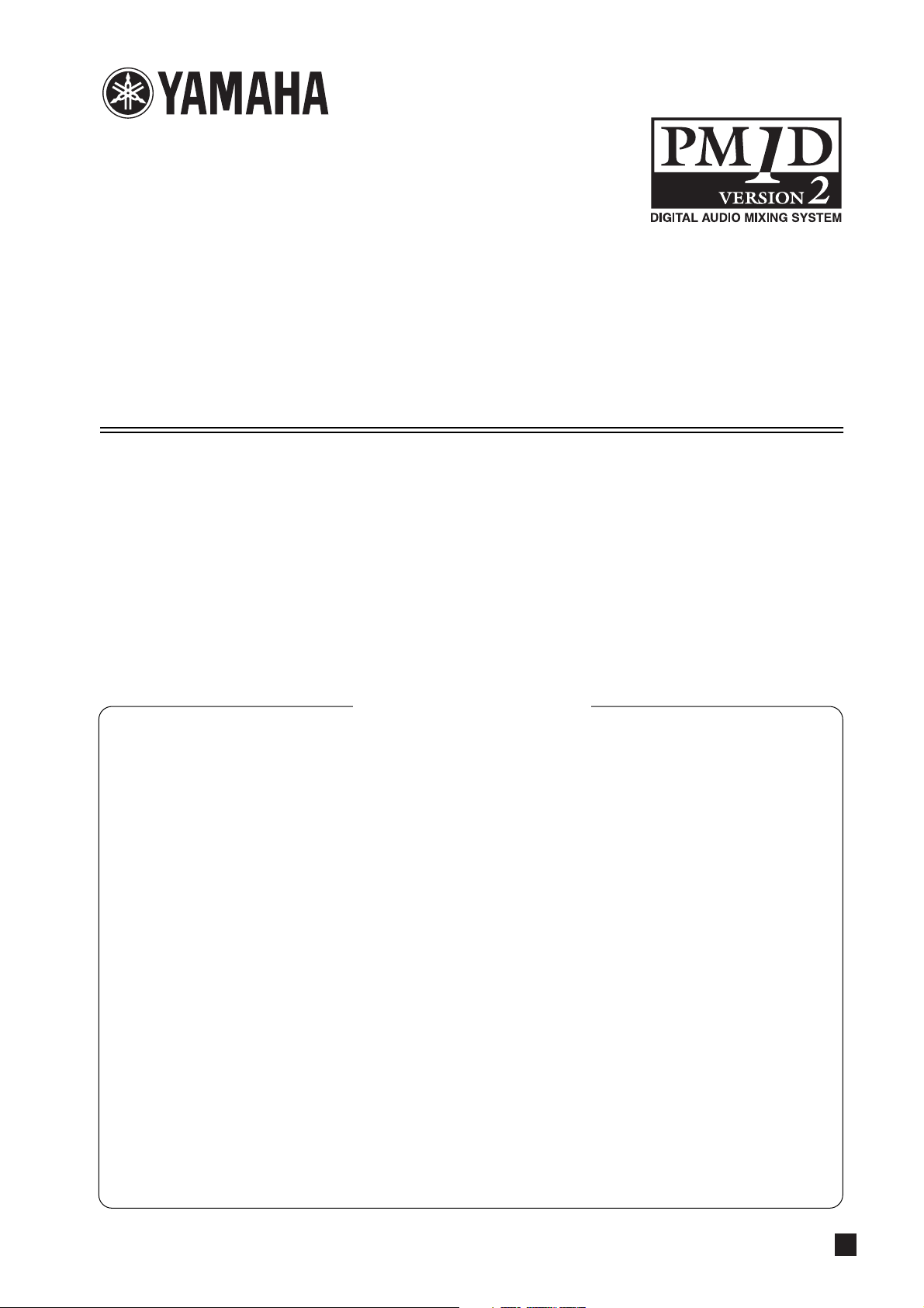
Auto Gain Adjustment function
If you adjust the HA gain on the master CS1D (master for HA
control), the attenuation on a slave CS1D can automatically be
adjusted so that the channel output levels will remain
unchanged.
Engine
DSP1D/
DSP1D-EX
Output B
AI8 (ID=1)
Output A
Engine
DSP1D/
DSP1D-EX
ANALOG OUTPUT BOX
CONTROL
PORT
A
B
C
The master unit is the CS1D (or PM1D Manager) connected
via a DSP1D that is connected to the port through which the
AI8 is controlled. The slave unit is the CS1D (or PM1D Manager) connected via a DSP1D that is connected to any port
other than the master. You can switch between the master and
slave.
Slave
Console CS1D
Master
Console CS1D
2. In the upper left of the screen, click the AUTO
GAIN ADJUSTMENT button to enable the function.
The Auto Gain Adjustment function is now enabled.
3. Turn the GAIN ADJ button on or off to switch the
function for each channel on or off.
Note
• Click the SET ALL button to turn on the function for all channels
globally. Click the CLEAR ALL button to turn off the function for
all channels globally.
• In most cases, turn on the Auto Gain Adjustment function only on
the slave CS1D unit. If you turn on the function on the master
CS1D unit, the output level of the master CS1D will also be
adjusted automatically.
• The GAIN ADJ button’s on/off status is not linked even if the cor-
responding two channels are paired. Even if the GAIN ADJ button of either one of the paired channels is turned on, the
attenuators will not be linked.
• When you turn off the GAIN ADJ button for one of the paired
channels, the attenuator value for the even-numbered channel
will change to the value for the odd-numbered channel. In this
case, please note that the volume level might increase more than
expected.
• If the attenuator values are selected as one of the Recall Safe
items, and if the GAIN ADJ button for the recalled scene is set to
on, this function will apply to the recalled HA gain. The Recall
Safe function does not apply to the GAIN ADJ button and AUTO
GAIN ADJUSTMENT button settings. Therefore, you must first
store these button settings in the scenes.
PM1D Manager Remote Control function
■ Switching the Auto Gain Adjustment
function on and off
1. On the slave CS1D, display the ATT screen for the
IN EQ function.
AUTO GAIN ADJUSTMENT button
SET ALL and CLEAR ALL buttons
ATT
GAIN ADJ buttons
2 Main changes
Connecting the PM1D Manager and a Yamaha digital mixing
console (DM2000, 02R96, or DM1000) via USB enables you to
remotely control the PM1D system from the digital mixing
console. For details, refer to the PM1D Manager V2 Owner's
Manual.
Yamaha digital mixer
(DM2000 V2, 02R96 V2,
DM1000 V2)
USB
PM1D system
Engine
DSP1D/DSP1D-EX
PM1D Manager
USB/RS232C
Console CS1D
Page 3
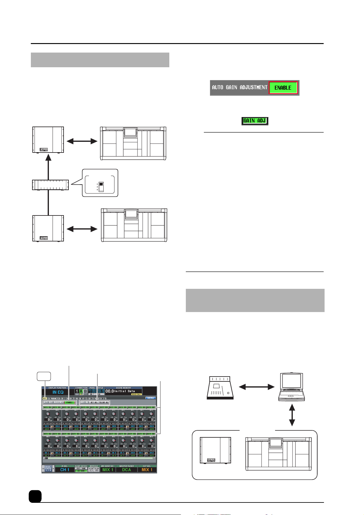
VCM Effects available
Va r ious effects sold as Add-On Effects packages for Yamaha
digital mixing consoles (such as DM2000) are now included as
standard. To use the VCM effects, you must first specify the
number of VCM effects you wish to use to limit the number of
available GEQ modules.
EFFECT
The VCM effects employ Virtual Circuitry Modeling technology, and include compressors and EQs that model the characteristics of analog circuits, OpenDeck, which emulates tape
compression created by open reel tapes; and the REV-X reverb
effect, which is based on a newly-developed algorithm and
provides richly reverberant sound quality with smooth attenuation. For more information on the VCM effects, please refer
to the Appendix on page 18.
To use the VCM effects, you must first specify the number of
VCM effects you wish to use in the following DSP CONFIG
screen to limit the number of available GEQ modules.
DSP CONFIG
Value VCM effects
——EFFECT 1–8 GEQ 1–24
1 EFFECT 1 EFFECT 2–8 GEQ 1–22
1-2 EFFECT 1–2 EFFECT 3–8 GEQ 1–20
1-3 EFFECT 1–3 EFFECT 4–8 GEQ 1–18
1-4 EFFECT 1–4 EFFECT 5–8 GEQ 1–16
1-5 EFFECT 1–5 EFFECT 6–8 GEQ 1–14
1-6 EFFECT 1–6 EFFECT 7–8 GEQ 1–12
1-7 EFFECT 1–7 EFFECT 8 GEQ 1–10
1-8 EFFECT 1–8 — GEQ 1–8
Conventional
effects
Available GEQ
Note
• To use VCM effects on a single effect module, you must
disable two GEQ modules.
• If you change this setting, the effect and GEQ output will be temporarily muted.
• The disabled GEQ modules still enable you to control the parameters, but the output will be muted.
• You can recall these new effects in the same way as the existing
effects. That is, you recall the desired effects from the Effect
library.
• Please note that if you mix a signal processed with VCM effects
with a signal that utilizes a different routing, a difference in time
resulting from the different signal paths may cause a comb filter
effect (a phenomena in which the level of some frequencies
decreases).
Channel Move function in the CH
COPY screen
In addition to the CH Copy function in the CH COPY screen,
which copies channels globally, a CH Move function that
moves channels is now available.
CH MOVE button
CH COPY
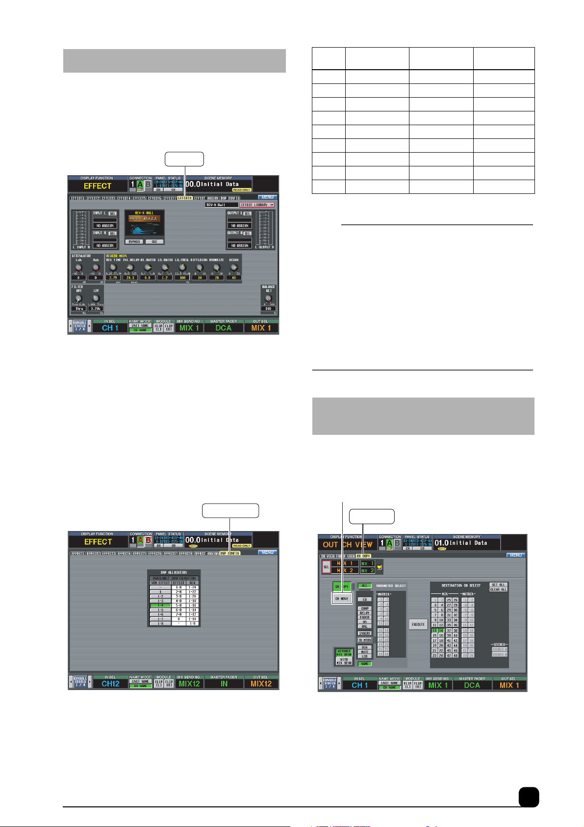
The CH Move function enables you to move any input or output channels to specified channel locations. When the channels
are moved, the channels between the move source and destination channels will move forward or backward accordingly. To
use the CH Move function, you can either use the CH COPY
screen or operate the keys on the top panel.
Main changes 3
Page 4
■ Moving the channels in the CH COPY
screen
1. Display the CH COPY screen for the IN CH View or
OUT CH View function.
CH MOVE button
CH COPY
■ Moving the channels from the top panel
1. Press the [SEL] switches to select the input channels you wish to move.
2. Press the [CHANNEL COPY] key.
3. Hold down the [SHIFT] key and press the [SEL]
switch of the destination channels.
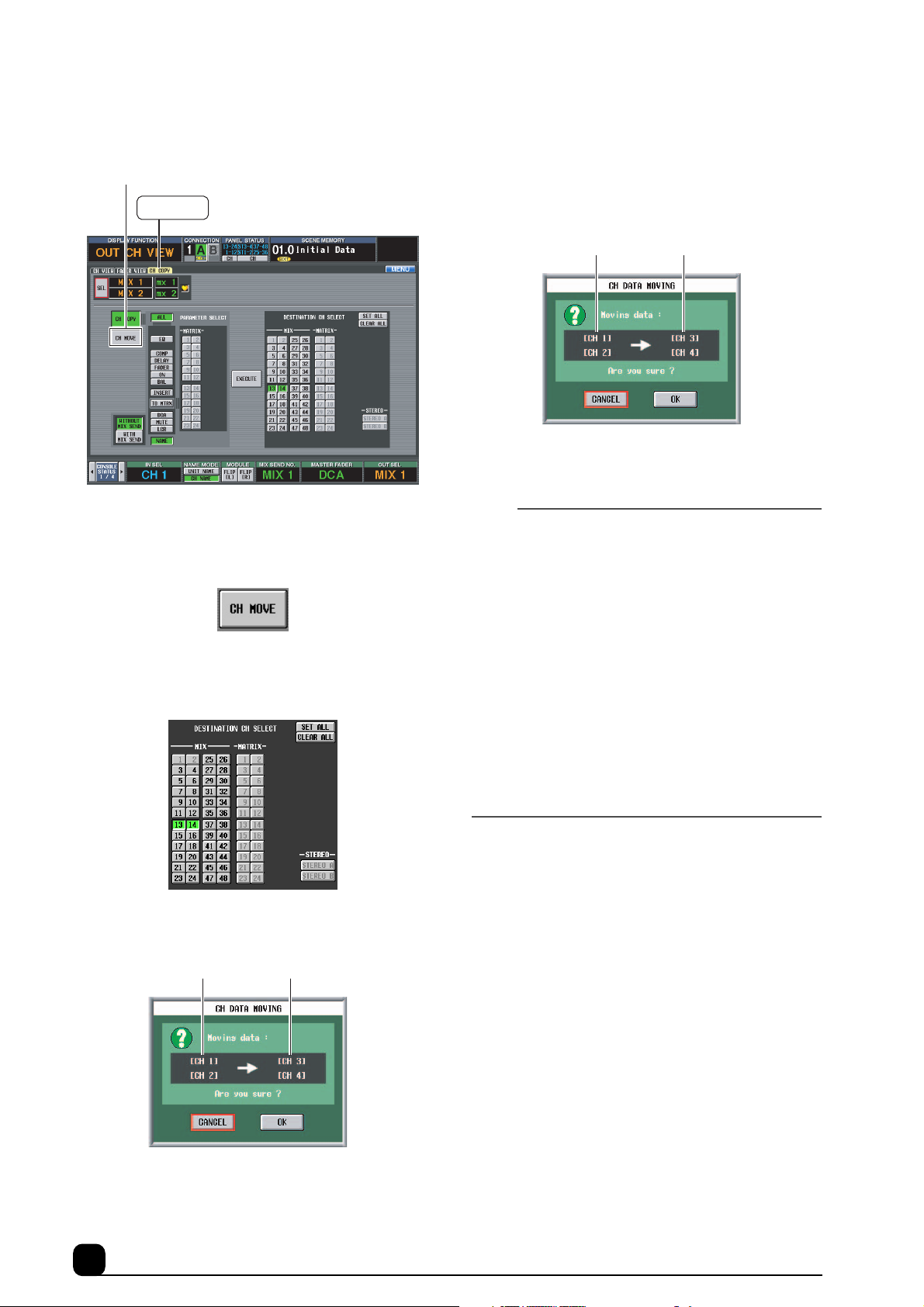
The CH DATA MOVING pop-up window appears, indicating the move source and destination channel numbers.
Move source channels Move destination channels
4. Click the OK button to execute the function.
The channels are now moved to the new locations.
2. In the CH COPY/CH MOVE section, turn on the
CH MOVE button.
If the CH COPY button is on, you can use the usual Channel Copy function.
3. Press the [SEL] switches to select the channels you
wish to move.
4. Select the destination channels in the DESTINATION CH SELECT section.
5. Click the EXECUTE button.
The CH DATA MOVING pop-up window appears, indicating the move source and destination channel numbers.
Move source channels Move destination channels
Note
• The move source channel can be a single channel or two
channels that can be paired.
• You can move a single channel under the following conditions:
There are no paired channels between the move source and
destination channels, AND all the following parameters are
turned off: HA GAIN GANG, HA A/B LINK, GATE LINK, COMP
LINK, DELAY GANG, GANG PAN/INV PAN/BALANCE in PAN
MODE, and M/S DECODE.
• If you move two channels, the first channel of the destination
channels will be the first of the two channels that can be paired.
Therefore, moving two channels will never swap between the left
and right channels.
• You can move the channels only within the following channel
sections:
– Input channels 1–96
– Stereo input channels 1–8
– MIX channels 1–48
– STEREO A/B channels
–MATRIX channels 1–24
6. Click the OK button to execute the function.
The channels are now moved to the new locations.
4 Main changes
Page 5

Changes in Scene Memories and Libraries
2 EVENT TRIGGER
Expanding the Event Recall function in
the TC EVENT screen
In the TC EVENT screen, you can now register scenes in the
order of use, so that these scenes can be recalled manually, or
automatically according to the specified interval time.
TC EVENT
1
3
2
The TC EVENT screen features the following additional functions:
1 EVENT RECALLING
Use the following three buttons to switch the event list
operation.
Button function
DISABLE
ENABLE
[ALL MANUAL]
ENABLE
The upper part of the display will show indica-
tor if ENABLE [ALL MANUAL] is selected, or
indicator if ENABLE is selected.
The Event List function will not recall
scenes registered in the event list.
Scenes registered in the event list will
be recalled only by manual operation. If
the list contains events for which a time
code has been specified, the candidate
event for recall will change as time
code progresses, but events will not
actually be recalled unless you recall
them manually.
Scenes registered in the event list will
be recalled according to the specified
condition (time code, interval, or manual operation).
4
5
This column indicates the way in which each event is
recalled.
Click the button to display the TC EVENT pop-up
window, then click one of the following three buttons to
select the recall condition.
Button function
You can use the EVENT RECALL button
MANUAL
INTERVAL
TIME CODE
Event that is recalled when the specified time has
elapsed since the preceding scene was recalled
Event that will be recalled manually
in the EVENT RECALL section (4) or a
USER DEFINE switch to recall the event.
“[MANUAL]” appears in the EVENT TRIGGER column.
The scene will be recalled when the specified time has elapsed since the preceding
scene was recalled. If you select this button, specify the INTERVAL TIME parameter in the range of 0.1 through 999.9sec.
An “ ” symbol and the interval time will
appear in the EVENT TRIGGER column
of the event list.
The scene will be recalled when the time
code (LTC or internal time code) reaches
the specified time. If you select this button, specify the time code (hours/minutes/
seconds/frames). The specified time code
will appear in the EVENT TRIGGER column of the event list.
Events that will be recalled when the time
code reaches the specified time
Changes in Scene Memories and Libraries 5
Page 6

3 SCENE MEMORY
These are the number and title of the scene to be recalled.
Click the button to display the TC EVENT pop-up
window, then click the number of a scene to select it.
Button Function
DIRECT
INC
DEC
DISABLE
Recalls the specified scene. Specify a
scene to recall in the section to the
right.
Recalls the subsequent scene (registered just after the current scene).
Recalls the previous scene (registered
just before the current scene).
Recalls no scene.
Overwriting libraries during the Auto
Store operation
When you store scenes using the Auto Store function, you can
now select an unused library or the original library as the initial store destination.
DEFAULT EDIT LIBRARY NO.
The following buttons are now available in the SCENE STORE
pop-up window that is displayed when you press the SCENE
MEMORY [STORE] switch (or the STORE button in the
MEMORY screen).
4 EVENT RECALL
These functions enable you to recall events. The following
three buttons are provided.
Button Function
PREV
DIRECT
NEXT
When you click this button, the event preceding the last-recalled event in the list
will be recalled and selected.
When you click this button, the event currently selected in the event list will be
recalled.
When you click this button, the event fol-
lowing the last-recalled event in the list
will be recalled and selected. This button
is useful when you recall an event that
has been assigned as “[MANUAL]” in the
EVENT TRIGGER column.
5 MOVE UP/MOVE DOWN
These buttons move the currently-selected event one position earlier (MOVE UP) or later (MOVE DOWN) in the
event list.
Note
• If the EVENT TRIGGER column of the selected event shows a
time code, these buttons will be grayed-out and unavailable. To
change the order of each event that displays a time code,
change the time code.
DEFAULT EDIT LIBRARY NO.
NEW
OVERWRITE
The lowest unused library numbers will be
selected. (This is the same as the previous software version.)
The number of the most-recently recalled
library will be selected. (If the scene was
specified as read-only, or if the corresponding library is write-protected, the
lowest-numbered unused library will be
selected.) This selection is useful when
you wish to prevent a particular library
from becoming full or lacking space during the Auto Store operation, or when you
wish to edit a particular library.
Note
• This setting is remembered when you close the pop-up
window.
6 Changes in Scene Memories and Libraries
Page 7

Unit settings can be included in the
Recall Safe channel settings
You can globally apply the Recall Safe function to settings for
units that are patched to Recall Safe channels, as well as to the
Recall Safe channel settings themselves.
SAFE KEY MODE SELECT section
RECALL SAFE
Additional preset scenes
Factory-shipped preset scenes 00.0 – 00.9 in the scene memory
were reviewed and replaced with more practical scenes. For
details, please refer to the “Scene Memory Preset List” on
page 15.
Hint
• To use the preset scenes, follow the steps below:
1. Recall the desired preset scene.
2. In the INPUT PATCH screen, patch the input channels that
use the signals from the connected units. When you click the
AUTO SETUP button, the unit signals are patched from
Channel 1 in the order of the connected units.
3. In the OUTPUT PATCH screen, patch the buses to the signals of the connected units.
Note
• Please note that if you mix signals that have different paths, a
difference in the time taken via the different signal paths may
cause a comb filter effect (a phenomena in which the level of
some frequencies decreases).
Expanded user area for Input EQ/
Channel libraries
SAFE KEY MODE SELECT
If you turn on or off the Recall Safe function for the selected channel from the
CH
CH+UNIT
panel or in the IN CH VIEW screen, only
the Recall Safe function for the channel is
turned on or off. (This is the same as the
previous software version.)
If you turn on or off the Recall Safe function for the selected channel from the
panel or in the IN CH VIEW screen, the
Recall Safe function for both that channel
and the unit patched to the channel is
turned on or off.
Note
• Selecting the Recall Safe items using the SAFE [RECALL]
switch on the panel or the button in the IN CH VIEW screen
(when the CH+UNIT button is turned on) provides the same
result as turning on the SAFE ON/OFF button and UNIT button
on the screen (when the CH button is turned on).
• When the CH+UNIT button is turned on, the SAFE [RECALL]
switch on the panel or the button in the IN CH VIEW screen is
linked to the on/off operation of the SAFE ON/OFF and UNIT
buttons on the screen.
The user area for the Input EQ library and Input Channel
libraries has been expanded.
•Input EQ library
#001 – 199 (#038 – 199 are the user area.)
•Input Channel library
#000 – 199 (#001 – 199 are the user area.)
Changes in Scene Memories and Libraries 7
Page 8

Changes and additions of screens
New FADER VIEW screen
The FADER VIEW screen has been added to the IN CH View
function and OUT CH View function.
FADER VIEW
1
2
3
1
2
3
1 ON/MUTE
These buttons enable you to switch the channels on/off,
and switch DCA group muting on/off. They are linked to
the [ON] switches of the corresponding channels and the
[MUTE] switches of the DCA groups.
4
Clock on the meter bridge
The TIME CODE indicator on the meter bridge block can now
display the current time. Also, an additional parameter enables
you to switch between the current time and time code.
PREFERENCE
TIME CODE DISPLAY section
2 Level
These buttons enable you to adjust the level of the channels
and DCA groups. The current value is shown in the box
immediately below. They are linked to the encoder or fader
of the corresponding channel or DCA group.
3 CUE
These buttons enable you to switch cue monitoring on/off
for the channels and DCA groups. They are linked with the
[CUE] key of the corresponding channel or DCA group.
4 DISPLAY CH
Switches the channels that are shown in the FADER VIEW
screen.
• When you are using the IN CH View function:
INPUT [PANEL]
CH 1-48/ST IN 1-4
CH 49-96/ST IN 5-8
• When you are using the OUT CH View function:
MIX 1-48
MATRIX
Channels specified via the Panel
Assign function, and DCA groups
1–12
Input channels 1–48, ST IN channels 1–4, DCA group 1–12
Input channels 49–96, ST IN
channel 5–8, DCA groups 1–12
MIX channels 1–48, STEREO A/
B channels, DCA groups 1–12
MATRIX channels 1–24, STEREO A/B channels, DCA groups
1–12
TIME CODE DISPLAY
PRESENT TIME
TIME CODE
Displays the current time in 24-hour format (hours/minutes/seconds).
Displays the time code.
Displaying the GEQ routings
When you select a GEQ module in the GEQ PARAMETER
screen, the GEQ SELECT pop-up window enables you to identify any GEQ modules that have already been patched.
This window displays the signal routing of already-patched
GEQ modules, and displays “NO ASSIGN” for unpatched
GEQ modules.
8 Changes and additions of screens
Page 9

Displaying the GR meters
The INPUT GR screen and OUTPUT GR screen have been
added to the Meter function. These screens display the gain
reduction meters for Input channel gates and compressors, and
Output channel compressors.
INPUT GR OUTPUT GR
1
3
2
4
3
1 DISPLAY CH
Switches the channels that are displayed in the INPUT GR
and OUTPUT GR screens.
INPUT GR screen:
4 Pair icon
This icon indicates the pairing status of two adjacent oddnumbered/even-numbered channels.
CH 1-48/ST IN 1-4
CH 49-96/ST IN 5-8
Input channels 1–48,
ST IN channels 1–4
Input channels 49–96,
ST IN channels 5–8
OUTPUT GR screen:
MIX 1-48
MATRIX 1-24/STEREO
MIX channels 1–48
MATRIX channels 1–24,
STEREO A/B channels
2 GATE/COMP (Gate/Compressor)
These buttons select whether the meters will display gain
reduction for the Gate or Compressor. These buttons
appear only in the INPUT GR screen.
3 Meters
These peak level meters indicate the amount of gain reduction for each channel. The current fader value is shown in
the box below.
Changes and additions of screens 9
Page 10

Other changes
Filtering during save or load operations
You can specifically select any region of any scene or library
data to be saved to a memory card. You can also specifically
select any region of any scene or library data to be loaded from
a memory card.
LOAD/SAVE
be saved or loaded. If you want to change the save/load
destination numbers, click the [ ]/[ ] buttons at the
left and right of the starting number box or use the [DATA]
encoder. (The value in the ending number box will change
automatically according to the starting number and the
source range.)
When you change the save destination starting number:
1
2
3
4
In addition to BASIC mode (in which you can save the entire or
specified data in the scene memories or libraries to a memory
card, or load them from a memory card), ADVANCED mode
enables you to save or load a specified range of the data.
■ ADVANCED mode:
When you turn on the ADVANCED button in the LOAD/SAVE
screen, the left side of the screen will display the following
items:
1 MODE
Switches between BASIC and ADVANCED mode.
2 CATEGORY
Indicates the category of data that is selected for saving or
loading: scene memory or a type of library. Click the [ ]/
[] buttons at left and right or use the [DATA] encoder to
change the category.
3 SOURCE (save/load source numbers)
CS1D
Memory card
AAA
Starting
number
Ending
number
When you change the load destination starting number:
Starting
number
Ending
number
01.0
BBB
01.1
CCC
01.2
DDD
01.3
EEE
01.4
FFF
01.5
SOURCE DESTINATION
Memory card
BBB
02.1
CCC
02.2
DDD
02.3
EEE
02.4
FFF
02.5
SOURCE
Starting
number
SAVE
Starting
number
LOAD
02.0
02.1
02.2
02.3
02.4
02.5
02.6
02.7
02.8
DESTINATION
AAA
BBB
CCC
DDD
EEE
CS1D
BBB
CCC
DDD
EEE
Note
• To format a memory card first, use a computer or other external
device and select the FAT16 format. The CS1D does not
support the FAT 32 format.
• You can load the data you saved using System Software older
than version 2.0.
• The preset effects in the Effects library of System Software version 2.0 includes VCM effects. Therefore, if you try to load the
Effects library data of an older version, part of the data may not
be loaded. In such a case, change the load destination starting
number in the DESTINATION section, then load the data again.
Indicates the starting and ending numbers of the scene
memory or library items that will be saved to or loaded
from the card. Click the [ ]/[ ] buttons at the left and
right in each box or use the [DATA] encoder to change the
numbers.
4 DESTINATION (save/load destination num-
bers)
Indicates the starting and ending numbers of the scene
memory or library items into which the specified data will
10 Other changes
■ BASIC mode:
In BASIC mode, you can now specify the range of data to be
saved or loaded for the Unit library, Patch library, and Name
library.
Page 11

Direct output just before the HPF
The signal can be now directly output just before the Input
channel HPF. You can also adjust the direct output level.
INSERT/DIRECT POINT
DIRECT OUT POINT column
PRE HPF buttonDIRECT OUT LEVEL column
To select a position just before the HPF as the direct output on
the INSERT/DIRECT POINT screen, turn on the PRE HPF
button for the corresponding channels in the DIRECT OUT
POINT column. The DIRECT OUT LEVEL column will indicate the direct output levels. However, to adjust the level, use
the INSERT/DIRECT VIEW screen.
DIRECT button LEVEL knob
To select a position just before the HPF as the direct output in
the INSERT/DIRECT VIEW screen, turn on the DIRECT button located just before the HPF. Use the LEVEL knob located in
the lower right corner of the screen to change the direct output
level. The direct output levels are not linked even if the corresponding two channels are paired.
Hint
• These settings are saved in scene memories.
• If you load data that was saved in a System Software version
older than version 2.0, the direct output level will be set to 0 dB.
The default direct output point is PRE EQ.
INSERT/DIRECT VIEW
Additional functions for the USER
DEFINE switches
More functions are available that can be assigned to the USER
DEFINED [1]–[8] switches.
USER DEFINE
The following functions have been added:
FUNCTION PARAMETER Explanation
GEQ SELECT
TAP TEMPO*
TC EVENT
TALKBACK
DIRECT
ASSIGN
* This function is enabled only when an effect that features the TEMPO
parameter is selected. The USER DEFINE switch LED flashes at the
specified tempo while and after you set the tempo. For more information
on the Tap Tempo function, please refer to page 51 of the PM1D System
Software Version 1.5 Supplementary Manual.
GEQ1–24
CURRENT
EFFECT1–8
NEXT EVENT
RECALL
PREV EVENT
RECALL
DIRECT EVENT
RECALL
ENABLE/DISABLE
ENABLE[ALL
MANUAL]/DISABLE
MIX 1–48,
MATRIX 1–24,
STEREO,
MONITOR B
Display the GEQ PARAMETER screen.
Uses the Tap Tempo function available on the displayed screen.
Uses the Tap Tempo function available for the
specified effect.
Recalls the subsequently-numbered event.
Recalls the previouslynumbered event.
Recalls the specified
event registered on the
TC EVENT screen.
Switches between the
ENABLE button and DISABLE button on the TC
EVENT screen.
Switches between the
ENABLE [ALL MANUAL]
button and DISABLE button on the TC EVENT
screen.
Send the talkback signal
to the specified output
channels. (If you turn it
off, the previous talkback
setting will be used.)
Other changes 11
 Loading...