

Page 1
Yamaha Virtual Acoustic Plug-in Board
Yamaha Virtual Acoustic Plug-in Board
Carte Plug-in de Synthèse Acoustique Virtuelle
Owner’s Manual
Bedienungsanleitung
Mode d’emploi
Page 2
Precautions
● Do not expose the daughter board to direct sunlight,
excessive humidity, high temperatures, excessive dust
or strong vibrations.
● Before handling the daughter board, be sure to touch a
metal surface to discharge any static electricity which
may be in your body.
● When holding the daughter board, do not touch the in-
side area of the circuit board or apply excessive pressure to the board, and be sure to protect the board from
● Before connecting the computer to other devices, turn
off the power switches of all devices.
● Y amaha is not responsible for loss of data through com-
puter malfunctions or operator actions.
● The daughter board contains no user-serviceable parts,
so never touch the inside area of the circuit board or
tamper with the electronic circuitry in any way. Doing
so may result in electrical shock or damage to the daughter board.
contact with water or other liquids.
● Before installing the daughter board onto a sound card,
unplug the power connector of your computer.
* The company names and product names in this Owner’s Manual are the trademarks or registered
trademarks of their respective companies.
* The screens as illustrated in this owner’s manual are for instructional purposes only, and may ap-
pear somewhat different from the ones of your instrument.
FCC INFORMATION (U.S.A.)
1. IMPORTANT NOTICE: DO NOT MODIFY THIS UNIT!
This product, when installed as indicated in the instructions contained in this manual, meets FCC requirements. Modifications
not expressly approved by Yamaha may void your authority, granted by the FCC, to use the product.
2. IMPORTANT: When connecting this product to accessories and/or another product use only high quality shielded cables.
Cable/s supplied with this product MUST be used. Follow all installation instructions. Failure to follow instructions could void
your FCC authorization to use this product in the USA.
3. NOTE: This product has been tested and found to comply with the requirements listed in FCC Regulations, Part 15 for Class
”B” digital devices. Compliance with these requirements provides a reasonable level of assurance that your use of this product
in a residential environment will not result in harmful interference with other electronic devices. This equipment generates/
uses radio frequencies and, if not installed and used according to the instructions found in the users manual, may cause
interference harmful to the operation of other electronic devices. Compliance with FCC regulations does not guarantee that
interference will not occur in all installations. If this product is found to be the source of interference, which can be determined
by turning the unit ”OFF” and ”ON”, please try to eliminate the problem by using one of the following measures:
Relocate either this product or the device that is being affected by the interference.
Utilize power outlets that are on different branch (circuit breaker or fuse) circuits or install AC line filter/s.
In the case of radio or TV interference, relocate/reorient the antenna. If the antenna lead-in is 300 ohm ribbon lead, change
the lead-in to co-axial type cable.
If these corrective measures do not produce satisfactory results, please contact the local retailer authorized to distribute this
type of product. If you can not locate the appropriate, please contact Yamaha Corporation of America, Electronic Service
Division, 6600 Orangethorpe Ave, Buena Park, CA 90620
Y AMAHA CANNO T BE HELD RESPONSIBLE
FOR DAMAGE CAUSED BY IMPROPER
CARE AND USE OF THE D AUGHTER BO ARD.
* This applies only to products distributed by YAMAHA CORPORATION OF AMERICA.
CANADA
This Class B digital apparatus complies with Canadian ICES-003.
Cet appareil numérique de la classe B est conforme à la norme NMB-003 du Canada.
• This applies only to products distributed by Yamaha Canada Music Ltd.
• Ceci ne s’applique qu’aux produits distribués par Yamaha Canada Musique Ltée.
2
Page 3
Introduction
Virtual Acoustic Plug-in Board PLG100-VL will expand your tone generator/ sound card such
as MU100 and SW1000XG by adding 256 VL voices created by the unique Virtual Acoustic
Synthesis (including 137 VL-XG, XG compatible, voices). Using the included software, VL
Visual Editor, you can edit VL voices and create your own voices from scratch.
Please read through this manual to take full advantage of the PLG100-VL before use and keep
the manual in a safe place for future reference.
ENGLISH
ENGLISH
Contents
About PLG100-VL ........................................................4
Virtual Acoustic Synthesis ............................................6
Creating Voices ............................................................ 10
Voice Organization ...................................................... 10
Selecting Voices............................................................12
Editing VL Voice Part Parameters ............................15
VL System Parameters................................................24
Appendix Q & A ....................................................... 28
Voice List ................................................. 30
MIDI Data Format..................................34
MIDI Implementation Chart ................. 46
About XG Plug-in System
With Yamaha XG Plug-in System you can expand your tone generation system by
simply mounting an optional board onto the “mother” tone generator/sound card. For
example, you will be able to use extra voices from a different sound synthesis such as
Virtual Acoustic Synthesis, apply completely new dimensional facet of effects to your
music and/or add the latest technology to your music.
About Sondius XG
Products bearing the SONDIUS-XG logo are licensed under patents of Stanford University and Yamaha as listed on the internet web site, <http://www.sondius-xg.com>.
About VL-XG
The VL Extension for XG (“VL Extension for XG” is abbreviated to VL-XG) included in the PLG100-VL significantly enhances and expands the musical capabilities of the XG format with the superior sound and expressive potential of Yamaha
Virtual Acoustic Synthesis. The PLG100-VL provides superior wind and string instrument voices while the XG tone generator/sound card supplies drums, percussion,
keyboard, and other voices.
3
Page 4

About PLG100-VL
Main Features
● Allows you to play back the songs which are programmed with the VL-XG voice data
(p.10).
● Lets you edit the VL parameters on the tone generator (a model with LCD screen)
(p.15).
● Allows you to simulate an acoustic musical instrument and create a “virtual” musical
instrument by using the “VL Visual Editor,” a plug-in software for the “XGworks,”
even if you don’t have further musical knowledge (p.10).
● Allows you to play the PLG100-VL by WX5 (via BT7) connected to the tone genera-
tor via MIDI (p.27).
● Lets you easily install the PLG100-VL onto the tone generator/sound card.
VL Voice Edit
Editing VL-XG Voices
If you want to edit the existing MIDI files or create a MIDI song using various VL-XG
voices from the PLG100-VL, you need to use a sequencing software which is capable of
editing the system exclusive messages and transmit bank select/program change messages
and/or parameter changes to the PLG100-VL. See MIDI Data Format (p.34) for more
information on the system exclusive messages.
However, using the XG Editor Window of the included music sequencing software,
“XGworks” or “XGworks lite” (a Windows application, provided in the included CDROM) lets you visually and easily enter the VL program change data and edit its data
instead of inputting rather complicated system exclusive messages.
Creating Your Own VL Voices
Even if you have no experience in voice creation, the “VL Visual Editor” (also provided in
the included CD-ROM) lets you easily create VL voices. The “VL Visual Editor” is one of
the plug-in software for the “XGworks” (P.10).
• To use the “XGworks” and “VL Visual Editor” you need to connect the “mother” tone generator/sound card
to your PC, and properly set the “Driver” and “Input/Output devices.” For the details refer to the owner’s
manual of the “XGworks.”
4
Page 5
About PLG100-VL
■ Installation
For the installation of the PLG100-VL see the manual of respective “mother” tone generator/sound
card.
■ Included Items
• PLG100-VL Board
• CD-ROM
• Owner’s Manual
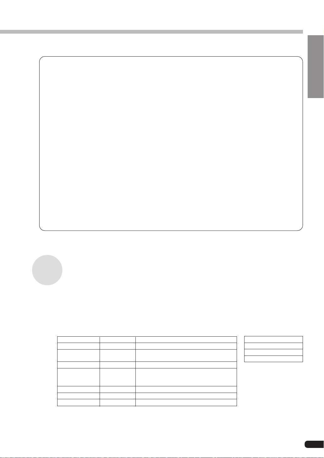
■ Specifications
Tone Generator S/VA
(Self-oscillating Virtual Acoustic Synthesis: VLR Algorithm)
Polyphony 1 note monophonic (latest note priority)
Sound Module Mode VL-XG
Interface XG Plug-in Connector (15-pin Digital Connector)
Number of Voices 256 Preset voices (including 137 VL-XG voices)
6 Custom voices
64 Internal voices
Dimensions 138.5mm(W) 89mm(D) 8.5mm(H)
Weight 56g
ENGLISH
About the Demonstration Data Provided in the CD-ROM
The demonstration data, songs and performances, provided in the included CD-ROM will
give you an idea of some of the PLG100-VL’s capability. Try them all using the “XGworks.”
* Performance data: send them as the bulk data to the XG tone generator using the “XGworks.”
● Songs
File Name Song Name Composer
COOLJIVA.MID Cool JiVA Katsunori Ujiie
OXYGEN.MID Oxygen Andy Mowat
NOBODY.MID Nobody Knows Akio Suzuki
SILHOUET.MID Silhouettes Tom Scott (GRP Recording Artist)
VAMBIENT.MID VAmbient Katsunori Ujiie
DOGROOVA.MID Do GrooVA Katsunori Ujiie
CLOUDS.MID Clouds Akio Suzuki
Daniel Powell (YAHAMA R&D London)
Nate Tschetter
Charles Feilding
(YAMAHA Sound Design Office)
● Performances
VLPFM1.MID
VLPFM2.MID
VLPFM3.MID
VLPFM4.MID
5
Page 6
Virtual Acoustic Synthesis
Unlike previous tone generation systems which use oscillators, function generators, preset waveforms or samples to produce sound, Yamaha Virtual Acoustic (“VA”) Synthesis applies sophisticated computer-based “physical modeling” technology to musical sound synthesis. In the same
way that computer “models” are used to simulate weather systems or the flight characteristics of
aircraft in the design stage, the PLG100-VL simulates the very complex vibrations, resonances,
reflections and other acoustic phenomena that occur in a real wind or string instrument.
VA Advantages
The PLG100-VL offers many advantages in terms of musical performance. Not just in
terms of sound, but also in terms of the “behavior” that makes acoustic instruments so
… well, musical! Yamaha Virtual Acoustic Synthesis is simply the most musical tone
generation system ever created.
• The PLG100-VL sounds better, has more depth, and is more realistic in the musical
sense than any other tone generation system.
• Simply playing a note in the same way does not always produce precisely the same
sound. The instrument is responsive and “alive”.
• Note-to-note transitions have the same continuity exhibited by acoustic instruments.
What goes on in between the notes is just as important musically as the notes themselves.
• It has extraordinary expressive capability. Rather than simply controlling parameters
like volume or pitch, you can control characteristics such as breath and reed pressure
with appropriate complex effects on the timbre of the sound.
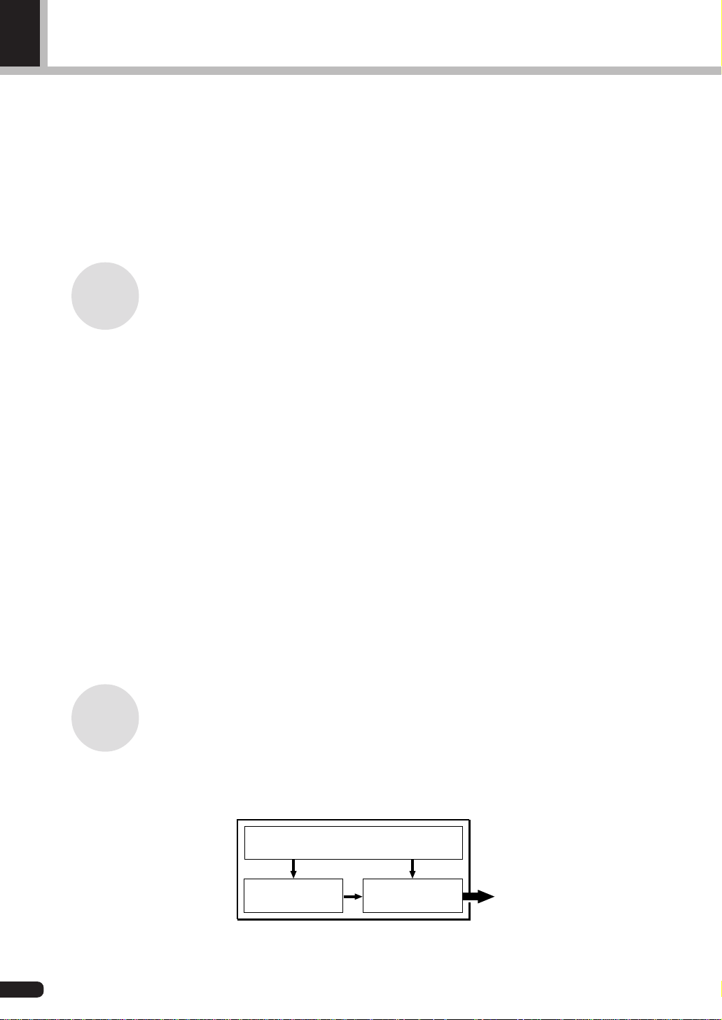
VL Tone Generator Model
The overall VL tone generation model or “algorithm” consists of three main blocks: the
instrument, controllers, and modifiers. In schematic form these blocks are arranged as
follows:
Controllers (also envelopes)
Instrument Modifiers
6
Sound out
Page 7
Virtual Acoustic Synthesis
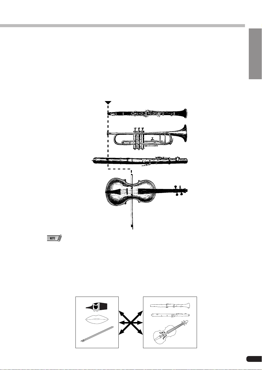
The Instrument
The key block in this algorithm is the instrument, since it is here that the fundamental tone
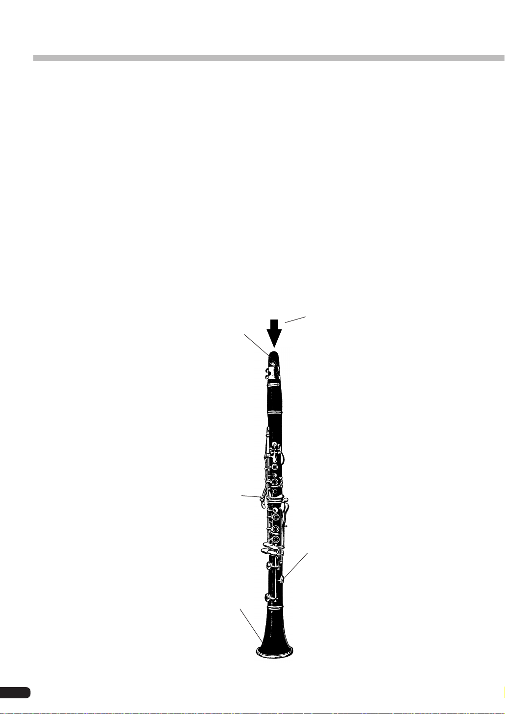
or “timbre” of the sound is defined. The instrument model consists primarily of a driver —
the reed/mouthpiece, lip/mouthpiece, or bow/string system — and a resonant system corresponding to the tube and air column or string.
In all these instruments pressure applied here (the
driving point) causes vibration which results in sound.
Reed vibration
Lip vibration
Air vibration
ENGLISH
String vibration
• The sound thus produced is amplified and sustained by the body of the instrument.
• The pitch of the sound is determined by the length of the air column or string, and the timbre is a complex
product of the driving source (reed, lip, air, string), the shape of the resonant cavity, the materials from
which the instrument is made, etc.
One of the remarkable features of the Virtual Acoustic Synthesis system is that just about
any driver can be used with any type of pipe or string.
Drivers
Pipes/String
7
Page 8
Virtual Acoustic Synthesis
The Controllers
The input to an acoustic wind instrument comes from the player’s lungs, trachea, oral cavity, and lips. In a string instrument it comes from the player’s arm movement, transmitted to
the string via a bow. These elements actually form an important part of the sound generating
system and, in the PLG100-VL, are included in the controllers block. The player also influences the sound of the instrument by playing the keys, tone holes, or frets, and this aspect of
control constitutes another part of the controllers block. These and other control parameters
provided by the PLG100-VL are listed in the illustration below.
In essence, the controller parameters determine how the instrument “plays”. All of these
parameters can be assigned to any external controller that can be used with the PLG100VL: breath controller, foot controller, modulation wheel, etc. The pressure parameter, for
example, will normally be assigned to a breath controller so the player can control the
dynamics of the instrument by varying the breath pressure applied to the controller — a
natural, instinctive way to play wind-instrument voices. At the same time the growl and
throat parameters might also be assigned to the breath controller in order to achieve life-like
response and effects.
Embouchure
The tightness of the lips against the reed
or against each other, or the force of the
bow against the string.
Tonguing
Simulates the half-tonguing technique
used by saxophone players by changing the “slit” of the reed.
Pitch
Changes the length of the air column or
string, and thereby the pitch of the sound.
Damping & Absorption
Simulate the effects of air friction in the
pipe or on the string, and of high-frequency losses at the end of the pipe or
string.
Throat
Controls the characteristics of the
“player’s” throat or bowing arm.
Pressure
The amount of breath pressure applied
to the reed or mouthpiece, or bow velocity applied to the string.
Growl
A periodic pressure (bow velocity) modulation which produces the “growl” effect
often heard in wind instruments.
Scream
Drives the entire system into chaotic
oscillation, creating effects that can only
be achieved with physical modelling
technology.
8
Page 9

Virtual Acoustic Synthesis
The Modifiers
The modifiers block consists of 4 sections as shown in the diagram. Although these may
appear to be simple effects, they are actually intimately related to the PLG100-VL’s soundproducing model and have a significant effect on the sound.
● Harmonic Enhancer
The Harmonic Enhancer determines the harmonic structure of the
sound to the extent that it can produce radical timbral variations within
an instrument “family” (e.g. saxes). Adjusting the Harmonic Enhancer
may not produce audible effects since many of the PLG100-VL voices’
harmonics are created without the Harmonic Enhancer.
Harmonic
Enhancer
Dynamic
Filter
ENGLISH
● Dynamic Filter
This section is similar to the dynamic filters found in many conven-
Frequency
Equalizer
tional synthesizers, with high-pass, bandpass, band elimination, and
low-pass modes. Some filter parameters are available via the PLG100VL controls, but the filter type cannot be changed.
• The degree how much the filter is applied can be changed using the key
scaling.
• The incline of the filters is -12dB/oct.
• This effect may vary depending on the selected voice.
Resonator
● Frequency Equalizer
The Equalizer boosts or decreases the output level around the designated frequency. The
PLG100-VL lets you access the equalizer function using “Low Gain (Bass)” and “High
Gain (Treble)” parameters.
● Resonator
The Resonator uses simulated “resonator” pipes or strings and delays to produce a “woody”
resonance effect — although it has little or no effect on some voices. The resonator parameters are not accessible but preset for some of the preset voices.
9
Page 10

Creating Voices
You can create VL voices using the VL Visual Editor, which is one of the plug-in applications
for the “XGworks” and provided in the included CD-ROM.
For the detailed information about the VL Visual Editor see the on-line manual of the VL Visual
Editor.
The VL voices created by the VL Visual Editor can be loaded to the Custom Voice Bank (p.11)
of the PLG100-VL and played back. However, the loaded data will be lost once you turn off the
“mother” tone generator/sound card. You need to load the data again if you want to use the
voices. You can save the VL voice data in a file as a part of the “XGworks” song data or in an
external MIDI data storage device such as MDF3 as a part of bulk data (voice file).
About XGworks Plug-in System
The software with this logo attached implies that it is one of the plug-in applications for
the sophisticated music sequencing software “XGworks” and “XGworks lite.” The
XGworks Plug-in System expands and enhances the power of the “XGworks” and
“XGworks lite.”
Voice Organization
The VL voices have each program number and are organized into 12 banks. For the voice list see
page 30.
• Banks 112 through 119: VL-XG Banks
These banks are used when the PLG100-VL functions as the VL-XG tone generator.
The voices from the PRESET 1 and PRESET 2 banks are assigned to MIDI banks and
program change numbers conforming to the Yamaha XG format.
• Since the PLG100-VL does not have a full set of XG-compatible voices, some voice numbers will be skipped
(e.g. 22, 23, 25, 27, etc.). If the truncated number is designated, the XG voice having the same program
number in the bank 1 will sound, instead.
10
• Bank 000: PRESET 1 (Pr1)
The PRESET 1 bank contains 128 preset voices which have been created primarily to be
played via a keyboard.
Page 11

Voice Organization
• Bank 001: PRESET 2 (Pr2)
The PRESET 2 bank contains 128 preset voices which have been created to provide maximum expressive capability when played with a breath controller or WX-series Wind MIDI
Controller.
• Bank 002: CUSTOM (Cst)
The CUSTOM bank has 6 memory locations (program numbers 001 - 006) in which you
can load the voices created by the Yamaha VL Visual Editor (p. 10).
The loaded voices cannot be backed up. When the “mother” tone generator/sound card is
turned off, the voices are reset to their defaults, the sound-effect type voices from the PRESET banks.
• Bank 003: INTERNAL (Int)
The INTERNAL voices of the VL70-m can be received and loaded (bulk data). The loaded
voices cannot be backed up. When the “mother” tone generator/sound card is turned off, the
voices are reset to their defaults, the voices from the PRESET banks, set up to be played via
a WX-series Wind MIDI Controller.
• The edited voices cannot be stored in the INTERNAL voice bank.
• (When using MU-series tone generator) Saving a performance containing a VL voice as a part records the
program number of the VL voice and the VL parameter settings edited on the “mother” tone generator.
• The VL-XG voices edited with XG Editor Window of the “XGworks” can be saved as a part of the song
data.
• Note that the “program numbers” here are 001–128 and the “MIDI program change numbers” are 000–
127. When selecting voices (programs) using an external MIDI device, subtract a value of “1” from the
“program numbers” to match the “MIDI program change numbers.”
ENGLISH
■ Selecting Banks ..........................................................................................
Use the MIDI bank MSB (control number 00) and LSB (control number 32) numbers listed
below to select VL banks from an external MIDI device.
BANK MSB LSB
BANK 112 97 or 81 112
BANK 113 97 or 81 113
BANK 114 97 or 81 114
BANK 115 97 or 81 115
BANK 116 97 or 81 116
BANK 117 97 or 81 117
BANK 118 97 or 81 118
BANK 119 97 or 81 119
PRESET 1 33 0
PRESET 2 33 1
CUSTOM 33 2
INTERNAL 33 3
11
Page 12

Selecting Voices
The VL voices can be selected as you do with the XG voices. However, you have to select XG
Mode or Performance Mode from the “mother” tone generator/sound card Sound Module Mode,
first. You also have to designate the Part, to which you want to assign the VL voice, in the Utility
sub-mode (PLUGIN).
• The sound cards like the SW1000XG do not include “Performance Mode.” Please check the owner’s manual of the
“mother” tone generator/sound card whether it include the Performance Mode, or not.
• The steps how to select a VL voice, set up the utilities and edit the VL part parameters shown below are explained
using the MU100. Therefore, the illustrations may be somewhat different from the LCDs of your instrument.
IMPORTANT
When you use a sound card or a tone generator with no panel buttons...
To select a VL voice, to set up the utilities and to edit the VL part parameters, you need to use a
sequencing software and transmit the MIDI messages such as XG System On, Bank Select MSB/
LSB, program change and parameter change to the “mother” sound card/tone generator, instead of
following the steps below.
Using the included “XGworks,” properly installed in your PC (which is connected to the sound card/
tone generator) allows you to access the VL-XG voices through the Voice List dialog of the “XGworks.”
■ Selecting VL Voice......................................................................................
1. Select XG or PERFORM from the “mother” tone generator Sound Module Mode.
When you select XG, Multi Play Mode will be engaged.
When you select PERFORM, Performance Play Mode will be engaged.
• The VL voices can be selected only when “normal” is selected in the Part Mode.
The VL voices can be played as a “part” in the XG Mode and as a “layer” in the Performance Mode.
2. Press SELECT button to place the cursor at the Bank Number.
3. Press VALUE button to select the Bank you want to use.
Depending on the Bank selected, 112–119 (VL-XG), 000 (Preset 1), 001 (Preset 2), 002
(Custom) or 003 (Internal) appears at the Bank Number location on the LCD.
When a VL voice is selected VL voice icon will be displayed on the LCD.
12
Page 13

Selecting Voices
• You may unintentionally select a bank number of the “mother” tone generator. Be sure to confirm that
the VL voice icon is displayed on the LCD.
4. Press SELECT button to place the cursor at the Program Number.
5. Press VALUE button to select the Program Number (voice) you want to use.
• If an invalid Program Change Number is selected while one of the VL-XG Banks (112–119) is chosen, VL
voice icon will be replaced with one of the XG voice icons.
■ Designating the Part for the VL Voice.......................................................
ENGLISH
1.
Press UTIL button to enter the Utility Mode.
2. Press SELECT button to place the cursor at PLUGIN.
3. Press ENTER.
The following display appears.
(If necessary) Press SELECT button to place the cursor at PLG100-VL.
4. Press ENTER.
The System Parameter Edit display exclusive to the PLG100-VL appears.
(If necessary) Press SELECT button to place the cursor at Part Assign.
13
Page 14

Selecting Voices
5. Press VALUE button to select the Part you want to use.
In the XG Mode: 01–16, off
In the Performance Mode: 01–04, off
When you use a sound card or a tone generator with no panel buttons...
To select a part for the VL voice you need to use a sequencing software and transmit the following
system exclusive message (part assign parameter) to the “mother” sound card/tone generator:
F0 43 1n 4C 70 nn ss pp F7 (Hexadecimal)
n : Device Number
nn : Plug-in Board Type (PLG100-VL is “00.”)
ss : Serial Number (which identifies the PLG boards when two same boards are installed)
pp : Part Number (to which the PLG100-VL is assigned)
• The VL voices cannot be assigned to several parts at the same time since the PLG100-VL is monophonic.
00 : for first PLG100-VL
01 : for second PLG100-VL
00 : Part 1
:
:
0F : Part 16
7F : off
14
Page 15

Editing VL Voice Part Parameters
The editings done to the parameters below affect all the voices. In other words the voices cannot
be individually edited. The parameter settings are effective even when you select a different
voice.
• The edited voices cannot be stored in the INTERNAL voice bank. Instead, the VL-XG voices edited using XG Editor
Window of the “XGworks” can be saved as a part of the song data.
1. Enter the Multi Part Edit Mode.
The sub-mode menu appears on the LCD.
2. Press SELECT button to place the cursor to PLUGIN.
3. Press ENTER.
The Part Parameter Edit display exclusive to the PLG100-VL appears.
ENGLISH
4. Press SELECT button to select the parameter you want to edit.
5. Use VALUE button to set the value of the selected parameter as required.
6. Press the EXIT button to quit editing.
• The part parameters available with the “mother” tone generator can also be applied to the VL voices except
for the following parameters: HPF Cutoff Frequency, EQ Low/High Frequency, Element Reserve and Velocity Limit Low/High.
15
Page 16

Editing VL Voice Part Parameters
■ VL Part Parameter.......................................................................................
The parameters below can be divided into the following two types: ones for selecting the
controller (Control Number) by which the parameter will be controlled and the others
for setting the depth of the parameter. Even though you have designated the controller,
you cannot get audible changes if you set the parameter to be controlled to 0 or around 0.
For the relationship between the control numbers and controllers see page 23.
IMPORTANT
When you use a sound card or a tone generator with no panel buttons...
To edit the VL part parameters you need to use a sequencing software and transmit the system
exclusive messages shown on the MIDI Data List (p. 36), to the “mother” sound card/tone generator.
Using the included “XGworks,” properly installed in your PC (which is connected to the sound card/
tone generator) allows you to access almost all the VL part parameters (except for Filter EG Depth)
for VL-XG voices through the “XG Editor window.”
1. Filter EG Depth
FilEG Dept (Filter Envelope Generator Depth) ..................... Settings: -64 … +63
The “FilEG Dept” parameter determines to what degree the amplitude/filter envelope
generator affects the filter's cutoff frequency. Higher values allow the envelope generator to vary the filter cutoff frequency over a wider range.
2. Pressure
Prs CC No. (Pressure Control Change Number) ..... Settings: off … 95, AT, VEL, PB
“Pressure” corresponds to the amount of breath pressure applied to a reed or mouthpiece, or the speed of the bow applied to a string. Pressure variations affect both volume and timbre. The “Prs CC No.” parameter specifies the controller to be used for
pressure control. When set to “off” maximum pressure is applied at all times.
16
• Please note that pressure affects not only volume, but timbre and pitch as well. Accurate keyboard/controller
pitch is produced only at maximum pressure.
Page 17

Editing VL Voice Part Parameters
PrsCtrlDpt (Pressure Control Depth) .....................................Settings: -64 … +63
Sets the amount of variation produced by the controller assigned to pressure. The higher
the value the greater the variation. Positive values cause an increase in pressure in
response to higher controller values (e.g. increased breath pressure or higher modulation wheel position), while minus values cause a decrease in pressure in response to
higher controller values.
3. Embouchure
Emb CC No. (Embouchure Control Change Number)... Settings: off … 95, AT, VEL, PB
“Embouchure” corresponds to the tightness of the lips against the reed or against each
other. In a string instrument voice embouchure corresponds to how strongly the bow is
pressed against the string. Affects both pitch and timbre. The “Emb CC No.” parameter specifies the controller to be used for embouchure control. When set to “off”
medium embouchure is applied at all times.
ENGLISH
• Please note that with many voices accurate keyboard/controller pitch is produced only at medium embouchure.
EmbCtrlDpt (Embouchure Control Depth)............................ Setting: -64 … +63
Sets the amount of variation produced by the controller assigned to embouchure. The
higher the value the greater the variation. Positive values cause an increase in embouchure in response to higher controller values (e.g. increased breath pressure or higher
modulation wheel position), while minus values cause an decrease in embouchure in
response to higher controller values.
17
Page 18

Editing VL Voice Part Parameters
4. Tonguing
Tng CC No. (Tonguing Control Change Number) .. Settings: off … 95, AT, VEL, PB
“Tonguing” simulates the half-tonguing technique used by saxophone players by changing the “slit” of the reed. The slit is the space between the tip of the reed and the
mouthpiece. The “Tng CC No.” parameter specifies the controller to be used for tonguing
control. When set to “off” no tonguing is applied.
• Please note that accurate keyboard pitch is produced only when maximum tonguing is applied or the tonguing controller is turned off.
TngCtrlDpt (Tonguing Control Depth)...................................Settings: -64 … +63
Sets the amount of variation produced by the controller assigned to tonguing. The
higher the value the greater the variation. Positive values cause an decrease in tonguing in response to higher controller values (e.g. increased breath pressure or higher
modulation wheel position), while minus values cause an increase in tonguing in response to higher controller values.
18
5. Scream
Scr CC No. (Scream Control Change Number)....... Settings: off … 95, AT, VEL, PB
“Scream” drives the entire system into chaotic oscillation, creating effects that can
only be achieved with physical modeling technology. The “Scr CC No.” parameter
specifies the controller to be used for scream control. When set to “off” no scream
variation can be produced via a controller, but a continuous scream value is determined by the “ScrCtrlDpt” parameter, below (negative values increase the scream
level).
Page 19

Editing VL Voice Part Parameters
ScrCtrlDpt (Scream Control Depth) .......................................Settings: -64 … +63
Sets the amount of variation produced by the controller assigned to scream. The higher
the value the greater the variation. Positive values cause an increase in scream effect in
response to higher controller values (e.g. increased breath pressure or higher modulation wheel position), while minus values cause a decrease in scream effect in response
to higher controller values.
6. Breath Noise
Bnz CC No. (Breath Noise Control Change Number) .... Settings: off … 95, AT, VEL, PB
“Breath Noise” can be used to add the required amount of breath noise to a voice. The
“Bnz CC No.” parameter specifies the controller to be used for breath noise control.
When set to “off” no breath noise variation can be produced via a controller, but a
continuous breath noise value is determined by the “BnzCtrlDpt” parameter, below
(negative values increase the breath noise level).
ENGLISH
BnzCtrlDpt (Breath Noise Control Depth) .............................Settings: -64 … +63
Sets the amount of variation produced by the controller assigned to breath noise. The
higher the value the greater the variation. Positive values cause an increase in breath
noise in response to higher controller values (e.g. increased breath pressure or higher
modulation wheel position), while minus values cause a decrease in breath noise in
response to higher controller values.
19
Page 20

Editing VL Voice Part Parameters
7. Growl
Grl CC No. (Growl Control Change Number) .. Settings: off … 95, AT, VEL, PB
“Growl” produces a periodic pressure modulation which produces the “growl” effect
often heard in wind instruments. The “Grl CC No.” parameter specifies the controller
to be used for growl control. When set to “off” no growl variation can be produced via
a controller, but a continuous growl value is determined by the “GrlCtrlDpt” parameter, below (negative values increase the growl level).
GrlCtrlDpt (Growl Control Depth) ......................................... Settings: -64 … +63
Sets the amount of variation produced by the controller assigned to growl. The higher
the value the greater the variation. Positive values cause an increase in growl effect in
response to higher controller values (e.g. increased breath pressure or higher modulation wheel position), while minus values cause a decrease in growl effect in response
to higher controller values.
20
8. Throat Formant
Thr CC No. (Throat Formant Control Change Number) .. Settings: off … 95, AT, VEL, PB
“Throat Formant” controls the characteristics of the simulated player’s lungs, trachea, and oral cavity. Can add a realistic “roughness” to the sound. The “Thr CC No.”
parameter specifies the controller to be used for throat formant control. When set to
“off” no throat formant variation can be produced via a controller, but a continuous
throat formant value is determined by the “ThrCtrlDpt” parameter, below (negative
values increase the throat formant level).
• Throat Formant only applies to some reed-type voices.
Page 21

Editing VL Voice Part Parameters
ThrCtrlDpt (Throat Formant Control Depth) ....................... Settings: -64 … +63
Sets the amount of variation produced by the controller assigned to throat formant.
The higher the value the greater the variation. Positive values cause an increase in
throat formant effect in response to higher controller values (e.g. increased breath pressure or higher modulation wheel position), while minus values cause a decrease in
throat formant effect in response to higher controller values.
9
.
Harmonic Enhancer
Hrm CC No. (Harmonic Enhancer Control Change Number)..Settings: off … 95, AT, VEL, PB
The Harmonic Enhancer can vary the harmonic structure of the sound over a wide
range. The “Hrm CC No.” parameter specifies the controller to be used for harmonic
enhancer depth (wet/dry balance) control. When set to “off” no harmonic enhancer
depth variation can be applied via a controller.
ENGLISH
• Since most VL voices have sufficient natural harmonic content, the Harmonic Enhancer is actually only
used on a few voices. Therefore changing the controller destination with many voices will produce either no
change in the sound or a simple change in amplitude.
HrmCtrlDpt (Harmonic Enhancer Control Depth)...............Settings: -64 … +63
Sets the amount of variation produced by the controller assigned to the harmonic enhancer. The higher the value the greater the variation. Positive values cause an increase in harmonic enhancer depth in response to higher controller values (e.g. increased breath pressure or higher modulation wheel position), while minus values cause
a decrease in harmonic enhancer depth in response to higher controller values.
21
Page 22

Editing VL Voice Part Parameters
10
. Damping
Dmp CC No. (Damping Control Change Number) .... Settings: off … 95, AT, VEL, PB
“Damping” simulates the effect of damping due to losses within the body of a wind
instrument or in a string due to air friction. Affects both pitch and timbre. The “Dmp
CC No.” parameter specifies the controller to be used for damping control. When set to
“off” no damping variation can be applied via a controller.
• Please note that accurate keyboard pitch is produced only when damping is maximum.
DmpCtrlDpt (Damping Control Depth).................................. Settings: -64 … +63
Sets the amount of variation produced by the controller assigned to damping. The
higher the value the greater the variation. Positive values cause a decrease in damping
in response to higher controller values (e.g. increased breath pressure or higher modulation wheel position), while minus values cause an increase in damping in response to
higher controller values.
22
11
. Absorption
Abs CC No. (Absorption Control Change Number) ....... Settings: off … 95, AT, VEL, PB
“Absorption” simulates the effect of high-frequency loss at the end of the air column
or string. The “Abs CC No.” parameter specifies the controller to be used for absorption control. When set to “off” no absorption variation can be applied via a controller.
• Please note that accurate keyboard pitch is produced only at when absorption is maximum.
Page 23

Editing VL Voice Part Parameters
AbsCtrlDpt (Absorption Control Depth) ................................ Settings: -64 … +63
Sets the amount of variation produced by the controller assigned to absorption. The
higher the value the greater the variation. Positive values cause a decrease in absorption in response to higher controller values (e.g. increased breath pressure or higher
modulation wheel position), while minus values cause an increase in absorption in
response to higher controller values.
■ MIDI Control Number Assignments ..........................................................
ENGLISH
Control
No.
off(00) off (used by Bank Select MSB)
01 Modulation Wheel
02 Breath Controller
03 Unassigned
04 Foot Controller
05 Portamento Time
06 Data Entry MSB
07 Volume Control
08…09 Unassigned
10 Panpot
11 Expression
12…31 Unassigned
off(32) off (used by Bank Select LSB)
33…37 Unassigned
38 Data Entry LSB
39…63 Unassigned
64 Hold1
Controller
Control
No.
65 Portamento Switch
66 Unassigned
67 Soft Pedal
68…70 Unassigned
71 Harmonic Content
72 Release Time
73 Attack Time
74 Brightness
75…90 Unassigned
91 Effect Send Level 1 (Reverb Effect)
92 Unassigned
93 Effect Send Level 3 (Chorus Effect)
94 Effect Send Level 4 (Variation Effect)
95 Unassigned
AT(96) After Touch
VEL(97) Velocity
PB(98) Pitch Bend
* “Unassigned” numbers are for your own settings.
Controller
23
Page 24

VL System Parameters
Five System related parameters for PLG100-VL will be added to the “mother” tone generator.
1. Press UTIL button to enter the Utility Mode.
The sub-mode menu appears on the LCD.
2. Press SELECT button to place the cursor to PLUGIN.
3. Press ENTER.
The following display appears.
(If necessary) Press SELECT button to place the cursor to PLG100-VL.
4. Press ENTER.
The System Parameter Edit display exclusive to the PLG100-VL appears.
5. Press SELECT button to select the parameter you want to edit.
6. Press VALUE button to change its setting.
7. Press the EXIT button to quit editing.
24
 Loading...